


The following are registered trademarks of
Brunswick Corporation: Merc, MerCathode,
MerCruiser, Mercury, Mercury Marine,
Quicksilver, and Ride-Guide.
INSTALLATION MANUAL D7.3L D-TRONIC DIESEL ENGINES - BRAVO MODELS
NOTICE to INSTALLER
After Completing Installation, These Instructions Should Be Placed with the Product for the Owner's Future Use.
NOTICE to COMMISSIONING DEALER
Predelivery Preparation Instructions Must be Performed Before Delivering Boat To The Product Owner.
Table of Contents
General Information . . . . . . . . . . . . . . . . . . . . . . . 2
Notice to Installer . . . . . . . . . . . . . . . . . . . . . . . . 2
Bravo Three Notice: Trim-In Limit Pin . . . . . . 3
Multiple Sterndrive Steering Tie Bar
Arrangements . . . . . . . . . . . . . . . . . . . . . . . . . . . 4
Quicksilver Products . . . . . . . . . . . . . . . . . . . . . 5
Torque Specifications . . . . . . . . . . . . . . . . . . . . 6
Serial Number Decal Placement . . . . . . . . . . . 6
Corrosion Protection . . . . . . . . . . . . . . . . . . . . . 6
Antifouling Paint . . . . . . . . . . . . . . . . . . . . . . . . . 7
Installation Requirements . . . . . . . . . . . . . . . . . 8
Boat Construction . . . . . . . . . . . . . . . . . . . . . . . 8
Exhaust System . . . . . . . . . . . . . . . . . . . . . . . . 11
Fuel Delivery System . . . . . . . . . . . . . . . . . . . 12
General . . . . . . . . . . . . . . . . . . . . . . . . . . . . . . . 12
Battery . . . . . . . . . . . . . . . . . . . . . . . . . . . . . . . . 14
Battery Cables . . . . . . . . . . . . . . . . . . . . . . . . . 14
EDI Electrical System Precautions . . . . . . . . 15
Instrumentation . . . . . . . . . . . . . . . . . . . . . . . . . 15
Power Trim Control . . . . . . . . . . . . . . . . . . . . . 16
Power Trim Pump Location . . . . . . . . . . . . . . 16
Propeller Selection . . . . . . . . . . . . . . . . . . . . . . 17
Hot Water Heater Installation
Recommendation . . . . . . . . . . . . . . . . . . . . . . 18
Seawater Connections . . . . . . . . . . . . . . . . . . 19
Throttle/Shift Remote Control and Cables . . 20
Steering Helm and Cable . . . . . . . . . . . . . . . . 21
Transom Cutout . . . . . . . . . . . . . . . . . . . . . . . . . . 23
Finding Crankshaft Vertical Centerline . . . . . 24
Finding Crankshaft Horizontal Centerline
(“X” Dimension) . . . . . . . . . . . . . . . . . . . . . . . . 25
Cutting Transom . . . . . . . . . . . . . . . . . . . . . . . . . 27
Checking Transom Thickness . . . . . . . . . . . . . 28
Installing Transom Assembly . . . . . . . . . . . . . 29
Gimbal Housing . . . . . . . . . . . . . . . . . . . . . . . . 29
Inner Transom Plate . . . . . . . . . . . . . . . . . . . . 30
Power Trim Pump . . . . . . . . . . . . . . . . . . . . . . 31
Steering System . . . . . . . . . . . . . . . . . . . . . . . . 32
Speedometer Pickup . . . . . . . . . . . . . . . . . . . . 35
Drive Unit Gear Lube Monitor Hose . . . . . . . 35
Exhaust Water Bypass . . . . . . . . . . . . . . . . . . 36
Drive Unit Seawater Routing . . . . . . . . . . . . . 37
Engine Installation . . . . . . . . . . . . . . . . . . . . . . . 39
Engine Preparation . . . . . . . . . . . . . . . . . . . . . 39
Transom Preparation . . . . . . . . . . . . . . . . . . . . 40
Installing Engine / Alignment . . . . . . . . . . . . . 41
Engine Connections . . . . . . . . . . . . . . . . . . . . . . 46
Quicksilver Seawater Pickup and Seacock . 46
Seawater Strainer . . . . . . . . . . . . . . . . . . . . . . 47
Closed Cooling Recovery Bottle . . . . . . . . . . 48
Fuel Lines . . . . . . . . . . . . . . . . . . . . . . . . . . . . . 49
Power Steering Hydraulic Hoses . . . . . . . . . . 49
Exhaust System . . . . . . . . . . . . . . . . . . . . . . . . 50
Electrical Connections . . . . . . . . . . . . . . . . . . . 50
Shift Cable Installation and Adjustment . . . . 54
Troubleshooting Shift Problems . . . . . . . . . . . 58
Throttle Cable Installation and Adjustment . 60
Sterndrive Unit Installation . . . . . . . . . . . . . . . 62
Predelivery Preparation . . . . . . . . . . . . . . . . . . . 69
Power Trim System Wiring Diagram . . . . . . . 84
MerCathode System Wiring Diagram . . . . . . 85
Quicksilver Instrumentation Wiring . . . . . . . . 86
Cooling System Flow Diagram . . . . . . . . . . . . 88
Predelivery Inspection . . . . . . . . . . . . . . . . . . . . 90
90-861180990 SEPTEMBER 1999 |
Printed in U.S.A. - 1999, Mercury Marine |
Page 1 of 90 |
D7.3L D-TRONIC DIESEL ENGINES - BRAVO MODELS
General Information
Notice to Installer
Throughout this publication, “Warnings” and “Cautions” (accompanied by the International
Hazard Symbol ! ) are used to alert the installer to special instructions concerning a particular service or operation that may be hazardous if performed incorrectly or carelessly. ––
Observe Them Carefully!
These “Safety Alerts,” alone, cannot eliminate the hazards that they signal. Strict compliance to these special instructions when performing the service, plus “common sense” operation, are major accident prevention measures.
 WARNING
Hazards or unsafe practices which could result in severe personal injury or death.
 CAUTION
Hazards or unsafe practices which could result in minor personal injury or product or property damage.
IMPORTANT: Indicates information or instructions that are necessary for proper installation and/or operation.
This installation manual, including all installation requirements, has been written and published by Mercury Marine to aid boat manufacturers and installers involved in the application and installation of the products described herein.
It is assumed that these personnel are familiar with the installation procedures of these products, or like or similar products manufactured and marketed by Mercury Marine. That they have been trained in the recommended installation procedures of these products which includes the use of mechanics’ common hand tools and the special Mercury Marine or recommended tools from other suppliers.
It is the responsibility of the OEM to select the appropriate engine/transom/drive package (including the correct gear ratio and propeller) for a given boat. Making an appropriate selection requires knowledge of the boat (weight, length, hull design, intended use and duty cycle, desired speed, etc.) that is uniquely in the possession of the OEM. While Mercury employs people capable of assisting the OEM on such issues, the final decision rests with the OEM.
Mercury recommends that any new or unique hull/power package combination be thoroughly water tested prior to sale, to verify (among other things) that the boat performs as desired, and that the engine runs in the appropriate rpm range.
We could not possibly know of and advise the marine trade of all conceivable procedures by which an installation might be performed, and of the possible hazards and/or results of each method. We have not undertaken any such wide evaluation. Therefore, anyone who uses an installation procedure and/or tool, which is not recommended by the manufacturer, first must completely satisfy himself that neither his nor the product’s safety will be endangered by the installation procedure selected.
It is recommended that a Mercury Marine Field Product Engineer be contacted for assistance if specific application or installation problems are encountered.
All information, illustrations, and specifications contained in this manual are based on the latest product information available at time of publication. As required, revisions to this manual will be sent to all OEM boat companies.
Page 2 of 90
D7.3L D-TRONIC DIESEL ENGINES - BRAVO MODELS
 WARNING
Electrical system components on this engine are not external ignition protected. DO NOT STORE OR UTILIZE GASOLINE ON BOATS EQUIPPED WITH THESE ENGINES, UNLESS PROVISIONS HAVE BEEN MADE TO EXCLUDE GASOLINE VAPORS FROM ENGINE COMPARTMENT (REF: 33 CFR). Failure to comply could result in fire, explosion and/or severe personal injury.
Notice on Bravo Trim-In Limit
NOTE: Bravo One, Two and Three Models are equipped with a Trim-In Limit Pin Insert.
It has been brought to our attention that some boats (predominantly deep-V heavy boats) will roll up on their side under certain, specific, operating conditions. The roll can be either to port or starboard and may be experienced while moving straight ahead, or while making
a turn. The roll occurs most frequently at or near maximum speed, with the drive unit trimmed at or near full trim-in. While the boat will not roll completely over, the roll may be sufficient to unseat the operator or passengers, and thereby create an unsafe situation.
The roll is caused by stern-lift created from excessive drive unit trim-in. Under these extreme stern-lift / bow-down conditions instability can be created which may cause the boat to roll. Weight distribution to the stern can reduce stern-lift and, in some circumstances, help to control the condition. Weight distribution in the bow, port or starboard, may worsen the condition.
The Trim-In Limit Pin Insert reduces stern-lift by preventing the drive unit from reaching the last few degrees of full trim-in. While this device should reduce the rolling tendency, it may not eliminate the tendency entirely. The need for this Trim-In Limit Pin Insert, and its effectiveness, can only be determined through boat testing and is ultimately the responsibility of the boat manufacturer.
 WARNING
It is recommended that only qualified personnel adjust the Trim-In Limit Pin Insert. Boat must be water tested after adjusting or removing the device to ensure that the modified trim-in range does not cause the boat to exhibit an undesirable boat handling characteristic if the drive unit is trimmed In at higher speeds. Increased trim-in range may cause handling problems on some boats which could result in personal injury.
Page 3 of 90

D7.3L D-TRONIC DIESEL ENGINES - BRAVO MODELS
Multiple Sterndrive Steering Tie Bar Arrangements
With multiple sterndrives it is important to consider which of several possible steering systems should be selected.
 CAUTION
Failure to observe the recommended Tie Bar Arrangements as presented in this section could result in serious damage to the steering and/or trim system components. This damage could adversely affect control of the boat.
INTERNAL TIE BAR ONLY
At the lower end of the performance spectrum (boats not capable of speeds in excess of 60 MPH) the basic internal tie bar is recommended. It connects the slave sterndrive to the sterndrive that is directly connected to the factory power steering output. This internal tie bar is available in a variety of lengths from the sterndrive manufacturer.
INTERNAL AND EXTERNAL TIE BAR
As a boat moves into a moderate performance range (60-70 MPH) or for a reduction in steering backlash, an external tie bar should be added. External tie bars are usually designed to attach at the aft power trim cylinder bosses which is an excellent location because of its proximity to the propeller. HOWEVER, because of the potential overstress that can occur if one drive is trimmed much differently than the other, a dual trim control kit (Part Number 90362A3) should be installed so as to limit this potential tilt differential to about 20°.
EXTERNAL POWER STEERING
When boat speeds move past 70 MPH or if additional steering backlash reduction is desired, external power steering is recommended. This normally will include an external tie bar mounted at the same general location of the power steering cylinders which are generally attached at the top of the sterndrive’s drive shaft housing. With this steering system, no internal tie bar should be used. These steering cylinders can be attached either inboard (between) or outboard of the sterndrives.
EXTERNAL POWER STEERING WITH LOW EXTERNAL TIE BAR
For the fastest boats (over 80 MPH) or for the ultimate in steering backlash reduction, use external power steering, BUT (where mechanically possible) with the external tie bar mounted at the trim cylinder boss location (as previously described in “Internal and External
Tie Bar” statements). Again this system does not use an internal tie bar.
Mercury Marine does not recommend the use of an external tie bar ONLY (no internal tie bar) when using the internal power steering system. This can cause excessive loads on the steering components on the drive connected to the internal power steering system. These increased loads can damage the steering components, resulting in increased play in the steering of the boat.
Page 4 of 90

D7.3L D-TRONIC DIESEL ENGINES - BRAVO MODELS
Quicksilver Products
ACCESSORIES
Quicksilver remote controls, steering systems, propellers, etc. are available for this product. Refer to “Quicksilver Accessories Guide” for complete listing.
This “Guide” is available from:
Attn: Parts Department Mercury Marine
W6250 W. Pioneer Road P.O. Box 1939
Fond du Lac, WI 54936-1939 OR –
Outside of U.S.A., order through Distribution Center, or Distributor.
INSTALLATION PRODUCTS
DESCRIPTION |
PART NUMBER |
|
|
Quicksilver Engine Coupler Spline Grease |
92-816391A4 |
|
|
Quicksilver 2-4-C Marine Lubricant |
92-825407A3 |
|
|
Quicksilver U-Joint and Gimbal Bearing Grease |
92-828052A3 |
|
|
Quicksilver Special Lubricant 101 |
92-13872A1 |
|
|
Quicksilver Liquid Neoprene |
92-25711-2 |
|
|
Quicksilver Perfect Seal |
92-34227-1 |
|
|
Transom Drilling Fixture |
91-43693A2 |
|
|
Engine Alignment Tool |
91-805475A1 |
|
|
Shift Cable Adjustment Tool |
91-12427 |
|
|
Engine Lifting Eye Tool |
91-806451A1 |
|
|
Engine Mount Drilling Fixture |
91-807903A1 |
Page 5 of 90

D7.3L D-TRONIC DIESEL ENGINES - BRAVO MODELS
Torque Specifications
DESCRIPTION |
|
TORQUE |
|
||
|
|
|
|
||
lb-in. |
lb-ft |
|
Nm |
||
|
|
|
|||
|
|
|
|
|
|
Speedometer Pickup Barb Fitting |
10-15 |
|
|
1.2-1.6 |
|
|
|
|
|
|
|
Exhaust Pipe or Block-off Plate |
|
20-25 |
|
27-34 |
|
|
|
|
|
|
|
Power Steering Hydraulic Hose Fittings |
|
20-25 |
|
27-34 |
|
|
|
|
|
|
|
Power Trim Pump Hose Fittings |
100-150 |
|
|
11-16 |
|
|
|
|
|
|
|
Propeller Nut (Bravo One and Two) 1 |
|
55 |
|
75 |
|
Propeller Nuts (Bravo Three)1 |
Front |
|
100 |
|
136 |
|
|
|
|
|
|
Rear |
|
60 |
|
81 |
|
|
|
|
|||
|
|
|
|
|
|
Rear Engine Mounts |
|
|
35-40 |
|
47-54 |
|
|
|
|
|
|
Steering Cable Coupler Nut |
|
35 |
|
47 |
|
|
|
|
|
|
|
Steering System (Pivot Bolts) |
|
25 |
|
34 |
|
|
|
|
|
|
|
Sterndrive Unit Fasteners |
|
50 |
|
68 |
|
|
|
|
|
|
|
Transom Assembly Fasteners |
|
20 25 |
|
27-34 |
|
|
|
|
|
|
|
Seawater Pickup Fitting |
45 |
|
|
5 |
|
|
|
|
|
|
|
Power Trim Cylinder Fasteners |
Tighten until they bottom out. |
|
|||
1: Amount specified is MINIMUM.
Serial Number Decal Placement
There are three sets of engine, transom assembly and sterndrive serial number decal strips provided with each power package. One set should be used for each of the following:
•Engine Specification Decal
•Warranty Registration Card
•Operation and Maintenance Manual identification page.
Corrosion Protection
MerCruiser power packages are equipped with anodes, to help protect them from galvanic corrosion under moderate conditions. However, for severe conditions, or if using a stainless steel propeller, it is recommended that a Quicksilver Anti-Corrosion Anode Kit and/or a MerCathode System be installed (some models have a MerCathode System as standard equipment). A MerCathode Monitor also is available to allow the operator to check the operation of the MerCathode System with the push of a button. (Refer to “Quicksilver Accessories Guide” for part numbers.)
Boats which are connected to AC shore power, require additional protection to prevent destructive low voltage galvanic currents from passing through the shore power ground wire. A Quicksilver Galvanic Isolator can be installed to block the passage of these currents while still providing a path to ground for dangerous fault (shock) currents. (Refer to “Quicksilver Accessories Guide” for part number.)
IMPORTANT: If AC shore power is not isolated from boat ground, the MerCathode System and anodes may be unable to handle the increased galvanic corrosion potential.
Page 6 of 90
D7.3L D-TRONIC DIESEL ENGINES - BRAVO MODELS
Antifouling Paint
IMPORTANT: Corrosion damage that results from the improper application of antifouling paint will not be covered by the limited warranty.
Painting Boat Hull or Boat Transom: Antifouling paint may be applied to boat hull and boat transom but you must observe the following precautions:
IMPORTANT: DO NOT paint anodes or MerCathode System reference electrode and anode, as this will render them ineffective as galvanic corrosion inhibitors.
IMPORTANT: If anti-fouling protection is required for boat hull or boat transom, copper or tin base paints, if not prohibited by law, can be used. If using copper or tin based anti-fouling paints, observe the following:
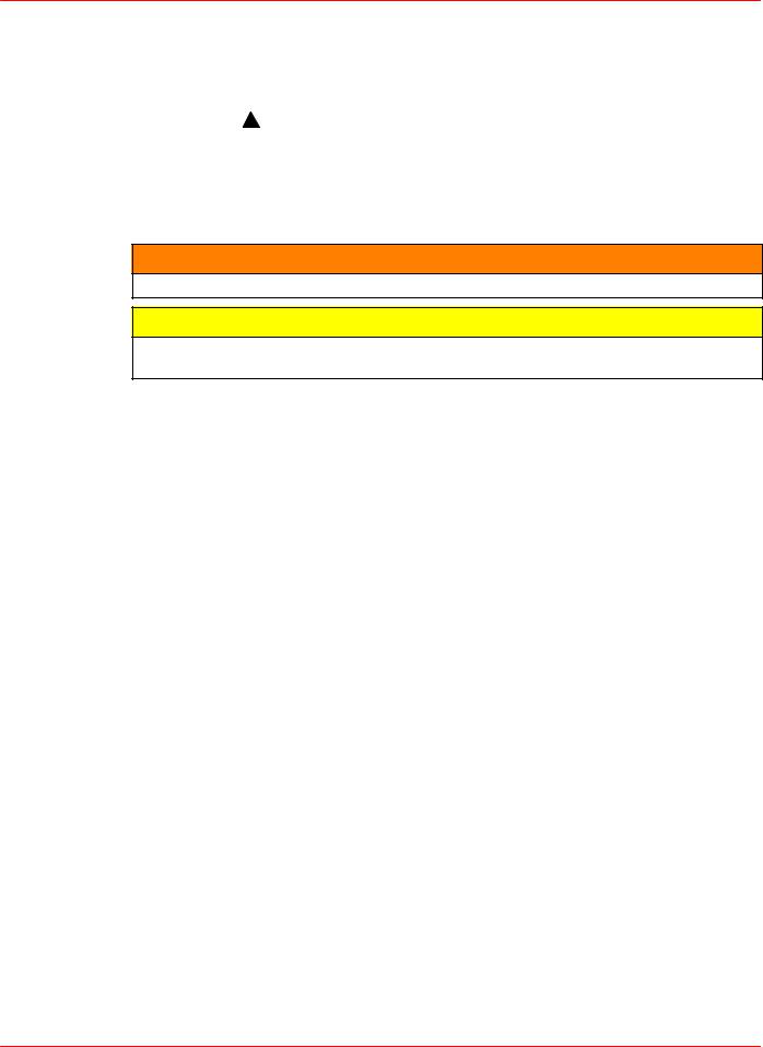
•Avoid an electrical interconnection between the MerCruiser Product, Anodic Blocks, or MerCathode System and the paint by allowing a minimum of 1-1/2 in. (40mm) UNPAINTED area on transom of the boat around these items.
a
b
71176
a- Painted Boat Transom
b- Minimum 1-1/2 in. (40 mm) UNPAINTED Area Around Transom Assembly
NOTE: Drive unit and transom assembly can be painted with a good quality marine paint or an anti-fouling paint that DOES NOT contain copper, tin, or any other material that could conduct electrical current. Do not paint drain holes, anodes, MerCathode system, and items specified by boat manufacturer.
Page 7 of 90
D7.3L D-TRONIC DIESEL ENGINES - BRAVO MODELS
Installation Requirements
Boat Construction
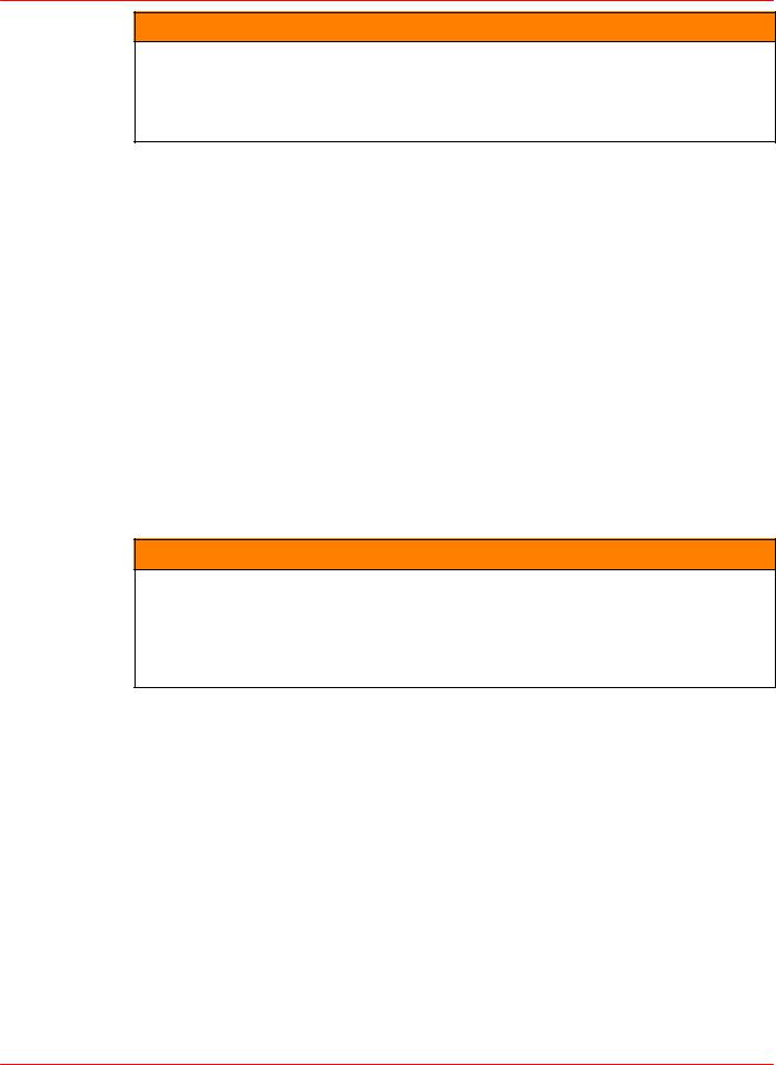
TRANSOM
a
f
c |
e |
e |
b |
22033 |
|
d |
22170 |
|
a- Transom Thickness - 2 in. (51mm) Minimum to 2-1/4 in.(57mm) Maximum
b- Inner Surface of Transom Must Be Parallel Within 1/8 in. (3mm) in Area Covered by Transom Plate (e) and Remain Within Transom Thickness Limits.
c- Outer Surface of Transom Must Be Parallel Within 1/16 in. (2 mm) in Area Covered by Transom Plate (e) and Remain Within Transom Thickness Limits.
d- Remove Keel (if Equipped) 4 ft. (1.2m) Forward to Transom
e- Transom Plate Covers 8 in. (203 mm) to either side of the vertical centerline
f - Transom Angle - 10 Degrees to 16 Degrees
ENGINE BED
Distance between starboard and port engine mount is 22-1/2 in. (572mm). Engine bed must position engine so that a minimum of 1/4 in. (6mm) up and down adjustment still exists on mounts after performing final engine alignment. This is necessary to allow for realigning engine in the future.
NOTE: Although the engine mounts allow some adjustment, it is a good practice to insure that the front and rear mount locations in the vessel are in parallel planes. This may be checked by tying a string from the left front mount location to the right rear mount location and another from right front to left rear. The strings should touch where they cross.
Page 8 of 90

D7.3L D-TRONIC DIESEL ENGINES - BRAVO MODELS
ENGINE COMPARTMENT
 WARNING
Boating standards (NMMA, ABYC, etc.) and Coast Guard regulations must be adhered to when constructing the engine compartment.
Care must be exercised in the design and construction of the engine compartment. Seams must be located so that any rain water, which may leak through the seams, is directed away from the air intake system. Water, that runs onto the air intake, may enter the engine
and cause serious damage to internal engine and/or turbocharger parts.
IMPORTANT: MerCruiser will not honor any warranty claim for engine damage as a result of water entry.
ENGINE COMPARTMENT VENTILATION
General Information
According to Boating standards (NMMA, ABYC, etc.) and Coast Guard regulations the engine compartment ventilation system has multiple tasks. Included are the following:
1.To supply the engine with combustion air.
2.To maintain a low temperature in the engine compartment.
Fresh air should enter the engine compartment as low as possible and the heated air should be discharged from the highest point.
If a separate air shaft (or similar) is used to provide engine compartment ventilation, or additional ventilation, care must be taken to prevent seawater and spray from entering it.
Combustion Air Requirements
Engine compartments with natural draft ventilation must have vent openings of sufficient size and location to accomplish the tasks previously outlined.
Furthermore, in part, and according to, ABYC H-32-89 specification - “Compartment Ventilation (Diesel)” states:
“Ventilating provisions and openings to the machinery space provided for suppling combustion air shall accommodate the air requirements required by the engine manufacturer(s) for each propulsion and auxiliary engine in that space. These openings may also function as means of providing natural ventilation.”
IMPORTANT: The size of ventilation openings must be increased if any auxiliary equipment is located in the engine compartment.
The combustion air requirement (per engine) for the specified engines at Wide Open Throttle are shown in the chart below:
Combustion Air Requirements (Per Engine)
Model |
Engine Air Requirements at |
|
Wide Open Throttle |
||
|
||
|
|
|
D7.3L D-Tronic and D7.3L D-Tronic LD |
1000 ft.3/min. (28.2 m3/min.) |
Page 9 of 90

D7.3L D-TRONIC DIESEL ENGINES - BRAVO MODELS
Multiplying the engine air flow (cfm) by 0.1 will generally determine the combustion air vent size requirement (per engine). Therefore:
|
|
|
|
|
Engine Combustion |
|
= |
Combustion Air Vent Area Per Engine |
|
Air Flow (cfm) X 0.1 |
|
|
(Square Inches) |
|
OR |
|
|
|
|
Engine Combustion Air Flow (m3/min.) X |
= |
Combustion Air Vent Area Per Engine |
||
22.8 |
|
|
|
(Square Centimeters) |
D7.3 D-Tronic Example: |
1000 X 0.1 = 100 Square Inches1 |
|||
OR |
28.2 X 22.8 = 642.9 Sq. Cm.1 |
|
|
|
1 : For engine combustion air only - NOT total engine compartment ventilation requirement.
IMPORTANT: The amount of vent area required, according to Boating standards (NMMA, ABYC, etc.) and Coast Guard regulations, for complete (total) engine compartment ventilation must include the engine vent area, determined by the above formula, plus the engine compartment ventilation requirements.
Compartment Temperature - Specifications
Too high an inlet air temperature lowers the engine performance. Therefore:
Engine compartment temperature shall not exceed outside air temperature by more than 30° F (17° C).
Since many factors influence engine compartment temperature, temperature measurements should always be carried out.
Compartment Temperature - Testing
Test as follows:
1.The boat being tested shall be a standard production boat fitted as it would be for delivery to a dealer.
2.Temperature test meter used shall be of the type that can be read without opening the engine cover.
3.During the test, in Step 4, engine compartments are to remain closed. No outside air is to be forced into the engine compartment during the test and the bilge blower should not be running.
4.Engine Running and Heat Soak Test:
a.Use 1 meter and 1 thermal couple. Position the thermal couple at the engine air inlet (air filter).
b.Start engine to warm it up. After engine is at its normal operating temperature, run engine at WOT rpm for 20 minutes. Record temperature readings at 5 minute intervals.
IMPORTANT: If the temperature at the engine air inlet (air filter) exceeds specifications, the engine compartment will need additional engine combustion air openings, or an increase in engine compartment ventilation area, until the temperature remains within specification.
Page 10 of 90
D7.3L D-TRONIC DIESEL ENGINES - BRAVO MODELS
Exhaust System
IMPORTANT: It is the responsibility of the boat manufacturer or installing dealer to properly locate the engine and install the exhaust system. Improper installation may allow water to enter the exhaust manifolds and combustion chambers and severely damage the engine. Damage caused by water in the engine will not be covered by MerCruiser Warranty, unless this damage is the result of defective part(s).
Determine if an exhaust riser kit or a water lift muffler kit is required, by taking measurements
(a) and (b), with boat at rest in the water and maximum load aboard. Subtract (b) from (a) to find (c). If (c) is less than specified in chart, an exhaust riser kit must be installed.
Model |
(c) = (a) Minus (b) |
|
|
All Models |
(c) Must Be 13 in. (330 mm) or More |
|
b |
a |
d |
|
c |
merCruiser |
|
Typical Engine Without Risers
a- From Waterline to Top of Transom
b- From Highest Point on Exhaust Elbow to Top of Transom
c- Equals (a) minus (b)
d- Waterline at Rest
Page 11 of 90

D7.3L D-TRONIC DIESEL ENGINES - BRAVO MODELS
Some engines may be equipped with a factory installed exhaust riser. Verify that the riser provides the required dimension “c”, or a distance greater than “c”, as indicated.
Model |
(c) = (a) Minus (b) |
|
|
All Models |
(c) Must Be 13 in. (330 mm) or More |
|
b |
a |
c |
d |
merCruiser
76076
Typical Engine With Riser
a- From Waterline to Top of Transom
b- From Highest Point on Exhaust Riser to Top of Transom
c- Equals (a) minus (b)
d- Waterline At Rest
Fuel Delivery System
 WARNING
Boating standards (NMMA, ABYC, etc.) and Coast Guard regulations must be adhered to when installing fuel delivery system.
GENERAL
The main concern of a boat’s fuel system is safety; this must be achieved through a technically sound installation and constant inspection.
The fuel system, from the filler pipe to the fuel pump is the same, in principle, for all boats.
The Fuel Tank is an integrated component of the boat. Refer to the special information on service and maintenance, which you have received from the thank manufacturer.
Only a few points related to function and safety are listed here [Refer to boating standards (NMMA, ABYC, etc.) and Coast Guard regulations for complete guidelines]:
1.All connections should be on the upper side of the tank.
2.The drain plug at the lowest point on the tank serves to permit the removal of water and sediment.
3.The filler pipe outer diameter should be at least 2 in. (50mm).
Page 12 of 90

D7.3L D-TRONIC DIESEL ENGINES - BRAVO MODELS
4.The tank breather pipe must have an inner diameter of at least 1/2 in. (13mm) and must be fitted with a swan neck to prevent water from entering the tank.
It is recommended that the exact route and length of the fuel lines be established at the first installation of the engine to prevent problems later in connecting them to the engine.
All fuel lines must be well secured. The holes where the lines run through the bulkheads should be carefully rounded off, or protected with rubber grommets. This prevents damage to the lines from abrasion.
FUEL CONNECTIONS
The following, but not limited to the following, additional fuel connection related points, applying to all engines unless otherwise stated, must be considered [Refer to boating standards (NMMA, ABYC, etc.) and Coast Guard regulations for complete guidelines]:
1.Fuel pickup should be at least 1 in. (25mm) from the bottom of fuel tank, to prevent picking up impurities.
2.Fuel supply lines must not be smaller than 3/8 in. (11 mm) I.D. tube for V8 model. A fuel return line between engine and fuel tank is required, for all models the return line must not be smaller than 5/16 in. (8 mm).
3.On Multi-Engine Installations: Use a separate tube for the fuel supply line and fuel return line for each engine.
4.Larger diameter (than previously specified) lines, and fittings must be used on installations requiring long lines or numerous fittings.
5.Fuel line(s) should be installed free of stress and firmly secured to prevent vibration and/ or chafing.
6.Sharp bends in fuel lines should be avoided.
7.A flexible fuel line must be used to connect fuel supply line to fuel inlet fitting on engine, to absorb deflection when engine is running. Injection pump fuel return line must also have a flexible rubber hose segment.
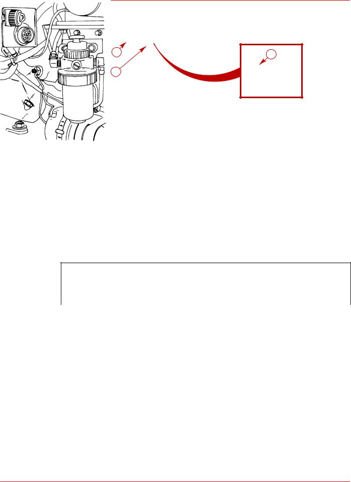
DIESEL FUEL FILTERS AND FUEL ADDITIVES
There is the possibility that contamination of diesel fuel and algae growth in the diesel fuel could cause the blockage of the lift pump resulting in poor performance.
IMPORTANT: The engine is provided with an element type fuel filter, but to help eliminate water and dirt it is recommended to use an additional 10 micron, 60 gal/min. (227 L/min.) flow rated filter that has a water trap.
It is recommended that in MerCruiser Diesel applications, an additional fuel filter equipped with a water trap be installed before the lift pump. MerCruiser recommends a 10 micron, 60 gallon per minute (227 L/min.) rated filter, such as a Racor Model 500 (Quicksilver Part Number 35-850481 with SAE threads, and 35-809867 with Metric threads) or equivalent. This will help to filter out contaminants in diesel fuel.
Select a suitable position in the fuel system between the fuel feed pump and the fuel tank for the additional filter The position selected must be free from vibrations, and allow for easy inspection and replacement.
It is also recommended that a diesel fuel additive be added (to combat algae growth) particularly in warmer climates. Additives reduce the chances of algae growth in the diesel fuel.
Page 13 of 90

D7.3L D-TRONIC DIESEL ENGINES - BRAVO MODELS
Battery
IMPORTANT: Boating industry standards (BIA, ABYC, etc.) federal standards and Coast Guard regulations must be adhered to when installing battery. Be sure battery cable installation meets the pull test requirements and that positive battery terminal is properly insulated in accordance with regulations.
IMPORTANT: It is recommended (required in some states) that battery be installed in an enclosed case. Refer to regulations for your area.
IMPORTANT: Engine electrical system is negative (±) ground.
Select a battery that meets all of the following specifications:
•12-volt marine type.
•Tapered post connectors or side terminal connectors. Do not use a battery with wing nut connectors.
•Battery capacity rating of at least:
Engine |
Minimum Required Cranking |
(Cyl./type) |
Battery Size |
|
|
8 / V, D7.3L D-Tronic and D7.3L D-Tronic LD |
1500 cca, 1920 mca or 300 Ah |
Battery Cables
Select proper size positive (+) and negative (–) battery cables, using chart. Battery should be located as close to engine as possible.
IMPORTANT: Terminals must be soldered to cable ends to ensure good electrical contact. Use electrical grade (resin flux) solder only. Do not use acid flux solder, as it may cause corrosion and a subsequent failure.
Battery Cable Length |
Minimum Cable |
|||
|
Gauge |
|||
|
|
|||
|
|
|
|
|
Up to 3 ft. (0.9m) |
|
2 |
( |
35mm2) |
3 - 3-3/4 ft. (0.9 - 1.1m) |
|
1 |
( |
50mm2) |
3-3/4 - 4-3/4 ft. (1.1 - 1.4m) |
|
0 |
( |
50mm2) |
4-3/4 - 6 ft. (1.4 - 1.8m) |
|
00 |
( |
70mm2) |
6 - 7-1/2 ft. (1.8 - 2.3m) |
|
000 |
( |
95mm2) |
7-1/2 - 9-1/2 ft. (2.3 - 2.9m) |
|
0000 |
(120mm2) |
|
9-1/2 - 12 ft. (2.9 - 3.7m) |
|
00 ( |
70mm2) |
|
12 - 15 ft. (3.7 - 4.6m) |
|
000 ( |
95mm2) |
|
15 - 19 ft. (4.6 - 5.8m) |
|
0000 (120mm2) |
||
:Two cables of specified gauge required for positive and two required for negative.
Page 14 of 90

D7.3L D-TRONIC DIESEL ENGINES - BRAVO MODELS
EDI Electrical System Precautions
NOTE: The following precautions apply to all EDI model Engines.
 CAUTION
Avoid damage to the Electronic Direct Injection (EDI) electrical system and components. Refer to the following precautions when working on or around the EDI electrical harness or when adding other electrical accessories:
•DO NOT tap accessories into engine harness.
•DO NOT puncture wires for testing (Probing).
•DO NOT reverse battery leads.
•DO NOT splice wires into harness.
•DO NOT attempt diagnostics without proper, approved Service Tools.
Instrumentation
GENERAL
We recommend using Quicksilver Instrumentation and Wiring Harnesses. Refer to “Quicksilver Accessories Guide” for selection.
NOTE: If using other than Quicksilver instrumentation and harnesses, refer to manufacturers’ instructions.
The six basic gauges that must be used with the engine are:
•Tachometer
•Oil Pressure
•Water Temperature
•Voltmeter
•Cruise Log (Engine Hour Meter)
•Trim Gauge
When using the instrumentation, instrument harness wire connectors are labeled. It will be necessary to connect them onto the individual Quicksilver instruments, switches and Engine System Monitor panel. The instrumentation harness ends are provided for connection into the appropriate extension harness ends. The wiring harnesses will then be ready to route to the engine.
On dual station applications, oil pressure and water temperature senders (on engine) must be changed.
Additionally, changes are needed in the primary station key switch wiring to allow use of start and stop switches common on dual station panels. Refer to instructions in kit.
When routing any wiring extension harness back to the engine, make sure that the harness does not rub or get pinched. Be sure all extension harness connector collars are secure. Fasten harnesses to boat at least every 18 in. (460 mm) using appropriate fasteners.
Page 15 of 90
D7.3L D-TRONIC DIESEL ENGINES - BRAVO MODELS
c |
b |
|
a
76010
D7.3L D-Tronic Shown - All Similar
a- Engine Harness Connector
b- Extension Harness Connector (From Instruments)
c- Electrical Bracket
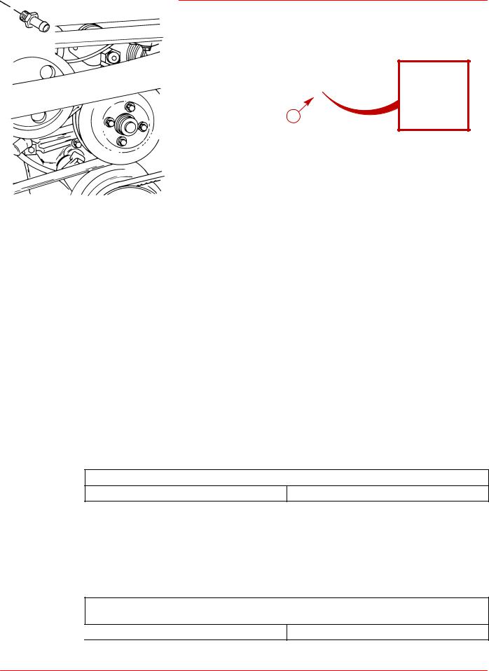
TACHOMETER SPECIAL INFORMATION
IMPORTANT: If using a tachometer from another manufacturer, do not use the magnetic tachometer pickup (or related wiring) mounted on the flywheel housing.
If using the Quicksilver Tachometer provided with the engine package, the appropriate setting of the switch located on the back of the tachometer is given in the following chart.
Tachometer Switch Setting
Model |
Switch Position |
|
(Teeth Count on Flywheel) |
||
|
||
|
|
|
D7.3L D-Tronic and D7.3L D-Tronic LD |
4 (155) |
Power Trim Control
Any of the Quicksilver panel or in-handle type trim controls (that are specified for use with MerCruiser sterndrives) can be used with this Power Trim system. Install trim control in accordance with instructions that accompany it.
Power Trim Pump Location
Select an appropriate mounting location for the trim pump that meets the following requirements:
•Within limits of black and gray hydraulic hoses (coming from gimbal housing assembly).
•Close to the battery so that trim pump battery leads can be connected.
•Allow easy access to trim pump oil fill and vent locations.
•Area where pump will not be exposed to water.
•Trim pump must be mounted so that when steering wheel is turned in either direction (right or left), the power steering booster cylinder does not come in contact with trim pump.
Page 16 of 90

D7.3L D-TRONIC DIESEL ENGINES - BRAVO MODELS
Propeller Selection
GENERAL INFORMATION
IMPORTANT: Installed propeller must allow engine to run at its specified maximum wide-open-throttle revolutions per minute (rpm). Use an accurate service tachometer to verify engine operating rpm.
It is the responsibility of the boat manufacturer and/or the selling dealer to equip the power package with the correct propeller(s). Specified engine wide-open-throttle (WOT) and operating rpm range are listed in the “Operation and Maintenance Manual” attached to the engine.
Select a propeller that will allow the engine power package to operate at or near the top end of the recommended wide-open-throttle operating rpm range with a normal load. High rpm, caused by an excessive trim angle, should not be used in determining correct propeller selection.
If full throttle operation is below the recommended range, the propeller must be changed to prevent loss of performance and possible engine damage. On the other hand, operating an engine above the recommended operating rpm range will cause higher than normal wear and/or damage. Generally, there is a 200 rpm change between propeller pitches.
After initial propeller selection, the following common problems may require that the propeller be changed to a lower pitch:
•Warmer weather and greater humidity cause an rpm loss.
•Operating in a higher elevation causes an rpm loss.
•Operating with increased load (additional passengers, pulling skiers, etc.).
For better acceleration, such as is needed for water skiing, use the next lower pitch propeller. However, do not operate at full throttle when using the lower pitch propeller but not pulling skiers.
Because of the many variables of boat design, only testing will determine the best propeller for a particular application. Available propellers are listed in the “Quicksilver Accessories Guide.”
See “BOAT-IN-THE-WATER TESTS, Maximum rpm Test” in the power package Installation Manual.
RPM REV-LIMITER
IMPORTANT: When selecting a propeller consider this additional information:
The engines listed in the following chart are equipped with a device that limits engine rpm. Be sure that propeller being used does not allow engine to run against limiter, as a significant loss in performance will result.
Engine rpm
MCM Model |
Engine Recommended |
Rpm Limiter Setting |
|
Operating rpm Range |
(Begins At:) |
||
|
|||
|
|
|
|
D7.3L D-Tronic |
3600-3800 |
3850 |
|
|
|
|
|
D7.3L D-Tronic LD |
3400-3600 |
3650 |
Page 17 of 90

D7.3L D-TRONIC DIESEL ENGINES - BRAVO MODELS
Hot Water Heater Installation Recommendation
IMPORTANT: When connecting a cabin heater or hot water heater, certain requirements must be met, including, but not limited to the following:
•Supply hose (from engine to heater) and return hose (from heater to engine) MUST NOT EXCEED 5/8 in. (16 mm) I.D. (inside diameter).
•Make heater connections ONLY at locations indicated in the following information.
•Refer to manufacturers' instructions for complete installation information and procedures.
IMPORTANT: Do not reposition engine temperature switch, it must remain where installed by factory.
 CAUTION
Heater must be mounted lower than the fill cap on the heat exchanger. If the heater is higher than the fill cap on the heat exchanger and some coolant is lost from system, an air pocket may form in the closed cooling system. This can cause the engine to overheat.
A Hot Water Heater Adaptor Kit is available from Quicksilver. This kit contains installation instructions. Locations for fittings are shown following.
PART NUMBER |
DESCRIPTION |
854570A1 Hot Water Heater Adaptor Kit
SUPPLY HOSE CONNECTION
a
71898
76024
a - Location for Water Heater Supply Hose (Bayonet Fitting Replaces Plug)
Page 18 of 90
D7.3L D-TRONIC DIESEL ENGINES - BRAVO MODELS
RETURN HOSE CONNECTION
a
76023
a- Location on Water Circulation Pump for Hot Water Return (Bayonet Fitting Replaces Plug)
Seawater Connections
D7.3L D-Tronic and D7.3L D-Tronic LD models must be equipped with a through hull or through transom water supply to ensure sufficient water flow to the engine. The transom assembly needs to be modified with the water passage block-off plate kit (P/N 818304A1) provided. It is necessary to cut the water hose that is located between the bell housing and the gimbal housing. This allows water to continue through the drive for cooling. Refer to “Drive Unit Seawater Routing.” outlined later. Read and observe the following to select the proper seawater pickup hose, seacock size and seawater strainer.
Seawater Connections - General Information
SEAWATER PICKUP HOSE
Seawater inlet hose connections must be made with wire reinforced hose of adequate wall thickness to prevent it from collapsing from pump suction. Be sure to secure hose connections with hose clamps. Secure hose to prevent contact with any moving parts of the engine.
Seawater Pickup Hose Inner Diameter
All Models |
1-1/2 in. (38mm) |
SEACOCK SIZE
Seacock used must have an internal cross-sectional area equal to or greater than seawater inlet hose to prevent restricting water flow. Install valve in an area where it will be easily accessible and supported adequately to prevent hose fatigue. A brass ball or gate valve is required.
Seacock Size
(Internal Cross-Sectional Area Equal to or Greater Than Size Shown)
All Models |
1-1/2 in. (38mm) |
Page 19 of 90

D7.3L D-TRONIC DIESEL ENGINES - BRAVO MODELS
SEAWATER STRAINER
Strainer used must be of sufficient size to ensure that an adequate supply of water will be maintained for cooling the engine.
Seawater Strainer Minimum Flow Rate 1
All Models |
40 (150) |
1 Amount listed is in gallons per minute and (liters per minute).
Install seawater strainer in an area where it will be easily accessible for inspection and cleaning. Strainer should be installed in water inlet hose after the seacock (water inlet valve) to allow operator to shut off water when cleaning strainer.
Throttle/Shift Remote Control and Cables
To ensure proper shift and throttle operation, we recommend the use of a Quicksilver remote control and cables. Refer to “Quicksilver Accessories Guide” for selection. However, if a control other than Quicksilver is to be used, control must provide the following:
Shift Cable Travel |
Shift Cable Load |
(At shift plate end.) |
(Applied to the cable end guide.) |
|
|
2-7/8 in. (73mm) to 3-1/8 in. (80mm) |
15-20 lb. (6.8-9 kg) |
Page 20 of 90
D7.3L D-TRONIC DIESEL ENGINES - BRAVO MODELS
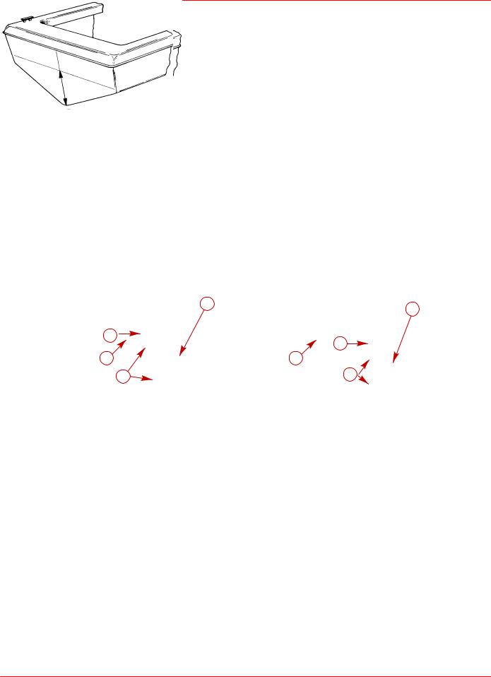
Steering Helm and Cable
Transom assembly is shipped with the steering cable guide tube preset for cables with end dimensions that comply with ABYC standards as outlined in the NMMA certification handbook. The steering cable coupler nut must also have a means of locking it to the guide tube as specified in ABYC requirements.
 WARNING
Failure to use a steering cable locking device could cause loss of steering, which could cause damage to the boat and/or injury.
All current production Quicksilver Ride Guide steering cables have a self-locking coupler nut and do not require an external locking device. (Other cable manufacturers also make cables with self-locking coupler nut.)
a
22060
a- Quicksilver Ride Guide Steering Cable Self-Locking Coupler Nut (Identified by Groove)
If using a steering cable that does not have a self-locking coupler nut, an external locking device must be used.
|
c |
b |
e |
|
a
 f d
f d
a- Steering Cable
b- Grease Fitting
c- Cotter Pin
d- Locking Sleeve (If Required - Must Be Ordered Separately)
e- Cable Coupler Nut
f - Cable Guide Tube
Page 21 of 90

D7.3L D-TRONIC DIESEL ENGINES - BRAVO MODELS
 CAUTION
POWER STEERING EQUIPPED UNITS ONLY: If steering cable with improper dimensions is installed, severe damage to transom assembly and/or steering system may result.
1.Steering cable must be the correct length, particularly when installed in larger boats.
2.Avoid sharp bends, kinks or loops in cable.
3.Fully extended steering cable end dimension must be as shown.
STEERING CABLE SPECIFICATIONS
a
|
c |
|
b |
|
d |
e |
|
g |
f |
|
|
|
C |
|
|
|
L |
k |
j |
h |
l |
|
i |
21435
a- Coupler Nut - 7/8 - 14 UNF - 28 Thread
b- 11-3/4 in. (298 mm) Min.
c- Interface Point
d- 1/2 in. (12.700 mm) Max.
e- .420 in. (10.668 mm) Min. Flat
f - .102 in. (0.508 mm) Min. Radius
g- 5/8 in. (15.875 mm) Max. Diameter End Fitting
h- 3/8 in. (9.525 mm)
i- .385 in. (9.779 mm) Diameter Thru Hole, Chamfered Each Side
j- 1-3/8 in. (34.925 mm) Max
k - 5/8 in. (15.875 mm) Diameter Tube
l- Mid-Travel Position - 16-7/8 in. (428.6 mm) Total Travel To Be 8 in. (203.2 mm) Min. to 9 in. (228.6 mm) Max Travel Each Side of Mid-Travel Position - 4 in. (101.6 mm) Min., 4-1/2 in. (114.3 mm) Max.
a |
b |
c
21436
a- Steering Cable Mounting Flange
b- Center of Hole in Steering Cable End
c- 21-3/8 in. (543 mm) Max.
Page 22 of 90

D7.3L D-TRONIC DIESEL ENGINES - BRAVO MODELS
Transom Cutout
NOTICE to INSTALLER
Before Starting Installation Read “General Information” and “Installation Requirements” Sections Completely.
IMPORTANT: The following instructions will provide a sterndrive unit mounting location that is suitable for most boats. Best mounting location for a particular boat, however, can be determined only by testing.
Bravo Models use items 1 - 4.
1.Below 25 m.p.h. (40 km/h): Subtract 1/2 in. (13mm) from “X” Dimension Shown.
2.Heavy Duty Applications: Subtract 1 in. (25mm) from “X” Dimension shown.
3.Above 25 m.p.h. (40 km/h): Use “X” Dimension shown.
4.Above 50 m.p.h. (80 km/h): The “X” Dimension can be increased to improve performance in some applications, but pulling power (for skiing) will decrease. During testing, “X” Dimension should be increased 1/2 in. (13mm) at a time until desired performance is achieved but in no case should it ever be increased by more than:
Bravo One/Two: 3 in. (76 mm) maximum.
Bravo Three: 1 in. (25 mm) maximum.
In ALL applications where cooling water is supplied through the sterndrive unit to the engine, extreme care should be taken when raising drive unit to ensure that the water supply does not become aerated. Use a clear, water inlet hose to check incoming water for aeration. Monitor engine temperature gauge to ensure engine does not overheat.
In applications where cooling water is supplied to the engine by a fitting through the hull or transom, the sterndrive height will not cause cooling water aeration.
IMPORTANT: Damage to MerCruiser products caused by too high of an installed height will not be covered by MerCruiser warranty.
Page 23 of 90
D7.3L D-TRONIC DIESEL ENGINES - BRAVO MODELS
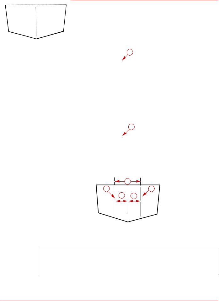
Finding Crankshaft Vertical Centerline
SINGLE ENGINE
Locate and mark vertical centerline on transom.
a
71620
a - Vertical Centerline
DUAL ENGINE
1. Locate and mark boat vertical centerline (a) on transom.
a
71620
a- Vertical Centerline
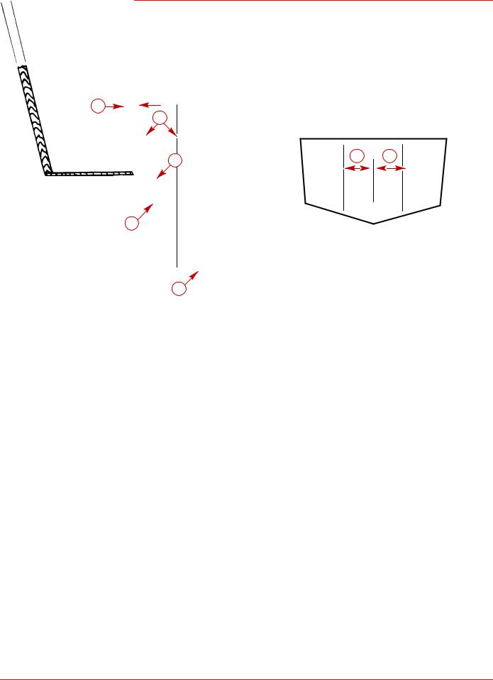
2.Locate and mark crankshaft vertical centerlines (a) on transom.
|
b |
a |
a |
c |
c |
22033
a- Draw Crankshaft Vertical Centerline through Desired Mounting Locations
b- Minimum Distance between Crankshaft Vertical Centerlines
c- Crankshaft Vertical Centerlines Must Be an Equal Distance from Boat Vertical Centerline
Minimum Distance Between Crankshaft
Vertical Centerlines (Dual Side-By-Side) Chart
Model |
Measurement [ in. (mm) ] |
|
|
D7.3L D-Tronic and D7.3L D-Tronic LD |
36-1/2 (927) |
Page 24 of 90
D7.3L D-TRONIC DIESEL ENGINES - BRAVO MODELS
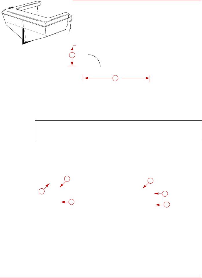
Finding Crankshaft Horizontal Centerline (ªXº Dimension)
“X” Dimension can be measured by the “90° Tool Method” or by the “Tape Measure Method.”
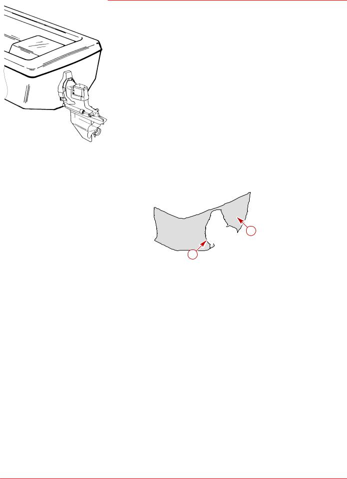
90° TOOL METHOD
1. Construct 90° tool.
a |
° |
|
90 |
b
71621
a- Dimension from Chart Below
b- Measurement: 4 ft. (1.2 m)
To Lower Drive Unit - Subtract from dimension “a”.
To Raise Drive Unit - Add to dimension “a”.
90° TOOL VERTICAL DIMENSION CHART
Sterndrive Unit |
Location |
|
|
Bravo One/Two/Three |
13-9/16 in. (345mm) |
IMPORTANT: This dimension should only be raised or lowered after proper testing.
2. Determine “X” Dimension location of crankshaft centerline(s).
b |
|
c |
|
c |
|
b |
|
|
|
|
|
a |
71622 |
a |
71623 |
|
|
||
|
|
|
|
Single Engine |
|
Dual Engine |
|
a- Place 90° Tool Along Boat Bottom at Vertical Centerline
b- Point at Which Top of Tool Contacts Transom on Vertical Centerline is Crankshaft Horizontal Centerline.
c- Draw a Line Perpendicular to Vertical Centerline at Crankshaft Horizontal Centerline.
Page 25 of 90
D7.3L D-TRONIC DIESEL ENGINES - BRAVO MODELS
TAPE MEASURE METHOD
Transom angle must be known, then measure “X” Dimension with tape measure. 1. Determine “X” Dimension from the following chart.
Tape Measure Method Chart
Model |
Bravo One / Two / Three |
|
|
|
|
Transom Angle |
This dimension should only be raised or lowered after proper |
|
testing. |
||
|
||
|
|
|
16° |
14-5/16 in. (364 mm) |
|
|
|
|
15° |
14-1/4 in. (362 mm) |
|
|
|
|
14° |
14-3/16 in. (360 mm) |
|
|
|
|
13° |
14-1/8 in. (359 mm) |
|
|
|
|
12° |
14-1/16 in. (357 mm) |
|
|
|
|
11° |
14 in. (356 mm) |
|
|
|
|
10° |
13-15/16 (354 mm) |
|
|
|
2. Measure and layout horizontal centerlines as shown.
|
b |
|
b |
|
|
|
|
c |
|
c |
|
|
|
|
|
d |
|
d |
|
a |
|
a |
71623 |
|
|
|
|
|
|
71622 |
|
Single Engine |
|
Dual Engine |
|
a- “X” Dimension (from Chart) that Corresponds to Transom Angle - Measure Up from Boat Bottom with Tape Measure
b- Crankshaft Horizontal Centerline
c- Vertical Centerline
d- Draw a Line Perpendicular to Vertical Centerline at Crankshaft Horizontal Centerline
Page 26 of 90
D7.3L D-TRONIC DIESEL ENGINES - BRAVO MODELS
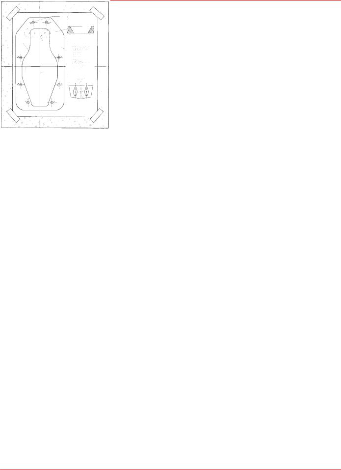
Cutting Transom
Transom cutout can be made by either using the Template [shipped with transom assembly] or the Transom Drilling Fixture Kit (purchased separately).
Follow instructions indicated on template or provided with drilling fixture.
IMPORTANT: Read and observe the following information:
•Be certain that centerlines on either the template or transom drilling fixture align with lines previously marked on transom.
•Be sure to drill 1/4 in. pilot holes (for hole saw guide) at a 60° angle and to cut on the line when making transom cutout. If cutout is made incorrectly, drive unit steering lever may contact transom, thus limiting steering travel.
•Seal inside edge of transom cutout opening with a suitable sealant to prevent water absorption and deterioration of transom.
50017
Transom Cutout Template
22056
Transom Drilling Fixture Kit
Page 27 of 90
 Loading...