


Mercedes-Benz OM906LA Mercedes-Benz OM926LA
Repair manual
Service & Parts

1044-004

Table of contents
Introduction
General Information.................................................................................................................................
General repair instructions.....................................................................................................................
Torque settings........................................................................................................................................
CCN explanation
CCN (CLAAS Component Number)........................................................................................................
CCN (CLAAS Component Number)
Safety
General Information.................................................................................................................................
01 Engine
0102 Complete component.....................................................................................................................
0105 Engine suspension.........................................................................................................................
0110 Engine housing...............................................................................................................................
0115 Engine unit......................................................................................................................................
0120 Cylinder head / Valves / Idler gear................................................................................................
0125 Injection - / Fuel system.................................................................................................................
0130 Lubricating oil system....................................................................................................................
0135 Cooling system...............................................................................................................................
0140 Exhaust system..............................................................................................................................
0145 Air intake.........................................................................................................................................
0150 Engine attachment parts................................................................................................................
0155 Engine control.................................................................................................................................
0165 Exhaust gas treatment...................................................................................................................
1044-004
4
8
20
32
36
48
59
61
81
117
152
176
196
212
231
234
255
257
Index....................................................................................................................................
284
00 0296 433 2 - RHB Dieselmotor OM906/926LA - 10/2014 3

Introduction
General Information
Introduction
1044-004
General Information
Validity of manual
This manual applies to the Mercedes-Benz diesel
engines below:
Engine Type design Engine no.
OM 906 LA 906.991 906.991-00-xxxxxx
OM 926 LA 926.929 926.929-00-xxxxxx
OM 926 LA 926.959 926.959-00-xxxxxx
OM 926 LA 926.970 926.970-xx-xxxxxx
Handling the manual
This repair manual should help you to maintain
ongoing operational capacity. The high value of the
harvesting machine is ensured through careful
maintenance and technical monitoring by customer
service.
This repair manual is a compilation of our service
technicians' and shop-floor experience.
162113-001
123139-005
The picture sequence demonstrates the steps in a
repair procedure. The text provides you with the
information required for making adjustments, using
special tools and further similar information.
Essential repairs are listed in such a way that even
individual and small repairs can be easily found and
followed.
Supplements are added to reflect the ongoing
technical development of the machines and the
manual is thereby continuously being updated as a
reference book.
As a precaution, always compare the setting values
and fill quantities with the most recent operator's
manual and the technical systems documents for the
respective machine.
Texts and figures
Pictures and graphics apply to all models covered by
this manual. Differences are highlighted by captions
below the figures.
In general, texts are short and apply to all models
covered by this manual. Differences are highlighted by
intermediate headings.
Different text categories can be easily identified by the
formatting. The following different formattings are
distinguished:
4 00 0296 433 2 - RHB Dieselmotor OM906/926LA - 10/2014

Formatting Meaning Description
Description Descriptive text Further information on the subject.
Introduction
General Information
1044-004
Procedure
–
instructions
Process Operations which must be carried out one after the
other.
Result Result Result of the processes carried out.
References can be easily identified by corresponding
symbols. The following symbols are distinguished:
Symbol
Meaning Description
See index
The symbol indicates that further information on
this subject is available in other sections of this
manual.
See the index of the
Operator's Manual in
question
The symbol indicates that further information on
this subject is available in the Operator's Manual of
the machine or of the implement in question.
Document structure based on the assembly structure
The chapters of the present manual are subdivided
into assemblies as far as contents permit. The
structure of these assemblies is the same in all
chapters.
Different product groups have different assembly
structures. CLAAS makes every effort to keep this
assembly structures identical in any document.
Search and find
Due to the constantly recurring assembly structure,
the subject in question can be quickly found using the
table of contents or the header of this manual.
In addition, the index provided in this manual is a
useful tool for locating a subject. The index can be
found on the last pages of this manual.
Directions
Front, rear, right and left refer to the direction of
forward travel. If necessary, a direction arrow is used
for indicating the direction of travel in figures.
00 0296 433 2 - RHB Dieselmotor OM906/926LA - 10/2014 5

Introduction
General Information
Abbreviations
Abbreviation Description
bar bar (unit for pressure)
approx. approximately
cm Centimetre
DIN German Standardization Institute
EC European Community
EN European Standard
GPS Satellite navigation system
h Hours
Ident no. Identification number of machine
ISO International Standardization Organisation
kg Kilogram
1044-004
kPa Kilopascal
km Kilometre
km/h Kilometres per hour
m Metre
mm Millimetre
Nm Newtonmetre
psi pound per square inch
StVZO German Regulations Authorizing the Use of Vehicles for Road Traffic
e.g. for instance
% percent
°C degrees Celsius (unit for temperature)
6 00 0296 433 2 - RHB Dieselmotor OM906/926LA - 10/2014

General Information
Technical terms
Technical term Description
recycle Re-use of used, defective or no longer required products
Season Recurring periods of a year
Ignition TDC Ignition top dead centre (diesel engine piston position)
Overlap TDC Valve overlap top dead centre (diesel engine piston position)
BDC Bottom dead centre (diesel engine piston position)
Your CLAAS Service Department
Introduction
1044-004
00 0296 433 2 - RHB Dieselmotor OM906/926LA - 10/2014 7

Introduction
General repair instructions
General repair instructions
Technical specifications
Information on proper repairs
1044-004
123153-002
Technical specifications, dimensions and weights are
non-binding. Technical specifications are subject to
modification in the course of technical development,
and all errors and omissions are excepted.
123192-003
Mark rotating machine components before
►
removing or dismounting them in order to ensure
well-balanced component seating on the correct
side after refitting.
The slots of expansion pins must always point to
►
the loaded side.
When they are installed with a 90° twist, they
come loose, fall out or shear off.
Replace cotter pins, locking wires, sheet retention
►
devices, lock washers and spring washers in the
repair process.
Align sprockets and V-belt pulleys with one
►
another.
Observe the information in the hydraulic system
►
chapter when working on the hydraulic system.
Do not mix different oil grades.
►
Self-locking bolts
Liquid locking compound
151599-001
Self-locking bolts must not come in contact with
sealing compound.
Tighten self-locking bolt speedily up to the
►
specified torque.
► The full hardening time can be reduced by
heating-up, e.g. to 15 minutes at + 70 °C.
► The full load capacity is achieved after
24 hours at + 20 °C.
When unscrewing self-locking bolts, unscrew
►
them quickly.
Use liquid locking compound (glue) only at the
►
spots described in the Repair Manual.
The surfaces to be joined must be absolutely
►
clean and free of grease.
► A suitable cleaner and an activator possibly
delivered along with the glue can be used for
cleaning.
No cleaner residues may remain on the surfaces
►
to be joined.
This applies in particular to tapped holes with a
bottom.
► Let the surfaces dry well before applying the
1
glue.
123164-004
120820-003
8 00 0296 433 2 - RHB Dieselmotor OM906/926LA - 10/2014
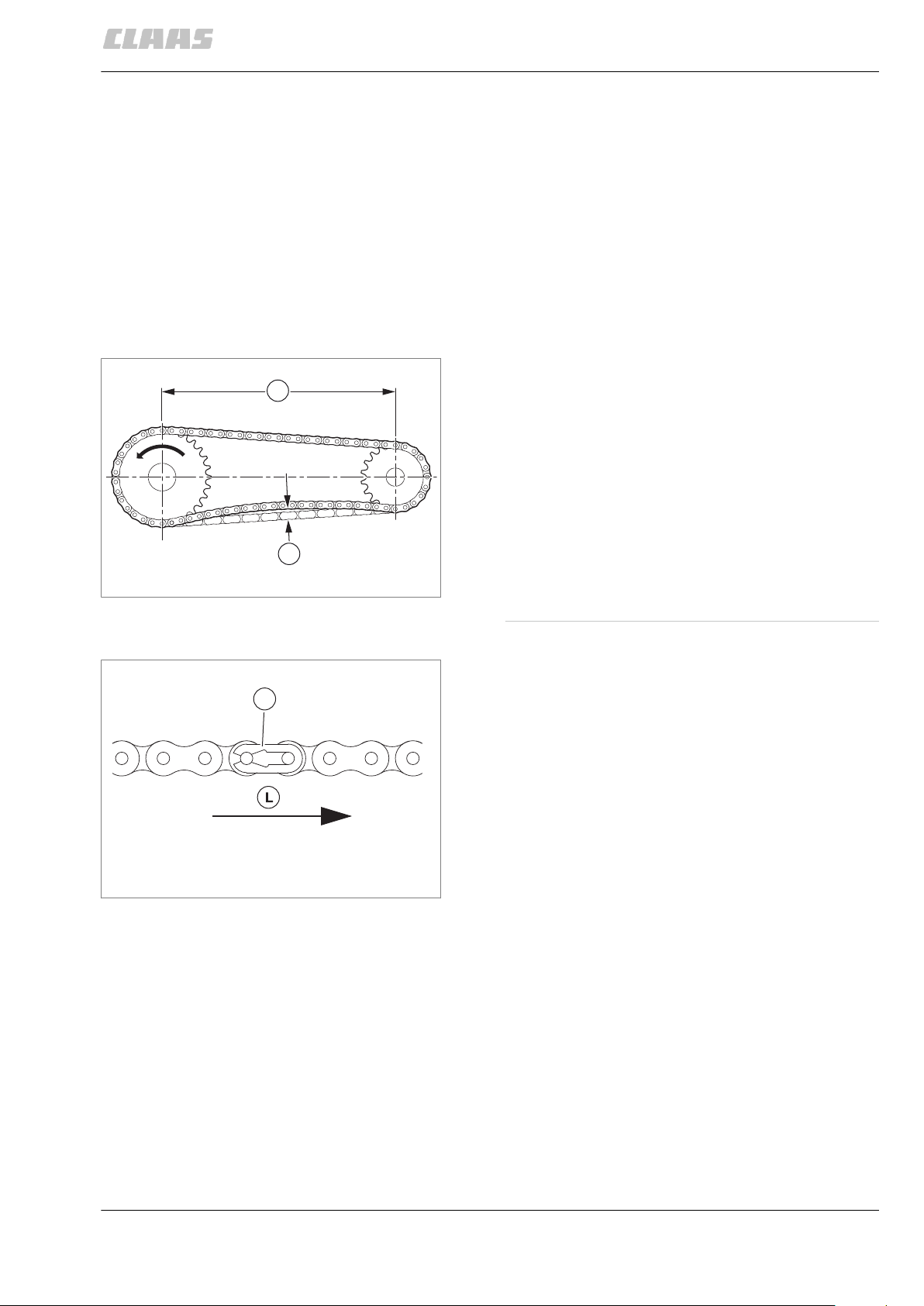
Steel roller chains
A
x
1
Introduction
General repair instructions
Apply the glue only in the areas shown in the
►
figure if possible.
When applying the glue at an unfavourable spot
or when applying too much glue, the joint may
tear off when loosening.
Observe the glue producer's instructions for use
►
and application!
A joint secured by liquid locking compound can be
loosened by heating up to approx. 200 °C.
120771-004
Tensioning
Checking the tension of steel roller chains:
Apply a small load to the tight span.
►
Push down the slack span in the middle between
►
the sprockets with your thumb.
You should be able to push down the slack span
around 2 % of the spacing between the axles.
1044-004
13827-006
123668-001
Example:
Axle spacing (A) = 500 mm
Pushing distance (x) of slack span = approx. 10 mm
2
Chain connector
The closed side of chain connector (1) must point
►
in running direction (L)!
3
00 0296 433 2 - RHB Dieselmotor OM906/926LA - 10/2014 9
1
2
4
3
2
1
4
5
4
3
2
1
Introduction
General repair instructions
Taper ring fasteners
Dismounting
Slacken off tapered ring (1) with a blow.
►
► Use an auxiliary tool (2) if required.
1044-004
120801-005
154769-001
154486-001
4
Installation
NOTICE! Sticking together at the taper ring fasteners.
The joint cannot be loosened or comes off only with
difficulty.
► Do not install parts with tough grease.
Clean shaft (1), hub (2), parallel key (3) and
►
tapered rings (4) thoroughly and apply some
CLAAS AGRIGREASE LC 00 / 000.
Tighten to the specified torque.
►
► In case of several taper ring fasteners fitted
behind one another, tighten those
5
separately.
► Use an auxiliary tool (5) if required.
13975-003
154768-001
10 00 0296 433 2 - RHB Dieselmotor OM906/926LA - 10/2014
6
Gib head key joints
2
1
2
1
2
1
General repair instructions
Dismounting
Slacken off gib head key (1) with a blow if
►
possible.
► Use an auxiliary tool (2) if required.
Introduction
1044-004
123163-004
154811-001
154813-001
7
Drive out the gib head key (2) with a key
►
drawer (1).
► Ensure that the key drawer is used as shown
in the figure.
8
154812-001
Installation
The gib head key (1) comes in raw condition as a
spare part and must be machined to suit the
application by milling or grinding.
9
00 0296 433 2 - RHB Dieselmotor OM906/926LA - 10/2014 11
2
1
3
1
2
4
3
2
1
Introduction
General repair instructions
Lock collar bearing
154492-001
Grind the gib head key (1) to suit the application
►
at surface (2).
► Surface (3) must not be machined.
Clean shaft, hub and keyway to be free of grease,
►
paint and rust prior to assembly.
NOTICE! Excessive force employed when installing
the gib head key. Damage to the gib head key joint.
The gib head key cannot be removed any more.
► Drive in the gib head key carefully with a suitable
and not too heavy hammer.
Ensure that the gib head key is driven in only so
►
10
far that it can still be removed without problems,
using a key extractor.
Dismounting
Slacken off set screw (1).
►
Drive off eccentric ring (2) against the shaft's
►
sense of rotation.
Remove bearing.
►
1044-004
85675-003
123167-002
154814-001
Installation
11
Tighten lock collar bearing (1) on the shaft by
►
twisting eccentric ring (2) over the inner bearing
race (3).
► Arrest the eccentric ring with moderate force
in the sense of rotation of the shaft.
► To make dismounting easier, the inner race
and the shaft can be coated with
CLAAS AGRIGREASE LC 00 / 000.
Tighten set screw (4).
►
12
154500-001
12 00 0296 433 2 - RHB Dieselmotor OM906/926LA - 10/2014

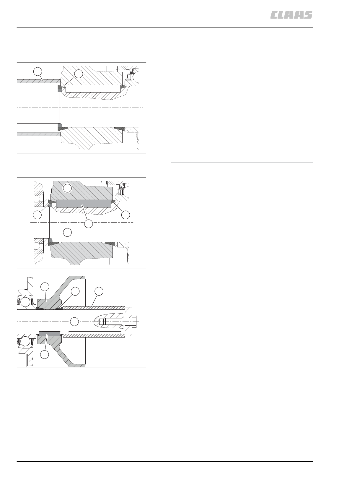
Adapter sleeve bearings
3
2
1
3
2
1
3
1
2
General repair instructions
Dismounting
Loosen the tab of sleeve nut (3).
►
Slacken off sleeve nut by some turns only.
►
► Ensure that the thread is still completely
engaged.
Slacken off expansion pin (2) with a firm blow.
►
Pull off adapter sleeve bearing (1) completely.
►
Introduction
1044-004
120831-003
Chuck bushing
154510-001
154510-001
13
Installation
►
►
►
►
►
►
14
Dismounting
►
►
►
Clean expansion pin (2) and shaft and check easy
movement of the sleeve nut (3).
Install adapter sleeve bearing (1) according to the
conical inside ring (2).
Tighten the sleeve nut with the suitable special
tool and to the prescribed torque.
Continue tightening the sleeve nut to the specified
degrees.
Tighten sleeve nut until the nearest tab can be
applied.
Secure sleeve nut with the tab.
144598-002
Unscrew bolts (1).
Screw in bolts (1), or longer bolts if required at (2).
► Screw in bolts until the chuck bushing (3)
comes loose.
► Apply a little oil to bushing if necessary.
Remove the chuck bushing if required.
Version 1 154820-002
00 0296 433 2 - RHB Dieselmotor OM906/926LA - 10/2014 13
15
3
1
1
1
2
3
4
max. 180°
1
2
Introduction
General repair instructions
1044-004
Version 2 154836-002
16
Installation
Clean chuck bushing (1) and shaft thoroughly.
►
Insert chuck bushing.
►
► Ensure that slots (3) and (4) are mounted
with the maximum possible angle offset.
Tighten bolts (2) evenly crosswise in three steps.
►
► Observe the specified torques of the
respective steps.
17
Version 1
185680-001
18
Version 2 154844-002
14 00 0296 433 2 - RHB Dieselmotor OM906/926LA - 10/2014
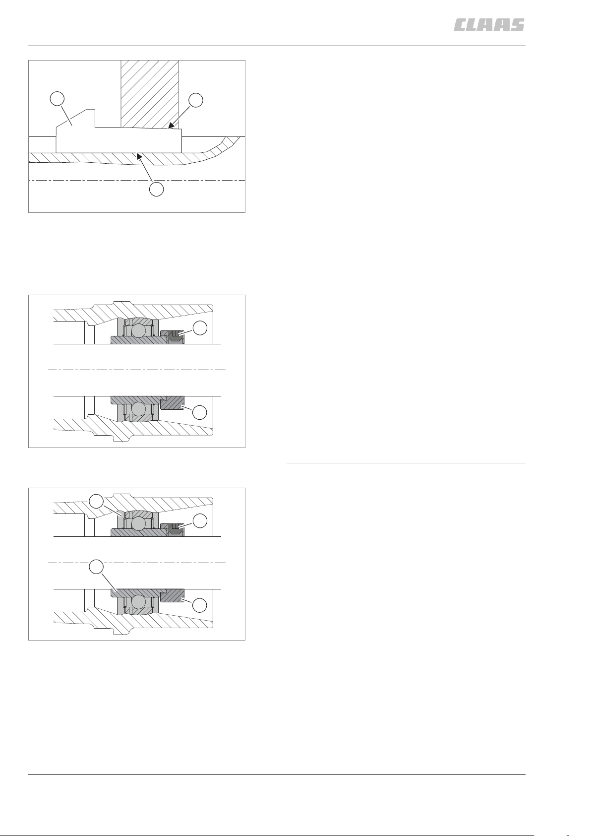
Circlips
1
1
Introduction
General repair instructions
1044-004
144716-004
144718-002
NOTICE
Overspreading the circlip.
Plastic material deformation.
No safe fixing of component.
► Spread circlip only as far as needed for
installation and dismounting.
► Do not use any circlip already overspread before.
Insert circlips as shown in the figures.
►
► Ensure that chamfer (1) does not make
contact with the component to be secured.
► If required, make circlip engage with a slight
blow.
Circlip DIN 471 155144-001
Circlip DIN 472 155145-001
19
20
00 0296 433 2 - RHB Dieselmotor OM906/926LA - 10/2014 15
3
2
1
4
3
2
1
Introduction
General repair instructions
Ferrule fittings
Ferrule without seal 154515-001
Ferrule with seal 154516-001
Screwing in
►
►
►
►
►
21
►
►
►
22
►
►
1044-004
120840-004
Cut off the corresponding tube at right angles.
► Do not use a pipe cutter.
In case of pipe bends, the straight pipe end up to
where the bending radius starts must be at least
twice the height of the union nut.
Slightly deburr the pipe end on the inside and
outside.
► Do not chamfer the pipe end.
Clean the pipe end.
Push the union nut (1) and the ferrule (2) on the
pipe.
Push the pipe against the stop in the connector
(3) and tighten the union nut until the ferrule
seizes the pipe.
This pressure point can be felt because increased
power is needed from here.
The pipe must be fixed securely during assembly
and must not rotate.
Tighten the union nut by half a rotation beyond
the first pressure point.
Check the incision at the cutting edge.
A visible collar must fill the space ahead of the
ferrule face end.
The ferrule may rotate, but axial displacement
must not be possible.
Insert the pre-assembled pipe into the well-oiled
threaded joint.
Screw on the union nut until the power needed to
do this clearly increases.
After that, continue to screw the union nut on for
half a turn beyond that point.
► Observe the tightening torques. Page
23
Non-tight ferrule connection
If a connection leaks, loosen the union nut until
►
some oil escapes.
Then tighten according to instructions.
►
Replace the seal (4) if required.
►
16 00 0296 433 2 - RHB Dieselmotor OM906/926LA - 10/2014

Sealing cone fittings
32
1
XXX / 250 bar / 13/07
XXX / 250 bar
/ 13
/07
1
1
XXX / 250 bar / 13/07
32
Introduction
General repair instructions
Apply seal (1) on the sealing cone (2).
►
Tighten the union nut (3) a third of a turn beyond
►
the point where resistance is felt.
► Observe the tightening torques! Page
24
1044-004
123189-002
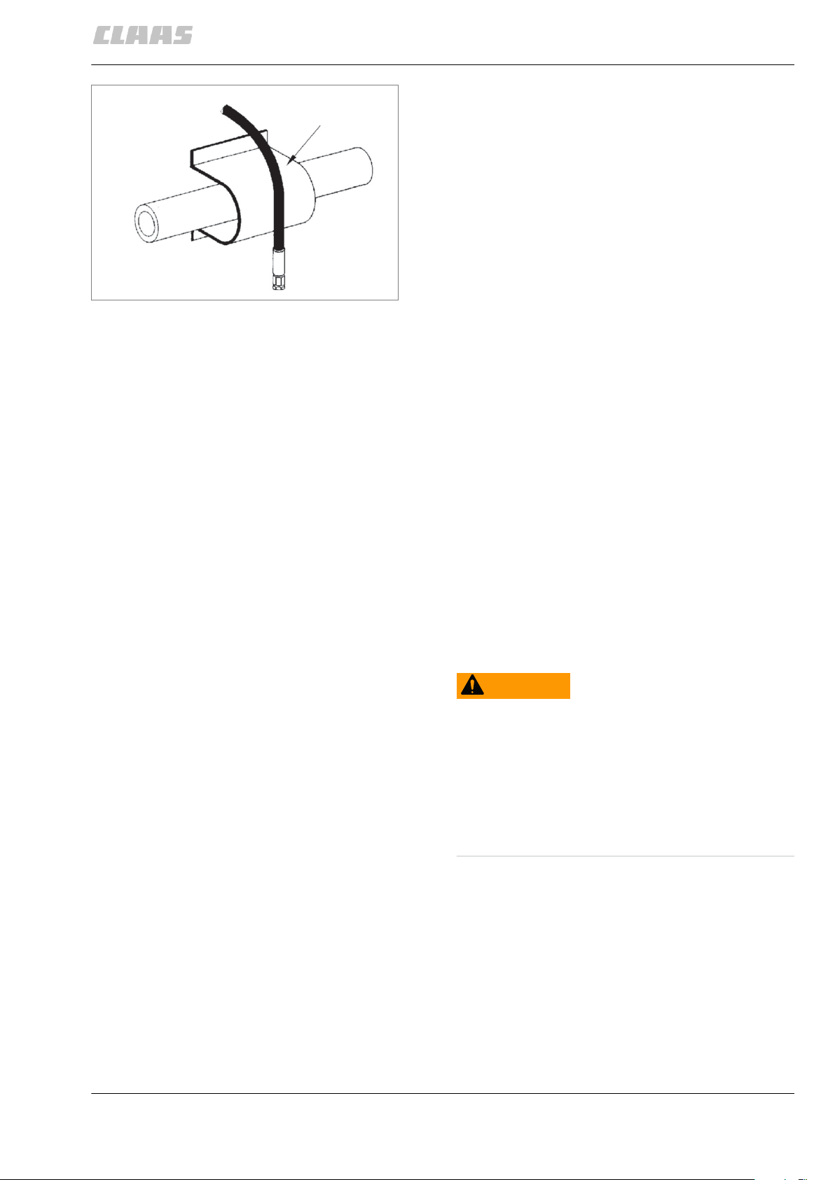
Hydraulic hoses
154527-001
23
NOTICE
Failure of hydraulic hose lines due to ageing.
Uncontrolled lowering of machine parts.
► Replace hydraulic hose lines 6 years after
manufacture at the latest.
To facilitate identifying of hydraulic hoses, each hose
has the CLAAS part number printed on it.
Check hydraulic hoses before initial
►
commissioning and thereafter at least once a
year.
In the case of damage and ageing, replace
►
hydraulic hoses.
The date of manufacture can be seen on the hose
fittings (1).
120856-007
124582-003
(2) = year (e.g. 12 = 2012)
(3) = month (e.g. 07 = July)
24
40202-004
00 0296 433 2 - RHB Dieselmotor OM906/926LA - 10/2014 17
Introduction
General repair instructions
5727-002
Hose placement
NOTICE! Hoses laid in a straight line get shorter as
the hydraulic pressure is built up. Valves may be torn
off.
► Always install hoses with a slight slack.
Install hoses so that no tension or compression
►
loads will occur in any operating conditions.
► Check: If you shake the hose line in the
middle between two brackets/connectors
(e.g. clamps), the overall play of the hose
line should be at least 1 cm.
25
Do not install hose with a twist.
►
► Particularly if there is movement at the hose
line.
1044-004
13989-003
5728-002
5729-002
5726-002
26
27
28
Avoid external mechanical impacts on hoses.
►
► Avoid chafing the hoses against each other
or against components through proper
placement and fastening.
► Keep an adequate distance from
components.
► Keep sharp-edged components covered at
all times.
When high outside temperatures are involved,
►
install hose lines at a sufficient distance from
components radiating heat.
► If necessary, protect hose by a protective
guard.
18 00 0296 433 2 - RHB Dieselmotor OM906/926LA - 10/2014
Introduction
General repair instructions
1044-004
Treatment of sealing faces
Spare parts
5730-002
29
157962-002
Close all oil, coolant and fuel bores thoroughly prior to
treating the sealing faces.
Ensure that when treating sealing faces of
components containing oil, coolant and fuel, no
abrasives are used. Loose particles cause pollution
and damage.
Ensure that no seal residues, rust, lime and
combustion residues end up in open components
(gearbox halves).
Remove sealing residues, rust, lime and combustion
residues only using scraping tools or cleaning agents.
123155-004
11210-003
WARNING
Use of unauthorised spare parts.
Death or serious injury.
► Spare parts must at least comply with the
technical standards required by the manufacturer
of the implement!
► We recommend using genuine CLAAS spare
parts.
Please quote the machine identification number
►
when ordering spare parts or making technical
enquiries.
CLAAS will assume no liability whatsoever for
damage incurred as a result of the use of non-genuine
CLAAS parts, accessories, and ancillary equipment.
00 0296 433 2 - RHB Dieselmotor OM906/926LA - 10/2014 19

Introduction
Torque settings
Torque settings
Tightening torques for metric standard threads
The tightening torques specified below apply only
when:
A friction coefficient of µ tot = 0.14 is achieved in
–
connection with thread lubricant.
To achieve this, a surface protection agent such
as A3C+L, Dacromet or Termosil is
recommended.
No other tightening torque is specified in the
–
descriptive text.
No additional screw retention is used, such as
–
MK-type bolts or liquid locking compound.
Tightening torque in Nm at a friction coefficient
1044-004
123194-003
Bolts and nuts
Strength class 8.8 10.9 12.9
Dimensions
M 4 2.9 4.3 5
M 5 5.8 8.5 10
M 6 10 14.5 17
M 8 24.5 36 42
M 10 48.5 71 83.5
Hex. bolts
ISO 4014 to ISO 4018
M 12 83.5 123 144
M 14 133 196 229
M 16 207 304 355
Cheese-head screws
M 18 296 422 494
ISO 4762
Hex. nuts
ISO 4032
M 20 417 594 695
M 22 570 813 951
M 24 718 1022 1196
M 27 1058 1506 1763
μ tot = 0.14
M 30 1437 2046 2395
M 33 1944 2770 3240
M 36 2500 3561 4167
M 39 3237 4610 5394
20 00 0296 433 2 - RHB Dieselmotor OM906/926LA - 10/2014
Torque settings
Tightening torques for metric fine thread screws
The tightening torques specified below apply only
when:
A friction coefficient of µ tot = 0.14 is achieved in
–
connection with thread lubricant.
To achieve this, a surface protection agent such
as A3C+L, Dacromet or Termosil is
recommended.
No other tightening torque is specified in the
–
descriptive text.
No additional screw retention is used, such as
–
MK-type bolts or liquid locking compound.
Tightening torque in Nm at a friction coefficient
Introduction
1044-004
123196-003
Bolts and nuts
Strength class 8.8 10.9 12.9
Dimensions
M 8 x 1 26 38.5 45
M 10 x 1 54 79 92.5
M 10 x 1.25 51 74.5 88
M 12 x 1.25 90.5 134 156
M 12 x 1.5 87 128 150
M 14 x 1.5 143 210 246
M 16 x 1.5 219 323 378
Hex. bolts
ISO 8765, ISO 8876
M 18 x 1.5 331 470 551
M 18 x 2 313 446 522
M 20 x 1.5 459 655 766
Hex. nuts
ISO 4032
M 22 x 1.5 622 886 1037
M 24 x 1.5 809 1152 1348
M 24 x 2 778 1108 1297
μ tot = 0.14
M 27 x 1.5 1173 1672 1956
M 27 x 2 1135 1617 1892
M 30 x 2 1580 2251 2634
M 33 x 2 2116 3015 3528
M 36 x 2 2773 3951 4623
M 39 x 2 3557 5067 5930
00 0296 433 2 - RHB Dieselmotor OM906/926LA - 10/2014 21

Introduction
Torque settings
1044-004
123198-002
Tightening torques for hydraulic screw fittings and air conditioner screw fittings with sealing cone and O-ring according to DIN 3865
Outside pipe diameter
in mm
6 10 15
8 15 25
10 25 35
12 35 50
15 50 -
16 - 80
18 80 -
20 - 110
22 110 -
25 - 160
28 160 -
30 - 210
35 210 -
Tightening torque
(light series)
in Nm
Tightening torque
(heavy series)
in Nm
38 - 320
42 320 -
22 00 0296 433 2 - RHB Dieselmotor OM906/926LA - 10/2014

Tightening torques for hydraulic screw fittings with ferrule according to DIN 3861
Introduction
Torque settings
1044-004
123197-002
Outside pipe diameter
in mm
6 15 25
8 25 35
10 35 50
12 50 80
15 80 -
16 - 110
18 110 -
20 - 160
22 160 -
25 - 210
28 210 -
30 - 320
35 320 -
Tightening torque
(light series)
in Nm
Tightening torque
(heavy series)
in Nm
38 - 400
42 400 -
00 0296 433 2 - RHB Dieselmotor OM906/926LA - 10/2014 23

Introduction
Torque settings
Tightening torques for SDS hydraulic male connectors
Shape B with sealing edge (cutting edge)
Shape E with soft ring seal
1044-004
123200-004
Dimension Tightening torque
(light series)
in Nm
Tightening torque
(heavy series)
in Nm
M5 - -
M6 - -
M8 x 1 - -
M10 x 1 18 -
M12 x 1.5 30 35
M14 x 1.5 45 55
M16 x 1.5 60 70
M18 x 1.5 70 110
M20 x 1.5 - 140
M22 x 1.5 140 170
M26 x 1.5 180 220
M27 x 2 190 250
M33 x 2 300 300
M42 x 2 500 550
M48 x 2 550 600
G 1/8 A 20 25
G 1/4 A 35 40
G 3/8 A 70 90
G 1/2 A 100 150
G 3/4 A 180 270
G 1 A 250 350
G 1-1/4 A 450 500
G 1-1/2 A 550 600
7/16 - 20 (11.1 mm) - -
1/2 - 20 (UNF) - -
9/16 - 18 (14.3 mm) - -
3/4 - 16 (19.1 mm) - -
7/8 - 14 (22.2 mm) - -
24 00 0296 433 2 - RHB Dieselmotor OM906/926LA - 10/2014

Introduction
Torque settings
1044-004
Dimension Tightening torque
(light series)
in Nm
Tightening torque
(heavy series)
in Nm
1-1/16 - 12 (27 mm) - -
1-5/16 - 12
- -
(33.3 mm)
1-5/8 - 12 (UNF) - -
1-7/8 - 12 (UNF) - -
2 - 12 (UNF) - -
Shape F with O-ring and plug
Dimension Tightening torque
(light series)
in Nm
Tightening torque
(heavy series)
in Nm
M5 2.8 -
M6 5.2 -
M8 x 1 7 -
M10 x 1 11 -
M12 x 1.5 15 15
M14 x 1.5 25 25
M16 x 1.5 35 35
M18 x 1.5 50 50
M20 x 1.5 - 55
M22 x 1.5 80 80
M26 x 1.5 110 110
M27 x 2 110 160
M33 x 2 160 210
M42 x 2 210 320
M48 x 2 320 420
G 1/8 A - -
G 1/4 A - -
G 3/8 A - -
G 1/2 A - -
G 3/4 A - -
G 1 A - -
G 1-1/4 A - -
00 0296 433 2 - RHB Dieselmotor OM906/926LA - 10/2014 25

Introduction
Torque settings
1044-004
Dimension Tightening torque
(light series)
in Nm
Tightening torque
(heavy series)
in Nm
G 1-1/2 A - -
7/16 - 20 (11.1 mm) 15 20
1/2 - 20 (UNF) 20 25
9/16 - 18 (14.3 mm) 30 30
3/4 - 16 (19.1 mm) 35 60
7/8 - 14 (22.2 mm) 70 90
1-1/16 - 12 (27 mm) 85 100
1-5/16 - 12
150 170
(33.3 mm)
1-5/8 - 12 (UNF) 250 300
1-7/8 - 12 (UNF) 300 350
2 - 12 (UNF) 350 400
Shape H with O-ring and chamber ring
Dimensions
Tightening torque
(light series)
in Nm
G 1/8 A 20 20
G 1/4 A 40 40
G 3/8 A 75 75
G 1/2 A 85 85
G 3/4 A 180 180
G 1 A 310 310
G 1-1/4 A 450 450
G 1-1/2 A 540 540
Tightening torque
(heavy series)
in Nm
26 00 0296 433 2 - RHB Dieselmotor OM906/926LA - 10/2014

Tightening torques for hydraulic swivel fittings
Introduction
Torque settings
1044-004
123204-003
Dimensions Tightening torque
(light series)
in Nm
Tightening torque
(heavy series)
in Nm
M10 x 1 20 30
M12 x 1.5 35 40
M14 x 1.5 45 50
M16 x 1.5 60 70
M18 x 1.5 75 80
M20 x 1.5 - 100
M22 x 1.5 125 130
M26 x 1.5 130 -
M27 x 2 130 140
M33 x 2 300 300
M42 x 2 500 500
M48 x 2 600 600
G 1/8 A 20 -
G 1/4 A 40 40
G 3/8 A 65 70
G 1/2 A 90 100
G 3/4 A 130 130
G 1 A 270 380
G 1-1/4 A 500 600
G 1-1/2 A 600 700
00 0296 433 2 - RHB Dieselmotor OM906/926LA - 10/2014 27

Introduction
Torque settings
Tightening torques for hollow screws DIN 7643
Dimensions Tightening torque
M8 x 1 8
M10 x 1 15
M12 x 1.5 27
M14 x 1.5 38
M16 x 1.5 45
M18 x 1.5 58
M22 x 1.5 95
M26 x 1.5 130
M30 x 1.5 183
1044-004
123206-002
in Nm
28 00 0296 433 2 - RHB Dieselmotor OM906/926LA - 10/2014

Tightening torques for direction-adjustable SDE hydraulic male connectors
Shape F with O-ring
Introduction
Torque settings
1044-004
123202-004
Dimensions Tightening torque
(very light series)
in Nm
Tightening torque
(light series)
in Nm
Tightening torque
(heavy series)
in Nm
M8 x 1 - - -
M10 x 1 20 15 -
M12 x 1.5 - 25 35
M14 x 1.5 - 35 45
M16 x 1.5 - 40 55
M18 x 1.5 - 45 90
M20 x 1.5 - - 140
M22 x 1.5 - 60 170
M26 x 1.5 - 100 190
M27 x 2 - 100 190
M33 x 2 - 160 310
M42 x 2 - 210 330
M48 x 2 - 260 420
7/16 - 20 (11.1 mm) - 15 20
1/2 - 20 (UNF) - 30 40
9/16 - 18 (14.3 mm) - 35 45
3/4 - 16 (19.1 mm) - 55 60
7/8 - 14 (22.2 mm) - 80 90
1-1/16 - 12 (27 mm) - 100 100
1-5/16 - 12
- 150 170
(33.3 mm)
1-5/8 - 12 (UNF) - 290 340
1-7/8 - 12 (UNF) - 325 415
2 - 12 (UNF) - 350 450
Shape H with O-ring and chamber ring
Dimensions
Tightening torque
(very light series)
Tightening torque
(light series)
Tightening torque
(heavy series)
in Nm
in Nm
in Nm
M8 x 1 10 - -
M10 x 1 20 18 -
00 0296 433 2 - RHB Dieselmotor OM906/926LA - 10/2014 29

Introduction
Torque settings
1044-004
Dimensions Tightening torque
(very light series)
in Nm
Tightening torque
(light series)
in Nm
Tightening torque
(heavy series)
in Nm
M12 x 1.5 - 30 35
M14 x 1.5 - 45 55
M16 x 1.5 - 60 80
M18 x 1.5 - 70 105
M20 x 1.5 - - 140
M22 x 1.5 - 125 125
M26 x 1.5 - 180 180
M27 x 2 - 180 180
M33 x 2 - 300 380
M42 x 2 - 450 500
M48 x 2 - 600 600
G 1/8 A 20 20 25
G 1/4 A - 35 45
G 3/8 A - 70 75
G 1/2 A - 100 100
G 3/4 A - 180 180
G 1 A - 300 300
G 1-1/4 A - 450 450
G 1-1/2 A - 540 540
30 00 0296 433 2 - RHB Dieselmotor OM906/926LA - 10/2014

Tightening torques for brake line screw fittings
Dimensions Tightening torque
M10 x 1 14+2
Tightening torques for worm drive hose clamps
Introduction
Torque settings
1044-004
123207-004
Shape F union screws
Shape FS union screws with chime
in Nm
123209-003
8515-001
Width of clip Tightening torques for new hoses
when installing for the first time
Tightening torques for retightening
or reassembling
7.9 mm (0.31 inch) 0.9 ± 0.2 Nm (8 ± 2 lb in) 0.7 ± 0.2 Nm (6 ± 2 lb in)
13.5 mm (0.53 inch) 4.5 ± 0.5 Nm (40 ± 4 lb in) 3.0 ± 0.5 Nm (27 ± 4 lb in)
15.9 mm (0.63 inch) 7.5 ± 0.5 Nm (65 ± 4 lb in) 4.5 ± 0.5 Nm (40 ± 4 lb in)
Tightening torque for spring-loaded worm drive hose clamps
30
123211-002
37503-001
Width of clip
Clamp diameter Tightening torque
12 mm 60 - 80 mm 5 + 0.5 Nm
12 mm 70 - 90 mm 5 + 0.5 Nm
00 0296 433 2 - RHB Dieselmotor OM906/926LA - 10/2014 31
31

CCN explanation
CCN (CLAAS Component Number)
CCN explanation
1044-004
CCN (CLAAS Component Number)
General
Electric systems standard
Pos. Component
A Terminal / module
B Sensor
C Electric / electronic devices
E Lighting
G Voltage source
H Signalling device / lamp
120555-004
The CCN (CLAAS Component Number) arises from a
CLAAS standard for hydraulic and electric systems.
This standard is based on the hydraulic and electric
functions on the machine.
146587-001
In the electric systems standard, the components are
subdivided according to their function, using letters.
J Information units (required for function diagnosis)
M Motor (electric)
P Gauge
R Potentiometer / resistor
S Switches / pushbuttons - Cab operation
T Switches - Terminal operation
U Switches - External operation
V Electronic component
W Antenna
X Connectors
Y Solenoid coil
Z Actual value switch
32 00 0296 433 2 - RHB Dieselmotor OM906/926LA - 10/2014

Hydraulic system standard
Pos. Component
1000 Oil reservoir / oil filter / oil cooler
2000 Pump / motor
3000 Hydraulic cylinder
4000 Restrictor / orifice plate
5000 Pressure accumulator
6000 Valve - mechanically actuated
7000 Valve - hydraulically actuated
8000 Couplings / connections
CCN explanation
CCN (CLAAS Component Number)
1044-004
146588-001
In the hydraulic systems standard, the components
are subdivided according to their function, using
number ranges.
9000 Measuring point / gauge
00 0296 433 2 - RHB Dieselmotor OM906/926LA - 10/2014 33

CCN (CLAAS Component Number)
CCN (CLAAS Component Number)
CCN (CLAAS Component Number)
1044-004
34 00 0296 433 2 - RHB Dieselmotor OM906/926LA - 10/2014

CCN (CLAAS Component Number)
CCN Index
1044-004
CCN Index
A
A015 see A6-MB.............................................................................................................................................52, 256
A032 see A95-MB.................................................................................................................................................275
A113-MB NOx sensor with control unit................................................................................................................. 229
A6-MB MR/PLD control unit............................................................................................................................52, 256
A95-MB Exhaust gas treatment module............................................................................................................... 275
B
B10-MB Fuel temperature sensor...........................................................................................................................52
B111-MB Sensor
Charge air temperature and pressure......................................................................................................52, 232
B115-MB Exhaust temperature sensor
Upstream of catalyst...................................................................................................................................... 229
B116-MB Exhaust temperature sensor
Downstream of catalyst..................................................................................................................................229
B11-MB Oil temperature sensor..................................................................................................................... 52, 190
B128-MB Dosing unit air pressure sensor...................................................................................................... 52, 279
B129-MB Urea pressure sensor..................................................................................................................... 52, 279
B12-MB Oil pressure sensor...........................................................................................................................52, 190
B130-MB Urea temperature sensor................................................................................................................ 52, 279
B14-MB Oil level sensor................................................................................................................................... 52, 63
B15-MB Crankshaft position sensor................................................................................................................. 52, 77
B16-MB Camshaft position sensor......................................................................................................................... 52
B350 see A113-MB...............................................................................................................................................229
B351 see B115-MB...............................................................................................................................................229
B352 see B116-MB...............................................................................................................................................229
B360 see B129-MB.........................................................................................................................................52, 279
B65-MB Coolant temperature sensor............................................................................................................. 52, 201
G
G002 see G2-MB.......................................................................................................................................... 241, 246
G003 Alternator 24 V............................................................................................................................................ 246
G2-MB alternator 12 V.................................................................................................................................. 241, 246
M
M021 see M1-MB..................................................................................................................................................236
M047 see M25-MB........................................................................................................................................260, 267
M1-MB Electric starting motor...............................................................................................................................236
M25-MB Urea pump......................................................................................................................................260, 267
R
R25-MB Urea diffusor heater................................................................................................................................ 279
Y
Y107-MB Urea heater valve..........................................................................................................................260, 264
Y109-MB Urea dosing valve........................................................................................................................... 52, 279
Y10-MB Plug-on pump valve................................................................................................................................ 168
Y11-MB Plug-on pump valve................................................................................................................................ 168
Y487 see Y109-MB.........................................................................................................................................52, 279
Y488 see Y107-MB.......................................................................................................................................260, 264
Y6-MB Plug-on pump valve.................................................................................................................................. 168
Y7-MB Plug-on pump valve.................................................................................................................................. 168
Y8-MB Plug-on pump valve.................................................................................................................................. 168
Y9-MB Plug-on pump valve.................................................................................................................................. 168
00 0296 433 2 - RHB Dieselmotor OM906/926LA - 10/2014 35

Safety
General Information
Safety
1044-004
General Information
Of special importance
Identification of warning and danger signs
123229-002
In order to prevent accidents, the information provided
in this repair manual must be read and observed by all
persons who use, maintain, repair, service or monitor
the machine.
Read the section on safety in particular.
123231-004
We have marked all points of this Repair Manual
involving your safety and the safety of the front
attachment or of the machine with the signs below.
Please pass all safety precautions on to other users
as well.
9-003
WARNING
Nature and source of danger
Consequences: probable incidence of serious injury or
death
► Countermeasures
CAUTION
Nature and source of danger
Consequences: probable incidence of slight injuries
► Countermeasures
NOTICE
Nature and source of danger
Consequences: probable incidence of material
damage
► Countermeasures
11-003
13-003
36 00 0296 433 2 - RHB Dieselmotor OM906/926LA - 10/2014

Safety
General Information
1044-004
16-003
Information
Nature and source of information
Consequences: inefficient use
► Measures
18-001
Environment!
Nature and source of danger
Consequences: damage to the environment
► Countermeasures
The warning and information signs on the machine
provide important information for hazard-free
operation. Observing these warnings and information
serves your safety!
Regulations for avoiding accidents with personal injuries
General
In addition to this manual, the Repair Manual for
–
the machine must always be observed.
Observe all general rules concerning safety and
–
accident prevention.
Testing, adjusting and repair work may be carried
–
out only by CLAAS sales partners.
Testing, adjusting and repair work
WARNING
Pinch point from pre-loaded components.
Serious injuries.
► Never move your hands between pre-loaded
components.
Secure the engine when removing it.
–
Keep the engine, ladders, stairs, bridges and their
–
surroundings free of oil and grease.
Switch off the battery isolating switch while
–
working in built-in condition.
Ensure that the engine is not started accidentally
–
by unauthorised persons.
157730-003
1497-002
00 0296 433 2 - RHB Dieselmotor OM906/926LA - 10/2014 37

Safety
General Information
1044-004
Engine operation
160525-002
CAUTION
Bruises and burns when intervening into the starting
process or while the engine is running.
Danger of injury
► Wear closed and tight-fitting working clothes.
► Do not touch any hot or rotating parts.
173-002
CAUTION
Contact with hot liquids or machine parts.
Danger of burns
► Wear suitable protective clothing.
► Let liquids or machine parts cool down.
► Comply with instructions.
Suspended loads
57765-002
WARNING
Lifting heavy components.
Risk of death or serious injury.
► Use a lifting tool with a sufficient bearing load.
► Use a lifting tool that operates reliably.
► Use the lifting tool on solid and even ground.
► Attach the lifting tool to the component at the
intended or a suitable position.
► Only use faultless and sufficiently dimensioned
lifting accessories.
► Protect lifting accessories against sharp corners
and edges, for example using protectors.
Do not lift heavy components with your body's
►
force.
Ensure that no persons are present beneath
►
suspended loads.
38 00 0296 433 2 - RHB Dieselmotor OM906/926LA - 10/2014

General Information
Working on piping and hoses
WARNING
Fire / explosion hazard when handling fuel.
Death or serious injury.
► No fires, sparks, open light and no smoking.
► Fill fuel only into suitable containers.
► Wear protective clothing.
CAUTION
Contact with hot liquids.
Risk of burns.
Safety
1044-004
157932-002
125670-003
► Release pressure on the system/wait for pressure
to drop.
► Leave liquids to cool.
► Wear suitable protective clothing.
124851-001
Environment!
Lubricants, operating utilities and fuels escape into the
environment.
Environmental pollution.
► Collect and store lubricants, operating utilities and
fuels in suitable containers and ensure proper
disposal.
Neither retighten nor open any piping and hoses
►
under pressure.
00 0296 433 2 - RHB Dieselmotor OM906/926LA - 10/2014 39

Safety
General Information
1044-004
Work on the Common Rail System
161964-002
NOTICE
Unprofessional installation on Common Rail system.
Damage to Common Rail system.
► All work on components of the Common Rail
system may be carried out only by specially
trained personnel.
► Prior to starting work, the engine must be
standing still for at least 5 minutes in order to
relieve the pressure in the pressure pipe or
pressure reduction must be controlled with the
CDS.
► Absolute cleanliness must be ensured during all
work in all areas.
► Prior to any work on the clean side of the fuel
system, the engine and the engine compartment
must be cleaned (e.g. steam jet cleaner) with the
fuel system remaining closed.
► Absolutely avoid moisture.
► Slackened-off inlet connectors must always be
replaced.
► Plugs once used for high-pressure lines, pressure
pipe and injectors must not be re-used.
► Observe the sequence specified in the description
when tightening the injectors, high-pressure lines,
pressure pipe and inlet connector.
161966-002
NOTICE
Unclosed components.
Damage to the Common Rail system.
► Dismount only one fuel line at a time.
► Close the component connections immediately
with new and clean caps.
Working on the electric system
Start the engine only with firmly connected
►
batteries.
Do not disconnect the batteries while the engine
►
is running.
Do not use any quick-charging devices for starting
►
the engine.
► Assist-starting only with separate batteries.
The connections of control units may be
►
disconnected and connected only with the electric
system switched off.
40 00 0296 433 2 - RHB Dieselmotor OM906/926LA - 10/2014

General Information
Incorrect polarity of the control units may cause
►
their destruction.
Always tighten the connections on the injection
►
system to the specified tightening torques.
When temperatures above 80 °C must be
►
expected, the control units must be removed.
Use only suitable testing lines for measurements
►
on connectors.
Observe the manufacturer's regulations for
►
batteries.
Wear protective clothing when handling batteries.
►
Do not tilt the batteries, acid might escape.
►
Measure the voltage only with a suitable
►
measuring device.
Electrolytic gas may form in closed battery boxes.
►
► Be particularly careful after the engine has
run for an extended period and after charging
the battery with a charger.
When disconnecting the batteries, non-
►
disconnected continuous consumers may
generate sparks that ignite the gas.
► Vent the battery box sufficiently prior to
disconnecting.
Avoid short-circuits by wrong polarity or placing
►
metal objects on the battery terminals.
Disconnect batteries when the engine has been
►
shut down and recharge every four weeks.
Safety
1044-004
Working on the hydraulic system
64831-003
WARNING
Residual oil pressure in hoses / hydraulic
components.
Serious injury of eyes / of skin.
► Relieve the residual oil pressure in the hydraulic
system.
11741-003
NOTICE
Serious damage to hydraulic circuit components.
► Before installing hydraulic system components,
the entire hydraulic circuit and the hydraulic
system components remaining on the machine
must be flushed.
► The entire hydraulic system must be free of dirt
and foreign objects.
► Replace the hydraulic oil filter.
00 0296 433 2 - RHB Dieselmotor OM906/926LA - 10/2014 41

Safety
General Information
Electric welding
Observe the welding information sheets.
►
Disconnect the batteries.
►
Fit earthing point of the welder close to the
►
welding spot.
Disconnect the control units.
►
Painting work
During painting work, electronic components may
►
be exposed to high temperatures (up to 95 °C)
only for a short time.
Disconnect the batteries.
►
Remove sensitive electric components.
►
Screw fittings of high-pressure lines must not be
►
painted. Danger of introducing dirt in case of
repairs.
Working with urea solution
1044-004
124844-004
CAUTION
Contact with urea solution.
Danger of injury.
► Wash your skin thoroughly with water and soap.
See a doctor if necessary.
► Flush eyes thoroughly with plenty of water. See a
doctor if necessary.
► Flush mouth and drink plenty of water. See a
doctor if necessary.
149012-002
NOTICE
Foreign substances pollute the system
Damage to exhaust gas system.
► Keep foreign substances and residual quantities
of diesel fuel out of this system.
► Increased cleanliness requirements during
installation work.
42 00 0296 433 2 - RHB Dieselmotor OM906/926LA - 10/2014

NOTICE
Surfaces get in contact with urea solution.
Component corrosion.
► Flush the surfaces concerned with plenty of water
immediately.
Information on how to avoid damage and premature wear
General
Engines are built exclusively for the intended use
–
according to the shipping package.
Unauthorised modifications on the engine will
–
exclude any liability of the manufacturer for any
resulting damage.
Manipulations on the injection and control system
may also influence the output and waste gas
behaviour.
Meeting the statutory environmental protection
requirements is no longer guaranteed in this
condition.
If any trouble occurs during operation, locate and
–
remove the reason immediately.
Clean the engine thoroughly before starting
–
repairs.
- Ensure that no dirt, sand or foreign objects
Only use genuine CLAAS spare parts.
–
Never let the engine run dry.
–
Never let the engine run without coolant.
–
Fit a corresponding note on engines that are not
–
ready for operation.
Use only operating utilities approved by CLAAS.
–
Do not fill in engine oil beyond the maximum level
–
mark.
Safety
General Information
1044-004
124885-005
157737-001
end up inside the engine.
157745-001
Liability limitation
General
All information and notes in this manual were
►
compiled considering the standards and
regulations in force, the state of the art and many
years of experience.
CLAAS will not assume any liability for damage
►
caused by:
► failure to comply with this manual
► use not in line with the intended use
► use of non-trained personnel
► unauthorised conversions
► technical modifications
► use of non-approved spare part and
operating utilities
00 0296 433 2 - RHB Dieselmotor OM906/926LA - 10/2014 43

Safety
General Information
Shutting down and storage
Shutting down the engine for an extended period
►
of time requires temporary corrosion protection.
Regulations for avoiding health and environmental damage
Precautionary measures for protection against health and environmental damage
Avoid extended, excessive or repeated skin
►
contact with operating utilities, auxiliary operating
utilities, diluents or solvents.
Protect your skin by suitable skin protection
►
agents or protective gloves.
Do not use any operating utilities, auxiliary
►
operating utilities, diluents or solvents for cleaning
of skin.
► Wash polluted skin thoroughly with water and
soap.
Change oil-soaked clothing and shoes.
►
Do not put any oil-soaked rags into the pockets of
►
your working clothes.
1044-004
157747-001
Information for working on the diesel engine
Disposal of operating utilities and auxiliary operating utilities
Observe the regulations of the local authorities.
►
Ensure that no operating utilities will end up in the
►
soil, sewer or in waters.
Different operating utilities must be collected and
►
disposed of in different containers.
Use tight containers for draining operating utilities.
►
► Ensure that food or drink containers are
never used - danger of confusion.
Ensure that operating utilities are correctly
►
disposed of.
► Operating utilities count among the water-
hazardous substances!
Accident protection
Fuel jets may cut the skin.
►
Fire hazard due to fine spraying of fuel.
►
Avoid standing near the running engine.
►
Never slacken off the screw fittings of fuel lines
►
while the engine is running.
The lines may be under very high pressure (up to
1800 bar).
The engine must have been stopped for at least 5
►
minutes before slackening off the fuel lines.
► Check the line pressure values with the CDS
if necessary.
Do not touch live parts of electric connections
►
while the engine is running.
157748-002
44 00 0296 433 2 - RHB Dieselmotor OM906/926LA - 10/2014

Safety
General Information
1044-004
Persons wearing a pacemaker must not come
►
closer than 20 cm to the running engine.
Any modifications of the original engine cabling
►
may result in exceeding threshold values of the
pacemaker regulations.
Cleanliness
Diesel injection components consist of high-precision
parts that are subject to extreme loads. In view of this
high-precision equipment, maximum cleanliness must
be ensured during all work on the fuel system. Even
dirt particles measuring more than 0.002 mm may
make components fail.
Before starting work, absolutely comply with the rules
below:
Clean engine and engine compartment before
►
starting the work.
► Ensure that the fuel system is closed here.
► When using a jet cleaner, do not aim directly
on electric components or fit covers.
Clean tools and working materials before starting
►
work.
► Use only undamaged tools.
Cover up engine compartment areas where dirt
►
particles may come off with a new and clean dust
film.
Wash your hands before starting dismounting and
►
put on fresh working clothing.
Carry out a visual inspection for leaks and
►
damage on the fuel system.
Remove any loose dirt particles such as paint
►
chips and insulation material with a suitable
suction device.
When removing and installing components, no
►
materials such as cloths, cardboard or wood may
be used as these materials may lose particles and
fibres.
Carefully remove paint chippings resulting from
►
slackening off bolts before completely removing
the bolts.
Place the engine in a clean area of the workshop
►
where no work is carried out that raises dust.
Avoid air motion (possible raising of dust by
►
starting engines, workshop ventilation or heating
system, air draught etc.).
Clean and dry the area of the still closed fuel
►
system with compressed air.
► After opening the clean-side fuel system, use
of compressed air for cleaning is no longer
allowed.
Use only non-fluff cleaning cloths on the fuel
►
system.
Close connecting openings of all removed parts of
►
the clean-side fuel system immediately with
suitable caps.
00 0296 433 2 - RHB Dieselmotor OM906/926LA - 10/2014 45

Safety
General Information
► Caps must be packed dust-tight before use
and must be disposed of after using them
once.
Keep components carefully in a clean and closed
►
container.
► Never use pre-used cleaning or testing
liquids for these components.
New parts may be taken out of their original
►
packaging only just before using them.
Carry out work on removed components only at a
►
workplace equipped for this purpose.
If removed parts are dispatched, always use the
►
original packaging of the new part.
Installation instructions
Piping of all kinds must not be bent, risk of
►
cracking!
Regulations for flawless installation of flat seals:
►
► Only use genuine CLAAS seals.
► Sealing faces must be undamaged and
clean.
► Do not use any sealants or glues.
► Tighten bolts evenly to the specified torque.
Regulations for flawless installation of round
►
seals:
► Only use genuine CLAAS seals.
► Sealing faces must be undamaged and
clean.
► Always wet O-rings with engine oil according
to the manufacturer's specification when
installing.
1044-004
Engine overhaul
The service life of an engine is influenced by very
different factors. Specifying a certain number of
operating hours for basic overhauls is therefore not
possible.
Opening an engine or a basic overhaul is not
appropriate as long as the engine has good
compression values and the following operating
values have not significantly changed as compared
with those measured and accepted upon
commissioning:
Charge pressure.
►
Exhaust gas temperature.
►
Coolant and lubricating oil temperature.
►
Oil pressure and oil consumption.
►
Smoke behaviour.
►
The criteria below have major influence on the
engine's service life:
Correct setting of output, depending on the type of
►
use.
Proper installation.
►
46 00 0296 433 2 - RHB Dieselmotor OM906/926LA - 10/2014

Safety
General Information
1044-004
Acceptance of installation by authorised
►
personnel.
Regular maintenance according to the
►
maintenance schedule.
Selection and quality of lubricating oil, fuel and
►
coolant according to the manufacturer's
specifications.
Putting into operation after an engine overhaul
Pre-fill the engine with engine oil after finishing repair,
i.e. in dry condition, before putting it back into
operation. This process can also be applied when
establishing damage and reasons.
On all engines that have not been pre-filled with
lubricating oil, the danger of premature damage to the
bearing surface is very big because the lubrication oil
fed by the oil pump from the oil sump takes relatively
long before it reaches the individual bearings.
Such initial damage will not necessarily make the
bearings fail, but can affect bearing function and
reduce the service life.
First aid measures
Pre-filling the engine with engine oil:
Page 178
Inhaling:
Give the person fresh air and consult a doctor
–
depending on his or her symptoms.
Remove the person from the danger area.
–
Contact with the eyes:
Rinse the eyes thoroughly with large amounts of
–
water for several minutes. Consult a doctor if
required.
Contact with the skin:
Wash thoroughly with plenty of water and soap,
–
remove polluted and soaked clothing immediately,
consult a doctor if the skin is irritated (e.g.
reddening).
Swallowing:
Do not induce vomiting; consult a doctor
–
immediately.
123242-003
00 0296 433 2 - RHB Dieselmotor OM906/926LA - 10/2014 47

01 Engine
0102 Complete component
01 Engine
1044-004
0102 Complete component
Type design
The engines of the OM 906 LA and OM 926 LA series
are available in three different versions.
These are differentiated by the different type designs:
Series Type design Exhaust gas level Note!
OM 906 LA
OM 926 LA
OM 926 LA 926.959
Engine data
Designation
Dry weight 530 kg
Wet weight 573 kg
906.991
926.929
926.970
Tier 3 / Stage IIIA
Tier 4i / Stage IIIB
OM 906 LA
Value
162116-001
162117-001
Engine type In-line engine
Number of cylinders 6
Cylinder bore 102 mm
Cylinder stroke 130 mm
Cubic capacity 6.370 cm³
Direction of rotation of engine when viewing the flywheel Left
OM 926 LA
Designation
Value
Dry weight 530 kg
Wet weight 573 kg
Engine type In-line engine
Number of cylinders 6
Cylinder bore 106 mm
Cylinder stroke 136 mm
Cubic capacity 7.200 cm³
Direction of rotation of engine when viewing the flywheel Left
48 00 0296 433 2 - RHB Dieselmotor OM906/926LA - 10/2014

Engine description
8
7
6
5
4
3
2
1
Engine components
01 Engine
0102 Complete component
1044-004
162119-002
188319-001 32
Designation
1 Valve cover Page 118
2 Urea heater valve
Page 263
Applies to: Type designs 926.959 and 926.970
3 Cylinder head Page 121
4 Flywheel Page 111
5 Compressor Page 251
6 Plug-on pump Page 167
7 MR/PLD control unit Page 256
8 Fuel filter Page 175
00 0296 433 2 - RHB Dieselmotor OM906/926LA - 10/2014 49

1
2
3
4
5
6
7
8
9
10
11
12
01 Engine
0102 Complete component
1044-004
188320-001 33
Designation
1 Intake housing Page 232
2 Oil filter housing Page 184
3 Coolant pump Page 201
4 Fuel pump Page 172
5 Oscillation damper Page 109
6 Alternator 24 V
Page 245
Applies to: Type designs 926.959 and 926.970
7 Alternator 12 V Page 240
8 Oil cooler Page 189
9 Exhaust turbo charger Page 218
10 Electric starting motor
11 Exhaust manifold Page 213
12 Urea dosing unit
Applies to: Type designs 926.959 and 926.970
Page 277
50 00 0296 433 2 - RHB Dieselmotor OM906/926LA - 10/2014

Sensors
4
32
1
5
6
7
8
9
10
11
12
13
01 Engine
0102 Complete component
1044-004
188321-001 34
00 0296 433 2 - RHB Dieselmotor OM906/926LA - 10/2014 51

01 Engine
0102 Complete component
Value CCN Remark / designation
1 B65-MB Coolant temperature sensor Page 201
1044-004
2 A6-MB
MR/PLD control unit Page 256
(A015)
3 B16-MB Camshaft position sensor
4 B15-MB Crankshaft position sensor Page 77
5 B111-MB Charge air temperature and pressure sensor Page 232
6 B14-MB Oil level sensor Page 63
7 B12-MB Oil pressure sensor Page 189
8 B11-MB Oil temperature sensor Page 189
9 Y109-MB
Urea dosing valve Page 279
(Y487)
10 B128-MB Dosing unit air pressure sensor Page 279
11 B130-MB Urea temperature sensor Page 279
12 B129-MB
Urea pressure sensor Page 279
(B360)
13 B10-MB Fuel temperature sensor
Tightening torques not specified, see section on tightening torques
52 00 0296 433 2 - RHB Dieselmotor OM906/926LA - 10/2014

Ignition order
65
4
3
2
1
01 Engine
0102 Complete component
1044-004
188322-001 35
The piston (1) is at the ignition top dead centre
(ignition TDC) when the synchronous piston (6) is at
the valve overlap top dead centre (overlap TDC).
The intake valves and the exhaust valves are relieved
at the ignition top dead centre.
When at the overlap top dead centre, the intake
valves and the exhaust valves are loaded.
Piston position
Cylinder / injection order
Overlap TDC 1 5 3 6 2 4
Ignition TDC 6 2 4 1 5 3
00 0296 433 2 - RHB Dieselmotor OM906/926LA - 10/2014 53

01 Engine
0102 Complete component
Cranking the engine
1044-004
162184-002
The engine can be cranked by hand both in built-in
condition and in removed condition.
Depending on the variant, different special tools are
available for this.
In order to avoid damage to the special tool, it is
–
important to use the respective special tool only
for the specified application!
This is why this chapter is sub-divided into two
sections:
Cranking the engine in built-in condition: Page
56
Cranking the engine in removed condition: Page
58
54 00 0296 433 2 - RHB Dieselmotor OM906/926LA - 10/2014

01 Engine
0102 Complete component
1044-004
Special tool for built-in engine
The following tools of special tool kit 00 0181 932 0
are needed:
Special tool Pcs.
1 Cranking tool
00 0181 751 0
2 Spacer sleeve
00 0953 440 0
3 Hex. bolt
180243-001
36
ISO 4017 M16x80
00 0237 841 0
Compose special tools using the table below,
depending on the machine in question:
Machine Special tool Part number
TUCANO Page
56
Cranking tool
Spacer tube
Hex. bolt
00 0181 751 0
00 0953 440 0
00 0237 841 0
Special tools for removed engine
Special tool Pcs.
1
3
3
1x
3x
3x
147485-001
1 Cranking tool
37
1
00 1992 902 0
00 0296 433 2 - RHB Dieselmotor OM906/926LA - 10/2014 55

CC
C
2
01 Engine
0102 Complete component
Cranking the engine in built-in condition
TUCANO
Remove bracket (2).
►
1044-004
173942-001
38
170310-001 39
Screw on special tool (1) ( Page 55) through
►
openings (C) of the cranking tool.
56 00 0296 433 2 - RHB Dieselmotor OM906/926LA - 10/2014

1
1
01 Engine
0102 Complete component
1044-004
173943-001
188340-001
40
41
Crank engine at (1) until the desired crankshaft
►
position is reached.
00 0296 433 2 - RHB Dieselmotor OM906/926LA - 10/2014 57

1
1
01 Engine
0102 Complete component
Cranking the engine in removed condition
Unscrew plate (1).
►
1044-004
180254-001
180255-001
42
Using the special tool: Page 55
Fit special tool at (1).
►
Crank engine until the desired crankshaft position
►
is reached.
43
58 00 0296 433 2 - RHB Dieselmotor OM906/926LA - 10/2014

0105 Engine suspension
01 Engine
0105 Engine suspension
1044-004
00 0296 433 2 - RHB Dieselmotor OM906/926LA - 10/2014 59

2
1
01 Engine
0105 Engine suspension
Lifting eyes
Technical specifications
1044-004
162197-001
188362-001 44
1 Crankcase lifting eyes, front
Value CCN Remark / designation
See coolant pump
Page 201
2 210 Nm Crankcase lifting eyes, rear
Tightening torques not specified, see section on tightening torques
60 00 0296 433 2 - RHB Dieselmotor OM906/926LA - 10/2014

0110 Engine housing
01 Engine
0110 Engine housing
1044-004
00 0296 433 2 - RHB Dieselmotor OM906/926LA - 10/2014 61

01 Engine
0110 Engine housing
Oil sump
1044-004
162348-001
Special tool
Special tool (I) Pcs.
39225-002
1 Sealing compound
00 0217 602 0
45
1
62 00 0296 433 2 - RHB Dieselmotor OM906/926LA - 10/2014

Technical specifications
5
4
3
2
1
01 Engine
0110 Engine housing
1044-004
188475-001 46
Value CCN Remark / designation
1 19 kg Oil sump
2 Seal
3 25 Nm Oil pan mounting bolts
4 65 Nm Oil drain plug
5 65 Nm B14-MB Oil level sensor
Tightening torques not specified, see section on tightening torques
Removal
Drain the engine oil.
►
See the Operator's Manual of the machine in
question.
Remove the alternator. Page 247
►
Applies to type designs:
926.959
926.970
00 0296 433 2 - RHB Dieselmotor OM906/926LA - 10/2014 63

1
2
B14-MB
1
1
2
1
01 Engine
0110 Engine housing
Unscrew the oil level dipstick (1).
►
1044-004
188494-001
188495-001
47
48
Disconnect cable connector from sensor (B14-
►
MB) at (1) and unscrew at (2).
Unscrew oil drain hose (1).
►
188496-001
Unscrew all bolts (2) and remove oil pan (1).
►
► Ensure that no more cables or lines are
attached to the oil pan.
50
49
188497-001
64 00 0296 433 2 - RHB Dieselmotor OM906/926LA - 10/2014

Remove seal (1) from the oil pan.
1
1
►
01 Engine
0110 Engine housing
1044-004
188498-001
188498-001
51
Installation
Clean all sealing faces. Page 19
►
Place a new seal (1) on the oil pan.
►
52
Use special tool (I). Page 62
Clean all sealing faces. Page 19
►
Apply special tool (I) at the separating
►
points (arrows) with the timing housing and the
front housing cover.
188499-001
00 0296 433 2 - RHB Dieselmotor OM906/926LA - 10/2014 65
53

2
1
1
2
B14-MB
1
1
01 Engine
0110 Engine housing
Bolt down oil pan (1) with bolts (2).
►
Tightening torque: Page 63
1044-004
188497-001
188496-001
54
55
Bolt down oil drain hose (1).
►
Tightening torque: Page 63
Connect cable connector to sensor (B14-MB)
►
at (1) and screw on at (2).
188495-001
Bolt down oil level dipstick (1).
►
57
56
188494-001
66 00 0296 433 2 - RHB Dieselmotor OM906/926LA - 10/2014

0110 Engine housing
Top up engine oil.
►
See the Operator's Manual of the machine in
question.
Install the alternator. Page 247
►
Applies to type designs:
926.959
926.970
01 Engine
1044-004
00 0296 433 2 - RHB Dieselmotor OM906/926LA - 10/2014 67

01 Engine
0110 Engine housing
Crankshaft front seal
1044-004
162370-003
Special tool
Special tool (I) Pcs.
237684-001
1 Installation tool
00 1995 525 0
58
1
68 00 0296 433 2 - RHB Dieselmotor OM906/926LA - 10/2014

Technical specifications
3
2
1
1
2
3
01 Engine
0110 Engine housing
1044-004
188520-001 59
1 Radial seal
Value CCN Remark / designation
Observe the installation position.
Coat the inner contact face slightly with engine
oil.
Replace the seal with every installation.
2 Crankshaft Page 98
3 Oil pump Page 193
Tightening torques not specified, see section on tightening torques
Removal
Remove the oscillation damper. Page 109
►
00 0296 433 2 - RHB Dieselmotor OM906/926LA - 10/2014 69

1
2
1
4
3
2
1
4
01 Engine
0110 Engine housing
Drill two Ø 3 mm holes into seal (1).
►
Screw two self-tapping screws 4.8x25 mm into the
►
bores.
Pull out the seal (1) at the self-tapping screws.
►
1044-004
188521-001
188536-001
60
61
Check the contact face of the radial seal on the
►
crankshaft flange.
► When run-in traces exist, replace the
crankshaft. Page 101
Installation
Use special tool (I). Page 68
►
Slide the new seal (1) over mounting sleeve (2).
►
Apply a little oil to the seal on the inside only.
► Ensure that the dust lip (arrow) makes
complete contact with the mounting sleeve.
Clean the sealing faces on the crankshaft
►
flange (1) and on the oil pump
housing (2). Page 19
Screw on punch (3) on the crankshaft flange (1),
►
using bolts (4).
62
188537-001
70 00 0296 433 2 - RHB Dieselmotor OM906/926LA - 10/2014

4
3
2
1
5
4
3
2
1
0110 Engine housing
Slide the mounting sleeve (1) with the inserted
►
seal (2) over punch (3).
► Ensure that the mounting sleeve covers up
the crankshaft flange (4).
01 Engine
1044-004
188539-001
188540-001
63
Slide locator tool (1) over punch (2).
►
► Align the recess on the locator tool to the
raised section of the oil pump housing at (4).
Bolt down nut (3) until the locator tool (1) makes
►
contact at the oil pump housing.
The installation depth of the seal is defined by special
tool (I).
Remove special tool (I).
►
64
Install the oscillation damper. Page 109
►
00 0296 433 2 - RHB Dieselmotor OM906/926LA - 10/2014 71

01 Engine
0110 Engine housing
Crankshaft rear seal
1044-004
162376-003
Special tool
Special tool (I) Pcs.
237672-001
1 Pull-in device
65
1
00 1995 513 0
72 00 0296 433 2 - RHB Dieselmotor OM906/926LA - 10/2014

Technical specifications
4
3
2
1
2
01 Engine
0110 Engine housing
1044-004
188562-001 66
1 Crankshaft rear radial seal
Value CCN Remark / designation
Observe the installation position.
Coat the inner contact face slightly with engine
oil.
2 Flywheel Page 111
3 Crankshaft Page 98
4 Crankshaft housing
Tightening torques not specified, see section on tightening torques
Removal
Remove the torsion dampers.
►
► See the repair manual of the machine in
question.
Remove the flywheel. Page 113
►
00 0296 433 2 - RHB Dieselmotor OM906/926LA - 10/2014 73

4
1
2
6
5
5
3
2
1
2
1
01 Engine
0110 Engine housing
Remove radial seal (1), using a suitable tool (2).
►
1044-004
183372-001
188565-001
67
68
Check the contact face of the radial seal on the
►
flywheel flange.
► When run-in traces exist, replace the
flywheel. Page 113
Installation
Use special tool (I). Page 111
►
Slide a new radial seal (1) over flange (2).
►
Apply a little oil to the seal on the inside only.
188570-001 69
Slide sleeve (1) over the crankshaft flange (2).
►
Place flange (3) with seal (4) inserted over
►
sleeve (1).
74 00 0296 433 2 - RHB Dieselmotor OM906/926LA - 10/2014

5
4
3
2
1
4
01 Engine
0110 Engine housing
1044-004
► Ensure that dowel pin (6) is inserted into the
hole (arrow).
Screw in two bolts (5) of the flywheel.
►
188571-001 70
Slide sleeve (1) over flange (2).
►
Push seal (4) into the timing housing (5) by
►
tightening nut (3) until a stop is felt.
The installation depth of the seal is defined by special
tool (I).
Remove special tool (I) completely.
►
Check if inner dust lip of the seal is damaged.
►
Install flywheel. Page 114
►
Install the torsion damper.
►
► See the repair manual of the machine in
question.
00 0296 433 2 - RHB Dieselmotor OM906/926LA - 10/2014 75

01 Engine
0110 Engine housing
Timing housing
1044-004
162379-002
Special tool
Special tool (I) Pcs.
39225-002
1 Sealing compound
00 0217 602 0
71
1
76 00 0296 433 2 - RHB Dieselmotor OM906/926LA - 10/2014

Technical specifications
6
3
5
4
2
1
1
01 Engine
0110 Engine housing
1044-004
188592-001 72
Value CCN Remark / designation
1 Timing housing
2 Flywheel Page 111
3 B15-MB Crankshaft position sensor
4 Crankshaft rear seal Page 72
5 50 Nm Timing housing mounting bolts
6 25 Nm TDC inspection hole cap bolt
Tightening torques not specified, see section on tightening torques
Removal
Remove the engine.
►
See the repair manual of the machine in question.
Remove the starter. Page 236
►
Remove the compressor. Page 251
►
Remove the flywheel. Page 113
►
Remove oil pan. Page 63
►
00 0296 433 2 - RHB Dieselmotor OM906/926LA - 10/2014 77

B15-MB
2
1
I
1
2
01 Engine
0110 Engine housing
Remove sensor (B15-MB).
►
1044-004
188604-001
188605-001
73
Ensure that all wiring looms and lines have been
►
removed from the timing housing (2).
Suspend the timing housing (2) in a suitable lifting
►
equipment.
Unscrew all bolts (1).
►
Remove timing housing (2) carefully from the
►
crankcase.
74
Clean the sealing faces. Page 19
►
Remove the crankshaft rear seal. Page 73
►
Installation
Install a new crankshaft rear seal. Page 74
►
Use special tool (I). Page 76
Apply special tool (I) at the sealing faces.
►
Suspend the timing housing (1) in a suitable lifting
►
equipment and carefully place it next to the
crankcase.
Bolt down all bolts (2).
►
Tightening torque: Page 77
75
188606-001
78 00 0296 433 2 - RHB Dieselmotor OM906/926LA - 10/2014

Insert sensor (B15-MB).
B15-MB
►
01 Engine
0110 Engine housing
1044-004
188604-001
76
Install the oil pan. Page 65
►
Install flywheel. Page 114
►
Install the compressor. Page 253
►
Install the starter. Page 238
►
Install the engine.
►
See the repair manual of the machine in question.
00 0296 433 2 - RHB Dieselmotor OM906/926LA - 10/2014 79

4
3
2
1
01 Engine
0110 Engine housing
Oil separator
Technical specifications
1044-004
162479-002
189000-001 77
1 Oil separator
Value CCN Remark / designation
Ensure that the guide rod is inserted into the
–
retainer.
2 Membrane
Replace the damaged membrane.
–
3 Seal
4 Valve cover Page 118
Tightening torques not specified, see section on tightening torques
80 00 0296 433 2 - RHB Dieselmotor OM906/926LA - 10/2014

0115 Engine unit
01 Engine
0115 Engine unit
1044-004
00 0296 433 2 - RHB Dieselmotor OM906/926LA - 10/2014 81

01 Engine
0115 Engine unit
Piston
1044-004
162382-002
Special tool
Special tool (II) Pcs.
251089-001
1 Piston ring expander
00 1995 646 0
78
Special tool (III) Pcs.
1 Piston ring compressor
00 0147 999 0
1
1
181552-001
39240-002
79
Special tool (IV) Pcs.
Clock gauge
60 0500 530 3
80
1
82 00 0296 433 2 - RHB Dieselmotor OM906/926LA - 10/2014

01 Engine
0115 Engine unit
Special tool (V) Pcs.
1044-004
147499-001
Measuring gauge holder
00 1992 870 0
81
1
00 0296 433 2 - RHB Dieselmotor OM906/926LA - 10/2014 83

9
8
7
6
5
4
3
1
c
1
1.1
5
4
3
a
b
2
01 Engine
0115 Engine unit
Technical specifications
1044-004
182244-001 82
84 00 0296 433 2 - RHB Dieselmotor OM906/926LA - 10/2014

Value CCN Remark / designation
01 Engine
0115 Engine unit
1044-004
1 Piston
Marking (1.1) for installation position and
installation point.
2 Cylinder liner is not provided!
3 Piston ring - double trapezoidal ring
4 Piston ring - tapered compression ring with
inside angle
5 Piston ring - chamfered ring with coil spring
6 Connecting rod Page 91
7 Crankshaft Page 98
8 Oil spray nozzle Page 181
9 Slightly coat piston pin with engine oil
a Height play of piston rings is not provided!
b Push play of piston rings
Piston ring (3): 0.40 to 0.60 mm
Piston ring (4): 0.40 to 0.60 mm
Piston ring (5): 0.25 to 0.50 mm
c 0.280 to
Piston excess dimension
0.500 mm
Tightening torques not specified, see section on tightening torques
Removal
Remove oil pan. Page 63
►
Remove the oil spray nozzles. Page 182
►
Remove the cylinder head. Page 124
►
► Ensure that all bores on the separating face
Fit a direction arrow indicating the installation
►
position of the piston.
► This is required only when the direction
► The direction arrow must point against the
Mark the cylinder number on the piston head.
►
► This is required only if more than one piston
Twist crankshaft until the piston is at the BDC.
►
See Cranking the engine. Page 54
Protect piston head and crankcase against dirt.
►
of the crankcase are tightly closed.
arrow is no longer visible.
power output side.
is removed.
00 0296 433 2 - RHB Dieselmotor OM906/926LA - 10/2014 85

2 1
5
3
2
1
5
4
3
2
1
01 Engine
0115 Engine unit
Carefully loosen combustion residues at the head
►
land zone at (1) in the cylinder track (2) with a
scraper and remove with compressed air.
1044-004
188633-001
188631-001
83
84
Mark the installation position of connecting rod (1)
►
and connecting rod bearing cap (2) with respect to
one another.
Unscrew bolts (3).
►
Remove connecting rod bearing cap (2).
►
► Ensure that the cracked separating surface is
damaged neither at the connecting rod nor
on the connecting rod bearing cap.
► Replace the connecting rod if necessary.
Mark the installation position of connecting rod
►
bearing shell (4) with respect to the connecting
rod bearing cap (2).
Remove connecting rod bearing shell (4) from
►
connecting rod bearing cap (2).
Push piston (5) out at the connecting rod bearing
►
seat, using a wooden or plastic rod and remove it
carefully.
Mark the installation position of the connecting rod
►
bearing shell (4) relative to the connecting rod (1).
Remove the connecting rod bearing shell (4) from
►
connecting rod (1).
181335-001
Disassembly
85
Clamp the connecting rod with the piston in a
►
vice.
► Ensure to use soft cheeks for clamping.
86 00 0296 433 2 - RHB Dieselmotor OM906/926LA - 10/2014

Use special tool (II). Page 82
II
1
3
2
1
a2301254
3
1
2
Remove piston rings (1).
►
01 Engine
0115 Engine unit
1044-004
181395-001
181396-001
171465-001
86
87
88
Remove piston pin (1).
►
Remove piston (2) from connecting rod (3).
►
Mark piston pin (1) and connecting rod (2) with
►
respect to the piston (3) in question.
Checking
Check piston for dust damage, seizing traces,
►
scratches, cracks or other traces of wear.
Replace piston if necessary.
Checking the joint play (b) of the piston rings:
►
► Clean the cylinder liner.
► Insert and align piston ring (1) into the
cylinder liner (3) in the bottom unused area.
► Remove the coil spring from the chamfered
ring.
► For aligning, use piston without piston rings.
► Check joint play (b) with a feeler gauge (2).
► Joint play: Page 84
Check the joint play on all piston rings.
►
► When one piston ring is worn, all piston rings
of the piston in question must be replaced.
Assembly
Check piston and piston rings. Page 87
►
Check the connecting rods. Page 92
►
00 0296 433 2 - RHB Dieselmotor OM906/926LA - 10/2014 87

3
2
1
a2301248
1
II
1
2
01 Engine
0115 Engine unit
181396-001
89
Assemble piston (2) and connecting rod (3) by
►
inserting the piston pin (1).
► It must be possible to push the piston pin (1)
into the piston easily with the fingers and the
piston pin must not slide out again due to its
own weight.
► Apply a little oil to the piston pin.
► Observe the installation position.
► In addition, observe the specifications of the
Page 91
Insert circlips.
►
"Connecting rod" chapter.
1044-004
171363-001
181508-001
90
Use special tool (II). Page 82
Install piston rings (1).
►
► Observe the installation position of the
different piston rings.
► See technical specifications: Page 84
► Ensure that the "TOP" mark (2) points
upwards.
► Ensure that the joint ends of the piston ring
are installed with a 120° offset with respect
to one another.
91
Installation
Check the cylinder bore. Page 95
►
Check connecting rod bearing pin of the
►
crankshaft. Page 102
88 00 0296 433 2 - RHB Dieselmotor OM906/926LA - 10/2014

Use special tool (III). Page 82
III
1
3
2
1
2
1
2
Insert ram (1).
►
Observe the installation position.
01 Engine
0115 Engine unit
1044-004
181553-001
181558-001
92
93
Slide the piston into the cylinder line until
►
connecting rod (1) makes firm contact with the
connecting rod bearing pin (2) of the crankshaft.
Insert connecting rod bearing shell (3).
►
Position connecting rod bearing cover (1) together
►
with the connecting rod bearing shell.
Screw on the bolts (2).
►
► Tightening torque: Page 84
181563-001
Measure the piston excess dimension. Page
►
90
Install the cylinder head. Page 126
►
Install the oil spray nozzles. Page 183
►
Install the oil pan. Page 65
►
94
00 0296 433 2 - RHB Dieselmotor OM906/926LA - 10/2014 89

1
1
IV
V
1
01 Engine
0115 Engine unit
Measuring the excess dimension
Using special tools (IV) and (V): Page 82
Measure the piston excess dimension (c) without
►
the cylinder head gasket being in place.
Piston excess dimension: Page 84
► Ensure that no deposits or soiling
accumulates on the piston head and on the
cylinder head surface.
Measure the piston excess dimension (c) in the
►
direction of the piston pin at (1) in order to
eliminate the piston slap play.
1044-004
181596-001
250748-001
95
96
90 00 0296 433 2 - RHB Dieselmotor OM906/926LA - 10/2014

Connecting rod
A
A
a
5
2
4
3
1
c
1.
2.
3.
Technical specifications
01 Engine
0115 Engine unit
1044-004
162393-001
182448-001 97
1 Connecting rod
Value CCN Remark / designation
Observe marks at (5).
2 Connecting rod bearing cover
Observe marks at (5).
3 Connecting rod bearing shells
Do not confuse the connecting rod bearing
shells.
4 Connecting rod bolt
Tighten the bolts in three steps:
10 Nm
1
45 Nm
2
90°
3
5 Mark of connecting rod - connecting rod bearing
Observe the shaft length (c).
cover
Tightening torques not specified, see section on tightening torques
00 0296 433 2 - RHB Dieselmotor OM906/926LA - 10/2014 91

01 Engine
0115 Engine unit
Value CCN Remark / designation
1044-004
a Connecting rod bearing inner diameter
(with the connecting rod bearing shells inserted)
Standard: 70.054 to 70.093 mm
Deviation 0.1: 69.954 to 69.993 mm
Deviation 0.25: 69.804 to 69.843 mm
Deviation 0.5: 69.554 to 69.593 mm
Deviation 0.75: 69.304 to 69.343 mm
Deviation 1.0: 69.054 to 69.093 mm
b Connecting rod play
Radial: 0.039 to 0.098 mm
Axial: 0.170 to 0.470 mm
c up to 57.0 mm Shaft length of connecting rod bolt (4)
Tightening torques not specified, see section on tightening torques
Removal
Remove the piston. Page 85
►
Disassemble the piston. Page 86
►
Checking
Check the connecting rod bearing inner
►
diameter (a).
► Check the connecting rod bearing inner
diameter on the assembled connecting rod.
► Check the measuring positions in the
specified order (1., 2. and 3.).
► The second and third measuring positions
are twisted by around 60° each relative to
the first measuring position.
► Calculate the average value from the three
measured values.
Checking the connecting rod play (b):
►
► When subtracting the mean diameter value
of the connecting rod bearing pin from the
mean value of the connecting rod bearing
inner diameter, the connecting rod play is
obtained.
► Example:
► Connecting rod bearing inner diameter:
94.062 mm
► Diameter of connecting rod bearing pin:
93.990 mm (see technical data of
crankshaft Page 99)
► b = 94.062 mm - 93.990 mm = 0.072 mm
92 00 0296 433 2 - RHB Dieselmotor OM906/926LA - 10/2014

1
2 3
01 Engine
0115 Engine unit
1044-004
182462-001 98
Checking the connecting rod bearing shells:
►
Bearing housing without damage.
1
► The surface is even and smooth, without
visible scores and without run-in wear.
► The bearing shell can be re-used.
Bearing shell with minor scores and scratches.
2
► Scores and scratches are barely visible on
the surface.
► The bearing shell can be re-used.
► Check if engine oil and oil filter are soiled.
Bearing shell with heavy scores.
3
► The surface scores can be easily seen and
felt.
► Do not re-use this bearing shell.
► Check if engine oil and oil filter are soiled.
Installation
Check the connecting rod bearing pin.
►
See crankshaft. Page 102
Check the connecting rods. Page 92
►
Assemble the piston. Page 87
►
Install the piston. Page 88
►
00 0296 433 2 - RHB Dieselmotor OM906/926LA - 10/2014 93

1
2
a
b
b
a
01 Engine
0115 Engine unit
Cylinder bore
Technical specifications
1044-004
162397-002
188661-001 99
Value CCN Remark / designation
1 Crank case
2 Cylinder bore
a Diameter of cylinder bore
Applies to type design 906.9xx
Standard: 101.985 to 101.991 mm
Deviation -0.3: 102.285 to 102.291
Deviation -0.6: 102.585 to 102.591
Deviation -0.9: 102.885 to 102.891
a Diameter of cylinder bore
Applies to type design 926.9xx
Standard: 105.985 to 105.991 mm
Deviation -0.3: 106.285 to 106.291
Deviation -0.6: 106.585 to 106.591
Deviation -0.9: 106.885 to 106.891
Tightening torques not specified, see "Introduction / Tightening torques" chapter
94 00 0296 433 2 - RHB Dieselmotor OM906/926LA - 10/2014

Value CCN Remark / designation
x
y
x
y
1
2
01 Engine
0115 Engine unit
1044-004
b Crankcase height
Standard: 298.33 to 298.40 mm
Deviation -0.3: 298.03 to 298.10
Deviation -0.6: 297.73 to 297.80
Deviation -0.9: 297.43 to 297.50
c up to 0.1 mm Wear of cylinder bore at the upper point of
return of the first piston ring
0.012 mm Maximum deviation of cylinder shape
Tightening torques not specified, see "Introduction / Tightening torques" chapter
Checking
Measure the diameter of cylinder bore (a) in the
►
unused section above the upper point of return of
the first piston ring.
Carry out measurement in direction of
measurement (x) and (y).
Observe the deviation from the cylinder shape (c).
Measure the wear of cylinder track at measuring
►
points (1) and (2), in measuring direction (x)
and (y) in each case.
Measure the crankcase height (b).
►
When the largest allowed diameter is exceeded,
replace the crankcase.
The cylinder bore and the crankcase height may only
be jointly machined and must meet the same
dimensional category. Otherwise assigning the
pistons is not possible.
Incorrectly assigned pistons may cause engine
damage.
100
188672-001
00 0296 433 2 - RHB Dieselmotor OM906/926LA - 10/2014 95

01 Engine
0115 Engine unit
Gear of crankshaft
1044-004
162405-001
Special tool
Special tool (I) Pcs.
147453-001
101
1 Punch
00 1992 879 0
1
96 00 0296 433 2 - RHB Dieselmotor OM906/926LA - 10/2014

I
4
3
2
1
1
1
01 Engine
0115 Engine unit
1044-004
188707-001 102
Value CCN Remark / designation
1 Gear of crankshaft
2 Crankshaft Page 98
3 Camshaft gear
4 Markings
Tightening torques not specified, see "Introduction / Tightening torques" chapter
Installation instructions
Removal:
Remove the timing housing. Page 77
–
Rotate the crankshaft until markings (4) of the
–
crankshaft gear (1) and of the camshaft gear (3)
face one another.
Pull off the crankshaft gear (1) with special tool (I).
–
Installation:
Slide on crankshaft gear (1) with special tool (I).
–
Observe markings (4).
Check if dowel pins are tightly seated, replace
dowel pins if required.
Install the timing housing. Page 78
–
00 0296 433 2 - RHB Dieselmotor OM906/926LA - 10/2014 97

01 Engine
0115 Engine unit
Crankshaft
1044-004
162407-001
Special tool
Special tool (II) Number
39240-002
103
1 Clock gauge
1
60 0500 530 3
Special tool (III) Number
1 Extension
1
00 1992 875 0
147530-001
183116-001
104
105
Special tool (IV) Number
1 Measuring gauge holder
1
60 0500 530 5
98 00 0296 433 2 - RHB Dieselmotor OM906/926LA - 10/2014

Technical specifications
7
6
5
3
4
2
1
m
2
4
4
5
01 Engine
0115 Engine unit
1044-004
Representation on a 4-cylinder engine 188823-001 106
Value CCN Remark / designation
1 51 kg Crankshaft
2 Main bearing cover
3 Flange bearing cover
4 Bolt of main and flange bearing cover
Observe the shaft length (m).
–
Tighten bolts in 4 steps as per tightening
–
specification.
Tightening specification:
30 Nm
1
80 Nm
2
155 Nm
3
90°
4
5 Coat bearing shells with engine oil.
Do not replace the bearing shells individually.
When a bearing shell is no longer OK, all
bearing shells must be replaced.
Tightening torques not specified, see section on tightening torques
00 0296 433 2 - RHB Dieselmotor OM906/926LA - 10/2014 99

01 Engine
0115 Engine unit
Value CCN Remark / designation
1044-004
6 Coat thrust washers with engine oil.
Do not replace thrust washers individually.
When a thrust washer is no longer OK, all thrust
washers must be replaced.
7 Gear of crankshaft Page 96
b up to 0.15 mm Maximum radial runout at the centre main
crankshaft journal
c Diameter of main and flange bearing journal
Standard: 85.990 to 86.010 mm
Deviation 0.1: 85.890 to 85.910 mm
Deviation 0.25: 85.740 to 85.760 mm
Deviation 0.5: 85.490 to 85.510 mm
Deviation 0.75: 85.240 to 85.260 mm
Deviation 1.0: 84.990 to 85.010 mm
d 31.0 to
Width of main bearing journal
31.2 mm
e Width of flange bearing journal
Standard: 31.000 to 31.062 mm
Deviation 0.1: 31.000 to 31.062 mm
Deviation 0.25: 31.300 to 31.362 mm
Deviation 0.5: 31.500 to 31.562 mm
Deviation 0.75: 31.500 to 31.562 mm
Deviation 1.0: 31.500 to 31.562 mm
f Inner diameter of crankshaft main and flange
bearing
Standard: 86.066 to 86.108 mm
Deviation 0.1: 85.966 to 86.008 mm
Deviation 0.25: 85.816 to 85.858 mm
Deviation 0.5: 85.566 to 85.608 mm
Deviation 0.75: 85.316 to 85.358 mm
Deviation 1.0: 85.066 to 85.108 mm
g 0.056 to
Radial play
0.118 mm
k 0.16 to
Axial play
0.38 mm
Tightening torques not specified, see section on tightening torques
100 00 0296 433 2 - RHB Dieselmotor OM906/926LA - 10/2014
 Loading...