

®
OM 904-926 LA BlueTec
Operating Instructions
, OM 904-926 LA

Symbols
$
%
!
i
X
YY
(Y page)
Warning
Environmental note
Possible vehicle damage
Tip
Instructions
Continuation symbol
Page reference

Welcome to the world of Mercedes-Benz
Familiarise yourself
with your engine and read
the Operating Instructions before you use the
engine. This will help you to avoid endangering yourself or others.
The standard equipment and product description of your engine may vary, depending on
individual specifications. This is described on
the engine data card.
Mercedes-Benz constantly updates its
engines to the state of the art.
Mercedes-Benz reserves the right to make
changes to the following:
R
design
R
equipment
R
technical features
You cannot therefore base any claims on the
data, illustrations or descriptions in this manual.
The manual/instructions are comprised of:
R
Operating Instructions
R
Maintenance Booklet
Always keep these documents together with
the engine/vehicle/device. These documents should be passed on to the new owner
if you sell the engine/vehicle/device.
i
You can find out about your engine's
important functions in German and English
in the online Owner's Manual at: http://
www.mercedes-benz.de/betriebsanleitungen
The technical documentation team at
Daimler AG wishes you safe and pleasant
motoring.
9265840681
É9265840681ÁËÍ


Contents
3
Index ....................................................... 4
General information .............................. 7
At a glance ........................................... 13
Safety ................................................... 29
Driving mode/working mode ............. 33
Maintenance and care ........................ 45
Notes on maintenance ....................... 59
Decommission and protection ........... 79
Breakdown assistance ....................... 85
Technical data ..................................... 99

Index
4
A
Adaptation module .............................. 21
AdBlue®/DEF
Components .................................... 19
Consumption ................................... 41
Refuelling
Replacing the filter ...........................
......................................... 42
69
Service product ............................... 54
ADM (FR (drive control) unit) ............. 21
Antifreeze ............................................. 73
B
Bio-diesel fuel
see FAME fatty acid methyl ester fuel
Bleeding the fuel system .................... 86
Bleeding the fuel system manually ... 86
BlueTec
®
Exhaust gas aftertreatment ................ 9
Sensors ............................................ 19
BlueTec® exhaust gas aftertreatment
AdBlue® service product .................. 54
Braking
Continuous brake ............................ 40
C
Capacities .......................................... 104
Care products ...................................... 55
Charge current .................................... 37
Checking the fluid level ...................... 34
Cleaning and care
Engine cleaning ................................
56
High-pressure cleaning .................... 55
Notes on care .................................. 55
Cold-start aid
....................................... 27
Consumption
AdBlue®/DEF .................................. 41
Fuel .................................................. 41
Oil (engine) ...................................... 41
Continuous brake ................................ 26
Coolant ................................................. 34
Mixing ratio ...................................... 48
Renewing ......................................... 75
Service product ............................... 48
Coolant (engine)
Topping up
....................................... 76
Coolant additive .................................. 48
Cooling system
Degreasing ....................................... 76
Flushing ........................................... 76
Correct use ............................................ 9
Corrosion inhibitor/antifreeze
agent .................................................... 48
Cranking device ................................... 64
D
Data card ............................................
Decommissioning
................................ 81
100
Decommissioning the engine ............. 80
DEF/AdBlue
®
see AdBlue®/DEF service products
Description of the engine ................... 21
Diesel
Flow improvers ................................ 52
Fuels ................................................ 50
Low outside temperatures ............... 52
refuelling .......................................... 41
Sulphur content table ...................... 51
Dimensions ........................................ 101
Disposal of service products .............. 46
Draining the coolant ........................... 75
Draining the fuel prefilter ................... 86
Driving tips .......................................... 40
E
Electronic engine control ................... 38
Emergency mode .................................
Emergency running program
................ 8
87
Engine
Capacities ...................................... 104
Changing the oil and oil filter ........... 62
Checking for leaks and general
condition .......................................... 77
Cleaning ........................................... 55
Data ............................................... 101
Data card ....................................... 100
Data plate ...................................... 100
Diagnostics (indicator lamp) ............ 94
Oil consumption ............................... 41
Operating data ............................... 104

Index
5
Protective treatment ........................ 81
Re-commissioning ........................... 83
Rectifying faults ............................... 89
Running-in period ............................. 40
Starting
Stopping .......................................... 39
Engine brake
Condition and setting ....................... 72
Function ........................................... 26
Engine control unit .............................. 22
Engine data ........................................ 101
Engine data card ............................... 100
Engine description .............................. 21
Engine model designation ................ 100
Engine oil
Adding ............................................. 63
For winter operation ........................ 46
Mixing .............................................. 48
Oil change ........................................ 47
Siphoning and draining .................... 62
Topping up ....................................... 48
Engine oil consumption ...................... 41
Engine overview .................................. 14
Engine type plate .............................. 100
Exhaust gas aftertreatment indica-
tor lamp ................................................ 95
............................................ 36
F
Filling up the pressure reservoir ....... 71
Flow improvers .................................... 52
FR (drive control) unit
see ADM
Fuel
Additives
Consumption ................................... 41
Diesel ............................................... 50
FAME fatty acid methyl ester fuel .... 53
refuelling .......................................... 41
Sulphur content table ...................... 51
Fuel filter .............................................. 67
Fuel grade ............................................ 50
.......................................... 52
G
Genuine Mercedes-Benz
parts ................................................... 7, 8
Getting started .................................... 35
H
High-pressure cleaning ....................... 55
I
Identification plate ............................ 100
Indicator and warning lamps
BlueTec® exhaust gas aftertreat-
ment ................................................ 25
Installation ........................................... 10
L
Lines and hoses
Checking for leaks ........................... 77
M
Maintenance ........................................ 56
Mercedes-Benz Service Centre
see Qualified specialist workshop
Modifications and changes .................. 7
O
Oil (engine)
For winter operation ........................ 46
Oil change ........................................
Scope of use
Oil change ............................................ 62
Oil filter replacement .......................... 62
Oil pressure ......................................... 38
Operating data ................................... 104
Operating restriction override ........... 39
Operating safety .................................... 7
Operational monitoring ...................... 37
Organisational measures ................... 30
Original parts ......................................... 7
Overview, sensors ............................... 18
Overview of maintenance work ......... 60
Overview of work plans ...................... 60
.................................... 47
47
P
Personnel ............................................. 30
Poly-V-belt
Checking condition .......................... 66
Damage patterns ............................. 66
Routing ............................................ 97

Index
6
Preparing for starting operation
see Starting operation
Protection of the environment ............. 7
Protective treatment .......................... 81
Q
Qualified specialist workshop ........... 11
R
Re-commissioning ............................... 83
Refuelling
AdBlue®/DEF .................................. 42
Fuels ................................................ 41
Replacing the fuel filter
Replacing the fuel prefilter ................. 68
Replacing the poly-V-belt .................... 97
Requirements of the personnel ......... 30
Roadside Assistance ........................... 86
Running the vehicle in ........................ 40
...................... 69
S
Safety and
gram ....................................................... 8
Safety precautions .............................. 30
Service products
AdBlue®/DEF .................................. 54
Coolant ............................................ 48
DEF/AdBlue® .................................. 54
Diesel fuel ........................................ 50
Disposal ........................................... 46
Disposing of AdBlue®/DEF .............. 55
Engine oil ......................................... 46
FAME fatty acid methyl ester fuel .... 53
Flow improvers ................................ 52
Fuel additives ................................... 52
Purity of AdBlue®/DEF .................... 55
Storing AdBlue®/DEF ...................... 55
Specialist workshop ............................ 11
Starting
see Starting (engine)
Starting (engine) .................................. 36
Starting the engine for the first
time ...................................................... 35
Stopping and switching off the
engine ................................................... 39
emergency running pro-
Sulphur content of fuel ....................... 51
T
Technical data ................................... 101
Dimensions .................................... 101
Filling capacities
Operating data ............................... 104
Weights .......................................... 101
Tightening torques ............................ 105
Torque reduction ............................... 106
Transport ................................................ 9
Troubleshooting .................................. 94
............................ 104
V
Valve clearance
Checking and adjusting ................... 63
Valve clearance special tool ...............
64
W
Warning and indicator lamps
Charge indicator .............................. 25
Cold-start aid ................................... 25
Electronics
Weights .............................................. 102
Winter diesel ........................................ 52
Winter operation ................................. 43
....................................... 25

General information
7
Environmental note
Environmental note
H
Daimler AG has a declared policy of comprehensive environmental protection.
The objectives are to use the natural resources which form the basis of our existence on
this planet sparingly and in a manner which
takes the requirements of both nature and
humanity into account.
You
by operating your engine in an environmentally responsible manner.
The fuel consumption and wear and tear of an
engine depend upon the conditions under
which it is operated. For this reason, you
should:
R
R
R
R
Always have maintenance work carried out at
a qualified specialist workshop, e.g. a
Mercedes-Benz or MTU Service Centre.
can help to protect the environment
also
not warm up the engine in neutral
switch off the engine during operation-related delays
monitor the fuel consumption
carry out the specified maintenance work.
Operating safety and vehicle approval
Operating safety
The operating
safety of an engine depends on
its professional installation in the overall system (e.g. the vehicle or working machinery).
As the operator of the engine, you also affect
its safe operation.
Through compliance with the prescribed
maintenance intervals, you fulfil part of the
requirements for safe operation of the
engine.
However, safe operation of the engine also
depends upon its proper use, which includes,
for example, regular checks of the oil level.
WARNING
G
Accidents can occur as a result of engine
damage caused by improper use of the
engine.
Therefore,
instructions included in the Owner's Manual.
WARNING
G
Faulty or incomplete maintenance work, as
well as disregarded maintenance intervals,
can decrease the engine's operating life,
cause engine damage and lead to accidents.
Therefore,
instructions included in the Owner's Manual.
follow the engine operating
please
follow the engine operating
please
Notes on electronic systems
WARNING
G
If work on electronic equipment and its software
carried out incorrectly, this equipment
is
could stop working. The electronic systems
are networked via interfaces. Tampering with
these electronic systems could cause malfunctions in systems which have not been
modified. Malfunctions such as these can
seriously jeopardise the vehicle's operating
safety and therefore your own safety.
Other work or modifications incorrectly carried out on the vehicle could also jeopardise
operating safety.
Some safety systems only function when the
engine is running. You should therefore never
switch off the engine when driving.
Conversion parts and modifications to the engine
WARNING
G
Unauthorised changes to the engine can
reduce its functionality and safety, lead to
accidents and consequently to personal
injury.
tion to the engine carried out at a qualified
specialist workshop which has the necessary
have maintenance or modifica-
Always
Z

General information
8
specialist knowledge and tools to carry out
the work required. Mercedes-Benz recommends that
Service Centre for this purpose.
!
Unauthorised intervention in the injection
you use a Mercedes-Benz or MTU
system and the engine electronics can
affect the performance and emissions of
the engine. Compliance with factory settings and legal environmental protection
conditions can then no longer be guaranteed.
The implied warranty does not cover damage
resulting from unauthorised modifications to
the engine.
Safety/emergency running program
The engine is equipped with an electronic
control system, which monitors both the
engine and itself (self-diagnosis).
When the
electronic control system detects a
malfunction, one of the following measures is
automatically implemented after an appraisal
of the malfunction:
R
The corresponding warning lamp displays
the faults occurring during operation
(Y page 25).
R
In conjunction with the electronic engine
control, fault codes can be shown on a display.
R
The system switches to a suitable backup
function for the continued, albeit restricted
operation of the engine (e.g. constant
emergency running speed).
WARNING
G
If maintenance and repair work on the engine
is
carried out correctly, the operation and
not
safety may be affected, which can result in
accidents and personal injury.
Always have work on or modifications to the
engine carried out at a qualified specialist
workshop that has the necessary special
skills and tools for the work required.
Mercedes-Benz recommends a MercedesBenz or MTU Service Centre.
The Daimler diagnostic tester can be
attached to the 14-pin diagnostic socket on
the equipment,
or to the service plug according to the EU Directive. Both the malfunction
message memory and the saved engine data
can be read by this device.
Warning lamp electronics (example)
Genuine Mercedes-Benz parts
Make sure of the suitability of the replacement parts
for your engine. Parts that lead to
a modification of the engine/vehicle/equipment are considered in many countries to
render the general operating permit invalid.
Such modifications include, for example:
R
modifications that change the approved
equipment type/vehicle type, as defined by
the general operating permit.
R
modifications that could endanger road
users or persons in the vicinity of the vehicle/equipment.
R
modifications that change the exhaust or
noise level.
The use of unapproved parts can adversely
affect safety levels.
Environmental note
H
For more economic repairs, Mercedes-Benz
offers Mercedes-Benz reconditioned assembly and
parts as part of the recycling process.
The same quality standards and warranty
apply as to new parts.

General information
9
You can find more information on recommended conversion
parts and accessories, as well
as permitted technical modifications at a
Mercedes-Benz or MTU Service Centre
(Y page 11).
Always state the engine number with the
model designation when ordering genuine
Mercedes-Benz parts. You can find the numbers on the identification plate of your engine
(Y page 100) and on the engine data card
(Y page 100).
BlueTec® exhaust gas aftertreatment
The engines meet the requirements of the
relevant emissions
level and are correspond-
ingly certified.
Compliance with emissions laws and regulations is a condition of the operating permit for
the vehicle/equipment.
Engines with BlueTec® exhaust gas aftertreatment must be operated with AdBlue®/
DEF in order to meet the emissions laws and
regulations.
The operating permit is invalidated if the vehicle/equipment is operated without AdBlue®/
DEF. The legal consequence of this is that
operation of the vehicle/equipment is no longer permitted. This may be an offence or a
breach of road traffic regulations in certain
countries. Special concessions granted
either at the time of purchase or to reduce
operating costs of the vehicle/equipment,
e.g. reduced taxes or tolls, may also be rendered retroactively invalid. This can be the
case in the country of registration. Or also in
another country where you operate the vehicle/equipment.
This normally affects the following operating
states:
R
driving without AdBlue®/DEF
R
the permissible nitrogen oxide (NOx)
thresholds are exceeded
R
there is a fault or emissions-relevant malfunction in the monitoring or exhaust gas
aftertreatment system
can
You
find details in the “Engine diagnostics
indicator lamp” section(Y page 94).
Fault detected in the monitoring system
If the monitoring system detects a fault in the
BlueTec® exhaust gas aftertreatment, operation is limited in accordance with the relevant
regulations (Y page 37).
Correct use
The engine may only be installed as contractually specified.
The manufacturer of the end product is
responsible for the correct installation and
compatibility of
the engine in the overall sys-
tem.
The engine may not be modified. If the engine
is modified, Mercedes-Benz and MTU do not
accept responsibility for any damage arising
as a result.
Correct use of the engine requires adherence
to the instructions in this Owner's Manual.
This also requires compliance with the maintenance intervals and the professional execution of maintenance work in accordance
with this Owner's Manual.
Transport
Legal requirements
If the engine/vehicle/equipment is not operated within the limits of the emissions laws
and regulations, it can lead to sanctions.
WARNING
G
The engine can detach and cause injuries if it
overturns or falls out.
Z

General information
10
R
To lift the engine, only use lifting points
attached to the engine.
R
Only use Mercedes-Benz transport equipment intended for this purpose.
R
Only lift and transport the engine in the
installation position. Also, observe the maximum permitted angle of 30° while lifting
the engine in and out of vehicles.
Lifting point flywheel-side (example)
Lifting point belt-side (example)
Installation
The engine may only be installed as contractually specified.
The manufacturer of the end product is
responsible for the correct installation and
compatibility of
the engine in the overall sys-
tem.
Observe the sections "Correct use"
(Y page 9) and "Modification and changes to
the engine" (Y page 7).
The Operating Instructions contains information required
for installation in the "Technical
Data" section" (Y page 101).
Please consult a Mercedes-Benz or MTU
Service Centre if you have any questions
(Y page 11).
Information on the implied warranty
A well-developed network of Mercedes-Benz
and MTU
Service Centres is available to carry
out maintenance work.
Mercedes-Benz and MTU Service Centres:
R
have special equipment and tools as well
as specialists who receive continuous
training
R
guarantee that your engine is repaired and
maintained thoroughly and expertly
R
carry out all repairs within the framework
of the engine warranty and the implied warranty
R
carry out all maintenance work expertly
R
confirm in the Maintenance Booklet that
the maintenance work has been carried out
at the required time
R
handle warranty claims that are admissible
according to the sales contract
Please observe the instructions and recommendations as well as the maintenance services in the Maintenance Booklet. Please
observe these instructions even if you let a
third party use and care for your engine. This
is the only way to ensure that you do not lose
your entitlements.
If the prescribed maintenance work is not
carried out, claims can only be decided after
the manufacturer has inspected the claim.

General information
11
During the engine warranty period in particular, have
the prescribed maintenance service
carried out as follows:
R
regularly
R
punctually
R
at a qualified specialist workshop which
has the necessary specialist knowledge
and tools to carry out the work required.
Mercedes-Benz recommends that you use
a Mercedes-Benz or MTU Service Centre
for this purpose. In particular, work relevant to safety or on safety-related systems
must be carried out at a qualified specialist
workshop.
If there are legal requirements on exhaust gas
aftertreatment, please note that:
R
maintenance on the engines must be carried out according to specific regulations
and using special measuring devices.
R
it is prohibited to modify or tamper with
components relevant to emissions.
All Mercedes-Benz and MTU Service Centres
are aware of the relevant regulations.
Maintenance work does not include repair
work. Repair work requires a separate order.
You may also consult a Mercedes-Benz or
MTU Service Centre for further information.
Always have the following work on the vehicle
carried out
R
work relevant to safety
R
service and maintenance work
R
repair work
R
modifications such as installations or con-
at a qualified specialist workshop:
versions
R
work on electronic components
Please have warranty and ex gratia work carried out at authorised workshops/Service
Centres.
R
For on-highway applications, contact a
Mercedes-Benz Service Centre.
R
For off-highway applications, contact an
MTU or MTU-authorised Mercedes-Benz
partner.
Qualified specialist workshop
A qualified specialist workshop has the necessary specialist knowledge, tools and qualifications to
carry out the work required on the
engine to a professional standard. This is
especially important for work relevant to
safety.
A qualified specialist workshop must carry
out the required service, maintenance and
repair work and document it according to the
specifications of Daimler AG. Failure to comply with these specifications could lead to the
loss of warranty entitlements.
Mercedes-Benz recommends that you use a
Mercedes-Benz or MTU Service Centre.
Z

12

Exterior view ....................................... 14
General information ............................ 21
13
At a glance

Exterior view
14
Exterior view
Engine overview
At a glance
Engine overview OM 904 LA
:
Filler neck
;
Stop button
=
Start button
?
Air compressor
A
Power-steering pump
B
Engine control (MR) control unit
C
Oil dipstick
D
Refrigerant compressor
E
Tensioning pulley
F
Coolant pump
G
Fuel prefilter
H
Fuel filter

Exterior view
15
At a glance
Engine overview OM 904 LA
:
AdBlue®/DEF metering unit
;
Charge air pipe of the charge-air cooler
=
Charge air pipe to the charge-air cooler
?
Crankcase ventilation hose
A
Oil filter
B
Tensioning pulley
C
Alternator
D
Starter
E
Intake air inlet
F
Engine brake

Exterior view
16
At a glance
Engine overview OM 906 LA
:
Filler neck
;
Stop button
=
Start button
?
Air compressor
A
Power-steering pump
B
Engine control (MR) control unit
C
Oil dipstick
D
Refrigerant compressor
E
Tensioning pulley
F
Fuel filter
G
Coolant pump
H
Fuel prefilter
I
Coolant outlet to the radiator

Exterior view
17
At a glance
Engine overview OM 906 LA
:
AdBlue®/DEF metering unit
;
Charge air pipe of the charge-air cooler
=
Charge air pipe to the charge-air cooler
?
Crankcase ventilation hose
A
Oil filter
B
Tensioning pulley
C
Alternator
D
Starter
E
Intake air inlet
F
Exhaust gas turbocharger
G
Engine brake

Exterior view
18
Sensors overview
Sensors, general
At a glance
Example: OM 926 LA
:
Oil temperature
;
Oil pressure
=
Coolant temperature
?
Charge-air temperature/charge-air pressure
A
TDC sensor (on camshaft gear)
B
Crankshaft position sensor (on flywheel)
C
Oil level
D
Fuel temperature

AdBlue®/DEF components
Exterior view
19
At a glance
BlueTec® sensors, overview OM 924 LA
:
Valve preheating, AdBlue®/DEF system
;
Silencer
=
Temperature and humidity sensor (air filter, clean air side)
?
Metering unit
A
Temperature sensor downstream of catalytic converter
B
NOx sensor
C
Temperature sensor upstream of catalytic converter
D
SCR frame module
E
Supply unit
F
AdBlue®/DEF filter
G
AdBlue®/DEF tank

Exterior view
20
At a glance
BlueTec® sensors, overview OM 926 LA
:
Valve preheating, AdBlue®/DEF system
;
Silencer
=
Temperature and humidity sensor (air filter, clean air side)
?
Metering unit
A
Temperature sensor downstream of catalytic converter
B
NOx sensor
C
Temperature sensor upstream of catalytic converter
D
SCR frame module
E
Supply unit
F
AdBlue®/DEF filter
G
AdBlue®/DEF tank

General information
21
At a glance
BlueTec® sensors and test connection on the metering unit. Example: OM 926 LA
:
AdBlue®/DEF pressure sensor
;
AdBlue®/DEF temperature sensor
=
Pressure sensor for compressed air
?
Metering unit test connection
A
Metering unit heater
B
Metering valve
General information
Description of the engine
The engine is a water-cooled four-stroke diesel engine with direct injection.
The cylinders
inder has two inlet valves and one outlet
valve.
Each cylinder has its own fuel injection pump
(unit pump) with a short high-pressure fuel
injection line to the multi-hole nozzle at the
centre of the combustion chamber. The unit
are arranged in a row. Each cyl-
pumps sit directly in the crankcase and are
driven by the camshaft.
The engine is equipped with exhaust gas turbocharger and intercooler as standard. The
engine can
brakes (brake valve and constant throttle
valves).
It is a low-emission engine. Start of injection,
injection period and injection quantity are
controlled entirely electronically.
be equipped with optional engine
General information
22
Electronic drive control
The engine has a fully electronic control system which,
along with the engine and its associated sensors, consists of the following components:
R
the engine control unit (MR) and
R
the drive control unit (FR) and/or other
At a glance
vehicle-specific control units, e.g. ADM
R
SCR frame module (only for engines with
BlueTec® exhaust gas aftertreatment)
The control units are interconnected by a
CAN line (Controller Area Network line) which
facilitates the exchange of all necessary data.
In addition to the engine and the BlueTec
exhaust gas aftertreatment, the electronic
engine control also monitors itself. Depending on the malfunctions/failures that occur,
a safety and emergency mode (Y page 8) may
be automatically selected.
For vehicle engines, the electronic engine
control only allows the engine to be started
when the transmission is in neutral.
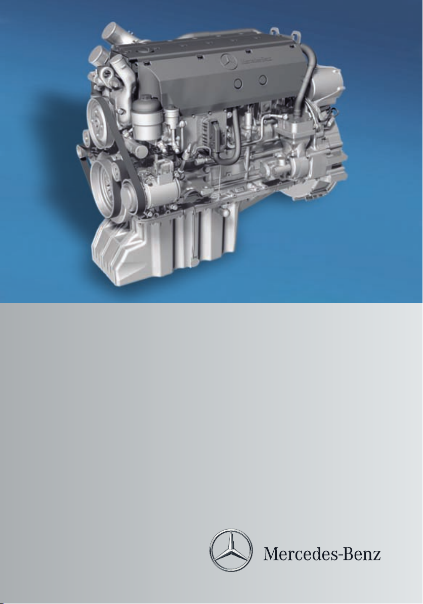
Engine control unit (engine resident)
The engine control unit is on the left side of
the engine.
These values are analysed together with data
the
from
engine sensors. They are compared
with the charts or characteristic curves
stored in the engine control unit.
Data from the sensors derives from, e.g.:
R
charge-air pressure and charge-air temperature
R
coolant temperature
R
fuel temperature
R
oil pressure
Start of injection, injection period and injection quantity are calculated on this basis and
the unit pump is controlled via the solenoid
valve accordingly.
®
If BlueTec® exhaust gas aftertreatment is
available, the associated sensors are also
analysed and the AdBlue®/DEF dosage is
controlled.
i
To obtain a replacement engine control
unit, you will require all the data on the
control unit type plate.
Example: OM 926 LA engine control unit
The engine control unit processes values
from the
FR (drive control) unit and the ADM.
These are, for example, the value from the
position sensor (accelerator pedal), the
engine brake or engine start/stop, etc.
Control unit type plate
:
Data record
;
Certification no.
=
Engine number
?
Equipment code

General information
23
FR (drive control) unit or ADM (on the
equipment)
The engine can be adapted to the various
operation-specific requirements
using the FR
(drive control) unit or the adaptation module
ADM.
Example: FR (drive control) unit
Various operation specific data such as
engine idling speed, maximum working
engine speed or speed limiter are stored in
the FR (drive control) unit or the ADM.
The FR (drive control) unit or the ADM
receives data from:
R
user (values from the position sensor,
engine start/stop)
R
engine brake switch
R
other systems (e.g. acceleration skid control)
R
engine control unit (e.g. oil pressure and
coolant temperature)
Values for the engine control (MR control
unit) are derived from this and conveyed via
the CAN line.
The FR (drive control) unit or the ADM controls various displays, e.g. the electronics
warning lamp, the engine brake and the constant throttle valve.
If the electronic engine control detects a
fault, the fault code is saved in the control
units. It
can be read out with the corresponding diagnostic testers (STAR DIAGNOSIS or
minidiag2).
In addition, the ^ electronics warning
lamp is switched on.
i
Mercedes-Benz diagnostic
testers can be
connected to the 14-pin diagnostic socket
on the equipment or with the EU compliant
service connector. Both fault memory and
stored engine data can be read out using
this equipment.
SCR frame module (on the frame)
SCR frame module
The SCR frame module reads signals and
transmits them
via the CAN line to the engine
control unit.
The following signals are read:
R
Temperature sensor upstream of the SCR
catalytic converter
R
Temperature sensor downstream of the
SCR catalytic converter
R
NOx sensor downstream of the SCR catalytic converter
R
Combination sensor for level and temperature in the AdBlue®/DEF tank
R
Combination sensor for humidity and air
charge temperature
Example: diagnostic socket
At a glance

General information
24
At a glance
Example: EU compliant service connector

Warning and indicator lamps
Engine, general
General information
25
Symbol
;
1
Reason for display/displayed message
Fault lamps Impermissible operating conditions
Text in the engine
symbol: "CHECK"
;
STOP lamp
Serious fault
2
Text in the engine
symbol: "STOP"
k
#
Electronic
engine control
malfunction
Charge current
(power generation)
Lights up in the event of an electronic engine control malfunction. Engine may only be operated in
emergency mode.
Lights up in the event of a charge current (power
generation) malfunction.
If the warning lamp does
not go out after starting the engine, or if it goes
on while the engine is running, the alternator or
poly-V-belt is faulty.
%
BlueTec® exhaust gas aftertreatment on-highway version
Cold-start aid Lights up if the cold-start aid is active.
3
The following indicator lamps could be available on the instrument panel:
Symbol
þ
1
Reason for display/displayed message
AdBlue®/DEF level
Fault message/action required
(warning before reduction in
operating performance)
;
È
NOx bulb
Engine indicator lamp Exhaust system fault
Reduction in operating perform-
Active torque limitation
ance
At a glance
1
Symbols may vary depending on the vehicle/equipment version.
2
In addition, a warning tone may sound.
3
On-highway: vehicles with MOT approval.

General information
26
BlueTec® exhaust gas aftertreatment off-highway version
4
The following indicator lamps could be available on the instrument panel:
Symbol
þ
1
Reason for display/displayed message
AdBlue®/DEF level
Fault message/action required (warning
before reduction in operating performance)
At a glance
!
È
lights up
Check engine/exhaust gas
aftertreatment
Torque/speed limiter
2
active
Fault and misuse (failure in the monitoring
system)
Slight reduction in operating performance
(level 1)
È
flashes
Significant reduction in operating performance
(level 2)
Continuous brake
If increased braking power is required, the
engine can be equipped with a brake valve
downstream from the exhaust gas turbocharger in
conjunction with constant throttle
valves.
OM 926 LA constant throttle valve
:
;
The brake valve uses exhaust back pressure
to increase braking power. The constant
throttle
OM 904 LA/OM 924 LA constant throttle valve
:
Constant throttle valve
;
Pneumatically-actuated line
compression pressure in the power stroke
(third stroke), whilst the compression (second stroke) is not significantly affected.
The constant throttle valve is an additional
valve in the cylinder head. When open, the
constant throttle valve establishes a connection between the combustion chamber and
4
Off-highway: vehicles without MOT approval.
1
Symbols may vary depending on the vehicle/equipment version.
2
In addition, a warning tone may sound.
Constant throttle valve
Hydraulically-actuated line
valves
bring about a reduction of the

General information
27
exhaust port. This brings about the desired
decompression during the power stroke.
When the engine brake is activated, the constant throttle valves are opened. For
OM 904/OM 924 engines, the actuation is
pneumatic. For OM 906/OM 926
engines,
the actuation is hydraulic. The brake valve on
the exhaust gas turbocharger is also closed.
The engine brake is actuated by the FR (drive
control) unit (Y page 23) or the ADM.
The engine brake is always deactivated below
900 rpm. This prevents the engine from stalling. The engine brake is automatically deactivated even if the position sensor (e.g. accelerator pedal) is in use.
i
In emergency mode (constant engine
speed), the engine brake can only be activated in overrun mode at increased engine
speed. Once the constant engine speed is
reached, the engine brake is automatically
deactivated again.
Cold-start aid
The cold-start
aid makes it easier to start the
engine at low outside temperatures (below
–15 †); it is activated when the outside temperature falls below –4 †.
Environmental note
H
At outside temperatures below about –4 †
the cold-start aid minimises emissions (after
starting
load on the starter motor and batteries and
enables the engine to be started more rapidly.
For this reason you should only start the
engine after the % indicator lamp goes out.
engine). In addition, it reduces the
the
The cold-start aid is automatically deactivated if:
R
the engine
is not started within 30 seconds
of the % indicator lamp going out.
R
the engine is started while the % indicator lamp is still lit.
R
the coolant temperature reaches around
0 † while the engine is running.
At a coolant temperature above approximately –4 †, the % indicator lamp goes
out after approximately 2 seconds (function
check). At a coolant temperature below
approximately –4 †, the % indicator lamp
goes out after approximately 20 seconds.
Have the cold-start aid checked and repaired
at a qualified specialist workshop. MercedesBenz recommends that you use a MercedesBenz or MTU Service Centre for this purpose
(Y page 11). Work relevant to safety or on
safety-related systems must be carried out at
a qualified specialist workshop.
At a glance
X
To activate the cold-start aid: turn the
vehicle key
to the drive position in the igni-
tion lock.
The % indicator lamp lights up in the
instrument panel.
X
After the % indicator lamp goes out,
start the engine within 30
seconds.
Z

28

Safety precautions .............................. 30
Staff qualifications ............................. 30
Organisational measures ................... 30
29
Safety

Organisational measures
30
Safety precautions
Damage to the engine can also lead to personal injury.
In order to avoid engine damage,
the following safety precautions must be
adhered to.
Safety
Safety precautions
R
Only start
the engine when the batteries
are firmly attached.
R
Do not disconnect the batteries when the
engine is running.
R
Do not use a rapid charger to start the
engine.
R
Only perform the jump-starting procedure with separate batteries.
R
Note, the battery terminals must be disconnected when rapid charging the batteries.
R
Observe the operating instructions of the
rapid battery charger.
R
Please note, when carrying out electric
welding work, that the batteries must be
disconnected and both of the cables ("+"
and "-") must be firmly attached to each
other.
R
The control unit connectors may only be
connected/disconnected when the electrical system is switched off.
R
Incorrect control unit-power supply
polarity (e.g. by connecting up the batteries incorrectly) can cause irreparable
damage to the control units.
R
Tighten diesel injection system connections to the prescribed tightening torque.
R
If temperatures above 80 † are to be
expected (e.g. in a drying oven), the control unit on the engine must be removed.
R
Only use the appropriate testing probes
when taking measurements from electrical connectors (e.g. a Mercedes-Benz
connection set). Telephones and twoway radio devices that are not connected
to an external aerial, can cause malfunc-
tions in the vehicle electronics and thus
endanger the operating safety of the
engine.
Staff qualifications
WARNING
G
If maintenance and repair work on the engine
is
carried out correctly, the operation and
not
safety may be affected, which can result in
accidents and personal injury.
Always have work on or modifications to the
engine carried out at a qualified specialist
workshop that has the necessary special
skills and tools for the work required.
Mercedes-Benz recommends a MercedesBenz or MTU Service Centre.
The engine should only be operated, maintained and repaired by trained personnel who
have been briefed and authorised by the operator. The minimum legal age for personnel
carrying out maintenance and repair work
must be observed.
Organisational measures
The responsibilities for operation, maintenance and
repairs are to be determined by the
operator. Give the Operating Instructions and
the Maintenance Booklet to the personnel
that are charged with operating or carrying
out work on the engine.
WARNING
G
Before operating the engine, please read
these
Operating
read the operating instructions of the vehicle
or the machine to which the engine is fitted.
You may not recognise dangers and may
injure yourself or others.
Instructions. Please also first
Instruct personnel on how to operate the
engine using the Operating Instructions.
When doing so, put special emphasis on
safety-relevant information. This is particu-

larly important for personnel that only work
occasionally on the engine.
Always keep the Operating Instructions and
the Maintenance Booklet readily accessible,
in the area of engine operation.
In addition to the Operating Instructions,
other general, country-specific, legal and
other binding
tion and environmental protection must be
adhered to.
regulations on accident preven-
Organisational measures
31
Safety
Z

32

Operation ............................................. 34
Continuous brake ................................ 40
Driving tips .......................................... 40
Refuelling ............................................. 41
Winter operation ................................. 43
33
Driving mode/working mode

Operation
34
Operation
Preparation for operation
At the factory, the engine is filled with 5W30
initial operation oil that complies with Sheet
225.6 of the Mercedes-Benz Specifications
for Service Products.
These high-quality engine oils are beneficial
running-in process. They also allow you
to the
to make the first oil change in accordance
with the applicable oil change intervals for
normal operation. This eliminates the need
for special initial operation oils and the additional oil change otherwise required.
The extended maintenance intervals can only
be observed if engine oils complying with
Sheet 228.5 of the Mercedes-Benz Specifications for Service Products are used.
Driving mode/working mode
X
If the engine is at normal operating temperature: wait about one minute. If the
engine is
X
Check the engine oil level with oil dip-
cold: wait about 5 to 10 minutes.
stick ;. The oil level should be between
the upper and lower marks on oil dipstick ;.
X
If necessary, add oil via filler neck :.
Do not add too much oil when topping up.
Topping up with too much oil can result in
damage to the engine or the catalytic converter. Drain or siphon off excess oil.
Adding coolant
X
Information on coolant mixture ratio
(Y page 76).
X
Filling the cooling system (Y page 48).
Refuelling
Use summer or winter fuel depending on the
season (Y page 50).
!
When refuelling ensure that conditions
are clean and do not allow water to enter
the tank and thus contaminate the fuel.
Example: OM 926 LA
:
Filler neck
;
Oil dipstick
Engine oil level
Check the engine oil level on a regular basis,
e.g. every week or each time you refuel.
X
Park the vehicle/equipment on a horizontal
surface.
X
Engage the parking brake.
X
Switch off the engine.
Refuelling with AdBlue®/DEF
Only use AdBlue®/DEF that complies with
DIN 70070/ISO
22241. Do not use any additives. If AdBlue®/DEF comes into contact
with painted or aluminium surfaces when filling the tank, rinse the affected surfaces
immediately with plenty of water.
Bleeding the fuel system
The bleeding of a fuel system that has been
run dry takes place when the engine is next
started
refuelling. Automatic continuous
after
bleeding takes place in the filter.
i
The battery must be sufficiently charged
when the engine is started in order for the
fuel system to be bled.

i
Use the integrated hand pump
(Y page 68) to bleed the heated-fuel prefilter with
water separator mounted on the
vehicle or equipment.
Starting the engine for the first time
Preparation
Carry out the work listed under "Preparing for
operation" before operating the engine for
the first time (Y page 34).
Observe the information contained in the
equipment/vehicle manufacturer's
operating
instructions.
X
Connect a power supply.
X
Switch on the ignition.
X
Start the engine using the key in the ignition
lock or the start button on the engine. Do
not depress the accelerator or clutch pedal
while doing so. For equipment, the neutral
position must be engaged.
As a safety function, the electronic engine
control system facilitates the possibility of
only allowing the engine to be started when
the transmission or equipment is in neutral.
WARNING
G
Make sure you do not touch any hot or moving
engine components (e.g. exhaust manifold,
poly-V-belt, fan) when the engine is running.
You could injure yourself.
Be aware of the road and traffic situation
when working on public roads and secure
your position accordingly.
WARNING
G
There is a danger of limbs being caught, pulled
in
thereby crushed or severed by rotating
and
engine parts.
Operation
Therefore you should:
R
R
R
G
When opening the coolant expansion tank,
there is a risk of scalding due to hot coolant
spraying
expansion tank are pressurised when the
engine is at operating temperature. Wear
gloves and eye protection.
Only open the coolant expansion tank when
the coolant temperature is below 50 †.
G
Coolant contains glycol and is therefore toxic.
Do not swallow the coolant. See a doctor
immediately if you swallow coolant.
Make sure that coolant does not come into
contact
contact with eyes, rinse immediately with
plenty of clean water. Clean affected areas of
skin and clothing with soap and water immediately. Change any affected clothing immediately.
Starting the engine for the first time
X
To check coolant level: leave the engine
running at a moderate engine speed for
around five minutes.
X
If the coolant temperature is less than
50 †, check the coolant level again. Add
coolant.
If a heating system is connected to the cooling system, all heating system valves must be
opened while the cooling system is being topped up. Otherwise, there might be too little
safe distance between yourself and
keep a
rotating engine parts, including when the
engine is being started.
wait until all engine parts have stopped
moving before carrying out any work on the
engine.
wear work clothing which is fastened and
close-fitting. Wear a hair net if necessary.
Remove jewellery such as watches and
necklaces.
WARNING
The cooling system and coolant
out.
WARNING
skin, eyes or clothing. In case of
with
35
Driving mode/working mode
Z

36
Operation
coolant in the coolant circuit after it is filled.
Only close
the heating system valves once the
engine has been running for a brief period
and, where applicable, the coolant has been
topped up.
X
Check the engine for leaks.
X
Check all hose fittings, hose clamps and
pipe connections on the engine as well as
the oil feed and return lines on the exhaust
gas turbocharger for leaks and firm seating.
X
Around five minutes after switching off the
engine, check the engine oil level with the
dipstick.
The oil level should be between the upper
and lower marks on the dipstick.
X
Check the seating of the bracket secured
to the engine.
X
Check the tightness of bolts on the exhaust
manifold, engine mountings, coolant pump,
starter motor and air compressor.
Driving mode/working mode
Starting and stopping the engine with
the key
X
To start the engine: turn the key in the
ignition lock to drive position 2.
X
Vehicles/equipment with a hot-water auxiliary heater: preheat the engine at outside
temperatures below −20 † before starting.
X
Vehicles/equipment with cold-start aid:
wait until the % indicator lamp in the
instrument cluster goes out.
X
Turn the key to start position 3 in
the ignition lock. While doing so, do not depress
the accelerator pedal. For equipment, keep
the idling function active.
X
When the engine has started, release the
key.
Depending on the vehicle/equipment, the
idling speed is automatically adjusted to
around 600 rpm. Depending on the nature
work to be performed, higher engine
of the
idling speeds are also possible.
X
If the engine does not start, interrupt the
starting procedure after no more than
30 seconds.
X
Turn the key in the ignition lock back to the
stop at key position g.
X
Repeat the starting procedure after approximately
X
After three starting attempts, wait approx-
one minute.
imately three minutes before trying again.
X
Observe the oil pressure gauge immediately after having started the engine.
Example: ignition lock
g
To insert/remove the vehicle key
1
Steering unlocked/radio position
2
Drive position (ignition)
3
Start position
X
Secure the vehicle/equipment against rolling away.
X
Shift the transmission to neutral or engage
neutral on the equipment.
!
After starting the engine, let it run at
engine idling
speed until the oil pressure is
displayed. If no oil pressure is displayed
after approximately 10 seconds, switch off
the engine. Determine the cause. The operating safety of the engine is jeopardised.
Starting and stopping the engine with
the start/stop button
X
Switch on the ignition.
X
Shift to neutral.
i
The start
button will not function if a gear
is engaged or the equipment is in an operating position.

Operation
37
Engine with one button
X
To start the engine: press
start/stop but-
ton :.
The engine starts and runs at engine idling
speed.
X
To start the engine and increase the
engine speed: press and hold start/stop
button :.
The engine
starts and runs at engine idling
speed. After about three seconds, the
engine speed increases.
X
Hold down start/stop button : until the
desired engine speed is reached.
After releasing start/stop button :, the
engine
continues
to run at the currently set
speed. The engine speed can be increased
up to the limiting speed.
X
To stop the engine: press start/stop button : again.
The engine switches off.
X
To start the engine: press start button ;.
The engine
starts and runs at engine idling
speed.
X
To increase the engine speed: while the
engine is running, press start button ;
again and hold it down until the desired
engine speed is reached.
After releasing start button ;, the engine
run at the currently set speed.
continues
to
The engine speed can be increased up to
the limiting speed.
X
To stop the engine: while the engine is
running, press stop button :.
The engine switches off.
X
To turn the engine over without starting
it: press and hold start button ; and stop
button : at the same time.
The engine turns over without starting.
X
Release start button ; and stop button :.
The engine remains at a standstill.
Operational monitoring
Charge current
The charge current indicator lamp must go
out after the engine has started.
Driving mode/working mode
Engine with two buttons
Example: charge current indicator lamp
If the #
indicator lamp does not go out, or
if it lights up while the engine is running,
switch off the engine and check the poly-Vbelt.
Z

38
Operation
!
Make sure that the poly-V-belt contact
surfaces are not damaged (e.g. torn), oily
or glazed, as this could cause the poly-Vbelt to slip. Do not run the engine without
a poly-V-belt.
Otherwise, the alternator and
coolant pump are not driven, which results
in engine damage.
Further information can be found in the
“Checking the poly-V-belt for wear”
(Y page 66) and “Replacing the poly-V-belt”
sections (Y page 97).
Electronic engine control
The electronics warning lamp must go out
after the engine has started.
Driving mode/working mode
Example: electronics warning lamp
If the electronics warning lamp does not go
out, or if it lights up while the engine is running, there is a malfunction in the electronic
engine control system.
Each malfunction
its own fault code. Temporary faults are also
stored.
Fault codes can be read using the MercedesBenz diagnostic tester STAR DIAGNOSIS or
minidiag2 (Y page 8). If the electronics warning lamp lights up while the engine is running,
read or determine the fault code.
is stored in the system with
Oil pressure
!
Once the
operating temperature has been
reached, the engine oil pressure may not
drop below the following values:
R
2.5 bar at rated speed
R
0.5 bar at idling speed
If the oil pressure falls below these values,
stop the engine and trace the cause.
Operating restrictions with on-highway
applications
The electronics monitor:
R
the display, level and quality of the
AdBlue®/DEF reducing agent
R
the efficiency of the catalytic converter in
accordance with the permitted thresholds
for nitrogen oxide emissions (NOx).
Requirements for vehicles
The engine output can be automatically
the
reduced
first time the vehicle is stationary
if:
R
the AdBlue®/DEF reservoir is empty
R
the permitted thresholds for nitrogen oxide
(NOx) emissions are exceeded.
Torque reduction
If the AdBlue®/DEF is used up or if there is a
fault, the indicator lamp in the instrument
panel lights up or flashes. The display also
shows a message. The engine output is only
reduced after a fault is detected and confirmed after up to four journeys.
The degree of torque reduction depends on
the vehicle category:
R
vehicles above 7.5 t: torque reduction by
approximately 40%
R
vehicles below 7.5 t: torque reduction by
approximately 25%
Fault in the monitoring system
If a fault is detected in the electronic monitoring of the exhaust gas aftertreatment sys-

Operation
39
tem, the torque is reduced automatically after
36 operating hours of the engine.
Operating restrictions for off-highway
engines
Minor operating restriction
The available torque is reduced within a
period of 10 minutes. The torque is reduced
across the entire engine speed range to 80%
of the maximum torque (see the diagram
below).
Reduction in output during minor operating restriction
Major operating restriction
The transition between a minor and a major
operating restriction
is achieved by a gradual
reduction in engine speed and torque. The
reduction takes place over a period of 60
minutes.
R
The engine torque is reduced from 80% of
the rated value by 1% per minute to 20% of
the rated value.
R
Simultaneously, the engine speed is
reduced over the period of 60 minutes from
the initial value to 1000 rpm.
Emergency override
A button is optionally available for overriding
the operating restriction in an emergency.
The override function makes the full engine
output available for up to 30 minutes and can
be used a maximum of three times. The override can only be activated between the start
of the operating restriction system and the
end of the major operating restriction. The
override function is also used to reset the
operating restriction after the fault is corrected. This
is the case, for example, after filling
up with AdBlue®/DEF of the correct quality.
Deleting the fault memory
A fault stored in the fault memory because of
the operating restriction system cannot be
deleted with a conventional reading device.
Faults can only be deleted using the Daimler/
MTU maintenance system.
Repeated violations
In the event of repeated violations, the periods for the trigger signals and continuous
reduction are shortened. When a fault is eliminated (for example the NOx sensor is
replaced or reconnected), the operating
restrictions are reset. Normal operation can
be resumed. If a fault occurs again because
of the operating restriction system within
40 hours, the periods of the operating restriction system are shortened.
Example: if a fault reoccurs within 40 hours
of the first elimination, the time until the operating restriction comes into effect is halved.
If the same fault occurs within 40 hours of the
second fault being rectified, the times are
shortened to a quarter.
Stopping and switching off the engine
WARNING
G
When switching off the equipment or parking
the vehicle, make sure that the exhaust system does not come into contact with combustible objects, e.g. dry leaves, grass or
other highly flammable materials.
X
Park the vehicle/equipment.
X
Secure the vehicle/equipment against rolling away.
X
Shift the transmission into neutral/decouple the drive system.
Z
Driving mode/working mode

40
Driving tips
Let the engine idle for approximately two
minutes before switching off the engine if:
R
the coolant temperature is very high (over
90 †).
R
the engine
X
To switch off the engine: turn the vehicle
has been operated at full output.
key in the ignition lock back to the stop at
position u.
X
Press the start/stop button on the engine
or on the engine shutoff device on the
equipment.
X
Safeguard the vehicle/equipment against
rolling away.
!
Stop the engine immediately if:
R
the oil pressure falls or fluctuates significantly.
R
the power output or engine speed
decreases and the position of the position sensor (accelerator) remains constant.
Driving mode/working mode
R
heavy smoke is emitted from the
exhaust.
R
the coolant or engine oil temperature
rises steeply.
R
abnormal noises suddenly come from
the engine or exhaust gas turbocharger.
i
When you switch off the engine, BlueTec® exhaust gas aftertreatment automatically
the exhaust system with fresh
flushes
air. Residues of AdBlue®/DEF on the
metering unit or the injection nozzle might
otherwise impair the function of BlueTec
exhaust gas aftertreatment. Depending on
the engine's previous operating load, BlueTec® exhaust gas aftertreatment may flush
the exhaust system several times.
When BlueTec® exhaust gas aftertreatment
flushes the exhaust system, an air valve is
activated. You may then hear a hissing
sound. This hissing sound does not indicate
a leak in the compressed-air system.
Continuous brake
The airbrake
and the constantly open throttle
valves are employed as continuous brakes.
WARNING
G
Do not activate the continuous brake (engine
brake/retarder) on slippery road surfaces.
The wheels may otherwise become locked
and the vehicle could skid.
You can utilise the engine's braking effect,
particularly
R
activate the continuous brake
R
shift to a lower gear in good time
long downhill gradients, if you:
on
Driving tips
Running-in
Equipment
Observe the equipment manufacturer's running-in notes.
Vehicles
The running-in period of the engine has a significant effect on the vehicle, especially for
the:
R
service life
R
operating reliability
R
economy
Observe the following notes during the run-
®
ning-in period up to 2000 km (30 operating
hours):
R
avoid subjecting the engine to full load.
R
run-in the engine with care using differing
speeds and engine revs.
R
avoid high engine revs.
R
do not drive at more than ¾ of the maximum road speed for each gear.
R
change gear in good time.
R
do not shift down to brake the vehicle.
R
in the case of vehicles with automatic
transmission, do not press the accelerator

Refuelling
41
pedal beyond the point of resistance (kickdown) and only engage the shift ranges 4,
3, 2, or 1 when driving slowly.
After 2000
km (30 operating hours), you can
gradually bring the vehicle up to full road and
increased engine speeds.
Fuel consumption
General information
Fuel consumption depends on:
R
the type
of fuel used (diesel fuel, fatty acid
methyl ester FAME fuel)
R
the machine version
R
the operating mode
R
the operating conditions
R
the attached equipment (e.g. hydraulic
pumps, mowers, etc.)
For these reasons, exact details about any
single engine's fuel consumption cannot be
provided.
Machine version
The following components influence fuel consumption:
R
tyres (e.g. tyre pressure, tyre condition)
R
body type
R
drive train (e.g. transmission ratio)
R
additional equipment (e.g. automatic climate control, auxiliary heating)
Operating mode
Your operating mode can help to keep the fuel
consumption down:
R
anticipate road and traffic conditions.
R
avoid frequent acceleration and braking.
R
stay within the economical engine speed
range.
Operating conditions
Fuel consumption can increase due to poor
operating conditions.
Observe the following notes:
R
avoid driving in mountainous terrain.
R
do not allow the engine to idle when the
vehicle is stationary.
R
do not drive with unnecessary weight.
R
avoid frequent cold starts.
R
avoid frequent short journeys.
AdBlue® consumption
AdBlue®/DEF consumption
is between 4 and
8% of the fuel consumption, depending on
engine use.
Engine oil consumption
After running in the engine, oil consumption
may reach 0.5% of the vehicle's fuel consumption.
More arduous operating conditions and
increased distance covered could result in
engines exceeding this oil consumption
value.
Refuelling
Fuels
Important safety notes
WARNING
G
Fuel is highly flammable. Therefore, fire,
naked flames and smoking are prohibited
when handling fuel.
Deactivate the auxiliary heating when refuelling to prevent fuel vapours from igniting on
the auxiliary heating exhaust system.
Fuel is toxic and constitutes a health hazard.
Therefore, you should make sure that:
Driving mode/working mode
Z

42
Refuelling
R
fuel does not come into contact with skin,
eyes or clothing.
R
you do not inhale fuel vapours.
R
children are kept away from fuel.
If you or anyone else comes into contact with
fuel:
R
wash eyes immediately with plenty of clean
water if fuel comes into contact with the
eyes and consult a doctor.
R
clean affected areas of skin with soap and
water immediately.
R
change out of clothing which has come into
contact with fuel immediately.
R
if fuel is swallowed, a doctor should be consulted immediately.
WARNING
G
Do not use petrol to refuel vehicles with a diesel
would result in damage to the fuel system and
engine, which could lead to a vehicle fire.
Driving mode/working mode
!
AdBlue®/DEF is not a fuel additive and
Do not mix diesel with petrol. This
engine.
must not be added to the diesel tank. If
AdBlue®/DEF gets into the diesel tank, this
could lead to engine damage.
!
Do not use petrol to refuel vehicles with a
diesel engine. Even small amounts of petrol
result in damage to the fuel system and
engine.
!
If you fill the tank with the wrong fuel by
accident, do not start the engine. Otherwise, the fuel lines may be contaminated.
Notify a qualified specialist workshop and
have the fuel tank and fuel lines fully
drained.
!
Do not add any special fuel additives to
the diesel fuel or fatty acid methyl ester
FAME fuel.
Special fuel additives can lead to:
R
malfunctions
R
damage to the catalytic converter
R
engine failure
You will find further information on fuel in the
"Service products" section (Y page 50).
Environmental note
H
If fuels are handled improperly, they pose a
danger to persons and the environment. Do
not
the surface waters, the ground water or into
the ground.
fuels to run into the sewage system,
allow
Before filling the tank
X
Switch off the engine.
X
Secure the vehicle/equipment against rolling away.
X
Switch off the auxiliary heating system.
X
Observe the fuel grade (Y page 50).
!
If you are refuelling the vehicle from
drums or canisters, filter the fuel before
refuelling.
This prevents malfunctions in the fuel system caused by contaminated fuel.
i
Regularly check
the fuel prefilter with the
heated water separator for condensation
(Y page 86).
AdBlue®/DEF
Important safety notes
WARNING
G
If the AdBlue®/DEF tank
temperatures, ammonia vapours may escape.
Ammonia vapours have a pungent odour and
particularly irritate:
R
skin
R
mucous membranes
R
eyes
The vapours may cause a burning sensation
in the eyes, nose and throat as well as irritation of the throat and watering eyes.
Avoid inhaling ammonia vapours.
cap is opened at high

Winter operation
43
WARNING
G
AdBlue®/DEF must not come into contact
with skin, eyes or clothing.
R
If AdBlue®/DEF comes into contact with
your eyes
clean water immediately.
R
If AdBlue®/DEF is swallowed, immediately
rinse your mouth out with a lot of clean
water and drink plenty of water.
R
Change clothing that is soiled with
AdBlue®/DEF immediately.
R
If allergic reactions occur, consult a doctor
immediately.
Keep AdBlue®/DEF out of the reach of children.
!
The BlueTec® exhaust gas aftertreatment
or skin, rinse affected areas with
will cease to function correctly if you:
R
fill the AdBlue®/DEF reservoir with
cleaning agent or other service products
or fuels
R
mix in additives
R
dilute AdBlue®/DEF
Only use AdBlue®/DEF in accordance with
DIN 70070/ISO 22241.
Notify a qualified specialist workshop in the
event of incorrect filling.
You will find further information on AdBlue®/
DEF in the "Service products" section
(Y page 54).
Environmental note
H
Dispose of AdBlue®/DEF in an environmentally responsible manner.
Before filling the tank
X
Switch off the engine.
X
Secure the vehicle/equipment against rolling away.
X
Switch off the auxiliary heating system.
Bleeding the fuel system
If the fuel system is run dry, the system will
be bled the next time the engine is started
after refuelling. Automatic continuous bleeding takes place in the filter.
The battery
must be sufficiently charged during the starting procedure to ensure that the
fuel system can be bled.
Bleed the heated fuel prefilter with water separator mounted on the vehicle or equipment
using the integrated hand pump
(Y page 86).
Winter operation
Cold-start aids
The following
notes should be observed at the
start of the cold season.
Fuel
WARNING
G
There is an increased risk of fire when handling
fire, naked flames and sparks, and refrain
from smoking when handling fuels.
as they are highly flammable. Avoid
fuels
Use cold-resistant diesel fuel (Y page 50).
Jump-starting
WARNING
G
The use of liquid or gaseous starting aids can
cause explosions. This may result in severe
injuries.
Do not use liquid or gaseous starting aids
such
as
ether or Startpilot to start the engine.
Engine oil
When changing the oil, select an engine oil
that is
compatible with the SAE classification
and the outside temperatures expected during the period of use (Y page 46).
Driving mode/working mode
Z

Winter operation
44
Coolant
WARNING
G
When opening the coolant expansion tank,
there is a risk of scalding due to hot coolant
spraying out.
expansion tank are pressurised when the
engine is at operating temperature. Wear
gloves and eye protection.
Only open the coolant expansion tank when
the coolant temperature is below 50 †.
WARNING
G
Coolant contains glycol and is therefore toxic.
Do not swallow the coolant. See a doctor
immediately if you swallow coolant.
Make sure that coolant does not come into
contact with
contact with eyes, rinse immediately with
plenty of clean water. Clean affected areas of
skin and clothing with soap and water immediately. Change any affected clothing imme-
Driving mode/working mode
diately.
The cooling system and coolant
skin, eyes or clothing. In case of
Check the antifreeze protection properties of
the coolant in good time and increase the
antifreeze/corrosion inhibitor concentration
if necessary (Y page 48).
Batteries
WARNING
G
Comply with safety precautions and take protective measures when handling batteries.
Risk of explosion
Fire, naked flames and
smoking are prohibited
when handling the battery.
Avoid creating sparks.
Battery acid is caustic.
Avoid contact
eyes or clothing.
Wear suitable protective
clothing, in particular
with the skin,
gloves, an apron and a face
mask.
Immediately rinse acid
splashes off with clean
water. Consult a doctor if
necessary.
Wear eye protection.
Keep children away.
Observe this Owner's Manual.
Always aim to achieve the full charge status.
You can do this by means of careful maintenance and low electrical consumption. The
cold start capacity is reduced when it is very
cold. For example, at -10 † it is only around
60 % of the normal capacity.
Notes
when the engine is out of use
for
If the engine/vehicle/equipment is to be out
of use for longer than three weeks, disconnect the
negative terminal on the battery. This
prevents the batteries from being discharged
by no-load current consumers. If the engine/
vehicle/equipment is to be out of use for a
longer period, remove the batteries and store
them in a dry, well-ventilated area. Recharge
the batteries:
R
before operating the engine/vehicle/
equipment again or
R
at least every three months for longer periods of disuse.
If the engine/vehicle/equipment is out of use
for a long period, store the batteries in a
heated area if possible. Ensure good ventilation when recharging. Refer to the "Decommissioning the engine" section
(Y page 80) for further information.

Service products ................................. 46
Cleaning and care ............................... 55
Maintenance ........................................ 56
45
Maintenance and care

Service products
46
Service products
Introduction to service products
WARNING
G
Service products are hazardous to health.
They contain toxic and caustic substances.
Service products are highly flammable.
For
reason, observe the following instruc-
this
tions to prevent injuries to yourself and others:
R
Do not inhale the vapours. When indoors,
always ensure there is sufficient ventilation
to prevent intoxication.
R
Do not let service products come into contact with skin, eyes or clothing. Should contact occur, however, clean the affected
areas of skin with water to prevent caustic
burns and other injuries.
In the event of eye contact, wash eyes thoroughly with plenty of clean water.
Maintenance and care
R
Fire, naked flames and smoking are forbidden when handling service products due to
their high flammability.
R
Observe the usage and warning notices on
the containers.
The use of approved service products is an
integral part of the implied warranty.
!
Special additives (except approved fuel
additives) are neither required nor
approved for use with approved service
products. Additives could cause damage to
the assemblies. Therefore, do not mix any
additives with service products.
You are responsible for the results of using
fuel additives.
Environmental note
H
Dispose of service products in an environmentally-responsible manner.
Service products are, for example:
R
fuels (e.g. diesel)
R
lubricants, e.g. engine and transmission
oils, hydraulic fluids, greases
R
antifreeze, coolant
R
AdBlue®/DEF
(BlueTec®
exhaust gas after-
treatment reduction agent)
Approved service products fulfil the highest
quality standards and are documented in the
Mercedes-Benz Specifications for Service
Products. Damage caused by the use of
service products that have not been approved
invalidates the implied warranty. For this reason, only use service products that have been
approved for your engine.
You can recognise service products approved
by Mercedes-Benz by the following inscription on the container:
R
MB Approval (e.g. Approval 228.5)
or
R
MB Approval 228.5
Other labels and recommendations relating
to the quality or indicating that the product
meets a certain specification are not necessarily approved by Mercedes-Benz. Further
information is available from any MercedesBenz or MTU Service Centre (Y page 11).
i
Information about service products that
have been tested and approved by
Mercedes-Benz for your engine is available
online at http://bevo.mercedes-
benz.com/
i
The specification and availability of lubricants may vary. Individual lubricants may
no longer be available, especially for older
engines. Information is available from any
Mercedes-Benz or MTU Service Centre
(Y page 11).
Engine oils
Notes on engine oils
Only use engine oils that comply with the
Mercedes-Benz Specifications for Service
Products.

Service products
47
The following engine oils are approved:
R
Sheet no. 228.5 / 228.3 standard quality
multi-grade engine oils
R
Sheet no. 228.51 / 228.31 low-ash multigrade engine oils
R
Sheet no. 228.2 standard quality singlegrade engine oils
R
Sheet no. 225.6 multi-grade engine oils,
initial operation oils
!
Engine oils
of a different quality grade are
not permissible and may damage the
engine.
Mercedes-Benz particularly recommends
engine oils that comply with Sheet no. 228.5
of the Mercedes-Benz Specifications for
Service Products.
These engine oils are of a high standard of
quality and have a beneficial effect on:
R
engine wear
R
fuel consumption
R
exhaust emissions
The maximum interval for oil change is only
achieved with engine oils of a particularly high
quality grade.
i
You can find information on the quality
grade, e.g. Sheet no. 228.5, and the viscosity, e.g. SAE class 5W-30, from the designation on the oil container.
Scope of use
For engines in vehicles/equipment operating
with diesel fuel, only use multi-grade engine
oils compliant with Sheet no. 228.5 /
228.51 / 228.3 / 228.31 or single-grade
engine oils compliant with Sheet no. 228.2.
For engines without BlueTec® exhaust gas
aftertreatment, multi-grade oils compliant
with Sheet no. 228.1 and single-grade oils
compliant with Sheet no. 228.0 can also be
used.
For vehicle/equipment operation with FAME
fatty acid methyl ester fuel (bio-diesel fuel),
only use engine oils compliant with Sheet no.
228.5 / 228.51 / 228.3 / 228.31.
For engines without BlueTec® exhaust gas
aftertreatment, oils
compliant with Sheet no.
228.1 can also be used. This is also required
for a mixture of conventional diesel fuels and
FAME fatty acid methyl ester fuels (bio-diesel
fuel).
Multi-grade engine oils compliant with Sheet
no. 228.5 / 228.51 / 228.3 / 228.31 / 228.1
can be used throughout the year. Depending
on the fuel quality (fuel sulphur content or
FAME fatty acid methyl ester fuel), the oil
change intervals may be shortened. For
details, see the Maintenance Booklet.
Single-grade engine oils compliant with Sheet
no. 228.2 / 228.0 only cover an SAE class
(viscosity) for a certain temperature range.
Change the engine oil to an SAE class suitable
for the time of year and the respective outside
temperatures.
The use of low-ash engine oils is permissible
but not essential. When low-ash engine oils
compliant with Sheet no. 228.51 and 228.31
are used, a low-sulphur diesel fuel (less than
50 ppm, 0.005 % by weight) should be used.
If this low-sulphur diesel fuel is not available,
standard oils compliant with Sheet no.
228.5 / 228.3 / 228.2 should be used.
Oil change
Oil change intervals are dependent on the following:
R
the operating conditions of the vehicle
R
the grade of the engine oil used
R
the fuel grade (sulphur content)
R
the fuel type, e.g. FAME fatty acid methyl
ester fuel
For more
details, see the Maintenance Book-
let.
!
If you do not use oil for all-year-round
operation in your engine, change the
engine oil right at the beginning of the cold
season. Use only an approved engine oil in
the specified SAE classification.
Maintenance and care
Z

Service products
48
If the SAE class (viscosity) of the engine oil
used is
not suitable for continually low outside temperatures below −20 †, this could
cause engine damage.
The specified temperatures of the SAE
class always refer to freshly added oil.
Engine oil ages during driving due to soot
and fuel residue. This impairs the characteristics of the engine oil, particularly at low
outside temperatures.
Mercedes-Benz strongly recommends that,
at outside temperatures below −20 †, you
use engine oils of SAE class 5W-30.
Maintenance and care
Engine oil SAE classes (viscosity)
:
Single-grade engine oils
;
Multi-grade engine oils
X
Select the SAE class of engine oil in accordance with outside temperatures.
i
You can only achieve the maximum oil
change intervals by using engine oils of
high
particularly
with Sheet no. 228.5 of the Mercedes-Benz
Specifications for Service Products).
Environmental note
H
If you operate your vehicle using FAME fatty
acid
methyl
cautions must be taken and national specifications complied with when disposing of
quality (e.g. in accordance
ester fuel (bio-diesel), special pre-
engine oils. Information is available from any
Mercedes-Benz or MTU Service Centre.
Adding/topping up the engine oil
Do not add too much oil. If you add too much
engine or the catalytic converter could
oil, the
be damaged. Drain or siphon off any excess
oil.
When topping up, Mercedes-Benz recommends that you only use engine oil of the
same grade and SAE class as the oil filled at
the last oil change.
Check the oil level before topping up the
engine oil (Y page 34).
You can find more information on topping up
the engine oil in the “Changing the engine oil
and filter” section (Y page 62).
Miscibility of engine oils
The benefits of high-quality engine oils are
diminished if you mix them.
Engine oils are differentiated according to:
R
engine oil brand
R
quality grade (Sheet no.)
R
SAE viscosity class
If, in exceptional circumstances, the type of
engine oil currently used in the engine is not
available,
another
mineral or synthetic engine
oil may be used. Make sure it is approved for
Mercedes-Benz.
Observe the notes in the Service Booklet.
Coolants
Coolant additive with antifreeze properties
The coolant is a mixture of water and corrosion inhibitor/antifreeze.

Service products
49
The corrosion inhibitor/antifreeze in the coolant has the following properties:
R
anti-corrosion protection
R
antifreeze protection
R
increases the boiling temperature
Leave the
coolant in the engine all year round
in order to prevent corrosion and to increase
the boiling point. Also do this in countries with
hot outside temperatures.
Check the corrosion inhibitor/antifreeze concentration in the coolant every six months.
Only use approved corrosion inhibitor/antifreeze agents.
Topping up coolant
When topping up, only use prepared coolant
with 50% by volume corrosion inhibitor/antifreeze agent.
Before topping up, observe the quality of the
corrosion inhibitor/antifreeze agent in the
cooling system (Sheet no.). Corrosion inhibitors/antifreeze agents compliant with Sheet
325.3 and 326.3 must not be mixed with
those of Sheet 325.0/2 or 326.0/2.
Only top up using a corrosion inhibitor/antifreeze agent of the same quality grade.
Miscibility of corrosion inhibitor/antifreeze agents
!
Corrosion inhibitors/antifreeze agents
that comply with Sheet 325.3 and 326.3
must not be mixed with those of Sheet
325.0/2 or 326.0/2. This prevents damage to the engine cooling system.
Renewing coolant
Coolant change with antifreeze protection:
R
every three years if using corrosion inhibitor/antifreeze agent compliant with Sheet
325.0/2 and 326.0/2
R
every five years if using corrosion inhibitor/
antifreeze agent compliant with Sheet
325.3 and 326.3
Coolant change with corrosion inhibitor/antifreeze agent compliant with Sheet 325.3,
326.3: before adding this corrosion inhibitor/
antifreeze agent, the cooling system must
first be flushed (Y page 76).
When renewing the coolant, ensure that it
contains 50% by volume of corrosion inhibitor/antifreeze agent. This corresponds to
antifreeze protection down to −37 †.
Do not exceed 55% by volume (antifreeze protection down to approximately −45 †). Heat
dissipation properties are otherwise
impaired.
The water in the coolant must meet certain
requirements, which are often fulfilled by
drinking water. The water must be treated if
its quality does not meet the required standards.
Please note the Mercedes-Benz Specifications for Service Products, Sheet number 310.1.
Further information about operating and road
safety for your engine/vehicle/equipment is
available from any Mercedes-Benz or MTU
Service Centre (Y page 11).
Coolant additive without antifreeze properties
If your vehicle does not need antifreeze protection, e.g. in countries with consistently
high outside temperatures, you can, as an
exception, use a coolant additive.
Instead of corrosion inhibitor/antifreeze
additive, add a coolant additive compliant
with Sheet number 312.0 of the MercedesBenz Specifications for Service Products to
the water.
Improvers (corrosion-inhibiting oils) are not
permitted.
Renew the coolant annually.
Further information about the required water
quality and approved coolant additives without antifreeze protection is available from any
Mercedes-Benz or MTU Service Centre
(Y page 11).
Maintenance and care
Z

Service products
50
Diesel fuels
Important safety notes
WARNING
G
Fuel is highly flammable. Fire, naked flames
and smoking as well as the use of auxiliary
heaters (sparks) are therefore prohibited
when handling fuel.
Switch off
before refueling.
G
Avoid contact with fuels.
It is hazardous to your health if your skin
comes into direct contact with fuels or you
breathe in fuel vapours.
!
refuel the engine/vehicle/equipment, you
should filter the fuel before filling.
Maintenance and care
This prevents malfunctions in the fuel system caused by contaminated fuel.
!
diesel vehicle fuel that complies with the
European standard EN 590.
EN 590
maximum sulphur content of 10 ppm. However, it is also permitted to operate engines
with BlueTec® exhaust gas aftertreatment
with up to 50 ppm.
For engines without BlueTec® exhaust gas
aftertreatment, the maintenance intervals
must be reduced when operating with
higher sulphur contents. For details on this,
see the table below. Even if the maintenance intervals are reduced, operation with
higher sulphur contents will lead to
increased engine wear, especially on the
fuel injectors.
When necessary, use only approved fuel
additives.
There is otherwise a risk of impaired engine
performance or engine and catalytic converter damage. The use of appropriate fuel
additives is your responsibility.
the engine and the auxiliary heating
WARNING
If you are using drums or canisters to
Only refuel with commercially available
describes a sulphur-free fuel with a
!
Fuel grade in accordance with EN 590 is
prescribed as mandatory for engines with
BlueTec® exhaust gas aftertreatment. If
diesel fuel which does not comply with EN
590 is used, it can damage the exhaust
system.
Fuel grade
The following is an overview of typical sulphur
content in
in various countries. You may obtain information about current country-specific fuel sulphur contents from any Mercedes-Benz or
MTU Service Centre (Y page 11).
i
sulphur contents is available. Diesel fuel
with a lower sulphur content is sold under
the name "Euro diesel" in some countries.
percent by weight of fuel available
In some countries, diesel fuel of differing

Service products
Fuel sulphur content table
The following
fuel in percent by weight (% by weight).
You can find a continually updated table of fuel sulphur contents in specific countries in the
Mercedes-Benz Specification for Service Products, Sheets 136.1 and 136.2 at http://
bevo.mercedes-benz.com.
Countries that are mentioned more than once offer different fuel grades with varying fuel
sulphur contents in parallel. No information is available for countries that are not listed.
The maintenance intervals for engine oil and filter replacement must be adapted depending
on the fuel grade used. The higher the sulphur content in diesel fuel, the shorter the maintenance intervals for engine oil and filter replacement. Observe the notes in the Maintenance
Booklet.
Continent Country % by weight
overview specifies the current country-specific sulphur content of fuel in diesel
Fuel sulphur content (proportion by weight, in percent)
51
Europe, CIS
Australia, Oceania
Asia
Southwest
Asia, Middle
East
Albania5, Armenia, Azerbaijan, Belarus, Belgium, Bosnia-Herzegovina, Bulgaria,
Denmark, Germany, Estonia,
0 ... 0.1
Finland, France, Georgia, Greece, United Kingdom, Ireland, Iceland, Italy, Croatia, Latvia, Lithuania, Luxembourg, Malta, Macedonia, Moldova, Montenegro, Netherlands, Norway, Austria, Poland, Portugal, Romania,
Sweden, Switzerland, Serbia, Slovakia, Slovenia, Spain,
Czech Republic, Turkey, Turkmenistan, Ukraine, Hungary, Cyprus
Albania, Georgia, Macedonia, Moldova, Russia,
0.1 ... 0.3
Ukraine, Uzbekistan
Kazakhstan, Kyrgyzstan, Croatia, Turkmenistan, Tur-
0.3 ... 0.8
key, Ukraine, Uzbekistan
Australia, French Polynesia, New Zealand 0 ... 0.1
Fiji Islands, New Caledonia 0.3 ... 0.8
Bangladesh, Bhutan, Brunei, China, Hong Kong, India,
0 ... 0.1
Japan, Cambodia, Laos, Nepal, Philippines, Singapore,
Sri Lanka, South Korea, Taiwan, Thailand
China, Indonesia, Malaysia, Mongolia, Tajikistan 0.1 ... 0.3
Myanmar (Burma), Pakistan, Vietnam 0.3 ... 0.8
Israel, Qatar, Lebanon, Oman, Palestine, West Bank 0 ... 0.1
Oman, United Arab Emirates 0.1 ... 0.3
Bahrain, Kuwait, Lebanon, Saudi Arabia, Syria 0.3 ... 0.8
Maintenance and care
5
Diesel fuels with the sales designation "Euro diesel" only.
Z

Service products
52
Continent Country % by weight
Fuel sulphur content (proportion by weight, in percent)
Iran, Iraq, Jordan, Yemen 0.8 ...
North America
Central America, South
America, the
Caribbean
Africa
Maintenance and care
Canada, Mexico, USA 0 ... 0.1
Argentina6, Bolivia, Brazil, Chile
Argentina, Brazil, Columbia, Costa Rica, Ecuador, Suriname, Trinidad and Tobago, Uruguay
Dominican Republic, El Salvador, Guatemala, Honduras, Cuba, Panama, Peru, Venezuela
Egypt, Algeria, Morocco, South Africa 0 ... 0.1
Angola, Morocco, Mauritius, Tunisia 0.1 ... 0.3
Benin, Ghana, Kenya, Libya, Malawi, Mali, Mozambique,
Nigeria, Zambia, Senegal, Tanzania
Burkina Faso, Congo, Ethiopia, Ghana, Kenya, Madagascar, Morocco, Sudan, Uganda
Diesel fuels at low temperatures
At low outside temperatures, paraffin separation may cause the flow properties of the
diesel fuel to be insufficient.
To prevent operating problems, diesel fuel
with improved flow properties is available in
the winter months.
Winter diesel fuels are reliable down to outside temperatures of −22
other Central European countries. You can
normally use winter diesel fuel without problems at the outside temperatures expected in
the country where it is on sale.
† in Germany and
Fuel additives
General notes
Fuel additives used to improve flow characteristics are flow improvers.
Do not add flow improvers to winter diesel
fuel guaranteed to operate down to −22 †.
cold flow properties of the fuel may dete-
The
0 ... 0.1
0.1 ... 0.3
0.3 ... 0.8
0.3 ... 0.8
0.8 ...
riorate as a consequence of the flow
improver.
If summer
less resistance to low temperatures is in use,
add a quantity of flow improver, depending on
the outside temperatures.
Add the fuel additive to the diesel fuel in good
time, before paraffin separation causes the
diesel fuel's flow properties to be insufficient.
Malfunctions as a result of paraffin separation
can only be rectified by heating up the complete fuel system.
The engine can be equipped with a heated
fuel prefilter with water separator. This also
improves the flow characteristics of the diesel fuel by approximately 8 †.
Flow improvers
The effectiveness of flow improvers cannot be
guaranteed with all fuels. Follow the manufacturer’s recommendations. Information
about approved flow improvers is available
diesel fuel or winter diesel fuel with
6
Shell Pura only.

from all Mercedes-Benz or MTU Service Centres (Y page 11).
If you add a flow improver to the FAME fatty
acid methyl
ester fuel, the fuel's resistance to
low temperatures does not change.
Fatty acid methyl ester (FAME) fuel (bio-diesel)
General notes
!
To avoid damage to the assemblies and
components, observe the following points
when using FAME fatty acid methyl ester
fuel:
R
have the fuel filter and the oil filter
replaced approximately 1000 km after
switching to FAME fatty acid methyl
ester fuel.
R
have the oil filter and the fuel filter
replaced at every oil change.
R
will have to be changed and the oil
the oil
filter replaced much more frequently.
R
FAME fatty acid methyl ester fuel shortens the service life of conventional fuel
filters. For this reason, Mercedes-Benz
recommends the installation of a special
fuel prefilter. Information about this is
available at any qualified specialist workshop, e.g. a Mercedes-Benz or MTU
Service Centre.
R
only add FAME fatty acid methyl ester
fuel in compliance with DIN EN 14214.
Fuel additives or fuels that do not comply
with DIN EN 14214 may cause malfunctions or engine damage.
R
FAME fatty acid methyl ester fuel corrodes painted surfaces. Do not allow
FAME fatty acid methyl ester fuel to
come into contact with the paintwork.
Rinse off FAME fatty acid methyl ester
fuel with water immediately.
R
preferably only add engine oil in accordance with Sheet no. 228.5/51 or
228.3/31 of the Mercedes-Benz Specifications for Service Products.
Service products
R
if the
vehicle is not used for long periods
of time, FAME fatty acid methyl ester fuel
can clog fuel system components. For
this reason, use all the FAME fatty acid
methyl ester fuel before long periods of
time when the vehicle is not used. Fill up
the fuel tank with conventional diesel
fuel. Allow the engine to run for at least
one hour before switching off the vehicle/equipment.
R
Mercedes Benz recommends that you do
not use FAME fatty acid methyl ester fuel
for engines that are not used for long
periods of time, e.g. fire engines.
R
the auxiliary heating may only be operated with conventional diesel fuel. Otherwise, the system may malfunction.
Conventional diesel fuel already contains
a percentage of FAME fatty acid methyl
ester fuel. Therefore, do not add more
than 5% FAME fatty acid methyl ester fuel
to conventional diesel fuel.
An additional fuel tank is required for
conventional diesel fuel for the auxiliary
heating system, if you operate the vehicle:
-
using FAME fatty acid methyl ester fuel
-
using a mixture of conventional diesel
fuel and more than 5% FAME fatty acid
methyl ester fuel.
Environmental note
H
If the vehicle runs on FAME fatty acid methyl
ester fuel, ask your disposal plant whether
you have to collect the engine oil separately.
Not all manufacturers of refined products
(lubricant
can process engine oil which has been
enriched with FAME fatty acid methyl ester
fuel.
Observe the special notes and national regulations when disposing of engine oils. Information about this is available at any qualified
specialist workshop, e.g. any Mercedes-Benz
or MTU Service Centre.
manufactured
from used engine oil)
53
Maintenance and care
Z

Service products
54
Operate your engine using pure FAME fatty
acid methyl ester fuel compliant with
DIN EN 14214. You can also operate your
engine
using a mixture of conventional diesel
fuel and FAME fatty acid methyl ester fuel.
This also applies to engines with BlueTec
exhaust gas aftertreatment.
Observe the specifications in accordance
with Sheet no. 135.0 of the Mercedes-Benz
Specifications for Service Products for operation with FAME fatty acid methyl ester fuel.
Operating the vehicle with FAME fatty acid
methyl ester fuel results in:
R
a slightly higher fuel consumption
R
a slightly reduced engine power output
R
increased white smoke after a cold start
Low outside temperatures
FAME fatty acid methyl ester fuel compliant
with DIN EN 14214 can be used reliably at
Maintenance and care
outside temperatures down to −20 †.
For lower temperatures, the engine can be
equipped
with a fuel preheating system. This
improves the flow characteristics of the FAME
fatty acid methyl ester fuel according to the
heat output installed.
AdBlue®/DEF
Notes on AdBlue®/DEF
AdBlue®/DEF is a non-flammable, non-toxic,
colourless, odourless and water-soluble liquid.
The terms "Urea" and "DEF" (Diesel Exhaust
Fluid) are also used for "AdBlue®".
!
Only use AdBlue®/DEF in accordance
with DIN 70070/ISO 22241
. Do not use
any additives.
If AdBlue®/DEF comes into contact with
painted or aluminium surfaces when filling
the tank, rinse the affected area immediately with plenty of water.
High outside temperatures
WARNING
G
tank
If the AdBlue®/DEF
temperatures, ammonia vapours may escape.
®
Ammonia vapours have a pungent odour and
particularly irritate:
R
skin
R
mucous membranes
R
eyes
The vapours may cause a burning sensation
in the eyes, nose and throat as well as irritation of the throat and watering eyes.
Avoid inhaling ammonia vapours.
WARNING
G
AdBlue®/DEF must not come into contact
with skin, eyes or clothing.
R
If AdBlue®/DEF comes into contact with
your eyes
clean water immediately.
R
If AdBlue®/DEF is swallowed, immediately
rinse your mouth out with a lot of clean
water and drink plenty of water.
R
Change clothing that is soiled with
AdBlue®/DEF immediately.
R
If allergic reactions occur, consult a doctor
immediately.
Keep AdBlue®/DEF out of the reach of children.
or skin, rinse affected areas with
cap is opened at high
The chemical composition of AdBlue®/DEF
can break down if it heats up to 50 † over a
long period (e.g. as a result of direct sunlight
on the tank). This creates ammonia vapour.
Low outside temperatures
AdBlue®/DEF freezes at a temperature of
approximately −11 †. Winter operation is
ensured for temperatures below −11 †.
also
At low temperatures, AdBlue®/DEF crystals
may form on the coiled hose between the
engine and the silencer. This crystallisation
does not pose a risk to the correct operation

Cleaning and care
55
of BlueTec® exhaust gas aftertreatment. The
AdBlue®/DEF crystals can be removed with
clean water if necessary.
Additives, tap water
!
Do not mix additives to AdBlue®/DEF. Do
not dilute AdBlue®/DEF with tap water.
This could destroy the BlueTec® exhaust
gas aftertreatment system.
Storage
Only use containers made of the following
materials to store AdBlue®/DEF:
R
Cr-Ni steels in accordance with
DIN EN 10 088-1/2/3
R
Mo-Cr-Ni steels in accordance with
DIN EN 10 088-1/2/3
R
Polypropylene
R
Polyethylene
!
Containers made of the following materials are not suitable for the storage of
AdBlue®/DEF:
R
aluminium
R
copper
R
copper alloys
R
unalloyed steel
R
galvanised steel
If AdBlue® is stored in these types of container, constituents of these metals may
dissolve
damage the BlueTec® exhaust
and
gas aftertreatment beyond repair.
Disposal
Environmental note
H
Dispose of AdBlue®/DEF in an environmentally responsible manner.
Observe laws
and regulations on the disposal
of AdBlue®/DEF in the country concerned.
Purity
!
Impurities in AdBlue®/DEF, e.g. due to
other service products, cleaning products
or dust, may lead to:
R
increased emission values
R
damage to the catalytic converter
R
engine damage
R
malfunctions in BlueTec® exhaust gas
aftertreatment.
Ensure that AdBlue®/DEF is always pure to
avoid malfunctions in BlueTec® exhaust gas
aftertreatment.
If
AdBlue®/DEF
is pumped from the tank, e.g.
during repairs, do not use this fluid to refill the
tank. Otherwise the purity of the fluid would
no longer be guaranteed.
Cleaning and care
Notes on care
WARNING
G
Always keep care products sealed and out of
the reach of children. Always follow the
instructions for the use of the care products.
Do
use fuel as a cleaning agent. Fuels are
not
highly flammable and constitute a health hazard.
Regular care helps to maintain the value of
the engine.
Mercedes-Benz recommends that you only
use care products that have been approved
for Mercedes-Benz. You can obtain these
care products from any Mercedes-Benz or
MTU Service Centre (Y page 11).
High-pressure cleaning
!
The exhaust gas aftertreatment system
may only be cleaned when it is cool. The
sensors can otherwise be damaged.
Maintenance and care
Z

Maintenance
56
!
When cleaning, never point the water jet
at the exhaust pipe. The system may otherwise be damaged.
!
When using
a high-pressure cleaner, keep
a minimum distance between the highpressure nozzle and the engine parts. Otherwise, parts of the engine may be damaged.
Observe the following minimum distances:
R
about 70 cm with round-spray jets
R
about 30 cm with 25° flat-spray jets
R
about 30 cm with concentrated-power
jets
!
Keep the water jet moving constantly
while cleaning. In this way, you will avoid
causing damage.
Do not point the water jet at:
R
electrical components
R
plug connectors
Maintenance and care
R
seals
R
hoses
Maintenance
General information
WARNING
G
Before carrying out maintenance or repair
work, you must read the relevant sections of
the
technical
tenance and repair measures, e.g. the Operating Instructions and workshop information.
In particular, first familiarise yourself with the
legal regulations, e.g. work safety and accident prevention regulations.
You could otherwise fail to recognise dangers
and injure yourself or others.
Always have maintenance work carried out at
a qualified specialist workshop which has the
necessary specialist knowledge and tools to
carry out the work required.
Mercedes-Benz recommends that you use a
Mercedes-Benz or MTU Service Centre for
this purpose. All work relevant to safety or on
safety-related systems must be carried out at
a qualified specialist workshop.
documentation relating to main-
Cleaning the engine
!
Observe the following notes when cleaning the engine. This avoids malfunctions
and damage to the engine.
R
When using high-pressure or steam
cleaners, do not point the spray directly
at electrical components and electric
cables.
R
Make sure that no water enters the air
intake and ventilation openings.
R
Treat the engine with preservative
agents after it has been cleaned. When
doing so, protect the belt drive system
from the preservative agent.
R
Use only wax preservative for engines
according to sheet number 385.4 of the
Mercedes-Benz Specifications for
Service Products.
WARNING
G
Maintenance work that is carried out incorrectly or not at all, e.g. not changing the oil
filter or not observing maintenance intervals,
can cause engine damage. Engine damage
can lead to an increased risk of accidents.
Therefore,
tenance in these Operating Instructions.
H
If circumstances demand that you have to do
some maintenance work yourself, environmental protection requirements must be
observed. When disposing of service products,
legal requirements. This also applies to all
parts, e.g. filters, that have been in contact
with service products. For vehicles run on
FAME (fatty acid methyl ester) fuel, the special instructions on disposing of engine oil
must be observed. For more information, visit
a qualified specialist workshop, e.g. a
observe
Environmental note
engine oil, you must comply with the
e.g.
the notes on engine main-

Mercedes-Benz or MTU Service Centre. Dis-
empty containers, cleaning cloths and
pose of
care products in an environmentally responsible manner. Observe the instructions for
care products. Do not let the engine run longer than necessary when stationary.
i
All maintenance work and maintenance
intervals refer to genuine Mercedes-Benz
parts and accessories that have been
expressly approved for the engine by
Mercedes Benz.
The scope of maintenance and frequency of
maintenance work depend on the different
operating conditions and are listed in the
Maintenance Booklet.
Have any work that is carried out confirmed
with an entry in the Maintenance Booklet.
This proof of regular maintenance is always
required for any warranty claims.
Please also observe the maintenance instructions for special accessories.
Maintenance
57
Maintenance and care
Z

58

Work schedule overview .................... 60
Work schedules .................................. 62
59
Notes on maintenance

Work schedule overview
60
Work schedule overview
Maintenance work overview
Maintenance schedule for maintenance service
Engine: oil and filter change
®
®
With BlueTec
Without BlueTec
AP18.00-W-0101C7Operation with
diesel fuel: carry out an oil and filter change
at least every two years.
with
AP18.00-W-0101C7Operation
FAME fuels (bio-diesel): carry out an oil and
filter change at least once a year.
Check and adjust the fluid level
AP20.00-W-2010A7 Engine cooling system: check corrosion/antifreeze protection. Adjustment subject to a separate invoice. In the event of fluid loss, find the
cause and remedy it.
Notes on maintenance
Engine
AP13.22-W-1351A7 Check poly-V-belt for wear and tear and damage.
Additional maintenance work every second maintenance service (Z2)
AP05.30-W-0560A7 Check V2 valve clearance, adjust (first maintenance service,
third, fifth, seventh, etc.).
AP14.40-W-1481A7 Replace AdBlue®/DEF filter.
Additional work every third maintenance service (Z3)
AP47.20-W-0730B7 Fuel prefilter: cleaning the filter element.
AP47.20-W-0783A7 Fuel prefilter with water separator: replace fuel filter.
AP47.20-W-0780A7 Fuel
filter: replace fuel filter element. For operation with FAME
fuels (bio-diesel): replace fuel filter at the same time as renewing the engine oil
and replacing the filter.
• •
• •
• •
• •
• •
•
• •
• •
• •
Engine brake: check condition and setting. • •
7
Work item number of the Mercedes-Benz workshop information system (WIS).

Work schedule overview
Maintenance work by year
Once a year (J1)
Check for areas of abrasion and incorrect routing. In the event of fluid loss,
find cause and remedy.
61
®
®
With BlueTec
Without BlueTec
AP14.40-W-1490A7 Filling the AdBlue®/DEF pressure reservoir.
AP00.20-W-0050A7 Check for leaks and condition of assemblies.
AP00.20-W-0051A7 Lines and hoses, sensor cables – check for leaks and condition.
AP09.00-W-0953A7 Intake pipe between air filter, charge-air cooler and engine check for leaks and condition.
AP20.20-W-T052A7 All reservoirs, covers, bellows, protective caps.
AP20.00-W-2050A7 Heating system: condition check, radiator, lines and hoses.
Every three years (J3)
Engine
AP20.00-W-2080A7 Renew
coolant, according to Sheet Number of the antifreeze/
anti-corrosion additive in the Specifications for Service Products, every three or
five years (observe coolant mixture ratio). If very dirty: clean the cooling system
(for a separate order).
AP09.10-W-0980A7 Replace air filter element according to equipment/vehicle
manufacturer's specifications. Observe installation date.
Final inspection
Visual check/road test/test rig: check that the equipment is safe to operate/
check that the vehicle is roadworthy.
•
• •
• •
• •
• •
• •
• •
• •
• •
Notes on maintenance
7
Work item number of the Mercedes-Benz workshop information system (WIS).

Work schedules
62
Work schedules
Changing the engine oil and filter
Temperature for oil and filter change
Only change the engine oil when the engine
is at normal operating temperature.
Oil filter replacement
Notes on maintenance
!
Make sure that no foreign objects enter
the filter housing. Never wipe the filter
housing out because lint or dirt can enter
the oil circuit.
X
Unscrew oil filter cap : using a socket
spanner insert (SW 36). Allow the oil to
drain from the filter housing.
X
Remove oil filter cap : with oil filter element = and unclip oil filter element = by
pressing in a sideways direction.
X
Replace sealing ring ; on cap :. Lightly
grease the sealing ring.
X
Insert new oil filter element =
cap : and press until it clips into place.
X
Screw on oil filter cap : with the oil filter
element and tighten. Tightening torque:
25 Nm.
into
oil filter
Siphoning and draining engine oil
Environmental note
H
Dispose of engine oil and filters in accordance
with the applicable regulations for your location.
i
Only siphon off/drain engine oil with the
engine at normal operating temperature.
Example: OM 926 LA
:
Filler neck
;
Oil dipstick
X
To siphon off engine oil: pull out oil dipstick ;.
X
Insert the extractor system into the guide
tube, using an O-ring to seal it.
X
Siphon off the engine oil through the guide
tube.
i
Observe the extraction pump operating
instructions.
WARNING
G
Hot engine oil escaping under pressure can
scald your skin and eyes.
Wear suitable protective gloves, protective
clothing and safety goggles.

Example: drain plug
X
To drain off engine oil: place a suitable
collecting receptacle under drain plug :
on the underside of the oil pan.
X
Carefully unscrew drain plug : and allow
the oil to drain out.
X
Screw in and tighten drain plug : with a
new seal (tightening torque (Y page 105)).
An oil drain hose is available as optional
equipment.
Work schedules
engine oil in accordance with outside temperatures.
X
Start the engine without depressing the
accelerator pedal. When running at idling
speed, observe the oil pressure display.
!
Keep the engine running at idling speed
an
until
no oil pressure is displayed after approximately 10 seconds, switch off the engine.
Determine the cause.
X
Check the oil filter cap and the drain plug
for leaks.
X
Check the oil level after about 5 minutes
and add
oil dipstick.
Checking valve clearance, adjusting
Layout of cylinders and valves
oil pressure reading is displayed. If
oil up to the upper marking on the
63
Adding engine oil
Example: OM 926 LA
X
Add new engine oil to the engine via filler
neck : up to the maximum mark on dipstick ;. Select the SAE viscosity class of
: - B
#
J
C
Notes on maintenance
Cylinder number
Intake valve
Exhaust valve
Flywheel side
Z

Work schedules
64
Special tool
Cranking device 904 589 04 63 00
Valve adjustment
tool 422 589 00 11 00 (no
image)
Valve clearance
Inlet valves 0.40 mm
Exhaust valve 0.60 mm
Test tolerance
Notes on maintenance
Inlet
valves
Exhaust
+/- 0.05 mm
+/- 0.10 mm
valve
WARNING
G
If the engine starts automatically, there is a
risk
injury by limbs being crushed between
of
the moving parts.
Secure the engine against unintentional starting before carrying out maintenance or repair
work.
WARNING
G
The engine becomes very hot while it is running
stopped. It will cause burns if touched.
Before starting any work on the engine, allow
all engine parts to cool down, or wear suitable
gloves and items of clothing to protect yourself from being burned on hot engine components.
remains so for some time after it has
and
Removing and fitting the cylinder head
covers
The tolerance is only applicable for checking,
not as a valve clearance setting.
Adjust the valve clearance when the engine
is cold
(at least 30 minutes after stopping the
engine, even if it has only been operated for
a brief period).
WARNING
G
If not properly secured, a vehicle might accidentally
down or trapping them or causing an accident
and injuring you or others.
R
R
R
be set in motion, knocking somebody
Always prevent the vehicle from rolling
away by applying the parking brake and, if
necessary, using chocks.
Shift the transmission into neutral.
Only turn the engine over using the cranking device provided for this purpose.
Example: cylinder head cover
:
Engine ventilation hose
;
Cylinder head cover
=
Bolt
?
Sealing washer
A
Seal

X
Clean very dirty cylinder head covers
before removal.
X
Remove engine ventilation hose : from
cylinder head cover ;.
X
Remove cylinder head cover ;.
X
Remove seal A between
the cylinder head
cover and the cylinder head.
X
Clean the sealing surfaces of the cylinder
head cover and the cylinder head.
Work schedules
I – inlet valve
E – exhaust valve
Valve clearance setting OM 906/926 LA
Crankshaft
position
6th cylinder
valve overlap
Cylinder/valves to be
adjusted
1 2 3 4 5 6
I/EI A I A -
65
Example: flywheel inspection hole
X
Unscrew the cap from the inspection hole
in the flywheel housing.
X
Fit the cranking device 904 589 04 63 00
(Y page
64) to the flywheel housing inspec-
tion hole. Tightening torque: 25 Nm.
Valve clearance setting
Valve clearance setting OM 904/924 LA
Crankshaft
position
Cylinder/valves to be
adjusted
1st cylinder
valve over-
- A I A I I/
E
lap
I – inlet valve
E – exhaust valve
Adjust all valve clearances at two crankshaft
positions.
X
Use the cranking device to turn the crankshaft until
cylinder no. 6 / cylinder no. 4 is
at TDC valve overlap (cylinder no. 1 at ignition TDC).
X
Turn cylinder no. 1 to TDC valve overlap
(cylinder no. 6 at ignition TDC).
X
Check and adjust the valve clearance of all
valves in accordance with the table above.
Checking and adjusting the valve clearance
Notes on maintenance
4th cylinder
valve overlap
1st cylinder
valve overlap
1 2 3 4 5 6
I/EI A -
- A I I/
E
Z

Work schedules
66
X
Measure the valve clearance between the
rocker arm and valve bridge using a feeler
gauge (arrow).
It should be possible to pull
through the feeler gauge with only light
resistance.
X
Loosen counternut ; to permit adjustment of the valve clearance. Adjust the
valve clearance by turning adjustment
screw :.
X
Tighten the counternut again (tightening
torque (Y page 105)).
X
Check the valve clearance again and correct.
Concluding work
X
Replace the gaskets on the cylinder head
covers.
X
Put on the cylinder head covers and tighten
them (tightening torque (Y page 105)).
X
Remove the cranking device from the flywheel housing inspection hole.
X
Screw on the cap of the inspection hole of
the flywheel housing and tighten it (tight-
Notes on maintenance
ening torque: 25 Nm
X
After fitting, run the engine and check the
).
cylinder head cover area for leaks.
R
Check the poly-V-belt condition regularly.
R
Replace the poly-V-belt concerned
immediately if there are any signs of
damage.
Special tool
Cranking device: 904 589 04 63 00
(Y page 64).
Checking the poly-V-belt.
X
Fit the cranking device to the flywheel
housing inspection hole. Tightening torque: 25 Nm.
X
Make a chalk mark on the poly-V-belt.
X
Check the poly-V-belt for damage section
by section; to do this, turn the engine or
poly-V-belt gradually using the cranking
device until the chalk mark is reached
again.
X
Remove the cranking device.
X
Screw the cap into the inspection hole in
the flywheel housing and tighten. Tightening torque: 25 Nm.
X
Replace the poly-V-belt: (Y page 97).
Checking poly-V-belt for wear and damage.
WARNING
G
Faulty poly-V-belts can tear, the belt or parts
of it could then be thrown off the engine,
thereby causing injury to others.
R
Always observe the specified maintenance
intervals for poly-V-belts.
R
If damage is detected, replace the poly-Vbelt concerned immediately.
!
If the poly-V-belt is torn, there is no drive
to
the
coolant pump and the alternator. The
engine may overheat as a result.
Patterns of damage
!
Replace the poly-V-belts if one of the fol-
lowing damage
patterns occurs on the poly-
V-belt.

Work schedules
67
:
New condition (for comparison; trapezoidal ribs)
;
Single-sided wear: wedge-shaped ribs
=
Cord visible at the base of the belt
?
Breaks in the ribs
A
Transverse cracks in several ribs
B
Rubber nodules at the base of the belt
C
Deposits of dirt or stones
D
Rib detached from the base of the belt
E
Cord torn out of the side
F
Outer cord frayed
G
Transverse cracks on the back of the belt
H
Transverse cracks in several ribs
X
Check the poly-V-belt for damage regularly.
Fuel circuit
The following
picture shows the arrangement
of the fuel connectors with the fuel filter
mounted on the engine.
Notes on maintenance
Z

Work schedules
68
:
Leakage fuel from the engine
;
To the fuel pump
=
From the fuel tank
?
Fuel return line to the fuel tank
A
Fuel pump
Notes on maintenance
Fuel prefilter with water separator: replacing the fuel filter
WARNING
G
There is an increased risk of fire when handling
fire, naked flames and sparks, and refrain
from smoking when handling fuels.
H
Dispose of used filter elements, seals and fuel
residue
ulations.
as they are highly flammable. Avoid
fuels
Environmental note
accordance with relevant local reg-
in
The fuel prefilter is fitted on the equipment or
vehicle. Observe the operating and maintenance instructions in the equipment/vehicle
operating instructions for the fuel prefilter.
X
Vehicle with fuel prefilter at tank level:
close shutoff valve ?.
X
Place a collector under water drain valve
E.
X
Open water drain valve E
and
bleed screw
=. Collect the escaping water/fuel mixture.
X
Unscrew filter element A from filter
head :.
X
Unscrew water separator D
from
filter ele-
ment A and clean or replace as necessary.
X
Replace filter element A.
X
Screw water separator D with
new sealing
ring C onto filter element A until it is
hand-tight. Lubricate sealing ring C with a
thin coat of engine oil beforehand.
X
Screw filter element A with new sealing
ring B onto filter head : until it is handtight. Lubricate sealing ring B with a thin
coat of engine oil beforehand.
X
Close water release valve E.
X
Vehicle with fuel prefilter at tank level:
open shutoff valve ?.
X
Push fuel hand pump ; repeatedly until
fuel
the
escapes free of bubbles from bleed
screw =.
X
Close bleed screw =.

Work schedules
69
X
Start the engine and bleed the fuel system.
Run the
engine for approximately 1 minute.
The fuel system bleeds automatically.
If the engine stalls or does not start, bleed
the fuel system manually (Y page 86).
X
Check the fuel prefilter with water separator for leaks while the engine is running.
Replacing the fuel filter element
WARNING
G
There is an increased risk of fire when handling
fire, naked flames and sparks, and refrain
from smoking when handling fuels.
H
Dispose of used filter elements, seals and fuel
residue
ulations.
H
If the diesel fuel level (fuel tank) is above
engine height, the feed line must be blocked
off during filter replacement. Otherwise, diesel can drain out.
as they are highly flammable. Avoid
fuels
Environmental note
accordance with relevant local reg-
in
Environmental note
X
Clean the outside of the filter housing.
X
Open the fuel filler cap to prevent excess
pressure in the fuel tank.
X
Unscrew fuel filter cap : using a socket
spanner insert (SW 36).
X
Pull fuel filter cap : with filter element
= out of the filter housing slightly. Allow
the fuel to drain off.
X
Remove the cap and filter element. Unclip
the filter element by pressing the sides of
the lower edge of the filter element.
R
Make sure that no foreign objects enter
the filter housing.
R
Never wipe inside the filter housing.
R
ingress of water must be prevented.
The
X
Replace sealing ring ; with a new one
(grease lightly).
X
Clip new filter element = into housing
cover :.
X
Screw on and tighten oil filter cap : with
filter element = (tightening torque:
25 Nm).
X
Put on the fuel filler cap and tighten it.
X
Start the engine and bleed the fuel system
(Y page 86).
X
Run the engine for approximately 1 minute.
The fuel system bleeds automatically.
If the engine stalls or does not start, bleed
the fuel system manually.
X
Check the fuel filter for leaks with the
engine running.
Notes on maintenance
Example: OM 926 LA
Replacing the AdBlue®/DEF filter
WARNING
G
If the AdBlue®/DEF tank
temperatures, ammonia vapours may escape.
cap is opened at high
Z

Work schedules
70
Ammonia vapours have a pungent odour and
particularly irritate:
R
skin
R
mucous membranes
R
eyes
The vapours may cause a burning sensation
in the eyes, nose and throat as well as irritation of the throat and watering eyes.
Avoid inhaling ammonia vapours.
WARNING
G
AdBlue®/DEF must not come into contact
with skin, eyes or clothing.
R
If AdBlue®/DEF comes into contact with
your eyes
or skin, rinse affected areas with
clean water immediately.
R
If AdBlue®/DEF is swallowed, immediately
rinse your mouth out with a lot of clean
water and drink plenty of water.
R
Change clothing that is soiled with
AdBlue®/DEF immediately.
R
If allergic reactions occur, consult a doctor
Notes on maintenance
immediately.
Keep AdBlue®/DEF out of the reach of children.
WARNING
G
The AdBlue®/DEF lines and all connected
components are
pressurised during operation
and could be hot, even after the engine has
been switched off. There is a risk of burns.
When opening the pressurised system, there
is a risk of scalding due to hot AdBlue®/DEF
spraying out.
R
Wait at least 5 minutes after switching off
the engine before starting work on the
exhaust gas aftertreatment system.
R
Open line connections and caps on system
components slowly. Cover the area that
you are disconnecting with a cloth.
R
Wear suitable protective gloves, protective
clothing and safety goggles.
!
If AdBlue®/DEF gets into the coolant circuit (even minute amounts), thermostats
and temperature
R
Always keep AdBlue®/DEF completely
sensors will be damaged.
separate from other service products.
R
Do not use the same containers and fluid
collecting pans for AdBlue®/DEF and
other service products.
R
Do not continue to use service products
that contain traces of AdBlue®/DEF.
!
Individual components of the BlueTec
®
system react very sensitively to even the
slightest trace of impurities in AdBlue®/
DEF.
R
Only use containers and fluid collecting
pans that are clean and suitable for
AdBlue®/DEF.
R
Do not continue to use AdBlue®/DEF
which contains traces of impurities.
Fire fighting measures
AdBlue®/DEF is not flammable. In the event
of a fire, NH3 (ammonia) may be released.
This may result in a risk of poisoning. Measures to extinguish a fire must therefore be
adapted to suit the surroundings.
Environmental note
H
Disposing of AdBlue®/DEF:
R
Due to its easy degradability, small
amounts of spilt AdBlue®/DEF can be
washed into the sewage system without
any problems.
R
Larger amounts of AdBlue®/DEF must be
disposed of correctly, observing the regulations on waste treatment/disposal.
R
Packaging that is contaminated with
AdBlue®/DEF residue must be treated in
the same way as AdBlue®. Packaging
should be emptied as thoroughly as possible, cleaned appropriately and then recycled.

Work schedules
X
Insert new filter element ; into filter
bowl ?. Use MB silicon grease as a lubricant.
X
Screw filter bowl ? into pump module :
and tighten. Tightening torque:
!
Only MB silicon grease is permissible as
a lubricant. Use MB silicon grease very
sparingly,
otherwise
damage to the exhaust
gas aftertreatment system could result.
The system is self-bleeding and does not
need to be bled manually.
32 Nm.
71
AdBlue®/DEF pump/filter unit
:
Pump module
;
Filter element
=
O-ring
?
Filter bowl
A
Dust protection cap
Hose clamp 000 589 54 37 00
X
Clamp the feed and return lines on the
pump/filter unit using hose clamps.
X
Place a suitable receptacle under the
pump/filter unit to collect any AdBlue®/
DEF fluid that escapes.
X
Unscrew filter bowl ? from the pump/filter unit.
X
Remove filter element ;.
X
Smear O-ring = on new filter element ;
thinly with
MB silicon grease before assem-
bly.
Filling the AdBlue®/DEF pressure
res-
ervoir
Important safety notes
WARNING
G
tank
If the AdBlue®/DEF
temperatures, ammonia vapours may escape.
Ammonia vapours have a pungent odour and
particularly irritate:
R
skin
R
mucous membranes
R
eyes
The vapours may cause a burning sensation
in the eyes, nose and throat as well as irritation of the throat and watering eyes.
Avoid inhaling ammonia vapours.
WARNING
G
AdBlue®/DEF must not come into contact
with skin, eyes or clothing.
R
If AdBlue®/DEF comes into contact with
eyes
your
or skin, rinse affected areas with
clean water immediately.
R
If AdBlue®/DEF is swallowed, immediately
rinse your mouth out with a lot of clean
water and drink plenty of water.
R
Change clothing that is soiled with
AdBlue®/DEF immediately.
R
If allergic reactions occur, consult a doctor
immediately.
cap is opened at high
Notes on maintenance
Z

Work schedules
72
Keep AdBlue®/DEF out of the reach of children.
Environmental note
H
Dispose of AdBlue®/DEF in an environmentally responsible manner.
You will
find further information on AdBlue®/
DEF in the "Service products" section
(Y page 54).
Special tool 001 589 00 71 00 pump
:
Supply unit with pressure reservoir
Notes on maintenance
;
Pressure release
=
Filling hose
?
Filling pressure gauge
A
Pump
X
To check the pressure:
unscrew
protection cap from the valve of pressure
reservoir :.
X
Screw filling hose = onto the valve of the
pressure reservoir.
X
Read the pressure on pressure gauge ?.
The pressure must be adjusted to
3.2 (±0.2) bar. The operating pressure of
3.2 (±0.2) bar may not be exceeded. Otherwise malfunctions may occur in the system.
X
Increase or reduce the pressure if necessary.
X
To increase the pressure: press pump
lever A.
Adjust the pressure to 0.2 bar
specified
operating pressure. When the fill-
above the
the dust
ing hose is disconnected from the valve, a
pressure loss of 0.2 bar takes place.
X
To reduce the pressure: press but-
several times.
ton ;
X
Only if the pump module or the pressure
reservoir was not replaced: check the
pressure:
the pressure was increased, it
if
must be tested again after at least
5 minutes.
To do this, check the pressure as described
above.
If the drop in pressure is only approximately
0.2 bar, the pressure reservoir is OK.
If a greater pressure loss is apparent, the
pressure reservoir must be replaced.
X
If the pressure reservoir is OK:
Equalise the pressure loss.
X
Screw the dust protection cap onto the
valve of the pressure reservoir.
Engine brake - checking condition and setting
Throttle valve lever in rest position

Throttle valve lever in operating position
X
Remove the wire circlip from the ball socket
of the engine brake cylinder.
X
Press the ball socket off the ball coupling
of throttle valve lever :.
X
Check the engine brake cylinder, ball coupling, ball socket and the throttle valve
shaft for wear.
X
Check the seating of the throttle valve lever
throttle valve shaft and retighten the
on the
clamp screw if necessary.
X
Lubricate the ball socket with heat-resistant lubricant (part number A000 989 76
51).
X
Press the ball socket back onto the ball
coupling, fit the wire circlip.
X
When the engine brake is applied, throttle
valve lever : must rest on bracket ; in
the working position (cylinder extended).
The throttle valve lever must also rest on
bracket when the engine brake cylinder is
in the rest position (cylinder retracted). If
this is the case, the return spring pretension of the engine brake cylinder is adequate.
X
Check the position of the throttle valve
shaft: when the engine brake is in the rest
position, the notch must be horizontal. In
the working position, the notch must be
vertical.
Work schedules
Engine cooling system
Checking and correcting the fluid level
and the antifreeze/corrosion inhibitor
WARNING
G
When opening the coolant expansion tank,
there is a risk of scalding, due to hot coolant
spraying out.
expansion tank are pressurised when the
engine is at operating temperature. Wear
gloves and eye protection.
Open the coolant expansion tank only at a
coolant temperature below 50 † .
WARNING
G
Coolant contains glycol and is therefore toxic.
Do not swallow the coolant. See a doctor
immediately if you swallow coolant.
Make sure that coolant does not come into
contact with
contact with eyes, rinse immediately with
plenty of clean water. Clean affected areas of
skin and clothing with soap and water immediately. Change any affected clothing immediately.
Only check the coolant level when the coolant
temperature is under 50 †. Check the antifreeze/corrosion inhibitor concentration
before correcting the coolant level. Only top
up with a prepared coolant having an antifreeze/corrosion inhibitor concentration of
50% by volume. corrosion inhibitor/antifreeze agent.
Before topping up, check the quality of the
antifreeze/corrosion inhibitor (Sheet. No.) in
the cooling system. Corrosion/antifreeze
additives compliant with Sheet 325.3 and
326.3 must not be mixed with those of Sheet
325.0/2 or 326.0/2. Only top up with corrosion inhibitor/antifreeze agent of the same
quality grade (Y page 48). This helps to prevent damage to the engine.
The cooling system and coolant
skin, eyes or clothing. In case of
73
Notes on maintenance
Z

Work schedules
74
X
Open the engine cooling system cap slowly,
relieving the excess pressure.
X
Check the antifreeze/corrosion inhibitor
concentration using a testing device. The
correct concentration of 50% antifreeze/
corrosion
inhibitor by volume in the coolant
provides antifreeze protection down to
Ò37 †. If a lower level of antifreeze protection is indicated, correct the mixture ratio.
!
If the concentration of antifreeze/corrosion inhibitor is too low, there is a risk of
engine damage as a result of corrosion/
cavitation in the cooling system.
Avoid concentrations greater than
by
volume corrosion inhibitor/antifreeze
55%
agent. Otherwise, the maximum antifreeze
protection down to Ò45 † will not be attained.
Heat dissipation and antifreeze protection
deteriorate at higher concentrations.
X
To check the coolant level: the cooling
system is filled correctly if the coolant is
level with the mark in the filler neck.
Notes on maintenance
Cooling and heating system – condition check
Special tool: pressure tester tool
X
Heating systems: open all control valves
and shutoff valves for the heating system.
X
Remove the coolant expansion tank cap.
X
Check the coolant level and top up if necessary.
X
Check/correct the coolant antifreeze protection content.
of radiator, lines and hoses
X
Dry the inside of coolant filler neck ;
a lint-free cloth.
X
Mount pressure tester tool
: on the filler
neck of the coolant expansion tank.
X
Connect the compressed-air hose with tyre
inflation connection to pressure tester
tool : and set it to a test pressure of
1.0 bar.
test
The
pressure should correspond to the
value at which the cooling system pressure
relief valve opens. The opening pressure
can be determined from the code on the
cap or pressure relief valve.
Example: code 100 = 1.0 bar excess pressure.
X
After about 5 - 10 minutes, read the drop
in pressure on the manometer of
tester :. After
5 - 10 minutes, there must
be no drop in pressure detected on the
manometer. Do not exceed the test pressure and the test time, as this may damage
the cooling and heating system.
If the cooling system/heating system is
leaking, this will become apparent due to a
drop in pressure, indicated by the manometer on tester :.
X
If there is a loss of pressure in the cooling
system leading to visible loss of coolant,
the
have
leak in the cooling or heating sys-
tem repaired.
X
If there is a pressure drop with no visible
loss of coolant: have the cause identified
and immediately rectified by a qualified
specialist workshop.
Mercedes-Benz recommends that you use
a Mercedes-Benz or MTU Service Centre
for this purpose (Y page 11). Work relevant
to safety or on safety-related systems must
be carried out at a qualified specialist workshop.
X
Release the pressure using pressure tester
tool : and remove pressure tester
tool : from the coolant expansion tank
filler neck.
with

X
Check the coolant level and correct if necessary.
X
Replace coolant expansion tank cap and
tighten it.
Renewing the coolant
WARNING
G
When opening the coolant expansion tank,
there is a risk of scalding, due to hot coolant
spraying
expansion tank are pressurised when the
engine is at operating temperature. Wear
gloves and eye protection.
Open the coolant expansion tank only at a
coolant temperature below 50 † .
WARNING
G
Coolant contains glycol and is therefore toxic.
Do not swallow the coolant. See a doctor
immediately if you swallow coolant.
Make sure that coolant does not come into
contact
contact with eyes, rinse immediately with
plenty of clean water. Clean affected areas of
skin and clothing with soap and water immediately. Change any affected clothing immediately.
The cooling system and coolant
out.
skin, eyes or clothing. In case of
with
Before renewing the coolant, check the cooling and heating system for leaks and condition. Have the coolant renewal confirmed in
the Maintenance Booklet.
Draining the coolant
Environmental note
H
Dispose of used coolant in accordance with
current local regulations.
Work schedules
X
Undo the engine cooling system cap slowly,
relieving the excess pressure, and remove
it.
X
Heating systems: open the heating system
temperature control (control valve).
X
Cover the lines etc. under the drain plugs.
X
Place a suitably sized receptacle underneath to catch the coolant.
X
Plug the drain hose onto coolant drain
plug : on the crankcase.
X
Release drain plug :
ant.
X
Clear blocked drainage openings of deposits.
X
Tighten coolant drain plug : on
with a new seal (tightening torque:
60 Nm).
X
Screw in other drain plugs (without hose
connection) with
new seals (tightening tor-
que (Y page 105)).
!
Old coolant and corrosion deposits must
be rinsed out thoroughly.
cooling system is heavily contamina-
If the
ted, flush it thoroughly before refilling.
collect the cool-
and
the engine
75
Notes on maintenance
Z

Work schedules
76
Adding coolant
X
Add coolant.
X
Start the engine and run it at varying
speeds for approximately 1 minute.
X
Add coolant mixed to the prescribed ratio
until it reaches the lower edge of the filler
neck.
X
Switch off the engine and seal the cooling
system again.
Observe any further information in the operating instructions from the equipment/vehicle manufacturer.
!
Corrosion inhibitors/antifreeze agents
that comply with Sheet 325.3 and 326.3
must not be mixed with those of Sheet
325.0/2
or 326.0/2. This prevents dam-
age to the engine cooling system.
Cleaning the cooling system
WARNING
G
Notes on maintenance
The cooling system is pressurised. Hot coolant
escape under pressure when the cool-
can
ing system is opened and scald your skin and
eyes.
R
Only open the cooling system at coolant
temperatures below 90 †.
R
Unscrew the cap slowly and release any
excess pressure completely before opening the cap fully.
R
Wear suitable protective gloves, protective
clothing and safety goggles when handling
coolant.
WARNING
G
Coolant contains glycol and is therefore toxic.
Do not swallow the coolant. See a doctor
immediately if you swallow coolant.
Make sure that coolant does not come into
contact
contact with eyes, rinse immediately with
plenty of clean water. Clean affected areas of
skin and clothing with soap and water imme-
skin, eyes or clothing. In case of
with
diately. Change any affected clothing immediately.
Environmental note
H
Collect used coolant, cleaning solutions and
detergents and dispose of them in an environmentally responsible manner in accordance with applicable local regulations.
X
Remove foreign objects (dust, insects, etc.)
from the radiator core fin. You can do this
by blowing them out with compressed air,
or by spraying water from the rear side of
the radiator.
!
Only apply moderate pressure when
cleaning, since the radiator fins could otherwise be damaged.
X
Drain off coolant when the engine is cold
(Y page 75).
X
If a heater is connected to the cooling system, open the regulating valves fully.
Flushing the cooling system
X
Fill the cooling system with fresh water and
leave the system running for approximate
five minutes.
X
Switch off the engine and drain off the
water completely.
X
Repeat the flushing process at least twice.
X
Fill the cooling system with new corrosion
inhibitor/antifreeze agent. Observe the
antifreeze protection (
Y page 73).
Degreasing the cooling system
X
If necessary, degrease the cooling system
with
suitable cleaning agent. Information
a
is available from any Mercedes-Benz or
MTU Service Centre (Y page 11).

Work schedules
77
Checking for leaks and general condition – assemblies
X
Carry out a visual inspection of the engine
for signs
of leaks. Slight dampness around
sealed joints can be ignored.
!
More severe leaks, where there is constant oil loss, must be rectified immediately.
Lines, hoses and sensor cables –
checking for
leaks and general condi-
tion
X
Carry out a visual check for leaks from lines
and hoses.
At the same time, check that all
lines and hoses are undamaged, are routed
so they do not chafe and are secured correctly.
X
Check the intake pipe between the air filter
and the engine for leaks and check the condition.
X
Check the intake pipe and bellows from the
air filter as well as the charge-air cooler for
the engine for damage and for leaks at connection points.
X
Check the air compressor intake pipe and
crankcase ventilation for damage and leaks
at connection points.
X
Check all hose clamps for correct seating.
Retighten or replace loose hose clamps.
X
Replace porous, leaking or damaged lines
and bellows.
WARNING
G
There is a danger of limbs being caught, pulled
in
thereby crushed or severed by rotating
and
engine parts. Therefore you should:
R
keep a safe distance between yourself and
rotating engine parts, including when the
engine is being started.
R
wait until all engine parts have stopped
moving before carrying out any work on the
engine.
R
wear work clothing which is properly fastened and close-fitting. Wear a hair net if
necessary. Remove jewellery such as
watches and necklaces.
Notes on maintenance
WARNING
G
The engine becomes very hot while it is running
stopped. It will cause burns if touched.
Before starting any work on the engine, allow
all engine parts to cool down, or wear suitable
gloves and items of clothing to protect yourself from being burned on hot engine components.
remains so for some time after it has
and
Z

78

Decommissioning the engine ............ 80
Protecting the engine ......................... 81
79
Decommission and protection

Decommissioning the engine
80
Decommissioning the engine
Particular measures are necessary when the
engine/vehicle/equipment is to be decommissioned.
Decommissioned engines are engines that
are not operated for a month or more after
assembly or after repair work has been carried out.
For engines
that have been run in, this applies
after 12 months' standing time.
Decommissioning for up to 12 months
R
When decommissioning an engine/vehicle/equipment, keep it in a covered, dry
and well-ventilated
area. The room temperature should not fall below -10 † in order
prevent the AdBlue®/DEF from freezing.
If this is not possible, these measures must
be carried out after 6 months rather than
12.
Measures prior to decommissioning
R
Clean the engine/vehicle/equipment thoroughly.
R
Remove any patches of corrosion from the
engine.
R
Decommission and protection
Change the engine oil and oil filter if the last
oil change was carried out more than
20,000 km (around 300 operating hours)
ago or if the oil is older than 12 months.
R
Disconnect the earth lines from the batteries (this prevents self-discharge due to
closed-circuit accessories).
R
Charge the batteries. Check the battery
fluid levels before and after charging.
R
Check and adjust the concentration of anticorrosion/antifreeze additives in the coolant.
R
Check and adjust the level of coolant or
renew coolant.
R
Fill up the AdBlue®/DEF supply reservoir
completely so that AdBlue® cannot crystallise out.
R
Fuel prefilter with heated water separator:
drain off the water separator.
Engine/vehicle/equipment
with
exhaust
gas aftertreatment
R
Decommissioning for more than 12
months: fill up the AdBlue®/DEF supply
reservoir completely.
R
Decommissioning for more than 24
months: drain off and dispose of AdBlue®/
DEF. When disposing of AdBlue®/DEF,
observe the relevant national laws and regulations.
R
When outside temperatures are low,
AdBlue®/DEF crystals may form on the
coiled hose between the engine and
silencer. Remove the crystals with plenty of
water.
Engine/vehicle/equipment run on FAME
(Fatty Acid Methyl Ester) bio-diesel fuel
R
Empty the fuel tank to the point where the
remaining fuel still allows the engine to be
operated for 15 to 30 minutes each month
during its decommissioned period.
R
Start the engine at least once a month and
leave it running for 15 to 30 minutes at an
engine speed of around 900 rpm. Doing so
purges the fuel system or diesel injection
system with fuel. This prevents any caulking of the fuel injectors.
Measures during decommissioning
R
Before starting the engine, check the
engine oil level and the coolant level.
R
Start the engine and leave it running for
15 to 30 minutes at an engine speed of
no more than 900 rpm.
R
While the engine is running, observe the
indicators for oil pressure, coolant temperature and oil temperature.
R
While the engine is running, select every
gear that can be selected while stationary.

Protecting the engine
81
R
Leave the engine running until the air compressor cutoff pressure is reached.
R
Fuel prefilter with heated water separator:
drain off the water separator.
R
Recharge the batteries every three months.
Check the battery fluid levels before and
after charging.
R
Change the engine oil and oil filter every
24 months.
Measures prior to decommissioning
R
Empty the fuel tank and fill up with new fuel.
When disposing of fuels, observe the relevant national laws and regulations.
R
Fuel prefilter with heated water separator:
replace filter element.
R
Replace fuel filter.
R
Replace air filter cartridge.
R
Change engine oil and oil filter.
R
Check coolant level.
R
If coolant needs refilling, check and adjust
the concentration of anticorrosion/antifreeze in the coolant. Before refilling coolant, note the quality of the previously filled
anticorrosion/antifreeze (Y page 48).
R
Check the charge status of the battery and
recharge if necessary. Check the battery
fluid levels before and after charging.
R
Connect the earth lines to the batteries.
R
Check that the electrical system is functioning correctly.
R
Check cables, hoses and lines for tears and
leaks.
R
Start the engine and leave it running for
15 to 30 minutes at an engine speed of
no more than 900 rpm.
R
While the engine is running, observe the
indicators for oil pressure, coolant temperature and oil temperature.
R
Vehicles with auxiliary heating: activate the
auxiliary heating.
R
Check oil levels in the steering system,
engine, transmission and drive axles.
R
Check that the electrical system, steering
system and brakes are functioning correctly.
R
Clean the engine/vehicle/equipment thoroughly.
Protecting the engine
Engine protective treatment applies to all fitted and
removed vehicle, industrial and OEM
engines as well as new engines, reconditioned engines and short block engines.
Engines that have been removed must be protected against moisture (rain or spray water)
using special measures.
Protective treatment for up to 12 months
On new engines no additional protection
measures are
required, as long as initial operation oil compliant with Sheet 225.6 and coolant were added at the engine factory. Engines
which have covered a distance of up to
300 km or which have been operated for up
to 6 hours may be considered new.
R
Clean the engine thoroughly and remove
patches of corrosion.
R
All machined exterior and unpreserved surfaces must be greased or sprayed with
preservative agent according to Sheet
385.4. This is regardless of the duration of
the protective treatment. Examples of this
are the flywheel and pulley keyway.
R
Where possible, carry out protective measures on the fitted engine in the storage
location.
R
After protective measures are complete,
the engine must not be started again.
R
Engine oil and coolant must be filled to the
maximum level. Observe the temperature
ranges when selecting engine oil and coolant.
Decommission and protection

Protecting the engine
82
R
Close off all openings on the engine (e.g.
on the charge-air housing, exhaust etc.)
with an oil-soaked rag.
R
Drain off the coolant completely for
engines that have been removed. Unscrew
the coolant drain plug on the engine block
to do so. When screwing in the coolant
drain plug, observe the tightening torque.
R
Relieve the tension in the poly-V-belt. The
poly-V-belt can remain routed.
R
If the engine has been filled with coolant,
the cooling system must first be filled with
water. It must then be filled with a mixture
of water and improver compliant with
Sheet 311.0. Coolant without antifreeze
protection compliant with Sheet 312.0 may
also be used.
Protective treatment for 12 to 36 months
Carry out all measures in "Protective treatment for up to 12 months". The fuel system,
combustion chambers and air compressor
also require protective measures.
Carry out protective measures for the
fuel system
X
Completely fill the fuel tank with diesel fuel.
Decommission and protection
X
Start the engine and allow it to run for
15-30 minutes at approximately
Carry out protective measures for the
combustion chambers
Only carry out protection measures for the
combustion chambers when the engine is
cold (coolant temperature under 50 † ).
Only use initial operation oil compliant with
Sheet 225.6 for the protection of the combustion chambers.
X
Detach the charge-air housing from the cylinder heads.
X
Briefly press the start button on the engine.
At the same time, pour approximately
900 rpm.
15 – 20 cm3 initial operation oil into each
cylinder.
Protecting the air compressor
Carry out the protection of the air compressor
at the
same time as the combustion chamber
protection.
X
On the air intake side of the air compressor,
pour a maximum of 5 cm3 of initial operation oil compliant with Sheet 225.6 into the
air compressor.
After protective measures
X
Refit all removed engine parts. Observe the
tightening torques.
!
After protective measures are complete,
the engine must not be started again.
Protective treatment for longer than 36 months
When carrying out protective treatment for
over 36 or 18 months, repeat the protection
measures as in "Protective treatment for 12
to 36 months".
X
Drain off engine oil that has been added.
X
The oil filter does not have to be replaced.
Shipping by sea or engine protective treatment in tropical countries
Carry out all measures in "Protective treatment for 12 to 36 months". The fuel system,
combustion chambers and air compressor
also require protective measures.

Protecting the engine
83
The following work is required for engines
that have been run in (distance of over
300 km or running time of over 6 operating
hours):
X
Drain
off engine oil and replace the oil filter.
Add initial operation oil compliant with
Sheet 225.6.
X
Fill or top up the cooling system with the
specified coolant. Before refilling coolant,
note the quality of the previously filled anticorrosion/antifreeze (Y page 48).
X
Carry out protective measures for the fuel
system.
X
Warm up the engine at medium engine
speeds and allow it to run for approximately
5 to 10 minutes at operating temperature
(coolant temperature 75-95 †).
X
Switch off the engine and check the oil
level.
X
Add oil up to the upper marking on the oil
dipstick.
X
Hermetically seal all engine openings.
X
Drain off the coolant completely for
engines that have been removed. Unscrew
the coolant drain plug on the engine block
to do so.
viously filled anticorrosion/antifreeze
(Y page 48).
X
New engines: add initial operation oil compliant with Sheet 225.6.
X
Engines that have been run in (distance of
over 300 km or running time of over
6 operating hours): before starting the
engine, lubricate the lubrication points on
the engine as necessary, e.g. ball couplings
or engine brakes.
X
Start the engine and leave it running until
it is at operating temperature (coolant temperature approximately 75 to 95 †). While
doing so, observe the indicators for oil pressure, coolant temperature and oil temperature.
Re-commissioning
X
Remove all plugs or rags that have been fitted.
X
Fit removed engines and connect all
cables, hoses and lines.
X
Remove protective agents and greases
from all protected areas, such as the flywheel, pulley keyway etc.
X
Tension the poly-V-belt as per the regulations.
X
Renew the engine oil and replace the oil filter before re-commissioning. Add oil up to
the upper marking on the oil dipstick.
X
Add coolant. Observe the concentration of
anticorrosion/antifreeze additives. Before
refilling coolant,
note the quality of the pre-
Decommission and protection

84

General notes ...................................... 86
Bleeding the fuel system .................... 86
Activating engine emergency run-
ning mode ............................................ 87
Troubleshooting .................................. 89
BlueTec® exhaust gas aftertreatment indicator (on-highway ver-
sion) ..................................................... 94
BlueTec® exhaust gas aftertreatment indicator (off-highway ver-
sion) ..................................................... 95
Replacing the poly-V-belt ................... 97
85
Breakdown assistance

Bleeding the fuel system
86
General notes
WARNING
G
If maintenance and repair work is carried out
on the engine incorrectly, this can cause
engine failure. Engine failure can lead to an
increased risk of accidents.
Maintenance and repair work on the engine
may only be carried out by personnel who
have undergone the appropriate training.
Always have work on or modifications to the
engine carried out at a qualified specialist
workshop
skills and tools for the work required.
Breakdown assistance
Mercedes-Benz recommends that you use a
Mercedes-Benz or MTU Service Centre for
this purpose.
has the necessary specialist
which
Apart from careful operation and maintenance of the engine it is also important that
malfunctions be rectified in good time.
You can rectify certain malfunctions yourself
(Y page 89).
Have malfunctions that you cannot eliminate
yourself rectified at a qualified specialist
workshop.
Mercedes-Benz recommends that you go to a
Mercedes-Benz or MTU Service Centre, as
they have the necessary knowledge and tools
to carry out the required work (Y page 11). In
particular, work relevant to safety or on
safety-related systems must be carried out at
a qualified specialist workshop.
Bleeding the fuel system
Fuel system without fuel prefilter
Automatic bleeding
!
bleed the fuel system by operating
Do not
the starter motor for an extended period of
time. You could otherwise damage the
starter motor.
X
Turn the starter motor for up to 30 seconds
without
interruption
until the engine is running smoothly.
The fuel system is automatically bled when
the tank is empty (Y page 35).
Fuel system with fuel prefilter
Fuel prefilter overview
Example: fuel prefilter
:
Fuel hand pump
;
Vent valve
=
Shutoff valve
?
Filter housing
A
Water separator with inspection window
B
Water release valve
If water has collected in inspection window
A, drain the fuel prefilter before bleeding.

Activating engine emergency running mode
87
Draining the fuel prefilter
Environmental note
H
Dispose of the water-fuel mixture in an environmentally responsible manner.
Drain the fuel prefilter regularly.
X
Place a collector under water release valve
B.
X
On vehicles with fuel prefilter at tank level:
close shutoff valve =.
X
Unscrew water release valve B.
X
Briefly press fuel hand pump : and
collect
the fuel/water mixture.
X
Close water release valve B.
X
On vehicles with fuel prefilter at tank level:
open shutoff valve =.
X
Start the engine and allow it to run for about
one minute.
The fuel system is bled automatically.
X
Check the fuel system for leaks.
Bleeding the fuel prefilter with the fuel
hand pump
The fuel prefilter must only be bled when:
R
the fuel tank is empty or
R
the fuel filter has been replaced.
X
Unscrew the fuel tank filler cap.
X
Place the collector underneath the fuel prefilter.
X
Open shutoff valve = fully.
X
Open vent valve ;.
X
Only press fuel hand pump :
until
the fuel
escaping from vent valve ; is free of bub-
bles. Do not continue to pump.
X
Close vent valve ;.
X
Close the fuel tank filler cap.
X
Start the engine.
The fuel system is bled automatically.
!
Do not continue to press the fuel hand
pump after the engine has started. This
could otherwise damage the hand pump.
Activating engine emergency running
mode
Emergency mode for on-highway applications
Emergency mode can be activated for road
vehicles with Euro 4/5 certified engines (onhighway engines).
Example: indicator lamp malfunction
The engine is equipped with an electronic
management system that monitors both the
engine and itself (self-diagnostic system).
The k indicator
lamp lights up in the event
of a malfunction. Error messages can be displayed as code or text in the display, depending on the vehicle's display format.
After a malfunction, the engine can be activated again in emergency mode with a limited
constant engine speed. In engine emergency
running mode, the accelerator pedal is not
operational and the engine speed is limited to
approximately 1300 rpm.
X
To activate engine emergency running
mode: stop
the vehicle, paying attention to
the road and traffic conditions.
X
Engage the parking brake.
X
Switch off the engine.
X
Restart the engine after approximately
10 seconds.
i
The STAR DIAGNOSIS or minidiag2 diagnostic equipment can be connected to the
14-pin diagnostic socket or by using the
EU-compliant service connector. The fault
memory and engine data can be read out
Breakdown assistance
Z

Activating engine emergency running mode
88
using this diagnostic equipment. Information is
available from any Mercedes-Benz or
MTU Service Centre (Y page 11).
Emergency mode for off-highway applications
Full engine output can be activated with an
emergency switch for devices with Euromot
3B or Tier 4i certified engines (off-highway
applications). Emergency mode can only be
activated for
cle has the appropriate equipment.
For further information, see the device's
Breakdown assistance
operating instructions.
30 minutes, and only if the vehi-

Troubleshooting
Troubleshooting
Engine problems
WARNING
G
If maintenance work is carried out incorrectly, the operating safety of your vehicle may be affected. You could lose control of the vehicle and cause an accident. The safety systems may also
no longer be able to protect you or others as they are designed to.
Always
workshop must have the specialist skills and tools necessary to carry out the work. MercedesBenz recommends that you use a Mercedes-Benz or MTU Service Centre for this purpose. In
particular, work relevant to safety or on safety-related systems must be carried out at a qualified
specialist workshop.
service work carried out at a qualified specialist workshop. The qualified specialist
have
89
Apart from careful operation and maintenance of the engine it is also important that malfunctions be rectified in good time. You can rectify certain faults yourself.
Have malfunctions that you cannot eliminate yourself rectified at a qualified specialist workshop. Mercedes-Benz recommends that you use a Mercedes-Benz or MTU Service Centre for
this purpose (Y page 11).
Problem Possible causes/consequences and M Solutions
Drive pinion does not
turn
turns too slowly.
or
Battery is not sufficiently charged.
X
Charge the battery.
Connecting cable to the starter motor is loose.
X
Tighten the cable on the terminal. If necessary, solder on a new
terminal.
Starter motor solenoid switch is faulty or starter motor is faulty.
X
Have it checked at a qualified specialist workshop.
Engine does not start or
stalls again immedi-
Fuel tank is empty.
X
Refill the fuel tank (Y page 41).
ately.
Fuel filter is blocked.
X
Replace the filter element (Y page 69).
The fuel prefilter contains water.
X
Drain the fuel prefilter (Y page 68).
Breakdown assistance
Fuel prefilter is blocked.
X
Replace the filter element (Y page 68).
Fuel system or filter is leaking.
X
Replace the seals.
Z

Troubleshooting
90
Problem Possible causes/consequences and M Solutions
Fuel is not resistant to cold.
X
Replace the fuel prefilter (Y page 68).
X
Replace the fuel filter (Y page 69).
X
Use winter fuel (Y page 52).
Incorrect engine oil viscosity.
X
Alter the engine oil viscosity to the conditions of use
(Y page 47).
Engine does not start
correctly.
Breakdown assistance
There is a malfunction in the engine control unit.
X
Read out the MR (engine control) unit, have it checked at a
qualified specialist workshop.
There are leaks or there is insufficient pressure in the low-pressure
fuel circuit.
X
Carry out a check for leaks (visual check).
X
Have the pressure tested at a qualified specialist workshop.
Engine stops inadvertently.
MR (engine control) unit is faulty (total failure).
X
Consult a qualified specialist workshop.
Power supply to the MR/ADM control units is interrupted or there
is a short circuit in the wiring.
X
Have the power supply checked at a qualified specialist workshop.
There are leaks or there is insufficient pressure in the low-pressure
fuel circuit or the fuel pump drive is faulty.
X
Check for leaks (visual check).
X
Have the fuel pressure tested at a qualified specialist workshop.
Engine is in emergency
running mode.
There is an interruption to the MR/ADM control unit's data flow.
X
Read out the control unit's fault memory.
X
Have it checked at a qualified specialist workshop.
Engine surges, vibrates
or runs irregularly.
Crankshaft sensor or TDC sensor (on camshaft gear wheel) is
faulty or the signal is missing.
X
Consult a qualified specialist workshop.
There is a malfunction in the fuel system.
X
Read out the fault code.
X
Have it checked at a qualified specialist workshop.

Troubleshooting
Problem Possible causes/consequences and M Solutions
91
The engine's output is
poor (lack of power).
Air filter is dirty or blocked.
X
Replace the air filter element.
Charge-air temperature is too high - charge-air cooler or radiator
exterior is dirty.
X
Clean the outsides of the charge-air cooler and radiator.
Coolant temperature is too high.
X
Check the temperature sensor, replace as necessary, check the
fan speed.
X
Thermostat malfunction: consult a qualified specialist workshop.
Malfunction in the fuel system (blocked, leaking)
X
Visual inspection for leaks
X
Consult a qualified specialist workshop.
Charge-air system is leaking, hose clamp on charge-air hose loose
or faulty
X
Check the charge-air system for leaks.
X
Check the charge-air pressure sensor and replace if necessary.
X
Consult a qualified specialist workshop.
Engine brake flap is faulty or stuck.
X
Function check and visual inspection (Y page 72).
Breakdown assistance
There is an interruption
in the tractive power.
The "engine diagnostics" indicator lamp is flashing (Y page 94).
The AdBlue®/DEF tank is empty.
X
Top up AdBlue®/DEF tank (
Y page 42).
The "exhaust gas aftertreatment" indicator lamp lights up.
There is
an emissions-relevant fault or malfunction in the exhaust
gas aftertreatment system. Faults or malfunctions could result in
damage to the exhaust gas aftertreatment system.
X
Have the exhaust gas aftertreatment system checked as soon
as possible at a qualified specialist workshop.
There is an increased voltage drop to the MR/ADM control unit
(loose contact).
X
Check the battery terminal clamps and the connectors on the
MR/ADM control unit for secure seating and corrosion.
Z

Troubleshooting
92
Problem Possible causes/consequences and M Solutions
Engine braking effect is
poor.
Fuel consumption is
too high.
There is an engine brake flap malfunction or a fault in the actuation.
X
Carry out a function check/visual check.
X
Consult a qualified specialist workshop.
Connection points (unit pump - line and fuel injectors) are leaking
X
Have a qualified specialist workshop check for leaks.
X
Misfiring: have the engine checked at a qualified specialist
workshop.
Engine cuts off too
early
Breakdown assistance
(maximum
speed cannot be
engine
Electronic engine speed control unit is faulty or parameterised
incorrectly.
X
Consult a qualified specialist workshop.
reached).
Engine gets too hot
(according to coolant
There is not enough coolant in the cooling system.
X
Top up, bleed (Y page 76)
temperature gauge).
Coolant temperature sensor or display is faulty.
X
Replace sensor or display.
Poly-V-belt is damaged.
X
See “Replacing the poly-V-belt” (Y page 97).
Fan does not switch on correctly.
X
Consult a qualified specialist workshop.
Charge current indicator lamp does not light
up while the engine is
not running.
Charge current indicator
lights up when
lamp
the engine is running.
Radiator is dirty on inside or choked with limescale; radiator is very
dirty on outside.
X
Clean and remove limescale.
Thermostat is faulty.
X
Check and replace as necessary.
X
Consult a qualified specialist workshop.
Lamp is defective or supply line is interrupted.
X
Replace lamp or repair interruption.
Poly-V-belt is too loose.
X
Check belt tensioner for proper functioning.

Troubleshooting
Problem Possible causes/consequences and M Solutions
Poly-V-belt is torn.
X
Replace poly-V-belt (Y page 97).
Alternator or sensor is defective.
X
Check alternator or sensor.
X
Consult a qualified specialist workshop.
93
Engine emits black
smoke.
Air filter is very dirty.
X
Replace the air filter element.
Engine brake is faulty.
X
Consult a qualified specialist workshop.
Exhaust gas turbocharger is faulty.
X
Carry out a visual check.
X
Consult a qualified specialist workshop.
Misfiring, fuel injector is faulty.
X
Consult a qualified specialist workshop.
Exhaust fumes are
blue.
The oil level in the engine is too high; the crankcase ventilation
system
X
X
faulty; engine oil has entered the combustion chamber.
is
Adjust the oil level correctly.
Have the crankcase ventilation system checked at a qualified
specialist workshop.
Exhaust fumes are
white.
Coolant is entering the combustion chamber.
X
Have a pressure loss test carried out at a qualified specialist
workshop.
Engine “knocks”. The engine is misfiring.
X
Consult a qualified specialist workshop.
Breakdown assistance
Knocking noise from
the bearings.
There are abnormal
sounds.
There is bearing damage.
X
Consult a qualified specialist workshop.
Leaks in intake pipe and exhaust pipe cause whistling noise.
X
Repair leaks; replace seals if necessary.
Z

94
BlueTec® exhaust gas aftertreatment indicator (on-highway version)
Problem Possible causes/consequences and M Solutions
Turbine or compressor wheel is scraping the housing; foreign
objects in the compressor or turbine; seized bearing in rotating
parts.
X
Have the exhaust gas turbocharger checked at a qualified specialist workshop.
Valve clearance is too big.
X
Check clearance; adjust (Y page 63).
BlueTec® exhaust gas aftertreatment indicator (on-highway version)
Breakdown assistance
WARNING
G
If service work is carried out incorrectly, the operating safety of your vehicle/equipment may be
affected. You could lose control of the vehicle/equipment and cause an accident. The safety
systems may also no longer be able to protect you or others as they are designed to.
Always
workshop must have the specialist skills and tools necessary to carry out the work. MercedesBenz recommends that you use a Mercedes-Benz or MTU Service Centre for this purpose. In
particular, work relevant to safety or on safety-related systems must be carried out at a qualified
specialist workshop.
service work carried out at a qualified specialist workshop. The qualified specialist
have

BlueTec® exhaust gas aftertreatment indicator (off-highway version)
Problem Possible causes/consequences and M Solutions
95
The ; indicator
lamp lights up briefly
and goes out again.
if there are no malfunctions, the ; indicator lamp lights up
briefly
the instrument cluster's display check and then goes
during
out again.
The ; indicator
lamp flashes.
Simultaneously, a display message with a
red status indicator
The AdBlue®/DEF tank is empty.
There is a fault.
The engine output may be reduced8.
X
Follow the instructions in the display messages.
appears in the display.
67
The ; indicator
lamp lights up permanently.
The BlueTec® exhaust
emissions-relevant malfunction.
A malfunction or fault could damage the BlueTec® exhaust gas
gas aftertreatment system has a fault or an
aftertreatment.
The engine output may be reduced8.
X
Have the BlueTec® exhaust
gas aftertreatment checked as soon
as possible at a qualified specialist workshop.
Engines with BlueTec® exhaust gas aftertreatment:
When the
AdBlue®/DEF tank is filled or the fault is rectified, full engine power will be available
again. If the system check does not detect any other faults, the ; indicator lamp goes out.
It may take several journeys/working cycles to complete the system check.
Breakdown assistance
BlueTec® exhaust gas aftertreatment indicator (off-highway version)
AdBlue®/DEF level low
If the AdBlue®/DEF level is too low, the system registers the following warnings:
AdBlue®/DEF level
Trigger 1:
System message
The å AdBlue®/DEF indicator lamp lights up.
Level 20% or less
Trigger 2:
The å AdBlue®/DEF indicator lamp lights up.
Level 10% or less
8
The engine output is not reduced in the case of emergency vehicles, e.g. fire engines.
Z

96
BlueTec® exhaust gas aftertreatment indicator (off-highway version)
AdBlue®/DEF level
30 minutes after trigger 2
System message
R
The å AdBlue®/DEF indicator lamp flashes.
R
The È torque limitation indicator lamp lights
up.
60 minutes after trigger 2
R
The å AdBlue®/DEF indicator lamp flashes.
R
The È
torque limitation indicator lamp lights up
if the torque value prior to tightening is between
80 - 50%.
R
The È torque limitation indicator lamp flashes
if the torque value prior to tightening is less than
50%.
Breakdown assistance
AdBlue®/DEF quality not OK
If the AdBlue®/DEF quality is not OK, the system registers the following warnings:
AdBlue®/DEF quality
Trigger 3:
AdBlue®/DEF quality is not OK
60 minutes after trigger 3
180 minutes after trigger 3
System message
The å AdBlue®/DEF indicator lamp lights up.
R
The å AdBlue®/DEF indicator lamp flashes.
R
The È torque limitation indicator lamp lights
up.
R
The å AdBlue®/DEF indicator lamp flashes.
R
The È
limitation indicator lamp lights up
torque
if the torque value prior to tightening is between
80 - 50%.
R
The È torque limitation indicator lamp flashes
if the torque value prior to tightening is less than
50%.

Replacing the poly-V-belt
Fault in the monitoring system
If faults occur, the system registers the following warnings:
Fault System message
Trigger 4:
R
AdBlue®/DEF
R
AdBlue®/DEF metering line or
tank
sensor missing
metering valve missing
R
AdBlue®/DEF metering line or
metering valve blocked
R
AdBlue®/DEF metering pump
missing
R
SCR cable set missing
R
NOx sensor missing
R
AdBlue®/DEF temperature sensor
missing
R
Exhaust temperature sensor missing
60 minutes after trigger 4
180 minutes after trigger 4
R
The å AdBlue®/DEF indicator lamp lights up.
R
The È torque limitation indicator lamp lights
up.
R
The å AdBlue®/DEF indicator lamp flashes.
R
The ! indicator lamp lights up.
R
The È torque limitation indicator lamp lights
up.
R
The å AdBlue®/DEF indicator lamp flashes.
R
The ! indicator lamp lights up.
R
The È
torque
if the torque value prior to tightening is over 50%.
R
The È torque limitation indicator lamp flashes
if the torque value prior to tightening is less than
50%.
97
Breakdown assistance
limitation indicator lamp lights up
Replacing the poly-V-belt
If the poly-V-belt is torn or shows damage
patterns (Y page 66), it must be replaced.
WARNING
G
The tensioning device is spring-tensioned.
When it is loosened or tightened, there is a
risk of injury from crushing or entrapment in
pretensioned parts.
R
Always carry out work on the tensioning
device with extreme care.
R
Make sure that the tool is handled correctly.
Z

Replacing the poly-V-belt
98
Breakdown assistance
Poly-V-belt routing (engine with refrigerant compressor)
:
Alternator
;
Tensioning pulley
=
Coolant pump
?
Refrigerant compressor
A
Guide pulley
B
Crankshaft
:
Releasing the poly-V-belt (example)
X
Fit the spanner with extension element and
15 mm socket spanner insert into the tensioning device.
X
Swing the tensioning pulley up and remove
the poly-V-belt.
X
Swing back the tensioning device.
X
Check that both the tensioning device and
the belt
pulley are in perfect condition (e.g.
check for worn bearings on the tensioning
device, tensioning pulley and guide pulleys
as well as for wear on belt pulleys).
X
Replace faulty parts.
X
Lay the new poly-V-belt on all belt pulleys,
except for the tensioning pulley (see the
illustration for poly-V-belt routing).
X
Swing the tensioning pulley up using the
lever, lay the poly-V-belt on the tensioning
pulley and swing the tensioning pulley
back.
X
Remove the spanner and check for correct
seating of the poly-V-belt on the belt pulleys.
Poly-V-belt routing (engine without refrigerant
compressor)
:
Alternator
;
Tensioning pulley
=
Coolant pump
?
Crankshaft
 Loading...