

New Generation of 4-Cylinder
Inline Engines, OM 651
Introduction into Service Manual
– This printout will not be recorded by the update service. Status: 09 / 2008 –

Daimler AG · Technical Information and Workshop Equipment (GSP/OI) · D-70546 Stuttgart
Mercedes-Benz Service
Introduction of New Generation of 4-Cylinder
Inline Engines, OM 651
– This printout will not be recorded by the update service. Status: 09 / 2008 –

Information and copyright
Ordering workshop information
All printed workshop information from GSP / OI, such as Introduction into Service
Manuals, System Descriptions, Function Descriptions, Technology Guides, Technical Data Manuals and adhesive labels, can be ordered as follows:
Within Germany
Through our GSP / OI Shop on the Internet
Link: http: / / gsp-ti-shop.de
or alternatively
E-mail: customer.support@daimler.com
Phone: +49-(0)1805 / 010-7979
Fax: +49-(0)1805 / 010-7978
Outside Germany
Please get in touch with the contact person responsible for your market.
Product portfolio
You can also find comprehensive information on our complete product portfolio
in our Internet portal.
Link: http: / / open.aftersales.daimler.com
Questions and suggestions
If you have any questions or suggestions concerning this product, please write to
us.
E-mail: customer.support@daimler.com
Fax: +49-(0)18 05 / 0 10-79 78
or alternatively
Address: Daimler AG
GSP / OIS
HPC R822, W002
D-70546 Stuttgart
© 2008 by Daimler AG
This document, including all its parts,
is protected by copyright.
Any further processing or use requires the prev
ious written consent of
Daimler AG, Department GSP / OIS, HPC R822, W002, D-70546 Stuttgart.
This applies in particular to reproduction, distribution, alterati
on, translation,
microfilming and storage and / or processing in electronic systems, including
databases
and online services.
Image no. of title image: P01.00-3119-00
Order no. of this publication: 6516 1364 02
08 / 2008
– This printout will not be recorded by the update service. Status: 09 / 2008 –

3
Introduction of New Generation of 4-Cylinder Inline Engines, OM 651
q
Contents
Preface 5
Overview
Brief description 6
Engine data 7
Highlights 8
Engine views 9
System comparison 10
At a glance 11
Mechanical system
Crankcase 12
Cylinder head 13
Oil pan 14
Crankshaft assembly 15
Valve assembly 17
Gear drive 18
Belt drive 19
Combustion
Common rail injection 20
Charging 24
Air supply 29
Exhaust system 32
Exhaust system 34
– This printout will not be recorded by the update service. Status: 09 / 2008 –

Contents
4
Introduction of New Generation of 4-Cylinder Inline Engines, OM 651
q
Cooling and lubrication
Engine cooling 36
Engine lubrication and oil circuit 38
Oil pump 40
Coolant pump 41
Electrical and electronic systems
Engine control unit 42
Glow system 43
Pneumatic system
Vacuum control 44
Environmental protection
Emission reduction 46
Service information
New features 48
Special tools
Engine 50
Abbreviations 55
Index 56
– This printout will not be recorded by the update service. Status: 09 / 2008 –

5
Introduction of New Generation of 4-Cylinder Inline Engines, OM 651
q
Preface
Dear Reader,
This Introduction into Service Manual presents the
new 4-cyli
nder inline diesel engine 651 from
Mercedes-Benz.
It allows you to familiarize yourself with the technical
hi
ghlights of this new engine in advance of its market
launch. This brochure primarily intended to provide
information for people employed in service, maintenance and repair as well as for aftersales staff. It is
as
sumed that the reader is already familiar with the
Mercedes-Benz model series and major assemblies
currently on the market.
In terms of the contents, the emphasis in this Introduction into Service Manual is on presenting new and
modified
components, systems, system components
and their functions.
This Introduction into Service Manual aims to provide
an overview of th
e technical innovations and an insight
into their complicated designs.
However, this Introduction into Service Manual is not
intended as a basis for repair work or technical diagnosis. For such needs, more extensive information is
avai
lable in the Workshop Information System (WIS)
and in the Diagnosis Assistance System (DAS).
WIS is updated monthly. Therefore, the
information
available there reflects the latest technical status of
our vehicles.
The contents of this brochure are not updated and no
provision is
made for supplements. We will publicize
modifications and new features in the relevant WIS
documents. The information presented in this Introduction into Service manual may therefore differ from
the more up-to-date information found in the WIS.
All information relating to technical data, equipment
a
nd options is valid as of the copy deadline in July 2008
and may therefore differ from the current production
configuration.
Daimler AG
Technical Information and Workshop Equipment
(GSP / OI)
– This printout will not be recorded by the update service. Status: 09 / 2008 –
6
Overview
Introduction of New Generation of 4-Cylinder Inline Engines, OM 651
q
Brief description
Engine model series 651
The new generation of the 4-cylinder diesel engine
651 equipped with the second-generation Common
Rail Direct Injection (CDI) system from Delphi will be
launched on the market as of October 2008.
Engine 651 has a rated output of 150 kW with a
displacement of 2,
143 cm
3
and a consumption of just
5.4 liters of diesel fuel per 100 kilometers. Despite
this high output and an engine torque of 500 Nm,
emissions of CO
2
have been further reduced. In addi-
tion, the engine meets the future Euro 5 standard.
A central feature of the new engine is its dual stage
turboc
harging system. The system combines a small
high-pressure turbocharger with a large low-pressure
turbocharger. Engine 651 also features two
Lanchester balance shafts to make the engine run
more smoothly.
In order to meet the new legal requirements of the
Eur
o NCAP crash tests with respect to improved
pedestrian protection, the gear drive has been located
on the output side together with the chain drive. The
increased space between the engine and engine hood
reduces the risk of injury for pedestrians.
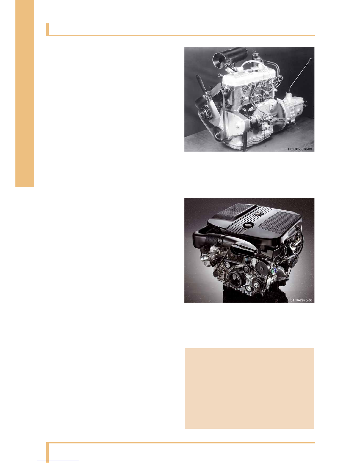
Engine 651
2.2 l displacement and 150 kW output. Installed in the
C-Class as of October 2008.
Engine 138
2.6 l displacement and 33 kW output. Installed in the
Mercedes-Benz 260 D, the world's first diesel passenger
car, in 1936.
i Note
A detailed description of the new CDI system can
be found in the System Description for engine 651.
Order number: 6516 1363 02
– This printout will not be recorded by the update service. Status: 09 / 2008 –
Overview
7
Introduction of New Generation of 4-Cylinder Inline Engines, OM 651
q
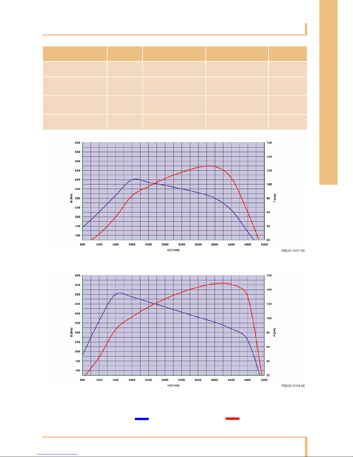
Engine data
Comparison Engine 646.821 EVO Engine 651.911 Difference
Displacement cm
3
2,148 2,143 –0.2%
Rated output kW
at rpm
125
3,800
150
4,200
+20%
Rated torque Nm
at rpm
400
2,000
500
1,600…1,800
+25%
Maximum rpm rpm 4,900 5,200 +6%
Engine 646.821 EVO
Engine 651.911
n Engine speed M Torque
POutput
– This printout will not be recorded by the update service. Status: 09 / 2008 –

8
Overview
Introduction of New Generation of 4-Cylinder Inline Engines, OM 651
q
Highlights
New features
Based on the use of the latest innovative technologies,
engine 651 sets a new standard in terms of output and
torque characteristics, economy, exhaust emission
levels and smooth running. The engine features a
number of new developments which cannot be found
in this combination in any other series-produced
passenger car diesel engine.
Technology
The most important technical features of the new
engine are:
• Dual stage turbocharging with fixed geometry
• Directly actuated piezo injectors
• Gear drive in combination with a chain drive on the
output side
• Intake air-cooled engine control unit
on air filter housing
• Main bearing bridge with integrated
Lanchester housing
• Two Lanchester balance shafts
• Drive gear friction welded to crankshaft
• Vibration dampers
(quadruple bolted)
• Universal timing case cover for adaptation to
va
rious transmission models
• Major assembly carrier with variable arrangement
as per vehicle
concept
• Two knock sensors
• Two-piece oil pan (noise optimized)
• Oil pan bottom section made of plastic
Thermal management
The new thermal management system consists of:
• Shutoff-capable coolant pump
• Cylinder head with two-piece water jacket
• Shutoff-capable oil spray nozzles combined with
pisto
n crown cooling
• Oil pump volume-controlled at clean oil side
i Note
Further information on repairing and maintaining
engine 651 can be found in the Workshop Information System (WIS).
i Note
Friction-welded connections involve connecting
two parts together by force. The application of friction and pressure produces a fixed connection
without the use of welding consumable.
– This printout will not be recorded by the update service. Status: 09 / 2008 –
Overview
9
Introduction of New Generation of 4-Cylinder Inline Engines, OM 651
q
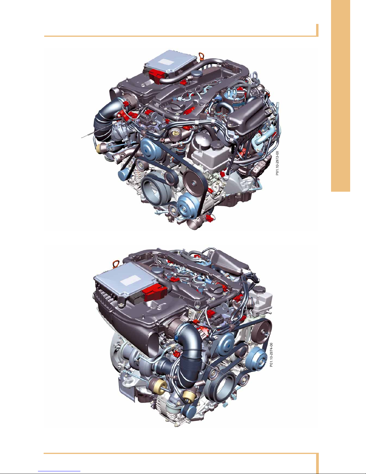
Engine views
Engine 651: Side view from right
Engine 651: Side view from left
– This printout will not be recorded by the update service. Status: 09 / 2008 –

10
Overview
Introduction of New Generation of 4-Cylinder Inline Engines, OM 651
q
System comparison
Comparison Engine 646.821EVO
C 220 CDI
Engine 651.911
C 250 CDI
Market launch 06 / 2006 10 / 2008
Combustion system Diesel direct injection
No. of cylinders 4
Engine configuration Inline
Bore mm 88.3 83.0
Stroke mm 88.3 99.0
Compression ratio e 16.5:1 16.2:1
Camshafts – drive Duplex chain Simplex chain
Camshafts – number 2 2
Valve actuation Cup tappet
with hydraulic valve
clearance compensation
Roller-type cam follower
with hydraulic valve
clearance compensation
Turbocharger type 1-stage turbocharging with
variable turbine geometry
2-stage turbocharging with
fixed geometry
Boost pressure control Electric Pneumatic
Measures for low-emission
combustion
Intake port shutoff,
exhaust gas recirculation
(EGR) with separate EGR
cooler
Intake port shutoff, EGR
cooling and EGR bypass
Fuel injector – type Solenoid injector Directly controlled piezo
injector
Fuel injector – diameter mm 17 19
Firing order 1-3-4-2
Oil pump – drive Simplex chain Gear drive
Alternator – current rating A 200 180
Engine weight DIN (dry) approx. kg 190 203
– This printout will not be recorded by the update service. Status: 09 / 2008 –

Overview
11
Introduction of New Generation of 4-Cylinder Inline Engines, OM 651
q
At a glance
Objective Measures on engine 651
Optimized comfort Stiffer crankcase with full-length crankshaft bearing bridge
Wide crankshaft main bearing; friction-optimized with center bearing
Two low-positioned Lanchester balance shafts for smooth engine running
Plastic cylinder head cover with integrated ventilation
Maintenance-free, long-life simplex chain as camshaft drive
Engine cover with adjusted acoustic damping
Improved fuel
economy
Optimized flow conditions (air ducting, intake ports)
Dual stage turbocharging
Optimized charge air cooling and exhaust gas recirculation cooling
Reduction in friction through gear drive and balance shafts mounted
on roller bearings
Compliance with
exhaust emissions
standards (Euro 5
standard)
Optimized shape of combustion chamber
7-hole injection nozzles
More precise injection times
Optimized air ducting
Exhaust gas recirculation (EGR) with EGR pre-cooler and EGR cooler, EGR valve and
switched EGR bypass
Electric intake air throttling
Shutoff-capable coolant pump and shutoff-capable oil spray nozzles
Exhaust system with oxidation catalytic converter and diesel particulate filter
– This printout will not be recorded by the update service. Status: 09 / 2008 –
Crankcase
12
Mechanical system
Introduction of New Generation of 4-Cylinder Inline Engines, OM 651
q
General
When engine 651 was developed, the design of the
crankcase was based on an overall concept with optimized spatial features. Accordingly, the gear drive
with
the oil pump drive and the Lanchester balance
shafts are positioned on the output side. The cast iron
crankcase is manufactured by sand casting.
The new design concept provides the following advantages:
•4 cm shorter crankcase compared to predecessor
version
• Improved pedestrian protection through
positioning of gear drive and
camshaft drive on
output side
• Universal timing case cover for adaptation to
various transmis
sion models
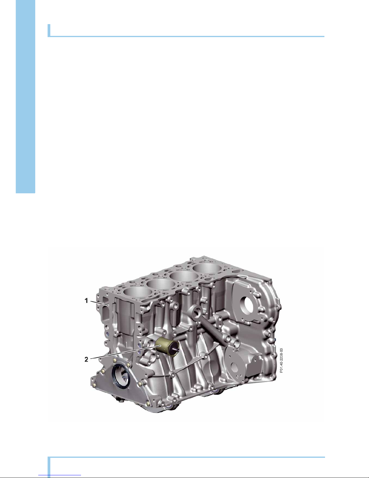
Crankcase
1 Crankcase 2 Oil spray nozzle shutoff valve
– This printout will not be recorded by the update service. Status: 09 / 2008 –
Mechanical system
13
Introduction of New Generation of 4-Cylinder Inline Engines, OM 651
q
Cylinder head
General
The cylinder head is made of high-strength aluminum.
It is equipped with two camshafts and four valves per
cylinder. The cylinder head cover is made of plastic
with integrated ventilation. The cylinder head is characterized by the following new features:
• Maximum ignition pressure of 200 bar (previously
160
bar)
• Tangential and spiral intake ports
• Bore for piezo injector of 19 mm diameter
The upper duct of the two-piece water jacket supplies
the cylinder
head with coolant. The advantages of the
two-piece water jacket include:
• Greater structural rigidity
• Better heat dissipation
• Improved thermal management
The improved thermal management system is particularly beneficial in those areas which are exposed to
very
high temperatures. The high ignition pressure of
200 bar is only made possible by targeted cooling of
the individual components. The increased pressure
potential and optimized injection quantity are responsible for the high engine torque of 500 Nm and the
en
gine output of 150 kW.
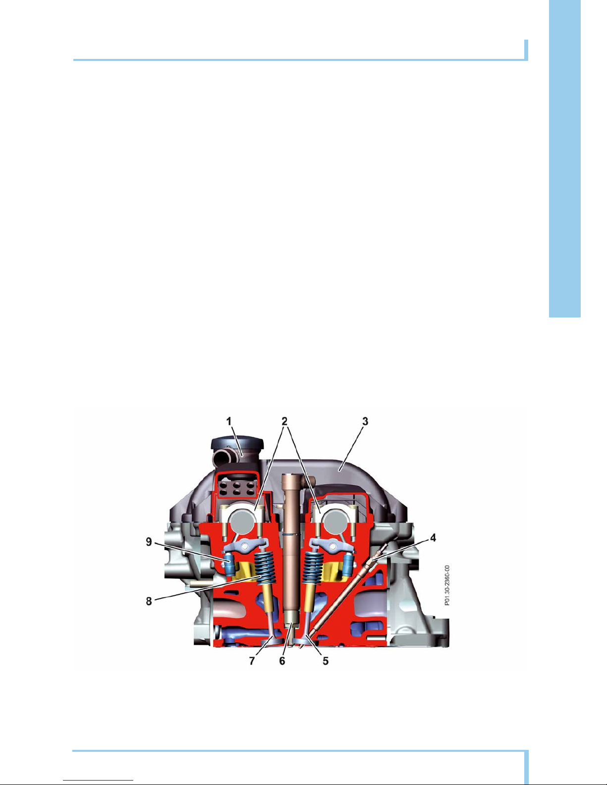
Cross-section of cylinder head
1 Ventilation
2 Main bearing bridge
3 Cylinder head cover
4Glow plug
5 Exhaust valve
6 Piezo injector
7 Intake valve
8 Valve spring
9 Valve clearance compensation
– This printout will not be recorded by the update service. Status: 09 / 2008 –
Oil pan
14
Mechanical system
Introduction of New Generation of 4-Cylinder Inline Engines, OM 651
q
Special design features
• Two-piece design
• Lower section of oil pan made of plastic
•Noise-optimized
• Service-optimized and cost-optimized replacement
parts
• Bolts secured to prevent them being lost
• Installation can be checked via special pins on seal
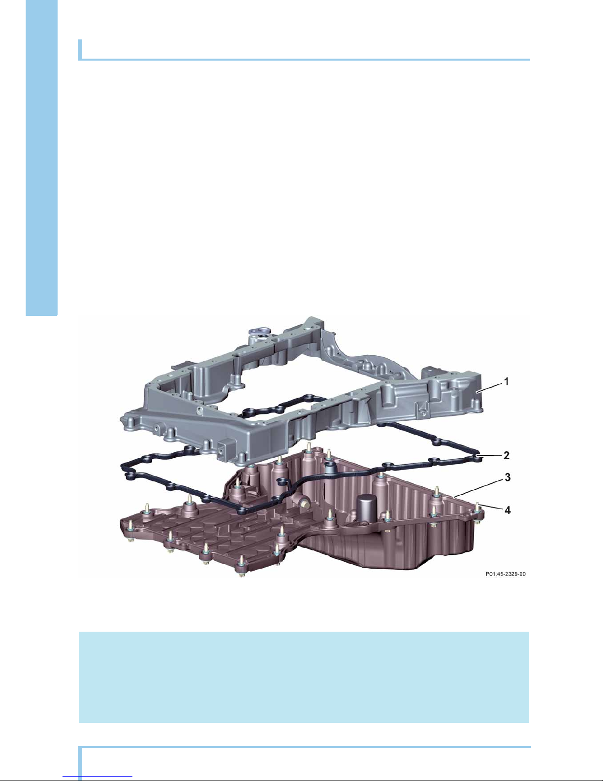
Oil pan
1 Upper section of oil pan
2Seal with pins
3 Lower section of oil pan (plastic)
4 Bolts with retainer (anti-loss)
i Note
Temporary level fluctuations are balanced out by the volume of the housing and the size of the drain bores
in the oil level check switch. This prevents unnecessary warning messages e.g. triggered by cornering.
– This printout will not be recorded by the update service. Status: 09 / 2008 –
Mechanical system
15
Introduction of New Generation of 4-Cylinder Inline Engines, OM 651
q
Crankshaft assembly
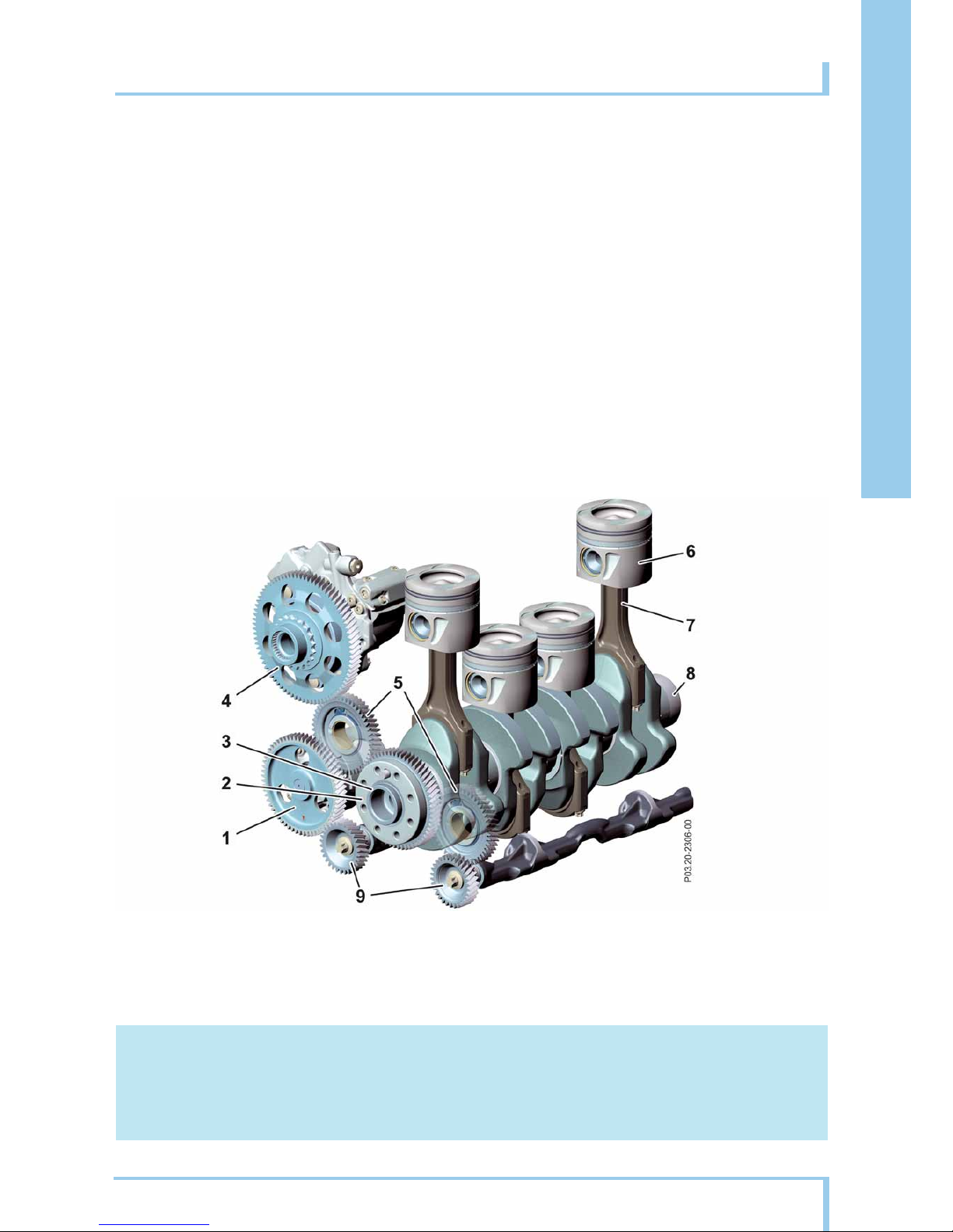
Crankshaft
The forged crankshaft with eight counterweights is
supported by five bearings for effective vibration
damping. The radiuses of the crank pins are rolled to
give them high strength. In addition, the connection
between the drive gear and crankshaft is friction
welded.
The vibration damper is fixed to the crankshaft with a
fourfold threaded connection.
Connecting rods
The weight-optimized connecting rods are made of
forged steel and are cracked at the level of the bearing
shells.
Balance shafts
Two Lanchester balance shafts are integrated in the
main bearing bridge and mounted on three roller bearings. They are driven in opposite directions by the gear
drive to counteract the inertia forces of the second
order which are generated. This ensures smooth
engine running.
i Note
The aluminum pistons run in friction-optimized cast-iron cylinder barrels. On this engine, they are all manufactured uniformly. There is therefore no differentiation between A, B or X sizes on this engine.
Crank assembly with gear drive
1 Oil and vacuum pump drive gear
2 Crankshaft gear
3Crankshaft
4 High-pressure pump drive gear
5 Intermediate gears
(tensioning gears)
6Piston
7 Connecting rod
8Vibration damper
9 Lanchester drive gears
– This printout will not be recorded by the update service. Status: 09 / 2008 –
Crankshaft assembly
16
Mechanical system
Introduction of New Generation of 4-Cylinder Inline Engines, OM 651
q
Camshafts
The gear drive drives the camshaft sprockets and the
connected camshafts via a timing chain. The maintenance free timing chain is tried and tested and has
proven longevity. The
cams are fixed to the camshaft
by means of internal high-pressure forming (IHU).
Camshaft sprocket
The camshaft sprocket is connected to the camshaft
by a center bolt. The center bolt of the camshaft has a
left-hand thread.
Sensor wheel
The sensor wheel is fixed to the exhaust camshaft. In
combination with the Hall sensor, the sensor wheel
makes it possible to determine the camshaft position
and rpm.
The Hall sensor generates a magnetic field through a
buil
t-in permanent magnet. The magnetic field is periodically interrupted by an orifice plate on the sensor
wheel while the engine is running. The
signal which
this generates is used by the CDI control unit and
serves as a substitute signal for emergency engine
operation if the position sensor for the crankshaft
fails.
Exhaust camshaft with sensor wheel
1 Drive gear 2 Exhaust camshaft 3 Sensor wheel with orifice plate
– This printout will not be recorded by the update service. Status: 09 / 2008 –
Mechanical system
17
Introduction of New Generation of 4-Cylinder Inline Engines, OM 651
q
Valve assembly
Valve assembly with hydraulic valve clearance compensation
The valve assembly was modified with the aim of optimizing friction and reducing the moved masses.
The camshafts control two intake valves and two
exhaust
valves per cylinder. This valve timing system
uses low-friction roller-type cam followers with
hydraulic valve clearance compensation.
Valve assembly
1 Slide rail
2 Timing chain
3 Camshaft drive gears
4Intake camshaft
5Exhaust camshaft
6 Sensor wheel with orifice plate
7 Roller-type cam followers
8 Hydraulic valve clearance compensator
9 Chain tensioner
10 Timing chain drive gear
– This printout will not be recorded by the update service. Status: 09 / 2008 –
 Loading...