


ML 320
ML 350
ML 500
ML 55 AMG

Our company and staff congratulate you
on the purchase of your new
Mercedes-Benz.
Your selection of our product is a demonstration of your trust in our company
name. Further, it exemplifies your desire to
own an automobile that will be as easy as
possible to operate and provide years of
service.
Your Mercedes-Benz represents the efforts of many skilled engineers and craftsmen. To help assure your driving pleasure,
and also the safety of you and your passengers, we ask you to make a small investment of time:
앫 Please read this manual carefully be-
fore putting it aside. Then return it to
your vehicle where it will be handy for
your reference.
앫 Please follow the recommendations
contained in this manual. They are designed to acquaint you with the operation of your Mercedes-Benz.
앫 Please pay attention to the warnings
and cautions contained in this manual.
They are designed to help improve the
safety of the vehicle operator and occupants.
We extend our best wishes for many miles
of safe, pleasurable driving.
Mercedes-Benz USA, LLC
A DaimlerChrysler Company

Introduction.......................................... 9
Product information ................................ 9
Operator’s Manual ............................... 10
Service and warranty information .. 10
Important notice for California
retail buyers and lessees of
Mercedes-Benz automobiles .......... 11
Maintenance .................................. 12
Roadside Assistance ...................... 12
Change of address or ownership.... 12
Operating your vehicle outside
the USA or Canada......................... 13
Where to find it .................................... 15
Symbols............................................... 16
Operating safety .................................. 17
Proper use of the vehicle ............... 17
Problems with your vehicle .................. 18
Reporting safety defects...................... 19
Reporting safety defects ................ 19
At a glance .......................................... 21
Cockpit................................................. 22
Instrument cluster ................................ 24
Center console ..................................... 27
Upper part ...................................... 27
Lower part ...................................... 28
Overhead control panel ........................ 29
Getting started................................... 31
Unlocking ............................................. 32
Remote control with folding key ..... 32
Adjusting .............................................. 34
Seats............................................... 34
Steering wheel ................................ 37
Mirrors ............................................ 38
Driving .................................................. 40
Fastening the seat belts.................. 40
Starting the engine ......................... 44
Switching on headlamps ................. 46
Turn signals..................................... 47
Windshield wipers ........................... 47
Rear window wiper.......................... 48
Problems while driving.................... 49
Contents
Parking and locking .............................. 50
Parking brake ................................. 50
Switching off headlamps................. 51
Turning off engine ........................... 51
Safety and Security ........................... 53
Occupant safety ................................... 54
Airbags ........................................... 55
Seat belts ....................................... 60
Children in the vehicle .................... 63
Blocking of rear door
window operation ........................... 69
Panic alarm .......................................... 70
Activating........................................ 70
Deactivating.................................... 70
Driving and safety systems .................. 71
ABS................................................. 71
BAS................................................. 73
4-ETS .............................................. 73
EBP ................................................. 74
ESP ................................................. 75
Anti-theft systems ................................ 78
Immobilizer ..................................... 78
Anti-theft alarm............................... 78

Contents
Tow-away alarm,
glass breakage sensor.................... 79
Controls in detail ............................... 83
Locking and unlocking ......................... 84
Remote control with folding key ..... 84
Opening the doors
from the inside ............................... 86
Opening the liftgate........................ 87
Closing the liftgate ......................... 88
Automatic central locking .............. 89
Locking and unlocking
from the inside ............................... 90
Seats.................................................... 91
Seat heater*................................... 91
Removing and installing
head restraints ............................... 92
Rear seats ...................................... 93
Third row seats*............................. 96
Memory function*................................ 99
Storing positions in memory ........ 100
Recalling positions from memory . 100
Exterior rear view mirror parking
position (passenger side) ............. 100
Lighting.............................................. 102
Combination switch ..................... 102
Fog lamps .................................... 105
Hazard warning flasher ................ 106
Interior lighting............................. 107
Instrument cluster ............................. 110
Instrument cluster illumination .... 110
Coolant temperature gauge ......... 111
Display in the speedometer ......... 111
Resetting trip odometer ............... 112
Tachometer .................................. 112
Outside temperature indicator ..... 112
Setting the clock .......................... 112
Automatic transmission ..................... 113
One-touch gearshifting ................. 113
Gear ranges.................................. 114
Gear selector lever position ......... 115
Accelerator position ..................... 117
Towing a trailer ............................ 117
Emergency operation (Limp Home
Mode)........................................... 117
Transmission control –
LOW RANGE mode............................. 118
Switching on LOW RANGE mode.. 118
Switching off LOW RANGE mode . 118
Good visibility .................................... 119
Rear view mirror .......................... 119
Headlamp cleaning system* ........ 121
Windshield wipers ........................ 122
Rear window wiper....................... 123
Sun visor ...................................... 123
Automatic climate control ................. 124
Automatic mode .......................... 126
Adjusting air volume and air
distribution manually ................... 127
Defrosting .................................... 128
Air recirculation mode.................. 128
Air conditioning............................ 129
Residual heat and ventilation ....... 130
Rear window defroster ................. 131
Rear passenger compartment
ventilation and rear automatic
climate control ............................. 131
Front and rear air outlets ............. 132
Power windows.................................. 134
Opening and closing the side
windows....................................... 134
Rear quarter windows* ................ 136
Sliding/pop-up roof* ......................... 137
Opening and closing the
sliding/pop-up roof...................... 137

Contents
Loading.............................................. 139
Loading instructions..................... 139
Partition net* ............................... 141
Cargo area cover blind* ............... 143
Cargo floor plates ........................ 144
Roof rack*.................................... 145
Driving systems ................................. 146
Cruise control .............................. 146
Parktronic system*
(Parking assist) ............................ 149
Useful features .................................. 152
Interior storage spaces ................ 152
Cup holders.................................. 154
Armrest in rear seat bench .......... 155
Ashtrays and cigarette lighter ...... 156
Electrical outlet ............................ 158
Telephone* .................................. 158
Tele Aid* ...................................... 159
Garage door opener ..................... 168
Trip computer*............................. 172
Operation ......................................... 177
The first 1000 miles (1500 km) ......... 178
Driving instructions............................ 179
Drive sensibly – save fuel ............. 179
Drinking and driving ...................... 179
Pedals ........................................... 179
Power assistance .......................... 179
Brakes........................................... 180
Driving off ..................................... 181
Parking.......................................... 182
Tires.............................................. 182
Hydroplaning................................. 183
Tire traction .................................. 183
Tire speed rating ........................... 184
Winter driving instructions ............ 184
Standing water.............................. 185
Off-road driving ............................. 186
Trailer towing ................................ 192
Passenger compartment............... 196
Driving abroad .............................. 197
Control and operation of radio
transmitters .................................. 197
Catalytic converter........................ 198
Emission control ........................... 198
Coolant temperature..................... 199
At the gas station ............................... 200
Check regularly and
before a long trip .......................... 201
Engine compartment .......................... 202
Hood............................................. 202
Engine oil ...................................... 203
Transmission fluid level ................ 206
Coolant ......................................... 206
Battery .......................................... 207
Windshield washer system and
headlamp cleaning system ........... 208
Tires and wheels ................................ 209
Important guidelines ..................... 209
Life of tire ..................................... 210
Direction of rotation ..................... 210
Checking tire inflation pressure .... 211
Rotating wheels ............................ 212
Winter driving ..................................... 213
Winter tires ................................... 213
Block heater (Canada only) ........... 214
Snow chains ................................. 214
Maintenance ...................................... 215
Clearing the service indicator ....... 215
Service term exceeded ................. 215
Calling up the service indicator .... 216
Resetting the service indicator ..... 216
Vehicle care ....................................... 217
Cleaning and care
of the vehicle ................................ 217

Contents
Practical hints.................................. 223
What to do if … .................................. 224
Lamps in instrument cluster ......... 224
Additional indicators in the
speedometer display .................... 235
Where will I find ...?............................ 236
First aid kit ................................... 236
Vehicle tool kit ............................. 237
Electric air pump (ML 55 AMG) .... 238
Spare wheel (space-saver tire) ..... 239
Unlocking/locking in an emergency.. 242
Unlocking the vehicle ................... 242
Locking the vehicle ...................... 243
Changing batteries ....................... 243
Fuel filler flap ............................... 244
Manually unlocking the
transmission selector lever .......... 245
Opening/closing in an emergency ..... 246
Sliding/pop-up roof*.................... 246
Replacing bulbs ................................. 247
Bulbs ............................................ 247
Replacing bulbs for front lamps.... 249
Replacing bulbs for rear lamps ..... 251
Adjusting headlamp aim ............... 253
Replacing wiper blades...................... 254
Removal ....................................... 254
Installation ................................... 254
Flat tire .............................................. 255
Mounting the spare wheel............ 255
Battery............................................... 261
Disconnecting the battery ............ 261
Removing the batteries ................ 262
Charging and reinstalling
batteries....................................... 262
Reconnecting the batteries .......... 262
Jump starting ..................................... 264
Towing the vehicle ............................. 267
Front towing eye .......................... 269
Rear towing eye ........................... 269
Stranded vehicle .......................... 270
Fuses ................................................. 271
Fuse box in engine
compartment ............................... 271
Auxiliary fuse box in front
passenger footwell ....................... 272
Technical data ................................. 273
Spare parts service............................ 274
Warranty coverage ............................ 275
Loss of Service and Warranty
Information Booklet ..................... 275
Identification labels ........................... 276
Layout of poly-V-belt drive................. 277
Engine ............................................... 278
Rims and tires ................................... 279
Rims and tires .............................. 279
Rims and winter tires* ................. 280
Spare wheel ................................. 280
Electrical system ............................... 281
Main Dimensions ............................... 282
Weights ............................................. 283
Fuels, coolants, lubricants etc. .......... 284
Capacities .................................... 284
Engine oils ................................... 286
Engine oil additives ...................... 286
Air conditioning refrigerant .......... 286
Brake fluid.................................... 286
Premium unleaded gasoline ......... 286
Fuel requirements ........................ 287
Gasoline additives ........................ 287
Coolants ...................................... 287

Anticorrosion/antifreeze.............. 288
Windshield and headlamp
washer system ............................. 290
Windshield and headlamp
washer fluid mixing ratio .............. 290
Consumer information ....................... 291
Uniform tire quality grading ......... 291
Temperature ................................ 292
Contents
Technical terms................................ 293
Index.................................................. 299

Contents

Product information
Please observe the following in your own
best interest:
We recommend using Mercedes-Benz original parts as well as conversion parts and
accessories explicitly approved by us for
your vehicle model.
We have tested these parts to determine
their reliability, safety and their special
suitability for Mercedes-Benz vehicles.
We are unable to make an assessment for
other products and therefore cannot be
held responsible for them, even if in individual cases an official approval or authorization by governmental or other agencies
should exist. Use of such parts and accessories could adversely affect the safety,
performance or reliability of your vehicle.
Please do not use them.
Introduction
Product information
Mercedes-Benz original parts as well as
conversion parts and accessories approved by us are available at your authorized Mercedes-Benz Light Truck Center
where you will receive comprehensive information, also on permissible technical
modifications, and where proper installation will be performed.
9

Introduction
Operator’s Manual
Operator’s Manual
This Operator’s Manual contains a great
deal of useful information. We urge you to
read it carefully and familiarize yourself
with the vehicle before driving.
For your own safety and longer service life
of the vehicle, we urge you to follow the instructions and warnings contained in this
manual. Ignoring them could result in damage to the vehicle or personal injury to you
or others. Vehicle damage caused by failure to follow instructions is not covered by
the Mercedes-Benz Limited Warranty.
Your vehicle may have some or all of the
equipment described in this manual.
Therefore, you may find explanations for
optional equipment not installed in your
vehicle. If you have any questions about
the operation of any equipment, your authorized Mercedes-Benz Light Truck Center will be glad to demonstrate the proper
procedures.
We continuously strive to improve our
product, and ask for your understanding
that we reserve the right to make changes
in design and equipment. Therefore, information, illustrations and descriptions in
this Operator’s Manual might differ from
your vehicle.
Optional equipment is also described in
this manual, including operating instructions wherever necessary. Since they are
special-order items, the descriptions and
illustrations herein may vary slightly from
the actual equipment of your vehicle.
If there are any equipment details that are
not shown or described in this Operator’s
Manual, your authorized Mercedes-Benz
Light Truck Center will be glad to inform
you of correct care and operating procedures.
The Operator’s Manual and Service Booklet are important documents and should be
kept with the vehicle.
Service and warranty information
The Service and Warranty Information
Booklet contains detailed information
about the warranties covering your
Mercedes-Benz, including:
앫 New Light Truck Limited Warranty,
앫 Emission System Warranty,
앫 Emission Performance Warranty,
앫 California, Maine, Massachusetts, and
Vermont Emission Control System
Warranty
(California, Maine, Massachusetts, and
Vermont only),
앫 State Warranty Enforcement Laws
(Lemon Laws).
10

Introduction
Operator’s Manual
Important notice for California retail
buyers and lessees of Mercedes-Benz
automobiles
Under California law you may be entitled to
a replacement of your vehicle or a refund
of the purchase price or lease price, if
Mercedes-Benz USA, LLC and/or its authorized repair or service facilities fail to fix
one or more substantial defects or malfunctions in the vehicle that are covered by
its express warranty after a reasonable
number of repair attempts. During the period of 18 months from original delivery of
the vehicle or the accumulation of
18 000 miles (approx. 29 000 km) on the
odometer of the vehicle, whichever occurs
first, a reasonable number of repair attempts is presumed for a retail buyer or
lessee if one or more of the following occurs:
(1) the same substantial defect or mal-
function results in a condition that is
likely to cause death or serious bodily
injury if the vehicle is driven, that defect or malfunction has been subject to
repair two or more times, and you have
directly notified Mercedes-Benz USA,
LLC in writing of the need for its repair,
(2) the same substantial defect or mal-
function of a less serious nature than
category (1) has been subject to repair
four or more times and you have directly notified us in writing of the need for
its repair, or
(3) the vehicle is out of service by reason
of repair of the same or different substantial defects or malfunctions for a
cumulative total of more than
30 calender days. Written notification
should be sent to us, not a dealer, at
Mercedes-Benz USA, LLC, Customer
Assistance Center, One Mercedes
Drive, Montvale, NJ 07645-0350.
11

Introduction
Operator’s Manual
Maintenance
The Service Booklet describes all the necessary maintenance work which should be
performed at regular intervals.
Always have the Service Booklet with you
when you take the vehicle to your authorized Mercedes-Benz Light Truck Center
for service. The service advisor will record
each service in the booklet for you.
Roadside Assistance
The Mercedes-Benz Roadside Assistance
Program provides factory-trained technical
help in the event of a breakdown. Calls to
the toll-free Roadside Assistance number
1-800-FOR-MERCedes (in the USA)
1-800-387-0100 (in Canada)
will be answered by Mercedes-Benz Customer Assistance Representatives
24 hours a day, 365 days a year.
Roadside Assistance will be provided in accordance with standard program guidelines which include providing service to the
vehicle up to a reasonable distance from a
paved roadway. We will make every effort
to assist in a breakdown situation, however, the accessibility of your vehicle will be
determined by our authorized Mercedes-Benz Light Truck Center technician
or the tow service provider on a
case-by-case basis and may be a factor in
our ability to respond.
Additional charges may be applicable for a
breakdown location determined not to be a
reasonably accessible roadside location as
determined by our authorized technician
and tow service provider.
For additional information refer to the
Mercedes-Benz Roadside Assistance Program brochure in your glove box.
Change of address or ownership
If you change your address, be sure to
send in the “Change of Address Notice”
found in the Service and Warranty Information Booklet, or simply call the
Mercedes-Benz Customer Assistance
Center (in the USA) at
1-800-FOR-MER-Cedes, or Customer Service (in Canada) at 1-800-387-0100. It is in
your own interest that we can contact you
should the need arise.
If you sell your Mercedes, please leave all
literature with the vehicle to make it available to the next operator.
If you bought this vehicle used, be sure to
send in the “Notice of Purchase of Used
Car” found in the Service and Warranty Information Booklet, or call the
Mercedes-Benz Customer Assistance Center (in the USA) at 1-800-FOR-MERCedes,
or Customer Service (in Canada) at
1-800-387-0100.
12

Operating your vehicle outside the USA
or Canada
If you plan to operate your vehicle in foreign countries, please be aware that:
앫 Service facilities or replacement parts
may not be readily available,
앫 unleaded gasoline for vehicles with cat-
alytic converters may not be available;
the use of leaded fuels will damage the
catalysts,
앫 gasoline may have a considerably low-
er octane rating, and improper fuel can
cause engine damage.
Introduction
Operator’s Manual
13

Introduction
Operator’s Manual
Warning! G
This Sport Utility Vehicle is designed for both on-road and off-road use. It can go places and perform tasks for which conventional 2-wheel drive
passenger cars were not intended. This vehicle will handle and maneuver differently from conventional passenger cars in driving conditions which
may occur on streets, highways and off-road use.
This vehicle has a higher ground clearance and a higher center of gravity than many passenger cars. As with other vehicles of this type, if you
make sharp turns at excessive speeds or abrupt maneuvers, the vehicle may roll over or may go out of control and crash. Utility vehicles have a
significantly higher rollover rate than other types of vehicles. Failure to operate this vehicle safely may result in an accident, rollover of the vehicle,
and severe or fatal injury.
Before you start to drive this vehicle, read the Operator’s Manual. Take time to become familiar with the driving characteristics of this vehicle. Be
sure you are familiar with all vehicle controls. Learn how your vehicle handles on different road surfaces. Do not attempt sharp turns at excessive
speeds or abrupt maneuvers or other unsafe driving actions that can cause loss of vehicle control. When driving off-road or working the vehicle
hard, do not overload it. And, always wear your seat belts at all times. In a rollover crash, an unbelted person is significantly more likely to die than
a person wearing a seat belt.
14

Where to find it
This Operator’s Manual is designed to provide comprehensive support information
for you, the vehicle operator. Each section
has its own reference color so you can find
information quickly.
At a glance
Here you will find an overview of all the
controls that can be operated from the
driver’s seat.
Getting started
Here you will find all the information you
need for your first drive. You should read
this section first if this is your first
Mercedes-Benz vehicle or if you are renting or borrowing this vehicle.
Safety and Security
Here you will find descriptions of the safety
features of your vehicle.
Controls in detail
Here you will find detailed information
about the equipment installed on your vehicle. This section expands on the “Getting
started” section and also describes technical innovations. If you are already familiar
with the basic functions of your vehicle,
this section will be of particular interest to
you.
Operation
Here you will find all the information you
need for the proper operation of your vehicle.
Practical hints
This section provides fast assistance for
dealing with problems you may encounter.
Introduction
Where to find it
Technical data
All important technical data for your vehicle can be found in this section.
Indexes
The glossary provides explanations of the
most important technical terms.
The table of contents and the index are designed to help you find information quickly
and easily.
The following publications are part of your
vehicle documentation:
앫 this Operator’s Manual
앫 the Service Booklet
Separate operating instructions will be
provided as required depending on the
equipment options installed in your vehicle.
15

Introduction
Symbols
Symbols
The following symbols are found in this
Operator’s Manual:
Warning! G
왘 This symbol points to instructions for
you to follow.
* Optional equipment is identified
with an asterisk. Since standard
equipment varies between models,
the descriptions and illustrations in
this manual may differ slightly from
the actual equipment of your vehicle.
Warning notices draw your attention to hazards that may endanger your health or life,
or the health or life of others.
!
Highlights hazards that may result in
damage to your vehicle.
i
Helpful hints or further information you
may find useful.
왘 A number of these symbols appearing
in succession indicates a multiple-step
procedure.
컄 Page This symbol tells you where to
look for further information on a
topic.
컄컄 This continuation symbol marks
an interrupted procedure which
will be continued on the next
page.
-> In the glossary of technical
terms, this symbol is used to
cross-reference term definitions.
Display
Words appearing in the multifunction display are printed in
the type shown here.
16

Operating safety
Warning! G
Work improperly carried out on electronic
components and associated software could
cause them to cease functioning. Because
the vehicle’s electronic components are interconnected, any modification made may
produce an undesired effect on other systems.
Electronic system malfunctions could seriously impair the operating safety of your vehicle.
Ensure that any repairs or modifications to
electronic components are carried out by an
authorized Mercedes-Benz Light Truck Center.
Other improper work or modifications on the
vehicle could also have a negative impact on
the operating safety of the vehicle.
Some safety systems only function while the
engine is running. You should therefore never turn off the engine while driving.
Introduction
Operating safety
Proper use of the vehicle
Proper use of the vehicle requires that you
are familiar with the following information
and rules:
앫 the safety precautions in this manual
앫 the “Technical data” section in this
manual
앫 traffic rules and regulations
앫 motor vehicle laws and safety stan-
dards
17

Introduction
Problems with your vehicle
Problems with your vehicle
If you should experience a problem with your vehicle, particularly one that you believe may affect its safe operation, we urge you to
immediately contact your authorized Mercedes-Benz Light Truck Center to have the problem diagnosed and corrected if required. If
the matter is not handled to your satisfaction, please discuss the problem with the Mercedes-Benz Light Truck Center management,
or if necessary contact us at one of the following addresses:
In the USA:
Customer Assistance Center
Mercedes-Benz USA, LLC
One Mercedes Drive
Montvale, NJ 07645-0350
In Canada:
Customer Relations Department
Mercedes-Benz Canada, Inc.
849 Eglinton Avenue East
Toronto, Ontario, M4G 2L5
18

Introduction
Reporting safety defects
Reporting safety defects
For the USA only:
The following text is published as required of manufacturers under Title 49, Code of U.S. Federal Regulations, Part 575 pursuant to the
“National Traffic and Motor Vehicle Safety Act of 1966”.
Reporting safety defects
If you believe that your vehicle has a defect which could cause a crash or could cause injury or death, you should immediately inform
the National Highway Traffic Safety Administration (NHTSA) in addition to notifying Mercedes-Benz USA, LLC.
If NHTSA receives similar complaints, it may open an investigation, and if it finds that a safety defect exists in a group of vehicles, it
may order a recall and remedy campaign. However, NHTSA cannot become involved in individual problems between you, your dealer,
or Mercedes-Benz USA, LLC.
To contact NHTSA, you may either call the Auto Safety Hotline toll-free at 1-888-327-4236 (or 366-0123 in Washington, D.C. area) or
write to: NHTSA, U.S. Department of Transportation, Washington, D.C. 20590. You can also obtain other information about motor vehicle safety from the Hotline.
19

20
At a glance
Cockpit
Instrument cluster
Center console
Overhead control panel
21
At a glance
Cockpit
Cockpit
22

At a glance
Cockpit
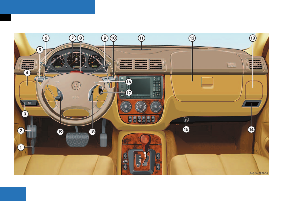
Item Page
1 Hood lock release 202
2 Parking brake pedal 50
3 Parking brake release 50
4 Left cup holder 154
5 Combination switch
앫 Turn signals
앫 High beam
6 Cruise control lever 146
7 Instrument cluster 110
8 Hazard warning flasher
switch
9 Lever for voice control
system*, see separate
operating instructions
46
106
Item Page
10 Windshield wiper/washer
switch
11 Front Parktronic* warning
indicator
12 Glove box 152
13 Right cup holder 154
14 Storage compartment
15 Electrical outlet 158
16 Horn
17 Headlamp washer button* 121
18 Steering lock with ignition 33
19 Steering wheel adjustment
stalk
122
150
37
23
At a glance
Instrument cluster
Instrument cluster
24

At a glance
Instrument cluster
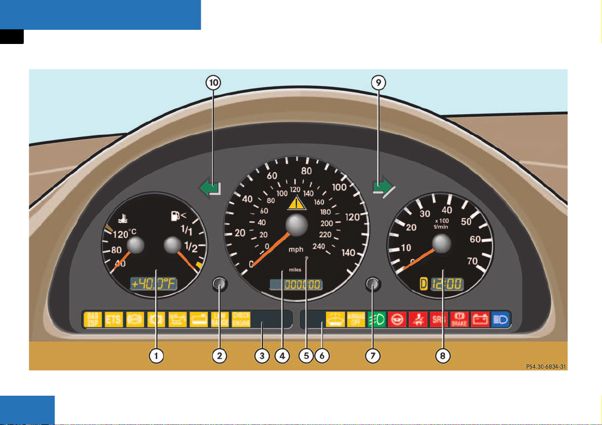
Item Page
1 Gauge for
Coolant temperature
Outside temperature
Fuel with fuel reserve warning lamp
2 Knob for
Activating instrument cluster
Adjusting intensity
of instrument lamps
Main odometer 111
Trip odometer readout/reset
Flexible Service
System (FSS)
111
112
233
110
110
112
215
Item Page
3 Left indicator lamps
with:
¿ Brake Assist Sys-
tem (BAS)/Electronic Stability
Program (ESP) malfunction warning
lamp
{ Electronic Traction
System (4-ETS) malfunction indicator
lamp
- Antilock Brake Sys-
tem (ABS) malfunction indicator lamp
2 Brake pad wear in-
dicator lamp
: Low engine oil level
warning lamp
225
226
225
234
229
Item Page
/ Low engine coolant
level warning lamp
ê Low range indicator
lamp
? Engine malfunction
indicator lamp
4 Speedometer with:
v 4-ETS (Electronic
Traction System)/Electronic
Stability Program
(ESP) warning lamp
Trip/main odometer
Flexible Service
System (FSS)
Engine oil level indicator
230
226
232
224
111
215
204
25

At a glance
Instrument cluster
Item Page
5 Photo sensor
(adjusts the brightness of
the digital displays located
in 1, 4 and 8)
6 Right indicator lamps
with:
W Low wind-
shield/headlamp
washer system fluid
level warning lamp
7 Front passenger air-
bag switched off
‡ Front fog lamp
switched on
234
232
105
Item Page
_ Steering wheel ad-
justment not locked
< Seat belt nonusage
warning lamp
1 Supplemental Re-
straint System
(SRS) indicator
É Brake warning lamp 228
# Charge indicator
lamp
A High beam head-
lamp switched on
229
234
227
229
233
47
Item Page
7 Knob for setting clock 112
8 Tachometer with:
Selector lever
position
Clock 112
9 K Turn signal
indicator lamp right
10 L Turn signal
indicator lamp left
114
26
Center console
Upper part
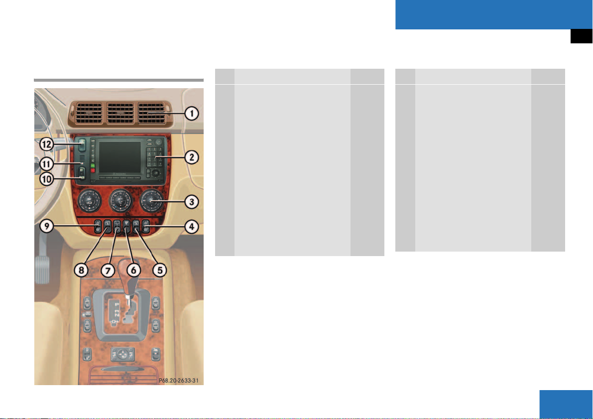
Item Page
1 Air outlets, automatic
climate control
2 MCS, see separate
operating instructions
3 Automatic climate control 124
Rear window defroster
switch
4 Seat heater switch*,
passenger side
5 Rear quarter window
switch*, right
6 ESP control switch 75
132
131
91
136
At a glance
Center console
Item Page
7 Rear window wiper/wash-
er switch
8 Rear quarter window
switch*, left
9 Seat heater switch*,
driver’s side
10 Front and rear fog lamp
switch
11 Indicator lamp for antitheft
alarm system
12 Transmission control
switch, LOW RANGE mode
123
136
91
105
78
118
27
At a glance
Center console
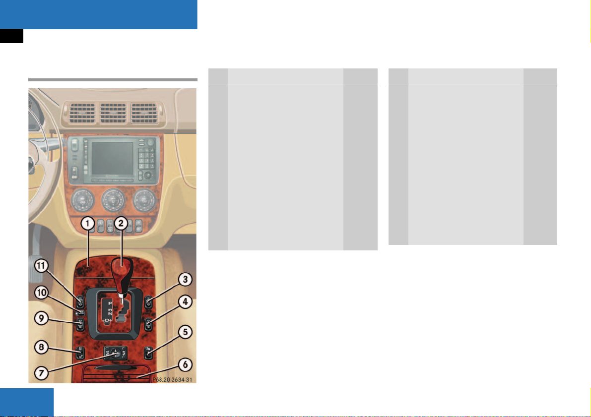
Lower part
Item Page
1 Ashtray with cigarette
lighter
2 Selector lever for
automatic transmission
3 Power window switch, right
front door
4 Power window switch, right
rear door
5 Parking assist* (Parktron-
ic) deactivation switch
6 Storage compartment with
cup holder
156
44
134
134
149
154
Item Page
7 Exterior rear view mirror
adjustment switch
Exterior rear view mirror
electrically folding*
8 Central locking switch 89
9 Power window switch, left
rear door
10 Switch for rear door win-
dow override
11 Power window switch, left
front door
38
120
134
69
134
28
Overhead control panel
At a glance
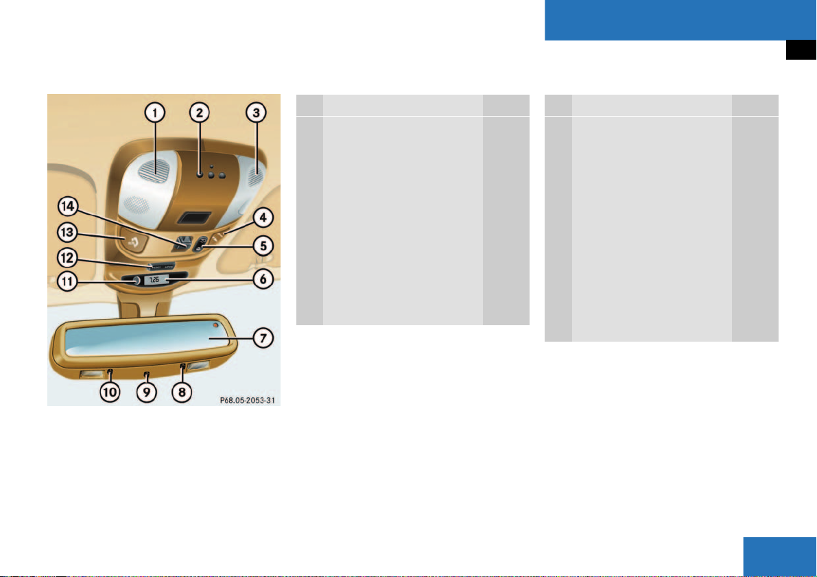
Overhead control panel
Item Page
1 Front left interior lighting 107
2 Signal transmitter keys for
garage door opener
3 Front right interior lighting 107
4 Roadside Assistance
button
Information button 165
5 Interior lighting control 107
6 Trip computer* display 172
7 Rear view mirror 119
168
163
Item Page
8 Right reading lamp on/off 108
9 Automatic antiglare func-
tion* on/off
10 Left reading lamp on/off 108
11 Glass breakage sensor 79
12 Trip computer* control 172
Tow-away alarm switch 80
13 Tele Aid (emergency call
system) button
14 Sliding/pop-up roof*
switch
119
163
137
29

30

Getting started
Unlocking
Adjusting
Driving
Parking and locking
31

Getting started
Unlocking
The “Getting started” section provides an
overview of the vehicle’s most basic functions. First-time Mercedes-Benz owners
should pay special attention to the information given here.
If you are already familiar with the basic
functions described here, the “Controls in
detail” section will help you with further information. The corresponding page references are at the end of each segment.
Unlocking
Remote control with folding key
Remote control with folding key
1 Â Panic button (컄 page 70)
2
ΠUnlock button
3
‹ Lock button
4 Release button for key
5
Š Unlock button for liftgate
왘 Press unlock button Œ on the re-
mote control.
The indicator lamps light up for a short
time. The locking knobs in the doors
move up.
왘 Press release button 4 on the remote
control.
The key folds out.
왘 Get in the vehicle and insert the key in
the steering lock (
컄 page 33).
More information can be found in the
“Controls in detail” section (
컄 page 84).
32

Getting started
Unlocking
Steering lock positions
Warning! G
When leaving the vehicle always remove the
key from the steering lock and lock the vehicle. Do not leave children unattended in the
vehicle, or with access to an unlocked vehicle. Unsupervised use of vehicle equipment
may cause an accident and/or serious personal injury.
Steering lock
0 For removing key
The steering is locked when the key is
removed from the steering lock. If necessary, move steering wheel slightly to
allow the locking mechanism to engage.
1 Unlocking steering. Power supplies to
some electrical consumers, such as
seat adjustment
2 Ignition (power supply for all electrical
consumers) and driving position (selector lever is unlocked)
3 Starting position
!
To prevent accelerated battery discharge and a possible dead battery, always remove the key from the steering
lock.
i
The key can only be withdrawn in
position 0.
If necessary, move steering wheel
slightly to allow the key to be turned
clockwise to position 1.
A warning sounds when the driver’s
door is opened and the key is in steering lock position 0 or 1.
More information can be found in the
“Controls in detail” section (
컄 page 84).
33

Getting started
Adjusting
Adjusting
Warning! G
All seat, head restraint, steering wheel, and
rear view mirror adjustments, as well as fastening of seat belts, must be done before
the vehicle is put into motion.
Seats
Depending on the vehicle’s equipment,
you can adjust the seats manually or electrically.
Warning! G
Do not adjust the driver’s seat while driving.
Adjusting the seat while driving could cause
the driver to lose control of the vehicle.
Never ride in a moving vehicle with the seat
back reclined. Sitting in an excessively reclined position can be dangerous. You could
slide under the seat belt in a collision. If you
slide under it, the belt would apply force at
the abdomen or neck.
That could cause serious or fatal injuries.
The seat back and seat belts provide the
best restraint when the wearer is in an upright position and belts are properly positioned on the body. Your seat must be
adjusted so that you can correctly fasten
your seat belt (
Never place hands under the seat or near
any moving parts while a seat is being adjusted.
컄 page 40).
Warning! G
When leaving the vehicle always remove the
key from the steering lock and lock your vehicle.
Do not leave children unattended in the vehicle or with access to an unlocked vehicle.
Unsupervised use of vehicle equipment may
cause an accident and/or serious personal
injury.
Warning! G
Children 12 years old and under must never
ride in the front seat, except in a
Mercedes-Benz authorized BabySmart
compatible child seat, which operates with
the BabySmart
hicle to deactivate the passenger side front
airbag when it is properly installed. Otherwise they will be struck by the airbag when
it inflates in a crash. If this happens, serious
or fatal injury will result.
According to accident statistics, children
are safer when properly restrained in the
rear seating positions than in the front seating positions. Infants and small children
must ride in back seats and be seated in an
appropriate infant or child restraint system,
which is properly secured with the vehicle's
seat belt and top tether strap, or secured via
lower anchors and top tether strap, fully in
accordance with the child seat manufacturer’s instructions.
TM
system installed in the ve-
TM
34

Getting started
Adjusting
A child’s risk of serious or fatal injuries is
significantly increased if the child restraints
are not properly secured in the vehicle and
the child is not properly secured in the child
restraint.
Adjusting manual seats
1 Seat height
2 Seat fore and aft adjustment
3 Backrest tilt
4 Head restraint height
Seat height
왘 Raise lever 1.
왘 The seat moves downward.
왘 Lean forward to raise the seat.
i
If necessary, hold onto the steering
wheel while adjusting the seat height in
order to take weight off the seat.
왘 Release lever 1.
Seat fore and aft adjustment
왘 Lift handle 2.
왘 Slide seat to desired position.
Adjust a comfortable seating position
that still allows you to reach the accelerator/brake pedal safely. The position
should be as far rearward as possible,
consistent with ability to properly operate controls.
왘 Release handle 2.
The seat must be properly engaged.
35

Getting started
Adjusting
Backrest tilt
왘 Turn handwheel 3 until your hands are
slightly angled when holding the steering wheel.
Head restraint height
Warning! G
For your protection, drive only with properly
positioned head restraints.
Adjust head restraint to support the back of
the head approximately at ear level.
Do not drive the vehicle without the seat
head restraints. Head restraints are intended to help reduce injuries during an accident.
왘 Pull up or push down on head restraint
until it is in desired position.
Head restraint tilt
왘 Manually adjust the angle of the head
restraint. Push or pull on the lower
edge of the head restraint cushion.
Adjusting power seats*
Warning! G
The power seats can also be operated with
the appropriate door open. Do not leave
children unattended in the vehicle, or with
access to an unlocked vehicle. Unsupervised use of vehicle equipment may cause
an accident and/or serious personal injury.
The seat adjustment switch is located on
the entry side of each front seat base.
왘 Switch on the ignition by turning the
key in the steering lock to position 2
(
컄 page 33).
All the lights in the instrument cluster
light up.
1 Seat height
2 Seat fore and aft adjustment
3 Seat cushion tilt
4 Backrest tilt
Seat height
왘 Press the switch up or down in the di-
rection of arrow 1.
36

Getting started
Adjusting
Seat fore and aft adjustment
왘 Press the switch forward or backward
in the direction of arrow 2 until you can
comfortably press the pedals all the
way to the floor.
Seat cushion tilt
왘 Press the switch up or down in the di-
rection of arrow 3 until your upper legs
are lightly supported.
Backrest tilt
왘 Press the switch forward or backward
in the direction of arrow 4 until your
hands are slightly angled when holding
the steering wheel.
i
With the front door open, the seats can
still be adjusted approx. 30 minutes after the ignition has been turned off.
Head restraint height
Warning! G
For your protection, drive only with properly
positioned head restraints.
Adjust head restraint to support the back of
the head approximately at ear level.
Do not drive the vehicle without the seat
head restraints. Head restraints are intended to help reduce injuries during an accident.
왘 Pull up or push down on head restraint
until it is in desired position.
Head restraint tilt
왘 Manually adjust the angle of the head
restraint. Push or pull on the lower
edge of the head restraint cushion.
More information can be found in the
“Controls in detail” section (
컄 page 91).
Steering wheel
Warning! G
Do not adjust the steering wheel while driving. The steering wheel must be locked
while driving. Adjusting the steering wheel
while driving, or driving without the steering
column locked could cause the driver to lose
control of the vehicle.
1 Lever
37

Getting started
Adjusting
왘 Move lever 1 to its stop down.
왘 Move steering wheel up or down to de-
sired position.
왘 Move lever 1 to its stop up.
The steering column is locked.
!
If the indicator lamp _ (컄 page 26)
comes on while the engine is running,
the steering column is not locked properly.
Mirrors
Adjust the inside and exterior rear view
mirrors before driving so that you have a
good view of the road and traffic conditions.
Warning! G
In the case of an accident, liquid electrolyte
may escape the mirror housing if the mirror
glass breaks.
Electrolyte has an irritating effect. Do not allow the liquid to come into contact with
eyes, skin, clothing, or the respiratory system. In case it does, immediately flush affected area with water, and seek medical
help if necessary.
Inside rear view mirror
왘 Manually adjust the inside rear view
mirror.
Exterior rear view mirrors
Warning! G
Exercise care when using the passenger
side exterior rear view mirror. The mirror
surface is convex (outwardly curved surface
for a wider field of view). Objects in mirror
are closer than they appear. Check your inside rear view mirror or glance over your
shoulder before changing lanes.
!
Electrolyte drops coming into contact
with the vehicle paint finish can only be
completely removed while in their liq-
uid state and by applying plenty of wa-
ter.
38

Getting started
Adjusting
The buttons are on the lower part of the
center console.
1 Driver’s side mirror
2 Passenger side mirror
3 Adjustment button
왘 Switch on the ignition by turning the
key in the steering lock to position 2
(
컄 page 33)
All the lights in the instrument cluster
light up.
왘 Press button 1 for the left mirror or
button 2 for the right mirror.
왘 Push adjustment button 3 up, down,
left or right according to the setting desired.
i
With the front doors closed, the exterior mirrors can still be adjusted approx.
30 minutes after the ignition has been
turned off.
At low outside temperatures, the exterior mirrors will be automatically
heated.
More information can be found in the
“Controls in detail” section (
컄 page 119).
39

Getting started
Driving
Driving
Warning! G
Do not lay any objects in the driver’s footwell. Be careful that floor mats or carpets in
the driver’s footwell have sufficient clearance for the pedals.
During sudden driving or braking maneuvers
the objects could get caught between the
pedals. You could then no longer brake or
accelerate.
Fastening the seat belts
Warning! G
Always fasten your seat belt before driving
off. Always make sure your passengers are
properly restrained, even those sitting in the
rear and pregnant women.
Failure to wear and properly fasten and position your seat belt greatly increases your
risk of injuries and their likely severity in an
accident. You and your passengers should
always wear seat belts.
If you are ever in an accident, your injuries
can be considerably more severe without
your seat belt properly buckled. Without
your seat belt buckled, you are much more
likely to hit the interior of the vehicle or be
ejected from it. You can be seriously injured
or killed.
In the same crash, the possibility of injury or
death is lessened if you are wearing your
seat belt. The airbags can only protect as expected if the occupants are using their seat
belts (
컄 page 54).
Warning! G
Children 12 years old and under must never
ride in the front seat, except in a
Mercedes-Benz authorized BabySmart
compatible child seat, which operates with
the BabySmart
hicle to deactivate the passenger front airbag when it is properly installed. Otherwise
they will be struck by the airbag when it inflates in a crash. If this happens, serious or
fatal injury will result.
According to accident statistics, children
are safer when properly restrained in the
rear seating positions than in the front seating positions. Infants and small children
must ride in back seats and be seated in an
appropriate infant or child restraint system,
which is properly secured with the vehicle's
seat belt and top tether strap, or secured via
lower anchors and top tether strap, fully in
accordance with the child seat manufacturer's instructions.
TM
system installed in the ve-
TM
40

Getting started
Driving
A child’s risk of serious or fatal injuries is
significantly increased if the child restraints
are not properly secured in the vehicle and
the child is not properly secured in the child
restraint.
Warning! G
Never ride in a moving vehicle with the backrest reclined. Sitting in an excessively reclined position can be dangerous. You could
slide under the seat belt in a collision. If you
slide under it, the belt would apply force at
the abdomen or neck. That could cause serious or even fatal injuries. The backrest and
seat belt provide the best restraint when the
wearer is in an upright position and the belt
is properly positioned on the body.
Warning! G
Never let more people ride in the vehicle
than there are seat belts available. Be sure
everyone riding in the vehicle is correctly restrained with a separate seat belt.
Warning! G
Read and observe the additional warning notices printed in the “Safety and Security”
section (
컄 page 57) and (컄 page 60).
1 Latch plate
2 Buckle
3 Release button
4 Seat belt housing
41

Getting started
Driving
왘 With a smooth motion, pull the belt
from seat belt housing 4.
왘 Place the belt over your shoulder.
왘 Push latch plate 1 into buckle 2 until it
clicks.
왘 If necessary, tighten the lap portion to
a snug fit by pulling shoulder portion
up.
왘 If ne cessary, adjust the seat belt to the
correct height (
컄 page 43).
Proper use of seat belts:
앫 Do not twist the belt when fastening.
앫 Adjust the seat belt so that the shoul-
der portion is located as close as possible to the middle of the shoulder (it
should not touch the neck or pass under the arm).
앫 Position the lap belt as low as possible
on your hips (over hip joint) and not
across the abdomen.
앫 Place the seat backrest in a nearly up-
right position.
앫 Each seat belt should never be used for
more than one person at a time.
앫 Do not fasten a seat belt around a per-
son and another object at the same
time.
앫 Check your seat belt during travel to
ensure that it is properly positioned.
앫 Ensure that the seat belt is always fit-
ted snugly. You should avoid wearing
bulky clothing, such as winter coats,
when traveling in the vehicle.
Warning! G
Do not pass belts over sharp edges. They
could tear.
Do not allow the belt to get caught in the
door or in the seat adjustment mechanism.
This could damage the belt.
Never attempt to make modifications to
seat belts. This could impair the effectiveness of the belts.
Damaged seat belts or belts that were highly
stressed in an accident must be replaced by
an authorized Mercedes-Benz Light Truck
Center.
42

Getting started
Driving
Seat belt height adjustment
Seat belt height can be adjusted for the following seats:
앫 Driver’s seat
앫 Passenger seat
앫 Outer rear seats
Adjust seat belt so that the shoulder portion is located as close as possible to the
middle of the shoulder (it should not touch
the neck or pass under the arm).
1 Release button
Adjusting seat belt higher
왘 Slide belt outlet upward.
The belt outlet engages in various positions.
Adjusting seat belt lower
왘 Press and hold release button 1.
왘 Slide belt outlet in desired position and
let go of release button 1.
43

Getting started
Driving
Starting the engine
Warning! G
Inhalation of exhaust gas is hazardous to
your health. All exhaust gas contains carbon
monoxide, and inhaling it can cause unconsciousness and lead to death.
Do not run the engine in confined areas
(such as a garage) which are not properly
ventilated. If you think that exhaust gas
fumes are entering the vehicle while driving,
have the cause determined and corrected
immediately. If you must drive under these
conditions, drive only with at least one window fully open.
Gearshift pattern for automatic
transmission
P Park position with selector lever lock
R Reverse gear
N Neutral
D Drive position
For more information on “Automatic transmission” (
컄 page 113).
왘 Make sure that the gear selector lever
is set to P.
!
Do not depress the accelerator.
왘 Turn the key in the steering lock to
position 3 and hold until the engine
starts (
컄 page 33).
왘 Depress the brake pedal.
The selector lever lock is released.
For information on turning off the engine
with the key, see “Turning off engine”
(
컄 page 51).
44

Getting started
Driving
Starting difficulties
!
Ensure that the brake pedal is depressed when starting the engine.
If the engine does not start as described,
carry out the following steps:
왘 Turn key in starter to position 0 and re-
peat starting procedure.
Remember that extended starting attempts can drain the battery.
왘 Get a jump start (컄 page 264).
If the engine does not start after several
starting attempts, there could be a malfunction in the engine electronics or in the
fuel supply system.
왘 Notify an authorized Mercedes-Benz
Light Truck Center.
Parking brake
Warning! G
When leaving the vehicle always remove the
key from the steering lock and lock the vehicle. Do not leave children unattended in the
vehicle, or with access to an unlocked vehicle. Children could release the parking
brake, which could result in an accident
and/or serious personal injury.
1 Parking brake pedal
2 Release handle
왘 Release the parking brake by pulling on
handle 2.
The indicator lamp
É in the instru-
ment cluster goes out.
Driving
왘 Place the gear selector lever in
position D or R.
i
Wait for the gear selection process to
complete before setting the vehicle in
motion.
왘 Release the brake pedal.
왘 Carefully depress the accelerator
pedal.
45

Getting started
Driving
!
If you hear a warning signal when driving off, you have forgotten to release
the parking brake.
Release the parking brake.
After a cold start the transmission engages
at a higher revolution. This allows the catalytic converter to reach its operating temperature earlier.
Warning! G
It is dangerous to shift the selector lever out
of P or N if the engine speed is higher than
idle speed. If your foot is not firmly on the
brake pedal, the vehicle could accelerate
quickly forward or in reverse. You could lose
control of the vehicle and hit someone or
something. Only shift into gear when the engine is idling normally and when your right
foot is firmly on the brake pedal.
Warning! G
On slippery road surfaces, never downshift
in order to obtain braking action. This could
result in drive wheel slip and reduced vehi-
cle control. Your vehicle’s ABS will not pre-
vent this type of loss of control.
More information can be found in the “Operation” section (
컄 page 177).
For information on off-road driving, see
Driving instructions (
컄 page 186).
Switching on headlamps
The combination switch is on the left of the
steering column.
Combination switch
1 Off
2 Low beam headlamps on
3 High beam lamps on
왘 Turn the switch to õ.
Low beam headlamps on.
46

Getting started
Driving
High beam
왘 Push the exterior lamp switch forward.
The high beam symbol
A in the
instrument cluster lights up.
More information can be found in the
“Controls in detail” section (
컄 page 102)
Turn signals
The combination switch is on the left of the
steering column.
Combination switch
1 Turn signals, right
2 Turn signals, left
왘 Press the combination switch up 1 or
down 2.
The switch is automatically cancelled
when the steering wheel is turned to a
large enough degree.
i
To signal minor directional changes,
move combination switch to point of
resistance only and release. The turn
signal blinks three times.
Windshield wipers
The combination switch is on the right of
the steering column.
Wiper switch
0 Windshield wipers off
1 Intermittent wiping
2 Normal wiper speed
3 Fast wiper speed
4 Wiping with windshield wiper fluid
47

Getting started
Driving
Switching on windshield wipers
왘 Make sure that the ignition is switched
on.
왘 Turn the wiper switch to the desired po-
sition 1, 2 or 3, depending on the inten-
sity of the rain.
Single wipe
왘 Press switch briefly in the direction of
arrow 2.
The windshield wipers wipe one time
without washer fluid.
Wiping with windshield washer fluid
왘 Pull and hold wiper switch in direction
of arrow 4.
The windshield wiper operates with
washer fluid.
More information on windshield wipers can
be found in the “Controls in detail” section
(
컄 page 122).
Rear window wiper
The button is on the upper part on the center console.
1 Intermittent wiping
2 Indicator lamp
3 Wiping with washer fluid
Switching on intermittent wiping
Make sure that the ignition is switched on.
왘 Press upper half 1 of the button.
Switching off intermittent wiping
왘 Press upper half 1 of the button again.
Wiping with washer fluid
왘 Press and hold lower half 3 of the but-
ton.
After releasing the button the wiper operates for additional five seconds.
48

Getting started
Driving
Problems while driving
The engine runs erratically and misfires
앫 An ignition cable may be damaged.
앫 The engine electronics may not be op-
erating properly.
앫 Unburned gasoline may have entered
the catalytic converter and damaged it.
왘 Give very little gas.
왘 Have the problem repaired by an au-
thorized Mercedes-Benz Center as
soon as possible.
The coolant temperature is over 248°F
(120°C)
The coolant is too hot and is no longer
cooling the engine.
왘 Stop the vehicle as soon as possible
and turn off the engine. Allow engine
and coolant to cool.
왘 Check the coolant level and add cool-
ant if necessary (
컄 page 206).
In case of accident
If the vehicle is leaking gasoline:
왘 Do not start the engine under any cir-
cumstances.
왘 Notify local fire and/or police authori-
ties.
If the extent of the damage cannot be determined:
왘 Notify an authorized Mercedes-Benz
Center.
If no damage can be determined on the
앫 major assemblies
앫 fuel system
앫 engine mount:
왘 Start the engine in the usual manner.
49

Getting started
Parking and locking
Parking and locking
You have now completed your first drive.
You have properly stopped and parked
your vehicle. End your drive as follows.
Warning! G
Wait until the vehicle is stationary before removing the key from the steering lock. The
vehicle cannot be steered when the key is
removed.
Warning! G
With the engine not running, there is no
power assistance for the steering system. In
this case, it is important to keep in mind that
a considerably higher degree of effort is necessary to steer the vehicle.
Warning! G
Do not park this vehicle in areas where com-
bustible materials such as grass, hay or
leaves can come into contact with the hot
exhaust system, as these materials could be
ignited and cause a vehicle fire.
To reduce the risk of personal injury as a re-
sult of vehicle movement, before turning off
the engine and leaving the vehicle always:
앫 Keep right foot on brake pedal.
앫 Firmly depress parking brake pedal.
앫 Move the selector lever to position P.
앫 Slowly release brake pedal.
앫 When parked on an incline, turn front
wheel towards the road curb.
앫 Turn the key to starter switch position 0
and remove.
앫 Take the key and lock vehicle when leav-
ing.
Parking brake
1 Parking brake
2 Release handle
왘 Step firmly on parking brake 1.
When the engine is running, the indicator lamp
É in the instrument cluster
will be illuminated.
50

Warning! G
When leaving the vehicle always remove the
key from the steering lock and lock the vehicle. Do not leave children unattended in the
vehicle, or with access to an unlocked vehicle. Children could release the parking
brake and/or move the gear selector lever
from position P, either of which could result
in an accident and/or serious personal
injury.
Warning! G
Getting out of your vehicle with the selector
lever not fully engaged in position P is dangerous. Also, when parked on an incline,
position P alone may not prevent your vehicle from moving, possibly hitting people or
objects.
Always set the parking brake in addition to
shifting to position P (
When parked on an incline, also turn front
wheel towards the road curb.
컄 page 50).
Switching off headlamps
왘 Turn the combination switch to 1
(
컄 page 46).
More information can be found in the
“Controls in detail” section (
컄 page 102).
Getting started
Parking and locking
Turning off engine
왘 Place the gear selector lever in P.
왘 Turn the key in the steering lock
(
컄 page 33) to position 0 and remove
it.
The immobilizer is activated.
i
Always set the parking brake in addition to shifting to position P.
!
To prevent accelerated battery discharge and a possible dead battery, always remove the key from the steering
lock.
51

Getting started
Parking and locking
i
The key can only be removed from the
steering lock with the gear selector lever in position P.
With the key removed and the driver’s
door open, a warning sounds if the vehicles exterior lamps are not switched
off.
왘 Press the seat belt release button
(
컄 page 40).
왘 Move the steering wheel slightly to al-
low the locking mechanism to engage.
왘 After exiting the vehicle press the lock
button
‹ on the remote control
(
컄 page 32).
The turn signals lamps blink three
times and the locking knobs on the
doors move down.
Warning! G
To prevent possible personal injury, always
keep hands and fingers away from the door
openings when closing the doors. Be espe-
cially careful when small children are
around.
Before closing doors, ensure that there is no
possibility of someone getting caught in a
door during closing.
More information on parking and locking
can be found in the “Controls in detail”
section (
컄 page 84).
52

Safety and Security
Occupant safety
Panic alarm
Driving and safety systems
Anti-theft systems
53

Safety and Security
Occupant safety
Occupant safety
In this section you will learn the most important facts about the restraint systems
of the vehicle.
The restraint systems are
앫 Seat belts
앫 Emergency tensioning device
앫 Airbags
앫 Child seats
앫 Child seat recognition
앫 Lower anchors and tethers for children
(LATCH)
As independent systems their protective
effects work in conjunction with each other.
i
For information on infants and children
traveling with you in the vehicle and restraint systems for infants and children, see “Children in the vehicle”
(
컄 page 63).
The warning lamp
cluster (
컄 page 26) lights up for about
1 in the instrument
4 seconds when the key is turned to
position 2. It goes out when you start the
engine. This shows that the restraint systems are operational.
If the lamp does not come on at all or if it
fails to extinguish after approximately
4 seconds or if it comes on thereafter, a
malfunction in the system has been detected.
More information can be found in the
“Practical hints” section (
컄 page 227).
Warning! G
In the event that the SRS malfunction indicator lamp lights up during driving or does not
come at all, the SRS may not be operational.
For your safety, we strongly recommend
that you visit an authorized Mercedes-Benz
Light Truck Center immediately to have the
system checked; otherwise the SRS may not
be activated when needed in an accident,
which could result in serious or fatal injury,
or it might deploy unexpectedly and unnecessarily which could also result in injury.
Improper work on the restraint systems can
lead to unintentional deployment or operational failure.
All work on these systems should therefore
only be carried out by an authorized
Mercedes-Benz Light Truck Center.
54

Safety and Security
Occupant safety
Airbags
Warning! G
Airbags are designed to reduce the potential
of injury in certain frontal (front airbags) impacts, or side (side impact and head protection window curtain airbags) impacts which
may cause significant injuries. However, no
system available today can totally eliminate
injuries and fatalities.
The activation of the SRS temporarily releases a small amount of dust from the airbags.
This dust, however, is neither injurious to
your health, nor does it indicate a fire in the
vehicle. The dust might cause some temporary breathing difficulty for people with asthma or other breathing trouble. To avoid this,
you may wish to get out of the vehicle as
soon as it is safe to do so. If you have any
breathing difficulty but cannot get out of the
vehicle after the airbag inflates, then get
fresh air by opening a window or door.
Warning! G
To reduce the risk of injury when the front
airbags inflate, it is very important for the
driver and passenger to always be in a properly seated position and to wear your seat
belt.
For maximum protection in the event of a
collision always be in normal seated position
with your back against the backrest. Fasten
your seat belt and ensure that it is properly
positioned on your body (
Since the airbag inflates with considerable
speed and force, a proper seating and hands
on steering wheel position will help to keep
you at a safe distance from the airbag. Occupants who are unbelted, out of position or
too close to the airbag can be seriously injured by an airbag as it inflates with great
force in the blink of an eye:
앫 Sit properly belted in an upright position
with your back against the backrest.
컄 page 40).
앫 Adjust the driver seat as far as possible
rearward, still permitting proper operation of vehicle controls. The distance
from the center of the driver’s breastbone to the center of the airbag cover on
the steering wheel must be at least ten
inches (25 cm) or more. You should be
able to accomplish this by a combination of adjustments to the seat and
steering wheel. If you have any problems, please see your authorized
Mercedes-Benz Light Truck Center.
앫 Do not lean with your head or chest
close to the steering wheel or dashboard.
앫 Keep hands on the outside of steering
wheel rim. Placing hands and arms inside the rim can increase the risk and
potential severity of hand/arm injury
when driver front airbag inflates.
앫 Adjust the passenger seat as far as pos-
sible rearward from the dashboard when
the seat is occupied.
컄컄
55

Safety and Security
Occupant safety
앫 Occupants, especially children, should
never lean their heads in the area of the
door where the side impact airbag inflates. This could result in serious injuries or death should the airbag be
triggered. Always sit upright, properly
use the seat belts and appropriate size
infant or child restraint system.
앫 Children 12 years old and under must
never ride in the front seat, except in a
Mercedes-Benz authorized
BabySmart
which operates with the BabySmart
TM
compatible child seat,
TM
system installed in the vehicle to deactivate the passenger side front airbag
when it is properly installed. Otherwise
they will be struck by the airbag when it
inflates in a crash. If this happens, serious or fatal injury will result.
Failure to follow these instructions can result in severe injuries to you or other occupants.
If you sell your vehicle you are responsible
to make the buyer aware of these points. Be
sure to give the buyer this Operator’s
Manual.
Warning G
Accident research shows that the safest
place for children in an automobile is in the
rear seat. Should you choose to place a child
12 years old or under in the passenger seat
of your vehicle, you must properly use a
BabySmart
off the passenger side front airbag
(
컄 page 65). BabySmart
er, turn off any side impact airbag.
It should be noted that with respect to both
front and rear side impact airbags there is a
possibility for a side airbag related injury if
occupants, especially children, are not prop-
erly seated or restrained when next to a side
airbag which needs to deploy rapidly in a
side impact in order to do its job.
TM
child restraint which will turn
TM
will not, howev-
To help avoid the possibility of injury, please
follow these guidelines: (1) occupants, especially children, should never place their bodies or lean their heads in the area of the door
where the side airbag inflates. This could result in serious injuries or death should the
side airbag be activated; (2) always sit upright, properly use the seat belts and use an
appropriately sized infant or child restraint
system for all children 12 years old or under;
and (3) always wear seat belts properly.
If you believe that, even with the use of
these guidelines, it would be safer for your
rear seat occupants to have both rear door
mounted side airbags deactivated, then deactivation can be accomplished upon your
written election to do so at your authorized
Mercedes-Benz Light Truck Center at an additional cost. Please contact your local authorized Mercedes-Benz Light Truck Center
or call our Customer Assistance Center at
1-800-FOR-MERCedes (1-800-367-6372)
for details.
56

Safety and Security
Occupant safety
i
Airbags are designed to activate only in
certain frontal (front airbags) impacts,
or side (side impact and head protection window curtain airbags) impacts
which exceed preset thresholds.
Only during these types of impacts, if of
sufficient severity to meet the deployment thresholds, will they provide their
supplemental protection.
The driver and passenger should always wear their seat belts. Otherwise it
is not possible for the airbags to provide their supplemental protection.
In cases of other frontal impacts, angled impacts, roll-overs, other side impacts, rear collisions, or other
accidents, the airbags will not be activated. The driver and passengers will
then be protected by the fastened seat
belts.
We caution you not to rely on the presence of the airbags in order to avoid
wearing your seat belt.
Your vehicle was originally equipped
with airbags that are designed to activate in certain impacts exceeding a preset threshold to reduce the potential
and severity of injury. It is important to
your safety and that of your passenger
that you replace deployed airbags and
repair any malfunctioning airbags to ensure that the vehicle will continue to
provide supplemental crash protection
for occupants.
Safety guidelines for the seat belt,
emergency tensioning device and
airbag
Warning G
앫 Damaged seat belts or belts that were
highly stressed in an accident must be
replaced and their anchoring points
must also be checked. Use only belts installed or supplied by an authorized
Mercedes-Benz Light Truck Center.
앫 No modifications of any kind may be
made to any components or wiring of
the SRS. This includes changing or removing any component or part of the
SRS, the installation of additional trim
material, badges, etc. over the steering
wheel hub, passenger front airbag cover, or door trim panels, and installation
of additional electrical/electronic
equipment on or near SRS components
and wiring. Keep area between airbags
and occupants free from objects (e.g.
packages, purses, umbrellas, etc.).
57

Safety and Security
Occupant safety
앫 Airbags and ETDs are designed to func-
tion on a one-time-only basis. An airbag
or emergency tensioning device (ETD)
that was activated must be replaced.
앫 Do not pass belts over sharp edges.
They could tear.
앫 Do not make any modification that could
change the effectiveness of the belts.
앫 Do no t hang items such a s coat han gers
from the coat hooks or handles over the
door. These items may turn into projectiles and cause head and other injuries
when curtain airbag is deployed.
앫 An airbag system component within the
steering wheel gets hot after the airbag
has inflated. Do not touch.
앫 Improper work on the system, including
incorrect installation and removal, can
lead to possible injury through an unintended activation of the SRS.
앫 In addition, through improper work
there is a risk of rendering the SRS inoperative or causing unintended airbag deployment. Work on the SRS must
therefore only be performed by an authorized Mercedes-Benz Light Truck
Center.
앫 For your protection and the protection
of others, when scrapping the airbag
unit or emergency tensioning device,
our safety instructions must be followed. These instructions are available
from your authorized Mercedes-Benz
Light Truck Center.
앫 Given the considerable deployment
speed and the textile structure of the
airbags, there is the possibility of abrasions or other injuries resulting from airbag deployment.
When you sell your vehicle, we strongly
urge you to give notice to the subsequent
owner that it is equipped with an SRS by
alerting them to the applicable section in
the Operator’s Manual.
Warning! G
In the event that the SRS malfunction indicator lamp lights up while driving, the SRS may
not be operational. For your safety, we
strongly recommend that you visit an authorized Mercedes-Benz Light Truck Center immediately to have the system checked;
otherwise the SRS may not be activated
when needed in an accident, which could result in serious or fatal injury, or it might deploy unexpectedly and unnecessarily which
could also result in injury.
58

Safety and Security
Occupant safety
Front airbags
1 Driver airbag
2 Passenger airbag
3 Side impact airbag
Driver and passenger airbags are deployed:
앫 in the event of a frontal impact
앫 if impact exceeds a preset deployment
threshold
앫 independently of the side impact air-
bags
The airbags will not deploy in impacts
which do not exceed the system’s deploy-
ment thresholds. You will then be protect-
ed by the fastened seat belts.
The passenger airbag will only be deployed
if:
앫 the passenger seat is occupied
앫 the 7 indicator lamp in the instru-
ment cluster is not lit (
컄 page 26)
!
Do not place objects heavier than
20 lbs (9 kg) on the front passenger
seat. This could cause the front or side
impact airbag on the front passenger
side to deploy in a crash which exceeds
the system's deployment threshold.
Side impact airbags and window
curtain airbags
1 Window curtain airbags
2 Side impact airbag, rear
3 Side impact airbag, front
Side impact airbags and window curtain
airbags are deployed:
앫 on the impacted side of the vehicle
앫 in impacts exceeding a preset deploy-
ment threshold
앫 independently of the front airbags
59

Safety and Security
Occupant safety
The side impact airbags and window
curtain airbags are not deployed in impacts which do not exceed the system’s
deployment threshold.
The passenger airbag will only be deployed
if:
앫 the passenger seat is occupied
앫 the 7 indicator lamp in the instru-
ment cluster is not lit (
컄 page 26)
Seat belts
After starting the engine, a warning sounds
and the seat belt warning lamp
< re-
mains illuminated for approx. six seconds
if the driver’s seat is not fastened.
The use of seat belts and infant and child
restraint systems is required by law in all
50 states and all Canadian provinces. Even
where this is not the case, all vehicle occupants should have their seat belts fastened
whenever the vehicle is in motion.
Information on fastening seat belts is
found in the “Getting started” section
(
컄 page 40).
i
For information on infants and children
traveling with you in the vehicle and restraint systems for infants and children, see “Children in the vehicle”
(
컄 page 63)
Warning! G
Always fasten your seat belt before driving
off. Always make sure your passengers are
properly restrained, even those sitting in the
rear and pregnant women.
Failure to wear and properly fasten and position your seat belt greatly increases your
risk of injuries and their likely severity in an
accident. You and your passengers should
always wear seat belts.
If you are ever in an accident, your injuries
can be considerably more severe without
your seat belt properly buckled. Without
your seat belt buckled, you are much more
likely to hit the interior of the vehicle or be
ejected from it. You can be seriously injured
or killed.
In the same crash, the possibility of injury or
death is lessened if you are properly wearing
your seat belt. Airbags can only protect as
they are designed if the occupants are properly wearing their seat belts.
60

Safety and Security
Occupant safety
Warning! G
Never ride in a moving vehicle with the backrest reclined. Sitting in an excessively reclined position can be dangerous. You could
slide under the seat belt in a collision. If you
slide under it, the belt would apply force at
the abdomen or neck. That could cause serious or even fatal injuries. The backrest and
seat belt provide the best restraint when the
wearer is in an upright position and the belt
is properly positioned on the body.
Warning! G
Never let more people ride in the vehicle
than there are seat belts available. Be sure
everyone riding in the vehicle is correctly restrained with a separate seat belt.
Warning! G
Damaged seat belts or belts that were highly
stressed in an accident must be replaced
and their anchoring points must also be
checked.
Only use seat belts which have been approved by Mercedes-Benz.
Do not make any modifications to the seat
belts. This can lead to unintended activation
or to failure.
Have all work carried out only by an authorized Mercedes-Benz Light Truck Center.
Warning! G
USE SEAT BELTS PROPERLY
앫 Seat belts can only work when used
properly. Never wear seat belts in any
other way than as described in this section, as that could result in serious injuries in case of an accident.
앫 Each occupant should wear their seat
belt at all times, because seat belts help
reduce the likelihood of and potential
severity of injuries in accidents, including rollovers. The integrated restraint
system includes SRS (driver airbag,
front passenger airbag, front and rear
door mounted side impact airbags and
window curtain airbags), ETD (seat belt
emergency tensioning device for the
outboard passenger seats [except in the
optional 3rd row seats]), and front seat
knee bolsters. The system is designed
to enhance the protection offered to
properly belted occupants in certain
frontal (front airbags) and side (side impact airbags and window curtain airbags) impacts which exceed preset
61

Safety and Security
Occupant safety
deployment thresholds.
앫 Never wear the shoulder belt under your
arm, against your neck or off your shoulder. In a crash, your body would move
too far forward. That would increase the
chance of head and neck injuries. The
belt would also apply too much force to
the ribs or abdomen, which could severely injure internal organs such as
your liver or spleen.
앫 Never wear belts over rigid or breakable
objects in or on your clothing, such as
eyeglasses, pens, keys, etc., as these
might cause injuries.
앫 Position the lap belt as low as possible
on your hips and not across the abdomen. If the belt is positioned across your
abdomen, it could cause serious injuries
in a crash.
앫 Each seat belt should never be used for
more than one person at a time. Do not
fasten a seat belt around a person and
another person or other objects.
앫 Belts should not be worn twisted. In a
crash, you wouldn’t have the full width
of the belt to manage impact forces. The
twisted belt against your body could
cause injuries.
앫 Pregnant women should also use a
lap-shoulder belt. The lap belt portion
should be positioned as low as possible
on the hips to avoid any possible pressure on the abdomen.
앫 Never place your feet on the instrument
panel or on the seat. Always keep both
feet on the floor in front of the seat.
Emergency tensioning device, seat belt
force limiter
The front seat belts are equipped with
emergency tensioning devices and belt
force limiters. The outboard passenger
seats belts (except in the third row seats*)
are equipped with emergency tensioning
devices.
The ETD is designed to activate only when
the seat belt is fastened and in the following cases:
앫 in frontal or rear-end impacts exceed-
ing a preset severity level
앫 if the restraint systems are operational
and functioning correctly, see
1 indicator lamp (컄 page 54)
In an impact, emergency tensioning devices remove slack from the belts in such a
way that the seat belts fit more snugly
against the body. Belt force limiters reduce
the force exerted by the seat belts on occupants during a crash.
62

Safety and Security
Occupant safety
Warning! G
An emergency tensioning device (ETD) that
was activated must be replaced.
When scrapping the emergency tensioning
device, our safety instructions must be followed. These are available at your authorized Mercedes-Benz Light Truck Center.
!
Do not place objects heavier than
20 lbs (9 kg) on the front passenger
seat. This could cause the front or side
impact airbag on the front passenger
side to deploy in a crash which exceeds
the system's deployment threshold.
Children in the vehicle
If an infant or child is traveling with you in
the vehicle:
앫 Secure the child using an infant or child
restraint appropriate to the age and
size of the child and recommended for
use by Mercedes-Benz.
앫 Ensure that the infant or child is prop-
erly secured by a belt at all times while
the vehicle is in motion.
Infant and child restraint seats and infor-
mation on choosing an appropriate re-
straint system can be obtained from any
Mercedes-Benz Light Truck Center.
Infant and child restraint systems
Use only a BabySmart
TM
compatible child
restraint for the front passenger seat in
this vehicle.
We recommend that all infants and
children be properly restrained at all times
while the vehicle is in motion. All lap-shoulder belts except the driver’s seat belt have
special seat belt retractors for secure fastening of child restraints.
To fasten a child restraint, follow child restraint instructions for mounting. Then pull
shoulder belt out completely and let it retract. During the seat belt retraction a
ratcheting sound can be heard to indicate
that the special seat belt retractor is activated. The belt is now locked. Push down
on child restraint to take up any slack.
To deactivate, release seat belt buckle and
let seat belt retract completely. The seat
belt can again be used in the usual manner.
BabySmart
Automotive Corp.
TM
is a trademark of Siemens
63

Safety and Security
Occupant safety
i
Information on child seats with mounting fittings for tether anchorages
(
컄 page 67).
For information on child seat mounts –
“LATCH” type (
Warning! G
Never release the seat belt buckle while the
vehicle is in motion, since the special seat
belt retractor will be deactivated.
!
The use of infant or child restraints is
required by law in all 50 states, the
District of Columbia, the U.S. territories and all Canadian provinces.
컄 page 68).
Infants and small children should be
seated in an appropriate infant or child
restraint system properly secured by a
lap-shoulder belt or, if so equipped, a
child restraint lower anchorage system
that complies with U.S. Federal Motor
Vehicle Safety Standards 213 and 225
and Canadian Motor Vehicle Safety
Standard 213 and 210.2. A statement
by the child restraint manufacturer of
compliance with this standard can be
found on the instruction label on the restraint and in the instruction manual
provided with the restraint.
When using any infant or child restraint
system, be sure to carefully read and
follow all manufacturer’s instructions
for installation and use.
Please read and observe warning labels
affixed to inside of vehicle and to infant
or child restraints.
Warning! G
Children 12 years old and under must never
ride in the front seat, except in a Mercedes-Benz authorized BabySmart
patible child seat, which operates with the
BabySmart
to deactivate the passenger front airbag
when it is properly installed. Otherwise they
will be struck by the airbag when it inflates
in a crash. If this happens, serious or fatal injury can result.
According to accident statistics, children
are safer when properly restrained in the
rear seating positions than in the front seating positions. Infants and small children
must ride in back seats and be seated in an
appropriate infant or child restraint system,
which is properly secured with the vehicle's
seat belt and top tether strap, or secured via
lower anchors and top tether strap, fully in
accordance with the child seat manufacturer's instructions.
TM
System installed in the vehicle
TM
com-
64

Safety and Security
Occupant safety
Infants and small children should never
share a seat belt with another occupant.
During an accident, they could be crushed
between the occupant and seat belt.
A child’s risk of serious or fatal injuries is
significantly increased if the child restraints
are not properly secured in the vehicle and
the child is not properly secured in the child
restraint.
Warning! G
Children too big for child restraint systems
must ride in back seats using regular seat
belts. Position shoulder belt across chest
and shoulder, not face or neck. A booster
seat may be necessary to achieve proper
belt positioning for children from 41 lbs. to
the point where a lap/shoulder belt fits
properly without one.
When the child restraint is not in use, remo ve it fr om the vehic le or se cure it wi th the
seat belt to prevent the child restraint from
becoming a projectile in the event of an accident.
Do not leave children unattended in the vehicle, even if the children are secured in a
child restraint system. Unsupervised children in a child restraint system may use vehicle equipment and may cause an accident
and/or serious personal injury.
BabySmartTM airbag deactivation
system
Special BabySmart
TM
compatible child
seats, designed for use with the
Mercedes-Benz system and available at
any authorized Mercedes-Benz Center, are
required for use with the BabySmart
TM
airbag deactivation system. With the special
seat properly installed, the passenger front
airbag will not deploy.
The
7 indicator lamp located in the in-
strument cluster will be illuminated, except with the key removed or in the
steering lock position 0.
i
The system does not deactivate the
door mounted side impact airbag, the
window curtain airbags and the emergency tensioning device.
65

Safety and Security
Occupant safety
Self-test BabySmartTM without special
child seat installed
After turning key in steering lock to
position 1 or 2, the
7 indicator lamp lo-
cated in the instrument cluster comes on
for approximately 6 seconds, extinguishes,
then blinks once.
If the indicator lamp should not come on or
is continuously lit, the system is not functioning. You must see an authorized
Mercedes-Benz Light Truck Center before
seating any child on the front passenger
seat.
More information can be found in the
“Practical hints” section (
BabySmart
Automotive Corp.
TM
is a trademark of Siemens
컄 page 232).
Warning! G
The BabySmartTM airbag deactivation system will ONLY work with a special child seat
designed to operate with it. It will not work
with child seats which are not BabySmart
compatible.
Never place anything between seat cushion
and child seat (e.g. pillow), since it reduces
the effectiveness of the deactivation system. The bottom of the child seat must
make full contact with the passenger seat
cushion. An incorrectly mounted child seat
could cause injuries to the child in case of an
accident, instead of protecting the child.
Follow the manufacturer’s instructions for
installation of special child seats.
When using a BabySmart
child seat on the front passenger seat, the
front passenger airbag will not deploy only if
the
7 indicator lamp remains illuminat-
ed.
TM
compatible
TM
Please be sure to check the indicator every
time you use the special system child seat.
Should the light go out while the restraint is
installed, please check installation. If the
light remains out, do not use the
BabySmart
on the passenger seat until the system has
been repaired.
TM
restraint to transport children
Warning! G
Do not place powered-on laptops, cell
phones and like electronic devices on the
passenger seat. Signals from such devices
may interfere wi th the BabySmart
Such signal interference may cause the
7 indicator lamp not to come on during
self-test or be continuously lit, indicating
that the system is not functioning.
TM
system.
66

Safety and Security
Occupant safety
Installation of infant and child restraint
system
왘 Guide top tether strap between head
restraint and top of seat back. Head
restraint must be installed and positioned such that the top tether strap
can pass freely between the head restraint and top of seat back.
1 Hook
2 Anchorage ring
왘 Securely fasten the hook 1 to the an-
chorage ring 2.
For safety, make sure that the hook has
attached to the ring beyond the safety
catch, as illustrated.
Vehicle without third row seats
3 Anchorage rings for second row seats
4 Anchorage rings for third row seats*
This vehicle is provided with three tether
anchorages 3 for a top tether strap behind
the second row seats.
!
Do not use the tether anchorages 4 for
a top tether strap on a second row
seat.
Vehicle with third row seats*
3 Anchorage rings for second row seats
4 Anchorage rings for third row seats*
This vehicle is provided with tether anchorages for a top tether strap behind the second row seats 3 and the third row seats 4.
When using the third row observe the following:
앫 Installation of infant and child restraint
systems with a top tether strap is allowed only on both third row seats plus
the center second row seat.
67

Safety and Security
Occupant safety
앫 When using the center second row seat
for a top tether strap, the left third row
seat should only be used for a child restraint system, since exiting the vehicle
may not be possible in an emergency
due to the routing of the top tether
strap.
앫 When installing an infant or child re-
straint system with a top tether strap
on the left second row seat, the left
third row seat should not be occupied.
!
An infant and child restraint system
must not be installed on the right
second row seat while a passenger
rides in a third row seat. An infant and
child restraint system installed on the
right second row seat will prevent the
use of the easy-entry/exit feature
(
컄 page 95).
Child seat anchors – “LATCH” type
This vehicle is provided with two “LATCH”
(LOWER Anchors and Tethers for CHildren) type anchors (at each of the outer
rear seats and in the optional third row
seats) for installation of a “LATCH” seat
with matching mounting fittings.
1 Anchors
왘 Install a “LATCH” type child seat ac-
cording to the manufacturer’s instructions.
i
With a child seat installed in the left
rear seat, the seat belt for the center
seat occupied by a passenger must operate freely. Guide seat belt between
its seat cushion mount and backrest
mount along outside of right side child
seat mount.
Non-“LATCH” type child seats may also
be used and can be installed using the
vehicle’s seat belt system. Install child
seat according to the manufacturer’s
instructions.
68

Warning! G
Safety and Security
Occupant safety
Blocking of rear door window operation
Warning! G
Install child seat according to manufacturer’s instructions.
Th e ch ild seat mus t be fir mly att ach ed i n th e
right and left side anchors 1.
An incorrectly mounted child seat may come
loose during an accident.
Damaged or impact damaged child seats or
child seat mounting fittings must be replaced.
Do not leave children unattended in the vehicle, even if the children are secured in a
child restraint system.
Children too big for child restraint systems
must ride in back seats using regular seat
belts. Position shoulder belt across chest
and shoulder, not face or neck. A booster
seat may be necessary to achieve proper
belt positioning for children from 41 lbs. to
the point where a lap /shoulder belt fits
properly without one.
1 Switch for rear door window override
왘 Slide the switch to the right.
A dot becomes visible. The rear windows can no longer be operated using
the switch in the rear doors.
Activate the override switch in the rear when
children are riding in the car. The children
could otherwise injure themselves, e.g. by
becoming trapped in the window opening.
When leaving the vehicle, always remove the
key from the steering lock, and lock the vehicle. Do not leave children unattended in
the vehicle, or with access to an unlocked
vehicle. Unsupervised use of vehicle equipment may cause an accident and/or serious
personal injury.
For more information on power windows,
see the “Controls in detail” section
(
컄 page 134).
69

Safety and Security
Panic alarm
Panic alarm
An audible alarm and blinking turn signal
lamps will operate for approximately
2½ minutes.
Activating
왘 Press and hold button 1 for at least one
second.
Deactivating
왘 Press button 1. again or insert key in
steering lock.
or
왘 Insert key in steering lock.
i
For operation in the USA only: This device complies with Part 15 of the
FCC Rules. Operation is subject to the
following two conditions:
앫 This device may not cause harmful
interference, and
앫 this device must accept any inter-
ference received, including interference that may cause undesired
operation.
1
 button
70
Any unauthorized modification to this
device could void the user’s authority
to operate the equipment.

Driving and safety systems
In this section you will find information on
the following driving safety systems:
Safety and Security
Driving and safety systems
ABS
Warning! G
앫 ABS (Antilock Brake System)
앫 BAS (Brake Assist System)
앫 4-ETS (Electronic Traction System)
앫 EBP (Electronic Brake Proportioning)
앫 ESP (Electronic Stability Program)
i
In winter operation, the maximum effectiveness of the ABS, ESP, EBP and
4-ETS is only achieved with winter tires
(M+S tires), or snow chains as required.
The following factors increase the risk of accidents:
앫 Excessive speed, especially in turns
앫 Wet and slippery road surfaces
앫 Following another vehicle too closely
ABS, BAS, ESP and 4-ETS cannot reduce this
risk.
Always adjust your driving style to the prevailing road and weather conditions.
Warning! G
Do not pump the brake pedal. Use firm,
steady brake pedal pressure instead. Pumping the brake pedal defeats the purpose of
ABS and significantly reduces braking effectiveness.
The ABS regulates the brake pressure so
that the wheels do not lock during braking.
This allows you to maintain the ability to
steer your vehicle.
The ABS is functional above a speed of approximately 5 mph (8 km/h) independent
of road surface conditions.
On slippery road surfaces, the ABS will respond even with light brake pressure.
The
- warning lamp in the instrument
cluster (
컄 page 25) lights up when you
turn the key to position 2. It goes out when
the engine is running.
71

Safety and Security
Driving and safety systems
Braking
At the instant one of the wheels is about to
lock up, a slight pulsation can be felt in the
brake pedal, indicating that the ABS is in
the regulating mode.
왘 Keep firm and steady pressure on the
brake pedal while experiencing the pulsation.
Emergency brake maneuver
왘 Keep continuous full pressure on the
brake pedal.
i
With the ABS malfunctioning, the BAS,
EBP ESP and 4-ETS are also switched
off.
Normal driving and braking functions
are still available.
LOW RANGE– ABS
During off-road driving a special low range
system for the antilock brake system (ABS)
is operational with transmission in LOW
RANGE mode (
컄 page 118).
When applying the service brakes at
speeds below approximately
18 mph (30 km / h), the front wheels are
locked cyclically to shorten the braking
distance (dig in effect). This affects steering the vehicle.
Warning! G
The ABS cannot prevent the natural laws of
physics from acting on the vehicle, nor can
it increase braking or steering efficiency beyond that afforded by the condition of the
vehicle brakes and tires or the traction afforded. The ABS cannot prevent accidents,
including those resulting from excessive
speed in turns, following another vehicle too
closely, or aquaplaning. Only a safe, attentive, and skillful driver can prevent accidents. The capabilities of an ABS equipped
vehicle must never be exploited in a reckless or dangerous manner which could jeopardize the user’s safety or the safety of
others.
More information can be found in the
“Practical hints” section (
컄 page 225).
72

Safety and Security
Driving and safety systems
BAS
The Brake Assist System (BAS) operates in
emergency situations. If you apply the
brakes very quickly, the BAS automatically
provides full brake boost, thereby potentially reducing braking distance. Apply continuous full braking pressure until the
emergency braking situation is over. The
ABS will prevent the wheels from locking.
When you release the brake pedal the
brakes function again as normal. The BAS
is then deactivated.
The
¿ warning lamp in the instrument
cluster (
컄 page 25) lights up when you
turn the key to position 2. It goes out when
the engine is running.
Warning! G
The BAS cannot prevent the natural laws of
physics from acting on the vehicle, nor can
it increase braking efficiency beyond that afforded by the condition of the vehicle brakes
and tires or the traction afforded. The BAS
cannot prevent accidents, including those
resulting from excessive speed in turns, following another vehicle too closely, or aquaplaning. Only a safe, attentive, and skillful
driver can prevent accidents. The capabilities of a BAS equipped vehicle must never
be exploited in a reckless or dangerous
manner which could jeopardize the user’s
safety or the safety of others.
More information can be found in the
“Practical hints” section (
컄 page 225).
4-ETS
The 4-Electronic Traction System (4-ETS)
improves vehicle’s ability to utilize available traction, especially under slippery
road conditions. The brakes are applied to
the spinning wheel and power is transferred to the wheel(s) with traction.
The traction control engages at vehicle
speeds up to approximately 24 mph
(40 km/h), and switches off at 50 mph
(80 km / h).
The
{ warning lamp in the instrument
cluster (
컄 page 25) lights up when you
turn the key to position 2. It goes out when
the engine is running.
The 4-ETS/ESP warning lamp
v, locat-
ed in the speedometer dial, starts to flash
at any vehicle speed, as soon as the tires
lose traction and the wheels begin to spin.
73

Safety and Security
Driving and safety systems
Warning! G
When you see the 4-ETS/ESP-warning lamp
v flashing in the speedometer dial, then
proceed as follows:
앫 While driving off, apply as little throttle
as possible.
앫 While driving ease up on the accelera-
tor.
앫 Adapt your speed and driving style to
the prevailing road conditions.
Failure to observe these guidelines could
cause the vehicle to skid.
The 4-ETS cannot prevent accidents resulting from excessive speed.
!
The engine must be shut off when
앫 the parking brake is being tested on
a brake test dynamometer.
앫 the vehicle is being towed with the
front axle raised.
Otherwise, the 4-ETS will engage the
brakes and seriously damage the brake
system.
i
If the yellow 4-ETS malfunction indicator lamp
4-ETS/ESP warning lamp
the electronic traction system is being
switched off temporarily to prevent
overheating of the drive wheel brakes.
{ comes on while the
v flashes,
LOW RANGE 4-ETS
During off-road driving a special low range
system for the 4-ETS is operational with
transmission in LOW RANGE mode.
More information can be found in the
“Practical hints” section (
(
컄 page 226).
컄 page 224) and
EBP
The EBP enhances braking effectiveness
by allowing the rear brakes to supply a
greater proportion of the braking effort
without a loss of vehicle stability.
74

ESP
The Electronic Stability Program (ESP)
monitors the vehicle's traction (force of
adhesive friction between the tires and the
road surface) and handling.
The ESP recognizes when a wheel is spinning or if the vehicle starts to skid. By applying brakes to the appropriate wheel and
by limiting engine output, the ESP works to
stabilize the vehicle.
The 4-ETS/ESP warning lamp
v in the
speedometer dial flashes when the ESP is
engaged.
The
¿ warning lamp in the instrument
cluster (
warning lamp
컄 page 25) and the 4-ETS/ESP
v in the speedometer
light up when you turn the key to
position 2. They go out when the engine is
running.
Warning! G
Never switch off the ESP when you see the
4-ETS/ESP-warning lamp
the speedometer dial. In this case proceed
as follows:
앫 While driving off, apply as little throttle
as possible.
앫 While driving ease up on the accelera-
tor.
앫 Adapt your speed and driving style to
the prevailing road conditions.
Failure to observe these guidelines could
cause the vehicle to skid.
The ESP cannot prevent accidents resulting
from excessive speed.
v flashing in
Safety and Security
Driving and safety systems
Warning! G
The ESP cannot prevent the natural laws of
physics from acting on the vehicle, nor can
it increase the traction afforded. The ESP
cannot prevent accidents, including those
resulting from excessive speed in turns, following another vehicle too closely, or aquaplaning. Only a safe, attentive, and skillful
driver can prevent accidents. The capabilities of a ESP equipped vehicle must never be
exploited in a reckless or dangerous manner
which could jeopardize the user’s safety or
the safety of others.
75

Safety and Security
Driving and safety systems
!
The engine must be shut off when
앫 the parking brake is being tested on
a brake test dynamometer.
앫 the vehicle is being towed with the
front axle raised.
Otherwise, the ESP will engage the
brakes and seriously damage the brake
system.
The ESP will only function properly if
you use wheels of the recommended
tire size (
LOW RANGE – ESP
During off-road driving a special low range
system for the ESP is operational with
transmission in LOW RANGE mode
(
컄 page 118).
In the LOW RANGE mode ESP operates in
a traction improving fashion specifically
adapted for off-road driving. At speeds be-
컄 page 279).
low 27 mph (45 km / h), the ESP assists in
over-/understeering, thus improving vehicle traction.
Switching off the ESP
Warning! G
The ESP should not be switched off during
normal driving other than in the circumstances described below. Disabling of the
system will reduce vehicle stability in standard driving maneuvers.
To improve the vehicle’s traction, turn off
the ESP in driving situations where it would
be advantageous to have drive wheels spin
and thus cut into surfaces for better grip
such as:
앫 starting out on slippery surfaces and in
deep snow in conjunction with snow
chains
앫 in sand or gravel
When the ESP is turned off
앫 engine torque is not limited.
앫 the drive wheels can spin.
This helps the wheels cut into surfaces
for a better grip.
!
Avoid spinning of a drive wheel for an
extended period with the ESP switched
off. This may cause serious damage to
the drivetrain which is not covered by
the Mercedes-Benz Limited Warranty.
i
Turn ESP on immediately if the aforementioned circumstances do not apply
anymore.
76
앫 when driving off-road
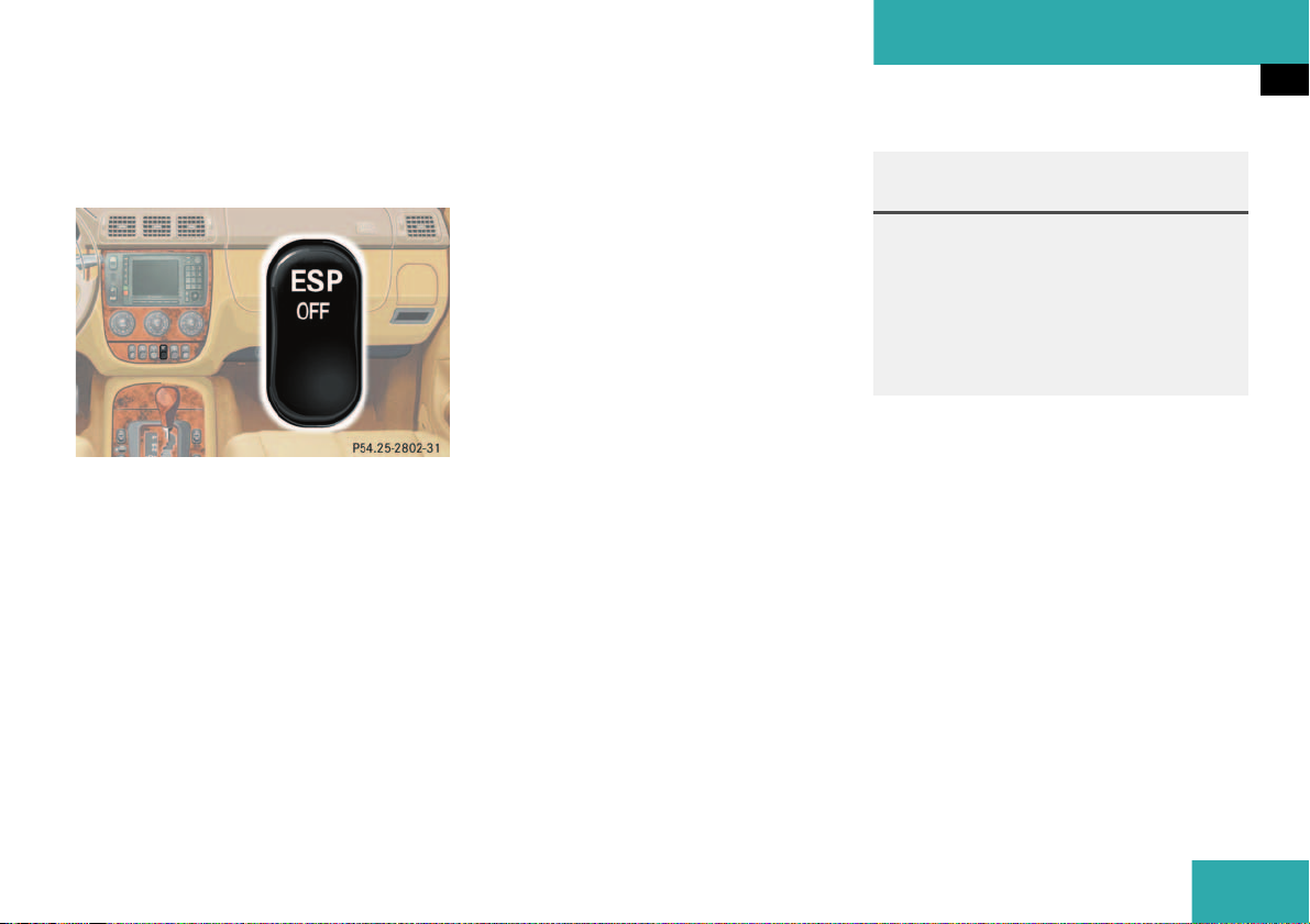
Safety and Security
Driving and safety systems
The button is located in the upper center
console.
1 ESP on/off
왘 Press upper half of button.
The 4-ETS/ESP warning lamp
v in
the speedometer dial comes on.
Even if the ESP has been turned off, it is
still active in the following situations:
앫 when braking
앫 at vehicle speeds between approxi-
mately 24 mph (40 km/h) and 50 mph
(80 km/h), if one drive wheel loses
traction and begins to spin.
The brake is applied until the wheel regains sufficient traction.
The 4-ETS/ESP warning lamp
v, locat-
ed in the speedometer dial, starts to flash
at any speed as soon as the tires lose traction.
Warning! G
When the 4-ETS /ESP warning lamp v is
illuminated continuously, the ESP is
switched off.
Adapt your speed and driving to the prevailing road conditions and to the non-operating
status of the ESP.
Switching on the ESP
왘 Press lower half of button.
The 4-ETS/ESP warning lamp
v in
the speedometer goes out. You are
now again in normal driving mode.
More information can be found in the
“Practical hints” section (
컄 page 224).
77

Safety and Security
Anti-theft systems
Anti-theft systems
Immobilizer
The immobilizer prevents unauthorized
persons from starting your vehicle.
Activating
Removing the key from the steering lock
activates the immobilizer.
Deactivating
Switch on the ignition by turning the key in
the steering lock to position 2.
i
In case the engine cannot be started
(vehicle’s battery is in order), the system is not operational. Contact an authorized Mercedes-Benz Light Truck
Center or call 1-800-FOR-MERCedes
(in the USA), or 1-800-387-0100 (in
Canada).
Anti-theft alarm
Once the alarm system has been armed, a
visual and audible alarm is triggered when
someone:
앫 opens a door
앫 opens the liftgate
앫 opens the hood
The alarm will stay on even if the activating
element (a door, for example) is immediately closed.
The alarm system will also be triggered
when
앫 someone attempts to raise the vehicle
앫 unlocking and opening the driver’s
door with the mechanical key
i
If the alarm stays on for more than
20 seconds, an emergency call is initiated automatically by the Tele Aid system (
컄 page 159) provided Tele Aid
service was subscribed to and properly
activated.
Arming the alarm system
The alarm system is armed after locking
the vehicle with the remote control. The
turn signal lamps blink three times to indicate that the alarm system is activated. A
red lamp in the center console will blink after approximately 10 seconds when the
alarm system is completely armed
(
컄 page 27).
78

Safety and Security
Anti-theft systems
i
If the turn signal lamps do not blink
three times, the tow-away - glassbreackage sensor is malfunctioning or
one of the following elements may not
be properly closed:
앫 a door
앫 the liftgate
앫 the hood
Close the respective element and lock
the vehicle again.
Disarming the alarm system
The alarm system is disarmed when you
unlock your vehicle with the remote control. The turn signal lamps blink once to indicate that the alarm system is
deactivated.
i
The alarm system will rearm automatically again after approximately 40 seconds if one of the doors or the liftgate
is not opened.
Canceling the alarm
To cancel the alarm:
왘 Switch on the ignition by turning the
key in the steering lock to position 2.
or
왘 Press the Œ or ‹ button on the
remote control.
The alarm is cancelled.
Tow-away alarm, glass breakage
sensor
The tow-away alarm and the glass breakage sensor are part of the anti-theft alarm
system.
Once the tow-away alarm is armed, a visual
and audible alarm will be triggered when
someone:
앫 attempts to raise the vehicle
앫 breaks a window and reaches into the
passenger compartment
i
The tow-away protection alarm is triggered, for example, if the vehicle is lifted on one side.
If the alarm stays on for more than
20 seconds, an emergency call is initiated automatically by the Tele Aid system (
컄 page 159) provided Tele Aid
service was subscribed to and properly
activated.
79

Safety and Security
Anti-theft systems
Arming tow-alarm and glass breakage
sensor
When you lock your vehicle, the tow-away
and glass breakage sensor alarm is automatically armed.
Disarming tow-alarm and glass breakage sensor
To prevent triggering the tow-away alarm
feature, switch off the tow-away alarm and
glass breakage sensor before towing the
vehicle, or when parking on a surface subject to movement, such as a ferry or auto
train.
Vehicles with trip computer*
The buttons are located in the overhead
control panel.
1 Reset button
2 Mode button
3 Display
4 Glass breakage sensor
왘 Turn key in steering lock to position 1
(
컄 page 33).
왘 Press button 2.
왘 Return key to position 0 and remove it
from the steering lock.
왘 Within 30 seconds press button 1 or 2.
The display shows
왘 Exit vehicle and lock vehicle with re-
mote control (
OFF
.
컄 page 32).
The tow-away alarm and glass breakage
sensor remain switched off until the key is
inserted in steering lock and turned to
position 1.
80

Safety and Security
Anti-theft systems
Vehicles without trip computer
The buttons are located in the overhead
control panel.
1 Switching off tow-away alarm and glass
breakage sensor
왘 Turn key in steering lock to position 1
(
컄 page 33).
왘 Press the button 2.
왘 Return key to position 0 and remove it
from the steering lock.
왘 Within 30 seconds press button 1 on
the right or left side.
왘 Exit vehicle and lock vehicle with re-
mote control (
컄 page 32).
The tow-away alarm and glass breakage
sensor remain switched off until the key is
inserted in steering lock and turned to
position 1.
81

82

Controls in detail
Locking and unlocking
Seats
Memory function*
Lighting
Instrument cluster
Automatic transmission
Transmission control – LOW RANGE mode
Good visibility
Automatic climate control
Power windows
Sliding/pop-up roof*
Loading
Driving systems
Useful features
83

Controls in detail
Locking and unlocking
In the “Controls in detail” section you will
find detailed information on how to operate the equipment installed in your vehicle.
If you are already familiar with the basic
functions of your vehicle, this section will
be of particular interest to you.
To quickly familiarize yourself with the basic functions of the vehicle, refer to the
“Getting started” section of this manual.
The corresponding page numbers are given at the beginning of each segment.
Locking and unlocking
Remote control with folding key
More information on the remote control
with folding key can be found in the “Getting started” section (
Your vehicle comes supplied with two remote controls with folding key.
The remote control provides an extended
operating range. To prevent theft, however , it is advis a ble to only unl ock t he v ehicl e
when you are in close proximity to it.
The key centrally locks and unlocks:
앫 the doors
앫 the liftgate
앫 the fuel filler flap
컄 page 32).
i
If the key is inserted in the steering
lock, the vehicle cannot be locked or
unlocked with the remote control.
 Panic button (컄 page 70)
1
2
ΠUnlock button
3
‹ Lock button
4 Release button for key
5
Š Unlock button for liftgate
!
To prevent possible malfunction, avoid
exposing the key to high levels of electromagnetic radiation.
84

Controls in detail
Locking and unlocking
Unlocking
i
Unlocking the vehicle with the remote
control deactivates the anti-theft
alarm.
The vehicle will lock again automatically and reactivate the anti-theft system
within approximately 40 seconds of unlocking if neither door nor liftgate is
opened.
Unlocking the driver’s door and fuel
filler flap
왘 Press button Œ once.
All turn signal lamps blink once to indicate that the driver’s door and the fuel
filler flap are unlocked.
Global unlocking
왘 Press button Œ twice.
All turn signal lamps blink once to indicate that all doors, fuel filler flap and
liftgate are unlocked.
Unlocking the liftgate
왘 Press button Š.
Only the liftgate unlocks.
Locking
i
Locking the vehicle with the remote
control activates the anti-theft alarm.
왘 Press button ‹ once
All turn signal lamps blink three times
to indicate that all doors, the liftgate
and the fuel filler flap are unlocked.
i
If the turn signal lamps do not blink
three times, one of the following elements may not be properly closed:
앫 a door
앫 the liftgate
앫 the hood
Close the respective element and lock
the vehicle again.
Warning! G
When leaving the vehicle, always remove the
key from the steering lock, and lock your vehicle. Do not leave children unattended in
the vehicle, or with access to an unlocked
vehicle. Unsupervised use of vehicle equipment may cause an accident and/or serious
personal injury.
85

Controls in detail
Locking and unlocking
!
If you can no longer lock or unlock the
vehicle with the remote control, then
the batteries in the remote control are
discharged, the remote control is malfunctioning or the vehicle battery is
drained.
앫 Use the folding key to unlock or
lock the doors and the liftgate.
앫 Check the vehicle battery
(
컄 page 261).
앫 Replace batteries (컄 page 243).
앫 Synchronize the remote control
(
컄 page 244).
If the remote control is malfunctioning,
contact an authorized Mercedes-Benz
Light Truck Center.
Loss of remote control with folding key
If you lose a remote control or the folding
key, you should do the following:
왘 Have the remote control deactivated
by an authorized Mercedes-Benz Light
Truck Center.
왘 Report the loss of the remote control or
the folding key immediately to your car
insurance company.
왘 If necessary have the mechanical lock
replaced.
Your authorized Mercedes-Benz Light
Truck Center will be glad to supply you
with a replacement.
Opening the doors from the inside
You can open a locked door from the inside. Open door only when conditions are
safe to do so.
1 Locking knob
2 Inside door handle
왘 Pull on door handle 2.
If a door was locked, locking knob 1
will move up.
86

Controls in detail
Locking and unlocking
i
If the vehicle has previously been
locked from the outside with the remote control, opening a door from the
inside will trigger the alarm.
Opening the liftgate
Warning! G
Only drive with the liftgate closed as, among
other dangers such as visibility blockage,
exhaust fumes may enter the vehicle interior.
!
A minimum height clearance of 7 ft.
(2.15 m) is required to open the liftgate.
Opening the liftgate from outside
1 Grip molding
2 Handle
왘 Pull on handle 2.
왘 Swing the liftgate upward by using the
grip molding.
Opening the liftgate from inside
The release lever is located on the inside of
the liftgate.
1 Handle
2 Catch
왘 For unlocking the liftgate move the
catch 2 to the right.
왘 Pull handle 1 down and swing liftgate
upward.
i
For locking the liftgate move the
catch 2 to the left.
87

Controls in detail
Locking and unlocking
Warning! G
Closing the liftgate
When leaving the vehicle, always remove the
key from the steering lock and lock the vehicle. Do not leave children unattended in the
vehicle. Children could open the liftgate
from inside, which could result in an accident and/or serious personal injury.
Warning! G
When closing the liftgate, use extreme caution not to catch hands or fingers. Be especially careful when small children are
around.
Do not close the liftgate from the inside by
pulling on the handle.
1 Recessed grip
2 Grip molding
왘 Pull down on recessed grip 1.
왘 Close liftgate by using grip molding 2.
88

Controls in detail
Locking and unlocking
Automatic central locking
The doors and the liftgate automatically
lock when the ignition is switched on and
the left front wheel turns at vehicle speeds
of approximately 9 mph (15 km/h) or
more.
If one of the front doors is then opened
from the inside, the vehicle is unlocked
centrally unless only the driver's door was
previously unlocked.
i
The doors unlock automatically after an
accident if the force of the impact exceeds a preset threshold.
To prevent the vehicle door locks from
locking, deactivate the automatic central locking when the vehicle
앫 is pushed or
앫 is on a test stand
The central locking button is located on
the lower center console.
Central locking button
1 Locking
2 Unlocking
Activating
왘 Check that the ignition is switched on.
All the lamps in the instrument cluster
light up.
왘 Press and hold upper part 1 of the cen-
tral locking button for approximately
six seconds.
The automatic central locking is activated.
Deactivating
왘 Check that the ignition is switched on.
All the lamps in the instrument cluster
light up.
왘 Press and hold lower part 2 of the cen-
tral locking button for approximately
six seconds.
The automatic central locking is deactivated.
89

Controls in detail
Locking and unlocking
Locking and unlocking from the inside
You can lock or unlock the vehicle from inside using the central locking switches.
This can be useful, for example, if you want
to unlock the passenger door from the inside or want to lock the vehicle before
starting to drive.
i
You can open a locked door from the
inside. Open door only when conditions
are safe to do so.
If you have locked the vehicle with the
remote control, the central locking
switch does not work.
Locking
왘 Press upper part 1 of central locking
button (
컄 page 89).
If all the doors are closed, the vehicle
locks.
Unlocking
왘 Press lower part 2 of central locking
button (
컄 page 89).
The vehicle unlocks, if the vehicle was
not previously centrally locked with the
remote control.
Warning! G
When leaving the vehicle, always remove the
key from the steering lock and lock the vehicle. Do not leave children unattended in the
vehicle, or with access to an unlocked vehicle. Unsupervised use of vehicle equipment
may cause an accident and/or serious personal injury.
90

Seats
Information on seat adjustment can be
found in the “Getting started” section
(
컄 page 34).
Seat heater*
The seat heaters can only be switched on
with the engine running.
The switches are located on the upper center console.
1 Normal heating
2 Rapid heating
Switching on normal seat heating mode
왘 Press upper part 1 of switch.
One indicator lamp in the switch lights
up.
i
The seat heater will be automatically
switched off after approximately
20 minutes.
Switching off normal seat heating
mode
왘 Press upper part 1 of switch again.
The indicator lamp in the switch goes
out.
Switching on rapid seat heating mode
왘 Press lower part 2 of switch.
Both indicator lamps in the switch light
up.
Controls in detail
Seats
i
The system switches over to normal
heating mode after approximately five
minutes. Only one indicator lamp remains lit.
Switching off rapid seat heating mode
왘 Press lower part 2 of switch again.
Both indicator lamps in the switch go
out.
!
If one or both of the lamps on the seat
heater switch are blinking, there is insufficient voltage available since too
many electrical consumers are turned
on. The seat heater switches off automatically.
The seat heater will switch back on
again automatically as soon as sufficient voltage is available.
91

Controls in detail
Seats
Removing and installing head
restraints
Warning! G
For your protection, drive only with properly
positioned head restraints.
Adjust head restraint to support the back of
the head approximately at ear level.
Do not drive the vehicle without the seat
head restraints. Head restraints are intended to help reduce injuries during an accident.
Removing head restraint
1 Lock button
왘 Pull head restraint to its highest posi-
tion
왘 Press lock button 1 and pull out head
restraint.
i
The head restraint(s) should be stored
beneath the cargo floor plates
(
컄 page 144).
Installing head restraint
왘 Insert head restraint and push it down
to the stop.
왘 Press lock button 1 and adjust head re-
straint down to the desired position
(
컄 page 36).
92

Controls in detail
Seats
Rear seats
Warning! G
Do not adjust the rear seats while driving.
Always seat in an upright position and the
seat belts are properly positioned on the
body. Your seat must be adjusted so that
you can correctly fasten your seat belt.
Adjust head restraint to support the back of
the head approximately at ear level.
Never place hands under the seat or near
any moving parts while a seat is being adjusted.
The rear seats are divided asymetrically.
To enlarge the cargo area you can adjust
the left and right part separately. The following changes are possible:
앫 moving the seat fore and aft
앫 folding down the backrest
앫 lowering the seat
Adjusting rear seat fore and aft
1 Release lever
왘 Pull release lever 1 in direction of ar-
row.
왘 Slide seat to the desired position until
it locks in place.
Warning! G
Failure to assure that seats are locked into
place could result in an increased chance of
injury in an accident.
Folding down the backrest
1 Lock button
왘 Close cup holder in rear center console
(
컄 page 155).
왘 Move front seats forward. Manual seat
(
컄 page 35) or power seat (컄 page 37).
왘 Slide seat forward.
왘 Remove head restraint(s) (컄 page 92).
왘 Pull lock button 1 up and fold backrest
forward until it locks in place.
The red backrest lock indicator at lock
button 1 is not visible in the locked position.
93

Controls in detail
Seats
Folding up the backrest
왘 Pull lock button 1 up and unfold back-
rest until it locks in place.
Make sure that the seat belt is not
caught in the seat.
왘 Check for secure locking by pulling and
pushing on the backrest.
The red backrest lock indicator at lock
button 1 is not visible in the locked position.
왘 Install head restraint (컄 page 92).
왘 Slide seat rearward to desired position
(
컄 page 93).
왘 Adjust front seats to desired position.
Manual seats (
seats (
컄 page 37).
컄 page 35) and power
Lowering the rear seat
1 Release button
2 Lever
3 Release lever
왘 Close cup holder in rear center console
(
컄 page 155).
왘 Move front seats forward. Manual seat
(
컄 page 35) or power seat (컄 page 37).
왘 Press and hold release button 1 to un-
lock lever 2.
왘 Pull lever 2 in direction of arrow.
왘 Pull release lever 3 and push down rear
seat until it locks in place.
왘 Fold down the backrest (컄 page 93).
왘 Adjust front seats to desired position.
Manual seats (
seats (
컄 page 37).
컄 page 35) and power
Folding up the rear seat
왘 Move front seats forward. Manual seat
(
컄 page 35) or power seat (컄 page 37).
왘 Pull release lever 3 and raise rear seat
until it locks in place.
Warning! G
Failure to assure that seats are locked into
place could result in an increased chance of
injury in an accident.
94

Controls in detail
Seats
Easy entry/exit feature*
The easy entry/exit feature allows access
to the third row seats*. The right cargo
floor plate must be removed (
컄 page 144).
Warning! G
Never drive with the second row right seat
folded forward (easy entry/exit feature). It
could open and fold back unintentionally.
Folding rear seat forward
1 Lever
왘 Move right seat forward. Manual seats
(
컄 page 35) and power seats
(
컄 page 37).
왘 Move rear seat forward (컄 page 93).
왘 Push head restraint fully down and tilt
it forward.
왘 Fold backrest forward (컄 page 93).
왘 Pull lever 1 up and fold the rear seat
forward.
Resetting rear seat
왘 Pull down on seat bench until it locks
into place.
왘 Pull lock button 1 (컄 page 93) up and
unfold backrest until it locks into place.
왘 Pull down on seat bench until it locks
into place.
왘 Check for secure locking by pulling and
pushing on the backrest.
The red backrest lock indicator at lock
button 1 (
컄 page 93) is not visible in
the locked position.
왘 Move the rear and front seats in de-
sired position.
왘 Pull up and adjust head restraint
(
컄 page 36).
95

Controls in detail
Seats
Third row seats* Folding down single seat
Warning! G
For your protection, drive only with properly
positioned head restraints.
Adjust head restraint to support the back of
the head approximately at ear level.
Failure to assure that seats are locked into
place could result in an increased chance of
injury in an accident.
Never place hands under seat or near any
moving parts while a seat is being adjusted.
1 Head restraint
2 Hook
3 Tensioner
4 Hook and loop strip
왘 Remove cargo floor plate
(
컄 page 144).
왘 Remove head restraint 1 from seat
cushion.
왘 Lift tensioner 3 upward to a horizontal
position to release tension of the belt.
왘 Disengage hook 2 while holding onto
the seat firmly with one hand.
왘 Attach belt at hook and loop strip 4 on
underside of seat.
5 Backrest release
6 Seat release
왘 Fold seat down until it locks securely in
place.
The red marking on the seat release
should 6 not be visible.
왘 Store cargo floor plates inside the
backrest (
왘 Pull backrest release 5 and unfold
컄 page 144).
backrest until it locks securely in place.
왘 Install head restraint 1 in backrest
(
컄 page 92).
96

Controls in detail
Seats
Storing single seat
왘 Remove head restraint from backrest
(
컄 page 92).
왘 Pull backrest release 5 and fold back-
rest forward until it locks securely in
place.
왘 Remove cargo floor plates from the
backrest.
왘 Pull seat release 6 (컄 page 96) and
fold seat up.
왘 Disengage belt and engage hook 2
(
컄 page 96) in ceiling mount.
왘 Pull on free end of belt until tight.
왘 Install head restraint in openings pro-
vided in seat cushion.
왘 Install cargo floor plates (컄 page 144).
Warning! G
After folding the seats up, manually place
the lap belt portion of the seat belt behind
the seat (arrow). Otherwise, the lap belt may
be subject to damage and could rip.
97

Controls in detail
Seats
Removing single seat
1 Hook
2 Tensioner
3 Hook and loop strip
4 Release lever
왘 Lift tensioner 2 upward to a horizontal
position to release tension of the belt.
왘 Disengage hook 2 while holding onto
the seat firmly with one hand.
왘 Attach belt at hook and loop strip 3 on
underside of seat.
왘 Move release lever 4 upward and re-
move seat.
Installing single seat
왘 Place seat into the mounting clamps
and click the seat into place.
98

Memory function*
!
Prior to operating the vehicle the driver
should check and adjust the seat
height, seat position fore and aft, and
seat backrest angle if necessary, to ensure adequate control, reach and comfort. The head restraint should also be
adjusted for proper height. Also see airbag section (
positioning.
In addition, adjust the steering wheel to
ensure adequate control, reach, operation and comfort. Both the inside and
outside rear view mirrors should be adjusted for adequate rear vision.
Fasten seat belts. Infants and small
children should be seated in a properly
secured restraint system that complies
with U.S. Federal Motor Vehicle Safety
Standard 213 and 225 and Canadian
Motor Vehicle Safety Standard 213 and
210.2.
컄 page 55) for proper seat
With the memory button you can store up
to three different settings for the driverand passenger seat.
Together with the driver’s seat you can
store the exterior rear view mirrors.
For the front passenger seat you can store
the seat position.
Warning! G
Do not activate the memory function while
driving. Activating the memory function
while driving could cause the driver to lose
control of the vehicle.
Controls in detail
Memory function*
1 Position buttons
2 Memory button
99

Controls in detail
Memory function*
Storing positions in memory
왘 Adjust the seat (컄 page 36) and exteri-
or rear view mirrors (
컄 page 38) to the
desired position.
왘 Push memory button 2.
왘 Release memory button and press one
of the position buttons 1 within three
seconds.
All the settings are stored at the selected position.
Recalling positions from memory
!
Do not operate the power seats using
the memory button if the seat backrest
is in an excessively reclined position.
Doing so could cause damage to front
or rear seats.
왘 Press and hold one of the position
buttons 1 until seat and rear view mirrors have fully moved to the stored positions.
i
Releasing the button immediately
stops movement to the stored positions.
Exterior rear view mirror parking position (passenger side)
For easier parking, you can adjust the passenger exterior rear view mirror so that you
can see the right rear wheel as soon as you
engage reverse gear R.
100
 Loading...