

MERCEDES-Benz
___________________________________________________________________
Service
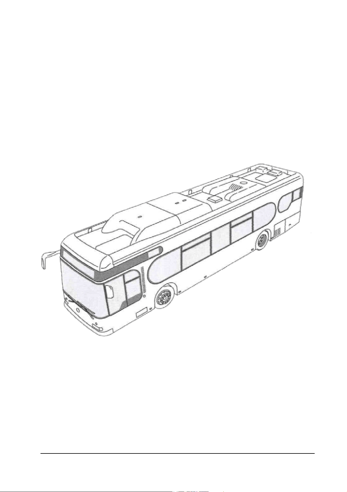
Natural Gas Engine: M 447 hLAG
In Mercedes-Benz City Bus
Click bus for index
The
EGM
engine control unit
Mercedes-Benz AG • Omnibus Product Division •
Status September 2003 (EvoBus-Service / AFT)

Foreword
_____________________________________________________________________
This training document is intended for the technical personnel charged with the maintenance and
servicing of Mercedes-Benz omnibuses with a natural-gas power plant (M 447 hLAG).
In the contents we provide information on the working and operating modes of the engine control unit
(MR) EGM (electronic gas engine) of the M 447 hLAG.
ZCRB0A01
(
).
The specified part number serve only mark marking and distinguishing individual components. When
ordering spare parts, the part numbers should always be taken from the spare parts documentation.
This training document resulted as part of the temporary special measure "Support Start-Up Safeguarding
for M 447 hLAG" and was supplemented with the new diagnostic functions of the software 14B_001. It is
not subject to the updating service. All information correspond to the status at the time of printing.
Other applicable documents (Service – EvoBus)
Details are based on the software version 14B_001
Title
Operating Manual (Omnibus Model O 530 – Citaro ÜSTRA)
On-Board-Diagnose (Omnibus Model O 530 – Citaro ÜSTRA)
Maintenance Sheets, Maintenance Manual (Omnibus Model O 530 – Citaro ÜSTRA)
DC Intranet (description of the natural gas Citaro and the CNG components)
September, 2003
Status September 2003 (EvoBus-Service / AFT) Page: 2 of 83

_____________________________________________________________________
°DK
ABS
AGN
ATL
ATLR
BS
CAN
CNG
DK
DKS
DRB
EDW
EGM
EPW
EV
FPS
FR
FSP
H-Leitung
HW
IBIS
Kl.
KR
KW
KWS
KW-Sensor
L-Leitung
LLR
LMR
LSU
MR
NR
NW
NW-Sensor
OBD
OT
PLD
Prop.-Ventil (PV)
PWM
SAS
SG
SW
TV
WS
ZL
Abbreviations
Grad DrosselKlappe (Degrees of Throttle Valve)
AntiBlockierSystem – Traction Control (Antilock Braking System)
Automatisches Getriebe Nutzfahrzeug
(Automatic Transmission for Commercial Vehicle)
AbgasTurboLader (Exhaust-Gas Turbocharger)
AbgasTurboLaderRegler (Exhaust-Gas Turbocharger Controller)
Brems-Steuerung (Braking Control)
Controller Area Network
Compressed Natural Gas (primarily methane)
DrosselKlappe (Throttle Valve)
DrosselKlappenSteller (Throttle Valve Actuator)
DRehzahlBegrenzung (Speed Limitation)
Elektronische DiebstahlWarnanlage (Electronic Alarm System)
Elektronik GasMotor (Motorregelung des Erdgasmotors)
Elektronik GasMotor (Engine Control of Natural-Gas Engine)
ElektroPneumatischerW
EingasVentil (Gas Injector)
Flexibel Programmierte Steuerung (Flexibly Programmed Controller)
FahrzeugRegelung (Vehicle Control)
FehlerSPeicher (Fault Memory)
High-Leitung (CAN - High Line)
HardWare
Integriertes Bord InformationsSystem
(Integrated On-Board Information System)
Klemme (Terminal)
KlopfRegelung (Knock Control)
KurbelWelle (Crankshaft)
KnickWinkelSteuerung (Knee Angle Control)
Drehzahlaufnehmer an der KurbelWelle (Speed Sensor on Crankshaft)
Low-Leitung (CAN - Low Line)
LeerLaufRegler (Idling Controller)
LambdaMagerRegler (Lambda Lean Controller)
LambdaSondeUniversal (Universal Lambda Probe - Broadband Probe)
MotorRegelung (Engine Control)
NiveauRegelung (Level Control)
NockenWelle (Camshaft)
Drehzahlaufnehmer an der NockenWelle
OnBoardDiagnose (On-Board Diagnosis)
Oberer Totpunkt (Top Dead Centre)
Pumpe-Leitung-Düse
(Pump Line Nozzle - Engine Control of Diesel Engine)
ProportionalVentil (Proportional Valve)
PulsWeitenModulation (Pulse Width Modulation)
SchubAbSchaltung (Overrun Fuel Cut-Off)
SteuerGerät (Control Unit)
SoftWare
TastVerhältnis (Pulse Duty Factor)
WartungsSystem (Maintenance System)
Zusatz-Lenkung (Additional Steering)
andler (Electropneumatic Converter)
Status September 2003 (EvoBus-Service / AFT) Page: 3 of 83

Table of Contents
To forward directly to relevant section, click on BOLD sections headings _____________________
1 Natural Gas Engine M 447 hLAG 8
2 Functional Description of EGM 11
2.1 Introduction 11
2.2 Torque control 13
2.2.1 Engine protection functions 14
2.2.2 Idling control 27
2.3 Engine state detection 28
2.4 Cylinder filling 28
2.4.1 Throttle valve control 29
2.4.2 Throttle valve diagnosis 30
2.4.3 Turbocharger control 31
2.4.4 Turbocharger diagnosis 34
2.5 Gas injection 35
2.5.1 Gas mass calculation during starting 35
2.5.2 Gas mass calculation in normal case 35
2.5.3 Lambda control 37
2.5.4 Lambda control diagnosis 38
2.5.5 Overrun fuel cut-off (SAS) 38
2.5.6 Switch-on conditions for gas injection 38
2.6 Ignition 40
2.6.1 Firing angle in starting mode 40
2.6.2 Firing angle determination in idling mode 40
2.6.3 Firing angle determination in partial-load and full-load mode 40
3 Electrical Description of EGM 42
3.1 System interface overview 42
3.1.1 Block diagram 42
3.1.2 Connector assignment of EGM and ignition modules 43
3.1.3 Power supply of EGM 45
3.1.4 Power supply of ignition module 46
3.2 Sensor technology 47
3.2.1 Active sensors 47
3.2.2 Special sensors 47
3.2.3 Passive sensors 48
3.3 Digital inputs 49
3.3.1 Terminal 15 49
3.3.2 Terminal 50 49
3.3.3 Service switch Start/Stop 49
3.4 Actuator technology 50
3.4.1 Gas injectors 50
3.4.2 Gas injector actuation 50
3.4.3 Proportional valve actuation 52
3.4.4 Lambda heating actuation 52
3.4.5 High-pressure cut-off valve actuation 52
3.4.6 Ignition module actuation 52
Status September 2003 (EvoBus-Service / AFT) Page: 4 of 83

Table of Contents
_____________________________________________________________________
4 Diagnosis 54
4.1 Reading measured values 54
4.1.1 Target engine torque (FR) 55
4.1.2 Maximum current engine torque 55
4.1.3 Actual engine torque 55
4.1.4 Gas injection angle (Cylinder 1) 55
4.1.5 Angle for start of gas delivery (Cylinder 1) 55
4.1.6 Current target control speed 56
4.1.7 Current final limit speed 56
4.1.8 Control-speed target value (FR) 56
4.1.9 Redundant speed (Ter. W) (FR) 56
4.1.10 Engine speed 56
4.1.11 Exhaust-gas temperature 57
4.1.12 Vehicle speed (FR) 57
4.1.13 Coolant temperature 58
4.1.14 Gas temperature 59
4.1.15 Calculation of gas pressure 60
4.1.16 Calculation of engine oil level 61
4.1.17 Oil temperature 61
4.1.18 Charge-air temperature 62
4.1.19 Boost pressure 63
4.1.20 Atmospheric air pressure 64
4.1.21 Oil pressure 65
4.1.22 Throttle-valve target position 66
4.1.23 Throttle-valve actual position 66
4.1.24 Lambda target value 66
4.1.25 Lambda actual value 66
4.1.26 Lambda-probe heating current 66
4.1.27 Lambda correction factor 67
4.1.28 Air mass 67
4.1.29 Gas mass 67
4.1.30 Firing angle (Cylinder 1) 67
4.1.31 Turbocharger pulse duty factor 67
4.1.32 Battery voltage 67
4.2 Reading binary values 68
4.3 EGM-specific Customer Service routines 71
4.3.1 Temporarily switch off LMR 71
4.3.2 Switch-off of gas injectors 72
4.3.3 Cylinder-selective ignition switch-off 72
4.3.4 Temporarily switch off engine run-on 73
4.3.5 Manual compression test 73
5 Checking EGM 74
5.1 Troubleshooting 74
5.1.1 Engine fails to start 74
5.1.2 Engine cannot be switched off 74
5.1.3 Increased engine idling speed 74
5.1.4 Reduced engine output 75
5.1.5 Rough engine running, traction interruption 75
5.2 Special tools 76
5.3 Circuit diagram of M 447 hLAG 76
5.4 Engine performance data 78
Status September 2003 (EvoBus-Service / AFT) Page: 5 of 83

Table of Contents
_____________________________________________________________________
5.5 Safety precautions when working on EGM 79
6 Appendix 80
6.1 Pulse width modulated signal 80
6.2 Overview of bus systems (EvoBus) 81
7 Index 82
Status September 2003 (EvoBus-Service / AFT) Page: 6 of 83

List of Illustrations
_____________________________________________________________________
Overall system of natural gas engine........................................................................................................ 10
Basic EGM functions ................................................................................................................................ 12
Engine protection: charge-air temperature............................................................................................... 15
Engine protection: coolant temperature................................................................................................... 16
Engine protection: turbocharger overpressure ......................................................................................... 17
Engine protection: boost-pressure substitute value formation ................................................................. 18
Engine protection: Crankshaft emergency-running mode (dual ignition)................................................... 19
Engine protection: Camshaft emergency-running mode (failure of crankshaft signal) .............................. 20
Engine protection: lambda lean-controller probe...................................................................................... 21
Engine protection: gas injection............................................................................................................... 22
Engine protection: ignition ....................................................................................................................... 23
Engine protection: oil pressure pre-warning threshold ............................................................................. 24
Engine protection: oil-pressure warning threshold ................................................................................... 25
Idling control: target idling speed............................................................................................................. 27
Throttle valve control: TV = f(throttle valve position)................................................................................ 29
Schematic diagram of wastegate actuation.............................................................................................. 31
Switch-on conditions for boost-pressure control...................................................................................... 32
Switch-on threshold for boost-pressure control ....................................................................................... 33
Switch-off threshold for boost-pressure control....................................................................................... 33
Overview: gas mass calculation in normal operation................................................................................ 36
Release of gas injection and actuation of gas cut-off valve ...................................................................... 39
Function overview of firing angle calculation............................................................................................ 41
Block diagram for electrical description:.................................................................................................. 42
Actuation phases and current curve of gas injectors................................................................................ 51
Principle of ignition actuation:.................................................................................................................. 53
Determining the target engine torque ...................................................................................................... 55
Characteristic curve: Exhaust-gas temperature sensor ............................................................................57
Characteristic curve: Coolant temperature sensor................................................................................... 58
Characteristic curve: Gas temperature sensor ......................................................................................... 59
Characteristic curve: Gas pressure sensor............................................................................................... 60
Characteristic curve: Oil temperature sensor........................................................................................... 61
Characteristic curve: Charge-air temperature sensor............................................................................... 62
Characteristic curve: Boost pressure sensor............................................................................................ 63
Characteristic curve: Atmospheric pressure sensor................................................................................. 64
Characteristic curve: Oil pressure sensor................................................................................................. 65
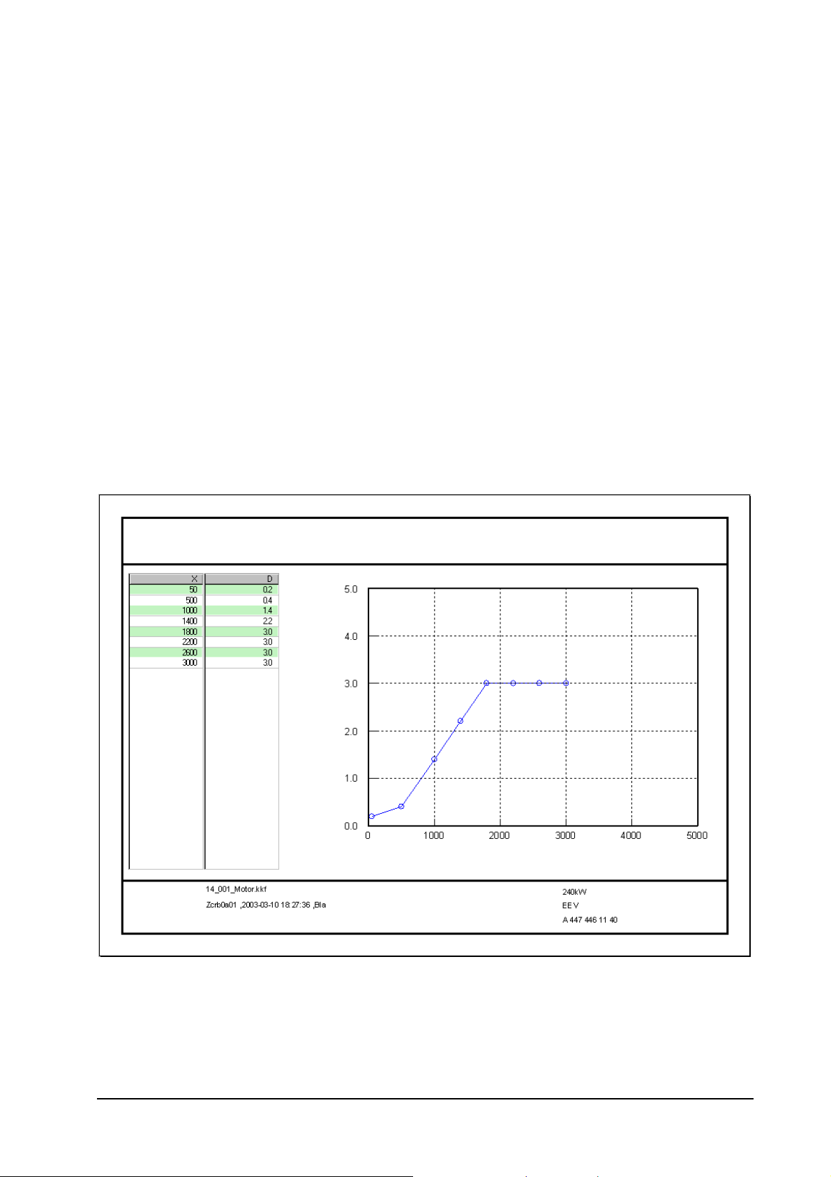
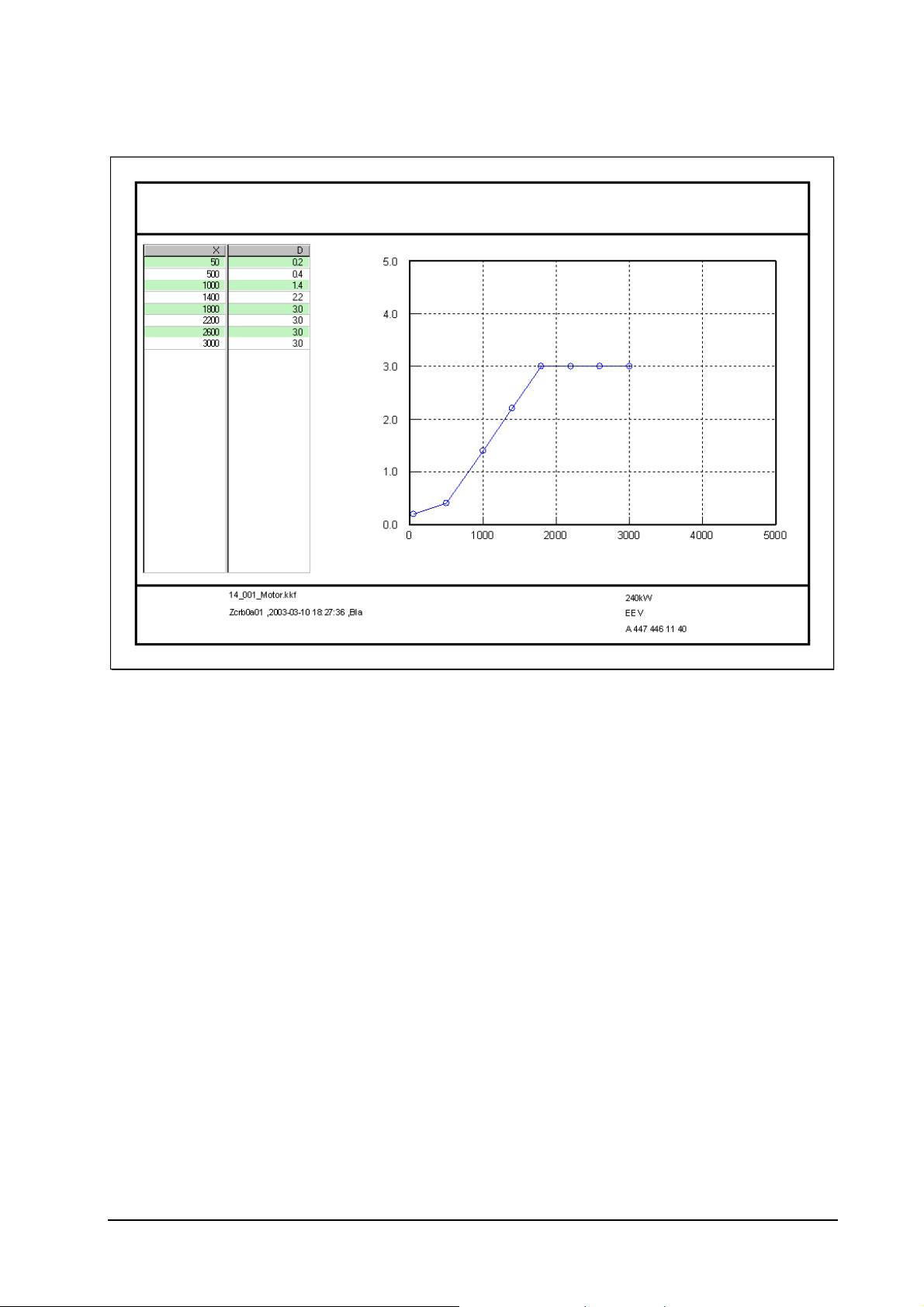
Performance graph for O 447 hLAG, 240 kW........................................................................................... 78
Performance graph for M 447 hLAG, 185 kW .......................................................................................... 78
Drawing: pulse width modulated signal.................................................................................................... 80
Overview of bus systems (EvoBus)........................................................................................................... 81
Status September 2003 (EvoBus-Service / AFT) Page: 7 of 83

The M 447 hLAG Natural-Gas Engine
_____________________________________________________________________
1 Natural Gas Engine M 447 hLAG
The M 447 hLAG is a further development of the M 447 hG and is used in the natural gas Citaro from
Mercedes-Benz and in the CBC chassis.
Technical data of engine:
• 6-cylinder, inline
• Natural gas operation with CNG
• Lean combustion
• Exhaust-gas turbocharger with wastegate control
• Charge air cooling
• Two output variants
240 kW @ 2,000 rpm and 1,250 Nm @ 1,500 rpm
185 kW @ 2,000 rpm and 1,050 Nm @ 1,300 rpm
• Three emission levels
EURO2
EURO4
EEV (Enhanced Environmentally Friendly Vehicles)
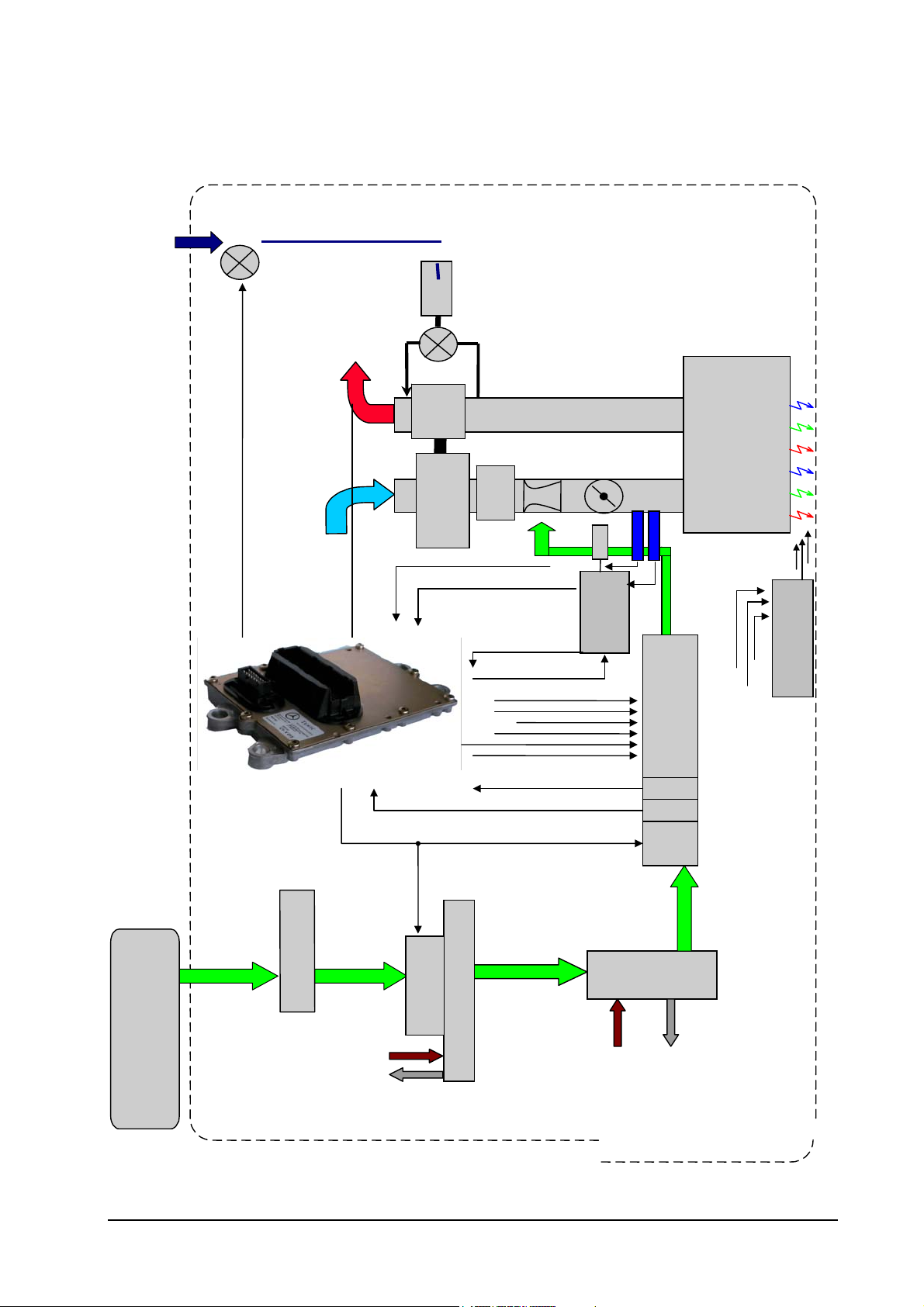
The fuel natural gas (CNG = Compressed Natural Gas) is stored in gas pressure bottles. These are
mounted crosswise on the vehicle roof. During refuelling the CNG is compressed to 200 bar. The CNG
flows to the high-pressure regulator via a high-pressure line. An electrically actuated high-pressure cut-off
valve is located upstream of the pressure regulator. The high-pressure cut-off valve is closed when not
actuated. The high-pressure cut-off valve is actuated by the EGM. The high-pressure regulator forms the
interface between the high-pressure and the low-pressure circuit. The maximum storage pressure of 200
bar is adjusted in the high-pressure regulator to an operating pressure of approx. 8 bar. As heat is
absorbed from the surrounding area when the natural gas expands, the pressure regulator is heated with
the engine coolant. A partial icing-up of the pressure regulator is quite normal. Complete icing-up could
lead to the failure of the pressure regulator.
Next the CNG relaxed to approx. 8 bar is routed through the heat exchanger. In the heat exchanger the
CNG is to be conditioned to approx. 40 °C. The engine coolant also flows through the heat exchanger.
The engine coolant temperature is controlled by a thermostat. The conditioned CNG flows to the injector
block. The electrically actuated low-pressure cut-off valve is located at the inlet of the injector block. The
low -pressure cut-off valve is closed when not actuated. The low-pressure valve is switched parallel to the
high-pressure valve and is also actuated by the EGM. Twelve gas injectors (one pair per cylinder), a gas
pressure and gas temperature sensor are mounted in the injector block. The gas pressure and
temperature are evaluated and monitored by the EGM. The gas injectors are actuated cylinder-selectively
by the EGM to meter the gas quantity fed to the engine. Finally, the exactly metered gas quantity is blown
through the mixer, which is mounted before the throttle valve, into the intake duct of the engine. The
combustible gas-air mixture is prepared in the mixer and the throttle valve.
The natural gas engine is a spark ignition engine. The combustible gas-air mixture must be ignited by
another source. The necessary ignition energy is provided by two ignition modules. Each ignition module
is equipped with three ignition coils. The ignition point is controlled by the EGM and the ignition is
triggered by corresponding actuation of the ignition modules.
Status September 2003 (EvoBus-Service / AFT) Page: 8 of 83

The M 447 hLAG Natural-Gas Engine
_____________________________________________________________________
The M 447 hLAG is a turbocharged engine. The turbocharger is a rigid-geometry turbocharger with a
wastegate. The charge air pressure is controlled for the respective operating point by the EGM. For this
purpose the EGM actuates the electropneumatic converter (EPW) of the wastegate.
The lambda broadband probe is mounted in the exhaust section behind the turbocharger. This determines
the lambda in the exhaust gas. Based on the measured lambda, the EGM can correct the gas injection
accordingly if necessary so that the target lambda is complied with at all operating points (lambda
control).
Status September 2003 (EvoBus-Service / AFT) Page: 9 of 83
_____________________________________________________________________
Overall system of natural gas engine
Pressure control valve
EPW
The M 447 hLAG Natural-Gas Engine
approx. 8 bar
Compressed air
Lambda
Exhaust
gas
Turbine
Compressor
Charge-air temperature
Charge-air pressure
Gas temperatur
Valve
Mixer
LLK
Gas pressure
Engine
Natural-Gas
M 447 hLAG
Flotech
Woodward
block
valve control
cylinder-selective
Injektor
Woodward
T
P
Ignition modules
ignition
cylinder-selective
ND
valve.
(TEMIC)
8 bar
CNG ~
EGM engine control
CNG ~8 bar
CNG Tank
CNG- Filter
approx. 30 to 200 bar
valve
High-pressure
ITT pressure regulator
Engine coolant
Status September 2003 (EvoBus-Service / AFT) Page: 10 of 83
Heat exchanger
Engine coolant
_____________________________________________________________________
2 Functional Description of EGM
2.1 Introduction
Functional Description of EGM
The EGM (electric gas engine) engine control unit is mounted on the engine, and is therefore part of the
engine. Only one basic control unit is required for all offered output variants
1
of the M 447 hLAG. The
EGM is adapted to the corresponding output and engine variant with different programming. An EGM that
is already programmed is considered a special engine component and may not be interchanged between
different engines. An exchange of the EGM can lead to problems ranging from impairment of correct
engine operation to engine and drive train damage. Exchange engines are always delivered complete with
the engine wiring harness and the related EGM engine control
unit.
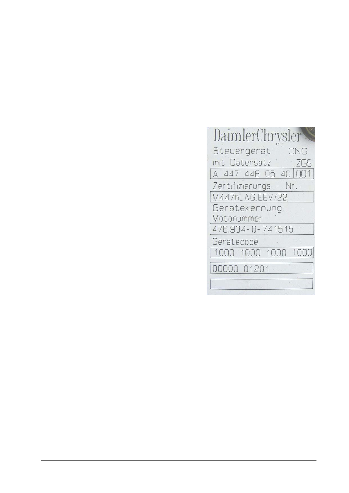
To be able to distinguish between different control units,
each unit is provided with a sticker. The data record number
(1) with which the EGM is programmed is indicated at the top
of the sticker. This data record number should always be
specified when purchasing a replacement.
The EGM engine control unit is an electronic spark-
ignition engine control unit for engines of the 447 and 900
series. The EGM's design is based on the PLD diesel engine
control unit and is virtually identical to the PLD on the
outside. Open and closed-loop control functions which can be
used both for diesel and spark-ignition engines have been
adopted from the PLD in the EGM. Examples include:
• Engine control with torque interface
• Camshaft/crankshaft signal detection
• CAN and ISO-K interfaces
• Oil level sensing
• PIN assignment of vehicle connector
• Service engine switch Start/Stop
• Starter control
The functions specific to spark-ignition engines have been newly developed. The main open and closedloop control functions are:
• Air mass control by electronic throttle valve and boost-pressure control
• Dwell and firing-angle control
• Sequential gas injection with variable start of gas injection
• Lambda control with broadband probe for lambda = 1 and lean operation
• Engine protection functions
• Diagnostic functions
1
The output variants with 185 kW (rigid vehicle) and 240 kW (articulated vehicle) are currently available
Status September 2003 (EvoBus-Service / AFT) Page: 11 of 83
_____________________________________________________________________
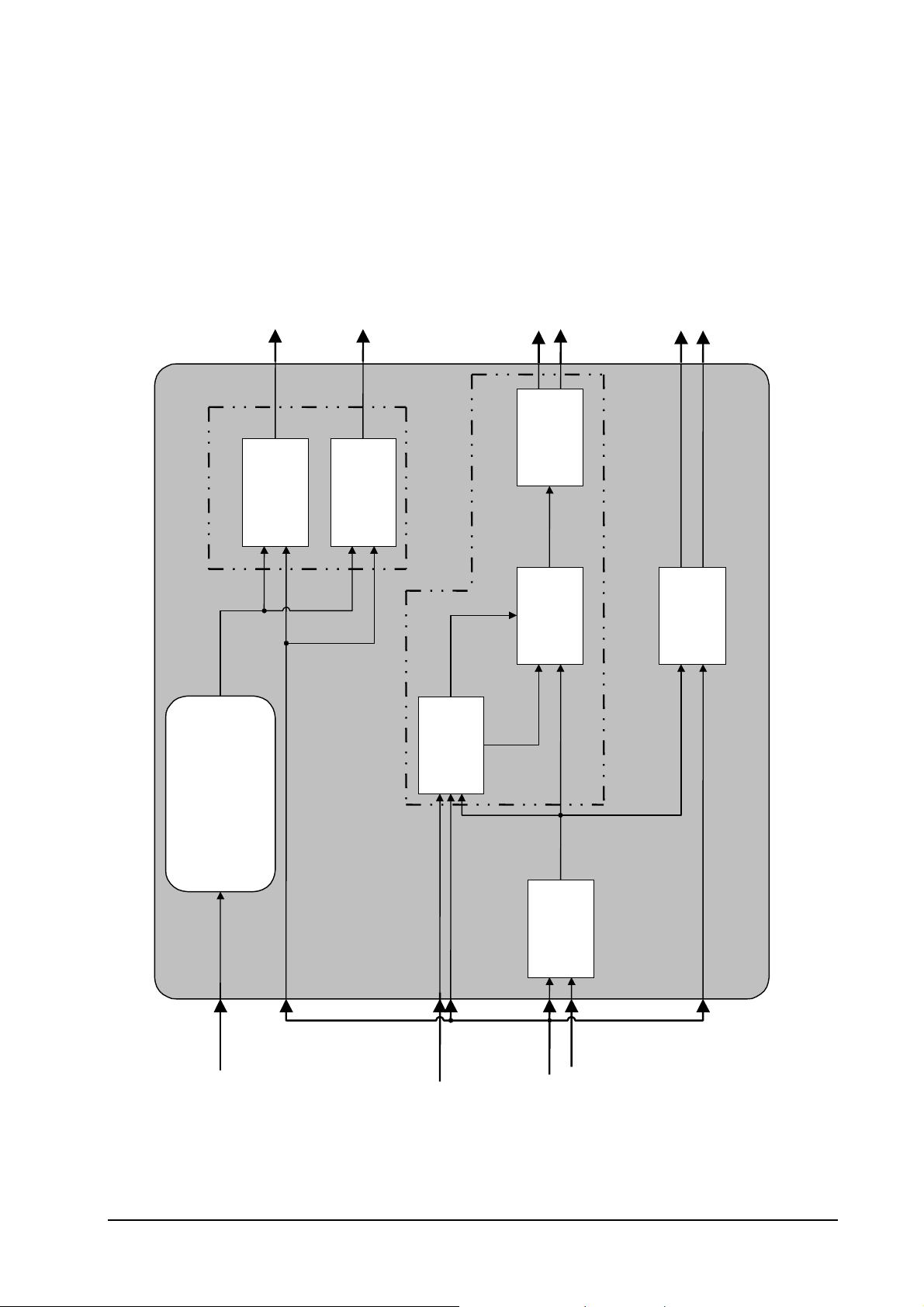
Basic EGM functions
Functional Description of EGM
DK setpoint position
control
Cylinder filling
Throttle valve
ATL pulse duty factor
Turbocharger
control
Lambda-
correction factor
Gas injection
Angle for start
of gas delivery
angle
Injection
Gas mass
Gas mass
calculation
target value
Lambda-
Closing angle
Ignition
Firing angle
Firing angle
calculation
Lambda
control
Gas injection
Speed limitation
Torque interface
Speed final limitation
Engine protection
Idling control
y
y
y
y
Overview of EGM mode of operation
Target engine
torque (FR)
Lambda
actual value
Air mass
Air mass
detection
Engine speed
Boost pressure
Status September 2003 (EvoBus-Service / AFT) Page: 12 of 83

Functional Description of EGM
_____________________________________________________________________
2.2 Torque control
Like the PLD, the EGM is a torque-based engine control unit. The EGM receives the torque specification
from the FR via a CAN bus. The torque specification refers to the engine output shaft and corresponds to
the torque requested by the driver (interpretation of the accelerator pedal position by the FR). With
functioning CAN communication, the EGM actuates the corresponding actuators so that the requested
torque (torque specification) is present at the engine output.
Expressed in simplified terms, this consists of the following steps:
1) Control of cylinder filling
In accordance with the specification target engine torque (FR) and the current engine
speed, the EGM determines the DK target position and the target charge air pressure from
corresponding maps and actuates these accordingly.
2) Determination of air mass
In the next step the air mass present in the cylinders is calculated based on the measured
boost pressure (determination of cylinder filling).
3) Calculation of gas mass to be injected
With the knowledge of the air mass and taking the target lambda and the lambda correction
value into account, the gas mass to be injected is calculated in the next step.
4) Conducting gas injection
The gas injection angle is calculated from the gas mass while taking the operating
conditions into account. The cylinder-selective gas injection begins with the gas-injection
starting angle and ranges over the gas injection angle.
5) Mixture ignition
The firing angle is determined as a function of the air mass and the current engine speed.
The cylinder-selective ignition is realised by corresponding actuation of the ignition
modules.
6) Checking actual lambda (lambda control)
The lambda probe mounted in the exhaust section behind the turbocharger determines the
actual lambda in the exhaust gas. The lambda controller of the EGM compares the target
and the actual lambda and determines the lambda correction factor from the result. This is
taken into account when determining the gas mass.
The combination of air mass (cylinder filling), gas injection mass (gas injection) and firing angle (ignition)
results in the target engine torque (FR) at the engine output shaft requested by the driver. The engine
torque output by the engine is calculated from a map and transferred as the absolute actual engine
torque.
Status September 2003 (EvoBus-Service / AFT) Page: 13 of 83

Functional Description of EGM
_____________________________________________________________________
2.2.1 Engine protection functions
Several functions for protecting the engine under unfavourable engine operating conditions (high coolant
temperature, high charge-air temperature etc.) and in case of errors in the sensor technology, actuators
or mechanical systems are implemented in the EGM engine control unit. These can result in the possible
torque at full load being limited by the engine protection functions. In order not to endanger the engine's
availability, the engine protection functions – with the exception of the engine protection function: Dual
ignition – not active during starting.
The following engine protection functions can be active in the MR EGM:
1) Engine protection: charge-air temperature
In the case of an impermissibly high charge-air temperature, the permissible engine torque is reduced
as a function of the charge-air temperature.
2) Engine protection: coolant temperature
In the case of an impermissibly high coolant temperature, the permissible engine torque is reduced as
a function of the coolant temperature.
3) Engine protection: turbocharger overpressure
In the case of an impermissibly high boost pressure, the permissible engine torque is reduced as a
function of the boost pressure.
4) Engine protection: boost-pressure substitute value formation
If the boost-pressure sensor fails, the engine continues to be operated in the emergency running
mode. The basis for the emergency running mode is an estimated boost pressure. The available engine
torque is limited as a function of the engine speed.
5) Engine protection: camshaft emergency-running mode
If the camshaft signal fails, the engine is operated in the crankshaft emergency running mode with
dual ignition (only if camshaft signal has already failed prior to engine starting). In case of operation
with dual ignition, the available engine torque is limited as a function of the engine speed.
6) Engine protection: camshaft emergency-running mode
If the crankshaft signal fails, the engine is operated in the camshaft emergency running mode. The
available engine torque is limited as a function of the engine speed.
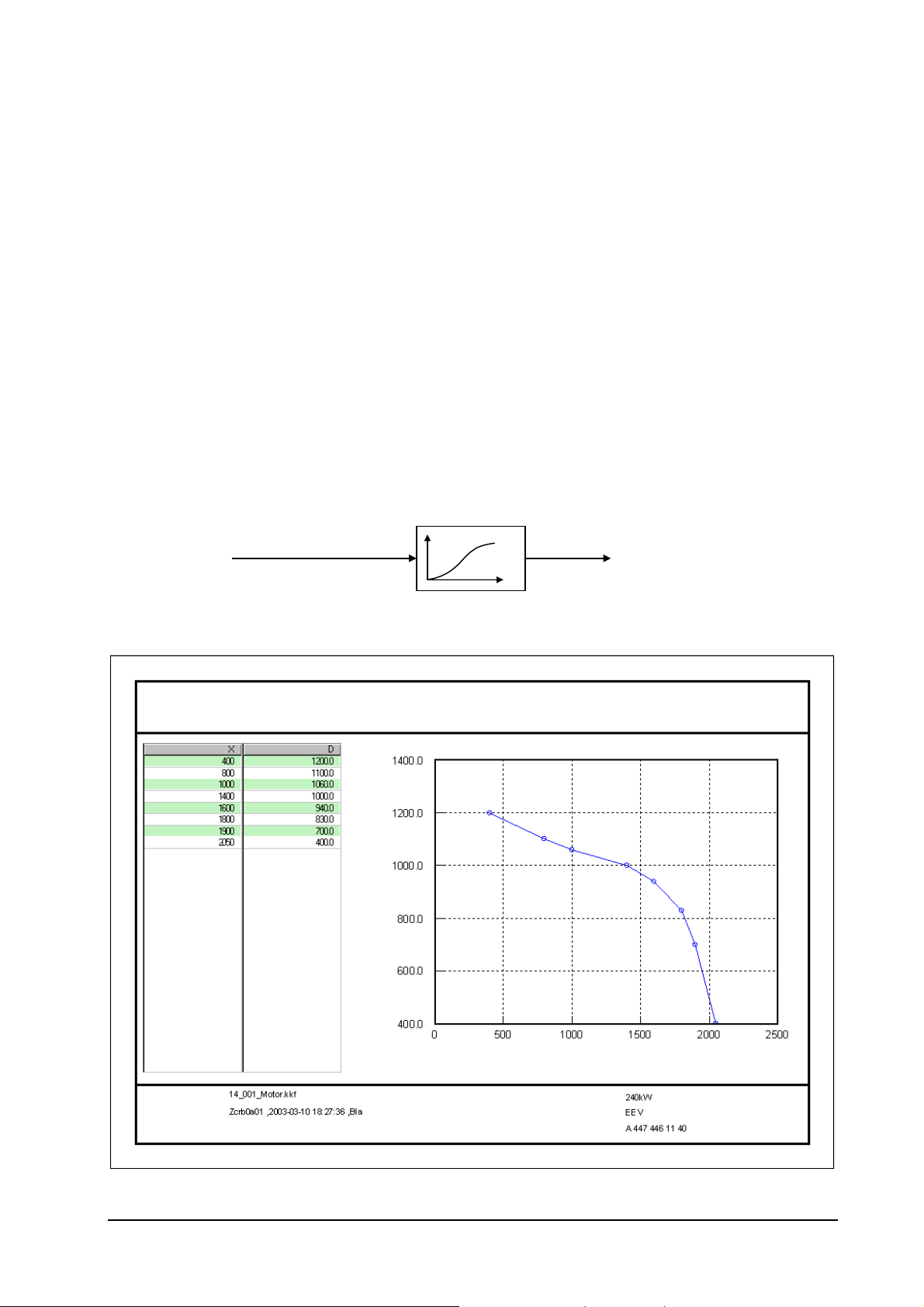
7) Engine protection: lambda lean-controller probe
If the lambda sensor fails, the available engine torque is reduced as a function of the engine speed.
8) Engine protection: gas injection
In case of faults in the gas injection actuators (gas injection valves and supply lines), the
corresponding emergency running measures are initiated and the maximum possible engine torque is
limited as a function of the engine speed.
9) Engine protection: ignition
In case of errors in the actuation of the ignition modules (primary-side), the engine switches over to an
increased idling speed and the available engine torque is greatly limited.
10) Engine protection: oil pressure
For engine protection at a low oil pressure, a two-stage warning concept (similar to that used with the
PLD) has been realised. It is ONLY a warning concept – engine operation remains unchanged (no
affect on engine operation).
11) Engine protection: overspeed
To protect the engine against overspeed, first the throttle valve is closed , and if the engine speed
continues to increase, gas injection is cancelled.
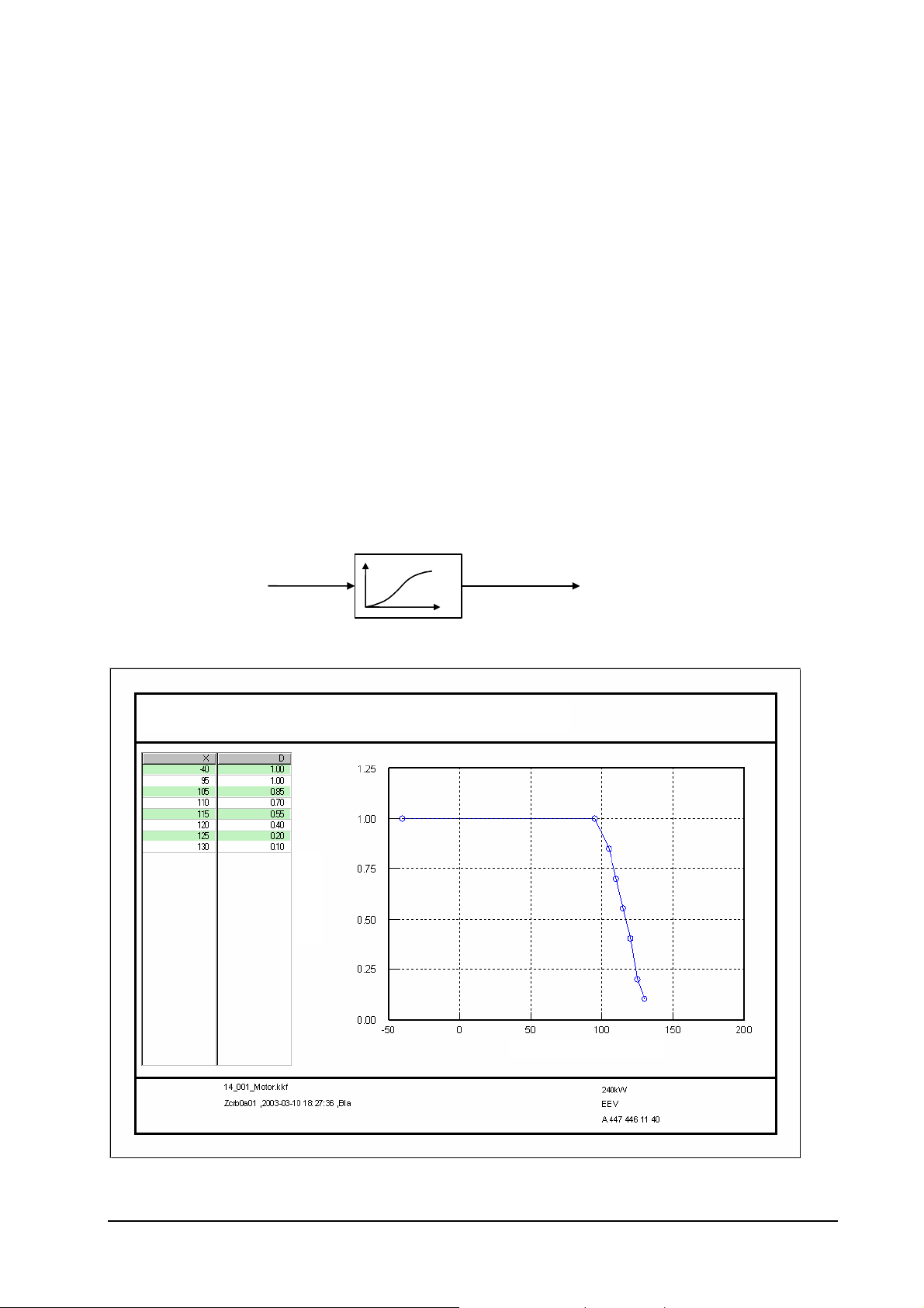
12) Engine protection: exhaust-gas temperature
Status September 2003 (EvoBus-Service / AFT) Page: 14 of 83
Functional Description of EGM
_____________________________________________________________________
To protect the catalyst at excessively high exhaust-gas temperatures, the available engine torque is
limited as a function of the engine speed and exhaust-gas temperature according to the catalyst and
engine speed.
2.2.1.1 Engine protection: charge-air temperature
The engine protection function charge-air temperature is intended to reduce the maximum permissible
engine torque at excessively high charge-air temperatures. The value for the reduction of the available
engine torque is calculated with the engine running from a characteristic curve as a function of the
charge-air temperature and multiplied by the target engine torque.
Engine protection: charge-air temperature
Torque limitation at
Charge-air temperat u re
Title: Service EGM: Motorschutz
File: kd_mts_LLT.vsd
Date of last change:
2001-09-12
charge-air temperatur e
Characteristic curve
Charge air
Limitation factor
MOB - Torque Limitation at Charge-Air Temperature
Factor [-] = f(Charge-air temp.[°C])
Factor
Charge-Air Temperature
Status September 2003 (EvoBus-Service / AFT) Page: 15 of 83
Functional Description of EGM
_____________________________________________________________________
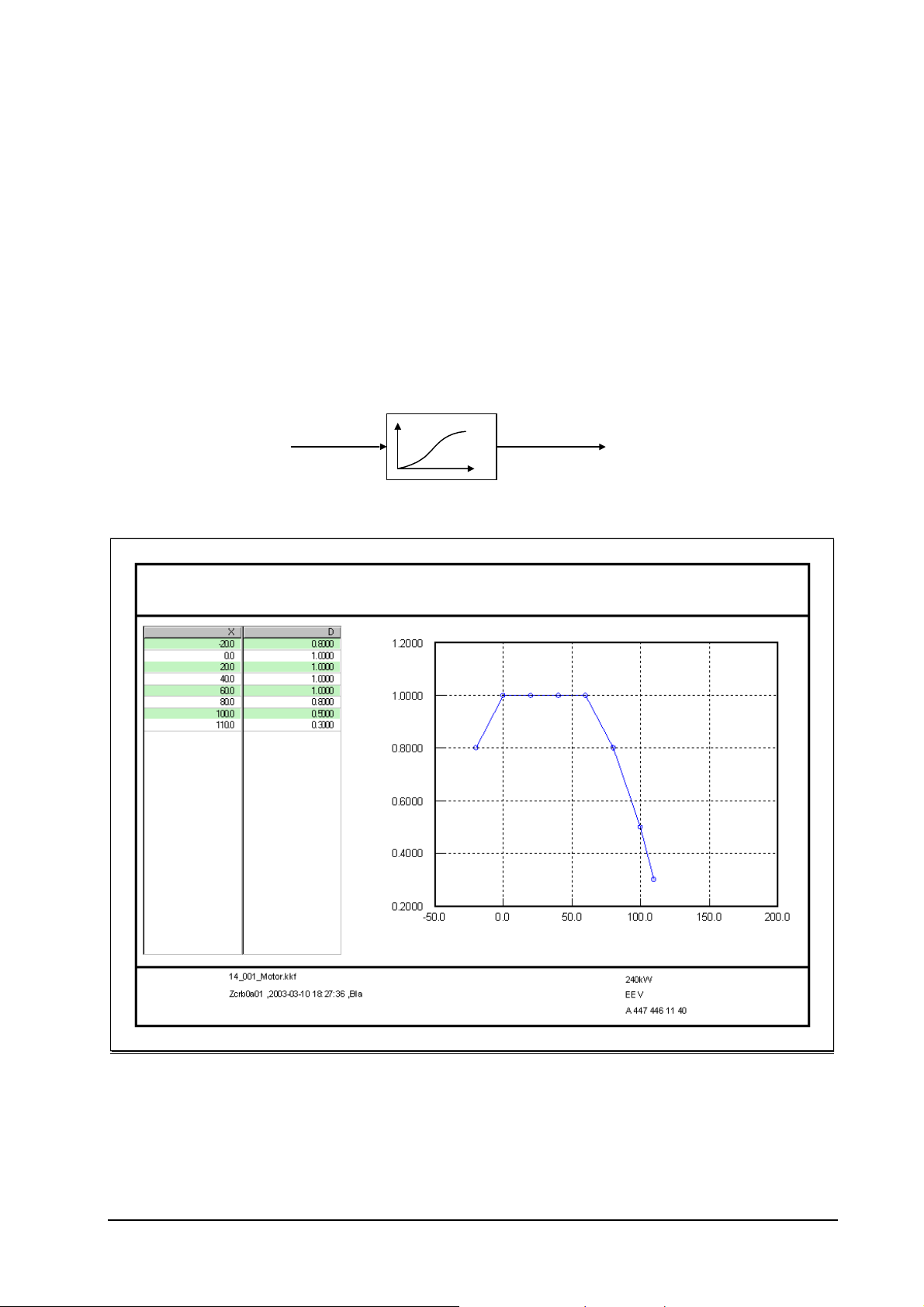
2.2.1.2 Engine protection: coolant temperature
The engine protection function coolant temperature is used to protect the engine against operation at
impermissibly high coolant temperatures. This function consists of two parts which are processed
independently of the engine state.
• Coolant temperature monitoring
If the coolant temperature is higher than 98 °C, then a coolant temperature pre-warning is requested.
To attenuate the pre-warning, it is not cancelled until the coolant temperature is at least 1 °C less
than the pre-warning threshold. If the coolant temperature is higher than 105 °C, then the warning
buzzer is activated. Here as well, a hysteresis of 1 °C is implemented before the warning buzzer
request due to an excessively high coolant temperature is cancelled again when the temperature
drops. When the warning buzzer is requested, the fault 2122 "Coolant temp. too high" is stored in the
fault memory. The coolant temperature is monitored every 40 ms regardless of the engine state.
• Torque reduction
From a characteristic curve as a function of the coolant temperature, a limiting factor for torque
reduction is calculated ("boiling protection"), the target engine torque (FR) is multiplied by this limiting
factor and the engine torque is reduced accordingly.
Engine protection: coolant temperature
Coolant-temperature limitation characteristic curve
Coolant temperature
Title: Service E GM: Motorschutz
File : kd_ mts_ tmot. vsd
Date of la st chang e 2001-09-12
MOB - Torque limitation at coolant temperature
Limitation factor [-] = f(Coolant temperature [°C] )
Limitation factor
Characteristic curve
Coolant temperature
Limitatio n facto r
Engine temperature
Status September 2003 (EvoBus-Service / AFT) Page: 16 of 83
Functional Description of EGM
p
_____________________________________________________________________
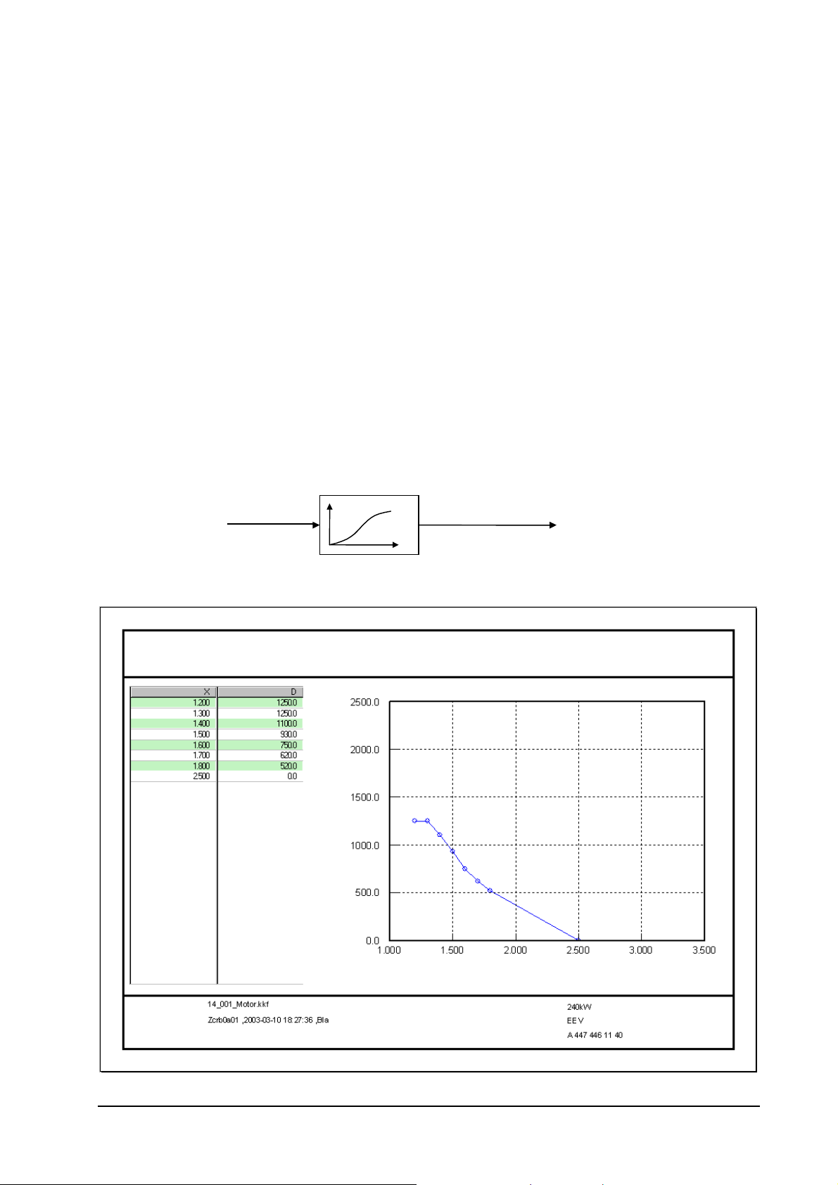
2.2.1.3 Engine protection: turbocharger overpressure
The engine protection function turbocharger overpressure is used to protect the engine during operation
against impermissibly high boost pressures ("turbocharger overpressure"), e.g. in case of a defective
"wastegate".
• Turbocharger overpressure detection
If the actual boost pressure is above the permissible value of 2.35 bar for longer than 15 seconds,
then the event "Boost pressure too high" is detected and the fault code 1820 is entered. This limit
pressure check takes place cyclically every 40 ms. An active overpressure fault is first reset in the
engine state "Engine stopped" with the engine stopped. If the boost-pressure only briefly exceeds the
currently permissible value, the fault debouncing begins again from the start the next time the limit is
exceeded.
• Torque limitation
The full-load torque is limited by a factor dependent on the boost pressure to protect the turbocharger
and the engine.
Engine protection: turbocharger overpressure
Torque limitation with
Boost pressure
turbocharger overpressure
Characteristic curve
Boost
ressure
Limitation torque
Engine protection: overpressure limitation
File: kd_mts_p2.vsd
Date: 29.09.2000
MOB - Torque limitation with charge-air overpressure
Max. target torque [Nm] = f(Boost pressure [bar])
Torque
Boost pressure
Status September 2003 (EvoBus-Service / AFT) Page: 17 of 83
Functional Description of EGM
_____________________________________________________________________
2.2.1.4 Engine protection: boost-pressure substitute value formation
The boost-pressure signal is the most important information of the EGM and the condition for realising
correct operation of the natural gas engine. From the boost-pressure signal the EGM determines the air
mass present in the combustion chambers. Based on this information, the gas mass to be injected is
calculated taking the target lambda into account. If the boost-pressure sensor fails, the EGM must
estimate the air mass in the combustion chambers to continue engine operation. This is only possible in
the engine "intake mode", and therefore the wastegate of the exhaust-gas turbocharger is opened when
the boost-pressure sensor fails to largely prevent turbocharging.
The engine protection function: "Boost-pressure substitute value formation" is run when:
a) the engine control detects a broken wire of the boost-pressure sensor (fault code: 1415) or
b) the engine control detects a short-circuit to earth of the boost-pressure sensor (fault code 1416)
In the case of a fault, the available engine torque is limited as a function of the engine speed.
Engine protection: boost-pressure substitute value formation
MOB - Torque limitation with boost-pressure substitute value formation
Factor [-] = f(Speed [rpm])
Limitation factor
Speed
Status September 2003 (EvoBus-Service / AFT) Page: 18 of 83
Functional Description of EGM
_____________________________________________________________________
2.2.1.5 Engine protection: camshaft emergency-running mode
To detect and evaluate the current crank angle and the engine speed, the
M 447 hLAG is equipped with two inductive speed sensors – one crankshaft sensor and one camshaft
sensor. Both speed sensors are evaluated and monitored by the engine control. As the resolution of the
crankshaft sensor is higher than that of the camshaft sensor (more tooth faces on the crankshaft gear),
the crankshaft signal is normally used for determining the crank angle. The camshaft signal is required for
system synchronisation and when the crankshaft signal fails. If the camshaft signal fails before "system
synchronisation" , the engine control switches into the crankshaft emergency-running mode. In the
crankshaft emergency-running mode the so-called dual ignition (two cylinders are ignited simultaneously)
takes place and the torque reduction is carried out as a function of the engine speed. If the camshaft
sensor fails after "system synchronisation" is carried out, engine operation is maintained without
restriction.
Note: To accelerate the engine run-up during starting, starting is carried out with dual ignition (cylinderselective gas injection and firing of two cylinders).
Engine protection: Crankshaft emergency-running mode (dual ignition)
Torque limitation
Engine speed
Title: Engine protection
File: kd_mts_doppelzündung.vsd
Date of last change: 2001-09-12
with dual ignition
Characteristic curve
Dual ignition
Limitation torque
MOB - Torque limitation with dual ignition / Crankshaft emergency-running mode
Torque [Nm] = f(Speed [rpm])
Torque
Speed
Status September 2003 (EvoBus-Service / AFT) Page: 19 of 83
Functional Description of EGM
_____________________________________________________________________
2.2.1.6 Engine protection: camshaft emergency-running mode
To detect and evaluate the current crank angle and the engine speed, the
M 447 hLAG is equipped with two inductive speed sensors – one crankshaft sensor and one camshaft
sensor. Both speed sensors are evaluated and monitored by the engine control. As the resolution of the
crankshaft sensor is higher than that of the camshaft sensor (more tooth faces on the crankshaft gear),
this sensor is normally used for determining the crank angle. The camshaft signal is required for system
synchronisation and when the crankshaft signal fails.
If the crankshaft signal fails (camshaft emergency-running mode), the crank angle is determined based on
the camshaft signal. Virtually unrestricted engine operation can be maintained. As the crank angle
determination is carried out less accurately with the camshaft sensor than with the crankshaft sensor, the
available engine torque in the camshaft emergency-running mode is limited as a function of the engine
speed.
Engine protection: Camshaft emergency-running mode (failure of crankshaft signal)
Torque limitat ion
Engine speed
Title: Service EGM: Engine protection
File: kd_mts_NW_Notlauf.vsd
Date of last change: 2001-09-12
Camshaft e.-running mode
Characteristic curve
Camshaft
e.-running mode
Limitation factor
MOB - Torque limitation with camshaft e.-running mode
Factor [-] = f(Speed [rpm])
Torque
Speed
Status September 2003 (EvoBus-Service / AFT) Page: 20 of 83
Functional Description of EGM
_____________________________________________________________________
2.2.1.7 Engine protection: lambda lean-controller probe
The engine protection function lambda lean-controller probe is intended to reduce the maximum
permissible engine torque if the lambda correction factor differs too greatly and/or in the case of an
implausible probe heating current.
The engine protection function: "Lambda lean-controller probe" is run when:
c) the engine control has detected an extremely great deviation of the lambda correction factor with the
corresponding fault memory entry 0775: "Control deviation too great" or
d) the engine control has detected an implausible probe heating current with the corresponding fault
memory entry 8417: "Measuring range implausible" .
The value for the reduction of the limit torque is calculated from a characteristic curve as a function of
the engine speed. The engine protection function lambda lean-controller probe is run in the 40 ms time
slice.
Engine protection: lambda lean-controller probe
Torque limitation LMR
manip. variable deviation
Engine speed
Title: Service EGM: Engine protection
File:
Date of last change: 16.09.2003
MOB - Torque limitation with LMR manip. variable deviation
Max. torque [Nm] = f(Speed [rpm])
Torque
Characteristic curve
LMR time-out
Limitation torque
Speed
Status September 2003 (EvoBus-Service / AFT) Page: 21 of 83
Functional Description of EGM
_____________________________________________________________________
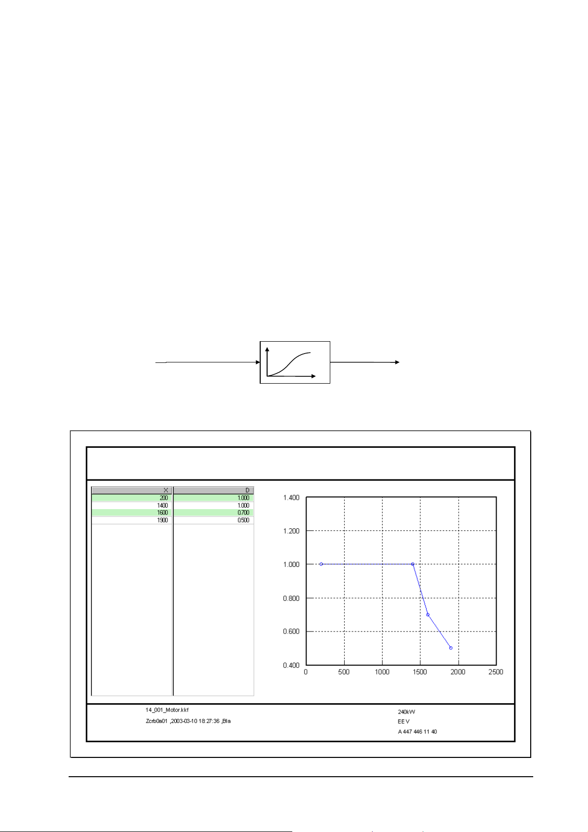
2.2.1.8 Engine protection: gas injection
From the software version 13A, the EGM engine control unit is capable of detecting fault states on the
gas injectors and their wiring. In the case of a fault, corresponding fault codes are stored in the fault
memory and emergency running measures are initiated. As full engine output is not possible in the case
of a failure of individual gas injectors, this is intentionally limited in dependence on the number of failed
gas injectors and the engine speed. The EGM engine control unit is capable of compensating the failure of
up to three "gas injector pairs"; if an additional injector pair fails, the engine is switched off.
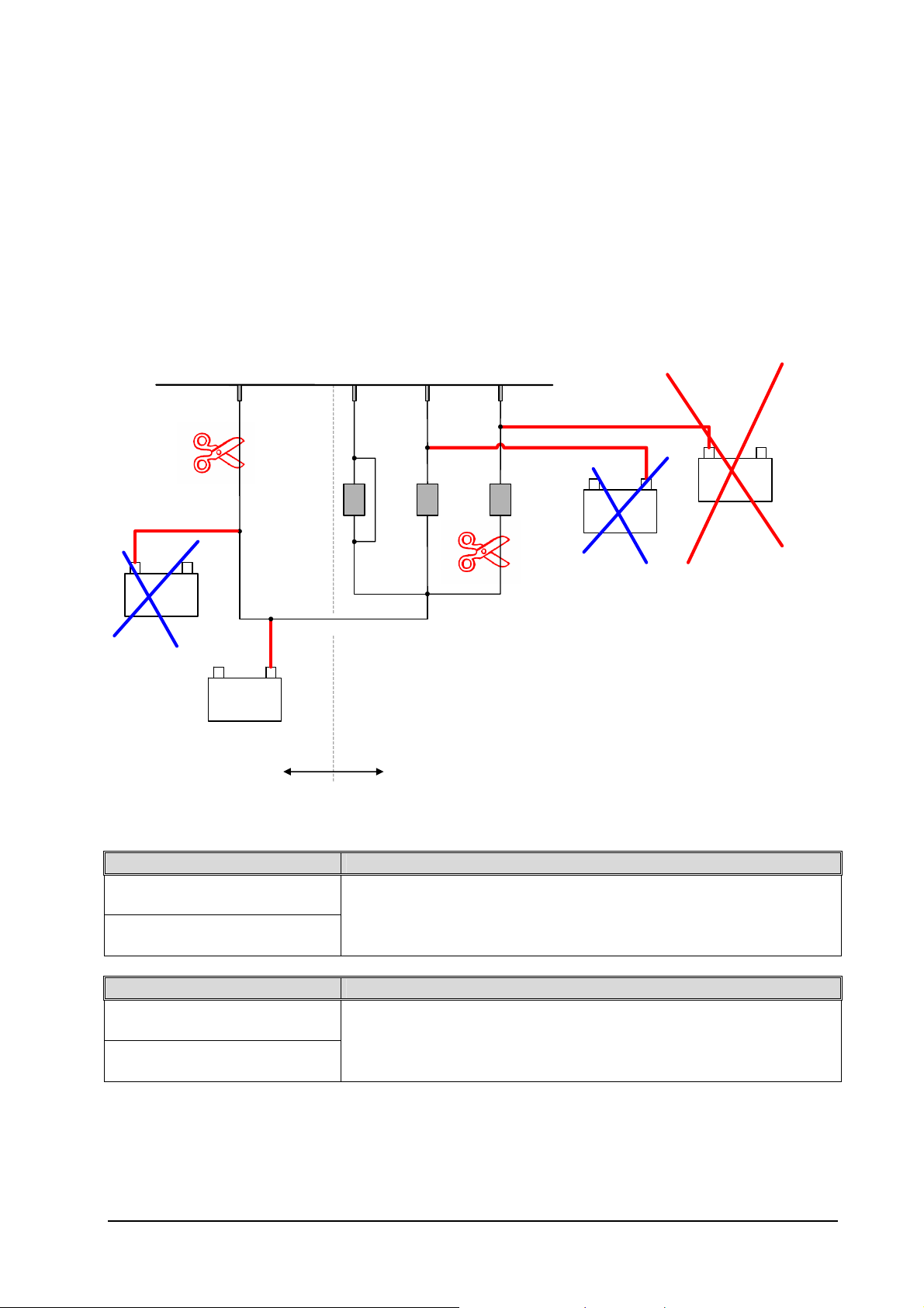
Engine protection: gas injection
Gas injector actuation of engine control
Bank supply
Ub short-circuit
+ -
B a ttery
no detection
bank-selective detection
+ -
B atte ry
S h ort- circu it to earth
L. probe switch 1
Break in wiring
L. probe switch 2
Interturn fault
L. probe switch 3
S h ort- circu it to earth
Title: Diagnosis of gas injeciton (Cyl. 1-6),
Ub sho rt-circu it, sh ort-c ircuit to e arth , b re a k in wirin g
File:
Date of last change : 2001-08-22
valve-selective detection
Ub short-circuit
Break in wiring
kd_hwd_eingasung_übersicht.vsd
+ -
B atte ry
no detection
+ -
B atte ry
- no detection
- C ontrol unit de struction
Fault on Gas Injector Measures
Æ Break in wiring
Æ Interturn fault
- Torque reduction: 20 % per failed "injector pair"
- The actuation of the corresponding "injector pair" is deactivated
- Ignition remains completely switched on (all cylinders)
- Lambda control remains switched on
Fault on Bank Supply Measures
Æ Break in wiring
Æ Short circuit to ground
- Torque reduction: 20 % per failed "injector pair"
- The actuation of the corresponding "injector pairs" is deactivated
- Ignition remains completely switched on (all cylinders)
- Lambda control remains switched on
Status September 2003 (EvoBus-Service / AFT) Page: 22 of 83

Functional Description of EGM
y
y
_____________________________________________________________________
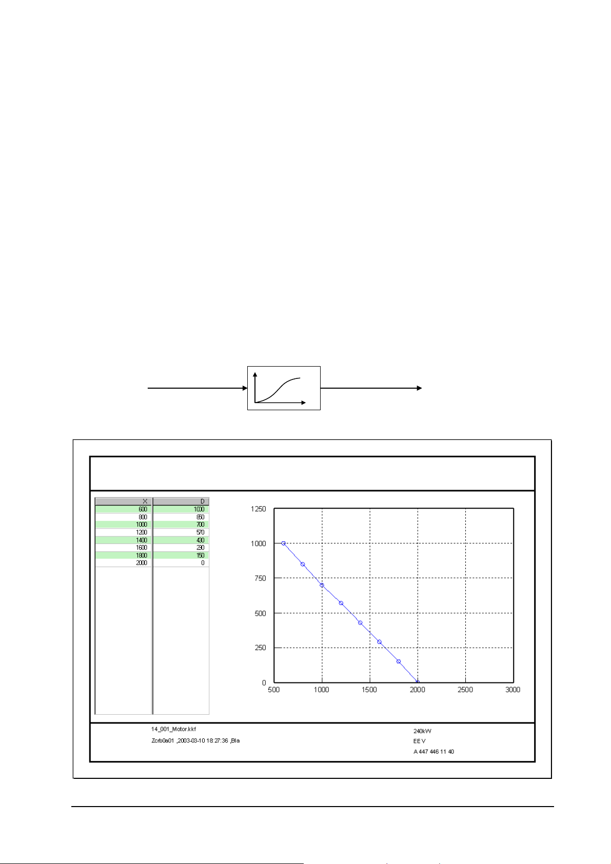
2.2.1.9 Engine protection: ignition
From the software version 13A, the EGM engine control unit is capable of detecting breaks in wiring on
the primary side and interturn faults on the actuation cables of the ignition modules. In the case of a
fault, the corresponding fault codes are stored in the fault memory and corresponding emergency running
measures are initiated. The EGM engine control unit is capable of compensating the failure of up to three
cylinders; if an additional cylinder fails, the engine is switched off.
Engine protection: ignition
Actuation of engine control
Short-circuit to earth
+ -
Batter
Ub short-circuit
wiring
Break in
+ -
Batter
4 3
Ignition module
5
Title: Diagnosis of gas injeciton (Cyl. 1-6),
Ub short-circuit, short-circuit to earth, break in wiring
File: kd_hwd_zuendung_Fehlerdarstellung.vsd
Kl.
Date of last change: 2001-08-22
GND
As in the case of defective actuation of the ignition modules, a failure of the ignition on the corresponding
cylinder should be assumed, the engine availability is greatly reduced if a fault occurs.
If a fault occurs:
- the torque specification of the driver is ignored (limited to zero),
- an increased engine idling speed of approx. 900 rpm is set and
- the lambda control is switched off.
Note:
• Faults in the secondary side of the ignition system can NOT currently be directly detected by the
EGM engine control unit!!
• An indirect detection is possible from software version 14A with the exhaust-gas temperature sensor
following the catalyst. The conditions is that the catalyst has reached the operating temperature.
Status September 2003 (EvoBus-Service / AFT) Page: 23 of 83
Functional Description of EGM
_____________________________________________________________________
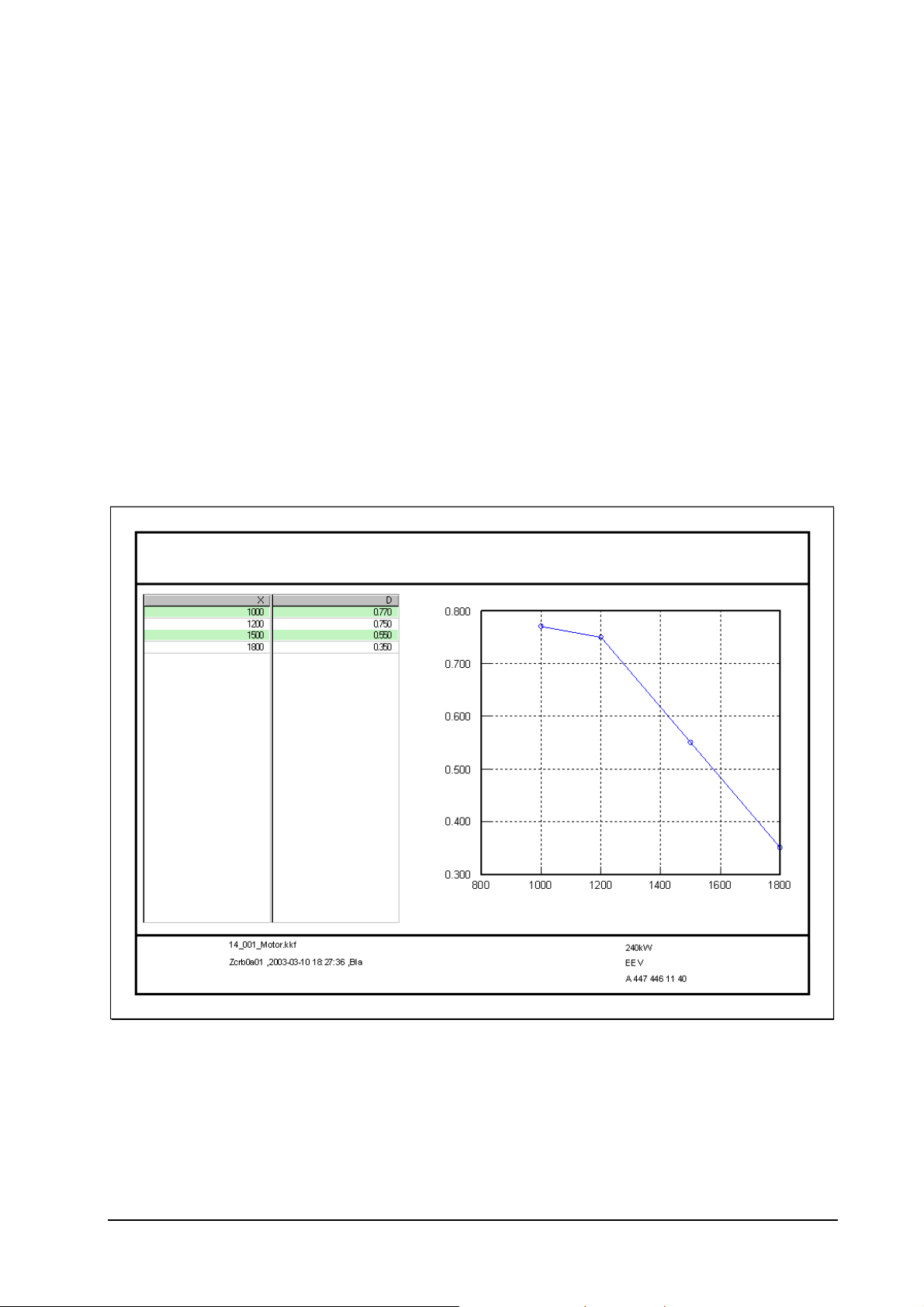
2.2.1.10 Engine protection: oil pressure
With the engine protection function oil pressure it is currently possible to display a two-stage warning
concept. The engine protection function is calculated every 10 ms in the engine-on mode with insufficient
oil pressure, and in the other states ("Engine stopped", Start") the function is reset.
• Blocking time after Start operation
As the oil pressure may at first be built up with a delay following engine starting, the oil pressure
engine protection function can be blocked for a period of 10 seconds after start operation (transition
from engine state "Start" to "Normal operation"). The function remains reset, i.e. no oil pressure
warnings are output.
• Oil pressure warnings
Depending on the speed, two characteristic curves are available with which the respective minimum
permissible oil pressure can be described.
If the oil pressure drops below the threshold value from the pre-warning characteristic curve, the oil
pressure pre-warning is transmitted. If the oil pressure drops below the threshold value from the
warning characteristic curve, the oil pressure pre-warning is cancelled and the oil-pressure warning is
transmitted via the CAN.
Engine protection: oil pressure pre-warning threshold
MTS - Oil-pressure pre-warning threshold
Oil pressure threshold [bar] = f(Speed [rpm])
P oil MIN
Speed
Status September 2003 (EvoBus-Service / AFT) Page: 24 of 83
_____________________________________________________________________
Engine protection: oil-pressure warning threshold
MTS - Oil-pressure warning threshold
Oil pressure threshold [bar] = f(Speed [rpm])
P oil MIN
Functional Description of EGM
Speed
2.2.1.11 Engine protection: overspeed
To protect the engine against operation at an impermissibly high speed ("overspeed"), an overspeed
protection function is implemented in the control unit. This is calculated at intervals of 10 ms regardless
of the engine state. If the engine speed exceeds the threshold of 2,360 rpm for soft speed limitation (DRB
soft), then the overspeed protection function activates the soft speed limitation in the first step. In the
process the throttle valve is moved into the position 2° DK. If the engine speed exceeds the threshold of
2,400 rpm for hard speed limitation (DRB hard), then the overspeed protection function also switches off
the gas injection in the second step until the condition for hard speed limitation is no longer met.
2.2.1.12 Engine protection: exhaust-gas temperature
To protect the catalyst and adjacent components from excessively high temperatures ("Cat fire"), the
exhaust-gas temperature after the catalyst is monitored. Due to malfunctions in the ignition of gas
injection, the catalyst may be flooded with unburned gas. If the catalyst is already at operating
temperature, extremely high temperatures result in the catalyst due to the increased transfer of gas and
residual air. If the exhaust-gas temperature exceeds 650 °C, a warning is set and the available engine
torque is greatly reduced. From 700 °C the red warning lamp and the warning buzzer are actuated and
the vehicle should be stopped as quickly as possible and the engine switched off.
Status September 2003 (EvoBus-Service / AFT) Page: 25 of 83
 Loading...