


TM 55-2420-224-14
TECHNICAL MANUAL
TRANSPORTABILITY GUIDANCE
SMALL
EMPLACEMENT EXCAVATOR (SEE)
(NSN 2420-01-160-2754)
HIGH MOBILITY ENTRENCHER (HME)
(NSN 2420-01-228-8610)
HIGH MOBILITY MATERIAL HANDLER (HMMH)
(NSN 2420-01-205-8636)
Approved for public release; distribution is unlimited
HEADQUARTERS, DEPARTMENT OF THE ARMY
18 FEBRUARY 1990

T
ECHNICAL MANUAL
N
O. 55-2420-224-14
TM 55-2420-224-14
HEADQUARTERS
DEPARTMENT OF THE ARMY
ASHINGTON, DC 18 February 1990
W
TRANSPORTABILITY GUIDANCE
SMALL EMPLACEMENT EXCAVATOR
(NSN 2420-01-160-2754)
HIGH MOBILITY ENTRENCHER (HME)
(NSN 2420-01-228-8610)
HIGH MOBILITY MATERIAL HANDLER (HMMH)
(NSN 2420-01-205-8636)
C
HAPTER
C
HAPTER
S
ECTION
C
HAPTER
C
HAPTER
C
HAPTER
S
ECTION
C
HAPTER
S
ECTION
I.
INTRODUCTION
Purpose and Scope
Reporting of Recommendations and Comments . . . . . . . . . . . . . . . . . . . . . . . . . . . . . . . . . . . . . . . . . . .
Definitions of Warnings, Cautions, and Notes . . . . . . . . . . . . . . . . . . . . . . . . . . . . . . . . . . . . . . . . . . . . .
2.
TRANSPORTABILITY DATA
I.
GENERAL
Scope . . . . . . . . . . . . . . . . . . . . . . . . . . . . . . . . . . . . . . . . . . . . . . . . . . . . . . . . . . . . . . . . . . . . . . . . . . . . .
Description . . . . . . . . . . . . . . . . . . . . . . . . . . . . . . . . . . . . . . . . . . . . . . . . . . . . . . . . . . . . . . . . . . . . . . . . . . . .
Transportability Drawings . . . . . . . . . . . . . . . . . . . . . . . . . . . . . . . . . . . . . . . . . . . . . . . . . . . . . . . . . . . . . .
II.
CHARACTERISTICS AND RELATED DATA
General Transportability Characteristics . . . . . . . . . . . . . . . . . . . . . . . . . . . . . . . . . . . . . . . . . . . . . . . . .
Reduced Configuration . . . . . . . . . . . . . . . . . . . . . . . . . . . . . . . . . . . . . . . . . . . . . . . . . . . . . . . . . . . . . . . . . .
Unusual Characteristics . . . . . . . . . . . . . . . . . . . . . . . . . . . . . . . . . . . . . . . . . . . . . . . . . . . . . . . . . . . . . . . . .
Hazardous and Dangerous Characteristics. . . . . . . . . . . . . . . . . . . . . . . . . . . . . . . . . . . . . . . . . . . . . . . .
3.
SAFETY
General . . . . . . . . . . . . . . . . . . . . . . . . . . . . . . . . . . . . . . . . . . . . . . . . . . . . . . . . . . . . . . . . . . . . . . . . . . . . . . . .
Specific Safety Requirements . . . . . . . . . . . . . . . . . . . . . . . . . . . . . . . . . . . . . . . . . . . . . . . . . . . . . . . . . . . .
4.
AIR TRANSPORTABILITY GUIDANCE
Scope . . . . . . . . . . . . . . . . . . . . . . . . . . . . . . . . . . . . . . . . . . . . . . . . . . . . . . . . . . . . . . . . . . . . . . . . . . . . . . . . . .
Maximum Use of Aircraft Capacity . . . . . . . . . . . . . . . . . . . . . . . . . . . . . . . . . . . . . . . . . . . . . . . . . . . . . .
Applicability . . . . . . . . . . . . . . . . . . . . . . . . . . . . . . . . . . . . . . . . . . . . . . . . . . . . . . . . . . . . . . . . . . . . . . . . . .
Safety . . . . . . . . . . . . . . . . . . . . . . . . . . . . . . . . . . . . . . . . . . . . . . . . . . . . . . . . . . . . . . . . . . . . . . . . . . . . . . . . . .
Reparation of Equipment . . . . . . . . . . . . . . . . . . . . . . . . . . . . . . . . . . . . . . . . . . . . . . . . . . . . . . . . . . . . . . .
Transport by US Aircraft . . . . . . . . . . . . . . . . . . . . . . . . . . . . . . . . . . . . . . . . . . . . . . . . . . . . . . . . . . . . . .
Transport by LVAD and LAPE . . . . . . . . . . . . . . . . . . . . . . . . . . . . . . . . . . . . . . . . . . . . . . . . . . . . . . . . . .
Helicopter Transport . . . . . . . . . . . . . . . . . . . . . . . . . . . . . . . . . . . . . . . . . . . . . . . . . . . . . . . . . . . . . . . . . . . .
5.
HIGHWAY TRANSPORTABILITY GUIDANCE
I.
GENERAL
Scope . . . . . . . . . . . . . . . . . . . . . . . . . . . . . . . . . . . . . . . . . . . . . . . . . . . . . . . . . . . . . . . . . . . . . . . . . . . . . .
Safety
II.
III.
6.
I.
II.
. . . . . . . . . . . . . . . . . . . . . . . . . . . . . . . . . . . . . . . . . . . . . . . . . . . . . . . . . . . . . . . .
SELF-PROPELLED MOVEMENT
General . . . . . . . . . . . . . . . . . . . . . . . .
Preparation of the SEE, HME, and HMMH . . . . . . . . . . . . . . . . . . . . . . . . . . . . . . . . . . . . . . . . . . . .
TRANSPORT BY TRACTOR-TRAILER OR SEMITRAILER
General
Transport on M345 Trailer . . . . . . . . . . . . . . . . . . . . . . . . . . . . . . . . . . . . . . . . . . . . . . . . . . . . . . . . . . . . . .
MARINE AND TERMINAL TRANSPORTABILITY GUIDANCE
GENERAL
Scope . . . . . . . . . . . . .
Safety
Water Shipment . . . . . . . . . . . . . . . . . . . . . . . . . . . . . . . . . . . . . . . . . . . . . . . . . . . . . . . . . . . . . . . . . . . . . . . .
LOADING AND SECURING
General Rules . . . . . . . . . . . . . . . . . . . . . . . . . . . . . . . . . . . . . . . . . . . . . . . . . . . . . . . . . . . . . . . . . . . . . . . . . .
General Cargo and Barge-Type (LASH and SEABEE) Ships . . . . . . . . . . . . . . . . . . . . . . . . . . . . . . .
Roll-on/Roll-off (RORO), Seatrain, Landing, and Attack Cargo Ships . . . . . . . . . . . . . . . . .
. . . . . . . . . . . . . . . . . . . . . . . . . . . . . . . . . . . . . . . . . . . . . . . . . . . . . . . . . . . . . . . . . . . . . . . . . . . . . .
. . . . . . . . . . . . . . . . . . . . . . . . . . . . . . . . . . . . . . . . . . . . . . . . . . . . . . . . . . . . . . .
. . . . . . . . . . . . . . . . . . . . . . . . . . . . . . . . . . . . . . . . . . . . . . . . . . . . . . . . . . . . . . . . . . . . . .
. . . . . . . . . . . . . . . . . . . . . . . . . . . . . . . . . . . . . . . . . . . . . . . . . . . . . .
. . . . . . . . . . . . . . . . . . . . . . . . . . . . . . . . . . . . . . . . . . . . . . . . . . . . . . . . . . . . . . .
Paragraph
1-1
1-2
1-3
2-1
2-2
2-3
2-4
2-5
2-6
2-7
3-1
3-2
4-1
4-2
4-3
4-4
4-5
4-6
4-7
4-8
5-1
5-2
5-3
5-4
5-5
5-6
6-1
6-2
6-3
6-4
6-5
6-6
Page
1-1
1-1
1-1
2-1
2-1
2-1
2-7
2-6
2-6
2-6
3-1
3-1
4-1
4-1
4-1
4-1
4-1
4-1
4-2
4-2
5-1
5-1
5-1
5-1
5-1
5-1
6-1
6-1
6-1
6-1
6-1
6-5
i

TM 55-2420-224-14
CHAPTER 7.
ECTION I.
S
II.
III.
APPENDIX A.
Figure
B.
2-1
2-2
2-3
2-4
2-5
4-1
4-2
4-3
4-4
4-5
4-6
4-7
4-8
4-9
5-1
6-1
6-2
6-3
6-4
7-1
7-2
7-3
7-4
7-5
Paragraph
RAIL TRANSPORTABILITY GUIDANCE
GENERAL
Scope . . . . . . . . . . . . . . . . . . . . . . . . . . . . . . . . . . . . . . . . . . . . . . . . . . . . . . . . . . . . . . . . . . . . . . . . . . . . . . . . . . . . . . . .
Maximum Use of Railcard . . . . . . . . . . . . . . . . . . . . . . . . . . . . . . . . . . . . . . . . . . . . . . . . . . . . . . . . . . . . . .
TRANSPORT ON CONUS RAILWAYS
General . . . . . . . . . . . . . . . . . . . . . . . . . . . . . . . . . . . . . . . . . . . . . . . . . . . . .
Preparation . . . . . . . . . . . . . . . . . . . . . . . . . . . . . . . . . . . . . . . . . . . . . . . . . . . . . . . . . . . . . . . . . . . .
Loading the SEE or Variants on a General-Purpose Flatcar . . . . . . . . . . . . . . . . . . . . . . . . . . . . . . .
Loading the SEE or Variants on Special-Purpose Flatcars . . . . . . . . . . . . . . . . . . . . . . . . . . . . . . . . .
TRANSPORT ON FOREIGN RAILWAYS
General . . . . . . . . . . . . . . . . . . . . . . . . . . . . . . . . . . . . . . . . . . . . . . . . . . . . . . . . . . . . . . . . . . . . . .
Transport on Foreign-Service Flatcars . . . . . . . . . . . . . . . . . . . . . . . . . . . . . . . . . . . . . . . . . . . . . . . . . . . .
CONVERSION TABLES . . . . . . . . . . . . . . . . . . . . . . . . . . . . . . . . . . . . . . . . . . . . . . . . . . . . . . . . . .
REFERENCES . . . . . . . . . . . . . . . . . . . . . . . . . . . . . . . . . . . . . . . . . . . . . . . . . . . . . . . . . . . . . . .
LIST OF ILLUSTRATIONS
Small emplacement excavator (SEE) . . . . . . . . . . . . . . . . . . . . . . . . . . . . . . . . . . . . . . . . . . . .
High mobility material handler (HMMH). . . . . . . . . . . . . . . . . . . . . . . . . . . . . .
Transportability drawing, left-side and rear views of the small emplacement excavator . . . . . . . . . . . . . . . . . .
Transportability drawing, left-side and rear views of the high mobility entrenched . . . . . . . . . . . . . . . . . . . . . .
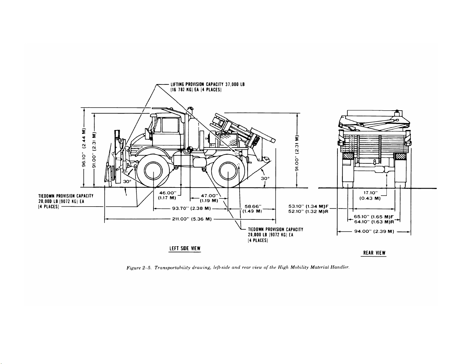
Transportability drawing, left-side and rear views of the high mobility material handler . . . . . . . . . . . . . . . .
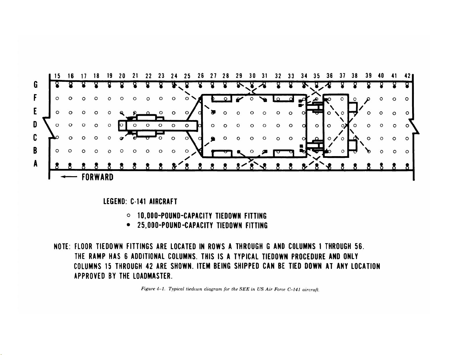
Typical tiedown diagram for the SEE in US Air Force C-141 aircraft . . . . . . . . . . . . . . . . . . . . . . . . . . . . . . . . . .
Typical tiedown diagram for the HME in US Air Force C-130 aircraft . . . . . . . . . . . . . . . . . . . . . . . . . . . . . . . . .
Typical tiedown diagram for the HMMH in US Air Force C-5 aircraft . . . . . . . . . . . . . . . . . . . . . . . . . . . . . . . . .
SEE being lifted with single-hook method by CH-47 helicopter. . . . . . . . . . . . . . . . . . . . . . . . . . . . . . . . . . . . . . . .
SEE being lifted with dual-hook method by CH-47 helicopter. . . . . . . . . . . . . . . . . . . . . . . . . . . . . . . . . . . . . . . . .
SEE being lifted by CH-54 helicopter . . . . . . . . . . . . . . . . . . . . . . . . . . . . . . . . . . . . . . . . . . . . . . . . . . . . . . . . . . . . . . . .
Front sling legs preparation on SEE (front view) . . . . . . . . . . . . . . . . . . . . . . . . . . . . . . . . . . . . . . . . . . . . . . . . . . . . . .
Right rear sling leg preparation on SEE (rear view) . . . . . . . . . . . . . . . . . . . . . . . . . . . . . . . . . . . . . . . . . . . . . . . . . . .
Left rear sling leg preparation on SEE (rear view) . . . . . . . . . . . . . . . . . . . . . . . . . . . . . . . . . . . . . . . . . . . . . . . . . . . .
Typical tiedown diagram for the SEE, HME, and HMMH on an M345 trailer (side view) . . . . . . . . . . . . . . . .
Typical four-leg sling-lifting diagram for the SEE, HME, and HMMH with wire rope . . . . . . . . . . . . . . . . . . .
Typical blocking and tiedown of the SEE, HME, and HMMH in general-cargo and barge-type vessels . . . .
Typical loading of the SEE, HME, and HMMH on a LASH lighter with wire rope, cable clamps,
turnbuckles, and blocking . . . . . . . . . . . . . . . . . . . . . . . . . . . . . . . . . . . . . . . . . . . . . . . . . . . . . . .
Typical tiedown of the SEE, HME, and HMMH on a RORO vessel . . . . . . . . . . . . . . . . . . . . . . . . . . . . . . . . . . . . .
Typical blocking and tiedown for the SEE and HME on a CONUS general-purpose flatcar (side view) . . . .
Typical blocking and tiedown for the SEE and HME on a CONUS general-purpose flatcar (rear view) . . . .
Typical blocking and tiedown detail diagram . . . . . . . . . . . . . . . . . . . . . . . . . . . . . . . . . . . . . . . . . . . . . . . . . . . . . . . . .
Typical tiedown for the SEE and variants on a CONUS conventional wood-deck, chain-tiedown flatcar
(side view) . . . . . . . . . . . . . . . . . . . . . . . . . . . . . . . . . . . . . . . . . . .
Typical tiedown for the SEE and variants on a CONUS conventional wood-deck, chain-tiedown flatcar
(rear view) . . . . . . . . . . . . . . . . . . . . . . . . . . . . . . . . . . . . . . . . . . . . . . . . . . . .
7-1
7-2
7-3
7-4
7-5
7-6
7-7
7-8
Page
7-1
7-1
7-1
7-1
7-1
7-1
7-7
7-7
A-1
B-1
Page
2-2
2-3
2-4
2-5
2-6
4-3
4-4
4-5
4-6
4-7
4-8
4-9
4-10
4-12
5-2
6-2
6-3
6-6
6-7
7-2
7-3
7-4
7-8
7-9
LIST OF TABLES
Table
5-1
5-2
6-1
6-2
7-1
7-2
7-3
ii
Bill of Materials for Blocking and Tiedown of the SEE, HME, and HMMH on the M345 Trailer (Fig 5-1)
Application of Materials for Blocking and Tiedown of the SEE, HME, and HMMH on the M345 Trailer
(Fig 5-1) . . . . . . . . . . . . . . . . . . . . . . . . . . . . . . . . . . . . . . . . . . . . . . . .
Bill of Materials for Blocking and Tiedown of a Typical SEE, HME, and HMMH in a General-Cargo
Vessel (Fig 6-2) . . . . . . . . . . . . . . . . . . . . . . . . . . . . . . . . . . . . . . . . . . . . . . . . . . . . . . . . . . .
Application of Materials for Blocking and Tiedown
General-Cargo Vessel (Fig 6-2) . . . . . . . . . . . . . . . . . . . . . . . . . . . . . . . . . . . . . . . . . . . . . . . . . . . . . . . . . .
Bill of Materials for Blocking and Tiedown of the SEE and HME on a CONUS General-Purpose Flatcar
(Figs 7-1 and 7-2) . . . . . . . . . . . . . . . . . . . . . . . . . . . . . . . . . . . . . . . . . . . . . . . . . .
Application of Materials for Blocking and Tiedown of the SEE and HME on a CONUS General-Purpose
Flatcar (Figs 7-1 and 7-2) . . . . . . . . . . . . . . . . . . . . . . . . . . . . . . . . . . . . . . . .
Application of Chain Tiedowns for Securing the HMMH on HTTX or Similar Type of Flatcars (Figs 7-4
and 7-5) . . . . . . . . . . . . . . . . . . . . . . . . . . . . . . . . . . . . . . . . . . . . . . . . . . . . . . . . . . . . . .
of a Typical SEE, HME, and HMMH in a
Page
5-3
5-3
6-4
6-4
7-5
7-5
7-6

CHAPTER 1
INTRODUCTION
TM 55-2420-224-14
1-1. Purpose and Scope
This manual provides transportability guidance for
logistical handling and movement of the small
emplacement excavator (SEE), high mobility entrencher (HME), and high mobility material handler (HMMH). It contains information considered
appropriate for safe transport of the SEE and its
variants. The information includes significant
technical and physical characteristics, as well as
safety considerations,
movement by the various transport modes. Where
considered necessary, metric equivalents appear in
parentheses following the dimensions or other
measurements. This manual is for transportation
officers and other personnel responsible for moving
the SEE, HME, and HMMH, or for providing
transport services.
required for worldwide
1-2. Reporting of Recommendations
and Comments
Users of this manual are encouraged to submit
comments and to recommend changes for its im-
provement. Comments and recommendations
should be prepared on DA Form 2028 (Recommended Changes to DA Publications and Blank
Forms) and forwarded to Commander, Military
Traffic Management Command Transportation Engineering Agency, ATTN: MTTE-TRS, PO Box
6276, Newport News, VA 23606–0276. Electrically
transmitted messages should be addressed
MTMCTEA FT EUSTIS VA//MTTE-TRS//.
1-3. Definitions of Warnings,
to CDR
Cau-
tions, and Notes
Throughout this manual, warnings, cautions, and
notes emphasize important or critical guidance.
They are used for the following conditions:
a. Warning. Instructions that, if not followed,
could result in injury to or death of personnel.
b. Caution. Instructions that, if not strictly observed, could result in damage to or destruction of
equipment.
c. Note. An operating procedure or condition
that must be emphasized.
1-1

CHAPTER 2
TRANSPORTABILITY DATA
Section I. GENERAL
TM 55-2420-224-14
2-1. Scope
This chapter provides transportability characteris-
tics of the SEE, HME, and HMMH.
2-2. Description
The SEE, HME, and HMMH are commercial items
of construction equipment. The tractor portion of
the equipment is a light truck chassis equipped
with a diesel engine, multispeed range transmission, and offroad flotation tires. The tractor has a
45-mile-per-hour (72-km/h) highway convoy speed
as well as a full drive rough-terrain capability.
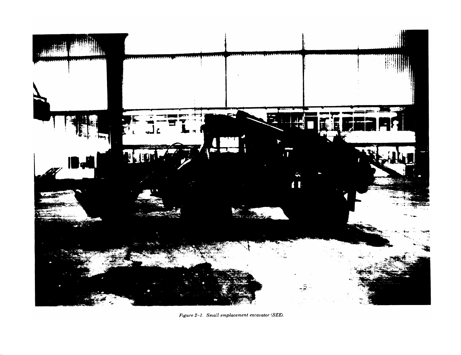
a. The SEE tractor configuration consists of the
basic tractor with a 3/4-cubic-yard-capacity front
end loader and rear-mounted backhoe. The backhoe has a 7-cubic-foot-capacity bucket, as shown in
figure 2-1.
b. The HME variant consists of the same basic
tractor as the SEE, but with a dozer blade (85
inches wide and 32 inches high) on the front end
and an entrencher on the rear. No photograph is
available at this time.
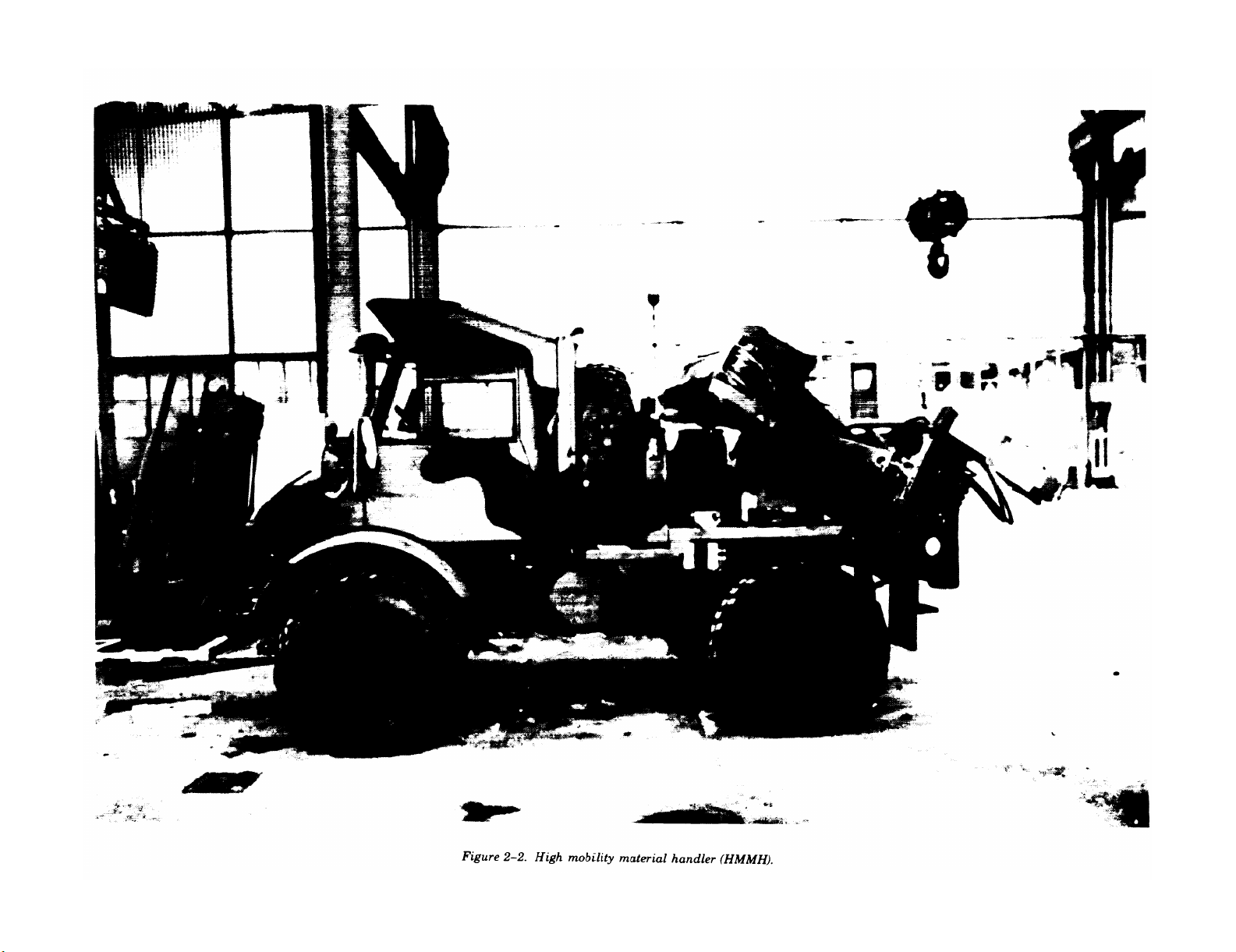
c. The HMMH variant consists of the same
basic tractor as the SEE, but with a 4,000-pound
(1814-kg)-capacity forklift mounted to the front
and a 6,000 pound (2722-kg)-capacity crane at-
tached to the rear of the vehicle, as shown in
figure 2-2.
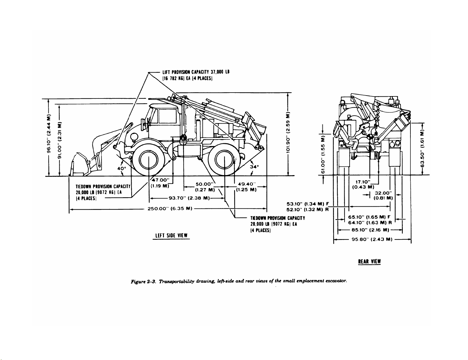
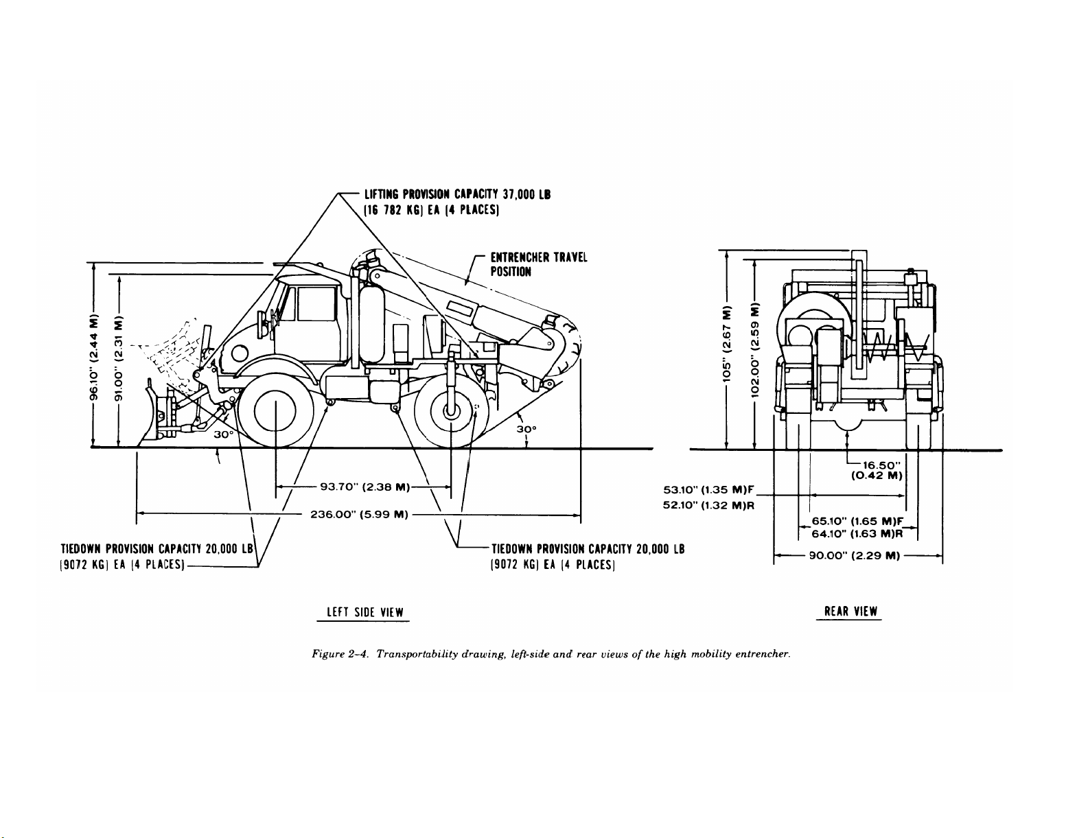
2-3. Transportability Drawings
Figures 2-3 through 2-5 are detailed side- and
rear-view transportability drawings of the SEE,
HME, and HMMH with dimensions, tiedown and
lifting provisions, and load-rating capacities.
2-1
2-2
TM 55-2420-224-14
Figure 2-1.
TM 55-2420-224-14
2-3
Figure 2-2.
2-4
TM 55-2420-224-14
Figure 2-3.
2-5
TM 55-2420-224-14
Figure 2-4.
2-6
TM 55-2420-224-14
Figure 2-5.

TM 55-2420-224-14
Section II. CHARACTERISTICS AND RELATED DATA
2-4. General Transportability Characteristics
Data contained here apply to the model numbers or national stock numbers (NSN) shown. Changes in
model numbers or NSN may affect the loadability of the item as related to the guidance in this manual.
a. Small Emplacement Excavator.
National stock number . . . . . . . . . . . . . . . . . . . . . . . . . . . . . . . . . . . . . . . . . . . . . . . . . . . . . . . . . . . . . . . . . . . . . .
Line item number . . . . . . . . . . . . . . . . . . . . . . . . . . . . . . . . . . . . . . . . . . . . . . . . . . . . . . . . . . . . . . . . . . . . . . . . . . . . . .
Length:
Operational configuration (maximum) . . . . . . . . . . . . . . . . . . . . . . . . . . . . . . . . . . . . . . . . . . . . . . . . . . . . . . . .
Travel configuration . . . . . . . . . . . . . . . . . . . . . . . . . . . . . . . . . . . . . . . . . . . . . . . . . . . . . . . . . . . . . . . . . . . . . . . .
Width:
Operational configuration (maximum) . . . . . . . . . . . . . . . . . . . . . . . . . . . . . . . . . . . . . . . . . . . . . . . . . . . . . . . .
Travel configuration . . . . . . . . . . . . . . . . . . . . . . . . . . . . . . . . . . . . . . . . . . . . . . . . . . . . . . . . . . . . . . . . . . . . . . .
Height:
Operational configuration (maximum) . . . . . . . . . . . . . . . . . . . . . . . . . . . . . . . . . . . . . . . . . . . . . . . . . . . . . . . .
Travel configuration . . . . . . . . . . . . . . . . . . . . . . . . . . . . . . . . . . . . . . . . . . . . . . . . . . . . . . . . . . . . . . . . . . . . . . .
Area:
Operational configuration (maximum) . . . . . . . . . . . . . . . . . . . . . . . . . . . . . . . . . . . . . . . . . . . . . . . . . . . . . . . .
Travel configuration . . . . . . . . . . . . . . .
. . . . . . . . . . . . . . . . . . . . . . . . . . . . . . . . . . . . . . . . . . . . . . . . . . . . . . . .
Volume:
Operational configuration (maximum)
Travel configuration . . . . . . . . . . . . . . .
. . . . . . . . . . . . . . . . . . . . . . . . . . . . . . . . . . . . . . . . . . . . . . . . . . . . . . . .
. . . . . . . . . . . . . . . . . . . . . . . . . . . . . . . . . . . . . . . . . . . . . . . . . . . . . . . .
Weight:
Front axle
. . . . . . . . . . . . . . . . . . . . . . . . . . . . . . . . . . . . . . . . . . . . . . . . . . . . . . . . . . . . . . . .
Rear axle . . . . . . . . . . . . . . . . . . . . . . . . . . . . . . . . . . . . . . . . . . . . . . . . . . . . . . . . . . . . . . . . . . . . . . . . . . . . . . . . . .
Total weight . . . . . . . . . . . . . . . . . . . . . . . . . . . . . . . . . . . . . . . . . . . . . . . . . . . . . . . . . . . . . . . . . . . . . . . . . . . . . . . .
Tires:
Number/size . . . . . . . . . . . . . . . . . . . . . . . . . . . . . . . . . . . . . . . . . . . . . . . . . . . . . . . . . . . . . . . . . . . . . . . . . . . . . . . .
Pressure:
Front . . . . . . . . . . . . . . . . . . . . . . . . . . . . . . . . . . . . . . . . . . . . . . . . . . . . . . . . . . . . . . . . . . . . . . . . . . . . . . . . . . . . . .
Rear . . . . . . . . . . . . . . . . . . . . . . . . . . . . . . . . . . . . . . . . . . . . . . . . . . . . . . . . . . . . . . . . . . . . . . . . . . . . . . . . . . . . . . .
Contact area:
Front . . . . . . . . . . . . . . . . . . . . . . . . . . . . . . . . . . . . . . . . . . . . . . . . . . . . . . . . . . . . . . . . . . . . . . . . . . . . . . . . . . . . . .
Rear . . . . . . . . . . . . . . . . . . . . . . . . . . . . . . . . . . . . . . . . . . . . . . . . . . . . . . . . . . . . . . . . . . . . . . . . . . . . . . . . . . . . . . .
Speed/range:
Maximum speed . . . . . . . . . . . . . . . . . . . . . . . . . . . . . . . . . . . . . . . . . . . . . . . . . . . . . . . . . . . . . . . . . . . . . . . . . . . .
Operational range . . . . . . . . . . . . . . . . . . . . . . . . . . . . . . . . . . . . . . . . . . . . . . . . . . . . . . . . . . . . . . . . . . . . . . . . . .
Ground clearances–differential . . . . . . . . . . . . . . . . . . . . . . . . . . . . . . . . . . . . . . . . . . . . . . . . . . . . . . . . . . . . . .
b. High Mobility Entrenched.
National stock number. . . . . . . . . . . . . . . . . . . . . . . . . . . . . . . . . . . . . . . . . . . . . . . . . . . . . . . . . . . . . . . . . . . . .
Line item number . . . . . . . . . . . . . . . . . . . . . . . . . . . . . . . . . . . . . . . . . . . . . . . . . . . . . . . . . . . . . . . . . . . . . . . . . .
Length, travel configuration . . . . . . . . . . . . . . . . . . . . . . . . . . . . . . . . . . . . . . . . . . . . . . . . . . . . . . . . . . . . . . . . .
Width, travel configuration . . . . . . . . . . . . . . . . . . . . . . . . . . . . . . . . . . . . . . . . . . . . . . . . . . . . . . . . . . . . . . . . . .
Height, travel configuration . . . . . . . . . . . . . . . . . . . . . . . . . . . . . . . . . . . . . . . . . . . . . . . . . . . . . . . . . . . . . . . . .
Area, travel configuration.. . . . . . . . . . . . . . . . . . . . . . . . . . . . . . . . . . . . . . . . . . . . . . . . . . . . . . . . . . . . . . . . . .
Volume, travel configuration . . . . . . . . . . . . . . . . . . . . . . . . . . . . . . . . . . . . . . . . . . . . . . . . . . . . . . . . . . . . . . . .
Weight:
Front axle . . . . . . . . . . . . . . . . . . . . . . . . . . . . . . . . . . . . . . . . . . . . . . . . . . . . . . . . . . . . . . . . . . . . . . . . . . . . . . . . . . .
Rear axle . . . . . . . . . . . . . . . . . . . . . . . . . . . . . . . . . . . . . . . . . . . . . . . . . . . . . . . . . . . . . . . . . . . . . . . . . . . . . . . . . .
Total weight. . . . . . . . . . . . . . . . . . . . . . . . . . . . . . . . . . . . . . . . . . . . . . . . . . . . . . . . . . . . . . . . . . . . . . . . . . . . . . . .
Tires:
Number/size . . . . . . . . . . . . . . . . . . . . . . . . . . . . . . . . . . . . . . . . . . . . . . . . . . . . . . . . . . . . . . . . . . . . . . . . . . . . . . . .
Pressure:
Front . . . . . . . . . . . . . . . . . . . . . . . . . . . . . . . . . . . . . . . . . . . . . . . . . . . . . . . . . . . . . . . . . . . . . . . . . . . . . . . . . . . . . .
Rear . . . . . . . . . . . . . . . . . . . . . . . . . . . . . . . . . . . . . . . . . . . . . . . . . . . . . . . . . . . . . . . . . . . . . . . . . . . . . . . . . . . . . . .
2420-01-160-2754
T34437
340.2 in. (8.64 m)
250.0 in. (6.35 m)
95.8 in. (2.43 m)
95.8 in. (2.43 m)
96.1 in. (2.44m)
101.9 in. (2.59 m)
226.3 ft2 (21.05 m2)
166.3 ft2 (15.47 m2)
1,720.7 ft3 (48.73 m3)
1,412.3 ft3 (39.99 m3)
8,760 lb (3973 kg)
7,160 lb (3248 kg)
15,920 lb (7221 kg)
4 ea 12.5 x 20
50 psi (344.40 kpa)
45 psi (310.30 kpa)
2
89.9 in.
95.5 in.
(0.06 m2)
2
(0.06 m2)
45 mph (72.41 km/h)
10 hours
17.1 in. (0.43 m)
2420-01-228-8610
T34437
236.0 in. (5.99 m)
90.0 in. (2.29 m)
105.0 in. (2.67 m)
2
147.5 ft
1,290.6 ft
(13.71 m2)
3
(36.55 m3)
7,830 lb (3551 kg)
7,670 lb (3479 kg)
15,500 lb (7030 kg)
4 ea 12.5 x 20
55 psi (379.72 kpa)
55 psi (379.72 kpa)
2-7

TM 55-2420-224-14
Contact area:
Front . . . . . . . . . . . . . . . . . . . . . . . . . . . . . . . . . . . . . . . . . . . . . . . . . . . . . . . . . . . . . . . . . . . . . . . .
Rear . . . . . . . . . . . . . . . . . . . . . . . . . . . . . . . . . . . . . . . . . . . . . . . . . . . . . . . . . . . . . . . . . . . . . . .
Speed/range:
Maximum speed . . . . . . . . . . . . . . . . . . . . . . . . . . . . . . . . . . . . . . . . . . . . . . . . . . . . . . . . .
Operational range . . . . . . . . . . . . . . . . . . . . . . . . . . . . . . . . . . . . . . . . . . . . . . . . . . . . . . . . . . . . .
Ground clearances–differential. . . . . . . . . . . . . . . . . . . . . . . . . . . . . . . . . . . . . . . . . . . . . . . . . . . . . . . . . . . . . .
45 mph (72.41 km/h)
c. High Mobility Material Handler.
National stock number . . . . . . . . . . . . . . . . . . . . . . . . . . . . . . . . . . . . . . . . . . . . . . . . . . . . . . . . .
Line item number . . . . . . . . . . . . . . . . . . . . . . . . . . . . . . . . . . . . . . . . . . . . . . . . . . . . . . . . . . . . . . .
Length, travel configuration . . . . . . . . . . . . . . . . . . . . . . . . . . . . . . . . . . . . . . . . . . . . . . . . . . . . . . . . . . . . . . . . .
Width, travel configuration . . . . . . . . . . . . . . . . . . . . . . . . . . . . . . . . . . . . . . . . . . . . . . . . . . . . . . . . .
Height, travel configuration . . . . . . . . . . . . . . . . . . . . . . . . . . . . . . . . . . . . . . . . . . . . . . . . . . . . . . . .
Area, travel configuration . . . . . . . . . . . . . . . . . . . . . . . . . . . . . . . . . . . . . . . . . . . . . . . . . . . . . . . . . . . . .
Volume, travel configuration . . . . . . . . . . . . . . . . . . . . . . . . . . . . . . . . . . . . . . . . . . . . . . . . . . . . . . . . . . . . . . . .
Weight:
Front axle . . . . . . . . . . . . . . . . . . . . . . . . . . . . . . . . . . . . . . . . . . . . . . . . . . . . . . . . . . . . . . . . . . . . . . . . . . . . . . . . . . . . . . . . . . . . . . . . .
Rear axle . . . . . . . . . . . . . . . . . . . . . . . . . . . . . . . . . . . . . . . . . . . . . . . . . . . . . . . . . . . . . . . . . . . . . . . . . . . . . . . . . . . . . . . . .
Total weight . . . . . . . . . . . . . . . . . . . . . . . . . . . . . . . . . . . . . . . . . . . . . . . . . . . . . . . . . . . . . . . . . . . . .
Tires:
Number/size . . . . . . . . . . . . . . . . . . . . . . . . . . . . . . . . . . . . . . . . . . . . . . . . . . . . . . . . . . . . . . . . . . . . . . . . . . . . . . .
Pressure:
Front . . . . . . . . . . . . . . . . . . . . . . . . . . . . . . . . . . . . . . . . . . . . . . . . . . . . . . . . . . . . . . . . . . . . . . . . . . . . . . . . . . .
Rear . . . . . . . . . . . . . . . . . . . . . . . . . . . . . . . . . . . . . . . . . . . . . . . . . . . . . . . . . . . . . . . . . . . . . . . . . . . . . . . . . .
Contact area:
Front . . . . . . . . . . . . . . . . . . . . . . . . . . . . . . . . . . . . . . . . . . . . . . . . . . . . . . . . . . . . . . . . . . . . . . . . . . . . . . . . . . . . . . . . . . . . . .
Rear . . . . . . . . . . . . . . . . . . . . . . . . . . . . . . . . . . . . . . . . . . . . . . . . . . . . . . . . . . . . . . . . . . . . . . .
Speed/range:
Maximum speed . . . . . . . . . . . . . . . . . . . . . . . . . . . . . . . . . . . . . . . . . . . . . . . . . . . . . . . . . . . . . .
Operational range . . . . . . . . . . . . . . . . . . . . . . . . . . . . . . . . . . . . . . . . . . . .
Ground clearances–differential . . . . . . . . . . . . . . . . . . . . . . . . . . . . . . . . . . . . . . . . . . . . . . . . . . . . . . . . . . . . . .
137.7 ft
1,130.0 ft
45 mph (72.41 km/h)
77.9 in.2 (0.05 m2)
2
76.0 in.
2420-01-205-3636
211.0 in. (5.36 m)
8,018 lb (3637 kg)
7,632 lb (3462 kg)
15,650 lb (7099 kg)
55 psi (379.72 kpa)
55 psi (379.72 kpa)
79.5 in.
76.1 in.
(0.04 m2)
10 hours
16.5 in. (0.42 m)
Z90450
94.0 in. (2.39 m)
96.1 in. (2.44 m)
2
(12.80 m2)
3
(30.89 m3)
4 ea 12.5 x 20
2
(0.05 m2)
2
(0.04 m2)
10 hours
17.1 in. (0.43m)
2-5. Reduced Configuration
Lower cost shipping can be obtained by reducing
each SEE, HME, and HMMH to its minimum
dimensions for terminal handling and ocean transport. Both side mirrors are to be folded in, and the
rear-mounted attachment is placed in the travel
position.
2-6. Unusual Characteristics
These vehicles have no unusual characteristics
that would require special attention be given to
temperature,
atmospheric pressure, or humidity
variations during their exposure to normal transportation environments.
2-7. Hazardous and Dangerous Characteristics
Under usual circumstances, the SEE, HME, and
HMMH will not present any hazardous or dangerous characteristics during exposure to normal
transportation environments.
NOTE
Those regulations and/or transportation
procedures normally associated with vehicles containing diesel fuel apply.
2-8

CHAPTER 3
SAFETY
TM 55-2420-224-14
3-1. General
General safety considerations and precautions for
movement are as follows:
a. Check each vehicle to ensure that all loose
items are properly secured.
b. When backing a vehicle, ensure that no
personnel or obstacles are in danger of being hurt
or damaged by the vehicle.
WARNING
Fire extinguishers must be readily available during all loading and unloading
operations.
WARNING
When vehicle engine is operating, provide
proper ventilation during loading and unloading operations.
of carbon monoxide fumes could be fatal.
Prolonged inhalation
3-2. Specific Safety Requirements
Appropriate chapters of this manual contain pertinent safety requirements by individual mode.
3-1

TM 55-2420-224-14
CHAPTER 4
AIR TRANSPORTABILITY GUIDANCE
4-1. Scope
This chapter provides air transportability guidance
for movement of the SEE, HME, and HMMH. It
covers significant technical and physical characteristics and safety considerations. Also, it prescribes
the materials required to prepare, load, and un-
load the SEE, HME, and HMMH when transported in the C–130, C–141, and C–5 US Air Force
aircraft and the Boeing 747 Civil Reserve Air
Fleet (CRAF) aircraft.
4-2. Maximum Use of Aircraft Capacity
Additional cargo, including personnel within allowable load limits and restrictions prescribed by
pertinent safety regulations, may be transported
with these vehicles on US Air Force aircraft.
4-3. Applicability
a. US Air Force Aircraft. When prepared for
loading as described in paragraph 4-5, the SEE,
HME, and HMMH are transportable in C-130,
C-141, and C-5 aircraft.
b. Tiedown Devices.
HMMH will be tied down according to section IV
of applicable procedures in TO 1C-XXX–9.
c. Loadmaster. The loadmaster will ensure that
the loaded equipment is secured according to
restraint criteria outlined in TO 1C–XXX–9.
Air Force aircraft loads in this manual
are illustrated to a minimum restraint of
3 g forward, 1.5 g aft, 1.5 g lateral and 2
g vertical. (Reference 1C-XXX-9 and
MIL-STD-1791.)
The SEE, HME, and
NOTE
4-4. Safety
In addition to safety precautions
chapter 3, the following precautions
SEE, HME, and HMMH:
a. Ensure that the fuel tanks are
one-fourth or more than three-fourths full.
b. Check each vehicle carefully to ensure that
all loose items are properly secured.
c. Check each vehicle to ensure there are no
fluid leaks.
d. Check all tiedown provisions and attached
structural members for any damage.
e. Check tire pressure to ensure tires are at
recommended highway pressure.
contained in
apply for the
not less than
f. Check batteries to ensure they are protected
against short circuits and secured so that leakage
of acid cannot occur (reference TM 38–250, para
8-47a). Also, check the fuel tanks and hydraulic
systems to ensure they comply with TM 38–250.
WARNING
Fire extinguishers must be readily available during all loading and unloading.
WARNING
Provide proper ventilation during loading.
Prolonged inhalation of exhaust fumes
could be fatal.
WARNING
Do not allow the vehicle to exceed 3 miles
per hour (walking speed) inside the aircraft or on the loading ramps.
4-5. Preparation of Equipment
a. Fold both mirrors and secure them with rope
to the roll over protection structure (ROPS).
b. Secure rear attachments with 1/2-inch wire
rope (safety cable) and two clips, when shipped in
the travel position.
tight) around the ROPS (or tiedown provision as
directed) and rear attachment to restrain the
attachment in case the mechanical lock is not
engaged or fails.
Install wire rope taut (not
4-6. Transport by US Aircraft
a. The SEE, when shipped in C–130 and C–141
aircraft, will have the backhoe attachment in the
operational configuration. The SEE should be
backed into the C-130 and C-141 aircraft using
two qualified operators. One driver operates the
tractor and the other operates the backhoe, adjust-
ing height during loading and unloading opera-
tions. Each SEE requires two stacks of parking
shoring (2 x 6 inches x 4 feet, two per stack)
between the front end loader and the aircraft floor.
Also, place two stacks of shoring (2 x 6 inches x 4
feet, two per stack) under lowered bucket and
aircraft floor.
b. The HME and HMMH, when shipped in
C–130 and C–141 aircraft, must be in the travel
configuration.
(1) HME. Install 1/2-inch wire rope (safety
cable) through ROPS and over entrenched attach-
ment, forming a loop. Secure the loop by pulling
and installing the wire rope taut (not tight) with
two 1/2-inch clips. Each HME requires two stacks
4-1

TM 55-2420-224-14
of parking shoring (2 x 6 inches x 4 feet, two per
stack) between the front dozer blade and the
aircraft floor.
(2) HMMH. Install 1/2-inch wire rope (safety
cable) around top crane arm and through left
center tiedown provision on chassis, forming a
loop. Secure the loop by pulling the wire rope taut
(not tight) and installing two 1/2-inch clips. Repeat
same procedure for right side, except loop wire
rope through right provision on chassis. Each
HMMH requires two stacks of parking shoring (2
x 6 inches x 5 feet, two per stack) between the
front forklift tines and the aircraft floor. Also the
rear outriggers are to be secured with 1/2-inch
wire rope (safety cable) looped around each outrigger and secured with two 1/2-inch clips.
c. The C–5 aircraft can transport the SEE,
HME, and HMMH in the travel configurations.
(1) SEE. Install 1/2-inch wire rope (safety
cable) taut (not tight) around the ROPS and the
backhoe attachment and secure with two 1/2-inch
clips. Also, install on right outrigger a 1/2-inch
wire rope (safety cable) taut (not tight) through the
bucket tiedown provisional and around outriggers.
Repeat procedures for left outrigger. Each SEE
requires two stacks of parking shoring (2 x 6
inches x 4 feet, two per stack) between the front
end loader and the aircraft floor.
(2) HME and HMMH. To transport the HME
and HMMH in the C–5 aircraft, follow the same
procedures in paragraph 4-6b.
d. The shoring is required to protect the aircraft
floor and any downward motion of the front or
rear implements on the aircraft floor.
e. All shoring material will be furnished by the
shipper and installed as directed by the aircraft
loadmaster.
f. The aircraft commander or his/her representa-
tive ensures that the vehicles are loaded/unloaded
and properly secured in the aircraft according to
the criteria in section IV of the appropriate technical order.
g. Typical tiedown diagrams (figs 4-1 through
4–3) are based on acceptable methods. They can be
used as a guide for loading and securing the SEE,
HME, and HMMH aboard aircraft and also for
preparing a vehicle for air transport. The tiedowns
are part of the aircraft equipment.
4-7. Transport by LVAD and LAPE
The SEE is certified for low altitude parachute
extraction (LAPE) from US Air Force C–130 aircraft and certified for low velocity airdrop (LVAD)
from US Air Force C-130 and C-141 aircraft.
Preparation and procedures for LAPE and LVAD
airdrops are described in FM 10–539 and TO
13C7-1-17.
4-8. Helicopter Transport
The SEE is within the external lift capability of
the CH–47D helicopter in either single-hook (fig
4–3) or dual-hook (fig 4–4) configuration at airspeeds of 100 knots. The load is also suitable for
external transport by the CH–54 helicopter (fig
4-5) at airspeeds of 95 knots.
a. Materials.
(1) Sling set (25,000-pound capacity) – one
each.
(2) Nylon cord, Type III-as required.
(3) Cotton webbing–as required.
(4) Tape, adhesive, pressure-sensitive, 2-inch
roll—as required.
(5) Felt, padding, sheet–four each (for cush-
ioning material).
b. Preparation.
(1) Ensure that the front end loader assembly
travel locks at the ends of both front end loader
boom cylinders are properly pinned in place.
(2) Secure steering wheel, doors, and all loose
equipment with cord and tape as necessary.
(3) Fold side mirrors inboard and tie or tape
as required.
(4) Tape windshield wipers to windshield.
(5) Securely tie and tape engine compartment
hood.
(6) Tie or tape the hydraulic lines and hoses
close to the forward lifting provisions to prevent
possible entanglement during hookup.
c. Rigging Procedures.
(1) Place apex fitting on top of the falling
object protection system (FOPS). Route the outer
sling legs (1 and 2) to the front of the SEE and the
inner sling legs (3 and 4) to the rear of the SEE.
NOTE
Sling legs 1 and 3 should be the same side
of the load.
(2) Loop the chain ends of sling legs 1 and 2
through the respective front lifting provisions, and
insert link 3 into the grabhook. Wrap a felt sheet
around the chain ends of the sling legs and secure
with tape or nylon cord (fig 4–7).
(3) Loop the chain end of sling leg 3 through
the right rear lifting provision (closest to the
backhoe bucket) and insert link 10 into the grabhook. Wrap a felt sheet (cushioning material)
around the chain end of
with tape or nylon cord.
links (fig 4-8).
the sling leg and secure
Tape or tie excess chain
4-2
4-3
TM 55-2420-224-14
Figure 4-1.

4-4
TM 55-2420-224-14
Figure 4-2.

4-5
TM 55-2420-224-14
Figure 4-3.

4-6
TM 55-2420-224-14
Figure 4-4.

TM 55-2420-224-14
4-7
Figure 4-5.

4-8
TM 55-2420-224-14
Figure 4-6.

4-9
TM 55-2420-224-14
Figure 4-7.

TM 55-2420-224-14
4-10
Figure 4-8. Right rear sling leg preparation on SEE.

TM 55-2420-224-14
(4) Loop the chain end of sling leg 4 through
the left rear lifting provision (closest to backhoe
operator’s seat), and insert link 5 into the grabhook. Wrap a felt sheet (cushioning material)
around the chain end of the sling leg and secure
with tape or nylon cord (fig 4-9).
(5) Cluster and tie or tape (breakaway technique) all sling legs above the FOPS to prevent
entanglement during hookup.
(6) Dual-hook procedures are identical except
two apex fittings are used—one for sling legs 1 and
2 and one for sling legs 3 and 4.
d. Hookup.
(1) vehicle should fly with rear end forward.
(2) Hookup team sits or squats on FOPS,
facing aft. The assistant hookup person discharges
static electricity with the static probe. The hookup
person places the apex fitting on the aircraft cargo
hook. Both persons carefully dismount and remain
beside the load as the helicopter removes slack
from the sling legs. When a successful hookup is
assumed, the hookup team briskly exits the area
underneath the helicopter.
(3) Dual-hook procedures are similar except
the hookup persons place two apex fittings on two
different cargo hooks. Apex fitting 1 goes onto the
forward cargo hook and apex fitting 2 goes onto
the rearward cargo hook. Do not use the center
aircraft hook.
4-11

TM 55-2420-224-14
4-12
Figure 4-9. Left rear sling leg preparation on SEE.

TM 55-2420-224-14
CHAPTER 5
HIGHWAY TRANSPORTABILITY GUIDANCE
Section I.
5-1. Scope
This chapter provides highway transportability
guidance for movement of the SEE, HME, and
HMMH. It covers significant technical and physical characteristics, as well as safety considerations. It also prescribes the materials and guidance required to prepare, load, and tie down these
vehicles.
5-2. Safety
In addition to safety precautions in chapter 3,
movement within CONUS is subject to all safety
Section II. SELF-PROPELLED MOVEMENT
5-3. General
The SEE, HME, and HMMH are self-deployable
throughout CONUS, Alaska, and Hawaii without
permits. Also, they are transportable worldwide.
However, they may need a permit for exceeding
the length limits in 17 countries, height limits in
34 countries, weight limits in 4 countries, and
width in 18 countries. Legal limitations for foreign
countries are identified in the Limits of Motor
Vehicle Sizes and Weights, International Road
Federation, Geneva, Switzerland.
GENERAL
laws, rules, and regulations that apply to commercial carriers. In overseas areas, movements are
governed by the theater and local regulations.
CAUTION
Do not allow the SEE, HME, and HMMH
to exceed 3 miles per hour (walking speed)
during loading and unloading operations.
CAUTION
Do not disconnect trailer from transporter
during loading and unloading.
5-4. Preparation of the SEE, HME, and
HMMH
When transported under their own power, the
SEE, HME, and HMMH must have the front and
rear implements raised to the travel position and
safety cable installed as described in paragraph
4-5b.
Section III. TRANSPORT BY TRACTOR-TRAILER OR SEMITRAILER
5-5. General
The SEE, HME, and HMMH can be transported
over highways by tractor-trailer or tractor-
semitrailer. All variants can be transported by
both the M915A1/M345 and the M915A1/M269A1
tractor-trailer/semitrailer, and larger, combina-
tions. Highway shipments may be made using
either military or commercial lowbed semitrailers
of adequate capacity and size. The tiedown proce-
dures for transport on trailer or semitrailer will be
similar to those described in paragraph 5-6.
5-6. Transport on M345 Trailer.
a. General. The SEE, HME, and HMMH are to
be loaded on the M345 trailer as shown in figure
5-1.
b. Material. Adequate tiedown chains, binders,
and materials for blocking are listed in table 5-1.
Applications of tiedowns and blocking are listed in
table 5-2.
c. Loading.
WARNING
At no time during loading and unloading
operations should personnel, other than
the guide and the driver of the SEE,
HME, or HMMH, be on the trailer bed.
WARNING
5-1

5-2
TM 55-2420-224-14
Figure 5-1.

TM 55-2420-224-14
Table 5-1. Bill of Materials
and HMMH
Item
*Chains
Load binders
*1/2-inch wire rope with U-bolt clamps (4 ea) and thimbles (4 ea) may be substituted for 1/2-inch chain.
120-inch-long x 1/2-inch-diameter, high-test chain (working load limit 9,200
pounds), type I, grade C, class 2; welded steel, Fed Spec RR-C–271; with two
grabhooks equal to or better than the strength of the chain
Double-hook, heavy-duty, eccentric takeup with chain grabhooks for 1/4- to
1/2-inch chain, working load limit 9,200 pounds, type II, class 1, style C; Fed
Spec GGG-B-325B
for Blocking
on the M345
Description
and Tiedown of the SEE, HME,
Trailer (Fig 5-1)
Table 5-2. Application of Materials for Blocking and Tiedown of the SEE, HME,
and HMMH on the M345 Trailer (Fig 5-1)
Item
A
B
No. Required
4
4 Load binder. Secure grabhooks to chains, and remove slack with eccentric takeup.
Chain. Run one end of chain through tiedown provision and the other end through
trailer tiedown ring. Secure both ends of chain to load binder (item B) and then secure
the load binder. Wire-tie load binder handle in closed position. (Repeat procedure at all
four tiedown provisions.)
Application
Approximate
Quantity
4
4
5-3

TM 55-2420-224-14
CHAPTER 6
MARINE AND TERMINAL TRANSPORTABILITY GUIDANCE
Section I. GENERAL
6-1. Scope
This chapter provides marine and terminal transportability guidance for movement of the SEE,
HME, and HMMH. It covers significant technical
and physical characteristics, as well as safety
considerations. Also it prescribes the materials
required to prepare, lift, tie down, and discharge
the SEE, HME, and HMMH.
6-2. Safety
In addition to the safety precautions contained in
chapter 3, the following areas should be noted as
applicable:
a. Fire extinguishers must be available during
all loading and unloading operations.
b. Vessel equipment and gear should be in-
spected for damage and wear before being used.
c. Slings, chains, cables, and other items used in
loading, discharge, and tiedown operations shall be
inspected for condition and adequate capacity.
Section II. LOADING AND SECURING
6-4. General Rules
a. Stowage. When possible, the SEE, HME, and
HMMH should receive the protection of below-deck
stowage. The SEE, HME, and HMMH can be
loaded as deck cargo provided the tractors have
protective covering. In general, good stowage of
the SEE, HME, and HMMH means they are
placed as close together as practical, with minimum space between outer vehicles and sweat-
boards. Also, their brakes are set with brake lever
wire-tied, and the transmission is placed in neutral.
b. Lifting. The SEE, HME, and HMMH have
four lifting provisions each. Two are over both rear
wheels and two are on the front frame. Typical
four-leg lifting diagrams are shown in figure 6-1.
c. Loading. The SEE, HME, and HMMH will be
loaded on seagoing cargo vessels in its travel
configuration. They may be loaded in the travel
configuration aboard landing craft, beach dis-
charge lighters, and amphibious lighters under
their own power or by a crane with a 10-ton
capacity (minimum), They can also be driven or
towed aboard roll-on/roll-off vessels or onto the
decks of barges.
d. Personnel should be cautioned not to walk
under vehicle being lifted.
e. Lifting provisions and connected structural
members on each vehicle shall be inspected to
ensure that they are complete and not damaged.
f. All lifts should have at least one tag line
attached to a tiedown fitting to control the sway of
the SEE, HME, and HMMH while suspended.
6-3. Water Shipment
The vehicles can be transported by a large variety
of inland-waterway carriers and lighters and by all
seagoing cargo vessels.
NOTE
The methods described in this chapter for
lifting and securing the SEE, HME, and
HMMH are suggested procedures. Other
methods of handling and stowing may be
used provided they will ensure safe delivery without damage.
6-5. General Cargo and Barge-Type
(LASH and SEABEE) Ships
CAUTION
Vehicle fuel tanks must be drained and
purged, and battery terminals must be
disconnected and taped.
a. Lighterage. The SEE, HME, and HMMH are
transportable on all Army lighterage vessels except the LARC V. Transporting the SEE, HME,
and HMMH by lighterage to or from vessels
requires blocking. Also, use tiedown restraints
when transporting the tractors for extended distances or through rough water.
b. Securing, Requirements for securing the vehicles aboard general-cargo vessels are basically the
same as for barge-type vessels. The wheels of the
vehicles are blocked in front, in rear, and on both
sides. Then the vehicles are lashed with wire rope
or chains to bulkheads, stanchions, or padeyes.
Figure 6–2 shows typical blocking and tiedown
details, and table 6-1 lists the materials for
blocking and tiedown. Application of materials is
shown in table 6–2.
6-1

TM 55-2420-224-14
6-2
Figure 6-1. Typical four-leg sling-lifting diagram for the SEE, HME, HMMH with wire rope.

6-3
TM 55-2420-224-14
Figure 6-2.

TM 55-2420-224-14
Table 6-1. Bill of Materials for Blocking and Tiedown of a Typical SEE, HME,
Item
and HMMH in General-Cargo Vessel (Fig 6-2)
Approximate
Description Quantity
Turnbuckles
Lumber
Nails Common, steel; flathead; bright or cement-coated; Fed Spec FF-N-105B: 40d
Wire rope
Clamps
Eye-and-jaw type, 3/4-inch diameter x 10-inch takeup or equal
Douglas-fir, or comparable, straight-grain, free from material defects; Fed Spec
MM-L-751H: 4- x 6-inch
6- x 8-inch
(Does not include lumber for side blocking)
6 x 19, IWRC; improved plow steel; performed, regular-lay; table X, Fed Spec
RR-W-410C: 1/2-inch
Wire rope, U-bolt clips, saddled, single-grip, steel, Crosby heavy-duty, or equal;
Fed Spec FF-C-450: 1/2-inch
8 linear feet
101 linear feet
80 feet
Table 6-2. Application of Materials for Blocking and Tiedown of a Typical SEE, HME, and
HMMH in General-Cargo Vessel (Fig 6-2)
Item
A 2
B
No. Required
4
Application
Side blocking. Each consists of 6- x 8- x
of tractor against outside of tires.
End blocking. Each consists of 6- x 8against front and rear of front wheels and rear wheels. Toenail to item A with four 40d
nails, two in the side and two in each end.
260-inch* lumber. Place one piece on each side
x 100-inch* lumber. Place on top of item A,
6
90
21
C
D
E
F
G
H
I
*Approximate lengths may be cut-to-suit.
8
6
21
4
as required
6
2
Backup cleats. Each consists of 4- x 6- x 12-inch lumber. Place one on top of each item
A against item B. Toenail to item A with four 30d nails, one in each side and two in the
ends.
Wire rope. Form a complete loop through each shackle and the eye of a turnbuckle.
Overlap wire rope ends at least 24 inches.
Clamps. Place three on each wire rope at the overlapped area and space 3 inches apart,
with a minimum of 6 inches from ends of wire rope. Evenly tighten clamps to a torque
of 65 foot-pounds.
Turnbuckles. Attach jaw end to padeye in deck. Tighten as required.
Bracing. Consists of 6- x 8-inch lumber, cut-to-fit. Brace as required against adjacent
vehicle blocking, cargo, or vessel bulkhead. Secure each end of each piece to adjacent
blocking by toenailing with four 40d nails. Lumber and nails for this requirement are
not included in table 6-1.
Padeye. Six required on floor of vessel.
Shoring. Each consists of 6- x 8- x 36-inch lumber. Place under front bucket on both
left and right side of center of bucket. Secure shoring to bucket with wire.
6-4

TM 55-2420-224-14
c. Stowage in Barges. Figure 6–3 shows the
arrangement for stowing six SEES or variants in
barge-type vessels. The vehicles should be loaded
symmetrically in sequences about the centerline of
the barge. They should be loaded in a manner to
counterbalance variations in centers of gravity.
6-6. Roll-On/Roll-Off (RORO), Seatrain, Landing, and Attack Cargo Ships
NOTE
When the SEE, HME, and HMMH are
loaded onto vessels that are adequately
ventilated by power blowers, such as
RORO vessels, the fuel need not be
drained and batteries need not be disconnected.
a. Loading. The SEE, HME, and HMMH can be
driven or towed aboard RORO vessels.
b. Securing. RORO, seatrain, landing, and attack cargo ships have patented lashing gear (Peck
and Hale equipment is often used) and permanent
fittings on their decks. Four Peck and Hale lashings, size 35M, should be used to tie down each
SEE, HME, and HMMH; two lashings, crossed,
from the forward tiedown points with shackles and
two lashings, crossed, from the aft tiedown points
with shackles to the "cloverleaf" deck sockets or
bulkhead fitting. Blocking and bracing is not
required with adequate patented lashing gear (fig
6-4). Use Peck and Hale lashing, type 4M or 35M;
one lashing from front bucket (SEE) or dozer blade
(HME) tiedown point and across the bucket or
blade to the "cloverleaf" deck sockets or bulkhead.
Lower forklift implement (HMMH) on shoring,
secure with lashing across tines from deck sockets.
6-5

6-6
TM 55-2420-224-14
Figure 6-3.

6-7
TM 55-2420-224-14
Figure 6-4.

TM 55-2420-224-14
CHAPTER 7
RAIL TRANSPORTABILITY GUIDANCE
Section I.
7-1. Scope
This chapter provides rail transportability guidance for movement of the SEE, HME, and HMMH.
It covers technical and physical characteristics and
safety considerations. It also prescribes the mate-
rial and guidance
required to prepare, load, and
Section II. TRANSPORT
7-3. General
The transportability guidance contained in this
section applies when the SEE or variants are
transported on CONUS railways. Consideration is
given to single and multiple movements on the
types of flatcar normally used to move this vehicle.
The SEE or variants can be transported on a
50-inch-high deck railcar without restriction
throughout CONUS.
7-4. Preparation.
a. The SEE will be in the travel configuration
for rail transport.
cable) with two clamps will be installed taut (not
tight) around the ROPS and the backhoe attachment for a safety device if the locking device fails.
Outriggers are tied, with 1/2-inch wire rope and
two clamps, in their retracted position to prevent
extension during transport. Foam padding will be
tied around the hydraulic cylinders on the backhoe
attachment for protection against damage during
rail shipment.
b. The HME will be in the travel configuration
for rail transport.
cable) with two clamps will be installed taut (not
tight) around the ROPS and entrenched implement
for a safety device if the locking device fails.
c. The HMMH will also be in the travel configuration for rail transport. Secure rear crane implement with a 1/2-inch wire rope (safety cable)
looped around crane arm and through right side
center tiedown provision on chassis for a safety
device if the locking device fails. Repeat same
procedure on left side. Also the outriggers are tied,
A 1/2-inch wire rope (safety
A 1/2-inch wire rope (safety
GENERAL
tie down the SEE, HME, and HMMH on open-top
flatcars.
7-2. Maximum Use of Railcars
Additional cargo,
offering the SEE or variants
transported with the SEE or
as approved by the activity
—
for transport, may be
variants.
ON CONUS RAILWAYS
with 1/2-inch wire rope and
retracted position to prevent extension during
transport. Tie felt padding around the hydraulic
cylinders on the backhoe implement for protection
against damage during rail shipment.
two clamps, in their
7-5. Loading the SEE or Variants on a
General-Purpose Flatcar
a. The SEE or variants may be placed in the
tiedown position on a railcar by a crane (refer to
para 6–4b for lifting instructions), or it may be
driven or towed onto the railcar provided a suit-
able ramp or bridge is available.
CAUTION
Do not allow the SEE or variant to exceed
3 miles per hour (walking speed) during
loading or unloading operations.
b. Loads shown in figures 7–1 and 7–2 are
based on a flatcar that is 9 feet 4 inches wide.
Table 7-1 is a bill of materials and table 7-2 is
the application of materials for securing the SEE
or variants on general-purpose flatcars.
7-6. Loading the SEE or Variants on
Special-Purpose Flatcars
The loads shown in figures 7-4 and 7-5 are based
on the use of CONUS conventional wood-deck
chain-tiedown flatcars. These cars are equipped
with special heavy-duty tiedown anchors and chain
assemblies contained in a channel along each side
of the car and on each side of the center sill. Table
7–3 presents application of chain tiedowns for
securing the HMMH.
7-1

7-2
TM 55-2420-224-14
Figure 7-1.

TM 55-2420-224-14
Figure 7–2. Typical blocking and tiedown for the SEE and HME on a CONUS general-purpose flatcar (rear view).
7-3

7-4
TM 55-2420-224-14
Figure 7-3.

TM 55-2420-224-14
Table 7-1. Bill of Materials for Blocking and Tiedown of the SEE and HME on a CONUS
General-Purpose Flatcar (Figs 7-1 and 7-2)
Approximate
Item
Lumber
Description
Douglas-fir, or comparable, straight-grain, free from material defects; Fed
Spec MM-L-751H:
2- x 4-inch
2- x 6-inch
2- x 12-inch
6- x 8-inch
Quantity
36 linear feet
12 linear feet
16 linear feet
16 linear feet
Nails
Thimbles
Clamps
Protective
material
Wire rope
Cushioning
material
Common, steel; flathead; bright or cement-coated; Fed Spec FF-N-105B:
12d
20d
30d
40d
Standard, open-type: 1/2-inch
Wire rope, U-bolt clips, saddle, single-grip, steel, Crosby heavy-duty, or equal;
Fed Spec FF-C-450: 1/2-inch
5/8-inch
Waterproof paper, burlap, or other suitable material
6 x 19, IWRC; improved plow steel; preformed regular lay; table X, Fed Spec
RR-W-410C: 1/2-inch
Felt, Padding, Sheet
20
58
40
40
18
42
18
as required
200 feet
2 Each
Table 7-2. Application of Materials for Blocking and Tiedown of the SEE and HME on a CONUS
General-Purpose Flatcar (Figs 7-1 and 7-2)
Item
A
B
C
D
E
F
G
No. Required
8
4
1
8
42
18
Brake wheel clearance. Minimum clearance required is 6 inches above, in back of, and
on both sides of, and 4 inches underneath wheel.
Blocks (detail 1, fig 7–3). Each consists of one piece of 6- x 8- x 24-inch lumber, cut as
wheel, and nail heel of block with five 40d nails.
Side blocks. Each consists of one piece of 2- x 6- x 36-inch lumber and three pieces of 2-
x 4- x 36-inch lumber (detail 2, fig 7-3). Nail one edge of the 2- x 6- x 36-inch piece to
the bottom 2- x 4- x 36-inch piece with five 12d nails. Then, place against tire and
cushioning material (item D) and nail to car floor through the 2- x 4- x 36-inch piece
with four 20d nails. Nail the other two 2- x 4- x 36-inch pieces to the one below in the
same manner.
Protective material. Place bottom portion under item C. The top portion should extend 2
inches above item C (detail 2, fig 7–3).
Wire rope. Each to consist of one piece 1/2-inch wire rope, length as required (about 18
feet). Form a complete loop between tiedown provision and the appropriate stake pocket
(detail 3, fig 7-3). Wire rope ends should overlap a minimum of 24 inches.
Clamps, 1/2-inch. Except for items H, J, K, and M, place four 1/2-inch clips on each
1/2-inch wire rope at the overlapped area, and space 3 inches apart, with a minimum of
6 inches from ends of cable. For items H, J, K, and M, place two 1/2-inch clips on each
1/2-inch wire rope at the overlap area, and space 3 inches apart, with a minimum of 6
inches from ends of cable. Tighten the nuts on the 1/2-inch clips to a torque of 65
foot-pounds.
Thimbles, 1/2-inch. Place one at the bottom of each stake pocket and at each tiedown
provision.
Application
7-5

TM 55-2420-224-14
Table 7-2 – Continued
Item
H
I
J
K
L
M
N
No. Required Application
1
2
1
2
18
1
2
Wire rope, 1/2-inch (about 20 feet). Run end through stake pocket, forming a loop.
Secure with two 1/2-inch clips. Run opposite end through both tiedown provisions on
front loader and through stake pocket, forming second loop. Secure with two 1/2-inch
clips.
Shoring. Each consists of one piece of 2- x 6- x 72-inch lumber. Raise front bucket and
place one piece of lumber longitudinal, about 6 inches from each side of bucket. Nail
each piece of lumber to railcar floor with five 20d nails. Lower bucket on top of
blocking.
Wire rope, 1/2-inch (about 10 feet). Run through ROPS and over backhoe attachment,
forming a loop. Secure with two 1/2-inch clamps. Wire rope around ROPS and backhoe
attachment arm shall be taut but not tight.
Wire rope, 1/2-inch, about 10 and 15 feet long. For the right outrigger, run the 10-foot
piece through the bucket tiedown provision and around the outrigger. With the wire
rope taut but not tight, secure with two 1/2-inch clips. Using the 15-foot piece, repeat
the procedure for the left outrigger.
Clips, 5/8-inch. Place one clip on each thimble (item G) at each stake pocket and tiedown
provision to secure wire rope and thimble together (detail 3, fig 7-3).
Wire rope, 1/2-inch, about 15 feet long. Run through ROPS and over entrenched
attachment, forming a loop. Secure with two 1/2-inch clamps. Wire rope (safety cable)
shall be taut (not tight).
Cushioning material. Wrap each hydraulic cylinder with felt padding and tie with rope.
General Instructions
1. Set handbrakes and wire or block them in place.
2. Place and wire-tie gearshift levers in the neutral position.
3. Use an applicable-sized come-along mechanical hoist, or equal tensioning device, to tension wire rope.
4. See General Rules 1, 2, 3, 4, 5, 7, 9, 11, 12, 13, 14, 15, 19, 19A, 19B, and 19C in Section 1 of the Rules Governing the Loading of
Commodities on Open-Top Cars and Trailers, published by the Association of American Railroads. These rules provide applicable
guidelines and are mandatory in application.
5. Properly tighten the wire rope clamp nuts by using a proper sized torque wrench. After the nuts have been initially tightened,
strike the “U” side of each clamp several times with a hammer to ensure proper seating into the dead end line, repeatedly and
alternately tightening each clip nut to acquire final torque.
NOTE
Use a staggered nailing pattern to nail lumber or laminated lumber to the floor or a railcar.
Adjust the nailing pattern for an upper piece of lumber, as required, so that a nail for that piece is
not driven into or immediately adjacent to a nail in the lower piece of lumber.
Table 7-3. Application of Chain Tiedowns for Securing the HMMH on HTTX or
Similar Type of Flatcars (Figs 7-4 and 7-5)
Item
A
B
C
D 2
No. Required
8
1
Application
Brake wheel clearance. Minimum clearance required is 6 inches above, in back of, and
on both sides of, and 4 inches underneath wheel.
Tiedown chains (furnished with railcar), 1/2-inch diameter alloy steel chain, extra
strength, proof-tested to at least 27,000 pounds for vehicles over 25,000 pounds.
Wire rope (safety cable), 1/2-inch (about 10 feet). Run around both forklift tines and
through both front lifting provisions, forming a loop. Secure with two 1/2-inch clamps.
Wire rope shall be taut but not tight.
Wire rope (safety cable). Run one piece of 1/2-inch wire rope (safety cable about 16 feet
long) around top of crane arm and through left center tiedown provision on chassis,
forming a loop. Secure with two 1/2-inch clamps. Wire rope (safety cable) shall be taut
but not tight. Repeat same procedure for right side, except loop wire rope (safety cable)
through right tiedown provision on chassis.
7-6

Table 7-3 – Continued
TM 55-2420-224-14
Item
E
F
G
No. Required
1 Wire rope (safety cable), 1/2-inch (about 18 feet). Run wire rope (safety cable) around left
and right outriggers on rear crane implement, forming a loop. Secure with two 1/2-inch
clamps. Wire rope (safety cable) shall be taut but not tight.
3 Clamps, 1/2-inch. Place two on wire rope at the overlap area, and space 3 inches apart,
with a minimum of 6 inches from ends of cable, and tighten.
2 Blocking. Each to consist of one piece, 2- x 6- x 48-inch lumber. Raise front forklift
tines and place one piece laterally across both rub rails and lower tines on top of
blocking and secure blocking to tines with wire.
Application
General Instructions
1. Shippers should specify cars equipped with tiedown devices in the quantity shown in table 7–3 when ordering specialized railway
equipment. When carriers furnish cars without the requested tiedown equipment (chains and tensioning devices), chains and
turnbuckles of appropriate size and strength will be used for tiedown of vehicles. Load binders are not to be used in place of
turnbuckles to tension tiedown chains.
2. The HMMHs must face in the same direction and be uniformly spaced along the length of the car to allow sufficient space at each
end of the car and between the HMMHs for tiedown. Apply tiedowns parallel to each other at the same end of the HMMH and from
the HMMH tiedown point to the car tiedown point. The angle of the tiedown should be as close to 45° as possible.
3. Handbrakes are to be set and wired or blocked in place.
4. Gearshift levers must be placed and wire tied in the neutral position.
5. Open hooks must be secured with wire over opening to prevent the hook from becoming disengaged from the chain link to which it
is attached.
6. Turnbuckles used to tighten chains must be wired or locked to prevent them from turning during transit unless turnbuckles are
equipped with self-locking devices.
7. General rules 1, 2, 3, 4, 5, 7, 9, 11, 12, 13, 14, 15, 19, 19A, 19B, and 19C in Section 1 of Rules Governing the Loading of
Commodities on Open-Top Cars and Trailers, published by the Association of American Railroads, provide further details and are
mandatory in application.
Section III. TRANSPORT
7-7. General
The transportability guidance contained in this
section applies when the SEE, HME, and HMMH
is transported on foreign railways. Consideration
is given to single and multiple SEE and variant
movements on the type of rail cars normally used
to move this type of equipment. The SEE and
variants on flatcars are within the Gabarit International De Chargement (GIC) limits and can
move unrestricted in Canada, Mexico, and Europe.
Because of the various designation systems and
clearances used by different countries, evaluation
of transport capability must be on an individual
basis.
ON FOREIGN RAILWAYS
7-8. Transport on Foreign-Service Flatcars
The SEE, HME, and HMMH can be transported on
most foreign-service flatcars. The tractors should
be transported in their reduced configurations.
They can be moved, without restrictions, on standard flatcars throughout Europe. Materials required for blocking and tiedown on foreign-service
flatcars are essentially the same as those used for
rail transport within CONUS. Detailed guidance is
contained in the 4th Transportation Command
Pamphlet 55–2, Tiedown Guide for Rail Move
ments. This pamphlet can be obtained from the 4th
Transportation Command, Oberursel, Germany,
7-7

7-8
TM 55-2420-224-14
Figure 7-4.

TM 55-2420-224-14
Figure 7-5. Typical tiedown for the SEE and variants on a CONUS conventional wood-deck, chain-tiedown flatcar (rear view).
7-9

Common Metric Abbreviations
1.
m = meter
decimeter
dm =
centimeter
cm =
mm = millimeter
2.
Linear Measure
1 mi= 1,609.35 m
1 yd
= 0.9144 m
1 ft = 0.3048 m
1 in.
= 0.0254 m
1 m= 10 dm = 100 cm = 1,000 mm
Surface Measure
3.
1 sq yd = 0.8361 sq m
1 sq ft = 0.0929 sq m
1 sq in. = 0.00065 sq m
4.
Cubic Measure
1 cu yd
1 cu ft = 0.02831 cu m
1 cu in. = 0.000016 cu m
= 0.76455 cu m
APPENDIX A
CONVERSION TABLES
kilogram
kg =
km =
t
kilometer
= metric tons
km =
1
m = 1.0936 yd
1
m = 3.2808 ft
1
1
m
1
sq m
1
sq m
1
sq m = 1,550 sq in.
1
cu m = 1.31 cu yd
1
cu m = 35.30 cu ft
1
cu m
0.6214 mi
= 39.3700 in.
= 1.196 sq yd
= 10.764 sq ft
= 61,023 cu in.
TM 55-2420-224-14
5.
Weight
1 STON = 907.185 kg
1 lb = 0.45359 kg
1 kg = 2.2046 lb
The following simplified conversion factors are
6.
accurate to within 2 percent for quick computations:
a. Inches to centimeters. Multiply in. by 10 and
divide by 4.
b. Yards to meters. Multiply yd by 9 and divide
by 10.
c. Miles to kilometers. Multiply mi by 8 and
divide by 5.
d. Pounds to kilograms. Multiply lb by 5 and
divide by 11.
Paragraph 7-37, FM 55-15 and paragraph 2-15,
TM 55–450-15 contain additional detailed conver-
sion factors.
7. The following conversions are provided for
guidance when procuring lumber, wire rope, or
wire in areas that use the metric system. Lumber
sizes are rounded off to nearest 1/2 cm.
a. Lumber.
(1) 2-in. x 4-in. x desired length = 5-cm x
10-cm x desired length.
1
MT = 1,000 kg
1
MT = 2,204.62 lb
(2) 1-in. x 6-in. x desired length = 2.5-cm x
15-cm x desired length.
(3) 6-in. x 8-in. x desired length = 15-cm x
20-cm x desired length.
(4) 1-in. x 12-in. x desired length = 2.5-cm x
30-cm x desired length (length normally expressed
in ft or m).
b. Wire rope.
(1) 3/8-in. dia = 9.5-mm dia
(2) 1/2-in. dia
(3) 5/8-in. dia
(4) 3/4-in. dia = 19.0-mm dia
(5) 7/8-in. dia
(6) 1-in. dia = 25.4-mm dia
(7) 1-1/4-in. dia = 31.7-mm dia
(8) 1-1/2-in. dia = 38.1-mm dia
Round off to next higher whole mm of available
wire rope sizes.
c. Wire. No. 8 gauge annealed (11/64-in. dia) =
4.37-mm dia. Round off as in b above.
= 12.7-mm dia
= 15.8-mm dia
= 22.2-mm dia
A-1

1.
Army Regulations (AR)
55-29
55-80
55-162
55-355
70-44
70-47
385-40
746-1
Field Manuals (FM)
2.
55-9
55-15
55-17
3.
Supply Bulletins (SB)
700-20
TM 55-2420-224-14
APPENDIX B
REFERENCES
Military Convoy Operations in CONUS
Highways for National Defense
Permits for Oversize, Overweight, or Other Special Military Move-
ments on Public Highways in the United States
Military Traffic Management Regulation
DOD Engineering for Transportability
Engineering for Transportability
Accident Report and Records
Packaging of Army Materiel for Shipment and Storage
Unit Air Movement Plan
Transportation Reference Data
Terminal Operations Coordinator’s Handbook
Army Adopted/Other Items Selected for Authorized/List of Reportable
Items
4.
Technical Bulletins (TB)
55-46-1
Technical Manuals
5.
38-236 (AFP 71-8)
55-500
55-600
55-601
55-2200-001-12
Technical Orders (TO)
6.
1-1B-40
1C-5A-9
1C-130-9
1C-141B-9
7.
Other Publications and Source of Procurement
a. Code of Federal Regulations. Title 49 — Transportation, Parts 170-179.
Available from:
Superintendent of Documents
US Government Printing Office
Washington, DC 20402
Standard Characteristics (Dimensions, Weight, and Cube) for Trans-
portability of Military Vehicles and Other Outsize/Overweight
Equipment
Preparation of Freight for Air Shipment
Marine Equipment Characteristics and Data
Transportation Services at Continental United States (CONUS) Instal-
lations
Railcar Loading Procedures
Transportability Guidance:
Application of Blocking, Bracing, and Tiedown Materials for Rail
Transportation.
Koehing Commercial Parts Manual
Koehing Commercial Maintenance with Supplemental Operator
Maintenance and Repair and Instruction Manual
Handbook of Weight and Balance Data
Loading Instructions, USAF-Series C-5A Airplane
Loading Instructions, USAF-Series C-130 Airplane
Loading Instructions, USAF-Series C-141 Airplane
B-1

TM 55-2420-224-14
b. Association of American Railroads, Rules Governing the Loading of Commodities on Open-Top Cars
and Trailers.
Section No. 1 – General Rules
Section No. 6 – Rules Governing the Loading of Department of Defense
Material on Open-Top Cars
Available from: Association of American Railroads
50 F Street NW
Washington, DC 20001
c. American Trucking Associations, Inc.
2200 Mill Road
Alexandria, VA 22314-4654
B-2

TM 55-2420-224-14
By Order of the Secretary of the Army:
CARL E. VUONO
Official:
WILLIAM J. MEEHAN II
Brigadier General, United States Army
The Adjutant General
DISTRIBUTION:
To be distributed in accordance with DA Form 12-25A, (block 2627, 2628, 2629) Operator, Unit, and
Direct and General Support maintenance requirement for Tractor, Wheeled, Small Emplacement
Excavator (SEE) R048, (2420-01-160-2754)
General, United States Army
Chief of Staff


THE METRIC SYSTEM AND EQUIVALENTS

PIN: 067392-000
 Loading...