

Page 1
MD 81209 manual DE_GB_FR_IT_ES.book Seite 3 Montag, 27. Februar 2006 10:33 10
INHALTSVERZEICHNIS
Sicherheitshinweise . . . . . . . . . . . . . . . . . .4
Über dieses Gerät . . . . . . . . . . . . . . . . . . .6
Legende . . . . . . . . . . . . . . . . . . . . . . . . . . .9
Lieferumfang . . . . . . . . . . . . . . . . . . . . . .10
Sender anschliessen . . . . . . . . . . . . . . . .12
Über SCARTAnschluss . . . . . . . . . . . . . . . . . . . . . . . . . . 12
Ohne SCARTAnschluss . . . . . . . . . . . . . . . . . . . . . . . . . . 12
Infrarot Extender (für Fernbedienungen) . . . . . . . . . . . . . 14
Netzadapter anschliessen . . . . . . . . . . . . . . . . . . . . . . . . . 17
Kanal wählen . . . . . . . . . . . . . . . . . . . . . . . . . . . . . . . . . . . 17
Aufstellen . . . . . . . . . . . . . . . . . . . . . . . . . . . . . . . . . . . . . . 17
Sender an einen Computer anschliessen 18
Empfänger anschliessen . . . . . . . . . . . . .22
Anschluss über ein DINAVCinchkabel . . . . . . . . . . . . . . 22
Anschluss über SCARTAdapter . . . . . . . . . . . . . . . . . . . . 22
Gerät zwischenschalten . . . . . . . . . . . . . . . . . . . . . . . . . . 23
Netzadapter anschliessen . . . . . . . . . . . . . . . . . . . . . . . . . 23
Kanal wählen . . . . . . . . . . . . . . . . . . . . . . . . . . . . . . . . . . . 24
Quelle wählen . . . . . . . . . . . . . . . . . . . . . . . . . . . . . . . . . . . 24
Aufstellen . . . . . . . . . . . . . . . . . . . . . . . . . . . . . . . . . . . . . . 24
Kanaleinstellung . . . . . . . . . . . . . . . . . . .25
D
Reinigung/Entsorgung . . . . . . . . . . . . . . .26
Wenn Störungen auftreten . . . . . . . . . . . .27
Technische Daten . . . . . . . . . . . . . . . . . .28
Konformitätsinformation . . . . . . . . . . . . .29
3
Page 2
MD 81209 manual DE_GB_FR_IT_ES.book Seite 4 Montag, 27. Februar 2006 10:33 10
SICHERHEITSHINWEISE
Lesen Sie bitte vor Inbetriebnahme die Sicherheitsvorschriften aufmerksam durch und beachten Sie die Warnungen in der Bedienungsanleitung . Bewahren Sie die Bedienungsanleitung immer in Reichweite auf.
Wenn Sie das Gerät verkaufen oder weitergeben, händigen
Sie unbedingt auch diese Anleitung aus.
Umgebungsbedingungen
• Schützen Sie das Gerät vor Feuchtigkeit und Hitze.
• Vermeiden Sie es, die Geräte in Bereichen mit unzulänglicher Belüftung (z. B. zwischen Regalen oder dorthin, wo
Vorhänge oder Möbel die Belüftungsöffnungen verdecken)
aufzustellen.
• Vermeiden Sie das Eindringen von Fremdkörpern und Flüssigkeiten in die Geräte. Setzen Sie die Geräte nicht Tropfoder Spritzwasser aus.
• Offene Brandquellen, wie z. B. brennende Kerzen, dürfen
nicht auf die Geräte gestellt werden.
• Die Gummifüße der Geräte können in Verbindung mit Möbeloberflächen Farbveränderungen hervorrufen. Stellen
Sie die Geräte gegebenenfalls auf eine geeignete Unterlage.
Netzanschluss
Lassen Sie Kinder niemals unbeaufsichtigt elektrische Geräte benutzen.
• Schließen Sie die Netzadapter nur an gut erreichbare Netzsteckdosen 230 V ~ 50 Hz an.
4
Page 3

MD 81209 manual DE_GB_FR_IT_ES.book Seite 5 Montag, 27. Februar 2006 10:33 10
• Verwenden Sie ausschließlich die mitgelieferten Netzadapter.
• Versuchen Sie nie, die Netzadapter an andere Buchsen anzuschließen, da sonst Schäden verursacht werden können.
• Ein beschädigtes Netzteil darf nicht mehr verwendet werden. Ersetzen Sie es durch ein gleichwertiges Netzteil.
Störungen
• Ziehen Sie bei Beschädigungen des Netzadapters, der Anschlusskabel oder der Geräte sofort den Netzadapter aus
der Netzsteckdose.
• Versuchen Sie auf keinen Fall, die Geräte selber zu öffnen
und/oder zu reparieren.
• Wenden Sie sich an unser Service Center oder eine andere
geeignete Fachwerkstatt.
Gesundheit
• Die geringe Sendeleistung der Geräte schließt eine gesundheitliche Gefährdung nach dem derzeitigen Stand der Forschung und Technik aus.
D
5
Page 4
MD 81209 manual DE_GB_FR_IT_ES.book Seite 6 Montag, 27. Februar 2006 10:33 10
ÜBER DIESES GERÄT
Ihr Funkübertragungssystem überträgt Signale kabellos von
einer Audio-/Videoquelle zu einem anderen Audio-/Videogerät.
Typischerweise werden die Funksignale von einer Quelle mit
Antenne (z. B. einem SAT-Receiver) zu einem anderen Gerät
ohne Antenne (z. B. ein anderes TV-Gerät im Haus) geleitet,
um die Antenne des ersten Geräts für das zweite Gerät nutzen zu können.
Sie können die Fernbedienung der
Quelle einsetzen, um dieses Gerät
über den Empfänger steuern. Ihr
System überwindet Distanzen von
bis zum 100 m im Freien und 30 m
im Haus.
Darüber hinaus ist es grundsätzlich
möglich, das Funkübertragungssystem an einen PC anzuschließen
und so z. B. digitale Präsentationen
auf einen Fernseher zu übertragen.
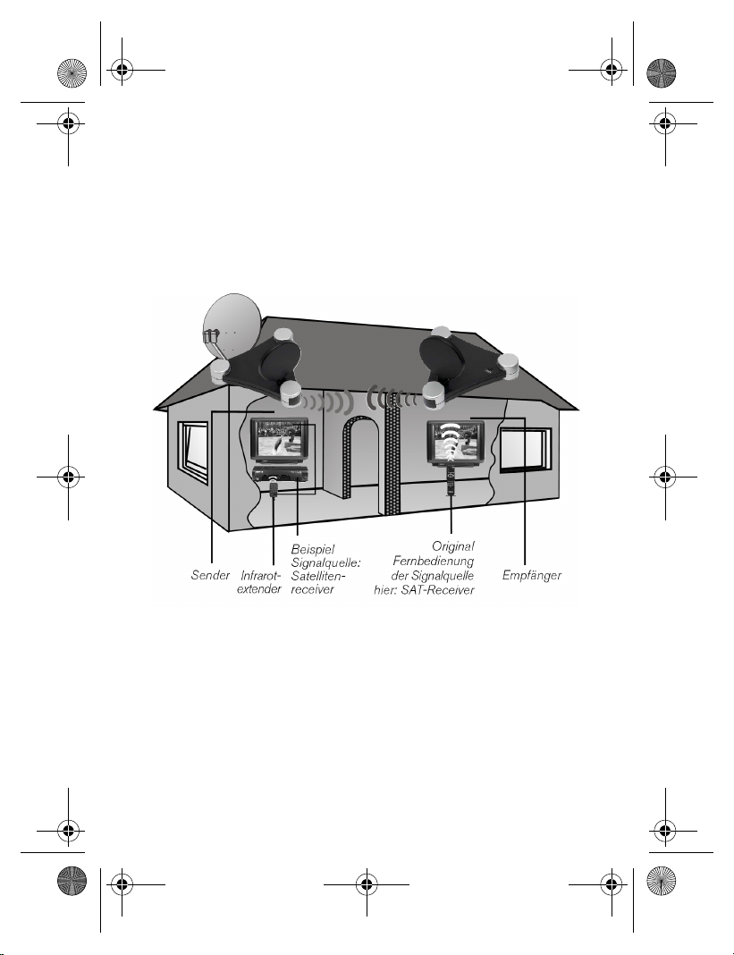
Mögliche Signalgeber und Empfänger
Eine typische Anwendung ist z. B., den Fernsehempfang eines Satelliten-Receivers als Quelle auf einen anderen Fernsehapparat im Haus weiterzuleiten. Andere Audio-/
Videoquellen können etwa ein DVD-Rekorder, ein Videorekorder, ein TV-Gerät, die „D-Box“ (Premiere) oder auch eine
PC-Karte sein. Das an den Empfänger angeschlossene Gerät kann z. B. ein Fernseher oder ein Verstärker sein.
6
Page 5

MD 81209 manual DE_GB_FR_IT_ES.book Seite 7 Montag, 27. Februar 2006 10:33 10
Funksender und -empfänger zuordnen
Der Sender des Funkübertragungssystems wird an die Audio-/Videoquelle, der Empfänger etwa an einen Fernseher
oder Videorecorder angeschlossen. Mithilfe der dreiadrigen
AV-Cinchkabel oder den SCART-Adaptern schließt man an
das System die drei Signalarten Video sowie Audio-rechts
und Audio-links an.
Die Audio-/Videoquelle fernbedienen
Sie können die Fernbedienung der Audio-/Videoquelle nutzen, um diese Geräte am Ort des Empfängers zu steuern. Die
Fernbedienungssignale (Infrarot) werden dabei in Funksignale gewandelt und übertragen. Der Sender wiederum wandelt
die Funksignale wieder in ein Infrarotsignale um. Die zwei Infrarotsender des Infrarotextenders geben diese Signale dann
zu den entsprechenden Geräten weiter.
Scart oder Cinch
Wenn die Audio-/Videoquelle einen SCART-Anschluss besitzt, nutzen Sie den SCART-Adapter für den Sender. Wenn
das an den Empfänger angeschlossene Gerät einen SCARTAnschluss besitzt, nutzen Sie den SCART-Adapter für den
Empfänger.
Besitzt das am Empfänger angeschlossene Gerät keinen
SCART-Anschluss, nutzen Sie eins der dreiadrigen Cinchkabel.
Wenn die Audio-/Videoquelle einen 3,5 mm Audioausgang
besitzt, nutzen Sie den mitgelieferten Audioadapter.
D
7
Page 6
MD 81209 manual DE_GB_FR_IT_ES.book Seite 8 Montag, 27. Februar 2006 10:33 10
Reichweiten
Audio- und Videosignale werden im 2,4 GHz-Bereich übertragen. Im freien Feld beträgt die Reichweite ca. 100 m, innerhalb von Gebäuden ca. 30 m. Je nach Umgebungsbedingung kann die Reichweite geringer ausfallen.
Anwendungsbeispiel
8
Page 7
MD 81209 manual DE_GB_FR_IT_ES.book Seite 9 Montag, 27. Februar 2006 10:33 10
LEGENDE
(Abbildungen auf der Ausklappseite)
Sender
1. Mini DIN Eingang 6. Eingang für Infrarotsender
„AV IN 1“ IR EXT.
2. Mini DIN Eingang 7. Audio-/Video-
„AV IN 2“ Sendeantenne
3. DC-Eingang 8. Betriebs-LED
12 V 200 mA
4. Mini DIN Ausgang 9. Schalter ON/OFF
AV OUT
5. Schalter Quelle 1/2 10. Kanalwahlschalter
(ca. 10 Sek. A/B/C/D
gedrückt halten)
Empfänger
1. Mini DIN Ausgang 5. Schalter Quelle 1/2
AV EXTEND (ca. 10 Sek.
gedrückt halten)
2. DC-Eingang 9 V 6. Schalter ON/OFF
400mA
3. Audio-/Video- 7. Kanalwahlschalter
Empfangsantenne A/B/C/D
4. Betriebs-LED/
Infrarotsender
D
9
Page 8
MD 81209 manual DE_GB_FR_IT_ES.book Seite 10 Montag, 27. Februar 2006 10:33 10
LIEFERUMFANG
Vergewissern Sie sich nach dem Auspacken, ob folgende
Teile mitgeliefert worden sind:
Sender:
• Sender
• Netzadapter für den Sender, 12 V 200 mA
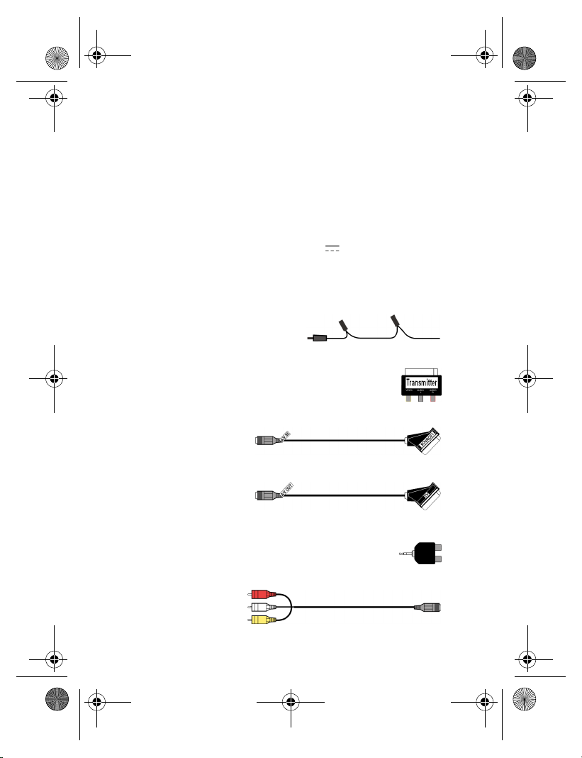
Zubehör:
• 1 Infrarotextender mit zwei externen IR-Sendern
• 1x SCART-Adapter für den Sender „Transmitter“
• 1x Mini DIN-SCART-Kabel für den A/V-Eingang
• 1x Mini DIN-SCART-Kabel für den A/V-Ausgang
• 1x Audioadapter 3,5 mm Klinkenstecker auf Cinchbuchse
• 1x Mini DIN-AV-Cinchkabel
10
Page 9
MD 81209 manual DE_GB_FR_IT_ES.book Seite 11 Montag, 27. Februar 2006 10:33 10
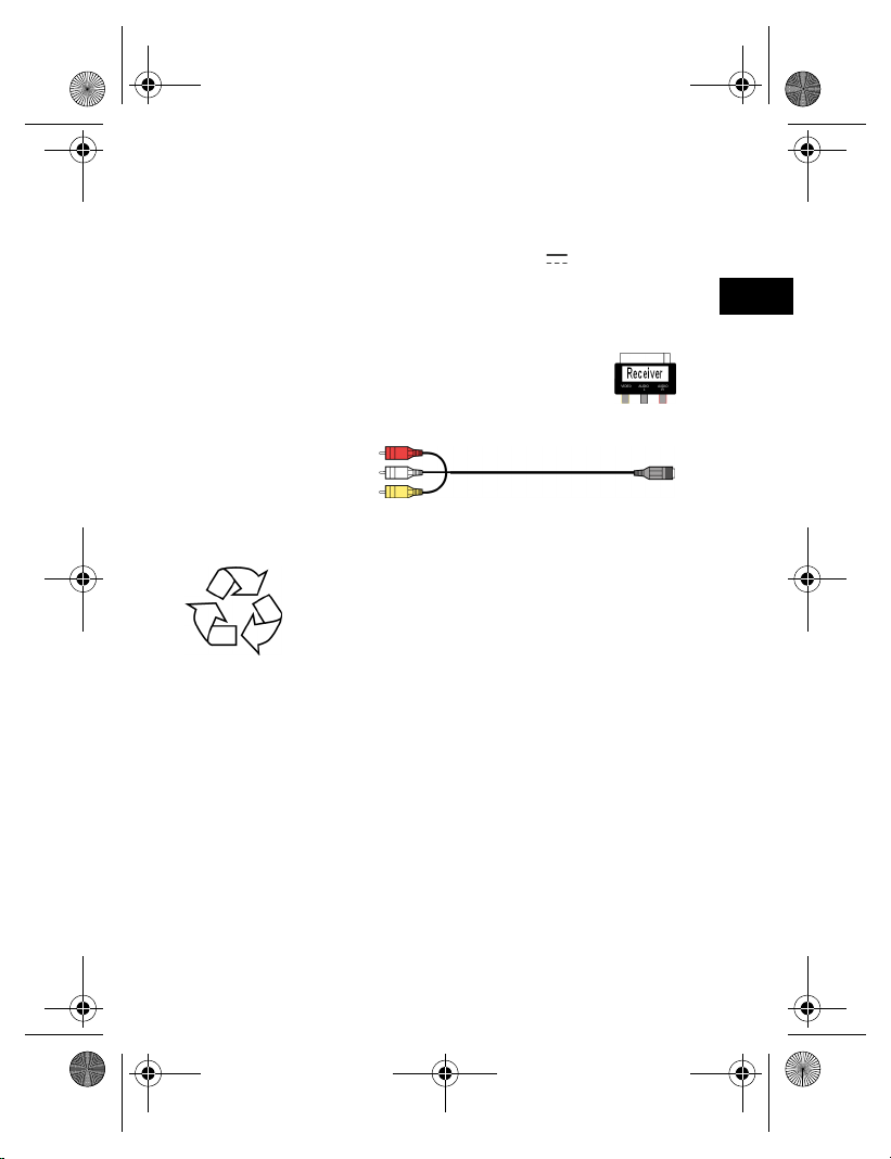
Empfänger:
• Empfänger
• 1x Netzadapter für den Empfänger, 9 V 400 mA
Zubehör:
1x SCART-Adapter für den Empfänger „Receiver“
1x Mini DIN-AV-Cinchkabel
Verpackung
Das Funkübertragungssystem befindet sich
zum Schutz vor Transportschäden in einer Verpackung. Verpackungen sind Rohstoffe, somit
wiederverwendungsfähig und können dem
Rohstoffkreislauf zugeführt werden.
D
11
Page 10

MD 81209 manual DE_GB_FR_IT_ES.book Seite 12 Montag, 27. Februar 2006 10:33 10
SENDER ANSCHLIESSEN
Der Sender wird mit einer Audio-/Videoquelle (Quelle 1) verbunden. Dies kann z. B. ein SAT-Empfänger, ein Videorekorder, ein DVD-Gerät, ein TV-Gerät oder auch eine Grafik-Karte
(siehe unten) sein.
Über SCART-Anschluss
Wenn die Audio-/Videoquelle einen SCART-Anschluss besitzt, verbinden Sie das mitgelieferte Mini DIN-SCART-Kabel
für den A/V-Eingang mit dem SCART-Ausgang dieses Geräts
und dem Mini DIN-Eingang (AV IN 1) am Sender.
Ohne SCART-Anschluss
Wenn die Audio-/Videoquelle keinen SCART-Anschluss besitzt, verbinden Sie das mitgelieferte Mini DIN-AV-Cinchkabel mit dem A/V-Cinch-Ausgang dieses Geräts und dem Mini
DIN-Eingang (AV IN 1) am Sender.
• Der gelbe Cinch-Stecker ist für einen Video-Anschluss, der
rote für Audio rechts, der weiße für Audio links.
• Um nur Tonsignale zu übertragen, verbinden Sie nur die
Audio-Stecker.
• Wenn Sie den Sender an eine 3,5 mm Audiobuchse einer
Audio-/Videoquelle anschließen möchten, verwenden Sie
den Audioadapter und verbinden diesen mit den AudioSteckern des Mini DIN-SCART-Cinchkabels.
• Verbinden Sie anschließend den Mini DIN-Stecker am anderen Ende des Mini DIN-AV-Cinchkabels mit der entsprechenden Buchse am Sender.
12
Page 11
MD 81209 manual DE_GB_FR_IT_ES.book Seite 13 Montag, 27. Februar 2006 10:33 10
• Um das Videosignal auch an ein Fernsehgerät weiterzuleiten, das dort platziert ist, wo der Sender aufgestellt wurde,
verbinden Sie das Mini DIN-SCART-Kabel für den A/V Ausgang (AV OUT) mit dem SCART-Eingang am Fernsehgerät.
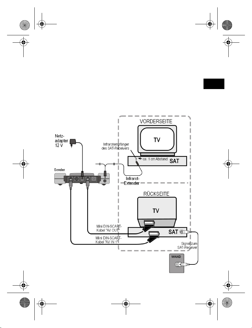
Beispielanordung Sender
Die folgende Skizze stellt eine Beispielanordnung mit einem
Satelliten-Receiver und einem TV-Gerät auf der Senderseite
dar:
D
13
Page 12
MD 81209 manual DE_GB_FR_IT_ES.book Seite 14 Montag, 27. Februar 2006 10:33 10
Infrarot Extender (für Fernbedienungen)
Um vom Ort des Empfängers aus die Audio-/Videoquelle
fernbedienen zu können, müssen Sie den Infrarot-Extender
anschließen.
• Verbinden Sie den Stecker des Infrarot-Extenders mit der
IR EXT Buchse am Sender (siehe Abbildung auf der vorherigen Seite).
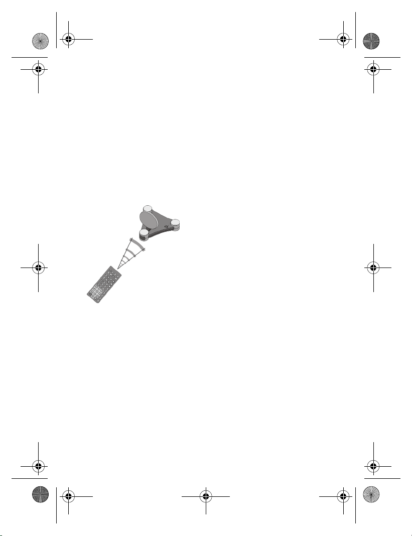
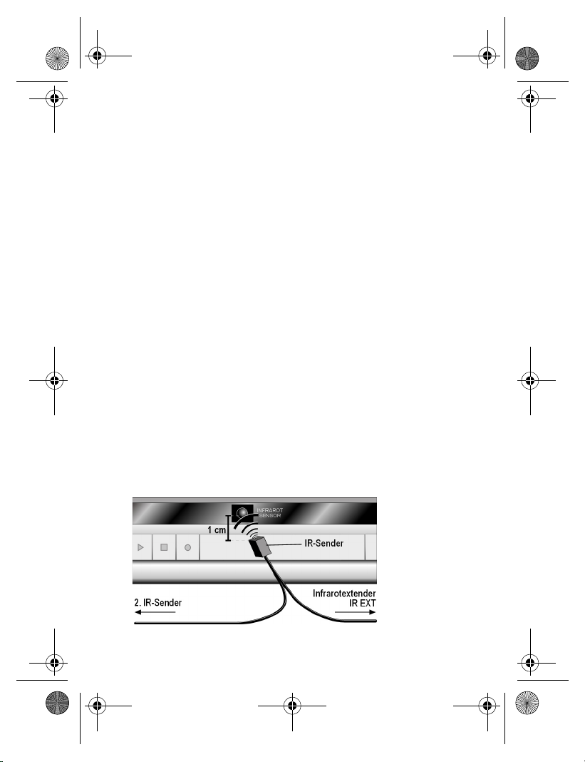
• Ziehen Sie das Papier von der Klebefläche eines der beiden
IR-Sender ab. Befestigen Sie den IR-Sender so an der Audio-/Video-Quelle, dass sie auf den Infrarotempfänger dieses Geräts gerichtet ist. Dabei muss die Oberseite der
Diode ca. 1 cm Abstand vom Infrarotempfänger haben
(siehe Abb. unten).
Mehrere Geräte nutzen
Da der Infrarot-Extender zwei IR-Sender hat, können Sie
mehrere Geräte gleichzeitig vom Ort des Empfängers aus
fernbedienen. So können Sie z. B. sowohl Videorekorder als
auch DVD-Player an einem anderen Ort nutzen.
• Befestigen Sie dazu jeweils einen IR-Sender wie oben beschrieben an jedem Gerät, das sie an einem anderen Ort
nutzen möchten.
14
Page 13

MD 81209 manual DE_GB_FR_IT_ES.book Seite 15 Montag, 27. Februar 2006 10:33 10
Mehrere Geräte anschließen
Sie können auch ein zweites Gerät an den Sender anschließen, die Signale dieses Geräts an den Empfänger weiterleiten und von dort aus dieses Gerät mit der Fernbedienung
steuern.
• Wenn Sie das Gerät an den AV IN 1 Eingang des Senders
angeschlossen haben, ist das Gerät als Quelle 1 definiert,
beim Anschluss an den AV IN 2 Eingang des Senders als
Quelle 2.
• Über den Schalter SOURCE 1/2 am Sender können Sie nun
einstellen, welches Signal an den am AV OUT Ausgang angeschlossenen Fernseher weitergegeben wird.
D
15
Page 14
MD 81209 manual DE_GB_FR_IT_ES.book Seite 16 Montag, 27. Februar 2006 10:33 10
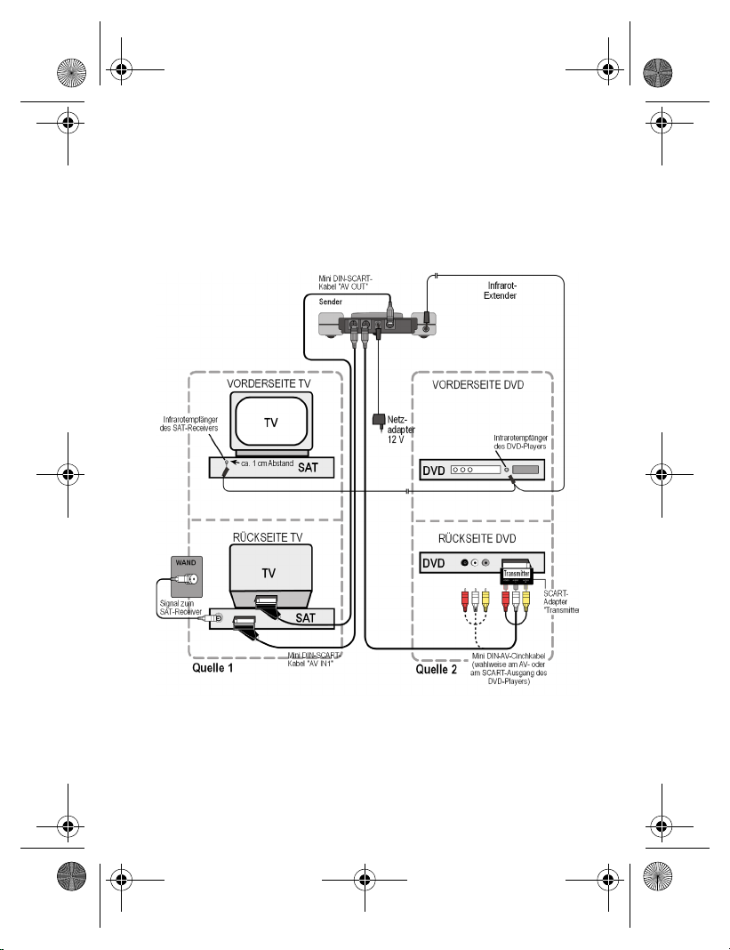
Beispielanordung Sender mit zwei Geräten
Die folgende Skizze stellt eine Beispielanordnung mit einem
Satelliten-Receiver, einem TV-Gerät und einem DVD-Player
auf der Senderseite dar:
16
Page 15

MD 81209 manual DE_GB_FR_IT_ES.book Seite 17 Montag, 27. Februar 2006 10:33 10
Netzadapter anschliessen
• Schließen Sie den Netzadapter für den Sender an die 12 VAnschlussbuchse (DC 12 V) des Senders an.
• Nehmen Sie die Schutzkappe ab und stecken Sie den
Netzadapter in die Steckdose (230 V ~ 50 Hz).
• Stellen Sie den ON/OFF-Schalter auf die Position ON. Die
rote Betriebs LED leuchtet.
• Klappen Sie die Sendeantenne auf und richten Sie sie in
Richtung Empfänger aus.
Kanal wählen
• Wählen Sie mit dem Kanalwahlschalter an der Unterseite
des Geräts einen Kanal (A/B/C/D) aus, auf dem gesendet
werden soll.
Aufstellen
• Stellen Sie den Sender auf eine feste Oberfläche.
• Richten Sie die Sendeantenne mit der flachen Seite in Richtung des Empfängers aus.
D
17
Page 16

MD 81209 manual DE_GB_FR_IT_ES.book Seite 18 Montag, 27. Februar 2006 10:33 10
SENDER AN EINEN COMPUTER
ANSCHLIESSEN
Sie können den Sender auch an einen Computer anschließen, um die Computerausgabe z. B. auf ein Fernsehgerät zu
übertragen.
Die Übertragung der Computerausgabe auf ein Fernsehgerät
ist meistens nicht sinnvoll, wenn eine Computeranwendung
darauf ablaufen soll. Die Bildausgabe des TV-Geräts reicht in
der Regel nicht aus, um das höher aufgelöste Computerbild
anzuzeigen.
Werden allerdings Videos oder Präsentationen wiedergegeben, ist die Ausgabe über einen Fernseher durchaus empfehlenswert.
Folgende Voraussetzungen müssen gewährleistet sein:
• Ihr Computer hat einen Videoausgang, der die Bildausgabe
auf ein TV-Gerät unterstützt.
• Das Betriebssystem und der Treiber Ihrer Grafikkarte unterstützen den Videoausgang.
Vorgehensweise
Abhängig von der Grafikkarte und dem Betriebssystem wird
die Ausgabe über den Videoausgang unterschiedlich aktiviert. Da es eine Vielzahl von Kombinationen gibt, können wir
hier nur eine allgemeine Anleitung geben. Lesen Sie bitte in
der Bedienungsanleitung Ihres Computers bzw. der Grafikkarte nach, wie das Bild auf den Videoausgang umgeleitet
wird.
Das nachfolgende Beispiel setzt einen PC mit dem Betriebssystem Windows® ab der Version 98 voraus.
18
Page 17
MD 81209 manual DE_GB_FR_IT_ES.book Seite 19 Montag, 27. Februar 2006 10:33 10
• Beenden Sie alle Programme und schalten Sie den Computer aus.
• Nehmen Sie die Bedienungsanleitung Ihres PCs zur Hand
und folgen Sie den Anweisungen zur Nutzung des Videoausgangs.
• Schließen Sie den gelben Stecker des AV-Cinchkabels an
den Videoausgang der Grafikkarte an. Sollte Ihre Grafikkarte nicht über einen Cinch-Ausgang verfügen, benutzen Sie
einen entsprechenden Adapter (Sonderzubehör).
• Stecken Sie nun den roten und den weißen Stecker des
Mini DIN-AV-Cinchkabels in den passenden Audioausgang
Ihres PCs. Meist verfügen PCs über 3,5-mm-Klinkenbuchsen, so dass Sie hier den mitgelieferten Adapter verwenden
können.
• Nun schließen Sie den Mini DIN-Stecker des Kabels an den
Eingang AV IN 1 der Sendestation an.
• Schalten Sie nun die Sende- und die Empfangsstation sowie Ihr TV-Gerät ein und wählen den passenden Videokanal an Ihrem TV-Gerät.
• Starten Sie den PC und warten Sie, bis das Betriebssystem
vollständig geladen ist.
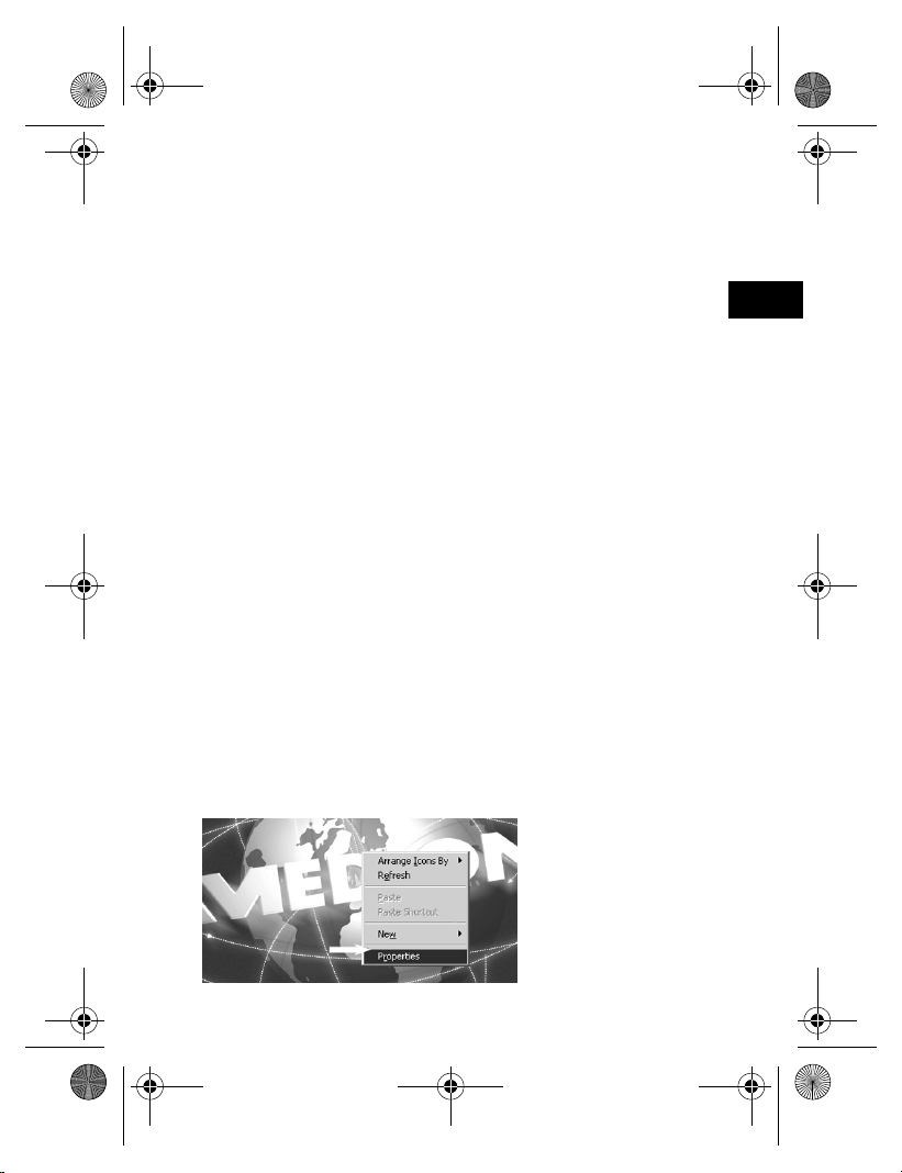
• Klicken Sie nun mit der rechten Maustaste einmal auf den
Desktop (Arbeitsfläche) und wählen Sie „Eigenschaften“,
um die „Eigenschaften für Anzeige“ anzuzeigen:
D
19
Page 18
MD 81209 manual DE_GB_FR_IT_ES.book Seite 20 Montag, 27. Februar 2006 10:33 10
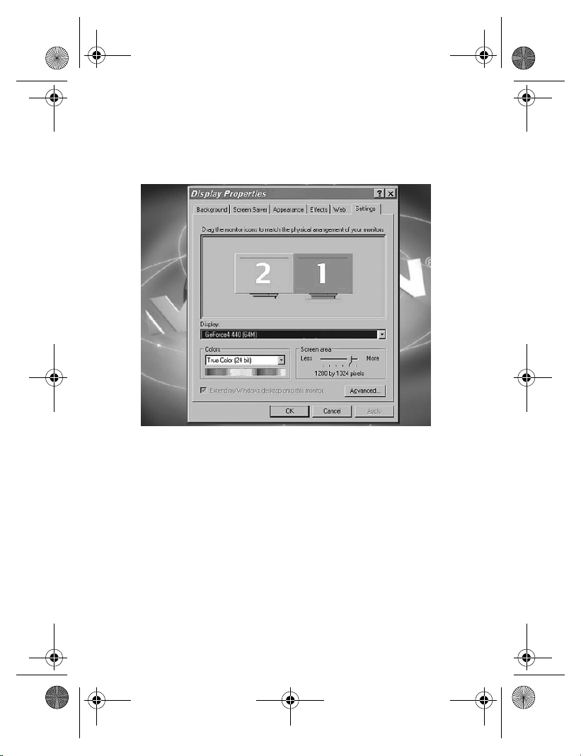
• Klicken Sie nun auf „Einstellungen“, um die Ausgabe Ihres
PCs entsprechend zu konfigurieren. Es gibt hier enorme
Abweichungen zwischen den unterschiedlichen Grafikkarten.
Lesen Sie daher in der entsprechenden Bedienungsanleitung
nach, wie Sie nun weiter vorgehen müssen. Meist kann auch
die Online-Hilfe mit der Taste F1 aufgerufen werden, um detaillierte Informationen zu erhalten.
Wenn Sie die Einstellungen korrekt vorgenommen haben,
wird das Bild des PCs nun auf dem TV-Gerät wiedergegeben.
20
Page 19
MD 81209 manual DE_GB_FR_IT_ES.book Seite 21 Montag, 27. Februar 2006 10:33 10
Warenzeichen
MS-DOS® und Windows® sind eingetragene Warenzeichen
der Fa. Microsoft®.
Pentium® ist ein eingetragenes Warenzeichen der Firma Intel®.
Haftpflichtbeschränkung für Datenverlust/Folgeschäden
Datensicherung:
Bei jeder Veränderung des PC-Systems sollten Sie eine Da-
tensicherung auf externen Medien (z. B. CD-R) durchführen,
um Datenverlust zu vermeiden. Für verloren gegangene Daten haftet die MEDION AG nicht.
Funktionalität:
Aufgrund der enormen Unterschiede bei Betriebssystemen
und Grafikkarten können wir die in diesem Kapitel ("Sender an
einen Computer anschließen") beschriebene Funktionalität
nicht pauschal garantieren. Bitte informieren Sie sich bei einem zuständigen Fachhändler/Fachmann.
Folgeschäden:
Bitte beachten Sie beim Anschluss des Funkübertragungssy-
stems unbedingt die Gebrauchsanweisungen Ihres Computers, der verwendeten Software und der Zusatzkomponenten.
Wir haften nicht für Schäden oder Datenverluste, die durch
Fehlanwendung oder nicht bestimmungsgemäßen Gebrauch
entstanden sind.
D
21
Page 20

MD 81209 manual DE_GB_FR_IT_ES.book Seite 22 Montag, 27. Februar 2006 10:33 10
EMPFÄNGER ANSCHLIESSEN
Es gibt mehrere Möglichkeiten, Audio-/Video-Signale des
Senders auf einem anderen Gerät zu empfangen.
Anschluss über ein DIN-AV-Cinchkabel
• Verbinden Sie das Mini DIN-AV-Cinchkabel mit dem Ausgang AV EXTEND des Empfängers und den entsprechenden Buchsen am empfangenden Gerät (z. B. dem
Fernseher).
Anschluss über SCART-Adapter
• Verbinden Sie das Mini DIN-AV-Cinchkabel mit dem Ausgang AV EXTEND des Empfängers und dem SCART-Adapter für den Empfänger.
• Stecken Sie den SCART-Adapter mit dem Aufdruck „Receiver“ in den SCART-Eingang des empfangenden Geräts
(z. B. den Fernseher).
22
Page 21
MD 81209 manual DE_GB_FR_IT_ES.book Seite 23 Montag, 27. Februar 2006 10:33 10
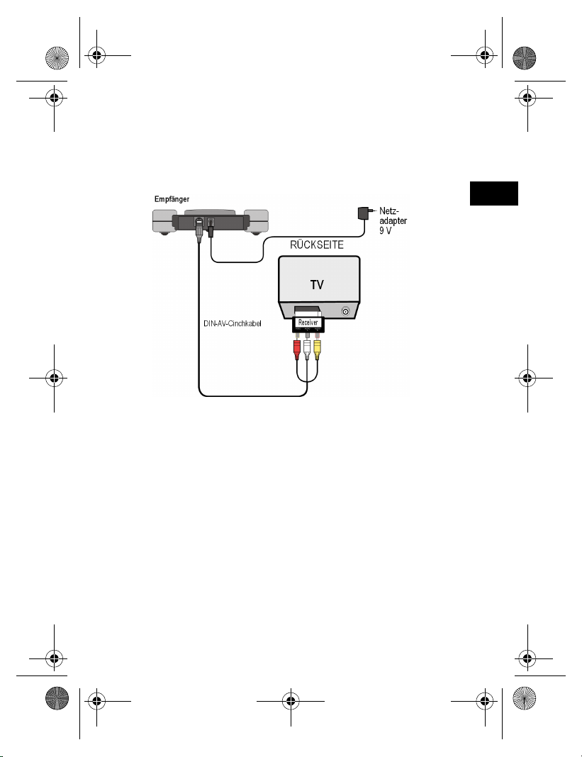
Beispielanordung Empfänger
Die folgende Skizze stellt eine Beispielanordung des Empfängers und eines Fernsehgeräts wahlweise mit dem MiniDIN-AV-Cinchkabel oder einem SCART-Adapter dar.
Gerät zwischenschalten
Statt den Empfänger direkt mit einem Fernseher zu verbinden, können Sie auch ein anderes Audio-/Videogerät zwischenschalten. Dies könnte z. B. ein Videorekorder sein, den
Sie dann auf die beschriebenen Arten mit dem Empfänger
verbinden können.
D
Netzadapter anschliessen
• Schließen Sie den Netzadapter für den Empfänger an die 9Volt-Anschlussbuchse des Empfängers an.
• Stecken Sie den Netzadapter in eine gut erreichbare Steckdose (230 V ~ 50 Hz).
23
Page 22

MD 81209 manual DE_GB_FR_IT_ES.book Seite 24 Montag, 27. Februar 2006 10:33 10
• Schalten Sie das empfangende Gerät (z. B. den Fernseher)
ein und stellen Sie den ON/OFF-Schalter des Empfängers
auf ON. Die rote Betriebs-LED leuchtet.
Kanal wählen
Achten Sie darauf, dass der Empfänger auf den gleichen Kanal (A/B/C/D) eingestellt ist, wie der Sender.
Quelle wählen
Falls Sie zwei Geräte an den Sender angeschlossen haben
sollten, können Sie nun mit dem Schalter Schalter SOURCE
1/2 zwischen dem Empfang des ersten (Quelle 1) und des
zweiten Geräts (Quelle 2) umschalten.
• Halten Sie hierzu die Taste SOURCE 1/2 an der Rückseite
des Empfängers für etwa 10 Sekunden lang gedrückt, bis
das Gerät umschaltet.
• Sie können auch eine beliebige Taste auf der Fernbedienung eines an den Sender angeschlossenen Geräts für
etwa 10 Sekunden gedrückt halten, bis das Gerät umschaltet.
Aufstellen
• Stellen Sie den Empfänger auf eine feste Oberfläche.
• Stellen Sie den Empfänger so auf, dass die Front mit der
LED-Betriebsanzeige in Ihre Richtung weist.
• Wenn Sie die Fernbedienung der Audio-/Video-Quelle benutzen, halten Sie sie in Richtung Empfänger.
• Klappen Sie die Empfangsantenne auf und richten Sie sie
in Richtung Sender aus, bis Sie ein optimales Bild haben.
24
Page 23

MD 81209 manual DE_GB_FR_IT_ES.book Seite 25 Montag, 27. Februar 2006 10:33 10
KANALEINSTELLUNG
Ihr Funkübertragungssystem ist mit vier Kanälen ausgestattet, d. h. es kann auf vier verschiedenen Frequenzen senden.
Der Kanalschalter finden Sie bei beiden Geräten auf der Unterseite.
• Stellen Sie Sender und Empfänger auf denselben Kanal ein.
• Probieren Sie aus, welcher der Kanäle A, B, C oder D den
besten Empfang liefert.
• Sie können die vier Kanäle auch dazu nutzen, bis zu vier
Funkübertragungssysteme einzusetzen.
D
25
Page 24
MD 81209 manual DE_GB_FR_IT_ES.book Seite 26 Montag, 27. Februar 2006 10:33 10
REINIGUNG/ENTSORGUNG
Reinigung
• Verwenden Sie zum Reinigen ein trockenes, weiches Tuch.
• Verwenden Sie keine Reinigungslösungen, die die Oberfläche der Geräte angreifen können. Sprühen Sie den Reiniger niemals direkt auf die Geräte.
Entsorgung
Werfen Sie das Funkübertragungssystem am Ende
seiner Lebenszeit keinesfalls in den normalen
Hausmüll. Erkundigen Sie sich in Ihrer Stadt- oder
Gemeinde-verwaltung nach Möglichkeiten einer
umwelt- und sachgerechten Entsorgung.
26
Page 25

MD 81209 manual DE_GB_FR_IT_ES.book Seite 27 Montag, 27. Februar 2006 10:33 10
WENN STÖRUNGEN AUFTRETEN
Falls Störungen auftreten sollten , prüfen Sie bitte zunächst,
ob die Anlage richtig eingerichtet ist. Folgende Übersicht
kann Ihnen dabei helfen:
Keine Audio/Video Übertragung
• Sind die Netzadapter eingesteckt?
• Sind Sender und Empfänger eingeschaltet?
• Sind die Kanäle für Sender und Empfänger gleich eingestellt?
• Ist die Übertragungsquelle eingeschaltet?
• Mauern und Decken verringern die Reichweite.
• Überprüfen Sie die Verbindungen an den angeschlossenen
Geräten.
Schlechte Empfangsqualität
• Richten Sie die Antennen von Sender und Empfänger noch
einmal aufeinander aus.
• Verändern Sie die Position des Senders und Empfängers
ein wenig.
• Es kann durch verschiedene Einflüsse wie Wellen anderer
Radiogeräte zu Beeinträchtigungen kommen.
• Wählen Sie einen anderen Kanal.
Fernbedienung reagiert nicht
• Halten Sie die Fernbedienung direkt in Richtung Empfänger.
• Die Dioden des Infrarotsenders müssen ca. 1 cm Abstand
von dem Infrarotempfänger der Audio-/Video-Quelle haben.
• Haben Sie die IR-Dioden richtig ausgerichtet?
D
27
Page 26
MD 81209 manual DE_GB_FR_IT_ES.book Seite 28 Montag, 27. Februar 2006 10:33 10
TECHNISCHE DATEN
Sender:
Netzadapter
Eingang: 230 V ~ 50 Hz
Ausgang: 12 V 200 mA
4 Kanäle
Frequenzbereich: 2,4000 - 2,4835 GHz
Anschlüsse: 1 Mini-DIN-Ausgang
2 Mini-DIN-Eingänge
Rückkanal für
Fernbedienungssignal: 433 MHz
Empfänger:
Netzadapter
Eingang: 230 V ~ 50 Hz
Ausgang: 9V 400mA
4 Kanäle
Frequenzbereich: 2,4000 - 2,4835 GHz
Anschlüsse: 1 Mini-DIN-Ausgang
Die Netzadapter sind GS-geprüft.
Technische Änderungen vorbehalten!
28
Page 27
MD 81209 manual DE_GB_FR_IT_ES.book Seite 29 Montag, 27. Februar 2006 10:33 10
KONFORMITÄTSINFORMATION
Hiermit erklärt Medion AG, dass sich das Gerät MD 81209 in
Übereinstimmung mit den grundlegenden Anforderungen
und den anderen relevanten Vorschriften der Richtlinie 1999/
5/CE befindet.
Auf Wunsch erhalten Sie weitere Informationen zur Konformitätserklärung von unserem Service-Center.
Geprüft für den Betrieb in allen EU-Ländern.
D
29
Page 28

MD 81209 manual DE_GB_FR_IT_ES.book Seite 30 Montag, 27. Februar 2006 10:33 10
30
Page 29
MD 81209 manual DE_GB_FR_IT_ES.book Seite 3 Montag, 27. Februar 2006 10:33 10
CONTENTS
Safety instructions . . . . . . . . . . . . . . . . . . 4
About this appliance . . . . . . . . . . . . . . . . . .6
Key . . . . . . . . . . . . . . . . . . . . . . . . . . . . . . .9
Contents of package. . . . . . . . . . . . . . . . .10
Connecting the transmitter . . . . . . . . . . .12
Via SCART connection . . . . . . . . . . . . . . . . . . . . . . . . . . . .12
No SCART connection . . . . . . . . . . . . . . . . . . . . . . . . . . . . 12
Infrared extender (for remote control) . . . . . . . . . . . . . . . 14
Connecting the mains adapter . . . . . . . . . . . . . . . . . . . . . 17
Selecting a channel . . . . . . . . . . . . . . . . . . . . . . . . . . . . . . 17
Setting up . . . . . . . . . . . . . . . . . . . . . . . . . . . . . . . . . . . . . . 17
Connecting the transmitter
to a computer . . . . . . . . . . . . . . . . . . . . . .18
Connecting the receiver . . . . . . . . . . . . . .22
Connecting via a DIN AV cinch cable . . . . . . . . . . . . . . . . 22
Connecting via the SCART adapter . . . . . . . . . . . . . . . . . 22
Interposing a device . . . . . . . . . . . . . . . . . . . . . . . . . . . . . 23
Connecting the mains adapter . . . . . . . . . . . . . . . . . . . . . 23
Selecting a channel . . . . . . . . . . . . . . . . . . . . . . . . . . . . . . 24
Selecting the source . . . . . . . . . . . . . . . . . . . . . . . . . . . . . 24
Setting up . . . . . . . . . . . . . . . . . . . . . . . . . . . . . . . . . . . . . . 24
Setting channels . . . . . . . . . . . . . . . . . . .25
Cleaning/disposal. . . . . . . . . . . . . . . . . . .26
Troubleshooting . . . . . . . . . . . . . . . . . . . 27
Technical data . . . . . . . . . . . . . . . . . . . . 28
Ration of conformity . . . . . . . . . . . . . . . .29
GB
3
Page 30
MD 81209 manual DE_GB_FR_IT_ES.book Seite 4 Montag, 27. Februar 2006 10:33 10
SAFETY INSTRUCTIONS
Please read these instructions carefully
before using the system and note the
warnings in the operating instructions. Always
keep the operating instructions close to
hand.
If you sell the appliance or give it away, please ensure that
you also pass on these instructions.
Environmental requirements
• Protect the device from moisture and heat.
• Avoid placing the devices in poorly ventilated areas (such
as between shelves or where curtains or furniture can
block the vents).
• Do not allow foreign bodies or liquids to get into the
device. Do not expose the devices to water.
• Naked flames such as lit candles must not be placed on
the devices.
• The rubber feet on the devices may leave marks on
furniture surfaces. Place the devices on a suitable
underlay if necessary.
Power connection
Never allow children to use electrical appliances
unattended.
• Connect the mains adapters to easily
accessible 230V ~ 50Hz power sockets only.
4
Page 31

MD 81209 manual DE_GB_FR_IT_ES.book Seite 5 Montag, 27. Februar 2006 10:33 10
• Use only the mains adapters supplied.
• Never try to connect the mains adapters to other
connectors as this may damage the devices.
• If a mains adapter is damaged, it should not be used.
Replace it with the same type of mains adapter.
Fau lts
• Remove the mains adapter(s) from the power socket
immediately if the mains adapter, the connection cable or
the devices are damaged.
• Never try to open and/or repair the devices yourself.
• Contact our service centre or qualified personnel.
Health Issues
• The low transmitting power of the devices eliminates any
danger to health according to the current state of
research and technology.
GB
5
Page 32

MD 81209 manual DE_GB_FR_IT_ES.book Seite 6 Montag, 27. Februar 2006 10:33 10
ABOUT THIS APPLIANCE
Your radio transmission system transmits signals wirelessly
from an audio/video source to another audio/video device.
Typically, the radio signals are sent from a source with an
aerial (e.g. a SAT receiver) to another device without an
aerial (e.g. a different TV in the building) so that the first
device's aerial can be used for the second device.
You can use the source remote
control to control this device via
the receiver. Your system will work
over distances of up to 100m
outdoors and 30m indoors.
It is also possible to connect the
radio transmission system to a PC,
for instance to transmit digital
presentations onto a TV.
Possible signal transmitters and receivers
Typically, the system may be used to transfer the television
reception from a satellite receiver, as the source, to another
television in your house. Other audio/video sources can be
a DVD recorder, a video recorder or a television, the "D
Box" (Premiere) or even a PC card. The device connected to
the receiver may be, for example, a television or an
amplifier.
6
Page 33

MD 81209 manual DE_GB_FR_IT_ES.book Seite 7 Montag, 27. Februar 2006 10:33 10
Assigning the radio transmitter and receiver
The transmitter in the radio transmission system is
connected to the audio/video source and the receiver is
connected to a television or video recorder. The threecore
AV cinch cable or the SCART adapter is used to connect the
three types of signal – video, audio right and audio left – to
the system.
Controlling the audio/video source remotely
You can use the audio/video source remote control to
control these devices from the point where the receiver is
located. The (infrared) remote control signals are converted
and transmitted as radio signals. The transmitter converts
the radio signals back into an infrared signal. The two
infrared transmitters in the infrared extender then send
these signals on to the relevant devices.
Scart or Cinch
If the audio/video source has a SCART connection, use the
SCART adapter for the transmitter. If the device connected
to the receiver has a SCART connection use the SCART
adapter for the receiver.
If the device connected to the receiver does not have a
SCART connection use one of the threecore cinch cables.
If the audio/video source has a 3.5mm audio output use the
audio adapter supplied.
GB
7
Page 34

MD 81209 manual DE_GB_FR_IT_ES.book Seite 8 Montag, 27. Februar 2006 10:33 10
Range
Audio and video signals are transmitted in the 2.4GHz
range. The range is approx. 100m in the open air and
approx. 30m inside. The range may be less depending on
environmental conditions.
Example use
8
Page 35

MD 81209 manual DE_GB_FR_IT_ES.book Seite 9 Montag, 27. Februar 2006 10:33 10
KEY
(Diagrams on foldout page)
Transmitter
1. Mini DIN input 6. Input for infrared
"AV IN 1" transmitter IR EXT.
2. Mini DIN input 7. Audio/video
"AV IN 2" transmitter aerial
3. DC input 8. Operating LED
12V 200mA
4. Mini DIN output 9. ON/OFF switch
AV OUT
5. Switch source 1/2 10.Channel switch
(hold down for A/B/C/D
approx. 10 secs.)
Receiver
1. Mini DIN output 5. Switch source 1/2
AV EXTEND (hold down for
approx. 10 secs.)
2. DC input 9V 6. ON/OFF switch
400mA
3. Audio / video 7. Channel switch
Receiver aerial A/B/C/D
4. Operating LED/
infrared transmitter
GB
9
Page 36

MD 81209 manual DE_GB_FR_IT_ES.book Seite 10 Montag, 27. Februar 2006 10:33 10
CONTENTS OF PACKAGE
When you have unpacked everything, check that the parts
below have been included:
Transmitter:
• Transmitter
• Mains adapter for the transmitter, 12V 200mA
Accessories:
• 1 infrared extender with two external IR transmitters
• 1x SCART adapter for the "Transmitter"
• 1x Mini DIN SCART cable for the A/V input
• 1x Mini DIN SCART cable for the A/V output
• 1x audio adapter 3.5mm stereo jack to cinch socket
• 1x Mini DIN AV cinch cable
10
Page 37

MD 81209 manual DE_GB_FR_IT_ES.book Seite 11 Montag, 27. Februar 2006 10:33 10
Receiver:
• Receiver
• 1x mains adapter for the receiver, 9V 400mA
Accessories:
1x SCART adapter for the "Receiver"
1x Mini DIN AV cinch cable
Packaging
The radio transmission system is packaged to
protect it against transportation damage.
Packaging is raw material and can be reused
or added to the recycling system.
GB
11
Page 38

MD 81209 manual DE_GB_FR_IT_ES.book Seite 12 Montag, 27. Februar 2006 10:33 10
CONNECTING THE TRANSMITTER
The transmitter is connected to an audio/video source
(Source 1). This can be a SAT receiver, a video recorder, a
DVD player, a television or even a graphics card (see
below).
Via SCART connection
If the audio / video source has a SCART connection,
connect the Mini DIN SCART cable for the A/V input
(supplied) to this device's SCART output, and the Mini DIN
input (AV IN 1) to the transmitter.
No SCART connection
If the audio/video source has no SCART connection,
connect the Mini DIN AV cinch cable (supplied) to this
device's A/V cinch output, and the Mini DIN input (AV IN 1)
to the transmitter.
• The yellow cinch plug is for a video connection, the red
one is for audio right, and the white one is for audio left.
• If you want to transmit sound signals only, connect the
audio plugs only.
• If you want to connect the transmitter to a 3.5mm audio
jack on an audio/video source, use the audio adapter and
connect it to the audio plugs on the Mini DIN SCART cinch
cable.
• Then connect the Mini DIN plug on the other end of the
Mini DIN AV cinch cable to the appropriate socket on the
transmitter.
12
Page 39

MD 81209 manual DE_GB_FR_IT_ES.book Seite 13 Montag, 27. Februar 2006 10:33 10
• To send the video signal on to a TV set positioned where
the transmitter has been set up, connect the Mini DIN
SCART cable for the A/V output (AV OUT) to the SCART
input on the TV.
Example of transmitter setup
The following diagram shows a typical arrangement with a
satellite receiver and a TV on the transmitter side:
GB
13
Page 40

MD 81209 manual DE_GB_FR_IT_ES.book Seite 14 Montag, 27. Februar 2006 10:33 10
Infrared extender (for remote control)
You have to connect the infrared extender if you want to be
able to use the remote control from where the receiver is
positioned.
• Connect the plug on the infrared extender to the IREXT
socket on the transmitter (see diagram on previous page).
• Remove the paper backing from the sticky surface of one
of the two IR transmitters and stick the IR transmitter onto
the audio/video source so that it is aligned with the
infrared receiver on this device. The top of the diode
should be approx. 1 cm away from the infrared receiver
(see diagram below).
Using more than one device
As the infrared extender has two IR transmitters, you can
simultaneously operate more than one device remotely
from the receiver. For example, you can use the video
recorder as well as the DVD player in another room.
• Attach an IR transmitter as described above to each
device that you want to use in another location.
Connecting more than one device
You can also connect a second device to the transmitter that
14
Page 41

MD 81209 manual DE_GB_FR_IT_ES.book Seite 15 Montag, 27. Februar 2006 10:33 10
can send signals from this device to the receiver and control
this device remotely from there.
• If you have connected the device to the transmitter's AV IN
1 input, the device is defined as Source 1, whereas it will
be Source 2 if connected to the transmitter's AV IN 2 input.
• You can now use the SOURCE 1/2 switch on the
transmitter to choose which signal is transmitted to the TV
connected to the AV OUT output.
GB
15
Page 42

MD 81209 manual DE_GB_FR_IT_ES.book Seite 16 Montag, 27. Februar 2006 10:33 10
Example of transmitter setup with two devices
The following diagram shows a typical arrangement with a
satellite receiver, a TV and a DVD player on the transmitter
side:
16
Page 43

MD 81209 manual DE_GB_FR_IT_ES.book Seite 17 Montag, 27. Februar 2006 10:33 10
Connecting the mains adapter
• Connect the mains adapter for the transmitter to the 12V
socket (DC 12V) on the transmitter.
• Remove the protective cover and insert the mains adapter
into the socket (230V ~ 50Hz).
• Set the ON/OFF switch to the ON position. The red
operating LED will light up.
• Open up the transmitter aerial and align it with the
receiver.
Selecting a channel
• Use the channel switch at the bottom of the device to
select a channel (A/B/C/D) to which the signal is to be
sent.
Setting up
• Place the transmitter on a sturdy surface.
• Align the flat side of the transmitter aerial with the receiver.
GB
17
Page 44

MD 81209 manual DE_GB_FR_IT_ES.book Seite 18 Montag, 27. Februar 2006 10:33 10
CONNECTING THE TRANSMITTER TO A
COMPUTER
You can also connect the transmitter to a computer in order
to transmit computer output to a television, for example.
It does not usually make sense to transmit computer output
to a TV for running computer applications, since the TV’s
screen display is not usually good enough to display the
higher resolution computer image.
If you want to show videos or presentations, however,
displaying them via the TV is highly recommended.
The following requirements have to be fulfilled:
• Your computer has a video output that provides video
images suitable for a TV.
• The operating system and the drivers for your graphics
card support video output.
How to proceed
Output via video output is activated differently depending on
your operating system and graphics card. As there are
numerous combinations of these, we can only provide
general instructions here. Please check the operating
instructions for your computer or graphics card to see how
you can divert the image to video output.
The following example requires a PC running the Windows®
98 operating system or above.
18
Page 45

MD 81209 manual DE_GB_FR_IT_ES.book Seite 19 Montag, 27. Februar 2006 10:33 10
• Close all programs and switch off your computer.
• Refer to the operating instructions for your PC and follow
the instructions for using video output.
• Connect the yellow plug on the AV cinch cable to the
graphics card’s video output. If your graphics card does
not have a cinch output, use a suitable adapter (optional
accessory).
• Connect the red and white plugs on the Mini DIN AV cinch
cable to the appropriate audio output on your PC. PCs
usually have 3.5mm stereo jacks, so you can use the
adapter supplied.
• Connect the cable's Mini DIN plug to the transmitter's AV
IN 1 input.
• Now switch on the transmitting station, the receiving
station and your TV, and choose the appropriate video
channel on your TV.
• Start your PC and wait until the operating system has fully
loaded.
• Rightclick once on the Desktop and choose "Properties"
to show the "Display Properties":
GB
• Now click on "Settings" to configure your PC’s output.
19
Page 46

MD 81209 manual DE_GB_FR_IT_ES.book Seite 20 Montag, 27. Februar 2006 10:33 10
Various graphics cards can differ enormously here.
You should therefore check the relevant operating
instructions to see how you should proceed. You can usually
use the F1 key to call up online help, which provides you with
detailed information.
If all the settings are correct, the image from the PC will now
be displayed on the TV.
20
Page 47

MD 81209 manual DE_GB_FR_IT_ES.book Seite 21 Montag, 27. Februar 2006 10:33 10
Trademarks
MS DOS® and Windows® are registered trademarks of
Microsoft®.
Pentium® is a registered trademark of Intel®.
Limitation of liability for loss of data/consequential losses
Backup:
To avoid loss of data you should back up all data to external
media (such as CDR) each time you change your PC
system. MEDION AG accepts no liability for loss of data.
Functionality:
The enormous differences between operating systems and
graphics cards mean that we cannot guarantee the
functionality described in this section ("Connecting the
transmitter to a computer"). Please contact a specialist
supplier or expert.
Consequential losses:
When you connect the radio transmission system to your
computer, you must take note of the operating instructions
for your computer, the software used and additional
components.
We are not liable for damages or loss of data that were
caused by incorrect or improper use.
GB
21
Page 48

MD 81209 manual DE_GB_FR_IT_ES.book Seite 22 Montag, 27. Februar 2006 10:33 10
CONNECTING THE RECEIVER
There are several ways to receive the transmitter’s audio/
video signals on a different device.
Connecting via a DIN AV cinch cable
• Connect the Mini DIN AV cinch cable to the receiver's AV
EXTEND output and the corresponding sockets on the
receiving device (e.g. the TV).
Connecting via the SCART adapter
• Connect the Mini DIN AV cinch cable to the receiver's AV
EXTEND output and the SCART adapter for the receiver.
• Plug the SCART adapter labelled "Receiver" into the
SCART input on the receiving device (e.g. the TV).
22
Page 49

MD 81209 manual DE_GB_FR_IT_ES.book Seite 23 Montag, 27. Februar 2006 10:33 10
Example of receiver setup
The diagram below shows a typical setup for the receiver
and a TV, either with the Mini DIN AV cinch cable or a SCART
adapter.
Interposing a device
Instead of connecting the receiver directly to the television,
you can also interpose a different audio/video device. This
could be a video recorder, for example, which you can then
connect with the receiver as already described.
GB
Connecting the mains adapter
• Connect the mains adapter for the receiver to the 9 volt
connector on the receiver.
• Plug the mains adapter into an easily accessible socket
(230V ~ 50Hz).
• Turn on the receiving device, such as the television, and
set the receiver’s ON/OFF switch to the ON position. The
23
Page 50

MD 81209 manual DE_GB_FR_IT_ES.book Seite 24 Montag, 27. Februar 2006 10:33 10
red operating LED will light up.
Selecting a channel
Check that the receiver is set to the same channel (A/B/C/
D) as the transmitter.
Selecting the source
If you have connected two devices to the transmitter, you
can now use the SOURCE 1/2 switch to switch between the
receiver of the first (Source 1) and the second (Source 2)
device.
• To do this, keep the SOURCE 1/2 button at the top of the
receiver pressed down for around 10 seconds, until the
device switches over.
• You can also press down any button on the remote control
belonging to a device that is connected to the transmitter
for 10 seconds, and it will switch devices.
Setting up
• Place the receiver on a sturdy surface.
• Position the receiver so that the front with the LED
operating indicator is facing you.
• If you are using the remote control from the audio/video
source, point it towards the receiver.
• Open up the transmitter aerial and align it with the
transmitter until you have the optimal image.
24
Page 51

MD 81209 manual DE_GB_FR_IT_ES.book Seite 25 Montag, 27. Februar 2006 10:33 10
SETTING CHANNELS
Your radio transmission system has four channels – i.e., four
different frequencies can be used.
The channel switch is on the bottom of both devices.
• Set the transmitter and receiver to the same channels.
• Test which channel (A, B, C or D) provides the best
reception.
• You can also use the four channels to operate up to four
radio transmission systems.
GB
25
Page 52

MD 81209 manual DE_GB_FR_IT_ES.book Seite 26 Montag, 27. Februar 2006 10:33 10
CLEANING/DISPOSAL
Cleaning
• Use a soft, dry cloth to clean the devices.
• Never use cleaning solutions that could damage the
surface of the devices. Never spray cleaning fluids directly
onto the devices.
Disposal
At the end of its life, the radio transmission system
should not be disposed of in household rubbish.
Seek the advice of your local authority on correct,
environmentallyfriendly disposal.
26
Page 53

MD 81209 manual DE_GB_FR_IT_ES.book Seite 27 Montag, 27. Februar 2006 10:33 10
TROUB LES HOOTING
If errors occur, check first that the system was set up
correctly. The following overview may help you:
No audio/video transmission
• Are all mains adapters plugged in?
• Are the transmitter and the receiver switched on?
• Are the channels for the transmitter and the receiver the
same?
• Is the transmission source switched on?
• Walls and ceilings can reduce the signal range.
• Check the connections to the connected devices.
Poor reception quality
• Realign the transmitter and receiver aerials.
• Change the position of the transmitter and the receiver
slightly.
• Interference can be caused by several factors, such as
radio waves from other devices.
• Choose a different channel.
The remote control does not react
• Point the remote control directly towards the receiver.
• The infrared transmitter’s diodes should be approx. 1 cm
away from the infrared receiver of the audio/video source.
• Have you aligned your infrared diodes correctly?
GB
27
Page 54

MD 81209 manual DE_GB_FR_IT_ES.book Seite 28 Montag, 27. Februar 2006 10:33 10
TECHNICAL DATA
Transmitter:
Mains adapter
Input: 230V ~ 50Hz
Output: 12V 200mA
4 channels
Frequency range: 2.4000 – 2.4835GHz
Connections: 1 MiniDIN output
2 MiniDIN inputs
Feedback channel for
remote control signal: 433MHz
Receiver:
Mains adapter
Input: 230V ~ 50Hz
Output: 9V 400mA
4 channels
Frequency range: 2.4000 – 2.4835GHz
Connections: 1 MiniDINoutput
The mains adapters are GS certified
Subject to technical changes.
28
Page 55

MD 81209 manual DE_GB_FR_IT_ES.book Seite 29 Montag, 27. Februar 2006 10:33 10
INFORMATION CONCERNING THE DECLARATION OF CONFORMITY
Hereby, Medion AG declares that MD 81209 is in
compliance with the essential requirements and other
relevant provisions of Directive 1999/5/EC.
For further information concercing the Declaration of
Conformity, please contact our Service Center.
Tested to be used in all EU-countries.
GB
29
Page 56

MD 81209 manual DE_GB_FR_IT_ES.book Seite 30 Montag, 27. Februar 2006 10:33 10
30
Page 57

MD 81209 manual DE_GB_FR_IT_ES.book Seite 3 Montag, 27. Februar 2006 10:33 10
TABLE DES MATIÈRES
Consignes de sécurité . . . . . . . . . . . . . . . .4
À propos de cet appareil. . . . . . . . . . . . . . .6
Légende . . . . . . . . . . . . . . . . . . . . . . . . . . .9
Contenu . . . . . . . . . . . . . . . . . . . . . . . . . .10
Branchement de l’émetteur . . . . . . . . . . .12
Branchement avec prise Péritel . . . . . . . . . . . . . . . . . . . . 12
Branchement sans prise Péritel . . . . . . . . . . . . . . . . . . . . 12
Câble d’extension infrarouge (pour les
télécommandes) . . . . . . . . . . . . . . . . . . . . . . . . . . . . . . . .14
Branchement de l’adaptateur secteur . . . . . . . . . . . . . . . 17
Sélection du canal . . . . . . . . . . . . . . . . . . . . . . . . . . . . . . . 17
Installation . . . . . . . . . . . . . . . . . . . . . . . . . . . . . . . . . . . . . 17
Branchement de l’émetteur sur un
ordinateur . . . . . . . . . . . . . . . . . . . . . . . .18
Branchement du récepteur . . . . . . . . . . .22
Branchement au moyen d’un câble DINAVCinch . . . . . 22
Branchement par le biais de l’adaptateur Péritel . . . . . . 22
Branchement intermédiaire d’un appareil . . . . . . . . . . . . 23
Branchement de l’adaptateur secteur . . . . . . . . . . . . . . . 23
Sélection du canal . . . . . . . . . . . . . . . . . . . . . . . . . . . . . . . 24
Sélection de la source . . . . . . . . . . . . . . . . . . . . . . . . . . . . 24
Installation . . . . . . . . . . . . . . . . . . . . . . . . . . . . . . . . . . . . . 24
Réglage des canaux . . . . . . . . . . . . . . . . .25
Nettoyage et recyclage . . . . . . . . . . . . . .26
En cas de problèmes . . . . . . . . . . . . . . . .27
Données techniques . . . . . . . . . . . . . . . .28
Informations relatives à la conformité . .29
F
3
Page 58

MD 81209 manual DE_GB_FR_IT_ES.book Seite 4 Montag, 27. Februar 2006 10:33 10
CONSIGNES DE SÉCURITÉ
Lisez attentivement les consignes de sécurité
avant de mettre les appareils en marche et
tenez compte des mises en garde figurant
dans le mode d’emploi. Ayez toujours le
mode d’emploi à portée de main.
Lorsque vous vendez ou donnez les appareils, pensez à
remettre également ce mode d’emploi.
Conditions d’installation
• Protégez les appareils de l’humidité et de la chaleur.
• Évitez de placer les appareils dans des endroits où
l’aération est insuffisante (par exemple entre des
étagères ou dans des endroits où des rideaux ou des
meubles couvrent les orifices de ventilation).
• Faites en sorte qu’aucun corps étranger ou liquide ne
puisse pénétrer dans les appareils. N’exposez pas les
appareils à des égouttements ou des projections d’eau.
• Ne posez aucune source de flammes nues (bougies
allumées, par exemple) sur les appareils ou à proximité
immédiate.
• Les pieds en caoutchouc des appareils peuvent réagir au
contact des surfaces des meubles et provoquer des
décolorations. Placez les appareils sur une surface
appropriée.
Raccordement au secteur
Ne jamais laisser un enfant utiliser sans
surveillance un appareil électrique.
• Raccordez l’adaptateur secteur uniquement à
une prise secteur 230 V ~ 50 Hz facile d'accès.
4
Page 59

MD 81209 manual DE_GB_FR_IT_ES.book Seite 5 Montag, 27. Februar 2006 10:33 10
• Utilisez uniquement les adaptateurs secteur fournis.
• N’essayez jamais de brancher les adaptateurs secteur à
d’autres prises, car cela pourrait causer des dommages.
• Il est fortement déconseillé d’utiliser un bloc
d’alimentation endommagé. Remplacezle par un bloc
d’alimentation similaire.
Problèmes
• Si l’adaptateur secteur, le câble d’alimentation ou
l’appareil est endommagé, débranchez immédiatement
l’adaptateur secteur de la prise de courant.
• N’essayez en aucun cas d’ouvrir et/ou de réparer vous
même les appareils.
• Adressezvous à notre centre de service aprèsvente ou à
un autre centre de réparation compétent.
Santé
• Dans l’état actuel des recherches et de la technique, tout
danger pour la santé est exclu étant donné la faible
puissance d’émission des appareils.
F
5
Page 60

MD 81209 manual DE_GB_FR_IT_ES.book Seite 6 Montag, 27. Februar 2006 10:33 10
À PROPOS DE CET APPAREIL
Votre système de transmission sans fil transmet des
signaux sans fil à partir d’une source audiovidéo jusqu’à un
appareil audiovidéo.
D’habitude, l’appareil transmet les signaux radioélectriques
d’une source à antenne (par exemple un récepteur satellite)
vers un autre appareil sans antenne (par exemple un autre
téléviseur dans la maison) afin de pouvoir utiliser l’antenne
du premier appareil pour le second.
Vous pouvez utiliser la
télécommande de la source pour
contrôler cette dernière au travers
du récepteur. Votre système peut
émettre sur des distances pouvant
aller jusqu’à 100 m en extérieur et
30 m à l’intérieur.
En outre, il est même possible de
brancher le système de
transmission sans fil sur un
ordinateur et de transmettre ainsi des présentations
numériques sur un téléviseur.
Émetteurs et récepteurs possibles
Une des applications typiques consiste, par exemple, à
retransmettre la source que reçoit un récepteur satellite sur
un autre téléviseur de la maison. Autres sources audio
vidéo : graveur DVD, magnétoscope, téléviseur, décodeur
(par ex. Canal Plus) ou même carte PC. L’appareil branché
sur le récepteur peut être un téléviseur ou un amplificateur,
par exemple.
6
Page 61

MD 81209 manual DE_GB_FR_IT_ES.book Seite 7 Montag, 27. Februar 2006 10:33 10
Attribution de l’émetteur et du récepteur
L’émetteur du système de transmission sans fil se branche
sur une source audiovidéo, le récepteur par exemple sur
un téléviseur ou un magnétoscope. On branche les trois
signaux vidéo, audio gauche et audio droite sur le système
à l’aide d’un câble Cinch AV à trois fils ou d’un adaptateur
Péritel.
Commande à distance de la source audiovidéo
Vous pouvez utiliser la télécommande de la source audio
vidéo pour contrôler ces appareils là où se trouve le
récepteur. Les signaux de la télécommande (infrarouges)
sont convertis en signaux radioélectriques puis retransmis.
L'émetteur convertit à son tour les signaux radioélectriques
en un signal infrarouge. Les deux émetteurs du câble
d’extension infrarouge retransmettent alors ces signaux
aux appareils correspondants.
Péritel ou Cinch
Si la source audiovidéo possède une prise Péritel, utilisez
l’adaptateur Péritel pour l’émetteur. Si l’appareil branché
sur le récepteur possède une prise Péritel, utilisez
l’adaptateur Péritel pour le récepteur.
Si l’appareil branché sur le récepteur ne possède pas de
prise Péritel, utilisez un des trois fils du câble Cinch.
Si la source audiovidéo possède une sortie audio de 3,5
mm, utilisez l’adaptateur audio fourni.
7
F
Page 62

MD 81209 manual DE_GB_FR_IT_ES.book Seite 8 Montag, 27. Februar 2006 10:33 10
Portées
Les signaux audio et vidéo sont transmis sur une fréquence
de 2,4 GHz. Sur un champ libre, la portée est d’environ 100
m, dans un bâtiment, elle est de 30 m. La portée peut se
trouver réduite en fonction de l’environnement.
Exemple d’application
8
Page 63

MD 81209 manual DE_GB_FR_IT_ES.book Seite 9 Montag, 27. Februar 2006 10:33 10
LÉGENDE
(Illustrations sur la page dépliante)
Émetteur
1. Entrée mini DIN 6. Entrée pour l’émetteur
« AV IN 1 » infrarouge IR EXT.
2. Entrée mini DIN 7. Antenne émettrice
« AV IN 2 » audiovidéo
3. Entrée DC 8. Voyant marche/arrêt
12 V 200 mA
4. Sortie mini DIN 9. Interrupteur marche/arrêt
AV OUT (ON/OFF)
5. Interrupteur source 1/2 10.Interrupteur de sélection
(maintenir enfoncé de canal A/B/C/D
10 secondes environ)
Récepteur
1. Sortie mini DIN 5. Interrupteur source 1/2
AV EXTEND (maintenir enfoncé
10 secondes environ)
2. Entrée DC 9 V 6. Interrupteur marche/arrêt
400 mA (ON/OFF)
3. Antenne réceptrice 7. Interrupteur de sélection
audiovidéo de canal A/B/C/D
4. Voyant marche/arrêt/
émetteur infrarouge
F
9
Page 64

MD 81209 manual DE_GB_FR_IT_ES.book Seite 10 Montag, 27. Februar 2006 10:33 10
CONTENU
Le déballage une fois terminé, vérifiez que les éléments
suivants vous ont bien été livrés :
Émetteur :
• Émetteur
• Adaptateur secteur pour l’émetteur, 12 V 200 mA
Accessoires :
• 1 câble d’extension infrarouge avec deux émetteurs
infrarouges externes
• 1x adaptateur Péritel pour l’émetteur « Transmitter »
• 1x câble Péritelmini DIN pour l’entrée A/V
• 1x câble Péritelmini DIN pour la sortie A/V
• 1x adaptateur audio 3,5 mm pour connecteur jack sur
prise Cinch
10
Page 65

MD 81209 manual DE_GB_FR_IT_ES.book Seite 11 Montag, 27. Februar 2006 10:33 10
• 1x câble mini DINAVCinch
Récepteur :
• Récepteur
• 1x adaptateur secteur pour le récepteur, 9 V 400 mA
Accessoires :
1x adaptateur Péritel pour le récepteur « Receiver »
1x câble mini DINAVCinch
Emballage
Votre système de transmission sans fil se
trouve dans un emballage de protection afin
d’éviter qu'il ne s’abîme au cours du transport.
Les emballages sont des matières premières
et peuvent être recyclés ou réintégrés dans le
circuit des matières premières.
11
F
Page 66

MD 81209 manual DE_GB_FR_IT_ES.book Seite 12 Montag, 27. Februar 2006 10:33 10
BRANCHEMENT DE L’ÉMETTEUR
Il faut brancher une source audiovidéo (source 1) sur
l’émetteur. Il peut s’agir d’un des appareils suivants :
récepteur satellite, magnétoscope, lecteur DVD, téléviseur
ou carte graphique (voir plus bas).
Branchement avec prise Péritel
Si la source audiovidéo possède une prise Péritel,
branchez le câble mini DINPéritel fourni pour l'entrée A/V
sur la sortie Péritel de cet appareil et sur l’entrée mini DIN
(AV IN 1) de l’émetteur.
Branchement sans prise Péritel
Si la source audiovidéo ne possède pas de prise Péritel,
branchez le câble mini DINAVCinch fourni pour l'entrée A/
VCinch sur la sortie A/VCinch de cet appareil et sur
l’entrée mini DIN (AV IN 1) de l’émetteur.
• La fiche Cinch jaune est pour la vidéo, la rouge pour
l’audio droite et la blanche pour l’audio gauche.
• Pour transmettre uniquement les signaux sonores,
branchez uniquement les fiches audio.
• Pour brancher l’émetteur sur la prise audio 3,5 mm d’une
source audiovidéo, utilisez d’adaptateur audio et
branchez celuici sur la fiche audio du câble mini DIN
PéritelCinch.
• Branchez ensuite la fiche mini DIN sur l’autre extrémité du
câble mini DINAVCinch sur la prise correspondante de
l’émetteur.
12
Page 67

MD 81209 manual DE_GB_FR_IT_ES.book Seite 13 Montag, 27. Februar 2006 10:33 10
• Pour retransmettre aussi le signal vidéo sur un téléviseur
placé là où l’émetteur a été installé, branchez le câble mini
DINPéritel pour la sortie A/V (AV OUT) sur l’entrée Péritel
du téléviseur.
Exemple de configuration pour l’émetteur
Le schéma suivant illustre un exemple de configuration avec
un récepteur satellite et un téléviseur du côté de l’émetteur :
F
13
Page 68

MD 81209 manual DE_GB_FR_IT_ES.book Seite 14 Montag, 27. Februar 2006 10:33 10
Câble d’extension infrarouge (pour les télécommandes)
Pour pouvoir utiliser la télécommande sur la source audio
vidéo à l’endroit où se trouve le récepteur, vous devez
raccorder le câble d’extension infrarouge.
• Branchez la fiche du câble d’extension infrarouge sur la
prise IR EXT de l’émetteur (voir illustration à la page
précédente).
• Retirez le papier de la surface collante d’un des deux
émetteurs infrarouges. Collez l’émetteur infrarouge sur le
récepteur infrarouge de la source audiovidéo de cet
appareil. Veillez à placer la face supérieure de la diode à
environ 1 cm de distance du récepteur infrarouge
(voir illustration plus bas).
Utilisation de plusieurs appareils
Étant donné que le câble d’extension infrarouge possède
deux émetteurs infrarouges, vous pouvez contrôler
simultanément plusieurs appareils à l’endroit où se trouve le
récepteur. Par exemple, vous pouvez ainsi utiliser un
magnétoscope et un lecteur DVD qui se trouvent dans un
autre endroit.
• Pour ce faire, collez un émetteur infrarouge, comme
décrit cidessus, sur chaque appareil que vous souhaitez
14
Page 69

MD 81209 manual DE_GB_FR_IT_ES.book Seite 15 Montag, 27. Februar 2006 10:33 10
pouvoir utiliser dans un autre endroit.
Branchement de plusieurs appareils
Vous pouvez aussi brancher un deuxième appareil,
retransmettre les signaux de cet appareil vers le récepteur
et de là contrôler cet appareil avec la télécommande.
• Si vous avez branché l’appareil sur l’entrée AV IN 1 de
l’émetteur, l’appareil est alors défini comme source 1, si
vous l’avez branché sur l’entrée AV IN 2 de l’émetteur, il
est alors défini comme source 2.
• L’interrupteur SOURCE 1/2 de l’émetteur vous permet
maintenant de sélectionner le signal à retransmettre sur le
téléviseur branché sur la sortie AV OUT.
F
15
Page 70

MD 81209 manual DE_GB_FR_IT_ES.book Seite 16 Montag, 27. Februar 2006 10:33 10
Exemple de configuration : émetteur avec deux appareils
Le schéma suivant illustre un exemple de configuration avec
un récepteur satellite, un téléviseur et un lecteur DVD du
côté de l’émetteur :
16
Page 71

MD 81209 manual DE_GB_FR_IT_ES.book Seite 17 Montag, 27. Februar 2006 10:33 10
Branchement de l’adaptateur secteur
• Branchez l’adaptateur secteur pour l’émetteur sur la prise
de connexion 12 V (DC 12 V) de l’émetteur.
• Retirez le capuchon de protection et branchez
l’adaptateur secteur dans la prise secteur (230V ~ 50 Hz).
• Mettez l’interrupteur marche/arrêt (ON/OFF) sur la
position ON. Le voyant rouge de marche s’allume.
• Relevez l’antenne émettrice et orientezla en direction du
récepteur.
Sélection du canal
• Sélectionnez à l’aide de l’interrupteur de sélection de
canal situé endessous de l’appareil le canal (A/B/C/D)
qui sera utilisé pour la retransmission.
Installation
• Installez l’émetteur sur une surface solide et plane.
• Dirigez le côté plat de l’antenne émettrice en direction du
récepteur.
F
17
Page 72

MD 81209 manual DE_GB_FR_IT_ES.book Seite 18 Montag, 27. Februar 2006 10:33 10
BRANCHEMENT DE L’ÉMETTEUR SUR UN
ORDINATEUR
Vous pouvez aussi brancher l’émetteur sur un ordinateur
afin de retransmette l’affichage de l’ordinateur sur un
téléviseur, par exemple.
La retransmission de l’affichage de l’ordinateur sur un
téléviseur n’a souvent aucun sens si c’est pour y afficher
une application. La qualité de l’image (résolution) du
téléviseur ne suffit en général pas pour afficher la résolution
supérieure de l’ordinateur.
En revanche, si vous désirez afficher des vidéos ou des
présentations, la restitution sur un téléviseur est tout à fait
recommandable.
Il faut remplir les conditions suivantes :
• Votre ordinateur possède une sortie vidéo qui prend en
charge l’affichage d’une image sur un téléviseur.
• Le système d’exploitation et le pilote de la carte graphique
prennent en charge l’affichage vidéo.
Procédure à suivre
L’affichage par le biais de la sortie vidéo est fonction de la
carte graphique et du système d’exploitation. Étant donné
qu’il existe de nombreuses combinaisons, nous ne pouvons
présenter ici qu’une introduction générale. Veuillez lire
dans le mode d’emploi de votre ordinateur, ou de votre
carte graphique, comment faire passer l’image sur la sortie
vidéo.
L’exemple suivant requiert un ordinateur équipé du
système d’exploitation Windows® 98 ou supérieur.
18
Page 73

MD 81209 manual DE_GB_FR_IT_ES.book Seite 19 Montag, 27. Februar 2006 10:33 10
• Fermez tous les logiciels et éteignez l’ordinateur.
• Servezvous du mode d’emploi de votre ordinateur pour y
trouver les indications relatives à l’utilisation de la sortie
vidéo.
• Branchez la fiche jaune du câble Cinch AV sur la sortie
vidéo de la carte graphique. Si votre carte graphique ne
dispose pas d’une sortie Cinch, utilisez l’adaptateur qui
convient (accessoire supplémentaire).
• Branchez maintenant les fiches rouges et blanches du
câble mini DINAVCinch sur les sorties audio appropriées
de votre ordinateur. En général, les ordinateurs
possèdent des prises jack de 3,5 mm, il est donc possible
d’utiliser l’adaptateur livré.
• Branchez maintenant la fiche mini DIN du câble sur
l’entrée AV IN 1 de la station émettrice.
• Allumez maintenant les stations émettrice et réceptrice
ainsi que votre téléviseur et réglez la chaine vidéo
appropriée sur ce dernier.
• Allumez l’ordinateur et attendez que le système
d’exploitation soit complètement chargé.
• Cliquez maintenant une fois sur le bouton droit de la souris
sur le Bureau et sélectionnez « Propriétés » pour afficher
les « Propriétés d’affichage » :
F
• Cliquez maintenant sur « Paramètres » pour configurer
l’affichage de votre ordinateur. Il existe de fortes
19
Page 74

MD 81209 manual DE_GB_FR_IT_ES.book Seite 20 Montag, 27. Februar 2006 10:33 10
disparités entre les différentes cartes graphiques.
Reportezvous donc au mode d’emploi approprié pour
savoir comment procéder en partant de là. Il est souvent
aussi possible d’afficher de l’aide en ligne en appuyant sur
la touche F1 afin d’obtenir des informations plus détaillées.
Si vous avez correctement effectué le paramétrage, l’image
de l’ordinateur s’affichera maintenant sur le téléviseur.
20
Page 75

MD 81209 manual DE_GB_FR_IT_ES.book Seite 21 Montag, 27. Februar 2006 10:33 10
Marques déposées
MSDOS® et Windows® sont des marques déposées de la
société Microsoft®.
Pentium® est une marque déposée de la société Intel®.
Responsabilité limitée pour les pertes de données/ dommages consécutifs
Sauvegarde des données
Avant toute modification sur votre système informatique, il
vous est conseillé d’effectuer une sauvegarde sur un
support externe (par ex. CDR) afin d’éviter toute perte de
données. MEDION AG ne peut être tenue pour responsable
de la perte de données.
Fonctionnalités :
Étant donné les grandes disparités existant entre les
systèmes d’exploitation et les cartes graphiques, nous ne
pouvons pas garantir la fonctionnalité décrite dans la
présente section (« Branchement de l’émetteur sur un
ordinateur »). Veuillez vous informer auprès du revendeur/
spécialiste concerné.
Dommages consécutifs :
Lors du branchement du système de transmission sans fil,
veillez à respecter le mode d’emploi de votre ordinateur, du
logiciel utilisé et des périphériques.
Nous déclinons toute responsabilité pour les dommages ou
les pertes de données découlant d’une mise en œuvre
erronée ou d’une utilisation nonconforme.
F
21
Page 76

MD 81209 manual DE_GB_FR_IT_ES.book Seite 22 Montag, 27. Februar 2006 10:33 10
BRANCHEMENT DU RÉCEPTEUR
Il existe plusieurs possibilités de recevoir des signaux
audiovidéo de l’émetteur sur un autre appareil.
Branchement au moyen d’un câble DINAVCinch
• Branchez le câble mini DINAVCinch sur la sortie AV
EXTEND du récepteur et sur la prise correspondante de
l’appareil de réception (par exemple un téléviseur).
Branchement par le biais de l’adaptateur Péritel
• Branchez le câble mini DINAVCinch sur la sortie AV
EXTEND du récepteur et sur l’adaptateur Péritel de
l’émetteur.
• Branchez l’adaptateur Péritel sur lequel est imprimé «
Receiver » sur l’entrée Péritel de l’appareil de réception
(par exemple un téléviseur).
22
Page 77

MD 81209 manual DE_GB_FR_IT_ES.book Seite 23 Montag, 27. Februar 2006 10:33 10
Exemple de configuration du récepteur
Le schéma suivant présente un exemple de configuration
du récepteur et d’un téléviseur soit avec un câble mini DIN
AVCinch ou un adaptateur Péritel.
Branchement intermédiaire d’un appareil
Au lieu de brancher directement le récepteur sur un
téléviseur, vous pouvez aussi intercaler un autre appareil
audiovidéo. Il peut par exemple s’agir d’un magnétoscope
que vous pouvez alors brancher sur le récepteur comme
décrit plus haut.
F
Branchement de l’adaptateur secteur
• Branchez l’adaptateur secteur pour l’émetteur sur la prise
de connexion 9 V du récepteur.
• Branchez l’adaptateur secteur sur une prise de courant
230 V ~ 50 Hz facilement accessible.
• Allumez l’appareil récepteur (par exemple le téléviseur) et
23
Page 78

MD 81209 manual DE_GB_FR_IT_ES.book Seite 24 Montag, 27. Februar 2006 10:33 10
mettez l’interrupteur ON/OFF du récepteur sur ON. Le
voyant rouge de marche s’allume.
Sélection du canal
Veillez à ce que le récepteur soit réglé sur le même canal (A/
B/C/D) que celui de l’émetteur.
Sélection de la source
Si vous avez branché deux appareils sur l’émetteur, vous
pouvez maintenant passer de la réception du premier
appareil (source 1) à la réception du deuxième appareil
(source 2) à l’aide de l’interrupteur SOURCE 1/2.
• Pour ce faire, maintenez la touche SOURCE 1/2 à l’arrière
du récepteur enfoncée pendant environ 10 secondes,
jusqu’à ce que l’appareil fasse la commutation.
• Vous pouvez aussi maintenir enfoncée pendant environ 10
secondes une touche quelconque sur la télécommande
de l’appareil branché sur l’émetteur, jusqu’à ce que
l’appareil fasse la commutation.
Installation
• Installez le récepteur sur une surface solide et plane.
• Placez le récepteur de telle manière que l’avant sur lequel
se trouve le voyant se trouve dans votre direction.
• Si vous utilisez la télécommande de la source audiovidéo,
visez en direction du récepteur.
• Relevez l’antenne réceptrice et orientezla en direction de
l’émetteur, jusqu’à obtention d’une image claire.
24
Page 79

MD 81209 manual DE_GB_FR_IT_ES.book Seite 25 Montag, 27. Februar 2006 10:33 10
RÉGLAGE DES CANAUX
Votre système de transmission sans fil possède quatre
canaux, c’estàdire qu’il peut émettre sur quatre
fréquences distinctes.
Vous trouverez l’interrupteur du canal en dessous de
chacun des deux appareils.
• Réglez l’émetteur et le récepteur sur le même canal.
• Essayez de trouver le canal (A/B/C/D) offrant la meilleure
réception.
• Les quatre canaux vous permettent d’utiliser jusqu’à
quatre systèmes de transmission sans fil.
F
25
Page 80

MD 81209 manual DE_GB_FR_IT_ES.book Seite 26 Montag, 27. Februar 2006 10:33 10
NETTOYAGE ET RECYCLAGE
Nettoyage
• Pour nettoyer l’appareil, utilisez un chiffon doux et sec.
• N’utilisez aucun produit d’entretien qui pourrait abîmer la
surface des appareils. Ne vaporisez jamais le produit
d’entretien directement sur les appareils.
Élimination
Lorsque votre système de transmission sans fil
arrive en fin de vie, ne le jetez en aucun cas dans
une poubelle classique. Informezvous auprès de
votre municipalité des possibilités d'élimination
écologique et adaptée.
26
Page 81

MD 81209 manual DE_GB_FR_IT_ES.book Seite 27 Montag, 27. Februar 2006 10:33 10
EN CAS DE PROBLÈMES
Si des problèmes devaient survenir, vérifiez d’abord si le
système est installé correctement. L'aperçu cidessous
peut éventuellement vous aider :
Aucune transmission audiovidéo
• Les adaptateurs secteur sontils branchés ?
• Les émetteurs et récepteurs sontils allumés ?
• Les canaux de l’émetteur et du récepteur sontils les
mêmes ?
• La source de la transmission estelle allumée ?
• Les murs et les plafonds réduisent la portée.
• Vérifiez les branchements des appareils connectés.
Mauvaise qualité de réception
• Dirigez encore une fois les antennes de l’émetteur et du
récepteur l’une vers l’autre.
• Modifiez un peu la position de l’émetteur et du récepteur.
• Différents facteurs, comme d’autres appareils
radioélectriques, peuvent provoquer des perturbations.
• Sélectionnez un autre canal.
La télécommande ne réagit pas.
• Tenez la télécommande directement en direction du
récepteur.
• Les diodes de l’émetteur infrarouge doivent se trouver à
une distance de 1 cm du récepteur infrarouge de la
source audiovidéo.
• Avezvous dirigé correctement les diodes infrarouges ?
F
27
Page 82

MD 81209 manual DE_GB_FR_IT_ES.book Seite 28 Montag, 27. Februar 2006 10:33 10
DONNÉES TECHNIQUES
Émetteur :
Adaptateur secteur
Entrée : 230 V ~ 50 Hz
Sortie : 12 V 200 mA
4 canaux
Gamme de fréquences : 2,4000 2,4835 GHz
Prises : 1 sortie MiniDIN
2 entrée MiniDIN
Canal de retour pour
Signal de la télécommande : 433 MHz
Récepteur :
Adaptateur secteur
Entrée : 230 V ~ 50 Hz
Sortie : 9 V 400 mA
4 canaux
Gamme de fréquences : 2,4000 2,4835 GHz
Prises : 1 sortie MiniDIN
Les adaptateurs secteur sont homologués GS.
Sous réserve de modifications techniques !
28
Page 83

MD 81209 manual DE_GB_FR_IT_ES.book Seite 29 Montag, 27. Februar 2006 10:33 10
INFORMATIONS RELATIVES À LA CONFORMITÉ
Par la présente Medion AG déclare que l‘appareil MD 81209
est conforme aux exigence essentielles et aux autres
dispositions pertinentes de la directive 1999/5/CE.
Notre centre d'assistance vous fera parvenir sur demande
de plus amples informations concernant la déclaration de
conformité.
Contrôlé pour vente la vente dans tous les pays de
l‘Union Européene.
F
29
Page 84

MD 81209 manual DE_GB_FR_IT_ES.book Seite 30 Montag, 27. Februar 2006 10:33 10
30
Page 85

MD 81209 manual DE_GB_FR_IT_ES.book Seite 3 Montag, 27. Februar 2006 10:33 10
INDICE
Indicazioni di sicurezza. . . . . . . . . . . . . . . .4
Informazioni sull’apparecchio . . . . . . . . . .6
Didascalia . . . . . . . . . . . . . . . . . . . . . . . . .9
Contenuto della confezione . . . . . . . . . . .10
Collegare il trasmettitore . . . . . . . . . . . . .12
Con collegamento SCART . . . . . . . . . . . . . . . . . . . . . . . . . 12
Senza collegamento SCART . . . . . . . . . . . . . . . . . . . . . . .12
Estensore a infrarossi (per telecomandi) . . . . . . . . . . . . . 14
Collegare l’adattatore di rete . . . . . . . . . . . . . . . . . . . . . . 17
Selezionare il canale . . . . . . . . . . . . . . . . . . . . . . . . . . . . .17
Posizionamento . . . . . . . . . . . . . . . . . . . . . . . . . . . . . . . . . 17
Collegare il trasmettitore
ad un computer . . . . . . . . . . . . . . . . . . . .18
Collegare il ricevitore . . . . . . . . . . . . . . . .22
Collegare con un cavo spinotto AV DIN . . . . . . . . . . . . . . 22
Collegare con un adattatore SCART . . . . . . . . . . . . . . . . 22
Inserire un apparecchio . . . . . . . . . . . . . . . . . . . . . . . . . .23
Collegare l’adattatore di rete . . . . . . . . . . . . . . . . . . . . . . 23
Selezionare il canale . . . . . . . . . . . . . . . . . . . . . . . . . . . . .24
Selezionare la fonte . . . . . . . . . . . . . . . . . . . . . . . . . . . . . . 24
Posizionamento . . . . . . . . . . . . . . . . . . . . . . . . . . . . . . . . . 24
Impostazione di canale . . . . . . . . . . . . . .25
Pulizia / Smaltimento . . . . . . . . . . . . . . . .26
In caso di guasti . . . . . . . . . . . . . . . . . . . 27
Specifiche tecniche . . . . . . . . . . . . . . . . .28
Informazione di conformità . . . . . . . . . . .29
I
3
Page 86

MD 81209 manual DE_GB_FR_IT_ES.book Seite 4 Montag, 27. Februar 2006 10:33 10
INDICAZIONI DI SICUREZZA
Leggere accuratamente le indicazioni di
sicurezza e seguire le avvertenze riportate nel
presente manuale d’istruzioni prima di
mettere in funzione l’apparecchio. Tenere
sempre a portata di mano le istruzioni per
l'uso.
In caso di vendita o cessione dell'apparecchio, consegnare
assolutamente le presenti istruzioni per l’uso.
Condizioni ambientali
• Proteggere l'apparecchio dall'umidità e dal caldo.
• Evitare di posizionare gli apparecchi in luoghi con una
scarsa ventilazione (per es. tra mensole o in luoghi in cui
tendaggi o mobili possono ostruire le aperture di
ventilazione).
• Evitare che corpi estranei e liquidi penetrino negli
apparecchi. Non esporre gli apparecchi a schizzi e gocce.
• Evitare di posizionare eventuali fonti di incendio, come per
es. candele accese, sugli apparecchi.
• I piedini in gomma degli apparecchi possono alterare il
colore delle superfici di mobili con cui sono in contatto.
Posizionare se necessario gli apparecchi su un supporto
idoneo.
Collegamento alla rete
Non fare utilizzare gli apparecchi elettrici a
bambini senza la dovuta sorveglianza.
• Collegare gli adattatori di rete a prese
elettriche da 230 V ~ 50 Hz di facile accesso.
4
Page 87

MD 81209 manual DE_GB_FR_IT_ES.book Seite 5 Montag, 27. Februar 2006 10:33 10
• Utilizzare esclusivamente gli adattatori di rete forniti in
dotazione.
• Evitare di collegare gli adattatori di rete ad altre prese,
visto che ne potrebbero risultare dei danni.
• Non è consentito l’ulteriore utilizzo di un adattatore di rete
danneggiato. Sostituire l’adattatore con un dispositivo di
tipo equivalente.
Guasti
• In caso di danni all’adattatore di rete, al cavo di
allacciamento o agli apparecchi, staccare
immediatamente l'adattatore dalla presa.
• Non provare in alcun caso ad aprire e/o riparare gli
apparecchi da soli.
• Rivolgersi al nostro centro di assistenza o a un qualsiasi
altro centro specializzato.
Salute
• Considerata la ridotta potenza di trasmissione degli
apparecchi è possibile escludere, sulla base della ricerca
e del progresso tecnologico attuali, un’esposizione a
rischi per la salute delle persone.
I
5
Page 88

MD 81209 manual DE_GB_FR_IT_ES.book Seite 6 Montag, 27. Februar 2006 10:33 10
INFORMAZIONI SULL’APPARECCHIO
Il sistema di trasmissione via radio senza fili trasmette i
segnali da una fonte audio/video ad un altro apparecchio
audio/video.
In linea generale i segnali radio sono trasmessi da una fonte
dotata di antenna (per es. un ricevitore satellitare) ad un
altro apparecchio senza antenna (per es. un altro televisore
in casa) allo scopo di utilizzare l’antenna del primo
dispositivo altresì per il secondo apparecchio.
Per comandare l’apparecchio
attraverso il ricevitore è possibile
utilizzare il telecomando della
fonte. Il sistema ricopre distanze di
fino a 100 m in campo aperto e 30
m in casa.
Oltre a ciò è sostanzialmente
possibile collegare il sistema di
trasmissione via radio ad un PC
per la trasmissione per es. di
presentazioni digitali su un
televisore.
Possibili generatori e ricevitori di segnale
Un’applicazione tipica consiste per es. nella trasmissione di
segnali televisivi da un ricevitore satellitare quale fonte ad
un altro televisore presente in casa. Altre fonti audio/video
possono inoltre essere un registratore DVD, un
videoregistratore, un televisore, un decoder pay TV o anche
una scheda PC. L’apparecchio collegato al ricevitore può
essere per es. un televisore o un amplificatore.
6
Page 89

MD 81209 manual DE_GB_FR_IT_ES.book Seite 7 Montag, 27. Februar 2006 10:33 10
Assegnazione di radiotrasmettitore e radioricevitore
Il trasmettitore del sistema di trasmissione via radio è
collegato alla fonte audio/video mentre il ricevitore è a sua
volta collegato ad un televisore o videoregistratore. Grazie
ai cavi spinotto AV tripolari o agli adattatori SCART è inoltre
possibile collegare i tre tipi di segnale video, audio di destra
e audio di sinistra al sistema.
Telecomandare le fonti audio e video
Il sistema consente l’utilizzo del telecomando della fonte
audio/video per comandare gli apparecchi presenti sul
luogo di ubicazione del ricevitore. I segnali di telecomando
(infrarossi) sono infatti trasformati in segnali radio e quindi
trasmessi. Il trasmettitore riconverte a sua volta i segnali
radio in segnali infrarossi. I due trasmettitori a infrarossi del
ripetitore a infrarossi trasmettono poi questi segnali ai
rispettivi apparecchi.
Scart o spinotto
Se la fonte audio/video è dotata di collegamento SCART, si
consiglia di utilizzare l'adattatore SCART per il trasmettitore.
Se l’apparecchio collegato al ricevitore è dotato di
collegamento SCART, si consiglia di utilizzare l'adattatore
SCART per il ricevitore.
Se l’apparecchio collegato al ricevitore non è invece dotato
di collegamento SCART è possibile utilizzare uno dei cavi
spinotto tripolari.
Se la fonte audio/video presenta un’uscita audio da 3,5
mm, si consiglia l’impiego dell’adattatore audio fornito in
dotazione.
I
7
Page 90

MD 81209 manual DE_GB_FR_IT_ES.book Seite 8 Montag, 27. Februar 2006 10:33 10
Distanze massime
Segnali audio e video sono trasmessi sulla banda di
frequenza 2,4 GHz. La portata corrisponde in campo aperto
a ca. 100 m, all’interno di edifici a ca. 30 m. A seconda delle
condizioni ambientali la portata può anche risultare
inferiore.
Esempio di applicazione
8
Page 91

MD 81209 manual DE_GB_FR_IT_ES.book Seite 9 Montag, 27. Februar 2006 10:33 10
DIDASCALIA
(Figure sulla pagina ripiegata)
Trasmettitore
1. Ingresso Mini DIN 6. Ingresso per trasmettitore
„AV IN 1“ a infrarossi IR EXT.
2. Ingresso Mini DIN 7. Antenna trasmittente
„AV IN 2“ audio/video
3. Ingresso DC 8. LED di esercizio
12 V 200 mA
4. Uscita Mini DIN 9. Interruttore ON/OFF
AV OUT
5. Interruttore fonte 1/2 10.Interruttore di selezione
(tenere premuto ca. 10 canali A/B/C/D
sec.)
Ricevitore
1. Uscita Mini DIN 5. Interruttore fonte 1/2
AV EXTEND (tenere premuto ca. 10
sec.)
2. Ingresso DC 9 V 6. Interruttore ON/OFF
400mA
3. Antenna ricevente 7. Interruttore di selezione
audio/video canali A/B/C/D
4. LED di esercizio/
trasmettitore a infrarossi
I
9
Page 92

MD 81209 manual DE_GB_FR_IT_ES.book Seite 10 Montag, 27. Februar 2006 10:33 10
VERIFICA DELLA CONFEZIONE
Dopo aver aperto la confezione, assicurarsi che essa
contenga i seguenti pezzi:
Trasmettitore:
• Trasmettitore
• Adattatore di rete per il trasmettitore, 12 V 200 mA
Accessori:
• 1 estensore a infrarossi con due trasmettitori IR esterni
• 1 adattatore SCART per il trasmettitore „Trasmitter“
• 1 cavo SCART Mini DIN per l’ingresso A/V
• 1 cavo SCART Mini DIN per l’uscita A/V
• 1 adattatore audio jack da 3,5 mm su presa spinotto
• 1 cavo spinotto AV Mini DIN
10
Page 93

MD 81209 manual DE_GB_FR_IT_ES.book Seite 11 Montag, 27. Februar 2006 10:33 10
Ricevitore:
• Ricevitore
• 1 adattatore di rete per il ricevitore, 9 V 400 mA
Accessori:
1 adattatore SCART per il ricevitore „Receiver“
1 cavo spinotto AV Mini DIN
Imballaggio
Il sistema di trasmissione via radio è contenuto
in una confezione che lo protegge dai danni di
trasporto. Le confezioni sono materie grezze e
quindi riutilizzabili e possono essere riciclate.
I
11
Page 94

MD 81209 manual DE_GB_FR_IT_ES.book Seite 12 Montag, 27. Februar 2006 10:33 10
COLLEGARE IL TRASMETTITORE
Il trasmettitore è collegato ad una fonte audio/video (fonte
1). Questa può essere costituita da un ricevitore satellitare,
un videoregistratore, un apparecchio DVD, un televisore o
anche una scheda grafica (vedi qui di seguito).
Con collegamento SCART
Se la fonte audio/video è dotata di un collegamento SCART,
collegare il cavo SCART Mini DIN fornito per l’ingresso A/V
con l’uscita SCART di questo apparecchio e con l’ingresso
Mini DIN (AV IN 1) presso il trasmettitore.
Senza collegamento SCART
Se la fonte audio/video non è dotata di un collegamento
SCART, collegare il cavo spinotto AV DIN fornito con l’uscita
spinotto A/V di questo apparecchio e con l’ingresso Mini
DIN (AV IN 1) presso il trasmettitore.
• Lo spinotto giallo è previsto per il collegamento video,
quello rosso per l’audio di destra, quello bianco per
l’audio di sinistra.
• Per la trasmissione di soli segnali audio è sufficiente
collegare la spina audio.
• Volendo collegare il trasmettitore alla presa audio da 3,5
mm di una fonte audio/video, si consiglia di utilizzare un
adattatore audio e di collegare questo con le prese audio
del cavo spinotto SCART Mini DIN.
• Collegare infine la spina Mini DIN dell’altra estremità del
cavo spinotto AV Mini DIN inserendola nella rispettiva
presa presso il trasmettitore.
12
Page 95

MD 81209 manual DE_GB_FR_IT_ES.book Seite 13 Montag, 27. Februar 2006 10:33 10
• In modo da inoltrare il segnale video anche ad un
televisore presente sul luogo di ubicazione del
trasmettitore, collegare il cavo SCART Mini DIN per
l’uscita A/V (AV OUT) con l’ingresso SCART
dell’apparecchio televisivo.
Esempio di disposizione del trasmettitore
Il seguente schema raffigura un esempio di disposizione di
ricevitore satellitare e televisore sul lato del trasmettitore:
I
13
Page 96

MD 81209 manual DE_GB_FR_IT_ES.book Seite 14 Montag, 27. Februar 2006 10:33 10
Estensore a infrarossi (per telecomandi)
Per poter telecomandare la fonte audio/video dal luogo di
ubicazione del ricevitore è necessario collegare prima
l’estensore a infrarossi.
• Inserire la spina dell’estensore a infrarossi nella presa IR
EXT del trasmettitore (vedi figura sulla pagina
precedente).
• Sfilare la pellicola protettiva dalla superficie adesiva di uno
dei due trasmettitori IR. Fissare il trasmettitore IR alla
fonte audio/video in modo che il ricevitore a infrarossi
rimanga puntato su questo apparecchio. La parte
superiore del diodo deve mantenere in tal caso una
distanza di ca. 1 cm dal ricevitore a infrarossi
(vedi figura in basso).
Impiegare un maggior numero di apparecchi
La presenza di due trasmettitori IR presso l’estensore a
infrarossi consente di telecomandare
contemporaneamente un maggior numero di apparecchi
dal luogo di ubicazione del ricevitore. Ciò consente di
utilizzare per es. videoregistratori o anche lettori DVD
installati in luogo diverso.
• Seguendo quanto riportato sopra basta infatti collegare
un trasmettitore IR ad ognuno degli apparecchi che si
14
Page 97

MD 81209 manual DE_GB_FR_IT_ES.book Seite 15 Montag, 27. Februar 2006 10:33 10
desiderano utilizzare in un altro luogo.
Collegare un maggior numero di apparecchi
È altresì possibile collegare un secondo apparecchio al
trasmettitore, inoltrare i segnali da questo apparecchio al
ricevitore e telecomandare da qui l’apparecchio.
• Se l’apparecchio è collegato all’ingresso AV IN 1 del
trasmettitore, l’apparecchio è definito come fonte 1;
collegandolo invece all’ingresso AV IN 2 del trasmettitore
risulterà come fonte 2.
• Attraverso l’interruttore SOURCE 1/2 presente sul
trasmettitore è possibile definire il segnale da trasmettere
al televisore collegato all’uscita AV OUT.
15
I
Page 98

MD 81209 manual DE_GB_FR_IT_ES.book Seite 16 Montag, 27. Februar 2006 10:33 10
Esempio di disposizione del trasmettitore con due apparecchi
Il seguente schema raffigura un esempio di disposizione di
ricevitore satellitare, televisore e lettore DVD sul lato del
trasmettitore:
16
Page 99

MD 81209 manual DE_GB_FR_IT_ES.book Seite 17 Montag, 27. Februar 2006 10:33 10
Collegare l'adattatore di rete
• Collegare l’adattatore di rete del trasmettitore alla presa
da 12 V (DC 12 V) del trasmettitore.
• Rimuovere il coperchio di protezione e collegare
l’adattatore di rete alla presa (230 V ~ 50 Hz).
• Impostare l’interruttore ON/OFF in posizione ON. Il LED di
esercizio rosso si accende.
• Estrarre l’antenna trasmittente e puntarla in direzione del
ricevitore.
Selezionare il canale
• Selezionare con l'interruttore di selezione canali presente
sul lato inferiore dell’apparecchio un canale (A/B/C/D)
dal quale si desidera trasmettere.
Posizionamento
• Posizionare il trasmettitore su una superficie stabile.
• Puntare l’antenna trasmittente con parte piatta verso il
trasmettitore.
I
17
Page 100

MD 81209 manual DE_GB_FR_IT_ES.book Seite 18 Montag, 27. Februar 2006 10:33 10
COLLEGARE IL TRASMETTITORE AD UN
COMPUTER
Il trasmettitore è altresì collegabile ad un computer per
estendere l’uscita del computer per es. su un televisore.
La trasmissione dei segnali in uscita dal computer su un
televisore non è in genere consigliabile volendo visualizzare
sull’apparecchio un’applicazione del computer. Infatti,
l’uscita immagine del televisore non è in genere sufficiente
a riprodurre la risoluzione superiore dell’immagine video del
computer.
Se si tratta invece di riprodurre video o presentazioni è
senz'altro appropriato ricorrere all’uscita su un televisore.
Sono necessari i seguenti requisiti:
• Il computer è dotato di uscita video in grado di supportare
le immagini trasmesse su un televisore.
• Il sistema operativo ed il driver della scheda grafica
sostengono l’uscita video.
Procedimento
La trasmissione del segnale attraverso l’uscita video è
attivata in maniera diversa a seconda di scheda grafica e
sistema operativo impiegati. Considerata la molteplicità di
combinazioni si è in grado di fornire in questo contesto solo
delle istruzioni generali. Si consiglia di consultare il
manuale d’istruzioni del proprio computer o della scheda
grafica per ottenere indicazioni sulla procedura da seguire
per la trasmissione di immagini dall’uscita video.
Nel seguente esempio si presuppone la presenza di un PC
con sistema operativo Windows® a partire dalla versione
98.
18
 Loading...