

Meade LX90GPS User Manual
Instruction Manual
8", 10", 12" LX90GPS Schmidt-Cassegrain Telescopes
AutoStar®— GPS— SmartFinder
™
™
Primary Baffle Tube
Field Stops
Primary Mirror
Ray (1)
Ray (2)
(2)
(1)
(2)
(1)
Secondary
Mirror
Correcting
Plate
S
econdary
B
affle
(2)
(1)
F
ocal
P
lane
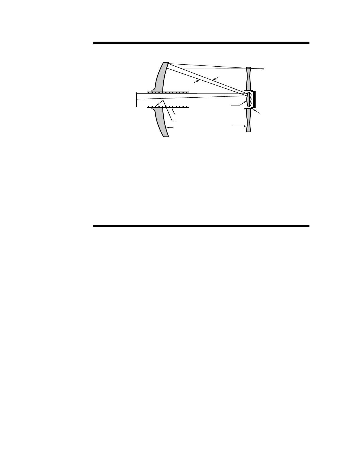
The Meade Schmidt-Cassegrain Optical System
In the Schmidt-Casseg
rain design of the Meade LX90, light enters from the right, passes through a thin lens with 2-sided
aspheric correction (“correcting plate”), proceeds to a spherical primary mirror, and then to a convex secondary mirror.The
convex secondary mirror multiplies the effective focal length of the primary mirror and results in a focus at the focal plane,
with light passing through a central perfor
ation in the primary mirror.
The Meade LX90 Schmidt-Cassegrain includes an oversize primary mirror of an 8.25" diameter, yielding a fully illuminated field-of-view significantly wider than is possible with a standard-size primary mirror. Note that light ray (2) in the figure
would be lost entirely, except for the oversize primary. It is this phenomenon which results in Meade Schmidt-Cassegrains
having off-axis field illuminations about 10% greater, aperture-for-aperture, than other Schmidt-Cassegrains utilizing standard-size primary mirrors. Field stops machined into the inside-diameter surface of the primary mirror baffle tube significantly increase lunar, planetary, and deep-space image contrast. These field stops effectively block off-axis stray light rays.

WARNING!
Never use a Meade®LX90™Telescope to
look at the Sun! Looking at or near the Sun
will cause instant and irreversible damage to
your eye. Eye damage is often painless, so
there is no warning to the observer that damage has occurred until it is too late. Do not
point the telescope at or near the Sun. Do
not look through the telescope or
SmartFinder as it is moving.
always have adult supervision while observing.
CAUTION: Use care to install batteries in the
orientation indicated by illustration in the battery slots of the battery holder. Follow battery
manufacturer's precautions. Do not install
batteries backwards or mix new and used
batteries. Do not mix battery types. If these
precautions are not followed, batteries may
explode, catch fire, or leak. Improperly
installed batteries void your Meade warranty.
If you are anxious to use your telescope
for the first time, read the QUICK-START
GUIDE on pages 4 and 5.
® The name "Meade," “AutoStar” and the Meade logo are
tr
ademarks registered with the U.S. Patent and Trademark
Office and in principal countries throughout the world.
“SmartFinder,” “Deep Sky Imager,” “LX90,” “LPI,” and
onight’s Best” are trademarks of Meade Instruments
“T
ation.
por
Cor
Patents:
US 6,304,376
US 6,392,799
US 6,563,636
D 422,610
Patent Pending.
© 2006 Meade Instr
uments Corporation.
Children should
CONTENTS
Quick-Start Guide .......................................................... 4
Telescope Features ...................................................... 6
To Attach the Handbox Holder.................................. 8
®
utoStar
A
Getting Started ..............................................................12
Parts Listing ..............................................................12
How to Attach the Tripod to the Telescope ..............12
Ho
Choosing an Eyepiece ..............................................14
Using SmartFinder ..................................................14
Aligning SmartFinder and the Viewfinder ................15
Observing ......................................................................16
Observing By Moving the Telescope Manually ........16
Terrestrial Observing ................................................16
Observing Using AutoStar's Arrow Keys ..................16
Slew Speeds ............................................................17
Observe the Moon ....................................................17
Astronomical Observing............................................18
To Track an Object Automatically ..............................18
Go To Saturn ............................................................20
Using the Guided Tour ..............................................20
Basic AutoStar Operation ..............................................22
AutoStar Navigation Exercise ..................................22
Entering Data into AutoStar ......................................23
Navigating AutoStar ..................................................23
Menus and Menu Options ..............................................24
Complete AutoStar Menu Structure..........................24
Objects Menu............................................................25
Event Menu ..............................................................26
Glossary Menu..........................................................26
Utilities Men
Setup Men
Advanced AutoStar Features..........................................31
Adding Observing Sites ............................................31
Finding Objects Not in the Database........................32
Obser
How to Create Your Own Guided Tour ......................34
Landmar
Identify ......................................................................38
Alternate Alt/Az Alignments ......................................38
Bro
Photography with the LX90 ............................................41
Optional Accessories......................................................43
Maintenance
Specifications ................................................................48
Appendix A:
Appendix B: Helpful Charts ............................................55
Appendix C: Training the Drive ......................................56
Appendix D:
eatures ........................................................ 9
F
w to Assemble Your Telescope ............................13
Alt/Az Home Position ..........................................18
Moving Through AutoStar’s Menus......................18
Automatic Alignment............................................18
Observe a Star Using Automatic Tracking ..........19
............................................................
u
..............................................................
u
ving Satellites
ks ................................................................37
......................................................................
wse
..................................................................
Collimation
Inspecting the Optics ..........................................47
Gauging the Movement of the Telescope ............47
Meade Customer Service....................................47
Equator
Basic Astronom
..................................................33
..........................................................45
olar) Alignment ......................50
ial (P
........................................
y
26
28
40
45
55

QUICK-START GUIDE
4
It is recommended that you attach the supplied tripod to the LX90 for observing. Perform the telescope and AutoStar
setup indoors in the light so that you become familiar with the parts and operation before moving the telescope
outside into the dark for observing.
1
1. Remove the field tripod from the shipping carton.
Stand the tripod vertically with the tripod feet
down and with the tripod still fully collapsed.
Grasp two of the tripod legs and, with the full
weight of the tripod on the third leg, gently pull the
legs apart to a fully open position.
2
4. Remove the spreader bar (see above figure) from
the shipping carton. Slide the spreader bar onto
the threaded rod and position the rod back
through the tripod head. Place the "C" clip into the
slot in the threaded rod – this clip holds the
threaded rod in place. Position the spreader bar so
that its three arms line up with the three tripod
legs.
2. Thread in two lock-knobs on each leg (six total)
near the foot of each tripod leg. Use the lockknobs to vary the height of the inner, extendible
tripod leg sections. Tighten the locks to a firm feel
only; do not overtighten.
Threaded
3
3. Remove the threaded rod (see above figure) from
Rod
ipod head.
the tr
threaded rod in place. Remove the small plastic
bag that is stapled to the threaded rod. This bag
contains the "C" clip retainer and an extra clip.
A small piece of plastic holds the
“C” Clip
5
Take the LX90 from its packaging and place the
5.
entire telescope onto the top of the tripod head,
inserting the threaded rod into the central hole in
e base of the telescope
the bottom of the dr
Tighten the tension knob (see abo
firm feel only; firm tightening of the tension knob is
sufficient to result in rigid positioning of the tripod
legs.
iv
ve figure) to a
.
4
R
ib
Battery
H
older
B
attery
C
ompartment
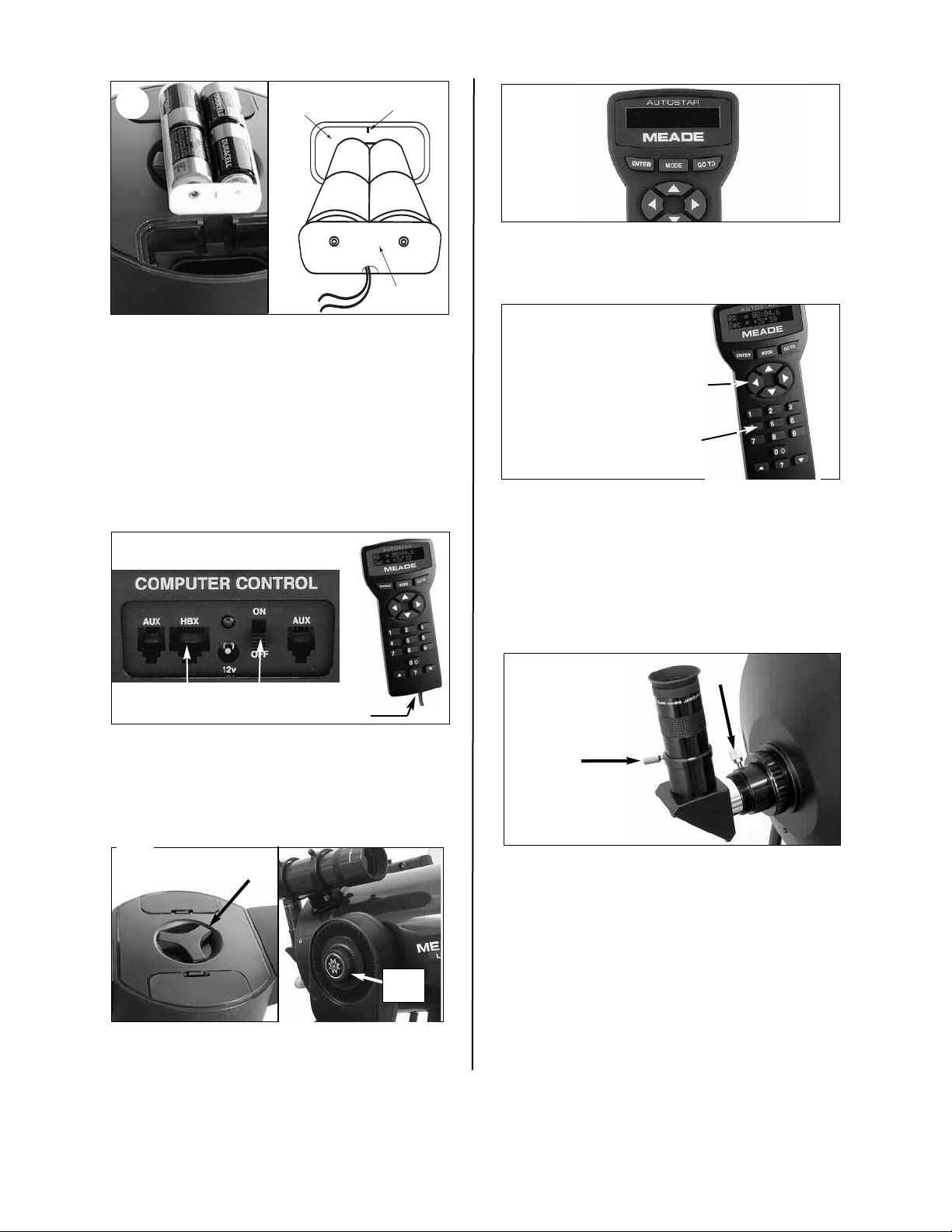
Remove the covers from both battery
(
c) 00 Meade [2.0]
A U T O S T A R
6
6.
compartments located on top of the drive base and
carefully lift the battery holders from their
compartments, being mindful of the connector
. Insert four (user-supplied) C-cell batteries
wires
into each battery holder (eight batteries total),
oriented as shown on the diagram on the battery
holder.
Return the battery holders to the battery
compartment. See the diagram above. Replace the
covers when you are done.
7
9
9. Flip the Power Switch on the computer control
panel to the ON position. The copyright message
lights on AutoStar’s LCD display.
J
10.
w Speeds:
Sle
Speed 9:
Speed 5:
Speed 1:
“Press 0 to align or Mode for Menu” displays. You
Fast
.
.
.
Medium
.
.
.
Slow
Arrow
Number
eys
K
eys
K
can use the Arrow keys to slew (move) the telescope up, down, right, or left. To change the telescope’s slew speed, press a Number key. "9" is the
fastest speed and "1" is the slowest speed. See
page 17 for more details. Or you can
begin Automatic Alignment.
See page 18 for more
Press “0” to
information.
HBX Port
ON/OFF
AutoStar Coil
Cable Port
7. Slide the computer control panel power switch to
OFF, if necessary. Remove the AutoStar handbox
and the AutoStar interface cable from the packing
materials. Plug one end into the HBX port of the
computer control panel and plug the other end into
the Coil Cable port on the AutoStar handbox.
R.A.
8
8. Tighten, to a firm feel only, the Dec and R.A. locks
Lock
Dec
k
Loc
(X and X, Fig. 1). Remove the dust cover from the
end of the telescope tube.
Thumb-
K
Thumbscre
11.
Remo
w
ve the dust cap from the rear cell of the
screw
telescope. Thread the eyepiece holder into the
rear cell thread.
epiece holder and loc
y
the e
Slide the diagonal pr
k in place b
the thumbscrew to a firm feel.
epiece into the
Place the Super Plössl 26mm e
diagonal pr
ism and tighten the attachment
y
thumbscrew to a firm feel only.
Sight along the side of the telescope’
s main tube
to locate an object. Use the telescope’s focus
knob (
8, Fig. 1) to bring the object into focus.
Practice using the AutoStar’s Arrow keys to center
an object in the telescope’
s field of vie
w.
ism into
y turning
5
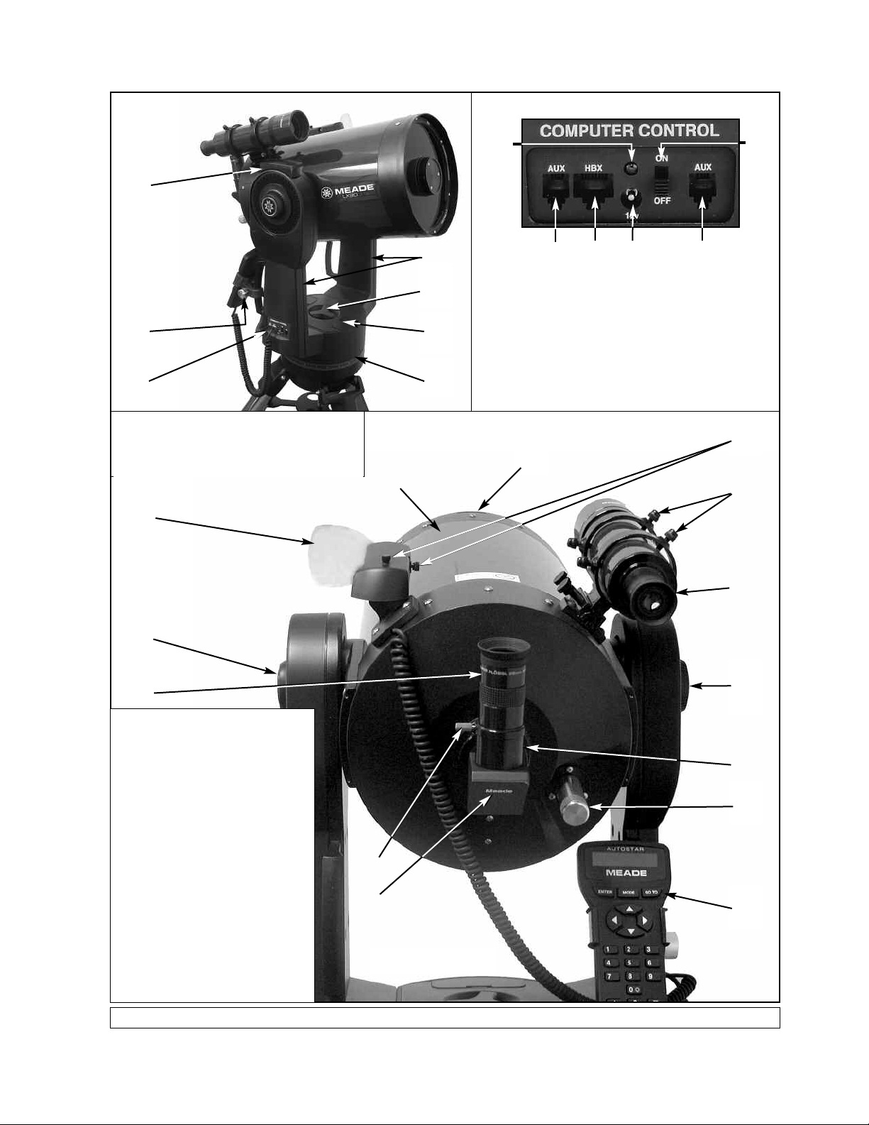
TELESCOPE FEATURES
Side View
1@
S
M
Some models of the LX90 have the computer
control panel on the left fork arm, others on
the right fork arm.
All models of the LX90 operate identically.
Q
5
7
9
P
J
B
A
D
A. Handbox Port
M
B. LED
C.
. Auxiliary Ports (2)
D
E. 12v Power Connector
E
ON/OFF Switch
Computer Control Panel
D
O
(not shown)
C
R
2!
K
A
1 Eyepiece
epiece Holder
Ey
2
3 Eyepiece Holder
4 Diagonal Prism
5
6 Dec. Lock
7 Fork Arms
8 Focus Knob
9 R.A. Lock
10 R.A. Setting Circle
11
12
13
14
15
16
17
18
19 Handbo
20 Viewfinder
21 Viewfinder Alignment Screws
Fig. 1: The LX90 Telescope and AutoStar Handbox.
T
Optical
Dec.
Setting Circle/Dec. Pointer
GPS Receiver
Computer Control Panel
utoStar handbox
A
Dust Co
y Compar
Batter
tFinder
Smar
tFinder Alignment Scre
Smar
x Holder
Thumbscre
ube
ver (not visible)
tment
w
2
D
ws
2)
6
3
8
N
Rear View
6

LX90: Your Personal Window to the Universe
The Meade LX90 is an extremely versatile, high-resolution telescopes with features similar to
those available only with larger and more specialized imaging systems. With pushbutton controls,
automatic tracking of celestial objects and software downloading capability, the LX90 telescope
may be all the telescope ever required by many terrestrial and astronomical observers.
epiece:Place the Super Plössl 26mm eyepiece into the eyepiece holder or 90° diagonal
1 Ey
prism (
4, Fig. 1) and tighten in place with the thumbscrews.The eyepiece magnifies the image
collected in the optical tube.
epiece Holder Thumbscrew:Tightens the eyepiece in place. Tighten to a firm feel only.
2 Ey
CAUTION:
Using products other
than standard Meade
accessories may
cause damage to the
telescope’s internal
electronics and may
void the Meade
warranty.
3 Eyepiece Holder: Holds the eyepiece in place.
4 Diagonal Prism: provides a more comfortable right angle viewing position. Slide the
diagonal prism directly into the eyepiece holder (
3, Fig. 1).
E Optical Tube: The main optical component that gathers the light from distant objects and
brings this light to a focus for examination through the eyepiece.
F Dec Lock: Controls the manual vertical movement of the telescope. Turning the Dec lock
counterclockwise unlocks the telescope enabling it to be freely rotated by hand about the
vertical axis. Turning the Dec lock clockwise (to a firm feel only) prevents the telescope from
being moved manually, but engages the vertical motor drive for AutoStar operation.
NOTE: The Dec lock knob is a knurled knob located on the fork arm to the right of the
focus knob (8, Fig. 1).
CAUTION: When loosening the Dec lock, be sure to support the optical tube
5, Fig. 1). The weight of the tube could cause the tube to swing through the fork arms
(
suddenly.
G Fork Arms: Hold the optical tube in place.
H Focus Knob:
precise image focus.The LX90 telescope can be focused on objects from a distance of about
25 ft. to infinity. Rotate the focus knob counterclockwise to focus on distant objects, and
clockwise to focus on nearby objects.
Moves the telescope’s primary mirror in a finely-controlled motion
to achieve
I R.A. Lock: Controls the manual horizontal rotation of the telescope. Turning the R.A. lock
counterclockwise unlocks the telescope, enabling it to be freely rotated by hand about the
horizontal axis. Turning the R.A. lock clockwise prevents the telescope from being rotated
manually, and engages the horizontal motor drive for AutoStar operation.
J Right Ascension (R.A.) Setting Circle: See APPENDIX A, page 50, for detailed
inf
or
mation.
le
es inf
c
(on left f
mation transmitted from Global Positioning System (GPS)
or
k ar
or
K Dec
lination (Dec)
ormation. Note the small, molded triangular pointer underneath the circle. Line up the
inf
desired Declination setting with this pointer.
Setting Cir
1@ GPS Receiver: Receiv
satellites. See page 21 for more information.
m):
See
APPENDIX A, page 50, f
or detailed
M Computer Control Panel
t
Handbo
A.
LED:The red po
B.
the AutoStar handbox and to the telescope’s motor drive.
ON/OFF Switc
C.
x (HBX) P
or
Plug the A
:
wer indicator light illuminates when power is supplied to
ns the Computer Control P
h
ur
T
:
utoStar coil cord (
anel and A
10,
) into this por
utoStar ON or OFF
2
Fig.
7
t.
.
. Auxiliary (AUX) Port (2)
D
and also current and future Meade accessories, such as the Meade Accessory Port
. See
Module
12v Power Connector:Provides connection so that the telescope assembly may
E.
be powered from either a 12v DC auto cigarette light plug or from a standard
115v AC home outlet using optionally available 25' power cords.
OPTIONAL ACCESSORIES, page 43.
vides connection for the SmartFinder LNT module,
:
Pro
N AutoStar: See page 9 for a description of AutoStar’s features.
O Dust Co
ver:Gently pry the dust cover from the front lens of the telescope.
TE:
NO
power turned off to the telescope. Verify that any dew that might have collected
during the observing session has evaporated prior to replacing the dust cover.
The dust co
ver should be replaced after each observing session and the
P Battery Compartments: Insert four (user-supplied) C-cell batteries in each compartment
(eight batteries total).
Q SmartFinder: Provides an easier way to sight on objects than the main telescope’s
eyepiece which has a narrow field of view. To assemble, see the SmartFinder addendum
sheet that is included with the manual.
R SmartFinder Alignment Screws: Adjust these screws to align the SmartFinder. See
pages 14 and 15 for more information.
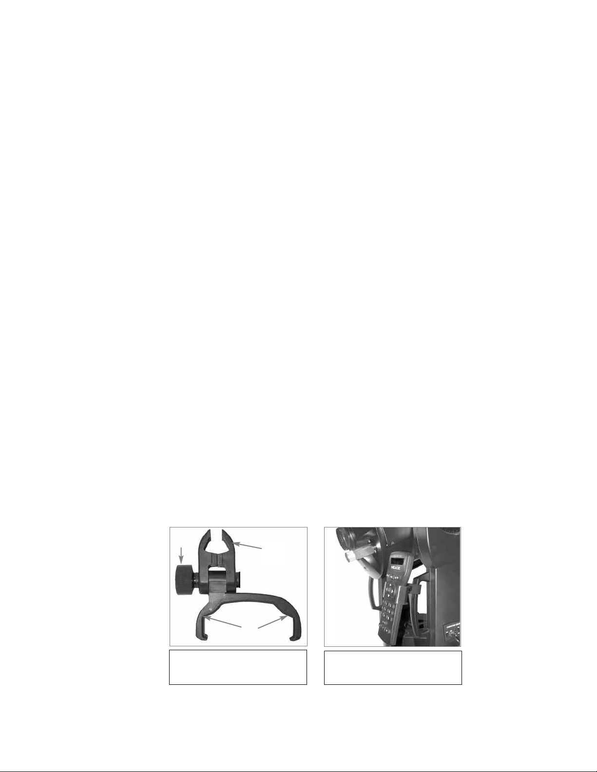
S Handbox Holder (refer to Figs. A and B below): Holds the AutoStar handbox in a
convenient position on the telescope fork arm handles.
T Viewfinder: A low-power, wide-field sighting scope with crosshairs that enable easy cen-
tering of objects in the telescope eyepiece.
2! Viewfinder Alignment Screws: Use these screws to adjust the alignment of the
viewfinder. See
To Attach the Handbox Holder:
1. Remove the handbox holder from the plastic bag.
2. If necessary, loosen the lock knob (
of the LX90 fork arm handles. Tighten the lock knob to a firm feel.
3 Slide the AutoStar handbox into the holder (
handbox into the holder: Slide one side of the handbox into the holder and then firmly press
the other side of the handbox into the holder until it snaps in place.
Adjust the tilt of of the holder by loosening the lock knob (
4.
holder clamp to the desired angle. Retighten the lock knob.
ALIGNING THE SMARTFINDER AND THE VIEWFINDER, page 15.
1, Fig. A) and place the clamp (2, Fig. A) on either one
3, Fig. A and Fig B). You may also snap the
Fig. A
1,
) and then mo
ving the
1
2
3
Fig. A: Handbox holder: (1) Lock
(2) Clamp;
knob;
(3) Holder.
Fig. B: Handbox holder attached to
fork arm handle. Adjust holder to a
venient tilt.
con
8
L
1
B
D
E
H
I
J
K
C
F
G
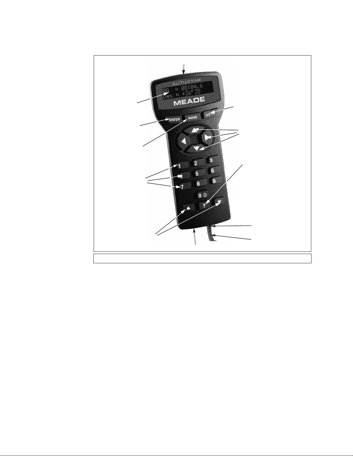
AUTOSTAR FEATURES
Fig. 2: The LX90 AutoStar Handbox.
Tour the Cosmos with Just the Push of a Button
Control of the LX90 is through the operation of the standard-equipment AutoStar. Nearly all
functions of the telescope are accomplished with just a few pushes of AutoStar’s buttons. Some
of the major features of AutoStar are:
• Automatically move the telescope to any of over 30,000 objects stored in the database or
manually enter the astronomical coordinates of any celestial object.
• Take a guided tour of the best celestial objects to view on any given night of the year.
wnload the latest satellite data and softw
Do
•
www.meade.com) and share software with other AutoStar enthusiasts.
(
Control y
•
• Access a glossary of astronomical terms.
• Calculate which eyepiece to use for optimum viewing of a celestial object.
Mount the telescope in the
•
fully automatic tr
Extensiv
•
the LX90 is mounted in the "Equator
our LX90 with y
king of celestial objects
ac
e long-e
xposure astrophotog
are revisions directly from the Meade website
our PC using an RS-232 interf
“Alt/Az”
mode (Altitude - Azim
.
y and CCD imaging capability is a
aph
r
olar) mode using an optional mounting w
ial" (P
ace
.
uth, or v
ertical - horizontal) for
ailable when
v
edge.
9

NOTE:
AutoStar does not
require batteries; the
telescope’s batteries
supply power to
AutoStar.
NOTE:
Throughout this
manual, you will notice
the term "Alt/Az." Alt/Az
is frequently used to
refer to Altitude
(vertical) and Azimuth
(horizontal). Alt/Az is
just one of many
methods used by
amateur astronomers to
help locate stars in the
night sky.
TIP:
To manually enter the
R.A. and Dec
coordinates of an
object:
Press and hold MODE
for two seconds or more.
The R.A. and Dec coordinates display. Press
GO TO. "Object Position"
and a set of coordinates
displays. Then enter the
R.A. and Dec
coordinates of any
celestial object using
Number keys. As soon
as the coordinates are
entered, A
the telescope to the
coordinates
the telescope m
initialized for this
procedure to operate
properly.
utoStar sle
. Note that
ws
ust be
utoStar Computer Controller provides control of virtually every telescope function within
The A
a compact handbox. AutoStar has soft-touch keys designed to have a positive feel. The LCD
(Liquid Cr
ystal Display) is backlit with a red LED (Light Emitting Diode) for easy viewing in the
dark. The backlit display, key arrangement, and sequential database make AutoStar extremely
iendly.
user fr
y:
1 2-Line LCD Displa
•
Top line: Lists the primary category or menu item.
• Bottom line: Contains a men
vides an interface between AutoStar and the telescope.
Pro
u option or information about an object or subject,
depending on which function is being performed.
2 ENTER Key: Accesses, in a sequential manner, the next menu or data level in the AutoStar
database. See
OPTION DESCRIPTIONS,
NOTE: If ENTER is pressed for two seconds or more and then released, AutoStar
emits a beep and “ENTER to Sync” is displayed. "ENTER to Sync" is relevant only
after the telescope has been aligned and is pointing at an object. If the "ENTER to
Sync" feature is accessed by mistake, press MODE to return to the previous
screen.
MOVING THROUGH AUTOSTAR'S MENUS, page 18 and MENU AND MENU
page 24.
See HIGH PRECISION, page 29, for more details about this feature.
3 MODE Key: Returns to the previous menu or data level in the AutoStar database until the
top level, “Select Item," is reached. The MODE key is similar to the ESCAPE key on a
computer.
NOTE: Pressing MODE while in the “Select Item” level moves AutoStar to the
topmost screen: “Select Item: Object.”
If MODE is pressed and held for two seconds or more, information about the
telescope's status displays. When the status displays, press one of the Scroll keys
7, Fig. 2) to display the following information:
(
• Right Ascension and Declination (astronomical) coordinates
• Altitude (vertical) and Azimuth (horizontal) coordinates
• Local Time and Local Sidereal Time (LST)
• Timer and Alarm Status
• Accessory Port Module (APM) status (see the instructions supplied with the APM)
• Date
• Site coordinates
• Battery status
• SmartFinder Finder Set menu (see below)
Press MODE again to return to the previous menu.
Finder Set menu:Select the Finder Set men
intensity and blink rate of the SmartFinder red dot.
To set the blink rate of SmartFinder’s red dot (circled numbers refer to Fig. 2):
1. Press and hold MODE c for two seconds. R.A and Dec. coordinates display.
2. Keep pressing the Scroll Down key h until “Finder Set: Set” displays.
3. Press ENTER b. “Finder Set: Intensity” displays.
4.
Press the Scroll Do
5. Press ENTER
wn key
b. A time value, in seconds, displays. For example, “00.5” may
h.
“Finder
display. “00.5” (one-half second) is the amount of time, in seconds, that the red dot will blink
”
“on.
6. Use the Number keys g and the Arrow keys f to change the time value. For example,
y wish to change the amount of time the red dot sta
ou ma
y
y
e
press the Right Arro
”
“1,
nate method is to use the Scroll k
alter
alue is entered, press ENTER
time v
w k
f, press
7. Press the Scroll Down key h. “Finder: Blink Off” displays. Press ENTER b. A time value,
(one-tenth second), ma
“00.1”
of time the red dot sta
alues are already z
o v
first tw
y displa
ys off to 00.7 seconds:
, then press “7.” Or you may use the Scroll keys
ero)
through the time values.
u to access options that will allow you to set the
: Blink On” displays.
ys on to 10.2 seconds:
y
e
press the Right Arro
”
“0,
ys
e
h to scroll through the time v
w k
f, press
alues
b.
ou may wish to change the amount
, y
xample
or e
F
.
y
y
e
Press the Right Arro
w k
f twice
Press
An
”
“2.
Once the
.
(as the
h to scroll
10

The SmartFinder’s red dot will now blink on for 10.2 seconds and turn off for 0.7 seconds,
8.
and then repeat the cycle until you change the values again. Press and hold MODE c to
exit this function.
ly, you can set the Intensity value by scrolling through the intensity values with the Scroll
Similar
keys h. The Intensity option lets you select a value of intensity for the red dot from 0 (Off) to
14 (Full Intensity).
4 GO
TO Key:Slews (moves) the telescope to the coordinates of the currently selected
object. While the telescope is slewing, the operation may be aborted at any time by
pressing any key except GO TO. Pressing GO TO again resumes the slew to the object.
5 Arrow Keys: Slew the telescope in a specific direction (up, down, left, and right), at any
one of nine different speeds. Speed selection is explained in
following functions are also available with the Arrow keys:
• Data entry - Use the Up and Down Arrow keys to scroll through the letters of the
alphabet and numerical digits. The Down Arrow key starts with the letter "A" and
the Up Arrow key starts with the digit "9." The Left and Right Arrow keys are used
to move the blinking cursor left and right across the LCD display.
Moves the telescope - Use the Up and Down Arrow keys to move the telescope
•
vertically up and down. The Left Arrow key rotates the telescope horizontally
counterclockwise, while the Right Arrow key rotates it clockwise.
SLEW SPEEDS, page 17. The
6 Number Keys: Input digits 0 - 9 and changes the slew speeds (see SLEW SPEEDS, page
17). The "0" key also turns on and off the red utility light on the top of the handbox.
7 Scroll Keys: Accesses options within a selected menu. The menu is displayed on the first
line of the screen. Options within the menu are displayed, one at a time, on the second line.
Press the Scroll keys to move through the options. Press and hold a Scroll key to move
quickly through the options.
The Scroll keys also scroll through the letters of the alphabet and numerical digits.
NOTE: The Scroll Down key and the Down Arrow key move forward through the
alphabet & digits (A to Z, 0 to 9). The Scroll Up key and the Up Arrow key move
backward (Z to A, 9 to 0). Common symbols are also available in the list.
8 ? Key: Accesses the "Help" file. "Help" provides on-screen information on how to
accomplish whatever task is currently active.
Hold down the ? key and then follow the prompts on the display to access details of
AutoStar functions in the Help feature. The Help system is essentially an on-screen
instruction manual.
If you have a question about an AutoStar operation,
hold down the ? key and follow the directions that scroll on the second line of the LCD
screen. When a word appears in [brackets], press ENTER to access the AutoStar
Glossary. A definition or more detailed information is displayed. Press MODE to return to
the scrolling AutoStar Help display.
When satisfied with the Help provided, press MODE to return to the original screen and
continue with the chosen procedure.
e.g., INITIALIZATION, ALIGNMENT, etc.,
I Coil Cord Port: Plug one end of the AutoStar coil cord into this port (11, Fig. 2) located at
the bottom of the AutoStar handbox.
J Coil Cord: Plug one end of the AutoStar coil cord into the HBX port (13A, Fig. 1) of the
computer control panel of the telescope and the other end into the coil cord port (see
j above).
K RS-232 Port: plug an RS-232 cable into AutoStar for downloading functions such as
"Download" or "Clone." See page 30 for more details.
L Utility Light: Use this built-in red light to illuminate star charts and accessories without
disturbing your eye's adaptation to darkness.
11
GETTING STARTED
Getting the telescope ready f
opening the packing box, note carefully the following parts:
• LX90 Telescope with fork mount system and attached SmartFinder
• AutoStar handbox and interface coil cord
• Eyepiece holder and 1.25” diagonal prism
• 8 x 50 Viewfinder
Super Plössl 26mm eyepiece
•
• Variable height tripod and mounting base
• Set of hex wrenches and a plastic bag containing a “C” clip and a washer
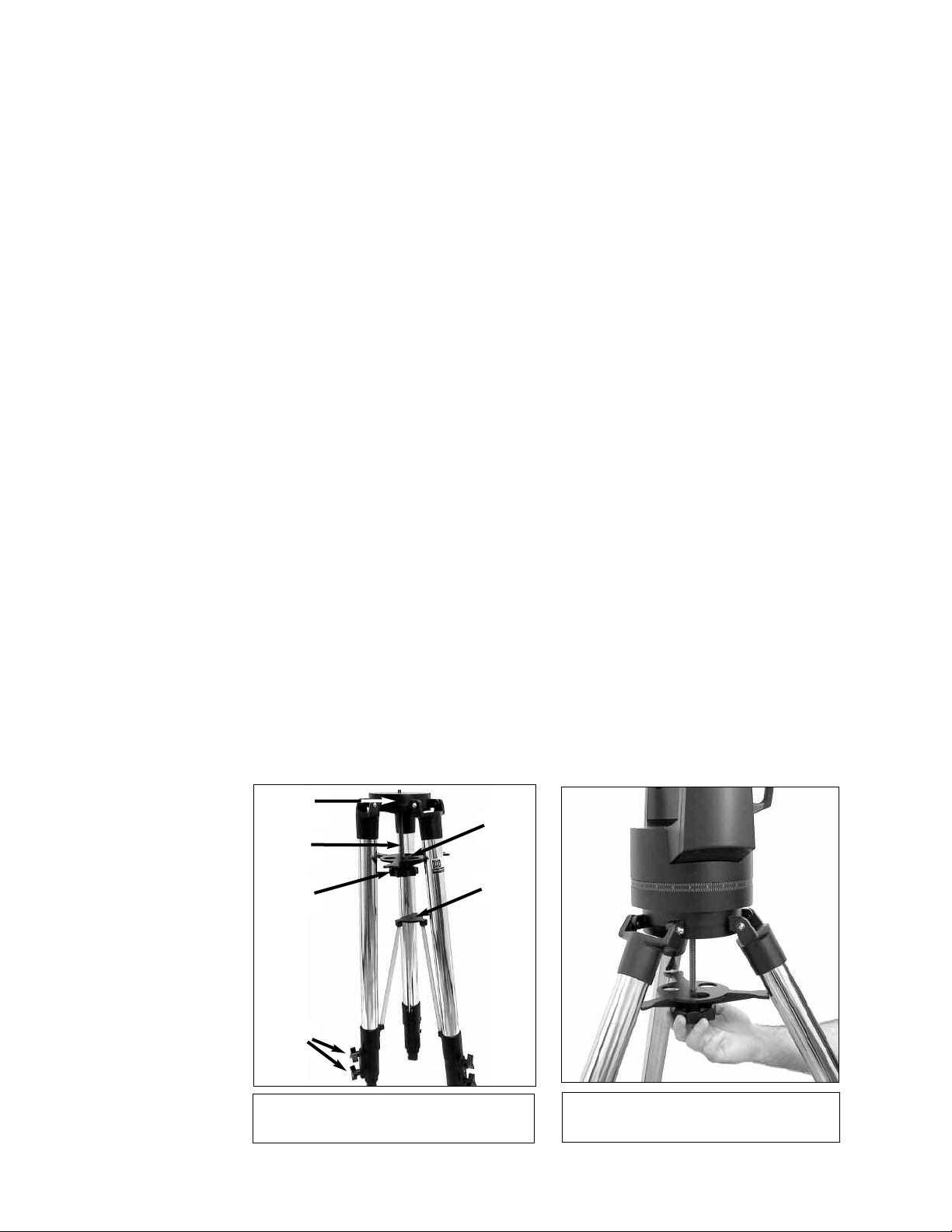
How to Attach the Tripod to the Telescope Assembly
The telescope’s fork mount attaches directly to the field tripod. The telescope in this way is
mounted in an
this configuration moves along vertical and horizontal axes, corresponding respectively to the
Declination (vertical) and Right Ascension (horizontal) axes in an astronomical observing mode.
The field tripod also can be used in conjunction with the optional equatorial wedge (see
EQUATORIAL WEDGE, page 52) for long exposure astrophotography. The equatorial wedge per-
mits alignment of the telescope’s Polar Axis with the Celestial Pole (or North Star).
1. After removing the field tripod from its shipping carton, stand the tripod vertically, with the
tripod feet down and with the tripod still fully collapsed (
pod legs and, with the full weight of the tripod on the third leg, gently pull the legs apart to
a fully open position.
2. Thread in the 6 lock-knobs (2 on each tripod leg) near the foot of each tripod leg (Fig. 3).
These lock-knobs are used to fix the height of the inner, extendible tripod leg sections.
NOTE: Tightening to a firm-feel is sufficient; over-tightening may result in stripping
of the knob threads or damage to the tripod legs and results in no additional
strength.
3. The spreader bar (4, Fig. 3) has been removed for shipment. To install, first remove the
threaded rod (
threaded rod in place. Remove the small plastic bag that is stapled to the threaded rod.
This bag contains the “C” clip retainer and an extra clip.
4. Slide the washer followed by the spreader bar onto the threaded rod (note the correct orientation as shown in
Place the clip retainer ( a “C” clip) into the slot in the threaded rod.This clip holds the threaded rod in place. See
5. Position the spreader bar so that the 3 arms of the spreader bar line up with the 3 tripod
legs.
“Altazimuth” (“Altitude-Azimuth,” or “vertical-horizontal”) format. The telescope in
2, Fig.3) from the tripod head (1, Fig. 3); a small piece of plastic holds the
or first observations requires only a few minutes. When first
see Fig. 3). Grasp two of the tri-
Fig. 4) and position the threaded rod back through the tripod head.
Fig. 3.
1
2
3
5
Fig. 3: Field Tripod. (1) Tripod Head;
(2) Threaded Rod; (3) Tension Knob;
(4) Spreader Bar; (5) Lock Knobs;
4
6
Fig. 4: Attaching the telescope to the tripod.
Note the orientation of the spreader bar.
12
Place the entire telescope onto the top of the tripod head, and insert the threaded rod into
Rib
Battery
Holder
Battery
Compartment
6.
the centr
(
3,
tr
al hole in the bottom of the drive base of the telescope. Tighten the tension knob
Fig. 3);firm tightening of the tension knob is sufficient to result in rigid positioning of the
ipod legs.
7. To vary the tripod height, loosen the 6 lock-knobs, slide the 3 inner tripod leg sections out
to the desired height, and firmly re-tighten (but do not overtighten) the 6 lock-knobs.
To collapse the tripod (after removing the telescope and equatorial wedge, if applicable) for
storage follow these steps:
1. Rotate the spreader bar 60° from its assembled position, so that one spreader bar arm is
located between each adjacent pair of tripod legs.
2. At the base of the tripod is a 3-vane extension strut system, with a circular hub at its
center (
6, Fig. 3). Grasp the tripod head (1, Fig. 3) with one hand and, with the other hand,
pull directly “up” on the central hub of the extension strut system. This operation will cause
the tripod legs to move inward to a collapsed position.
Precautionary notes for the tripod
• If the tripod does not seem to extend or collapse easily, do not force the tripod legs in or
out. By following the instructions above, the tripod will function properly, but if you are
unclear on the proper procedure, forcing the tripod into an incorrect position may damage
the extension strut system.
• Be sure the spreader bar (
4, Fig. 3) is not upside-down on the threaded rod.
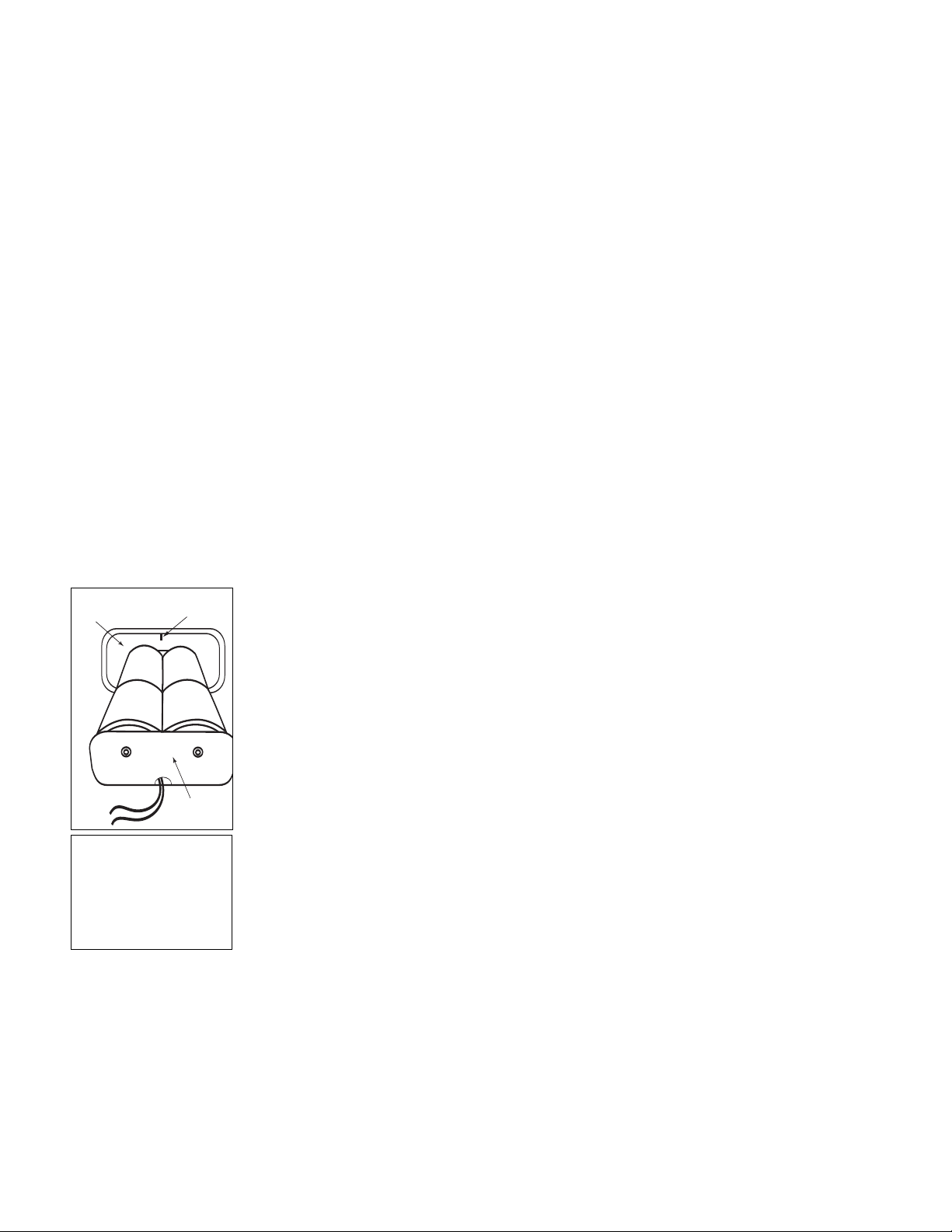
How to Assemble Your Telescope
Assembly of the LX90 telescope requires eight C-cell (user-supplied) batteries or optional
power cords (25') to a standard 115v home outlet or to a 12v DC automobile cigarette lighter
plug. See the Instruction Sheets supplied with the optional power cords for installation
information. To install batteries:
1. Unlock the Dec lock (
the optical tube to the position depicted in
2. Remove the battery compartment covers (
holder, being mindful of the connector wires. Insert four C-cell batteries into each battery
holder, oriented as shown on the diagram on the battery slots inside the battery holder.
Return the battery holders to their respective compartments and replace the covers.
Fig. 5 for the proper orientation of the holder. Do not force the holder into the battery
See
compartment. If a holder does not slip easily into the compartment, you may have
inserted the holder incorrectly. Replace the compartment covers when you are done.
CAUTION: Use care to install batteries as indicated by the battery compartment.
Follow battery manufacturer's precautions. Do not install batteries backwards or
mix new and used batteries. Do not mix battery types. If these precautions are not
followed, batteries may explode, catch fire, or leak. Improperly installed batteries
v
oid your Meade warranty. Always remove the batteries if they are not to be used
for a long period of time.
6, Fig. 1) to move the optical tube (5, Fig. 1) through the fork arms. Move
Fig. 1 (top image) and relock the Dec lock.
16, Fig. 1) and carefully remove the battery
Fig. 5: Four C-cell
batter
ies mounted inside
one of the batter
Note position of rib in the
y compar
batter
y holders .
tment.
3. Be certain that the power switch on the computer control panel (13C, Fig. 1) is in the OFF
position. Plug the SmartFinder coil cord into one of the AUX ports (
13D, Fig. 1) on the
computer control panel. Plug the coil cord of the AutoStar Controller into the HBX port
13A, Fig. 1).
(
TE:AutoStar does not require batteries; the telescope’s batteries supply power
NO
to A
utoStar.
4. Remove the dust cap from the rear cell of the telescope. Thread the eyepiece holder into
epiece holder and lock in place by
the rear cell thread.
Slide the diagonal pr
ism into the e
y
turning the thumbscrew to a firm feel.
5. Remove the Super Plössl 26mm eyepiece (
diagonal prism (
Remo
6.
ve the dust cover (
3, Fig. 1). Tighten the thumbscrew (2, Fig. 1) to a firm feel only.
1
Fig.
15,
) from the optical tube assemb
1, Fig. 1) from its container and place it in the
ly (5,Fig.
1
) b
y gently
prying it off.
13

NEVER point the
telescope directly at
or near the Sun at
any time! Observing
the Sun, even for the
smallest fraction of a
second, will result in
instant and
irreversible eye damage, as well as
physical damage to
the telescope itself.
NOTE:
For a list of magnification ratings of the eyepieces available for
the LX90 telescope,
OPTIONAL
see
ACCESSORIES
43.
, page
Choosing an Eyepiece
A telescope’s eyepiece magnifies the image formed by the telescope’s main optics. Each
eyepiece has a focal length, expressed in millimeters, or “mm.” The smaller the focal length, the
higher the magnification. For example, an eyepiece with a focal length of 9mm has a higher
magnification than an eyepiece with a focal length of 26mm.
our telescope comes supplied with a Super Plössl 26mm eyepiece, which gives a wide,
Y
comfortable field of view with high image resolution.
Low power eyepieces offer a wide field of view, bright, high-contrast images, and eye relief
during long observing sessions. To find an object with a telescope, always start with a lower
power eyepiece such as the Super Plössl 26mm. When the object is located and centered in
the eyepiece, you may wish to switch to a higher power eyepiece to enlarge the image as much
as practical for prevailing seeing conditions. For information about optional eyepieces for the
LX90, see
OPTIONAL ACCESSORIES, page 43.
NOTE: Seeing conditions vary widely from night-to-night and site-to-site. Turbulence
in the air, even on an apparently clear night, can distort images. If an image
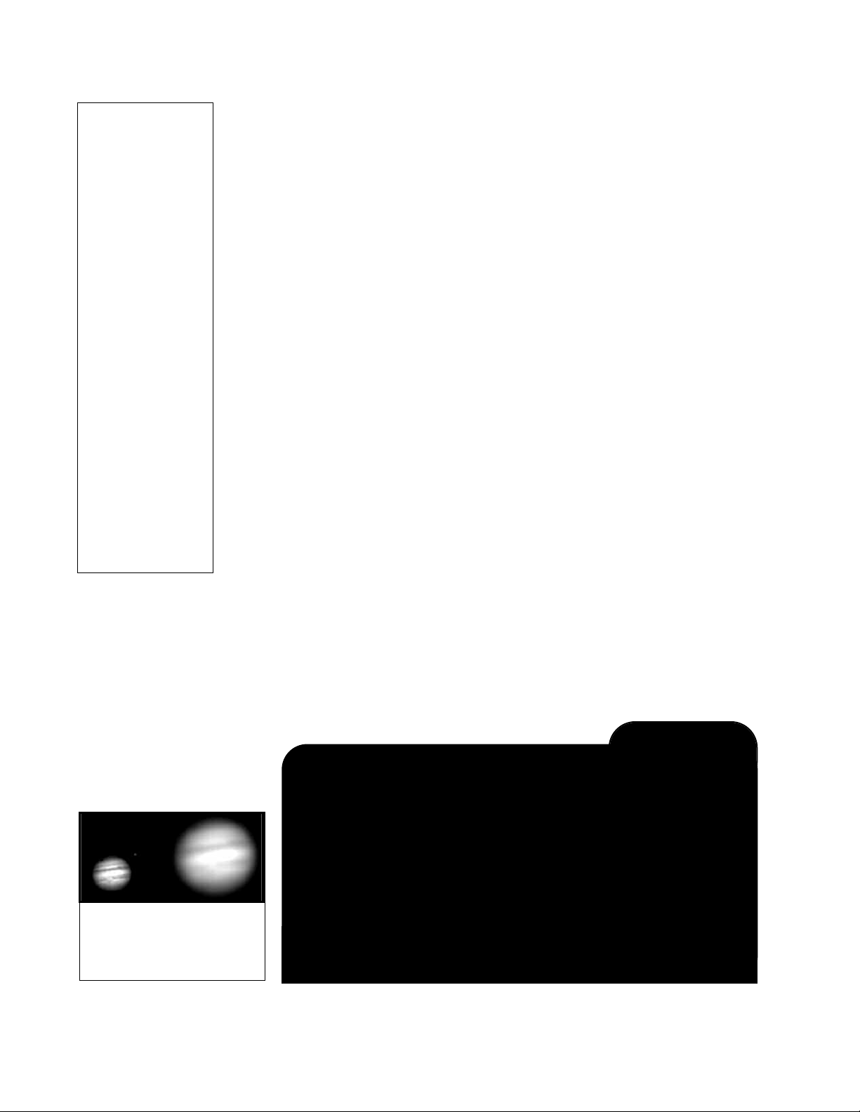
appears fuzzy and ill-defined, back off to a lower power eyepiece for a more wellresolved image (
Fig. 8a and 8b).
The power or magnification of a telescope is determined by the focal length of the telescope
and the focal length of the eyepiece being used. To calculate eyepiece power, divide the
telescope's focal length by the eyepiece's focal length. For example, a 26mm eyepiece is
supplied with the LX90. The focal length of the 8” LX90 is 2000mm (see
SPECIFICATIONS, page
48).
Telescope Focal Length 2000mm
Eyepiece Focal Length 26mm
2000 ÷ 26 = 77≠
The eyepiece power, or magnification, is therefore 77X.
Using SmartFinder
As with most astronomical telescopes, an eyepiece presents a narrow field of view to the
observer. As a result it is sometimes difficult to locate objects just using your eyepiece. The
SmartFinder has a projected red dot that helps you to locate objects as you move your
telescope. See page 10 for more information about the SmartFinder’s Finder Set menu.
To turn on SmartFinder’s red dot (continuous, without blinking):
1. Press and hold AutoStar’s MODE key for two seconds. R.A and Dec. coordinates
display.
2. Keep pressing the Scroll Down key until “Finder Set: Set” displays.
3. Press ENTER. “Finder Set: Intensity” displays.
4. Press ENTER. “Finder: Blink On” displays.
5. Press Scroll Down key. A time value, in seconds, displays. For example, “00.5” may
is the amount of time, in seconds, that the red dot will blink “on.”
“00.5”
.
y
displa
(For this example, you may select or enter any value except “00.0.”) Press ENTER.
6. Press Scroll Down key“Finder: Blink Off” displays.
ys to enter “00.0” or press the Scroll Down
Press ENTER.
7.
Use the Number k
key until “00.0” displays. “00.0” is the amount of time in seconds that the
red dot will remain “off.” This value, along with the value you chose in the
“Finder: Blink On” menu, allows the red dot to remain on without blinking.
means there is no “off” time, so the dot will remain on continuously,
“00.0”
without blinking.
Use these men
8.
the Blink On men
or .2 seconds and then b
f
us to set other b
“00.1” in the Blink Off menu, the red dot will blink on
u, and
link off f
you change the values again.
9. Press and hold MODE to exit this function.
k this alignment on a celestial object, such as the Moon or a bright star, and make
Chec
any necessary refinements to the intensity and blink rate, using the method outlined
above.
e
For example, If you select “00.2” in
.
ates
link r
or .1 second, and then repeat the cycle until
14
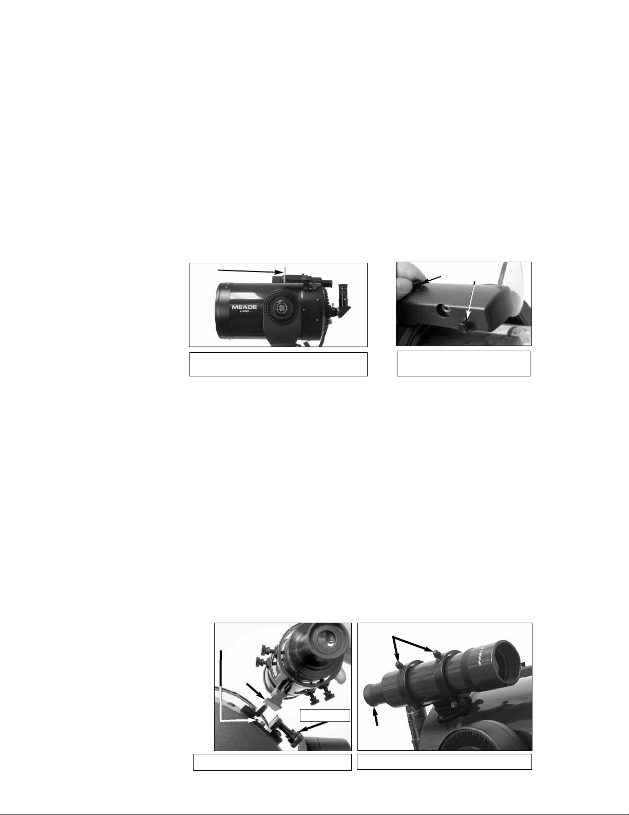
Aligning SmartFinder
In order f
that both the SmartFinder and the main telescope are pointing at precisely the same location.
o align the SmartFinder:
T
1. Point the main telescope at some well-defined distant (perhaps a mile away) land object,
2.
The SmartFinder is now aligned to the main telescope. Unless the alignment screws are
disturbed or the LNT Module is moved out of place, the SmartFinder should remain aligned
indefinitely.
or the SmartFinder to be useful, it must first be aligned with the main telescope, so
such as a telephone pole or sign. Center the object, as precisely as possible, in the SP
26mm eyepiece's field of view. Tighten the vertical and horizontal locks (
6 and 9, Fig. 1) so
that the tube cannot move and the object remains centered.
While looking through the SmartFinder (1,Fig. 6
n the top or side alignment screws (
), tur
and 3, Fig. 7), until the red dot of the SmartFinder points at precisely the same position as
w through the eyepiece of the main telescope.
the vie
2
A
Fig. 6a: SmartFinder Location.
Fig. 6b: Turn the top (2) or side
(3) SmartFinder.
B
C
Aligning the Viewfinder
Like the SmartFinder, the viewfinder helps you locate objects and must also be aligned to the
main telescope. To align the viewfinder, perform steps 1 through 5 during the daytime; perform
step 6 at night.
1. Slide the track on the bottom of the viewfinder into the slot in the viewfinder mounting
assembly. See
thumbscrews (
2. If you have not already done so, insert the Super Plössl 26mm eyepiece into the diagonal
prism.
3. Unlock the R.A. (
both axes.
4. Point the telescope at some well-defined and stationary land object at least 200 yards distant, such as the top of a telephone pole or street sign.
eyepiece. Re-tighten the R.A. and Dec locks.
5. Look through the viewfinder eyepiece (
or more of the vie
cisely centered on the object you previously centered in the telescope eyepiece.
6. Check this alignment on a celestial object, such as the Moon or a bright star, and make any
necessary refinements, using the method outlined in steps 3 and 4.
Mounting
Slot
Fig. 7a. To secure the viewfinder to the mounting assembly, tighten the two
Fig. 7a) to a firm feel only.
9, Fig. 1) and Dec (7, Fig. 1) locks so that the telescope moves freely on
Center the object in the telescope
Fig. 7b) and loosen or tighten, as appropriate, one
wfinder alignment screws (
Fig.7b) until the vie
Alignment
Screws
wfinder crosshairs are pre-
Fig.
Tr ac k
wfinder Assemb
Vie
7a:
Thumbscrews
ly.
15
Viewfinder
Eyepiece
7b:
Fig.
wfinder Assemb
Vie
ly.
IMPORTANT NOTE:
Objects appear
upside-down and
reversed left-for-right
when observed in the
eyepiece when inserted directly into the
(straight-through) eyepiece holder – with the
diagonal prism in
place, images will be
right-side-up, but
reversed left-for-right.
This image inversion is
of no consequence
when observing
astronomical objects
and, in fact, all astronomical telescopes
yield inverted images.
During terrestrial
observing, where a
fully-correctly-oriented
image (right-side-up
and correct left-forright) is desirable, an
optional #928 45°
Erecting Prism is
available. See
OPTIONAL
ACCESSORIES,
43.
page
OBSERVING
Observing By Moving the Telescope Manually
If you wish to observe a distant land object, such as a mountain top or a bird, you can observe
by merely pointing the telescope and looking through the eyepiece.
1. Loosen the telescope’s R.A. lock (
2. Move your telescope to observe distant street signs, mountains, trees, and other
structures. Use SmartFinder and/or the viewfinder to to help site-in on an object.
3. Center the object with SmartFinder’s red dot and then in the telescope eyepiece.When the
object is
centered in your eyepiece, remember to re-tighten the R.A. and Dec locks.
4. Practice focusing objects with the focus knob (
5. Once you get a feel for how your telescope moves and focuses, try to view something more
challenging, like a bird or a distant moving train.
NOTE: Viewing conditions vary widely from night-to-night and site-to-site.
Turbulence in the air, even on an apparently clear night, can distort images. Lowpower eyepieces, such as the Super Plössl 26mm supplied with your telescope, are
better suited to resolving images in poor viewing conditions.
You can also observe stars and objects in the night sky using this method, but note that objects
begin to slowly drift across the eyepiece field.This motion is caused by the rotation of the Earth.
As you become familiar with the AutoStar handbox operation, you can counteract the drift using
the automatic tracking feature in the AutoStar Setup menu (see
AUTOMATICALLY, page 18), or by using AutoStar's GO TO capabilities (see GO TO
SATURN, page 20).
Terrestrial Observing
The LX90 ia an excellent high-resolution, terrestrial (land) telescopes. Viewing terrestrial
objects requires looking along the Earth's surface through heat waves.These heat waves often
cause degradation of image quality. Lower power eyepieces, like the Super Plössl 26mm
eyepiece, magnify these heat waves less than higher power eyepieces. Therefore, lower power
eyepieces provide a steadier, higher quality image. If the image is fuzzy or ill-defined, reduce
to a lower power eyepiece, where the heat waves do not have such an effect on image quality.
Observing in early morning hours, before the ground has built up internal heat, produces
better viewing conditions than during late afternoon hours.
9, Fig. 1) and Dec lock (6, Fig. 1).
8, Fig. 1).
TO TRACK AN OBJECT
Observing Using AutoStar's Arrow Keys
You may observe land and astronomical objects using AutoStar's Arrow keys to move the
telescope.
1.
Fig. 8a & 8b: Jupiter:
Examples of the right
amount of magnification and
too much magnification.
Tighten the Dec and R.A.
er ha
v
ou e
Can y
epiece magnification, yes, you can! The
y
e
beginning observer is to “overpower” a telescope by using high magnifications
which the telescope and atmospheric conditions cannot reasonably support.
Keep in mind that a smaller, but bright and well-resolved image is far superior to
one that is larger, but dim and poorly resolved (see Figs. 8a and 8b). Powers
ve 400X should be employed only under the steadiest atmospheric
abo
conditions.
utoStar can calculate the best e
A
Calc” feature in the Utilities menu.
ers should ha
Most obser
ange of reasonable magnifications possible with the
r
OPTIONAL ACCESSORIES, page 43.
v
loc
ks (
6 and 9,
Fig.
1
).
LX90 TIPS
oo Much Power?
T
e too much power? If the type of power you’re referring to is
v
most common mistakeof the
epiece for you to use. Try out the “Eyepiece
y
e three or four additional eyepieces to achieve the full
v
LX90 telescopes
. See
16

Verify that AutoStar is properly connected to your telescope. See
2.
TELESCOPE,
page 13.
HOW
TO ASSEMBLE YOUR
3. Flip the telescope power switch to the ON position.
The AutoStar screen is activated and a copyright message displays briefly, followed by a
short beep. Then AutoStar takes a few moments to start up the system.
Mode for Menu” displays (if you select "0" automatic Alignment will begin).
The Arrow keys are now activated. Press the Arrow keys (5,Fig. 2
4.
“Press 0 to align or
w (move) the
) to sle
telescope up, down, right, or left.
5. Press a Number key (8, Fig. 2) to change the telescope’s slew speed. See SLEW SPEEDS,
below, for more information.
6. Use SmartFinder (
17, Fig. 1) and/or the viewfinder (1, Fig. 20) to locate an object and prac-
tice using the AutoStar’s Arrow keys to center the object in the telescope’s field of view.
7. Use the telescope’s focus knob (8, Fig. 1) to bring the object into focus.
Slew Speeds
AutoStar has nine slew speeds that are directly proportional to the sidereal rate and have been
calculated to accomplish specific functions. Pressing a Number key changes the slew speed,
which is shown for about two seconds on AutoStar’s display.
The nine available speeds are:
Number Key 1 = 1x = 1 x sidereal (0.25 arc-min/sec or 0.004°/sec)
Number Key 2 = 2x = 2 x sidereal (0.5 arc-min/sec or 0.008°/sec)
Number Key 3 = 8x = 8 x sidereal (2 arc-min/sec or 0.033°/sec)
Number Key 4 = 16x = 16 x sidereal (4 arc-min/sec or 0.067°/sec)
Number Key 5 = 64x = 64 x sidereal (16 arc-min/sec or 0.27°/sec)
Number Key 6 = 128x = 32 arc-min/sec or 0.5°/sec
Number Key 7 = 1.5° = 90 arc-min/sec or 1.5°/sec
Number Key 8 = 3° = 180 arc-min/sec or 3°/sec
Number Key 9 = Max = 390 arc-min/sec or 6.5°/sec)
NOTE:
Do not look through the
telescope's eyepiece or
wfinder while it is
vie
rapidly moving. Children
should always have
adult supervision while
observing.
Speeds 1, 2, or 3: Best used for fine centering of an object in the field of view of a higher power
eyepiece, such as a 12mm or a 9mm eyepiece.
Speeds 4, 5, or 6: Enables centering an object in the field of a low-to-moderate power
epiece
y
e
, such as the standard Super Plössl
26mm.
Speeds 7 or 8: Best used for rough centering of an object in the eyepiece.
Speed 9: Mo
es the telescope quic
v
kly from one point in the sky to another
Observe the Moon
Point your telescope at the Moon (note that the Moon is not visible every night) and practice
using the Arrow keys and the slew speeds to view different features. The Moon contains many
interesting features, including craters, mountain ranges, and fault lines. The best time to view
the Moon is during its crescent or half phase. Sunlight strikes the Moon at an angle during these
periods and adds a depth to the view. No shadows are seen during a full Moon, causing the
ight surf
ly br
er
v
o
ace to appear flat and r
ather uninteresting.
density Moon filter when observing the Moon. Not only does it cut down the Moon's bright glare,
ut it also enhances contrast, providing a more dramatic image.
b
Consider the use of a neutral
17

Definition:
Initialization
cedure that ensures
that A
correctly
first use AutoStar, it
doesn't yet know
where the observation
location site is or the
time or date of the
observation session.
During the
alignment procedure,
the system calculates
these parameters
automatically.
AutoStar uses this
information to precisely calculate the location of celestial objects
(such as stars and
planets) and to move
your telescope correctly for various operations.
Impor
Press any key on the
utoStar handbo
A
t the GPS fix.
abor
Press MODE repeatedly until "Select Item"
displays and use the
AutoStar menu options
to choose a manual
alignment or to find an
AutoStar option, such
as "Brightness."
is a pro-
utoStar operates
. When you
automatic
tant Note:
x to
Astronomical Observing
Used as an astronomical instr
capabilities. It is in astronomical applications where the high level of optical performance is
readily visible. The range of observable astronomical objects is, with minor qualification, limited
y the observer’s motivation.
only b
ument, your telescope has many optical and electromechanical
To Track an Object Automatically
As the Earth rotates beneath the night sky, the stars appear to move from East to West. The
speed at which the stars move is called the sidereal rate.You can setup your telescope to move
at the sidereal rate so that it automatically tracks the stars and other objects in the night sky. If
the telescope is not tracking an astronomical object, the object will drift out of the eyepiece field
of view. The tracking function automatically keeps an object more or less centered in the
telescope’s eyepiece.
To automatically track objects, you must initialize AutoStar, and then select "Targets:
Astronomical" from the AutoStar Setup menu. You must also learn how the AutoStar keypad
operates in order to move through the AutoStar menus.
Moving Through AutoStar’s Menus
The AutoStar database is organized in levels for quick and easy navigation.
• Press ENTER to go deeper into AutoStar's menu levels.
• Press MODE to move back toward the top menu level.
• Press the Scroll keys to move up and down through the options available for each
level.
• Press the Arrow keys to enter characters and digits.
The Arrow keys are also used to move the telescope.
Automatic Alignment Feature (Auto Align™)
AutoStar offers four methods of altazimuth (alt/az) alignment; this section describes how to initialize and align your telescope using Automatic Alignment. (For a description of the other
alt/az alignment methods, see pages 38 and 39. For information about equatorial (polar) alignment, see
To prepare your telescope for Automatic Alignment:
1. Tighten the R.A. and Dec. locks (9 and 6, Fig. 1).
2. Verify that AutoStar is properly connected to your telescope. See
3. Flip the telescope power switch to the ON position.
4. “Press 0 to align or Mode for Menu.” displays. Press “0” to begin Automatic Alignment. (If you
5. "Automatic Alignment" displays. The system now performs the following routines (press
APPENDIX A, page 50.)
HOW TO ASSEMBLE YOUR
TELESCOPE
When you slide the On/Off switch to “On” on your telescope’s computer control panel, a version
screen briefly appears, followed by “Welcome to AutoStar.”
wish to choose a manual alignment method, keep pressing Mode to go through the menus to
find other alignments.)
Note: A
,
page 13.
utoStar initializ
es the Smar
t Drive if "On" has been previously performed PEC
training and you have "parked" the telescope. If you have parked it, AutoStar will
remember its position on the worm gear. If you do not park the scope and turn it off, it
will not remember its position. See
any AutoStar key to abort Automatic Alignment; see
PARK, page 28 and PEC TRAINING, page 54.
IMPORTANT NOTE, at the left) :
Caution: As the telescope performs the following operations, it will swing and rotate.
Keep a safe distance from the telescope.
tion of the telescope
the telescope or point to Nor
minute or two.
, and also detects where tr
th—it is just detecting these positions
The telescope now finds the level and tilt posi-
el or tilt
ue Nor
th is
y not actually le
It ma
.
. This make take a
v
a. Detects “level” of the base of the telescope; finds tilt and tip. To detect level,
AutoStar must calculate "level" at three compass points. See
FINDING TRUE LEVEL in
on page 21.
18
 Loading...