


Instruction Manual
8", 10", 12", 14", 16" LX200GPS Schmidt-Cassegrain Telescopes 7" LX200GPS Maksutov-Cassegrain Telescope
with Autostar II Hand Controller
 Meade Instruments Corporation
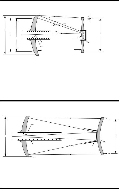
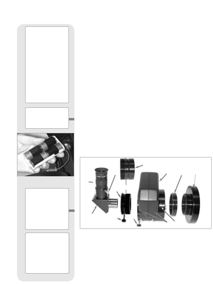
The Meade Schmidt-Cassegrain Optical System
(2) |
(1) |
|
(1) |
|
(2) |
|
Ray (2) |
1/2° |
Ray (1) |
|
|
8.218" |
|
|
(2) |
|
|
8.016" |
|
8.0" |
(1) |
Secondary |
|
8.0" |
|
|
Mirror |
|
|
Focal |
|
|
Plane |
|
Secondary |
Primary Baffle Tube |
|
Baffle |
|
|
|
Field Stops |
Correcting |
|
|
|
|
Primary Mirror |
Plate |
|
|
|
|
|
|
(8" model depicted in diagram. Not to scale.) |
In the Schmidt-Cassegrain design of the Meade 8", 10", 12", 14", and 16" LX200GPS models, light enters from the right, passes through a thin lens with 2-sided aspheric correction (“correcting plate”), proceeds to a spherical primary mirror, and then to a convex secondary mirror. The convex secondary mirror multiplies the effective focal length of the primary mirror and results in a focus at the focal plane, with light passing through a central perforation in the primary mirror.
The Meade 8", 10" and 12" Schmidt-Cassegrain models include an oversize primary mirror, yielding a fully illuminated field- of-view significantly wider than is possible with a standard-size primary mirror. Note that light ray (2) in the figure would be lost entirely, except for the oversize primary. It is this phenomenon which results in Meade Schmidt-Cassegrains having off-axis field illuminations about 10% greater, aperture-for-aperture, than other Schmidt-Cassegrains utilizing standard-size primary mirrors. Field stops machined into the inside-diameter surface of the primary mirror baffle tube significantly increase lunar, planetary, and deep-space image contrast. These field stops effectively block off-axis stray light rays.
The Meade Maksutov-Cassegrain Optical System
The Meade 7" (178mm) Maksutov-Cassegrain Optical System
Field Stops |
|
8.25" |
7" |
Focal |
Meniscus |
Plane |
Lens |
Primary Baffle Tube |
|
|
Secondary Baffle |
Primary Mirror (f/2.5) |
(Diagram not to scale) |
The Meade 7" Maksutov-Cassegrain design optimizes imaging performance by utilizing a combination of a two-sided spherical meniscus lens (right), a strongly aspheric f/2.5 primary mirror, and a spherical secondary mirror. The convex secondary mirror multiplies the effective focal length of the primary by a factor of six, resulting in an overall a focal length of 2670mm and a focal ratio of f/15 system at the Cassegrain focus.
The oversize 8.25" primary mirror results in a fully-illuminated (unvignetted) field of view significantly wider than can be obtained with Maksutov optics incorporating primary mirrors of the same aperture as their meniscus correcting lenses. Computer-optimized primary and secondary mirror baffles, as well as a sequence of field stops internal to the primary mirror baffle, yield lunar, planetary, stellar, and deep-space images of uncommonly high contrast and resolution.

WARNING!
Never use a Meade® LX200GPS Telescope to look at the Sun! Looking at or near the Sun will cause instant and irreversible damage to your eye. Eye damage is often painless, so there is no warning to the observer that damage has occurred until it is too late. Do not point the telescope or its viewfinder at or near the Sun. Do not look through the telescope or its viewfinder as it is moving. Children should always have adult supervision while observing.
Caution: Use care to install batteries in the orientation indicated by illustration in the battery slots of the battery holder. Follow battery manufacturer's precautions. Do not install batteries backwards or mix new and used batteries. Do not mix battery types. If these precautions are not followed, batteries may explode, catch fire, or leak. Improperly installed batteries void your Meade warranty.
If you are anxious to use your telescope for the first time, read the QUICK-START GUIDE on pages 4 and 5.
16" LX200GPS Users: See APPENDIX F, page 62, for features unique to the 16" model.
14" LX200GPS Users: See APPENDIX G, page 66, for features unique to the 14" model.
® The name "Meade" and the Meade logo are trademarks registered with the U.S. Patent Office and in principal countries throughout the world. "LX200GPS" and "Autostar II" are trademarks of Meade Instruments Corporation.
"Easy Align" U.S. patent 6,392,799 and other patents pending.
Intelligent Network Architecture to Facilitate Parallel Task Management U.S. patent 6,304,376
© 2003 Meade Instruments Corporation.
CONTENTS |
|
Quick-Start Guide .......................................................... |
4 |
Telescope Features ...................................................... |
6 |
Autostar II Features........................................................ |
9 |
Getting Started .............................................................. |
12 |
Parts Listing .............................................................. |
12 |
How to Attach the Tripod to the Telescope .............. |
12 |
How to Assemble Your Telescope ............................ |
13 |
Choosing an Eyepiece .............................................. |
14 |
Mounting and Adjusting the Viewfinder .................... |
15 |
Observing ...................................................................... |
16 |
Observing by Moving the Telescope Manually ........ |
16 |
Terrestrial Observing ................................................ |
16 |
Observing Using Autostar II's Arrow Keys ................ |
16 |
Focusing the Eyepiece with the Microfocuser .......... |
17 |
Slew Speeds ............................................................ |
17 |
Observe the Moon, Astronomical Observing .......... |
18 |
To Track an Object Automatically.............................. |
18 |
Moving Through Autostar II’s Menus .................. |
18 |
Automatic Alignment ............................................ |
18 |
Observe a Star Using Automatic Tracking .......... |
20 |
Go To Saturn ............................................................ |
20 |
Using the Guided Tour .............................................. |
20 |
Basic Autostar II Operation ............................................ |
22 |
Autostar II Navigation Exercise ................................ |
22 |
Navigating Autostar II................................................ |
23 |
Autostar II Menus ........................................................ |
24 |
Menu Tree ................................................................ |
24 |
Objects Menu............................................................ |
25 |
Event Menu .............................................................. |
26 |
Glossary Menu, Utilities Menu .................................. |
27 |
Setup Menu .............................................................. |
28 |
Hot Button Menus .................................................... |
31 |
Advanced Autostar II Features ...................................... |
32 |
Adding Observing Sites ............................................ |
32 |
Creating User Objects .............................................. |
33 |
Observing Satellites, Landmarks .............................. |
34 |
Identify ...................................................................... |
35 |
Browse ...................................................................... |
36 |
Alternate Alt/Az Alignment Methods.......................... |
37 |
Initialize Autostar II (for Alternate Alignments) .......... |
37 |
Easy (Two-Star) Alignment ...................................... |
37 |
Two-Star Alt/Az Alignment ........................................ |
37 |
To Set the Home Position Manually .................... |
38 |
One-Star Alt/Az Alignment ........................................ |
38 |
Periodic Error Correction .......................................... |
39 |
Photography .................................................................. |
40 |
Optional Accessories ...................................................... |
41 |
Maintenance .................................................................. |
44 |
Specifications ................................................................ |
47 |
Appendix A: Equatorial (Polar) Alignment ...................... |
50 |
Appendix B: Latitude Chart ............................................ |
55 |
Appendix C: How to Create Your Own Guided Tour ...... |
56 |
Appendix D: Training the Drive ...................................... |
60 |
Appendix E: The Moon Menu ........................................ |
61 |
Appendix F: 16" LX200GPS Features............................ |
62 |
Appendix G: 14" LX200GPS Features .......................... |
66 |
Appendix H: De-rotater and Microfocuser Assembly .... |
67 |
Appendix I: Smart Mount................................................ |
68 |
Basic Astronomy ............................................................ |
70 |
QUICK-START GUIDE
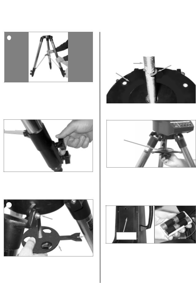
It is recommended that you attach the supplied tripod to the LX200GPS for observing. Perform the telescope and Autostar II setup indoors in the light so that you become familiar with the parts and operation before moving the telescope outside into the dark for observing. The setup is the same for the standard field tripod and the giant field tripod.
1Remove the field tripod from the shipping carton. Stand the tripod vertically with the tripod feet down and with the tripod still fully collapsed. Grasp two of the tripod legs and, with the full weight of the tripod on the third leg, gently pull the legs apart to a fully open position.
2Thread in two lock-knobs on each leg (six total) near the foot of each tripod leg. Use the lockknobs to vary the height of the inner, extendible tripod leg sections. Tighten the locks to a firm feel only; do not overtighten.
Slide rod through Tripod base
Line up with leg
Spreader Bar
3.Remove the threaded rod from the tripod head. A small piece of plastic holds the threaded rod in place. Remove the small plastic bag that is stapled to the threaded rod. This bag contains the "C" clip retainer and an extra clip.
Remove the spreader bar (see above figure) from the shipping carton. Slide the spreader bar onto the threaded rod. Slide the rod through the tripod base. Position the spreader bar so that its three arms line up with the three tripod legs.
|
RodThreaded |
“C” Clip |
|
|
in slot |
Tripod |
|
|
Base |
|
|
|
|
|
4.Place the "C" clip into the slot in the threaded rod above the tripod head—this clip holds the threaded rod in place.
Tension
Knob
5.Take the LX200GPS from its packaging and place the entire telescope onto the top of the tripod head, inserting the threaded rod into the central hole in the bottom of the drive base of the telescope. Tighten the tension knob (see above figure) to a firm feel only; firm tightening of the tension knob is sufficient to result in rigid positioning of the tripod legs.
Battery
Compartment
6.Remove the covers of the battery compartments located on the fork arms (one on each fork arm) and carefully lift the battery holders from their compartments, being mindful of the connector wires. Insert four (user-supplied) C-cell batteries into each battery holder, oriented as shown on the diagram on the battery holder. Return the battery holders to their respective compartments. Replace the covers when you are done.
4
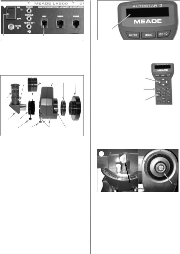
ON/OFF |
HBX Port |
7Press the computer control panel power switch to OFF, if necessary. Remove the Autostar II handbox and the Autostar II coil cord from the packing materials. Plug one end into the HBX port of the telescope's computer control panel and plug the other end into the coil cord port on the Autostar II handbox.

OR
8Attach microfocuser: Remove the dust cap from the rear cell port (A) of the telescope (Note: Telescope not shown for clarity). Thread the microfocuser adapter (
Slide the microfocuser
adapter and tighten the three hex screws on the microfocuser (K) using the provided hex keys.
Important Note:
The Microfocuser is shipped with the microfocuser adapter (B) threaded to the SC accessory adapter (L).
Unthread the adapters from each other before attaching the microfocuser. Set aside the SC accessory adapter. For more information about the SC accessory adapter, see SC OPTIONAL ACCESSORY USERS, page 14.
1.25" Diagonal Prism Users: If using the 1.25" diagonal prism (G), slide the 1.25" adapter (D) into the microfocuser. Line up the thumbscrew into the groove in the microfocuser (I, also see Fig. 7a and 7b, page 14). Slide the 1.25" diagonal prism into the adapter (D). Tighten the adapter thumbscrew (H) to a firm feel only. Tighten the microfocuser thumbscrews (I) to a firm feel only.
2.0" Diagonal Mirror Users: If using the 2.0" diagonal mirror, slide the mirror directly into the microfocuser (C). Tighten the microfocuser thumbscrews (I) to a firm feel only.
Display
9.Press the Power Switch on the computer control panel to the ON position. The copyright message lights on Autostar II's LCD display.
|
|
|
|
Arrow |
|
|
|
|
|
|
|
|
|
|
|
|
|
|
|
|
|
|
|
Slew Speeds: |
|
|
|
|
|
|
Speed 9: Fast |
Keys |
|
|
|
|
|
|
|
|
|
|
|
. |
|
|
|
|
|
|
. |
Speed |
|
|
|
|
|
|
Speed 5: Medium |
|
|
|
|
|
|
Key |
|
|
|
|
|
. |
|
|
||
|
|
. |
|
|
|
|
|
|
|
Speed 1: Slow |
Number |
|
|
|
|
|
|
|
|
|
|
|
|
|
Keys |
|
|
|
|
|
|
|
|
|
|
|
|
|
|
|
|
Press the key prompted by Autostar II to accept the Sun warning. Autostar II now displays "Automatic Alignment." You can then use the Arrow keys to slew (move) the telescope up, down, right, or left. To change the telescope’s slew speed, press the Speed key and then the Number keys. "9" is the fastest speed and "1" is the slowest speed. See page 17 for more details.
R.A. |
|
Dec. |
Lock |
|
Lock |
|
|
|
11.Tighten, to a firm feel only, the R.A. and Dec. locks. Remove the dust cover from the end of the telescope tube.
Place the Super Plössl 26mm eyepiece (F) into the diagonal prism (G) and tighten the attachment thumbscrew (E) to a firm feel only.
Sight along the side of the telescope’s main tube to locate an object. Rotate the mirror lock knob (9, Fig. 1) towards the “Unlock” position, until it feels loose—the telescope is shipped with the mirror locked. Use the telescope’s coarse focus knob (6, Fig. 1) to bring the object into focus. Practice using the Autostar II Arrow keys to center an object in the telescope’s field of view.
5

TELESCOPE FEATURES
2@ |
2! |
2% |
2) |
1( |
|
1* |
|
|
|
(not shown, |
|
|
|
|
|
|
on left fork |
|
|
|
|
|
|
arm) |
|
|
|
2# |
|
|
|
|
|
|
(not |
|
|
|
|
|
|
shown) |
|
|
|
|
|
|
2$ |
|
|
|
|
|
|
B |
|
|
|
|
|
|
c |
|
|
|
|
|
1& |
d |
|
|
|
|
|
|
|
|
|
|
|
|
|
e |
|
|
|
|
|
1^ |
f |
|
|
|
|
|
1% |
|
|
|
|
|
|
|
g |
|
|
|
|
|
1$ |
|
|
|
|
|
|
|
h |
|
|
|
|
|
|
i |
|
|
|
|
|
|
j |
|
|
|
|
|
|
1) |
|
|
|
|
Autostar II |
|
|
|
|
|
Hand Controller. |
||
|
|
|
|
|
||
|
|
|
|
|
See page 9. |
|
1! |
|
|
|
|
|
|
1@ |
|
|
|
|
|
|
|
|
|
|
|
|
|
1# |
|
|
|
|
||
|
|
|
|
|||
Fig. 1: The LX200GPS Telescope; Computer Control Panel (inset); Autostar II Handbox (inset).
6
Caution:
Using products other than standard Meade accessories may cause damage to the telescope’s internal electronics and may void the Meade warranty.
BWant to learn more about the eyepieces available for your LX200GPS telescope?
See OPTIONAL ACCESSORIES, pages
FWant to learn how to attach the microfocuser assembly to the rear cell port of your
LX200GPS telescope?
See HOW TO ASSEMBLE YOUR TELESCOPE, pages 13 and 14.
LX200GPS: YOUR PERSONAL UNIVERSE
versatile, high-resolution telescopes. alignment, zero image-shift microfocusing, automatic tracking of celestial objects, perilibrary of 145,000+ objects in the Autostar II
unmatched state-of-the-art performance.
from 50 yards or study the rings of the planet Saturn from a distance of 800 million miles. Focus beyond the Solar System on
D1.25" Diagonal Prism (or 2" Mirror): Provides a more comfortable right angle viewing position. A 2" diagonal mirror with a 1.25" adapter is standard with the 12" model. See page 14 for information about attaching the prism or mirror to the microfocuser.
EDiagonal Prism Thumbscrew: Tightens the diagonal prism in place. Tighten to a firm feel only.
F Rear Cell Port: The microfocuser assembly threads onto this port.
GCoarse Manual Focus Knob: Moves the telescope’s primary mirror in a finelycontrolled motion to achieve coarse image focus. The LX200GPS telescopes can be focused on objects from a distance of about 25 ft. to infinity. Rotate the focus knob counterclockwise to focus on distant objects, and clockwise to focus on nearby objects.
H Fork Arms: This heavy-duty mount holds the optical tube securely in place.
IBattery Compartments: Insert four user-supplied C-cell batteries into each compartment (one compartment on each fork arm; eight batteries total).
JPrimary Mirror Lock: Rotate this knob towards the "Lock" position and adjust the
tension to a firm feel; this action serves to lock in the coarse focus and also to prevent mirror flop. Use in conjunction with the Zero Image-Shift Microfocuser (see 2$).
1) Right Ascension (R.A.) Slow-Motion Control: Make fine adjustments in the Right Ascension, i.e., the horizontal axis, by turning this control with the R.A. Lock (see below) in the unlocked position. Set the R.A. Lock to a "partially locked" position to create a comfortable drag for the R.A. Slow Motion Control.
Caution: Do not operate the R.A. Slow Motion Control with the R.A. Lock in the fully locked position, as such operation may result in damage to the internal gear system and also cause you to lose alignment.
1! Right Ascension (R.A.) Setting Circle: See APPENDIX A, page 50, for detailed information.
1@ Right Ascension (R.A.) Lock: Controls the manual horizontal rotation of the telescope. Turning the R.A. lock counterclockwise unlocks the telescope, enabling it to be freely rotated by hand about the horizontal axis. Turning the R.A. lock clockwise locks the telescope, prevents the telescope from being rotated manually, and engages the horizontal motor drive for Autostar II operation.
1# Computer Control Panel (see Fig. 1 inset):
A.ON/OFF Switch: Turns the computer control panel and Autostar II ON or OFF. The red power indicator LED next to the switch illuminates when power is supplied to the Autostar II handbox, the microfocuser, and to the telescope’s motor drives (the LED can be turned off in the Panel Light menu; see page 27).
7

Definitions
Throughout this manual, you will notice the terms
"Alt/Az," "Right Ascension," and "Declination." Alt/Az or more properly, altazimuth, is frequently used to refer to altitude or Declination
(the up-and-down vertical movement of the telescope) and azimuth or Right Ascension (the side-to-side horizontal movement of the telescope). Right Ascension is abbreviated as "R.A." and Declination as "Dec."
Important Note:
After the telescope is aligned (see page 18), the Dec. slow motion control 1^ may be used and the telescope will remain in alignment. However, if the R.A. slow motion control 1) is used after the telescope has been aligned, alignment will be lost and the telescope will need to be realigned.
1$
1%
1^
1&
1*
1(
2# 2$
2%
B.12vDC Power Connector: Provides a connection so that the telescope assembly may be powered from a standard 115v AC home outlet using the optional #547 Power Adapter with Cable or the optional 12v DC #607 Cigarette Lighter Adapter. See OPTIONAL ACCESSORIES, page 43.
C.Focus Port: Plug the microfocuser into this port. Control the microfo-
cuser through the Autostar II menus. See HOT BUTTON MENUS, page 31, and 2$ below.
D.Reticle Port: Plug the optional reticle eyepiece into this port. Control the reticle through the Autostar II menus. See HOT BUTTON MENUS page 31. Also see OPTIONAL ACCESSORIES, page 42.
Note: See the instruction sheets that are included with the focuser, the reticle, and the autoguider for more details.
E.12vDC Output: Use the 12vDC output to power telescope accessories and the Maksutov fan on the 7" LX200GPS model..
F.Handbox (HBX) Port: Plug the Autostar II coil cord into this port.
G.RS232 Ports (2): Provides connection with a PC and for current and future Meade accessories. Your PC can control your LX200GPS telescope using serial commands. Go to the Meade website (www.meade.com) to download the latest serial commands and device pinouts.
H.Autoguider Port: Plug the optional autoguider into this port. See the instruction sheet that came with your autoguider for more information.
Tiltable Autostar II Holder: Attach to fork handles (see 1% below). Holds your handbox in a convenient location.
Fork Handles: Use to lift optical tube assembly or to rotate the telescope when attached to the tripod.
Declination (Dec.) Slow-Motion Control: Make fine adjustments in Declination (altitude) by turning this control with the Dec. Lock (see 1& below) in the locked position. In order for this control to operate properly, power must be off.
Dec. Lock: Controls the manual vertical movement of the telescope. Turning the Dec. lock counterclockwise unlocks the telescope enabling it to be freely rotated by hand about the vertical axis. Turning the Dec. lock clockwise (to a firm feel only) prevents the telescope from being moved manually, but engages the vertical motor drive for Autostar II operation.
Dust Cover: Gently pry the dust cover from the front lens of the telescope.
Note: The dust cover should be replaced after each observing session and the power turned off to the telescope. Verify that any dew that might have collected during the observing session has evaporated prior to replacing the dust cover.
Optical Tube: The main optical component that gathers the light from distant objects and brings this light to a focus for examination through the eyepiece.
Circle (on left fork arm): See APPENDIX A, page 50,
: Use these six screws to adjust the alignment
-power, wide-field sighting scope with crosshairs that enables easy centering of objects in the telescope eyepiece.
GPS Receiver (see page 21 for photo): Receives information transmitted from Global Positioning System satellites. See pages 18, 19, and 21 for more information.
4-Speed Zero Image-Shift Microfocuser: Allows precise image focus during visual, CCD, and astrophotographic applications. Maintains precise image centering on even the smallest CCD chips. Operates at four speeds: Fine to fast using the Arrow keys of the Autostar II hand controller. Plug microfocuser into the Focus port (13C, Fig. 1).
Tube Adapters: The optical and mechanical axes of the LX200GPS telescope have been carefully aligned at the factory to ensure accurate object pointing. Do not loosen or remove the optical tube assembly from the tube adapters. The resulting misalignment of the axes will result in inaccurate slewing of the telescope in the GO TO mode.
8
Want to learn more about downloading the latest updates of Autostar II software from the Meade website? See page 31.
AUTOSTAR II FEATURES


Tour the Cosmos with Just the Push of a Button
Control of the LX200GPS telescope models is through the operation of the standard Autostar II system. Nearly all functions of the telescope are accomplished with just a few pushes of Autostar II’s buttons.
system will be Download the list, and soft- (Requires the
.)
objects stored
in the object library, including: |
|
Library |
# of Objects |
New General Catalog (NGC): |
7,840 |
Index Catalog (IC): |
5,386 |
Messier Catalog (M): |
110 |
Caldwell Catalog: |
109 |
Named Objects: |
227 |
Herschel Catalog: |
400 |
Abell Catalog of Galaxy Clusters: |
2,712 |
Arp Catalog of Irregular Galaxies: |
645 |
Uppsala Galaxy Catalog: |
12,940 |
Morphological Catalog of Galaxies: |
12,939 |
General Catalog of Variable Stars: |
28,484 |
SAO: |
17,191 |
Hipparcos Star Catalog: |
17,325 |
■Take a guided tour of the best celestial objects to view on any given night of the year.
■Control your LX200GPS with your PC using an RS232 interface.
■Align your telescope automatically using GPS (Global Positioning System).
■Access a glossary of astronomical terms.
■Mount the telescope in the “Alt/Az” mode (altitude—azimuth, or vertical—hori- zontal) for fully automatic tracking of celestial objects.
9
eWant to learn more about using the GO TO function? See page 20.
Want to learn how to perform a spiral
SPEED
1
changing slew
? See page 17.
FOCUS
4
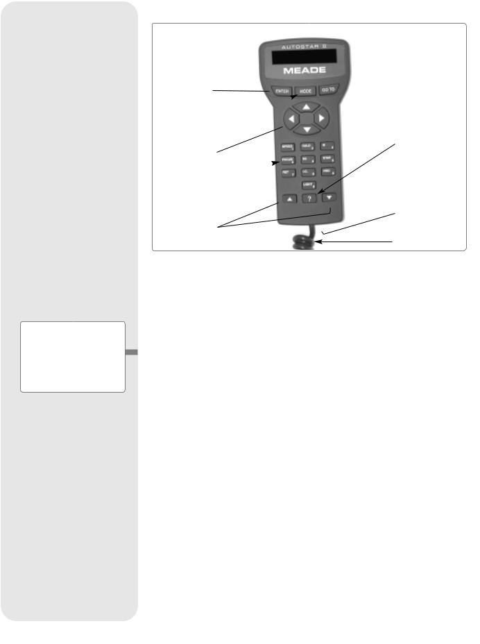
The Autostar II system provides control of virtually every telescope function. The Autostar II handbox has soft-touch keys designed to have a positive feel. The LCD (Liquid Crystal Display) is backlit with red LEDs (Light Emitting Diodes) for easy viewing in the dark. The backlit display, key arrangement, and sequential menu structure make Autostar II extremely user friendly.
B2-Line LCD Display: This screen displays Autostar II's menus and information about the telescope.
•Top line: Lists the primary menu.
•Bottom line: Displays other menus that may be chosen, menu options, telescope status, or information about a function that is being performed.
cENTER Key: Press to go to the next menu level or to choose an option in a menu. The ENTER key is similar to the RETURN or ENTER key on a computer. See MOVING THROUGH AUTOSTAR II'S MENUS, page 18 and AUTOSTAR II MENUS, page 24.
dMODE Key: Press to return to the previous menu or data level. The top menu level is “Select Item." The MODE key is similar to the ESCAPE key on a computer.
Note: Pressing MODE repeatedly while in the “Select Item” level moves Autostar II to the topmost screen: “Select Item: Object.”
Note: If MODE is pressed and held for two seconds or more, information about the telescope's status displays. When the status displays, press the Scroll keys (7, Fig. 2) to display the following information:
•Right Ascension and Declination (astronomical) coordinates
•Altitude (vertical) and Azimuth (horizontal) coordinates
•Local Time and Local Sidereal Time (LST)
•Timer and Alarm Status
•Date
•Site coordinates
•Battery status
coordinates of the curoperation may be Pressing GO TO again or GO TO pro-
an Arrow key to slew at any one of nine different speeds. See SLEW SPEEDS, page 17. Use the Up and Down Arrow keys
to move the telescope vertically up and down. The Left Arrow key rotates the telescope horizontally counterclockwise, while the Right Arrow key rotates it clockwise (unless reversed for Southern Hemisphere use).
Also, use the Arrow keys to scroll through numbers 0 through 9 and the alphabet. The Down Arrow key begins with the letter "A;" the Up Arrow key begins with digit "9."
Additionally, use the Arrow keys to to move the cursor across the display: Use the Right or Left Arrow key (5, Fig. 2) to move the cursor from one number to the next in the display.
gNumber Keys: Press to input digits 0 to 9. Each Number key also has a specific function, which is printed on each key (these are commonly known as "hot but- tons"—see page 31):
1SPEED: Changes the slew speeds. To operate, press Speed and then a Number key (1 is the slowest speed, 9 is highest speed).
2CALD (Caldwell): Press to display the Caldwell catalog on the Autostar II handbox.
3M (Messier): Press to display the Messier catalog library.
4FOCUS: Press to display the Focus Control menu.
10
Tip:
When an astronomical term appears in [brackets], press ENTER for a definition or more detailed information. Press MODE to return to the scrolling
Autostar II Help display.
If a celestial object's name appears in brackets (and your telescope is aligned), press ENTER and then GO TO to slew the telescope to the object.
9 NGC (New General Catalog): Press to display the NGC catalog library.
0 LIGHT: Press to turn on and off the red utility light on the top of the handbox.
hScroll Keys: Press to access options within a selected menu. The menu is displayed on the first line of the screen. Options in the menu are displayed, one at a time, on the second line. Press the Scroll keys to move through the options. Press and hold a Scroll key to move quickly through the options.
The Scroll keys also control the speed of text scrolling on the Autostar II display. When text is scrolling, press and hold the Up Scroll key for a faster display speed and the Down Scroll key for a slower display speed.
i? Key: Press to access the "Help" file. "Help" provides on-screen information on how to accomplish whatever task is currently active.
Press the ? key and then follow the prompts on the display to access details of Autostar II functions in the Help feature. The Help system is essentially an onscreen instruction manual.
If you have a question about an Autostar II operation, e.g., INITIALIZATION, ALIGNMENT, etc., press the ? key and follow the directions that scroll on the second line. When satisfied with the Help provided, press MODE to return to the original screen and continue with the chosen procedure.
jCoil Cord Port: Plug one end of the Autostar II coil cord (10, Fig. 2) into this port located at the bottom of the Autostar II handbox.
1) Coil Cord: Plug one end of the Autostar II coil cord into the HBX port (13F, Fig. 1) of the computer control panel of the telescope and the other end into the Autostar II coil cord port. See j above.
1! Utility Light: Use this built-in red light to illuminate star charts and accessories without disturbing your eye's adaptation to darkness. Press "0" to turn the light on and off.
LX200GPS TIPS
Join an Astronomy Club, Attend a Star Party
One of the best ways to increase your knowledge of astronomy is to join an astronomy club. Check your local newspaper, school, library, or telescope dealer/store to find out if there’s a club in your area.
At club meetings, you will meet other astronomy enthusiasts with whom you will be able to share your discoveries. Clubs are an excellent way to learn more about observing the sky, to find out where the best observing sites are, and to compare notes about telescopes, eyepieces, filters, tripods, and so forth.
Often, club members are excellent astrophotographers. Not only will you be able to see examples of their art, but you may even be able to pick up some “tricks of the trade” to try out with your LX200GPS telescope. See page 40 for more information about photography with the LX200GPS.
Many groups also hold regularly scheduled Star Parties at which you can check out and observe with many different telescopes and other pieces of astronomical equipment. Magazines such as Sky & Telescope and Astronomy print schedules for many popular Star Parties around the United States and Canada.
11
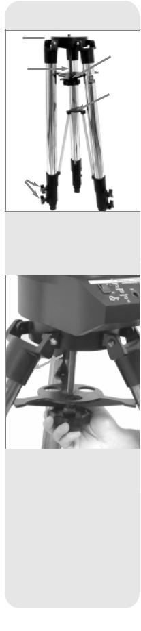


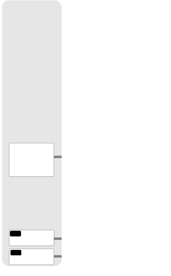
Fig. 3: Tripod components: (1) Tripod
Head; (2) Threaded Rod; (3) Tension Knob; (4) Spreader Bar; (5) Lock Knobs; (6) Strut Hub
Fig. 4: Attaching the telescope to the tripod. Note the orientation of the spreader bar.
12
GETTING STARTED
Parts Listing
Getting the telescope ready for first observations requires only a few minutes. When first opening the packing box, note carefully the following parts:
■LX200GPS Telescope with fork mount system
■Autostar II handbox and interface coil cord; handbox holder
■Microfocuser assembly
■8 x 50mm viewfinder assembly
■Eyepiece holder and 1.25" diagonal prism (7", 8", and 10" models)
■1.25" Adapter and 2" diagonal mirror (12" model only)
■Super Plössl 26mm eyepiece, packed in a plastic storage container
■Variable height tripod and mounting base (12" model only: Giant variable tripod)
■Set of hex keys
How to Attach the Tripod to the Telescope Assembly
The telescope’s fork mount base (also called a drive base) attaches directly to the field tripod. The telescope in this way is mounted in an “altazimuth” (“altitude-azimuth,” or “vertical-horizontal”) format.
The field tripod also can be used in conjunction with the optional equatorial wedge (see EQUATORIAL WEDGE, page 51) for long exposure astrophotography. The equatorial wedge permits alignment of the telescope’s polar axis with the Celestial Pole (or North Star).
1.Remove the field tripod from the shipping carton. Stand the tripod vertically with the tripod feet down and with the tripod still fully collapsed. Grasp two of the tripod legs and, with the full weight of the tripod on the third leg, gently pull the legs apart to a fully open position.
2.Thread in the 6 lock-knobs (2 on each tripod leg) near the foot of each tripod leg (5, Fig. 3). These lock-knobs are used to fix the height of the inner, extendible tripod leg sections.
Note: Tightening to a firm-feel is sufficient; over-tightening may result in stripping of the knob threads or damage to the tripod legs, and results in no additional strength.
3.The spreader bar has been removed for shipment. To install, first remove the threaded rod (2, Fig. 3) from the tripod head (1, Fig. 3); a small piece of plastic holds the threaded rod in place. Remove the small plastic bag that is stapled to the threaded rod. This bag contains the “C” clip retainer and an extra clip.
4.Slide the spreader bar (4, Fig. 3) onto the threaded rod (note the correct orientation as shown in Fig. 4) and position the threaded rod back through the tripod head. Place the clip retainer ( a “C” clip) into the slot in the threaded rod above the tripod head. This clip holds the threaded rod in place.
5.Position the spreader bar so that the 3 arms of the spreader bar line up with the 3 tripod legs.
6.Place the entire telescope onto the top of the tripod head, and insert the threaded rod into the central hole in the bottom of the drive base of the telescope. Tighten the tension knob (Fig. 4); firm tightening of the tension knob is sufficient to result in rigid positioning of the tripod legs.
7.To vary the tripod height, loosen the 6 leg lock-knobs, slide the 3 inner tripod leg sections out to the desired height, and firmly re-tighten (but do not overtighten) the 6 lock-knobs.
To collapse the tripod (after removing the telescope and equatorial wedge, if applicable) for storage, follow these steps:
1.Rotate the spreader bar 60° from its assembled position, so that one spreader bar arm is located between each adjacent pair of tripod legs.
2.At the base of the tripod is a 3-vane extension strut system, with a circular hub at its center (6, Fig. 3). Grasp the tripod head (1, Fig. 3) with one hand and, with the other hand, pull directly “up” on the central hub of the extension strut system. This operation will cause the tripod legs to move inward to a collapsed position.
Caution:
Use care to install batteries as indicated by the battery compartment. Follow battery manufacturer's precautions. Do not install batteries backwards or mix new and used batteries. Do not mix battery types. If these precautions are not followed, batteries may explode, catch fire, or leak.
Improperly installed batteries void your Meade warranty. Always remove the batteries if they are not to be used for a long period of time.
Note:
14" LX200GPS model users, see page 66 for information on battery installation.
Fig
the functri-
.
sections
threaded
batteries or home outlet , page
Fig. 1).
to arms. Move clockwise
to a firm feel to relock the position of the optical tube.
2.Install batteries: Remove the battery compartment covers (8, Fig. 1) and carefully remove the battery holders, being mindful of the connector wires. Insert four user-supplied C-cell batteries into each battery holder, oriented as shown on the diagram on the battery slots inside the battery holder. Return the battery holders to their respective compartments and replace the covers. (See Fig. 5.)
3.Plug in the Autostar II handbox: Be certain that the power switch on the computer control panel (13A, Fig. 1) is in the OFF position. Plug the coil cord of the Autostar II handbox into the HBX port (13F, Fig. 1).
Note: The Autostar II handbox and the microfocuser do not require batteries; the telescope supplies their power.
|
|
|
|

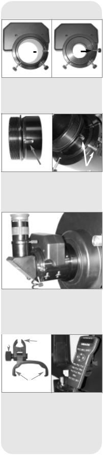
Fig. 6: Microfocuser and eyepiece assembly. (A) Rear cell of telescope (shown separate from the telescope assembly for the sake of clarity, see 5, Fig. 1); (B) Microfocuser adapter; (C) Microfocuser; (D) 1.25" accessory adapter. SC accessory adapter (L) may be used in this position instead if Schmidt-Cassegrain accessories are being used. Do not use either adapter if using a 2" diagonal diagonal mirror; (E) Eyepiece holder thumbscrew; (F)
Eyepiece; (G) 1.25 "Diagonal Prism. 2" diagonal mirror may also be used in this position (12" models); (H) Adapter Thumbscrew; (I) Microfocuser Thumbscrews; (J) Microfocuser bearings; (K) Hex screws; (L) Microfocuser SC Accessory Adapter (see margin note).
4.Attach microfocuser: Remove the dust cap from the rear cell port (5, Fig. 1) of the telescope. Thread the microfocuser adapter (B, Fig. 6) onto the rear cell port thread. Slide the microfocuser (C, Fig. 6) over the microfocuser adapter and tighten the three hex screws (K, Fig. 6) using the provided hex key.
13
Groove
Fig. 7a: Microfocuser groove.
Fig. 7b: Microfocuser adapter thumbscrew in groove.
Groove |
Line up |
|
Fig. 8a: SC adapter groove.
Fig. 8b: Line up SC adapter groove with microfocuser thumbscrew.
Fig. 9: Microfocuser and 1.25 diagonal prism with eyepiece completely assembled.
|
|
|
|
Fig. 10a: Handbox holder: (A) Lock knob; (B) Clamp; (C) Holder.
Fig. 10b: Handbox holder attached to fork arm handle.
5.Attach Diagonal (or accessories)
1.25" Diagonal Prism Users: If using the 1.25" diagonal prism (G, Fig. 6), slide the 1.25" adapter (D, Fig. 6) into the microfocuser. Line up the thumbscrew into the groove in the microfocuser (Fig. 7a and 7b). Tighten the microfocuser thumbscrews (I, Fig. 6) to a firm feel only. Slide the 1.25" diagonal prism into the adapter (D, Fig. 6). Tighten the accessory adapter thumbscrew (H, Fig. 6) to a firm feel only.
SC Optional Accessory Users: If using any of the optional accessories (such as the Off-Axis Guider, T-Adapter, etc.; see page 42) with the LX200GPS SC models, slide the supplied SC accessory adapter (L, Fig. 6) into the microfocuser. Line up the groove on the side of the adapter with either of the microfocuser thumbscrews (Fig. 8a and 8b) and tighten that thumbscrew to a firm feel only. Slide the optional accessory into the accessory adapter. Tighten the other microfocuser thumbscrew to a firm feel only.
2.0" Diagonal Mirror Users: If using the 2.0" diagonal mirror, slide the mirror directly into the microfocuser. The adapters (H and L, Fig. 6) are not required. Tighten the thumbscrews (I, Fig. 6) to a firm feel only.
Plug in the microfocuser: Plug the microfocuser into the Focus port (13C, Fig. 1).
Note: If you wish to mount a camera directly to the microfocuser, you need to attach an optional T-Adapter to the microfocuser. See OPTIONAL ACCESSORIES, page 42.
Important Note: The microfocuser is carefully adjusted at the factory. If it become necessary to adjust the microfocuser, it must be performed by factory trained technicians. If the microfocuser is improperly adjusted, performance will degrade and damage will result. Damage due to improper adjustments not authorized by the factory will not be covered under warranty.
6.Insert eyepiece: Remove the Super Plössl 26mm eyepiece (1, Fig. 1) from its container and place it in the diagonal prism (G, Fig. 6) or diagonal mirror. Tighten the eyepiece holder thumbscrew (2, Fig. 1) to a firm feel only. Rotate the mirror lock knob (9, Fig. 1) towards the “Unlock” position, until it feels loose—the telescope is shipped with the mirror locked.
7.Remove dust cover: Remove the dust cover (18, Fig. 1) from the optical tube assembly (19, Fig. 1) by gently prying it off.
8.Attach the handbox holder: Remove the handbox holder from the plastic bag. If necessary, loosen the lock knob (A, Fig. 10a) and place the clamp (B, Fig. 10a) about one of the fork arm handles (15, Fig. 1). Tighten the lock knob to a firm feel. Slide the Autostar II handbox into the holder (C, Fig. 10a). You may also snap the handbox into the holder: Slide one side of the handbox into the holder and then firmly press the other side of the handbox into the holder until it snaps in place. Adjust the tilt of of the holder by loosening the lock knob and then moving the holder clamp to the desired angle. Retighten the lock knob.
Choosing an Eyepiece
A telescope’s eyepiece magnifies the image formed by the telescope’s main optics. Each eyepiece has a focal length, expressed in millimeters, or “mm.” The smaller the focal length, the higher the magnification. For example: An eyepiece with a focal length of 9mm has a higher magnification than an eyepiece with a focal length of 26mm.
Your telescope comes supplied with a Super Plössl 26mm eyepiece which gives a wide, comfortable field of view with high image resolution.
Low power eyepieces offer a wide field of view, bright, high-contrast images, and eye relief during long observing sessions. To find an object with a telescope, always start with a lower power eyepiece such as the Super Plössl 26mm. When the object is located and centered in the eyepiece, you may wish to switch to a higher power eyepiece to enlarge the image as much as practical for prevailing seeing conditions. For information about optional eyepieces for the your telescope, see OPTIONAL ACCESSORIES, page 41.
14
Mounting
Slot
Track
Thumbscrews
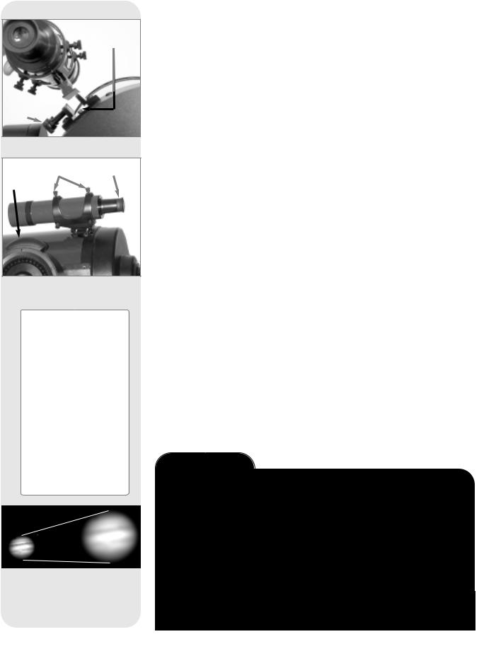
Fig. 11: Viewfinder Assembly.
Collimation |
Viewfinder |
Screws |
Eyepiece |
GPS
Receiver
Fig. 12: Viewfinder collimation screws and eyepiece.
Tip:
Because the space between the GPS receiver and the viewfinder is a bit tight, it is helpful if you tighten the front, bottom viewfinder collimation thumbscrew first and use the other screws to set the alignment. However, if you determine you need to adjust the front thumbscrew, choose an alignment object that allows you to slightly elevate or rotate the telescope to a convenient position for adjustment of this thumbscrew.
Fig. 13a & 13b: Jupiter; examples of the right amount of magnification and too much magnification.
The power, or magnification of a telescope is determined by the focal length of the telescope and the focal length of the eyepiece being used (an eyepiece's focal length is printed on the side of the eyepiece). To calculate eyepiece power, divide the telescope's focal length by the eyepiece's focal lengthFor. example: A 26mm eyepiece is supplied with LX200GPS models. The focal length of the 8" f/10 LX200GPS is 2000mm (see SPECIFICATIONS, pages 47 through 49).
Eyepiece Power = Telescope focal length ÷ Eyepiece focal length Eyepiece Power = 2000mm ÷ 26mm
Eyepiece Power = 77
The eyepiece power, or magnification is therefore 77X (approximately).
Note: For a list of magnification ratings of the eyepieces available for the LX200GPS telescopes, see OPTIONAL ACCESSORIES, page 41.
Mounting and Adjusting the Viewfinder
To align the viewfinder, perform steps 1 through 5 during the daytime; perform step 6 at night.
1.Slide the track on the bottom of the viewfinder into the slot in the viewfinder mounting assembly. See Fig. 11. To secure the viewfinder to the mounting assembly, tighten the two thumbscrews (Fig. 11) to a firm feel only.
2.If you have not already done so, insert the Super Plössl 26mm eyepiece into the diagonal prism.
3.Unlock the R.A. (12, Fig. 1) and Dec. (17, Fig. 1) locks so that the telescope moves freely on both axes.
4.Point the telescope at some well-defined and stationary land object at least 200 yards distant, such as the top of a telephone pole or street sign. Center the object in the telescope eyepiece. Re-tighten the R.A. and Dec. locks.
5.Look through the viewfinder eyepiece (Fig. 12) and loosen or tighten, as appropriate, one or more of the viewfinder collimation screws (Fig. 12) until the
are precisely centered on the object you previously ceneyepiece.
on a celestial object, such as the Moon or a bright star, and refinements, using the method outlined in steps 3 through 5.
conditions vary widely from night-to-night and site-to-site. air, even on an apparently clear night, can distort
image appears fuzzy and ill-defined, back off to a lower for a more well-resolved image (see Fig. 13a and 13b).
Too Much Power?
have too much power? If the type of power you’re referring to is eyepiece magnification, yes, you can! The most common mistake of the beginning observer is to “overpower” a telescope by using high magnifications which the telescope’s aperture and atmospheric conditions cannot reasonably support. Keep in mind that a smaller, but bright and well-resolved image is far superior to one that is larger, but dim and poorly resolved (see Figs. 13a and 13b). Powers above 400X should be employed only under the steadiest atmospheric conditions.
Autostar II can calculate the best eyepiece for you to use. Try out the “Eyepiece Calc” feature in the Utilities menu.
Most observers should have three or four additional eyepieces to achieve the full range of reasonable magnifications possible with the LX200GPS telescopes. See
OPTIONAL ACCESSORIES, page 41.
15
Important Note:
Objects appear upsidedown and reversed left-for- right when observed in the viewfinder. Objects viewed through the telescope eyepiece when inserted into the diagonal prism and microfocuser assembly appear right-side-up, but reversed left-for-right.
This image inversion is of no consequence when observing astronomical objects and, in fact, all astronomical telescopes yield inverted images.
During terrestrial observing, where a fully-correctly-ori- ented image (right-side-up and correct left-for-right) is desirable, an optional #928 45° Erecting Prism is available. See OPTIONAL ACCESSORIES, page 42.
Note:
Viewing conditions vary widely from night-to-night and site- to-site. Turbulence in the air, even on an apparently clear night, can distort images. Low-power eyepieces, such as the Super Plössl 26mm supplied with your telescope, are better suited to resolving images in poor viewing conditions.
OBSERVING
bird, you can
.
. 1).
trees, and other
telescope eye- re-tighten the
loosen the R.A. control knobs
. Before 1) towards
17.
to view some-
but note is caused by handbox operathe Autostar
II Setup menu (see TO TRACK AN OBJECT AUTOMATICALLY, page 18), or by using Autostar II's GO TO capabilities (seeGO TO SATURN, page 20).
Terrestrial Observing
The LX200GPS models are excellent high-resolution terrestrial (land) telescopes. Viewing terrestrial objects requires looking along the Earth's surface through heat waves. These heat waves often cause degradation of image quality. Lower power eyepieces, like the Super Plössl 26mm, magnify these heat waves less than higher power eyepieces. Therefore, lower power eyepieces provide a steadier, higher quality image. If the image is fuzzy or ill-defined, reduce to a lower power eyepiece, where the heat waves do not have such an effect on image quality. Observing in early morning hours, before the ground has built up internal heat, produces better viewing conditions than during late afternoon hours.
Observing Using Autostar II's Arrow Keys
You may observe land and astronomical objects using Autostar II's Arrow keys to move the telescope.
1.Tighten the R.A. and Dec. locks (12 and 17, Fig. 1).
2.Verify that Autostar II is properly connected to your telescope. See HOW TO ASSEMBLE YOUR TELESCOPE, page 13.
3.Flip the telescope power switch to the ON position.
The Autostar II screen is activated and a copyright message displays briefly, followed by a short beep. Then Autostar II takes a few moments to start up the system.
4.A message displays that warns not to look at the Sun. At the end of this message, press the key prompted by Autostar II to signify that the message has been read and understood.
5."Automatic Alignment" displays. Press any Autostar II key to abort automatic alignment.
6.The Arrow keys are now activated. Press the Arrow keys (5, Fig. 2) to slew (move) the telescope up, down, right, or left.
7.Press the Speed key (Number key "1") and then a Number key (6, Fig. 2) to change the telescope’s slew speed. ("1" is the slowest speed, "9" is highest speed.)
8.Use the viewfinder (22, Fig. 1) to locate an object and practice using the Autostar II’s Arrow keys to center the object in the telescope’s field of view.
16

See MIRROR MIRROR, page 38, for more information about the microfocuser and the primary mirror lock.
9.Bring the object into focus (see below).
Focusing the Eyepiece Using the Microfocuser
The LX200GPS zero image-shift microfocuser (24, Fig. 1) allows you to obtain the most precise image focus possible during visual, photographic, and CCD applications, maintaining precise and "jiggle-free" image centering on even the smallest CCD chips.
To use the microfocuser:
1.Perform this part of the procedure during the daytime, without the eyepiece assembly (eyepiece, diagonal, etc.) attached to the microfocuser. Press the Autostar II Focus button and then the Up and Down Arrow keys. Observe the microfocuser drawtube as it travels in and out. When the drawtube reaches the furthest extension of its travel, listen for a change in the pitch of the motor. Notice that the drawtube's maximum extension is about a half-inch out from the microfocuser. Set the drawtube so that it extends about a quarter-inch (about halfway).
2.When you begin your viewing session, attach the eyepiece assembly. See pages 13 and 14 for details.
3.Make sure that the microfocuser is plugged into the computer control panel focus port (13C, Fig. 1).
4.Point the telescope at a bright star.
5.Rotate the mirror lock knob (9, Fig. 1) towards the "unlock" position, until it feels loose. Use the coarse focus control (6, Fig. 1) to achieve a rough focus of the star.
6.Rotate the mirror lock knob towards the "lock" position and adjust the tension to a firm feel; this action serves to lock in the coarse focus.
Important Note: Do not use or bump the coarse focus knob once you have set the coarse focus. If you do so, repeat steps 5 and 6 above to reset the coarse focus.
7.Press the Focus key (Number key "4"). "Focus Control: Speed: Fast" displays. Press the Up or Down Scroll keys to cycle through the four speed options. Press ENTER to select the desired speed. Or press one of the following Number keys after pressing the Focus key to change the speed:
Key # |
Speed |
Key # |
Speed |
1 or 2 |
Fine |
6 or 7 |
Medium |
3, 4, or 5 |
Slow |
8 or 9 |
Fastest |
8.Use the Arrow keys to bring the star into fine focus.
9.You may need to repeat this procedure when you change eyepieces.
Slew Speeds
directly profunctions. change the
at left)
view of a
higher power eyepiece, such as a 12mm or a 9mm eyepiece.
Speeds 4, 5, or 6: Enable centering of an object in the field of a low-to-moderate power eyepiece, such as the standard Super Plössl 26mm.
Speeds 7 or 8: Best used for rough centering of an object in the viewfinder.
Speed 9: Moves the telescope quickly from one point in the sky to another.
17

Definition: Initialization is a procedure that ensures that Autostar II operates correctly. When you first use
Autostar II, it doesn't yet know where the observation location site is or the time or date of the observation session.
During the automatic alignment procedure, the system calculates these parameters automatically.
Autostar II uses this information to precisely calculate the location of celestial objects (such as stars and planets) and to move your telescope correctly for various operations.
Tip:
When multiple choices are available within an Autostar II menu option, the current option is usually displayed first and highlighted by a right pointing arrow (>).
Note:
Press any key on the Autostar II handbox to abort the GPS fix. If aborted, Autostar II then displays "Enter Date." You may follow prompts to perform a manual alt/az alignment (see page 37) or press MODE repeatedly until "Select Item" displays to use the Autostar II menu options.
Observe the Moon
Point your telescope at the Moon (note that the Moon is not visible every night) and practice using the Arrow keys, the microfocuser and the slew speeds to view different features. The Moon contains many interesting features, including craters, mountain ranges, and fault lines. The best time to view the Moon is during its crescent or half phase. Sunlight strikes the Moon at an angle during these periods and adds a depth to the view. No shadows are seen during a full Moon, making the overly bright surface to appear flat and rather uninteresting. Consider the use of a neutral density Moon fil-
. See page 42. Not only does it cut down the Moon's enhances contrast, providing a more dramatic image.
instrument, your telescope has many optical and electroin astronomical applications where the high level of optivisible. The range of observable astronomical objects is
motivation.
Automatically
the night sky, the stars appear to move from East to the stars move is called the sidereal rate. You can setup the sidereal rate so that it automatically tracks (follows) the the night sky. If the telescope is not tracking an astronomiout of the eyepiece field of view. The tracking function
centered in the telescope’s eyepiece.
you need to learn how the Autostar II keypad operates menus. You'll need to initialize and align your telescope.
Autostar II’s Menus
The Autostar II database is organized in levels for quick and easy navigation.
■Press ENTER (2, Fig. 2) to go deeper into Autostar II's menu levels.
■Press MODE (3, Fig. 2) to move back toward the top menu level.
■Press the Scroll keys (7, Fig. 2) to move up and down through the options available for each level.
■Press the Arrow keys (5, Fig. 2) to enter characters and digits. The Arrow keys are also used to move the telescope.
■Use the Number keys to enter digits.
Automatic Alignment Feature
Autostar II offers four methods of altazimuth (alt/az) alignment; this section describes how to initialize and align your telescope using Automatic Alignment. (For a description of the other alt/az alignment methods, see pages 37 and 38. For information about equatorial (polar) alignment, see APPENDIX A, page 50.)
To prepare your telescope for Automatic Alignment:
1.Tighten the R.A. and Dec. locks (12 and 17, Fig. 1).
2.Verify that Autostar II is properly connected to your telescope. See HOW TO ASSEMBLE YOUR TELESCOPE, page 13.
3.Flip the telescope power switch to the ON position.
The Autostar II screen is activated and a copyright message displays briefly, followed by a short beep. Then Autostar II takes a few moments to start up the system.
4.Autostar II initializes the Smart Drive if "On" has been previously chosen from both the R.A. and Dec. PEC menus in the "Setup: Telescope" menu (the very first time the system is turned on, the Smart Drive feature will not be enabled). Once "On" is chosen, Autostar remembers the setting until "Off" is chosen again. If "On" has been selected, the R.A. and Dec. motors operate briefly and "Initializing: Smart Drive" displays.
18

Important Note:
Once the telescope is aligned, only use the Arrow keys to move the telescope. Once the telescope has been aligned, do not loosen the telescope locks (12 and 17, Fig. 1), or move the base manually, or alignment will be lost.
Important Notes:
It is recommended that you do not attempt a GPS fix indoors.
It is also recommended that you CALIBRATE SENSORS the first time your telescope takes a GPS fix.
See page 29 for more information.
5.A message displays that warns not to look at the Sun. At the end of this message, press the key prompted by Autostar II to signify that the message has been read and understood.
6."Automatic Alignment" displays. Press ENTER. The system now performs the following routines (press any Autostar II key to abort Automatic Alignment; see Important Note, at the bottom of page 18) :
Caution: As the telescope performs the following operations, it will swing and rotate. Keep a safe distance from the telescope.
a.Finds the home position. Moves the telescope to find the "home" position. When the home position is found, the system knows the limiting positions of the telescope and can avoid tangling cables and over-rotating the telescope.
b.Detects “level” of the base of the telescope; finds tilt and tip. To detect level, Autostar II must calculate "level" at three compass points. See FINDING TRUE LEVEL in the LX200GPS INFO box on page 21.
Autostar II also determines the positioning (i.e., tilt and tip) of the optical tube.
c.Finds North. Locates magnetic North, then calculates true North. See
FINDING TRUE NORTH, page 21.
d.Attempts a "GPS Fix." The LX200's GPS receiver attempts to acquire and sync up with signals from GPS satellites. "Getting GPS Fix" displays. See THE GLOBAL POSITIONING SYSTEM in the LX200GPS INFO box on page 21.
After performing these operations, Autostar II now knows:
■The telescope's limiting positions
■Where level is for the telescope
■The location of true North
■The observing site's location
■The date and time
e.Star Alignment. Autostar II then chooses two stars to align upon. "Searching...." displays. When the telescope slews (moves) to the first star for
not, the telestar easily telestar.
ALIGN-
LX200GPS TIPS
Which One’s the Alignment Star?
If Autostar has chosen an alignment star with which you are unfamiliar, how can you be sure if the star in your eyepiece is really the alignment star?
The rule of thumb is that an alignment star is usually the brightest star in that area of the sky. If you perform a GO TO to an alignment star and you're not sure if you have located the alignment star or it isn't in the eyepiece, look through your viewfinder. When you view an alignment star in the viewfinder, it stands out dramatically from the rest of the stars in that portion of the sky. The viewfinder will help you locate a star more quickly than the eyepiece, because it has a much wider field of view than the eyepiece. Using Autostar, set the slew speed to 6 or higher and use the Arrow keys to center the alignment star in the viewfinder. If your viewfinder has been aligned with the telescope, the alignment star should now be in the eyepiece. Set the slew speed to 4 or less and center the star in the eyepiece. Also see the "Spiral Search" tip, page 20.
19

Tip:
The GO TO key also allows you to perform a "spiral search." A spiral search is useful when the telescope slews to an object, but that object is not visible in the eyepiece after the telescope finishes its search. (This sometimes occurs during an alignment procedure.)
Press GO TO when the telescope stops slewing. The telescope begins to move in a spiral pattern at a very slow speed around the search area. Look through the eyepiece and when the object does become visible, press MODE to stop the spiral search. Then use the Arrow keys to center the object.
When the procedure is performed correctly, "Alignment Successful" displays. If Autostar II does not display this message, perform this procedure again.
Note: Alignment stars may change from night to night. All that is required is for the observer to center the selected stars in the eyepiece when prompted.
Observe a Star using the Automatic Tracking Feature
Now that your telescope has been aligned, you are able to track celestial objects. In this example, the Autostar II Arrow keys are used to find a star, and then Autostar II's tracking capability automatically keeps the star centered in your telescope's eyepiece.
1.When Automatic Alignment is completed (as described in the previous section), "Select: Object" displays on Autostar II.
2.Select a bright star from one of the Object menus. You may choose any unobstructed, bright star for the purposes of this example. Use the viewfinder (22, Fig. 1) to help line up on the star. Use Autostar II's Arrow keys to center the star in the eyepiece. The tracking motors will then keep the star you have chosen in the center of the eyepiece.
Go To Saturn
This exercise demonstrates how to select a celestial object, the planet Saturn, for viewing from Autostar II’s Solar System library. Objects in the eyepiece should maintain their position even though the Earth is rotating beneath the stars. In other words, the telescope tracks the chosen objects.
Note: Saturn is not visible the entire year; you may need to choose anothAutostar II's many object libraries; however, the probelow, remains the same.
aligned, press Number key "5."
displays. Keep pressing the Scroll Down key until “Solar
.
displays. Then “Saturn” and a set of coordinates dis- (and other planets’) coordinates change throughout the
Slewing...” displays and the telescope slews until it finds to use the Arrow keys to center Saturn precisely in the
eyepiece. Autostar II then automatically moves the telescope so that it "tracks" Saturn (or whatever other object you may have chosen); i.e., Saturn remains centered in the eyepiece.
Using the Guided Tour
The Guided Tour feature is an easy and fun method of exploring Autostar II's GO TO capabilities. This example demonstrates using “Tonight’s Best” Guided Tour.
1.After observing Saturn, keep pressing MODE until “Select Item: Object” displays again.
2.Press the Scroll Down key twice. “Select Item: Guided Tour” displays.
3.Press ENTER. “Guided Tour: Tonight’s Best” displays. Press ENTER.
Note: If you wish to try out other Guided Tours, press the Scroll Down key to scroll through other tour choices. When the tour you wish to select displays, press ENTER.
4.“Tonight’s Best: Searching...” displays. After calculating, “Tonight’s Best: Jupiter” displays.
Note: Different objects may be displayed on a tour list on any given night.
Press ENTER to display information about the object. Press GO TO to move the telescope to the object.
20
5.Press MODE to return to the Tour list. Press the Scroll keys to scroll through the list. Press ENTER when you find the next object you wish to observe.
6.Press and hold down MODE for two seconds to leave the Guided Tour menu.
Other Guided Tours are available, such as "How Far is Far" and "A Star's Life." If you have programming skills, you may wish to create a custom Guided Tour. See CREATE YOUR OWN GUIDED TOUR, page 56.
GPS
Receiver
Fig. 14: LX200GPS GPS Receiver.
LX200GPS INFO
The Global Positioning System
The Global Positioning System (GPS) is comprised of 24 satellites orbiting the Earth that are constantly transmitting their precise position and time. The system provides highly accurate, worldwide positioning and navigation information for any number of applications.
GPS receivers on the Earth acquire signals from three to twelve satellites to determine the precise latitude, longitude, and time of the receiver. (Accuracy of the receiver's position may be within 10 to 15 feet.) As Autostar II uses latitude, longitude, and time information to calculate the positions of celestial objects, GPS is an ideal tool for aligning your LX200GPS telescope.
Detecting True Level
To detect level of the base of the telescope, Autostar II must calculate the tip and tilt of the telescope at three compass points and then compensate for it. Finding level involves the geometric calculations of a "plane." In order to define a plane, three positions are necessary. This is not unlike building a table: For a table to stand level and solid, it must have a minimum of three legs. Autostar II makes gravitational measurements to make a precise determination of true level.
Finding True North
Locating True North is one of the most important ingredients in the alignment of a telescope. True North is the axis—the pole—which the Earth spins about and is a key reference for the motion of the Earth.
As you look at the night sky, the stars seem to move; in fact, if you watched long enough or took a long time-exposure photograph, you'd realize that the stars seem to revolve around one point—the pole or True North. When Autostar II knows where True North is and also knows the time, it can calculate the location of all the other objects in the sky.
One traditional way to find True North is to locate the North Star, Polaris, which lies very close to True North. Another way to calculate True North is to use gyroscopes or accelerometers.
The LX200GPS determines True North by using a magnetic North sensor. The sensor locates magnetic North. Magnetic North is not True North, but a measurement of the magnetic lines of the Earth. Magnetic North may deviate several degrees from True North. But Autostar II, using the observation site location determined by the GPS and magnetic North information, can calculate the position of True North.
Some areas are subject to magnetic disturbances, and the magnetic field of the Earth changes slightly from year to year. Autostar II allows you to adjust for discrepancies in the local magnetic field using the "Calibrate Sensors" option in the Telescope menu. See page 29 for more information.
21
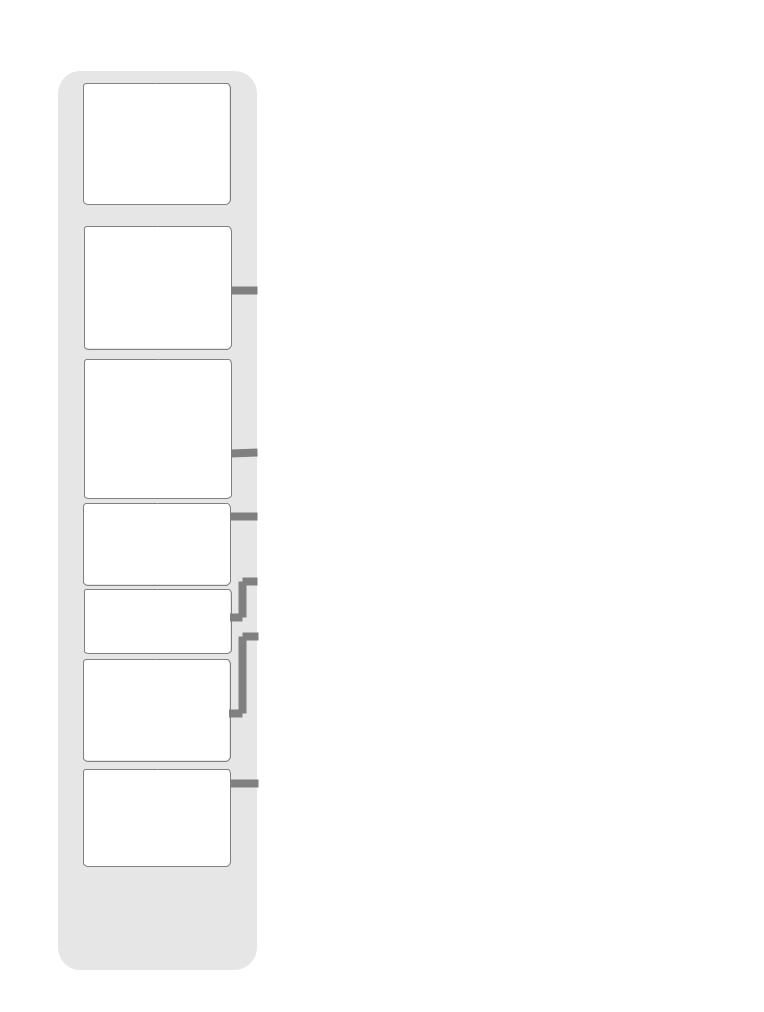
Object
Event
Guided Tours
Glossary
Utilities
Setup
Fig. 16: Menus set in a loop.
Setup
Align
Date
Time
Daylight Saving Telescope Targets
etc.
Fig. 17: Menu options display on the second line. Use the Scroll keys to move up or down through the list of options. Press ENTER to select the desired option.
BASIC AUTOSTAR II
SETUP MENU |
Select Item: |
OBJECT MENU |
|
Automatic alignment |
Want to see Mars? The Orion nebula? |
||
Object |
|||
permits all telescope |
The Andromeda galaxy? Select from |
||
|
|||
operations with only |
|
over 145,000 objects and press |
|
minimal setup. |
|
GO TO to move the telescope |
|
|
|
automatically to an object. |
|
Select Item: |
|
Select Item: |
|
Setup |
|
Event |
|
UTILITIES MENU |
|
EVENT MENU |
|
Calculate eyepiece |
The Universe of |
Display the time of |
|
magnifications; |
past, present, and future |
||
Autostar II |
|||
set timer alerts; |
astronomical events, |
||
create your own |
|
such as Moon phases |
|
landmark survey. |
|
or meteor showers. |
|
Select Item: |
|
Select Item: |
|
Utilities |
|
Guided Tour |
|
GLOSSARY |
|
GUIDED TOUR |
|
What is an elliptical galaxy? |
|
Autostar II escorts you |
|
How far away is the Sun? |
|
on a tour of tonight's |
|
Expand your knowledge of |
Select Item: |
best celestial objects |
|
astronomy by displaying terms |
Glossary |
at your viewing location. |
|
and definitions, and other information. |
|
|
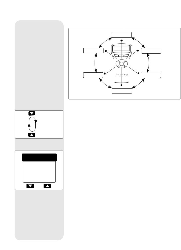
Fig. 15: The Autostar II Universe: The six primary categories listed in the Select Item menu of
Autostar II.
to understand that menu selections are set in a loop (Fig. 16). This means the Scroll Down key (7, Fig. 2) cycles down through all the available within a given category, then returns to the first option. The Scroll Up key (7, up through the options in the opposite order. Note that this capability is a to get to an option that is near the bottom of the list. The following example
this capability.
to the “Select Item: Setup” menu option when the “Select Item: Object” menu is displayed:
1.Press the Scroll Down key five times or the Scroll Up key once.
The screen in Fig. 17 displays two lines of information. The top line shows the current menu level. The second line displays an option which may be selected within that menu level. Some options are choices that select the next menu level down. The Scroll keys move up and down within the list of available options, showing one option at a time.
When the desired option is displayed on the second line, press the ENTER key to choose that option and move down one menu level.
Press the MODE key to leave a level; e.g., the wrong menu option is chosen.
Important Note: No matter how many levels into Autostar II are traveled, each press of the MODE key moves up a level, until the top level, "Select Item," is reached. Once in the Select Item level, press MODE to return to the topmost level, "Select Item: Object."
Autostar II Navigation Exercise
To demonstrate how the Autostar II menu structure works, the following exercise calculates Sunset time so an evening observing session can be planned.
To Calculate Sunset time:
1.Press the MODE key several times, until “Select Item: Object” is displayed.
2.Press the Scroll Down key once to display the “Event” option in the “Select Item” menu.
3.Press the ENTER key to choose the "Event" option and move down a level. "Event: Sunrise" is displayed.
22
 Loading...