


INSTRUCTION MANUAL
10", 12" and 14" Advanced Coma-Free™ f/8 LX600™ with StarLock™
® The name “Meade,” “AutoStar,”“StarLock” and the Meade logo are trademarks registered with the U.S. Patent and Trademark Offi ce and in principal countries throughout the world. Deep Sky Imager,” “LX600,” and “Tonight’s Best” are trademarks of Meade Instruments Corp.
Protected by U.S. Patent: US 6,392,799 and other Patents Pending.
© 2013 Meade Instruments Corp.
 WARNING!
Never use a Meade® LX600 Telescope to look at the Sun!
Looking at or near the Sun will cause instant and irreversible damage to your eye.
Eye damage is often painless, so there is no warning to the observer that damage has occurred until it is too late. Do not point the telescope at or near the Sun. Do not look through the telescope or Finder Scope as it is moving. Children should always have adult supervision while observing.
TRAVEL SCREW
The LX600 f/8 ACF optical tube assembly (OTA) is shipped from the factory with the focusing mechanism protected by a travel screw. This screw secures the primary mirror in a fixed position during travel thereby protecting the focusing mechanism from shock damage. This screw is on the back cell of the OTA, near the focus knob, and is identified by a dab of red paint.
This screw must be removed before attempting to focus the OTA. Failure in removal can result in damage to the focusing mechanism. Retain this screw for future use as it is suggested that mirror be locked down anytime the OTA is shipped.
Move the primary mirror to the travel position by rotating the focus knob counter clockwise until its travel limit is reached. Reattach the travel screw and tighten until firm. Do not over tighten.
Battery Safety Instructions
•Always purchase the correct size and grade of battery most suitable for the intended use.
•Always replace the whole set of batteries at one time, taking care not to mix old and new ones, or batteries of different types.
•Clean the battery contacts and also those of the device prior to battery installation.
•Ensure the batteries are installed correctly with regard to polarity (+ and -).
•Remove batteries from equipment which is not to be used for an extended period of time.
•Remove used batteries promptly.
•Never attempt to recharge primary batteries as this may cause leakage, fire, or explosion.
•Never short-circuit batteries as this may lead to high temperatures, leakage, or explosion.
•Never heat batteries in order to revive them.
•Remember to switch off devices after use.
•Keep batteries out of the reach of children; small batteries may be ingested.
•Seek medical advice immediately if a battery has been swallowed.
CONTENTS
Introduction
The LX600 Telescope . . . . . . . . . . . . . . . . . . . . . . . . . . . 5
Quick Start . . . . . . . . . . . . . . . . . . . . . . . . . . . . . . . . . . . . . . 6
LX600 Features . . . . . . . . . . . . . . . . . . . . . . . . . . . . . . . . . 10
AutoStar II Features . . . . . . . . . . . . . . . . . . . . . . . . . . . . . 14
Getting Started
Parts Listing . . . . . . . . . . . . . . . . . . . . . . . . . . . . . . . . . 17
How To Assemble Your Telescope . . . . . . . . . . . . . . . . . 17
Choosing An Eyepiece. . . . . . . . . . . . . . . . . . . . . . . . . . 19
Observing
Observing Using AutoStar II’s Arrow Keys . . . . . . . . . . . 20 Slew Speeds. . . . . . . . . . . . . . . . . . . . . . . . . . . . . . . . . 20 Astronomical Observing . . . . . . . . . . . . . . . . . . . . . . . . 20 To Track An Object Automatically . . . . . . . . . . . . . . . . . 20 Moving Through AutoStar II’s Menus. . . . . . . . . . . . . . . 21 Automatic Alignment for Alt-Az Mounted Telescopes . . 21 One-star Polar Alignment . . . . . . . . . . . . . . . . . . . . . . . 23 Syncing Your Eyepiece or Camera Using StarLock. . . . . 23 Observe a Star Using the Automatic Feature . . . . . . . . . 24 Calibrate Home . . . . . . . . . . . . . . . . . . . . . . . . . . . . . . . 24 StarLock Operation. . . . . . . . . . . . . . . . . . . . . . . . . . . . 25 Focusers. . . . . . . . . . . . . . . . . . . . . . . . . . . . . . . . . . . . 25 Cameras . . . . . . . . . . . . . . . . . . . . . . . . . . . . . . . . . . . . 25 GoTo Saturn . . . . . . . . . . . . . . . . . . . . . . . . . . . . . . . . . 25 Using the Guided Tour. . . . . . . . . . . . . . . . . . . . . . . . . . 25
AutoStar II Operation
The AutoStar II Handbox . . . . . . . . . . . . . . . . . . . . . . . . 27
AutoStar Navigation Exercise . . . . . . . . . . . . . . . . . . . . 28
Example of Locating a Menu. . . . . . . . . . . . . . . . . . . . . 28
AutoStar II Menu Tree . . . . . . . . . . . . . . . . . . . . . . . . . . 29
Navigating AutoStar II . . . . . . . . . . . . . . . . . . . . . . . . . . 30
Object Menu . . . . . . . . . . . . . . . . . . . . . . . . . . . . . . . . . 30
Event Menu. . . . . . . . . . . . . . . . . . . . . . . . . . . . . . . . . . 31
Glossary Menu . . . . . . . . . . . . . . . . . . . . . . . . . . . . . . . 31
Utilities Menu . . . . . . . . . . . . . . . . . . . . . . . . . . . . . . . . 32
Setup Menu . . . . . . . . . . . . . . . . . . . . . . . . . . . . . . . . . 32
“Hot Button” Menu . . . . . . . . . . . . . . . . . . . . . . . . . . . . 36
StarLock Periodic Error Correction . . . . . . . . . . . . . . . . 36
Advanced Autostar II Features
Adding Observing Sites. . . . . . . . . . . . . . . . . . . . . . . . . 37
Creating User Objects . . . . . . . . . . . . . . . . . . . . . . . . . . 38
Observing Satellites . . . . . . . . . . . . . . . . . . . . . . . . . . . 38
Landmarks . . . . . . . . . . . . . . . . . . . . . . . . . . . . . . . . . . . . . . 39
Identify . . . . . . . . . . . . . . . . . . . . . . . . . . . . . . . . . . . . . 40
Browse . . . . . . . . . . . . . . . . . . . . . . . . . . . . . . . . . . . . . 41
Alternate Alt-Az Alignments . . . . . . . . . . . . . . . . . . . . . 41
Easy Alignment . . . . . . . . . . . . . . . . . . . . . . . . . . . . . . . . . . . 41
Two-Star Alt-Az Alignment . . . . . . . . . . . . . . . . . . . . . . . . . . 42
One-Star Alt-Az Alignment . . . . . . . . . . . . . . . . . . . . . . 42
Polar Drift Alignment (Northern Hemisphere). . . . . . . . . 43
StarLock Automatic Rate Calibration. . . . . . . . . . . . . . . 43
Periodic Error Correction (PEC Training) . . . . . . . . . . . . 43
StarLock Assisted PEC Training . . . . . . . . . . . . . . . . . . 43
Update Menu Option . . . . . . . . . . . . . . . . . . . . . . . . . . . 43
Erase Menu Option . . . . . . . . . . . . . . . . . . . . . . . . . . . . 43
On and Off Menu Option . . . . . . . . . . . . . . . . . . . . . . . . 43
Optional Accessories . . . . . . . . . . . . . . . . . . . . . . . . . . . . . 44
Maintenance . . . . . . . . . . . . . . . . . . . . . . . . . . . . . . . . . . . . 46
Collimation . . . . . . . . . . . . . . . . . . . . . . . . . . . . . . . . . . 46
Inspecting the Optics . . . . . . . . . . . . . . . . . . . . . . . . . . 48
Gauging the Movement of the Telescope. . . . . . . . . . . . 48
Meade Customer Service . . . . . . . . . . . . . . . . . . . . . . . 48
Specifications . . . . . . . . . . . . . . . . . . . . . . . . . . . . . . . . . . . 49
Appendix A
Training the Drive . . . . . . . . . . . . . . . . . . . . . . . . . . . . . 51
Appendix B
StarLock Utility . . . . . . . . . . . . . . . . . . . . . . . . . . . . . . . 52
Appendix C
Automatic Rate Calibration (ARC) . . . . . . . . . . . . . . . . . 54
Appendix D
Split Fork Arms . . . . . . . . . . . . . . . . . . . . . . . . . . . . . . . 55
Appendix E
Equatorial (Polar) Alignment . . . . . . . . . . . . . . . . . . . . . 57
Appendix F
X-Wedge Installation . . . . . . . . . . . . . . . . . . . . . . . . . . . 62
Appendix G
Latitude Chart. . . . . . . . . . . . . . . . . . . . . . . . . . . . . . . . 67
Appendix H
Manual Drift Alignment . . . . . . . . . . . . . . . . . . . . . . . . . 68
Appendix I
The Moon Menu . . . . . . . . . . . . . . . . . . . . . . . . . . . . . . 69
Appendix J
Advanced Coma-Free Optical System . . . . . . . . . . . . . . 70
Recycling . . . . . . . . . . . . . . . . . . . . . . . . . . . . . . . . . . . . . . 71
Meade Warranty
One Year Limited Warranty . . . . . . . . . . . . . . . Back Cover

INTRODUCTION
The LX600 Telescope
Advanced Technology for the Astro Imager and Visual Observer
Congratulations on receiving your new LX600 telescope. You’ll find that this telescope system has all you need to explore the Universe we live in.
Drawing on over 40 years of experience and innovation, Meade Instruments introduces the latest in a long line of advanced astronomical products: the LX600. Using revolutionary new technology, every aspect of this amazing telescope system has been designed to deliver the new standard in astrophotographic and visual performance:
•StarLock™ full-time automatic integrated guider assists with ultra-precise polar alignment, finds and centers targets and then automatically locks onto a field star as faint as 11th magnitude for down to one arcsecond guiding. No separate computer, no guide star selection, no user focus. Just set up your camera and image.
•Fast f/8 Advanced Coma-Free (ACF) optical systems on the 10", 12" and 14" OTAs. These optics produce wider, flatter fields with no coma for pinpoint stars out to the edge of larger imaging sensors or extreme wide angle eyepieces.
•Internal Crayford-style primary mirror focusing system with a dual speed 7:1 focus control, which eliminates image shift and mirror flop. Precise focus is a snap.
•Optional X-Wedge is made from machined aluminum and stainless steel for 30% more stability. Configures the LX600 telescope in the Polar mode which is essential for long exposure astro phototgraphy
If you are like us, you can’t wait to get outside under a dark sky to use your new LX600 telescope. We have provided a Getting Started Guide that will get you up and running in the shortest amount of time possible. After your first experience, please sit down with this manual and read about all the advanced features that are available to you with this telescope system. We are confi dent that the LX600 will keep you fascinated with the Universe and entertained for many years to come.
Clear Skies,
The People at Meade
Introduction
5
Quick Start
6
|
|
H G |
F |
|
|
|
F Leg Lock Knobs |
|
B Tripod Head |
|
|
C Threaded Rod |
G Extension Strut |
|
D T-handle |
H Tension Hub |
|
Tension Knob |
I Retaining clip |
|
E Spreader |
(not visible) |
|
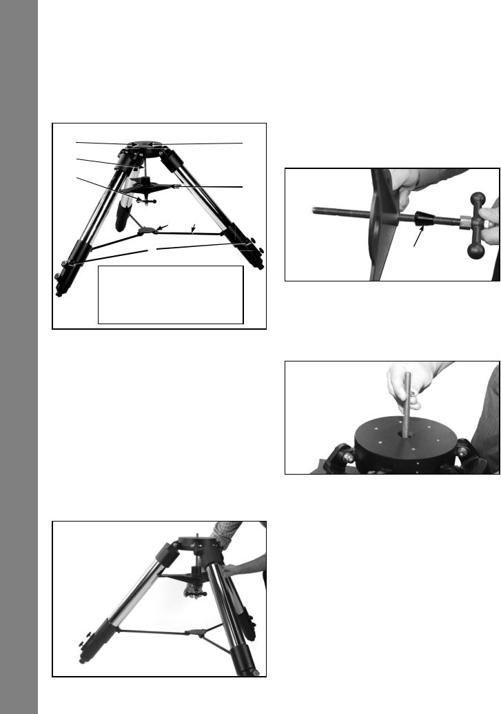
Figure A. Fully assembled tripod.
|
vertically, with the tripod feet down and with the tripod still fully |
|
|
collapsed. Grasp two of the tripod legs and, with the full weight |
|
|
of the tripod on the third leg, gently pull the legs apart to a fully |
|
|
open position (Fig. B). |
|
|
The spreader bar (Fig. A, 4) has been removed for shipment. |
|
|
Slide the spreader bar onto the threaded rod on top of the spacer |
|
I |
that is already on the threaded rod. Position the spreader bar with |
|
the fl at side facing upward (Fig. C). |
||
|
||
E |
|
Spacer
Figure C. Slide the spreader onto the threaded rod.
Slide the threaded rod back through the tripod head from underneath. Push the retaining clip onto the threaded rod in the depressed ring on the threaded rod (Fig. D).
The Field Tripod is supplied as a completely assembled unit, except for the spreader bar (Fig. A, 4). For visual observations and short exposure astro-imaging, the drive base of the telescope’s fork mount is attached directly to the fi eld tripod. The telescope in this way is mounted in an “Altazimuth” (“Altitude-Azimuth” or “vertical-horizontal”) format.
CAUTION: “Firm feel” tightening is sufficient; over-tightening may strip the threads or damage the tripod and results in no additional strength.
B How to Attach the Tripod to the Telescope Assembly. (See Appendix F for attaching the tripod to X-Wedge. ) After removing the Giant Field Tripod from its shipping carton, stand the tripod
Figure B. Extend the tripod legs out.
Figure D. Push the retaining clip onto the threaded rod.
Move the spreader bar so that the three arms of the spreader bar are lined up with the three tripod legs. Place the entire telescope onto the top of the tripod head, and thread the rod into the central threaded hole in the bottom of the drive base of the telescope. Note: that the LX600 features split fork arms; you can now break down the telescope into easier to mount parts (see page 55 for details). Tighten the T-handle tension knob (Fig. A, 3); firm tightening of the tension knob is suffi cient to result in rigid positioning of the tripod legs. It is not necessary to use extreme force in tightening this knob.
To vary the tripod height, loosen the six leg lock knobs and slide the three inner tripod leg sections out to the desired height. Retighten the lock knobs to a firm feel (Fig. E).
Lock knobs
Figure E. Loosen the leg lock knobs, extend the lower portion of the leg and tighten the knobs (turn to a fi rm fi t).
To collapse the tripod (after removing the telescope), rotate the spreader bar 60° from its assembled position, so that one spreader bar arm is located between each adjacent pair of tripod legs. At the base of the tripod is a three-vane extension strut system, with a circular hub at its center (Fig. A, 7). Grasp the tripod head (Fig. A, 1) with one hand and, with the other hand, pull directly “up” on the central hub of the extension strut system. This operation will cause the tripod legs to move inward to a collapsed position.
CAUTION: If the tripod does not seem to extend or collapse easily, do not force the tripod legs in or out. By following the instructions above, the tripod will function properly, but if you are unclear on the proper procedure, forcing the tripod into an incorrect position may damage the extension strut system.
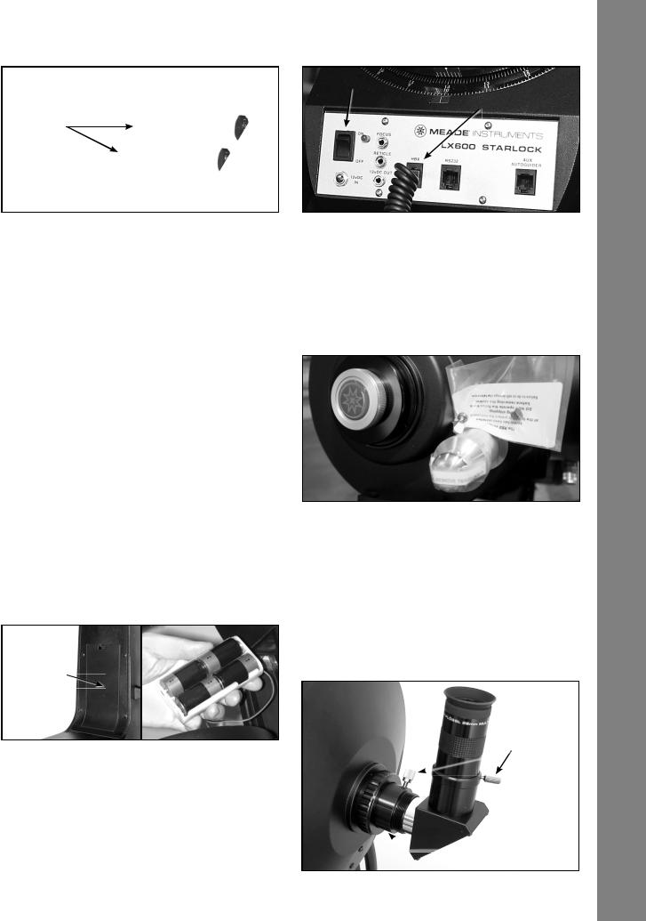
C Remove the covers of the battery compartments located on the fork arms (one on each fork arm) and carefully lift the battery holders from their compartments, being mindful of the connector wires. Insert four (user-supplied) C-cell batteries into each battery holder, oriented as shown on the diagram on the battery holder. Return the battery holders to their respective compartments. Replace the covers when you are done.
Battery compartment
Figure F. The battery compartments are located on inside of each of the fork arms.
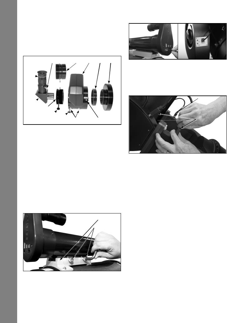
D Press the computer control panel power switch to OFF, if necessary. Remove the AutoStar II handbox and the AutoStar II coil cord from the packing materials. Plug one end into the HBX port of the telescope’s computer control panel (Fig. G) and plug the other end into the coil cord port on the AutoStar II handbox.
On/Off switch
HBX port
Figure G. The LX600 control panel).
E Remove the travel screw on the rear OTA Use the provided hex key to remove the travel screw (the position of the travel screw will vary by OTA model) (Fig. H). DO NOT OPERATE THE FOCUS KNOB BEFORE REMOVING THE SCREW or you will damage your telescope. Place the provided black plastic cap in the hole left by the travel screw. Retain the travel screw for use in future shipments.
Travel screw 
Figure H. Remove the travel screw before operating the focuser. Return the travel screw before shipping the telescope.
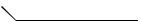
F Attach the 1.25" Diagonal Remove the dust cap from the rear cell of the telescope. Thread the eyepiece holder into the rear cell thread. Slide the diagonal prism into the eyepiece holder and lock in place by turning the thumbscrew to a firm feel.
Place the Super Plössl 26mm eyepiece into the diagonal prism and tighten the attachment thumbscrew to a firm feel only.
G Attach the Microfocuser (Optional Accessory) Remove
 Eyepiece
 Thumbscrews
 Diagonal prism
 Rear cell port
Qucik Start
7
Quick Start
the dust cap from the rear cell port (A) of the telescope (Note: Telescope not shown for clarity). Thread the microfocuser adapter (B) into the rear cell port thread. Slide the microfocuser (C) over the microfocuser adapter and tighten the three hex screws on the microfocuser (K) using the provided hex keys.

OR


Figure I. Attaching the optional microfocuser.
1.25" Diagonal Prism Users: If using the 1.25" diagonal prism (G), slide the 1.25" adapter (D) into the microfocuser. Line up the thumbscrew into the groove in the microfocuser. Slide the 1.25" diagonal prism into the adapter (D). Tighten the adapter thumbscrew (H) to a firm feel only. Tighten the microfocuser thumbscrews (I) to a firm feel only.
2.0" Diagonal Mirror Users: If using the optional 2.0" diagonal mirror, slide the mirror directly into the microfocuser (C). Tighten the microfocuser thumbscrews (I) to a firm feel only.
Dovetail bracket
 taining bolts
H Attach the StarLock assembly. Loosen the two retaining bolts on the StarLock dovetail bracket with the provided hex key. Slide the StarLock unit fully into the saddle plate. Tighten the retaining bolts to a firm feel only.
I Attach the StarLock cable. The StarLock cable has a small connector on one end and a larger connector on the other end. Plug the smaller connector into the“StarLock Telescope Connection” port on the StarLock unit and the larger connector into the “StarLock” port located on the fork arm.
Fork arm jumper cable — other end is obscured
 Fork arm jumper
J Connect the two (2) jumper cables that bridge the OTA and the telescope base. These jumpers are non-directional and identical on each fork arm. Secure the connectors to the receptacle by tightening the knobs on both sides of the plug. Finger tight, do not over tighten.
1)Remove the dust covers from the ends of the telescope tube and the narrow and wide angle tubes of the StarLock.
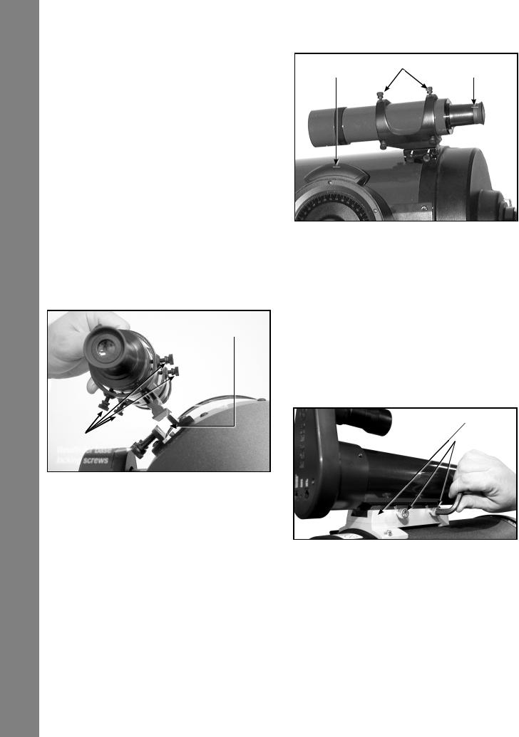
1!Mount and align the viewfinder. To assemble and align the viewfinder perform the following during the daytime:
1.Assemble the viewfinder by attaching all included thumbscrews onto the viewfinder bracket and insert the 8X50 viewfinder into the bracket. Tighten the thumbscrews to a firm feel only so the 8x50 optical tube is roughly centered in the middle of the bracket.
2 . Slide the viewfinder bracket into its mounting assembly on the OTA. To secure the viewfinder to the mounting assembly, tighten the two thumbscrews to a firm feel only. Remove the viewfinder dust cover.
3.Loosen the RA and DEC clutches. Point the telescope at some well-defined and stationary land object at least 200 yards distant, such as
8
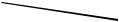
B C
RA lock
DEC lock
Figure J. The RA and DEC locks.
the top of a telephone pole or street sign. Center the object in the telescope eyepiece. Re-tighten the RA and DEC clutches.
4.With the object centered in the telescope eyepiece, look through the viewfinder and loosen or tighten, as appropriate, one or more of the viewfinder collimation screws until the viewfinder crosshairs are precisely centered on the object you previously centered in the telescope eyepiece. Twist the rear section near the eyecup clockwise or counter-clockwise to bring the object into clear focus.
5.Check this alignment on a celestial object, such as the Moon or a bright star, and make any necessary refinements.
1@Balance the OTA. Rotate the OTA so that it is parallel to the ground plane. Locate the counterweight (Fig. K, 3) and loosen its locking hex screw just enough so that the counterweight can
Depending on the optional accessories you attach, additional weights may need to be purchased.
1#Tighten, to a firm feel only, the RA and DEC locks.
1$Press the Power Switch on the computer control panel to the ON position. The copyright message lights on AutoStar II’s LCD display.
1%“Press 0 to Align or Mode for Menu” displays. You can use the Arrow keys to slew (move) the telescope up, down, right, or left. To change the telescope’s slew speed, press the Speed key and then the Number keys. “9” is the fastest speed and “1” is the slowest speed. See page 20 for more details, or you can Press “0” to begin Automatic Alignment. See page 21 for more information.
B Counter-
weight rail
C Counterweight 
hex screw
D Counterweight
Figure K. OTA counterweight assembly.
slide easily along the counterweight rail. While maintaining a hold on the OTA, lightly loosen the DEC Lock (Fig.J, 2) so that the OTA rotates freely. With your free hand move the counterweight until the OTA balances; favoring neither front nor back. Tighten the counter weight hex screw to secure.
Note that the counterweight provides adjustment to balance the OTA equipped with the standard factory accessories.
Quick Start
9

LX600 Features
LX600 FEATURES
B
C 3( D
E
F
G
H
I
J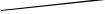
(Not
1)
1!
(Not shown)
1@
3!
2$ |
1(
1*
(Not shown)
 1&
1&
1^
1$  1#
1#
|
|
B Eyepiece |
1) RA slow-motion control |
C Eyepiece thumbscrew |
1! RA setting circle |
D 1.25" diagonal prism |
1@ RA lock |
E Diagonal prism thumbscrew |
1# Computer Control Panel (see page 12 for more information) |
F Rear cell port |
1$ Autostar II holder |
G Two-speed focus knob |
1% Fork handles |
H Fork arms |
1^ DEC slow-motion control |
I Battery compartments |
1& DEC lock |
j Travel screw |
1* Dust cover |
Figure 1(a): LX600 Key Features - Right View; Control panel (inset)
10
|
|
|
|
|
|
|
2( |
|
|
|
|
|
|
|
|
2) |
|
|
|
3) |
|||
|
|
|
2# |
||||
|
|
|
|
|
|
||
2! |
|
|
|
|
|
|
|
|
|
|
|
|
|
||
2@ |
|
|
|
|
|
||
|
|
|
2^ |
||||
2% |
|
|
|
|
|
||
|
|
|
|
|
|
||
|
|
|
|
|
2& |
||
|
|
|
|
|
|
||
3^ |
2* |
3& |
|
1% |
|
3( |
|
3* |
|
|
||
3% |
|
|
|
3@ |
||
|
|
|
||||
|
|
|
|
|
||
|
|
|
|
|
|
3# |
|
|
|
|
|
|
|
|
|
|
|
|
3$ |
|
1( Optical tube (see page 10)
2) DEC setting circle
2! Viewfinder collimation screws
2@ 8 x 50 viewfinder
2# GPS receiver
2$ Tube adapters (see page 10)
2% Counterweight(s)
2^ Counterweight hex screw
2& Counterweight rail
2* AutoStar II handbox |
3^ Fork Arm Jumper Cables |
|
2( StarLock assembly |
3& Fork Arm Connecting Plates |
|
3) StarLock dovetail bracket |
3* Connecting Plate Bolts (4 per fork |
|
3! StarLock retaining bolts (see page |
arm) |
|
3( StarLock Cable |
||
10) |
||
3@ Threaded rod |
|
|
3# Spreader bar |
|
|
3$ T-handle tension knob |
|
|
3% X-Wedge (see Appendix F) |
|
Figure 1(b): LX600 Key Features - Left View
LX600 Features
11

LX600 Features
LX600 FEATURES
The Meade LX600 ACF models are extremely versatile, highperformance telescopes for imaging and visual use. With pushbutton controls, precision GPS alignment, true-level and North electronic sensors, StarLock automatic guiding and ultraprecise pointing, automatic tracking of celestial objects, and a library of 145,000+ objects in the AutoStar II database, the LX600 ACF models offer unmatched state-of-the-art performance.
Observe or image the rings of the planet Saturn from a distance of 800 million miles or focus beyond the Solar System on ancient star clusters, remote galaxies, and stars recently discovered to have planets orbiting about them. Meade LX600 ACF telescopes are capable of growing with your interest and can meet the requirements of the most demanding advanced observer.
Caution: Using products other than standard Meade accessories may cause damage to the telescope’s internal electronics and may void the Meade warranty.
B Eyepiece: Place the Series 4000 26mm Plössl eyepiece into the 90° diagonal prism (Pg. 10, Fig. 1, 1) and tighten in place with the eyepiece thumbscrew (Fig. 1, 2). The eyepiece magnifi es the image collected in the optical tube.
CEyepiece Thumbscrew: Tightens the eyepiece (Fig. 1, 2) in place. Tighten to a firm feel only.
D1.25" Diagonal Prism: Provides a more comfortable right angle viewing position.
EDiagonal Prism Thumbscrew: Tightens the diagonal prism in place. Tighten to a firm feel only.
FRear Cell Port: The diagonal prism slides into this port.
GTwo-speed Focus Knob: 2-Speed Crayford-style focusing system moves the telescope’s primary mirror in a finely-controlled motion to achieve precise image focus. LX600 telescopes can be focused on objects from a distance of about 100 ft to infinity. Rotate the focus knob clockwise to focus on distant object.
HFork Arms: This heavy-duty mount holds the optical tube securely in place.
IBattery Compartments: Insert four user-supplied C-cell batteries into each compartment (one compartment on each fork arm; eight batteries total).
JTravel Screw: Locks down the primary mirror during transportation.
1)Right Ascension (RA) Slow-Motion Control: When not using AutoStar electronic control, make fine adjustments in the Right Ascension, i.e. the horizontal axis, by turning this control with the RA lock in the unlocked position. Set the RA lock to a “partially locked” position to create a comfortable drag for the RA slow-motion control.
Caution: Do not operate the RA or DEC slow-motion controls with the locks in the fully locked position, as such operation may result in damage to the internal gear system and also cause you to lose alignment.
1!Right Ascension (RA) Setting Circle: See Appendix E, page 57, for detailed information.
1@ Right Ascension (RA) Lock: Controls the manual horizontal rotation of the telescope. Turning the RA lock counterclockwise unlocks the telescope, enabling it to be freely rotated by hand about the horizontal axis. Turning the RA lock clockwise locks the telescope, prevents the telescope from being rotated manually, and engages the horizontal motor drive for AutoStar II operation.
1# Computer Control Panel (see Pg. 10, Fig. 1 inset):
A.ON/OFF Switch: Turns the computer control panel and AutoStar II ON or OFF. The red power indicator LED next to the switch illuminates when power is supplied to the AutoStar II handbox,
the optional microfocuser and to the telescope’s motor drives (the LED can be turned off in the Panel Light menu; see page 32).
B.12vDC Power Connector: Provides a connection so that the telescope assembly may be powered from a standard 115/240v AC home outlet using the optional Universal Power Adapter (product# 07584) or the optional 12v DC #607 Cigarette Lighter Adapter (product# 07043). See Optional Accessories, page 44.
C.Focus Port: (An additional focus port is located on the fork arm). Plug the optional microfocuser into this port. Control the microfocuser through the AutoStar II menus. See Hot Button Menus, page 36.
D.Reticle Port: Plug the optional reticle eyepiece cable into this port. Control the reticle through the AutoStar II menus. See Hot Button Menus page 36. Also see OPTIONAL ACCESSORIES, page 44.
Note: See the instruction sheets that are included with the focuser and the reticle for more details.
E.12vDC Output: (An additional 12vDC power output is located on the fork arm) Use the 12vDC output to power telescope accessories.
F.Handbox (HBX) Port: Plug the AutoStar II coil cord into this port.
G.RS232 Port: Provides a connection with a PC
12

and for current and future Meade accessories. Your PC can control your LX600 ACF telescope using the supplied AutoStar Suite software for custom applications. Go to the Meade website (www.meade.com) to download the latest serial commands and device pinouts.
H.Auxillary Autoguider Port: If you wish to use an add-on autoguider in place of the integrated StarLock, plug the autoguider cable into this port. See the instruction sheet that came with your autoguider for more information.
1$Tiltable AutoStar II Holder: Attach to fork handles (see 1% below) or X-Wedge. Holds your handbox in a convenient location.
1%Fork Handles: Use to lift optical tube assembly or to rotate the telescope when attached to the tripod.
Important After the telescope is aligned do not use the RA or DEC manual slow motion controls or alignment will be lost and the telescope will need to be realigned.
1^Declination (DEC) Slow-Motion Control: Make fine adjustments in declination (altitude) by turning this control. In order for this control to operate properly, power must be off.
1&DEC Lock: Controls the manual vertical movement of the telescope. Turning the DEC lock counterclockwise unlocks the telescope, enabling it to be freely rotated by hand about the vertical axis. Turning the DEC lock clockwise (to a firm feel only) prevents the telescope from being moved manually, but engages the vertical motor drive for AutoStar II operation.
Caution: When loosening the DEC lock, be sure to support the optical tube (Fig. 1, 19). The weight of the tube could cause the tube to swing through the fork arms suddenly.
1*Dust Cover: Gently pry the dust cover from the front lens of the telescope.
Note: The dust cover should be replaced after each observing session and the power turned off to the telescope. Verify that any dew that might have collected during the observing session has evaporated prior to replacing the dust cover.
1(Optical Tube: The main optical component that gathers the light from distant objects and brings this light to a focus for examination through the eyepiece.
2)Declination (DEC) Setting Circle: See Appendix E, page
57, for detailed information.
2!Viewfinder Collimation Screws: Use these six screws to adjust the alignment of the viewfinder.
2@8 x 50mm Viewfinder: A low-power, wide-fi eld sighting scope with crosshairs that enables easy centering of objects in
the telescope eyepiece.
2#GPS Receiver: Receives information transmitted from Global Positioning System satellites. See page 24 for more information.
2$Tube Adapters: The optical and mechanical axes of the LX600 telescope have been carefully aligned at the factory to ensure accurate object pointing. Do not loosen or remove the optical tube assembly from the tube adapters. The resulting misalignment of the axes will result in inaccurate pointing of the telescope in the GO TO mode.
2%StarLock Counterweight(s): Precisely counter balance the StarLock assembly and optional accessories by moving this weight.
2^StarLock Counterweight Hex Screws: Tighten to secure the counterweight in place.
2&StarLock Counterweight Rail: Slide the StarLock counterweight along this rail to achieve optimum balance.
2*AutoStar II Handbox: The LX600 user interface. Use the Handbox to command the LX600 to automatically slew to any object in the night sky. See pages 27 thru 36 for a description of features.
2(StarLock Assembly: Integrated autoguiding unit made up of the StarLock narrowfi eld OTA and sensor, used for highprecision guiding, and the StarLock widefi eld OTA and sensor, used in alignment and ultra-precise pointing.
3)StarLock Dovetail Adapter: Attaches StarLock to the telescope mount.
3!StarLock Retaining Bolts: Secures the StarLock assembly to the dovetail adapter.
3@Tripod Threaded Rod: Secures the LX600 mount to the tripod.
3#Tripod Spreader Bar: Holds the LX600 mount and tripod legs in place.
3$Tripod T-handle Tension Knob: Use to apply tension to the tripod spreader bar.
3%X-Wedge: See Appendix F for details.
3^Fork Arm Jumper Connector: Bridges the break between OTA and Telescope base.
3&Fork Arm Connecting Plate: Mates OTA to base for easier assembly. Four connecting screws per side(See Appendix D).
3*Connecting Plate Bolt: Used to secure the OTA to Telescope base. Four (4) connecting screws per side.
LX600 Features
13
AutoStar II Features
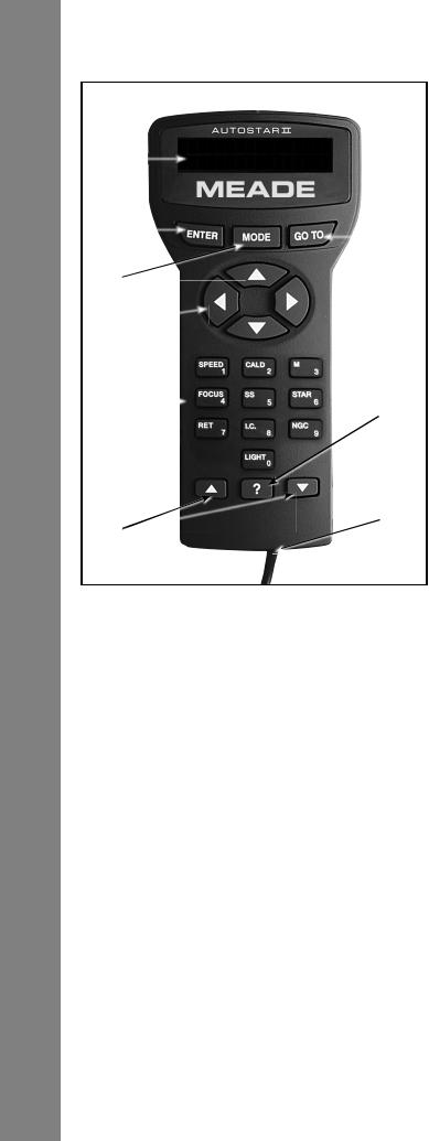
AUTOSTAR II FEATURES
 1!
1!
B

C


 E
E D
D
F
G I
I
H J
J 
 1)
1)
Figure 2: The AutoStar II handbox
Tour the Cosmos with Just the Push of a Button
Control of the LX600 ACF telescope models is through the operation of the standard AutoStar II system. Nearly all functions of the telescope are accomplished with just a few pushes of AutoStar II’s buttons.
Because the AutoStar II system uses fl ash (rewritable) memory, your system will be able to grow when new features and enhancements become available. Download the latest satellite data, star and object catalogs, tours, serial commands list and software revisions, directly from the Meade website (www. meade.com). To learn about downloading updates see Page 35. Requires the optional #507 Cable Connector Kit (product# 07047.
See OPTIONAL ACCESSORIES, page 44).
Some of the major features of the AutoStar II system are:
■Automatically move the telescope to any of the more than 145,000 objects stored in the object library, including:
Library |
Number of Objects |
|
New General Catalog (NGC) |
........................ |
7,840 |
Index Catalog (IC)........................................ |
|
5,386 |
Messier Catalog (M)........................................ |
|
110 |
Caldwell Catalog............................................ |
|
109 |
Named Objects .............................................. |
|
227 |
Herschel Catalog ........................................... |
|
400 |
Abell Catalog of Galaxy Clusters ................. |
2,712 |
|
Arp Catalog of Irregular Galaxies ................... |
645 |
|
Uppsala Galaxy Catalog ............................ |
|
12,940 |
Morphological Catalog of Galaxies............ |
12,939 |
|
General Catalog of Variable .............Stars |
28,484 |
|
SAO ........................................................... |
|
17,191 |
Hipparcos Star Catalog.............................. |
|
17,325 |
■Take a guided tour of the best celestial objects to view on any given night of the year.
■Control your LX600 ACF with your PC using an RS232 interface.
■Align your telescope automatically using GPS (Global Positioning System), Level North sensors and StarLock.
■Access a glossary of astronomical terms.
■Mount the telescope in the “Alt-az” mode (altitude-azimuth, or vertical-horizontal), or polar mode with the optional X-Wedge, for fully automatic tracking, GoTo pointing and guiding on celestial objects.
The AutoStar II system provides control of virtually every telescope function. The AutoStar II handbox has soft-touch keys designed to have a positive feel. The LCD (Liquid Crystal Display) is backlit with red LEDs (Light Emitting Diodes) for easy viewing in the dark. The backlit display, key arrangement, and sequential menu structure make AutoStar II extremely user friendly.
B2-Line LCD Display: This screen displays AutoStar II’s menus and information about the telescope.
•Top line: Lists the primary menu.
•Bottom line: Displays other menus that may be chosen, menu options, telescope status, or information about a function that is being performed.
14

cENTER Key: Press to go to the next menu level or to choose an option in a menu. The ENTER key is similar to the RETURN or ENTER key on a computer. See NAVIGATING AUTOSTAR II, page 30 and AutoStar II Menu Tree, page 29.
dMODE Key: Press to return to the previous menu or data level. The top menu level is “Select Item”. The MODE key is similar to the ESCAPE key on a computer.
Note: Pressing MODE repeatedly while in the “Select Item” level moves AutoStar II to the topmost screen: “Select Item: Object”.
Note: If MODE is pressed and held for two seconds or more, information about the telescope’s status displays. When the status displays, press the Scroll keys (Fig. 2, 7) to display the following information:
•Right Ascension and Declination (astronomical) coordinates
•Altitude (vertical) and Azimuth (horizontal) coordinates
•Local Time and Local Sidereal Time (LST)
•Timer and Alarm Status
•Date
•Site coordinates
•Battery status
Press MODE again to return to the previous menu.
eGO TO Key: Press to slew (move) the telescope to the coordinates of the currently selected object. While the telescope is slewing, the operation may be aborted at any time by pressing any key except GO TO. Pressing GO TO again resumes the slew to the object. Also, press during the alignment or GO TO procedures to activate a “spiral search”. To learn more about the GO TO function and performing a spiral search see Page 23.
fArrow Keys: The Arrow keys have several functions. Press an Arrow key to slew the telescope in a specifi c direction (up, down, left, and right), at any one of nine different speeds. See Slew Speeds, page 20. Use the Up and Down Arrow keys to move the telescope vertically up and down. The Left Arrow key rotates the telescope horizontally counterclockwise, while the Right Arrow key rotates it clockwise (unless reversed for Southern Hemisphere use).
Also, use the Arrow keys to scroll through numbers 0 through 9 and the alphabet. The Down Arrow key begins with the letter “A”, the Up Arrow key begins with digit “9”.
Additionally, use the Arrow keys to to move the cursor across the display: Use the Right or Left Arrow key (Fig. 2, 5) to move the cursor from one number to the next in the display.
gNumber Keys: Press to input digits 0 to 9. Each Number key also has a specifi c function, which is printed on each key (these are commonly known as “hot buttons”—see page 36):
1SPEED: Changes the slew speeds. To operate, press Speed and then a Number key (1 is the slowest speed, 9 is highest speed). To learn about changing slew speed see Page 20.
2CALD (Caldwell): Press to display the Caldwell catalog on the AutoStar II handbox.
3M (Messier): Press to display the Messier catalog library.
4Focus: Press to display the Focus Control menu.
5SS: Press to display the Solar System library.
6STAR: Press to display the Star library.
7RET (Reticle): Press to display the StarLock Control menu. To learn about the StarLock menu see Page 32.
8IC: Press to display the Index Catalog library.
9NGC (New General Catalog): Press to display the NGC catalog library.
0LIGHT: Press to turn on and off the red utility light on the top of the hand-box.
hScroll Keys: Press to access options within a selected menu. The menu is displayed on the first line of the screen. Options in the menu are displayed, one at a time, on the second line. Press the Scroll keys to move through the options. Press and hold a Scroll key to move quickly through the options.
The Scroll keys also control the speed of text scrolling on the AutoStar II display. When text is scrolling, press and hold the Up Scroll key for a faster display speed and the Down Scroll key for a slower display speed.
i? Key: Press to access the “Help” file. “Help” provides on-screen information on how to accomplish whatever task is currently active.
Press the ? key and then follow the prompts on the display to access details of AutoStar II functions in the Help feature. The Help system is essentially an on-screen instruction manual.
If you have a question about an AutoStar II operation, e.g., INITIALIZATION, ALIGNMENT, etc., press the ? key and follow
AutoStar II Features
15

AutoStar II Features
the directions that scroll on the second line. When satisfi ed with the Help provided, press MODE to return to the original screen and continue with the chosen procedure.
Tip: When an astronomical term appears in [brackets], press ENTER for a definition or more detailed information. Press MODE to return to the scrolling AutoStar II Help display.
If a celestial object’s name appears in brackets (and your telescope is aligned), press ENTER and then GO TO to slew the telescope to the object.
jCoil Cord Port: Plug one end of the AutoStar II coil cord (Pg. 14, Fig. 2, 10) into this port located at the bottom of the AutoStar II handbox.
1)Coil Cord: Plug one end of the AutoStar II coil cord into the HBX port (Pg 10, Fig 1 inset, F) of the computer control panel of the telescope and the other end into the AutoStar II coil cord port. See #9 above.
1!Utility Light: Use this built-in red light to illuminate star charts and accessories without disturbing your eye’s adaptation to darkness. Press “0” to turn the light on and off.
16
GETTING STARTED
Parts Listing
Getting the telescope ready for first light requires only a few minutes. When first opening the packing box, note carefully the following parts:
■LX600 ACF telescope with fork mount system
■AutoStar II handbox and interface coil cord; handbox holder
■8 x 50mm viewfinder assembly
■Eyepiece holder and 1.25" diagonal prism
■Series 4000 26mm Super Plössl eyepiece
■OTA Counterweight(s)
■DEC Jumper cables (2)
■Anti-vibration pads (3)
■507 Connecting Cable
■Variable height Giant Field Tripod and mounting base, threaded rod with T-handle tension knob, spacer cone and c-clip, and spreader bar
■Set of hex keys
■StarLock unit with cable
■Instructional Manual and Software DVD.
How to Assemble Your Telescope
Assembly of the LX600 ACF telescope requires eight C-cell (usersupplied) batteries or the optional Universal AC Power Adapter (product# 07584) connected to a standard 115v home outlet or to an optional #607 Cigarette Lighter Adapter (see OPTIONAL ACCESSORIES, page 44). Plug an adapter into the 12vDC In port of the computer control panel (Fig. 1, 13B).
Note that the LX600 features split fork arms allowing you the option of breaking the telescope down into to two, easier to maneuver units. See Appendix D, Page 55 for details.
1.Position the telescope: Start by turning the DEC lock (Pg. 10, Fig. 1, 17) counterclockwise to unlock the the optical tube (Fig. 1, 19). Next, move the optical tube through the fork arms to the position depicted in Fig. 1 and turn the DEC lock clockwise to a firm feel to relock the position of the optical tube.
2.Install batteries: Remove the battery compartment covers (Fig. 1, 8) and carefully remove the battery holders, being mindful of the connector wires. Insert four user-supplied
C-cell batteries into each battery holder, oriented as shown on the diagram on the battery slots inside the battery holder. Return the battery holders to their respective compartments and
replace the covers.)
3.Plug in the AutoStar II handbox: Be certain that the power switch on the computer control panel (Fig. 1, 13A) is in the OFF position. Plug the coil cord of the AutoStar II handbox into the HBX port (Fig. 1, 13F).
Note: The AutoStar II handbox does not require batteries. The telescope supplies its power.
4.Remove the dust cap from the rear cell of the telescope. Thread the eyepiece holder into the rear cell thread. Slide the diagonal prism into the eyepiece holder and lock in place by turning the thumbscrew to a firm feel.
5.Insert eyepiece: Remove the Series 4000 26mm Super Plössl eyepiece (Fig. 1, 1) from its container and place it in the diagonal prism (Fig. 1, 3). Tighten the eyepiece holder thumbscrew (Fig. 1, 2) to a firm feel only.
6.Remove the travel screw. The LX600 is shipped with a travel screw in place to protect the primary mirror during shipping. Use the provided hex key to remove the screw. Replace the screw with the provided plastic cap. DO NOT ADJUST THE FOCUS KNOB BEFORE REMOVING THE TRAVEL SCREW OR DAMAGE TO YOUR TELESCOPE WILL OCCUR.
7.Remove dust cover: Remove the dust cover (Fig. 1, 18) from the optical tube assembly (Fig. 1, 19) by gently prying it off.
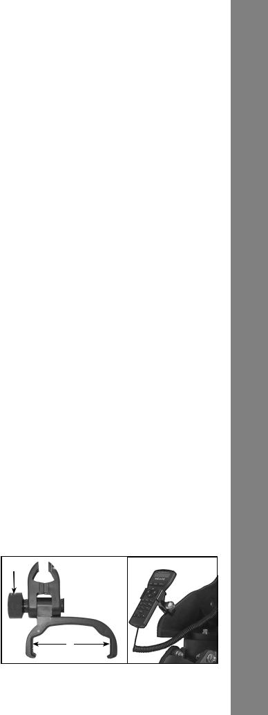
8.Attach the handbox holder: Remove the handbox holder from the plastic bag. If necessary, loosen the lock knob (Fig. 3a, A) and place the clamp (Fig. 3a, B) about one of the fork arm handles (Fig. 1, 15). Tighten the lock knob to a firm feel. Slide the AutoStar II handbox into the holder (Fig. 3a, C). You may also snap the

Figure 3a: Handbox holder: (A) Lock knob; (B) Clamp; (C) Holder. Fig. 3b: Handbox holder attached to fork arm handle.
Getting Started
17
Getting Started
handbox into the holder: Slide one side of the handbox into the holder and then firmly press the other side of the handbox into the holder until it snaps in place. Adjust the tilt of of the holder by loosening the lock knob and then moving the holder clamp to the desired angle. Retighten the lock knob.
9.Mounting and Adjusting the Viewfinder. To align the viewfinder, perform steps A through
Ebelow during the daytime; perform step F at night.
A.Slide the track on the bottom of the viewfinder into the slot in the viewfinder mounting assembly. To secure the viewfinder to the mounting assembly, tighten the two thumbscrews (Fig. 9) to a firm feel only.
B.If you have not already done so, insert the
Mounting slot
 Track
Track
Thumbscrews
Viewfi nder base  locking screws
Fig. 4. Viewfi nder assembly
26mm eyepiece into the diagonal prism.
C. Unlock the RA (Pg. 10, Fig. 1, 12) and DEC (Fig. 1, 17) locks so that the telescope moves freely on both axes.
D.Point the telescope at some well-defined and stationary land object at least 200 yards distant, such as the top of a telephone pole or street sign. Center the object in the telescope eyepiece. Retighten the RA and DEC locks.
E.Look through the viewfinder eyepiece (Fig.
5) and loosen or tighten, as appropriate, one or more of the viewfinder collimation screws (Fig.
GPS |
Collimation screws |
Viewfi nder |
receiver |
|
eyepiece |
Fig. 5. Viewfi nder collimation screws and eyepiece
5) until the viewfinder crosshairs are precisely centered on the object you previously centered in the telescope eyepiece.
F. Check this alignment on a celestial object, such as the Moon or a bright star, and make any necessary refinements, using the method outlined in steps C through E.
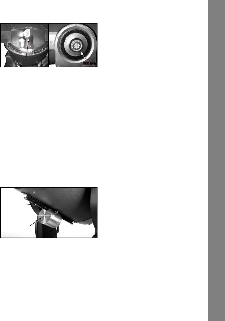
10.Mounting the StarLock unit. Mount the StarLock unit by sliding it into the StarLock dovetail adapter on the top of the OTA. The unit slides into the adapter from back to front.
Dovetail bracket
 taining bolts
Mount StarLock
Once positioned, secure the unit by tightening the thumbscrews until they are snug. Do not overtighten. Remove both dustcovers from the lenses of the StarLock.
11.Attach the StarLock cable. The StarLock cable has two distinct connections, a four-pin and a six-pin. Make sure that you plug the four-pin end into the “StarLock Telescope
18
Connection” port on the back of the StarLock unit, and the six-pin into the “StarLock” port on the fork arm.
11.Attach the DEC jumper cable. LX600 features split fork arms. In order to make electric connection between the two portions you must install the jumper cables on the left and right sides. .
Choosing an Eyepiece
A telescope’s eyepiece magnifi es the image formed by the telescope’s main optics. Each eyepiece has a focal length, expressed in millimeters, or “mm”.
The smaller the focal length, the higher the magnifi cation. For example: An eyepiece with a focal length of 9mm has a higher magnifi cation than an eyepiece with a focal length of 26mm.
Your telescope comes |
supplied |
|
||
with |
a 26mm |
Plössl |
eyepiece |
|
which gives a wide, comfortable |
|
|||
Series 4000 26mm Super |
||||
fi eld |
of view |
with |
high |
Plössl eyepiece |
image resolution.
Low power eyepieces offer a wide fi eld of view, bright, highcontrast images, and eye relief during long observing sessions. To find an object with a telescope, always start with a lower power eyepiece such as the 26mm Plössl. When the object is located and centered in the eyepiece, you may wish to switch to a higher power eyepiece to enlarge the image as much as practical for prevailing seeing conditions. For information about optional eyepieces for the your telescope, see OPTIONAL ACCESSORIES, page 44.
The power, or magnifi cation of a telescope is determined by the focal length of the telescope and the focal length of the eyepiece being used (an eyepiece’s focal length is printed on the side of the eyepiece). To calculate eyepiece power, divide the telescope’s focal length by the eyepiece’s focal length.
For example: A 26mm eyepiece is supplied with LX600 ACF models. The focal length of the 14" f/8 LX600 ACF is 2845mm (see Specifications, pages 49 and 50).
Eyepiece Power = Telescope focal length ÷ Eyepiece focal length Eyepiece Power = 2845mm ÷ 26mm
Eyepiece Power = 109
The eyepiece power, or magnifi cation is therefore 109x.
Note: For a list of magnification ratings of the eyepieces
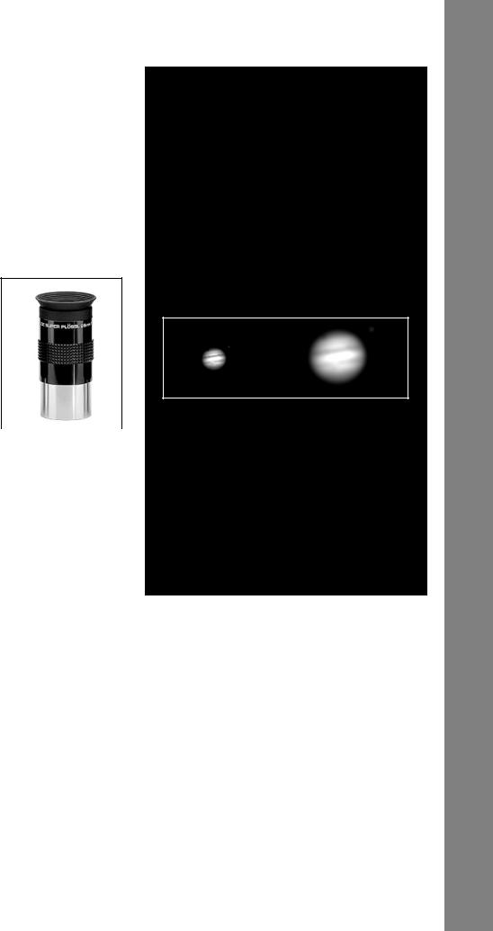
Too Much Power?
Can you ever have too much power? If the type of power you’re referring to is eyepiece magnification, yes, you can! The most common mistake of the beginning observer is to “overpower” a telescope by using high magnifications which the telescope’s aperture
and atmospheric conditions cannot reasonably support. Keep in mind that a smaller, but bright and well-resolved image is far superior to one that is larger, but dim and poorly resolved. Powers above 400X should be employed only under the steadiest atmospheric conditions.
Jupiter; examples of the right amount of magnifi cation (left) and too much magnifi cation (right).
AutoStar II can calculate the best eyepiece for you to use. Try out the “Eyepiece Calc” feature in the Utilities menu.
Most observers should have three or four additional eyepieces to achieve the full range of reasonable magnifications possible with the LX600 ACF telescopes. See OPTIONAL ACCESSORIES, page 44.
available for the LX600 ACF telescopes, see OPTIONAL ACCESSORIES, page 44.
Note: Seeing conditions vary widely from night-to-night and site-to-site. Turbulence in the air, even on an apparently clear night, can distort images. If an image appears fuzzy and ill-defined, back off to a lower power eyepiece for a more well-resolved image (see above example of Jupiter).
Getting Started
19

Observing
OBSERVIING
Observing Using AutoStar II’s
Arrow Keys
You may observe land and astronomical objects using AutoStar II’s Arrow keys to move the telescope.
1.Tighten the RA and DEC locks (Fig. 1, 12 and 17).
2.Verify that AutoStar II is properly connected to your telescope. See Quick Start, page 6.
3.Flip the telescope power switch to the ON position.
The AutoStar II screen is activated and a copyright message displays briefly, followed by a short beep. Then AutoStar II takes a few moments to start up the system.
4.After the Autostar II has finished startup, "Press Mode for Menu or 0 to Align displays". Press Mode.
5.Press the Mode key several times until Setup Item: Object displays.
6.The Arrow keys are now activated. Press the Arrow keys (Pg. 14, Fig. 2, 5) to slew (move) the telescope up, down, right, or left.
7.Press the Speed key (Number key “1”) and then a Number key (Fig. 2, 6) to change the
telescope’s slew speed (“1” is the slowest speed, “9” is highest speed).
8.Use the viewfinder (Fig. 1 , 22) to locate an object and practice using the AutoStar II’s Arrow keys to center the object in the telescope’s field of view.
Warning: Do not look through the telescope’s eyepiece or viewfinder while it is rapidly moving. Children should always have adult supervision while observing.
Slew Speeds
AutoStar II has nine slew speeds that move the optical tube at rates that are directly proportional to the sidereal rate and have been calculated to accomplish specifi c functions. Press the Speed key (Number key “1”) and then press a Number key to change the slew speed, which is shown for about two seconds on AutoStar II’s display.
The nine available speeds are:
Number Key 1= |
1x = |
Guide Rate, programmable |
Number Key 2= |
2x = |
2 x sidereal (0.5 arc-min/sec |
|
|
or 0.008°/sec) |
Number Key 3= |
8x = |
8 x sidereal (2 arc-min/sec |
|
|
or 0.033°/sec) |
Number Key 4= |
16x = |
16 x sidereal (4 arc-min/sec |
|
|
or 0.067°/sec) |
Number Key 5= |
64x = |
64 x sidereal (16 arc-min/sec |
|
|
or 0.27°/sec) |
Number Key 6= |
128x = |
30 arc-min/sec or 0.5°/sec |
Number Key 7= |
1.5° = |
90 arc-min/sec or 1.5°/sec |
Number Key 8= |
3° = |
180 arc-min/sec or 3°/sec |
Number Key 9= |
Max = |
480 arc-min/sec or 8°/sec) |
Speeds 1, 2, or 3: Best used for fine centering of an object in the fi eld of view of a higher power eyepiece, such as a 12mm or a 9mm eyepiece.
Speeds 4, 5, or 6: Enable centering of an object in the fi eld of a low-to-moderate power eyepiece, such as the standard Super Plössl 26mm.
Speeds 7 or 8: Best used for rough centering of an object in the viewfinder.
Speed 9: Moves the telescope quickly from one point in the sky to another.
Astronomical Observing
Used as an astronomical instrument, your telescope has many optical and electromechanical capabilities. It is in astronomical applications where the high level of optical performance is readily visible. The range of observable astronomical objects is limited only by the observer’s motivation.
To Track an Object Automatically
As the Earth rotates beneath the night sky, the stars appear to move from East to West. The speed at which the stars move is called the sidereal rate. You can setup your telescope to move at the sidereal rate so that it automatically tracks (follows) the stars and other objects in the night sky. If the telescope is not tracking an astronomical object, the object will drift out of the eyepiece fi eld of view. The tracking function automatically keeps an object centered in the telescope’s eyepiece.
To automatically track objects, you need to learn how the AutoStar II keypad operates in order to move through its menus. You will need to initialize and align your telescope.
20
Moving Through AutoStar II’s Menus
The AutoStar II database is organized in levels for quick and easy navigation.
■Press ENTER (Pg. 10, Fig. 2, 2) to go deeper into AutoStar II’s menu levels.
■Press MODE (Fig. 2, 3) to move back toward the top menu level.
■Press the Scroll keys (Fig. 2, 7) to move up and down through the options available for each level.
■Press the Arrow keys (Fig. 2, 5) to enter characters and digits. The Arrow keys are also used to move the telescope.
■Use the Number keys (Fig. 2, 6) to enter digits.
Automatic Alignment for Alt-Az Mounted Telescopes
AutoStar II offers four methods of altazimuth (alt-az) alignment; this section describes how to initialize and align your telescope using Automatic Alignment. (For a description of the other altaz alignment methods, see page 41. For information about equatorial (polar) alignment, see the next section, Appendix D and Appendix E).
To prepare your telescope for Automatic Alignment:
1.Tighten the RA and DEC locks (Pg. 10, Fig. 1, 12 and 17).
2.Verify that AutoStar II is properly connected to your telescope. See How To Assemble Your Telescope, page 17.
3.Flip the telescope power switch to the ON position.
When you slide the On/Off switch to “On” on your telescope’s computer control panel, a version screen briefly appears, followed by “Welcome
to AutoStar”.
4.“Press 0 to align or Mode for Menu” displays. Press “0” to begin Automatic Alignment. (If you wish to choose a manual alignment method, keep pressing Mode to go through the menus to find other alignments.)
Note: AutoStar II initializes the Smart Drive if it has been turned “On,” has been previously selected, PEC training has been performed and you have “parked” the telescope. If you have
parked it, AutoStar II will remember its position on the worm gear. If you do not park the scope and turn it off, it will not remember its position.
See Parking the Telescope, page 32 and PEC Training, page 43.
5.“Automatic Alignment” displays. The system now performs the following routines (press any AutoStar II key to abort Automatic Alignment) :
Caution: As the telescope performs the following operations, it will swing and rotate. Keep a safe distance from the telescope. The telescope now finds the level and tilt position of the telescope, and also detects where true North is. It may not actually level or tilt the telescope or point to North — it is just detecting these positions. This may take a minute or two.
a.Finds the home position. Moves the telescope to find the “home” position. When the home position is found, the system knows the limiting positions of the telescope and can avoid tangling cables and over-rotating the telescope.
b.Detects “level” position of the telescope; finds tilt and tip. To detect level, AutoStar II must calculate “level” at three compass points.
See Detecting True Level on page 24.
AutoStar II also determines the positioning (i.e., tilt and tip) of the optical tube.
c.Finds North. Locates magnetic North, then calculates true North. See Detecting True North, page 24.
d.Attempts a “GPS Fix”. The GPS receiver attempts to acquire and sync up with signals from the GPS satellite system. “Getting GPS Fix” displays. See The Global Positioning System on page 24.
After performing these operations, AutoStar II now knows:
■The telescope’s limiting positions
■Where level is for the telescope
■The location of true North
■The observing site’s location
■The date and time
Observing
21
Observing
Note: Press any key to abort the GPS fix. You will then be prompted to enter the time, date and location.
Important Note: It is recommended that you do not attempt a GPS fix indoors. It is also recommended that you CALIBRATE SENSORS the first time your telescope takes a GPS fix. See page 33 for more information.
e. Once the level, tilt and North are detected, the telescope will “Go To” two alignment stars. The telescope will go to these stars in order to orient itself to the sky. Once it has done this, it will be able to point to any of the more than 145,000 stars in its database.
“Automatic Alignment: Selecting Star” and “Slewing” display. Finally, when it is close to the alignment star “Center Brightest Star: Press ENTER” displays. Use the Arrow keys to center
the alignment star in the eyepiece. The alignment star will be the brightest star in that area of the sky (and hence, “brightest star”). When the alignment star is centered, press ENTER. This also defines the telescope’s optical center on the StarLock sensor.
Note: If you press the “?” key while “Ctr Brightest Star” displays, the name of the alignment
star that AutoStar has chosen will display. For example, “Arcturus: Press ENTER” may display.
Note: If you have an obstruction, such as a tree or a building blocking your view of the alignment star, or if you have any doubts at all about the star that has been chosen, no problem. Just press the Scroll Down key and AutoStar will find another star to align upon.
6.The telescope now slews to the second alignment star. “Automatic Alignment: Selecting Star” and “Slewing” display. When it is close to the second alignment star “Center Brightest Star: Press ENTER” displays. Use the Arrow keys to center the alignment star in the eyepiece.
7.“Alignment successful” displays. If “Alignment Unsuccessful” displays, perform the procedure over again.
Important Note: Once the telescope is aligned, only use the Arrow keys to move the telescope. Once the telescope has been aligned, do not loosen the telescope locks (Pg. 10, Fig.
1, 12 and 17), or move the base manually, or alignment will be lost.
Important Note: The Daylight Saving menu enables or disables the Daylight Savings Time setting: Remember to turn this setting off or on the two days a year when Daylight Saving changes. See TIMING IS EVERYTHING, page 35.
Polar Mode
Pointing
at Polaris
North 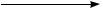
The LX600 in proper orientation for one-star polar alignment
Up until this point we have described the operation of the LX600 in the Alt-Azmuth mode. The LX600 telescope was designed
to be operated in the Polar mode using Meade’s X-Wedge. This precision machined, rigid equatorial wedge is designed to securely mount between the giant fi eld tripod and the LX600 telescope and provides a steady platform ideally suited for long term astro photography.
Instructions to attach the X-Wedge and mount the LX600 telescope can be found in Appendix F: X-Wedge Installation (Page 62-66).
The alignment procedure for an X-Wedge mounted LX600 differs from Alt-Azmuth mode telescope. Meade offers you several polar alignments to choose from, but generally “One-Star Polar Alignment” described below is preferred method.
22
 Loading...