

Page 1
Instruction Manual
LX850™ German Equatorial Mount Telescope System
With StarLock™
Page 2

Page 3
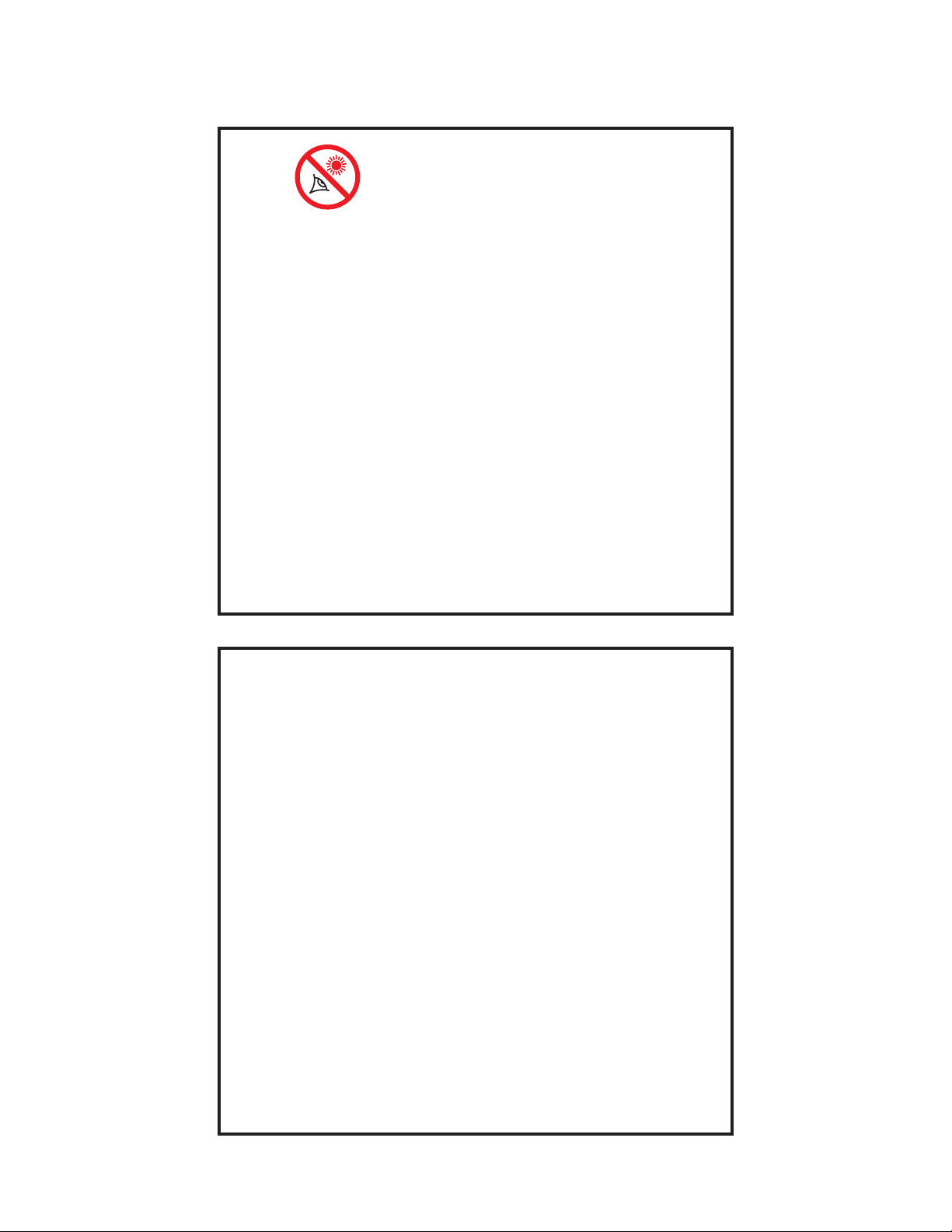
WARNING!
Never use a Meade® LX850
Telescope to look at the Sun!
Looking at or near the Sun will cause
instant and irreversible damage to your
eye. Eye damage is often painless, so there
is no warning to the observer that damage
has occurred until it is too late. Do not point
the telescope at or near the Sun. Do not
look through the telescope or Finder Scope
as it is moving. Children should always
have adult supervision while observing.
Travel Screw:
The LX850 f/8 ACF optical tube assembly (OTA) is
shipped from the factory with the focusing mechanism
protected by a travel screw. This screw secures the
primary mirror in a xed position during travel thereby
protecting the focusing mechanism from shock
damage. This screw is on the back cell of the OTA,
near the Crayford Focuser, and is identied by a dab of
red paint.
This screw must be removed before attempting to focus
the OTA. Failure in removal can result in damage to the
Crayford Focusing mechanism. Retain this screw for
future use as it is suggested that mirror be locked down
anytime the OTA is shipped.
Move the primary mirror to the travel position by rotating
the focuser knob counter clockwise until its travel limit
is reached. Reattach the travel screw and tighten until
rm. Do not over tighten.
Page 4

CONTENTS
Introduction
The LX850 Telescope ........................5
Telescope Features
Precision Machined German Equatorial Mount ....6
Faster, Sharper Optical System ................6
StarLock — Full-Time Automatic Guiding .........6
Key Features
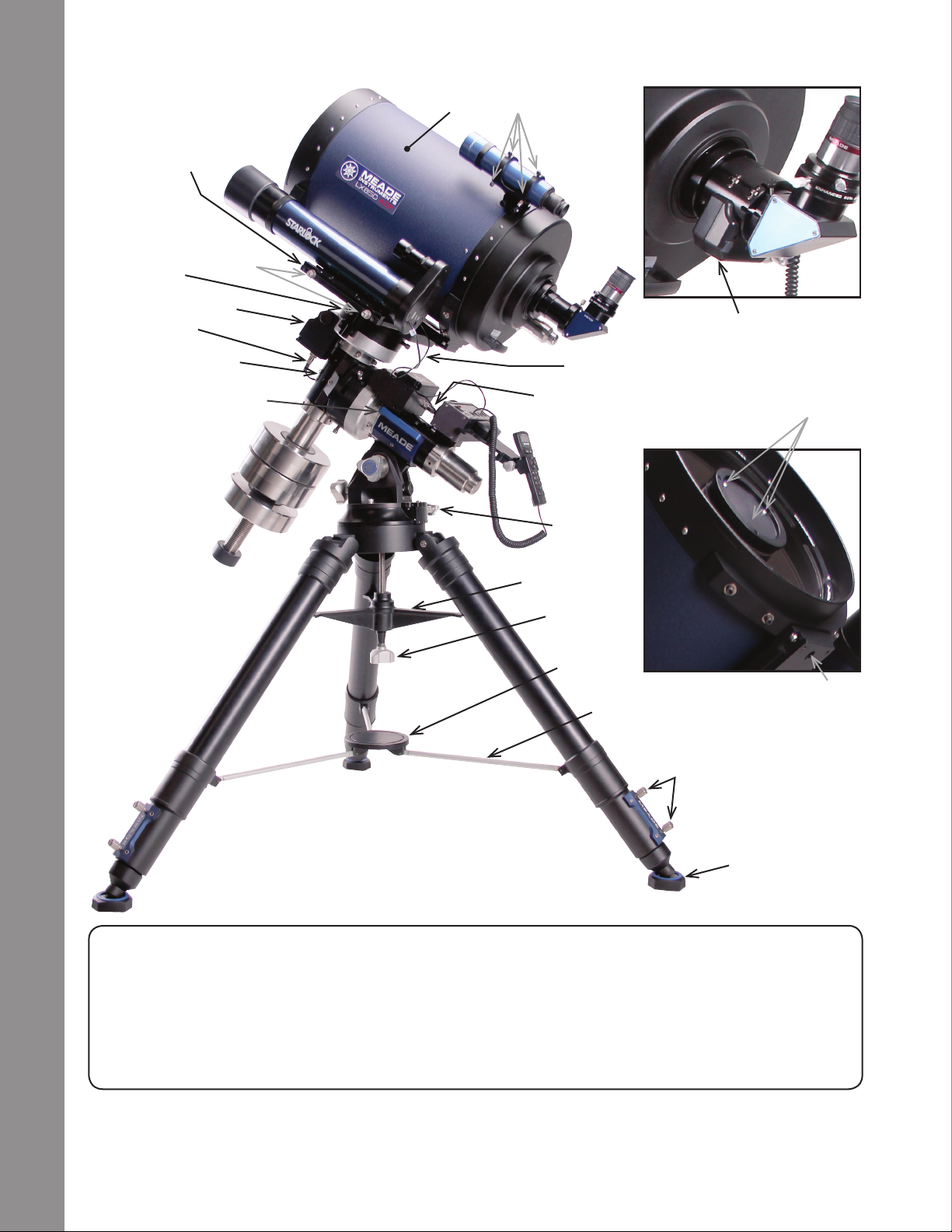
Figure 1: Right View .........................7
Figure 2: Left View ..........................8
Figure 3: Detail RA Access ....................9
Figure 4: Detail StarLock Counterweight .........9
Figure 5: Detail Saddle Plate ..................9
Figure 6a: Telescope Control Panel ............10
Figure 6b: StarLock Control Panel .............10
LX850 Key Features ........................11
Assembly
Assembly Tools ............................13
Tripod Assembly . . . . . . . . . . . . . . . . . . . . . . . . . . . 13
Attach Mount Assembly to Tripod ..............14
Attach Counterweight Shaft ..................15
Attach Counterweights ......................15
Routing Connector Cables ...................15
Removing the Saddle .......................16
StarLock Cable ............................16
Attach the Control Module ...................17
DEC and RA Connecting Cables ..............17
Attach the Optical Tube Assembly (OTA) ........17
Attach Diagonal and Eyepiece ................18
Attach StarLock Assembly ...................18
Plug in the AutoStar II Handbox ...............19
Attach the Viewnder to the OTA ..............19
Mount Additional Accessories and Equipment ....19
Balancing the Telescope .....................19
Balancing the RA Axes ......................20
Balancing the DEC Axes.....................20
Balancing StarLock .........................20
Getting Started
Focusing & Aligning the Viewnder.............21
Focusing the Telescope .....................21
Slew Speeds ..............................22
Aligning for the First Time ....................22
Finding True North/alignment on Polaris.........22
One Star Alignment.........................23
Syncing Your Eyepiece/Camera Using Starlock ...23
Test your Collimation........................24
Collimation of the Optical System: ACF Models ...24
® The name “Meade,” “AutoStar” and the Meade logo are
trademarks registered with the U.S. Patent and Trademark Ofce
and in principal countries throughout the world.
StarLock, Deep Sky Imager”, “LX850”, and “Tonight’s Best” are
trademarks of Meade Instruments Corp.
Protected by U.S. Patent:
US 6,392,799 and other Patents Pending
© 2013 Meade Instruments Corp.
Calibrate Home ............................25
StarLock Operation .........................25
StarLock Automatic Rate Calibration (ARC) ......26
StarLock and Mount Flexure..................26
AutoStar II Operation
The AutoStar II Handbox.....................27
AutoStar Navigation Exercise .................28
Example of Locating a Menu .................28
AutoStar II Menu Tree.......................29
Navigating AutoStar II .......................30
Object Menu ..............................30
Event Menu...............................31
Glossary Menu ............................31
Utilities Menu .............................32
Setup Menu...............................33
“Hot Button” Menu..........................35
StarLock Periodic Error Correction .............36
Advanced Autostar II Features
Adding Observing Sites .....................37
Creating User Objects.......................37
Using AutoStar to Find Objects not in Database...38
To GO TO a user-entered object...............39
Landmarks ...............................39
Identify ..................................40
Browse ..................................41
Alternate Polar Alignments
Two-Star Polar Alignment ....................42
Easy Polar Alignment .......................42
One-Star Polar Alignment ....................42
Align on Home ............................42
How to Drift Align LX850.....................42
Download the Latest Version
of AutoStar II Software....................43
StarLock Assisted PEC Training ...............43
Update Menu Option........................43
Erase Menu Option .........................43
On and Off Menu Options ....................43
Optional Accessories..........................44
Maintenance ................................46
Customer Service.............................46
Specications................................47
Appendix A:
Manual Drift Alignment ......................49
Appendix B:
StarLock Utility ............................50
Appendix C:
Automatic Rate Calibration (ARC) .............53
Appendix D:
Latitude Chart .............................54
Appendix E:
Advanced Coma-Free Optical System ..........55
Appendix F:
Initial Set-up Guide .........................56
Recycling:
How to recycle ................................58
Meade Warranty
One Year Limited Warranty .............. Back Cover
Page 5
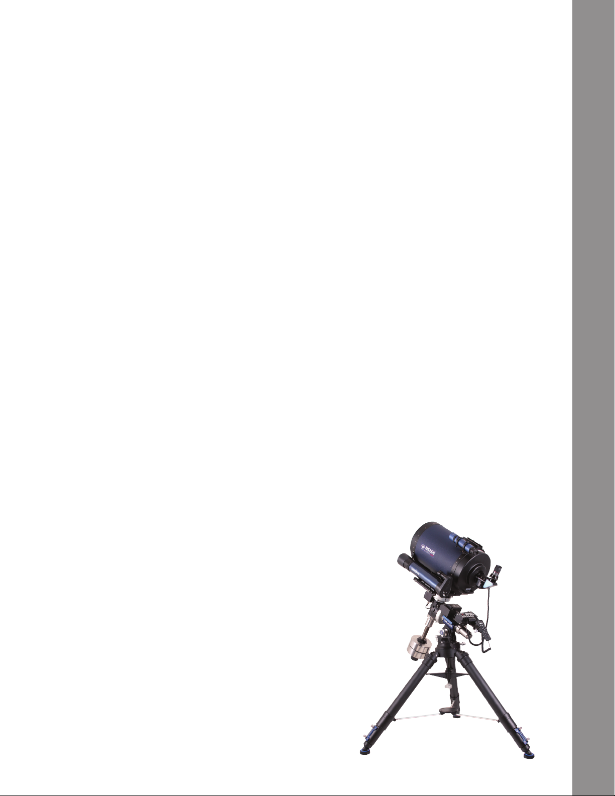
INTRODUCTION
The LX850 Telescope
Advanced Technology for the Astro Imager
Congratulations on receiving your new LX850 telescope. You’ll nd that this telescope system has all you need to
explore the Universe we live in. Designed from the ground up to be the ideal Astro-imaging platform, the LX850
incorporates several new revolutionary technologies that will change the way you observe and image. Available only
from Meade.
Drawing on over 40 years of experience and innovation, Meade Instruments introduces the latest in a long line of
advanced astronomical products: the LX850. Using revolutionary new technology, every aspect of this amazing
telescope system has been designed to deliver the new standard in astrophotographic and visual performance:
• Fast f/8 Advanced Coma-Free (ACF) optical systems on the 10”, 12” and 14” OTAs. These optics
produce wider, atter elds with no coma for pinpoint stars out to the edge of larger imaging sensors
or extreme wide angle eyepieces.
• 130mm 3-element, air-spaced apochromatic f/7 refractor with 3” Crayford-style 10:1 focuser.
Beautifully machined and nished with case. Optional 3” eld attener available.
• StarLock™ full-time automatic integrated guider assists with drift polar alignment, nds and centers
targets and then automatically locks onto a eld star as faint as 11th magnitude for one arcsecond
guiding. No separate computer, no guide star selection, no user focus. Just set up your camera and
image (patent pending).
Introduction
• German Equatorial Mount made from machined aluminum and stainless steel with large bearing
surfaces and roller bearings in both axes for an extremely solid and stable platform.
• Internal Crayford-style primary mirror focusing system with a dual speed 7:1 focus control, on ACF
OTA’s, eliminates image shift and mirror op. Precise focus is a snap (patent pending)
If you are like us, you can’t wait to get outside under a dark sky to use your new LX850 telescope. We have
provided a Getting Started Guide that will get you up and running in the shortest amount of time possible. After
your rst experience, please sit down with this manual and read about all the advanced features that are available
to you with this telescope system. We are condent that the LX850 will keep you fascinated with the Universe and
entertained for many years to come.
Clear Skies,
The people at Meade
5
Page 6

Telescope Features
Meade Instruments introduces the latest in a long line
of advanced astronomical products: the LX850™. Using
revolutionary new technology, every aspect of this
system has been designed to deliver the new standard
in astrophotographic and visual performance.
Precision Machined German
Equatorial Mount
Telescope Features
AutoStar #497 HANDBOX
Constructed of machined stainless steel and aircraft
grade 6061-T6 aluminum, the LX850 mount presents
a rock-solid platform with precision roller bearings on
both axes and a 1.75 inch stainless steel RA shaft. Its
.68 inch diameter brass worms and 5.8 inch diameter,
225-tooth aluminum gears deliver smooth, precise
movement with up to a 90 pound instrument load. Add
to this internal cabling, GPS and the AutoStar II fullycomputerized GoTo system with a database of over
144,000 objects. All this sets atop a new ultra-stable
tripod.
Faster, Sharper Optical System
Building on Meade’s award-winning Advanced ComaFree™ (ACF™) optics, the LX850 employs a fast f/8
optical system with high-contrast bafing that assures
crisp, pinpoint imaging to the very edge of the eld.
The all-new OTAs feature an internal Crayford-style,
zero image-shift focusing system with a two-speed,
7:1 control that rigidly holds the primary mirror (patent
pending). In addition, with the LX850’s optional large-
format, three-element f/5 focal reducer/eld attener,
you gain even wider elds, faster exposures and a
at eld even on larger sensors (available soon). Also
available is Meade's new Series 6000 3 element air-
spaced f/7 apochromatic refractor. This nely machined
and nished OTA features superior optical performance,
a 3" Crayford-style 10:1 focuser and an optional 3" eld
attener.
StarLock™ — Full-Time
Automatic Guiding
StarLock — the heart of the LX850 — is the revolutionary
new technology that makes target acquisition on your
imaging sensor and accurate guiding during exposures
completely automatic. With Meade’s exclusive
LightSwitch™ technology at its core, StarLock uses a
80mm f/5 optic and a super wide-angle lens in a two
camera system that automatically nds your target in
high-precision, immediately captures a eld star as dim
as 11th magnitude and then guides to an incredible
accuracy of one arcsecond. StarLock achieves this
amazing accuracy because, unlike add-on guiders,
StarLock is integrated into the telescope control system
and communicates directly with the motor controllers in
real time with a maximum precision of 0.1 arcseconds.
There’s no need for a separate guider or computer and
StarLock requires no calibration, no user focusing or
guide star selection. StarLock also provides computerassisted polar alignment using the drift method for
extreme precision. No expensive shaft encoders
or add-on guiding systems can provide this level of
performance (patent pending).
6
Page 7
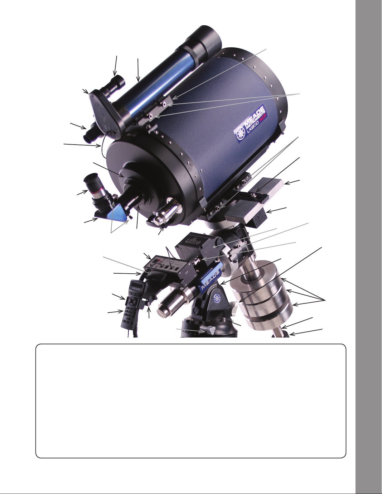
LX850 Key Features
25a
O
24b
O
24a
O
B
28b
O
3!
25b
O
D
G
4a
O
3*
F
1!
J
4b
O
1@
H
20a
O
3)
2@
20b
O
2(
3&
3^
1(
LX850 Key Features
1&
1%
I
1)
Viewnder
B
HD-60 25mm Eyepiece
D
Rear Cell Port
4a
o
SC Thread to 2” ACC Adapter
4b
o
Diagonal Mirror Thumbscrews
F
2” Star Diagonal with 1.25” Adapter
G
2-Speed Focus Knob
H
AutoStar II Handbox
i
Handbox Holder
J
Handbox Holder Tension Knob
1)
AutoStar II Coil Cord
1!
Telescope Control Panel
1@
Counterweight Safety Cap
1#
Counterweight Shaft
1$
Figure 1: LX850 Key Features - Right View
Counterweight
1%
Azimuth Lock Bolts
1^
Altitude Adjustment Knob
1&
RA Clutch Lock Bolts (3)
1(
RA Drive
20a
o
RA Drive Connector
20b
o
DEC Drive
2@
24a
StarLock Narroweld OTA
o
24b
StarLock Wideeld OTA
o
25a
StarLock Imaging Sensor Assembly
O
25b
O
StarLock Mount (On OTA)
28b
O
OTA Dovetail Lock
2(
Altitude Scale
3)
3$
StarLock Cable
1^
StarLock Dovetail Locks
3!
Azimuth Adjustment Knob
3$
StarLock Counterweight
3^
StarLock Counterweight lock
3&
GPS Sensor
3*
1$
1#
7
Page 8
LX850 Key Features
28a
O
3!
2#
2@
LX850 Key Features
2!
3@
4)
AutoStar #497 HANDBOX
2^
C
3#
5@
2#
3%
3$
Viewnder Collimation Screws
C
DEC Drive Power Connector
2!
Optical Tube Assembly (OTA)
2^
Dovetail Plate Safety Bolt
2&
28a
StarLock Mount (on saddle )
O
StarLock Dovetail Lock Bolts
3!
DEC External Cable Access Port
3@
4&
RA External Cable Access Port
3#
Azimuth Adjustment Knob
3$
Collimation Screws (3)
3%
Carry Handles
4)
Leg Locks
4^
Spreader Bar
4&
Tension Knob
4*
4*
4(
5)
4^
5!
Tension Hub
4(
Extension Arms
5)
Anti-Vibration Pads
5!
Zero Image Shift Microfocuser
5@
2&
8
Figure 2: LX850 Key Features - Left View
Page 9
LX850 Key Features
3#
3^
4!
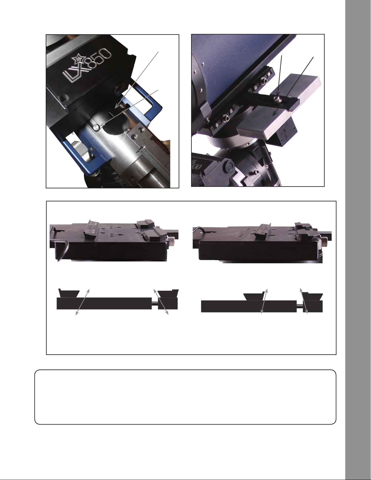
Figure 3: Detail, RA Access Figure 4: StarLock Counterweight
Mount Saddle Plate Congurations
3(
3&
LX850 Key Features
Losmandy® Style Dovetail Conguration Vixen® Style Dovetail Conguration
Note that there are different angled surfaces on the dovetail brackets on the saddle. In addition to physically moving
the dovetail to accommodate the differing width of Losmandy or Vixen it is important to orient the bracket so that the
pitch to the dovetail matches the corresponding mount. Note that Losmandy style mounting conguration utilizes the
larger, more pronounced pitch. See above
Figure 5: Saddle Plate
RA Internal Cable Access Port
3#
StarLock Counterweight
3^
StarLock Counterweight Lock Bolt
3&
Lock-down set screw for cover
4!
9
Page 10

LX850 Key Features
C
A
D
LX850 Key Features
B
E
AutoStar #497 HANDBOX
Figure 6a: Telescope Control Panel
F G H I
4@
4#
10
STARLOCK:
TELESCOPE
CONNECTION
Figure 6b: StarLock Control Panel
Telescope Control Panel:
A. ON/OFF Switch
B. 12v DC Power Connector
C. Electronic Focus Port
D. Illuminated Reticle Eyepiece Power Port
E. 12v DC Output
F. Handbox (HBX) Port
G. RS232 Port
Figure 2-B: LX850 Key Features - Telescope Control Panel
GUIDER
STATUS
RS-232
PORT
4$
Position of Travel
4%
Figure 6c: OTA Rear View
H. StarLock Port
I. Aux Autoguider Port
StarLock Telescope Connection
4@
Guider Status
4#
RS-232 Port
4$
Travel Screw
4%
Screw will vary by
OTA model
Page 11

LX850 Key Features
b Viewnder: 8x50, wide-eld sighting scope with
crosshairs that enables easy centering of objects
in the telescope eyepiece.
c Viewnder Collimation Screws: Adjust these
screws to align the viewnder. See page 23 for
more information.
d Eyepiece: Place the supplied HD-60 25mm
eyepiece into the 2” Star Diagonal with 1.25”
Adapter (Pg 18, Fig. 24) and tighten in place with
locking thumbscrew.
e SC Thread to 2” accessory adapter: The 2”
Diagonal Mirror is inserted into this adapter.
f 2” Adapter Thumbscrews: Tighten to secure the 2”
Diagonal in place.
g 2” Star Diagonal with 1.25” Adapter: Holds the
eyepiece upright for easy viewing. Provides a
more comfortable right-angle viewing position.
Slide the diagonal directly into the 2” Adapter and
tighten the thumbscrew to a rm feel only. See
page 18 for a photo and more information.
D. Illuminated Reticle Port
E. 12v DC Output
F. Handbox (HBX) Port
G. RS232 Port
H. StarLock Port
I. Aux Autoguider Port
1# Counterweight Safety Cap: Prevents the
counterweight from accidentally slipping off the
end of the counterweight shaft.
1$ Counterweight Shaft: Thread the counterweight
onto this shaft (below).
1% Counterweight: Counterbalances the weight of the
optical tube, and adds stability to the mount.
1^ Azimuth Lock Bolts. Once your LX850 is aligned
on the celestial pole, lock the azimuth bolts to
prevent movement in this direction.
Latitude Adjustment Knob. Used to set the LX850
1&
to the correct Latitude for your observing site.
LX850 Key Features
h 2-Speed Crayford Style Focusing Knobs: Moves
the telescope’s primary mirror in a nely-controlled
motion to achieve precise image focus. The
LX850 telescopes can be focused on objects from
a distance of about 200 ft to innity. Rotate the
focus knob clockwise to focus on distant object.
i AutoStar II Handbox: The LX850 user interface.
Use the Handbox to command the LX850 to
automatically slew to any object in the night sky.
See pages 27 thru 36 for a description of features.
j Handbox Holder: convenient place to place your
AutoStar II box. Keeps it at the ready.
1) Handbox Holder Tension Knob: Loosen to adjust
presentation angle – tighten to lock in place.
1! AutoStar II Coil Cord: Connects the handbox to
the Computer Control Panel via the HBX port.
1@ Telescope Control Panel:
A. ON/OFF Switch
B. 12v DC Power Connector
C. Electronic Focus Port
Latitude Lock Knob. Before using the Latitude
1*
Adjustment Knob, loosen the Latitude Lock
Knob. Once the Latitude is adjusted, be sure to
lock this knob to prevent unwanted movement of
the LX850.
RA Clutch: Tighten the three hex head screws
1(
using the included 5/16” hex head tool to engage
the RA Drive.
a. RA Drive: Precisely moves the telescope around
2)
the RA Axis.
b. RA Drive Cable: Connect the RA drive to the
2)
Telescope Control Panel.
DEC Drive Cable: Connects the DEC Motor to the
2!
Compute Control Panel.
DEC Drive Housing: Precisely moves the
2@
telescope around the DEC Axis.
DEC Clutch: Tighten the three hex head bolts
2#
using the included 5/16” hex head tool to engage
the DEC Drive.
a StarLock Narrow Field OTA: Narrow eld
2$
optics that are used to precisely guide LX850
11
Page 12

LX850 Key Features
StarLock System.
b StarLock Wideeld OTA: Used to orient the
2$
LX850 in relation to the sky.
a StarLock Connector Panel: Starlock cable
2%
connection point and place where Starlock status
is displayed.
b StarLock Connector Cable: 4-pin connector cable
2%
plugs into StarLock.
Optical Tube Assembly (OTA): The main optical
2^
component that gathers the light from distant
LX850 Key Features
AutoStar #497 HANDBOX
objects and brings this light to a focus for
examination with the eyepiece.
Dovetail Rail Safety Bolt: Make sure the Safety
2&
knob is securely attached.
StarLock Mount (Left side view): Attaches
2*
StarLock to the telescope mount saddleplate.
OTA Lock: Secures the OTA to the LX850 saddle
2(
plate.
this weight. Remove if you mount StarLock directly
on the OTA.
StarLock Counterweight Lock: Tighten to secure
3&
the counterweight in place.
GPS Sensor: Used to get precise date, time
3*
and location of your observing site using global
positioning satellites.
Dovetail Adapter Attachment Rails: The LX850
3(
dovetail adapter is unique in that it will accept both
the Losmandy and Vixen style dovetails. Remove
and reverse the two surrounding dovetail rails so
the correct rail angle points toward the dovetail
size being used. Be sure to securely tighten the
rails. See page 9.
LX850 Carry Handles: Use these carry handles
4)
to help move the LX850 mount from one location
to another.
Access Port Knob: Secures cover plates to RA
4!
and DEC cable raceway.
Altitude Scale: Set the latitude of the
3)
observing site on this scale using the latitude
adjustment knob.
StarLock Locking Bolt: Secures the StarLock
3!
assembly to the saddle plate.
DEC Internal Cable Access Port: Loosen the two
3@
thumbscrews, slide the door open to gain access
to the cable raceway that runs the length of the
DEC Axis.
RA Internal Cable Access Port: Loosen the two
3#
thumbscrews, slide the door open to gain access
to the cable raceway that runs the length of the RA
Axis.
Azimuth Adjustment Knob: Once the Azimuth
3$
Locking bolts are loose, make adjustments to the
mounts azimuth position aligning it to the celestial
pole. When properly adjusted, lock the Azimuth
Adjustment Lock bolts to prevent unwanted
Azimuth movement in the LX850.
ACF Collimation Adjustment Screws: Use these 3
3%
screws to ne tune your OTA’s optical alignment.
StarLock Telescope Connection: Connect
4@
StarLock to the telescope control panel.
Guider Status: LED indicates operation.
4#
RS-232 Port: Additional RS-232 port.
4$
Travel Screw: Firmly secures the primary mirror
4%
in a xed position during travel protecting the
focusing mechanism from shock damage.
Remove this screw before attempting to focus the
telescope.
Leg Lock: Locks leg extension in place.
4^
Spreader Bar: Rigidly holds legs open.
4&
Tension Knob: Tightens spreader bar to legs.
4*
Tension Hub: Locates extension arms.
4(
Extension arms: Locates tripod legs.
5)
Anti-Vibration Pad: reduces vibrations and
5!
shortens damp-down time.
Zero Image Shift Microfocuser for precision,
5@
remote focusing.
12
StarLock Counterweight: Precisely counter
3^
balance the StarLock assembly by moving
Page 13
Assembly
You may want to perform the assembly of the LX850
in the light of day to become familiar with the parts and
operation before performing observations on the night
sky. Setup the telescope in a large open area where
you can see lots of sky. Do not setup right next to a
building or a wall that will obstruct its view of the sky.
Make sure the ground is stable and is approximately
level. It is best to set up the scope away from bright
nighttime lighting, as bright lights will spoil your night
vision and impede your ability to see the sky.
The LX850 system includes the following:
• German Equatorial Mount Assembly with Dovetail
Saddle Plate
• StarLock Optical Tube and Sensor Assembly
• Counterweight(s)
• Counterweight Shaft with Safety Nut
• LX850 Field Tripod
• LX850 Accessories
• LX850 Control Panel
• Autostar II Hand Controller
• StarLock Cable
• StarLock Counterweight
• Custom Utility Tool
• 5/16” Hex head wrench
• DVD with AutoStar Suite and software
• #507 Connecting Cable with USB Adapter
• Internal Cable Fish Tool
• Anti-Vibration Pads
• Micro-focuser (ACF OTAs only)
Additionally, the LX850 can be ordered with various
OTAs and Accessories and may contain additional
counterweights and boxes depending on the
conguration ordered.
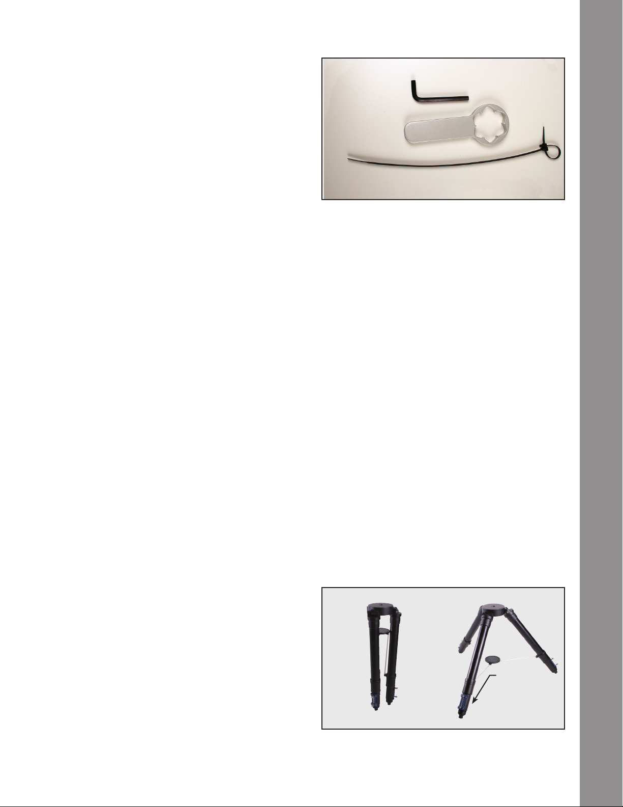
5/16" Hex Head Wrench
LX850 Utility Tool
Assembly
Internal Cable Fish Tool
Fig 7: LX850 assembly tools.
• Internal Cable Fish Tool: Assist routing StarLock,
DEC,RA and accessory connecting cables
Use of these tools will be described in the assembly
procedure. If you will be attaching an OTA that utilizes
a Vixen Style dovetail you will need a 3/16” hex head
wrench (included) to relocate the mounting rails on the
dovetail plate.
Tripod Assembly
Remove the LX850 eld tripod from the shipping
carton. Included in this carton is the spreader bar,
threaded rod (with spacer) and retaining clip; set these
aside. Position the tripod where you want the telescope
to be assembled. Stand the tripod vertically with the
tripod feet down and with the tripod still fully collapsed.
Grasp two of the tripod legs and, with the full weight
of the tripod on the third leg, gently pull the legs apart
to a fully open position. The legs should be spread so
the three leg braces are spaced evenly apart and the
tripod head is approximately level. Position one of the
legs so that it points approximately true South (True
North in the southern hemisphere). This will allow the
counterweight shaft to clear the tripod if used at low
latitudes.
Assembly Tools
All of the tools necessary to assemble your LX850
telescope will be found in the accessory box:
• LX850 lock knob wrench: A dedicated tool for
securing small and large knobs on both the
telescope and tripod.
• 5/16” hex head wrench: Required for securing
DEC and RA clutches.
Leg points to
true South
Collapsed Opened
Fig 8: Tripod.
13
Page 14
Loosen the two (2) leg lock-knobs on each tripod leg.
Adjust the height of the tripod to the desired height
and with the tripod head approximately level, tighten
the leg locks. Tighten the locks to a rm feel only; do
not over tighten.
Assembly
Slide the threaded rod through the spreader and then
slide this assembly through the central mounting hole
in the tripod head. Place the threaded rod through
central mounting hole far enough so that the retaining
clip channel is exposed. Press t the retaining clip
through the machined channel. The retaining clip will
now hold the spreader bar for easy assembly.
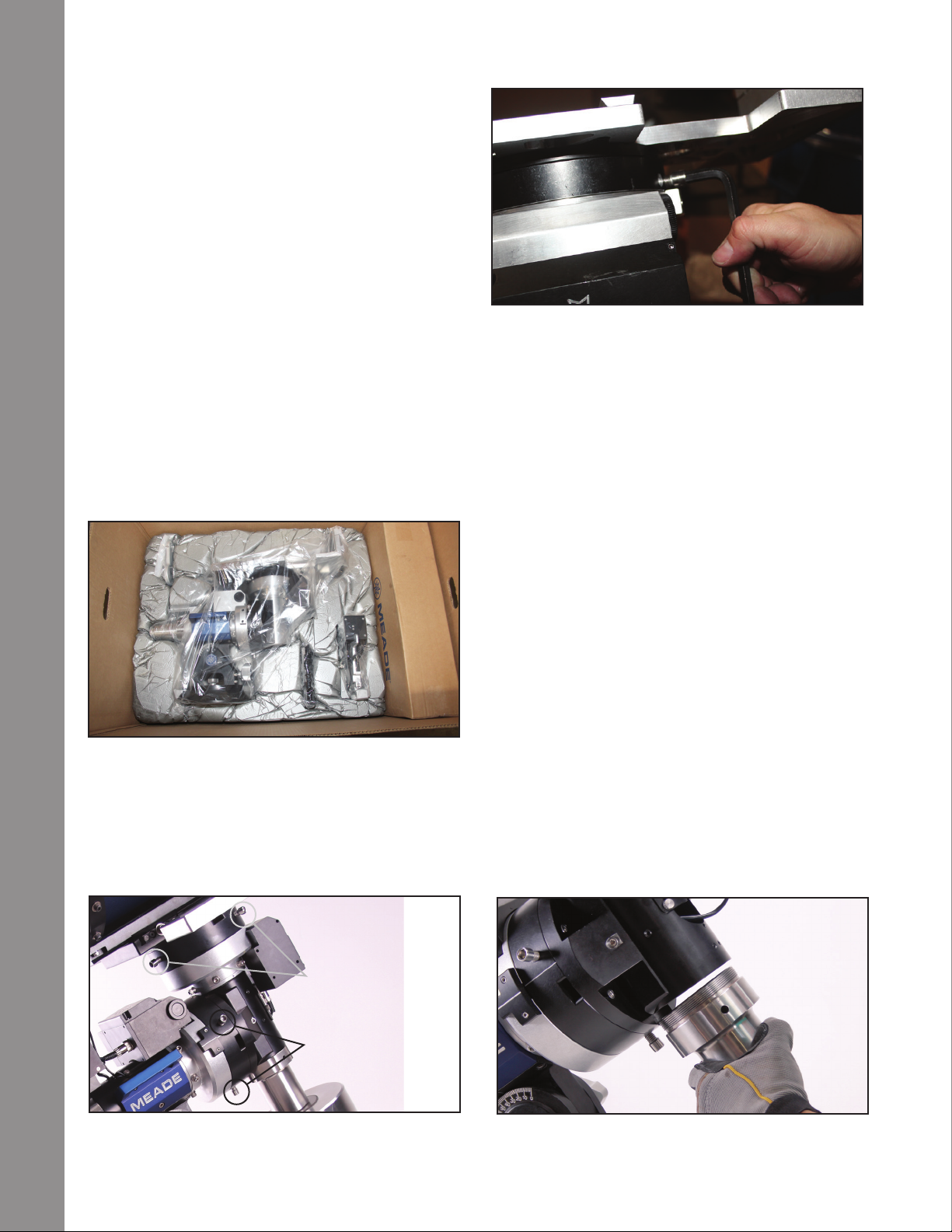
Attach Mount Assembly to Tripod
Remove the equatorial mount assembly from the
AutoStar #497 HANDBOX
shipping carton. You may notice as you are removing
the mount that the RA and DEC clutches are not
locked. This is intentionally done at the factory to
prevent possible damage to the gears while in transit.
Fig 9: Mount in Box
Fig 11: Tighten Clutch.
assembly. DO NOT OVERTIGHTEN.
Place the mount on the tripod head. At this point it is
advisable to either use one hand, or (ideally) enlist
someone else’s hand, to steady the mount while it is
fastened to the tripod.
Orient the mount so that it aligns with the poles, control
panel facing the South pole (North pole in the southern
hemisphere). Push the threaded rod up and secure
the mount to the tripod by tightening the central lock
knob. Use the supplied custom utility tool to secure it
to a “tight” t. If properly secured, the spreader bar will
make contact with all three tripod legs and the mount
will not slip.
Setting Latitude
Refer to the latitude chart on Appendix D, page 54.
Listed are the latitude for most major cites world wide.
Locate your city in the chart and note its latitude. If
your city is not listed follow the formula to calculate
your locations latitude.
14
Manually tighten down the three (3) RA and three
(3) DEC clutch lock bolts using the supplied 5/16”
hex head wrench to facilitate easier handling during
DEC Clutch: Two of three
shown, third on opposite
side (not visible).
RA Clutch: Two of three
shown, third on opposite
side (not visible).
Fig 10: DEC and RA Clutch Locations
Loosen the Attitude Adjustment Lock Knob (g. 18,
page 7). Locate the Attitude Adjustment Knob (g. 17,
page 7) and the Latitude Scale (g. 30, page 8). The
Fig 12: Attach Counterweight Shaft.
Page 15
latitude scale has markings and a range that start at
zero (0) and ends at 70. Turn the Attitude Adjustment
Knob until the indicator points to your corresponding
latitude. Tighten the Attitude Adjustment Lock Knob.
THE POSITION OF YOUR HANDS SO NOT TO
PINCH THEM DURING ADJUSTMENT.
Screw the safety nut on then end of the shaft after the
counterweight(s) have been attached.
Attach the Counterweight Shaft
Remove the counterweight shaft, with attached safety
nut, from its packaging. The safety nut is attached at
the factory for shipping. Removing the safety nut at
this time to lighten the counterweight shaft and make it
easier to attach on the DEC axis. Remove the retaining
nut by unscrewing it and set aside. Thread the shaft
into the receiver, making sure that the threads are
matching, not binding or cross threading.
Attach the Counterweight(s)
The counterweights are attached by threading them
onto the counterweight shaft to the desired position. If
the LX850 mount was purchased with a Meade optical
tube assembly (OTA), additional counterweights may
have been included depending on the OTA purchased.
Attach all counterweights that were included with the
mount. A good starting position for the counterweights is
to place them in the middle portion of the counterweight
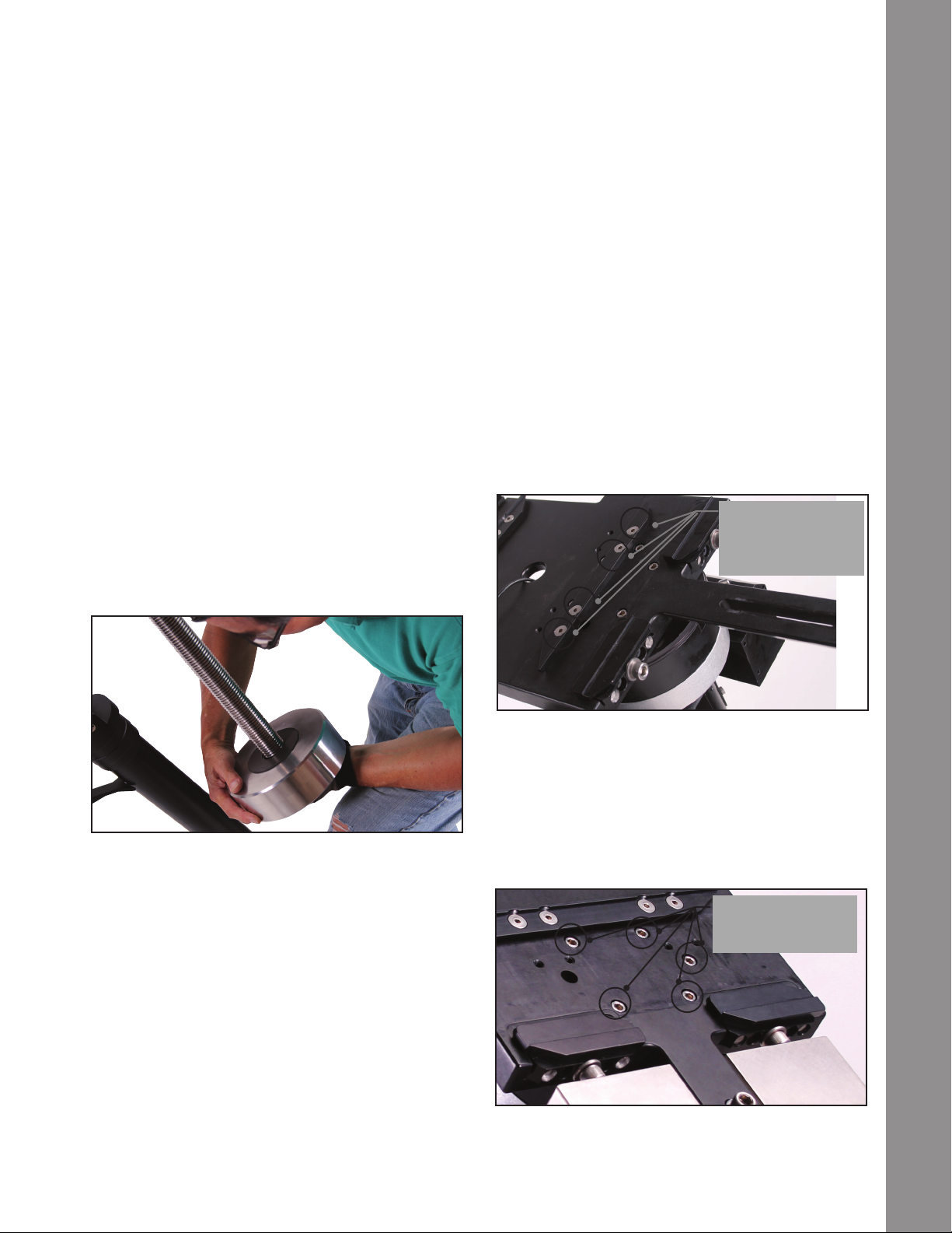
Routing Connector Cables Internally
Designed into the LX850 mount is a raceway that
routes cables through the body of the mount. Cables
connecting the RA, DEC motors and StarLock to the
control panel can be routed through this raceway,
eliminating worrisome “cable interference.” The
dedicated connecting cable(s) can be found in the
StarLock and/or the accessories box along with a
assisting cable routing tool. Cables for additional
equipment such as cameras can also be routed
through the internal raceway. Note: the StarLock
cable has been installed at the factory. Starlock’s 6-pin
Remove these four
fasteners to gain
access to dovetail
saddle plate fasteners.
Assembly
Fig 13: Attach Counterweight.
shaft. When the mount is fully assembled with OTA
and accessories, the counterweights will be adjusted
to obtain a proper balance with the OTA. Note: 12”
and 14” f/8 ACF models please refer to Appendix F for
detailed counterweight instructions.
NOTE: WHEN ATTACHING THE COUNTERWEIGHT(S) TAKE CARE NOT TO DROP THEM
DURING ASSEMBLY AS THEY CAN CAUSE
SERIOUS INJURY, ESPECIALLY ON THE FOOT.
WHEN ATTACHING OR ADJUSTING THE POSITION
OF TWO (2) Counterweights PAY ATTENTION TO
Fig 14: Remove left OTA dove tail mount.
connector connects to the control panel and the 4-pin
connector should be threaded through the hole in the
saddle plate and connected to the StarLock.
Remove these
fasteners to remove
dovetail saddle plate.
Fig 15: Access to left saddle fastener revealed.
15
Page 16
Removing the Saddle
Your telescope mount shipped from the factory with the
OTA mount saddle attached. You will have to remove
it to gain access to the upper portion of the internal
raceway to nish routing any additional cables you
want to run to the OTA for cameras of other optional
Assembly
equipment. Remove the StarLock counterweight by
loosening its retaining knob and sliding it off. Using a
3/16” hex-head wrench, loosen and remove the ve
(5) hex nuts that fastens the saddle to the mount Take
care when removing the fth (5th) and last fastener;
making sure to support the weight of the saddle as it
becomes free.
With the saddle removed, you are now ready to
route the cable(s) through the upper portion of the
AutoStar #497 HANDBOX
internal raceway. The StarLock cable comes prerouted from the factory. If it has been removed or you
need to route additional cables from the OTA (eg.
Camera cables) follow these instructions.
so that it will plug into its corresponding receptacle.
The four-pin connector is inserted into the four-pin
receptacle on the back of the StarLock. The six-pin
connector is plugged into the six-pin receptacle on the
mount control panel labeled “StarLock”. Please note
the correct cable orientation before beginning to route
the cable(s).
Fig 19: Route of cable from StarLock module
StarLock Cable:
Direction of Cable
Fig 17: Routing cable under the saddle plate.
Important note: the StarLock cable is directional! Each
end has connectors with different congurations; each
connector conguration must be correctly oriented
Fig 18: Pulling cable out to connect to control panel.
Begin by passing the four-pin connector thru the side
passway in the DEC housing below the OTA saddle
(Page 8 and 9, g 2 and 3). This four-pin connector
will plug-in to the receptacle on the back of StarLock.
Pass the cable end with the six-pins down the DEC
shaft. Open the access port at the front of the RA axis
Fig 16: Access to the cable raceway.
and as the six (6) end feeds down grasp and pull it out,
taking care not to pull the four-pin connector through
the side passway in the DEC housing. Then feed the
six-pin end down the RA shaft toward the DEC access
door (Page 8, Fig 32). Slide open the cable access
port door by loosing the two knurled knobs (Page 9,
Fig 41). Observing through this port, and feeding the
six-pin cable through, grasp it as it comes through
the port. Again, take up the excess cable. This six-pin
16
Page 17
connector is now ready to be inserted into the RS232
receptacle on the control panel labeled “StarLock.”
At this point you will need to reattach the Optical Tube
Saddle Plate. Reverse the steps outlined in the step
“Removing the Saddle” above.
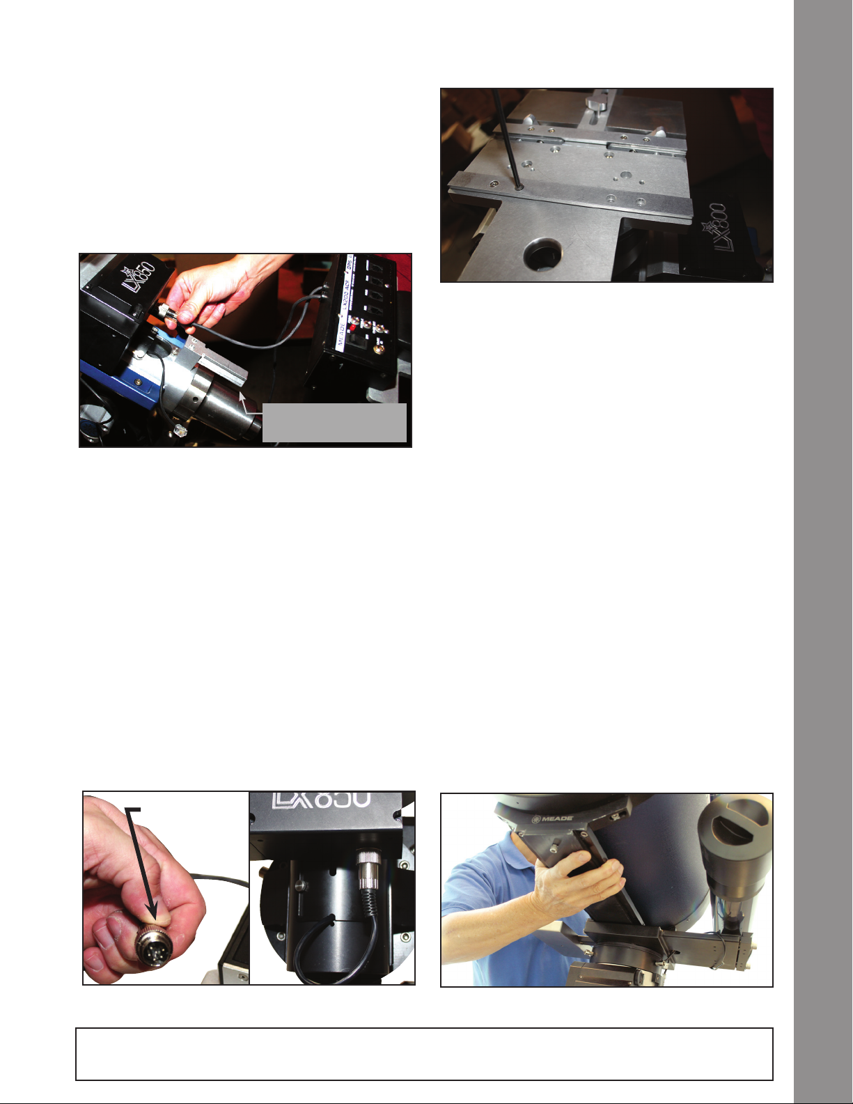
Attach the Control Module
Take the control panel module out of the box that
Note Rail to attach
Telescope Control Module
Fig 20: Connecting motor to control module.
contained the mount, and slide it on the mounting
rail at the rear end of the RA housing. Loosen the
two knurled set-screw knobs on the bottom side of
the control module and slide it on the rail, tightening
the same set-screw knobs. Insert the StarLock six-
pin connector into the receptacle labeled “StarLock”
(Page 10, Fig. 6a, H).
DEC and RA Connecting Cables
The connecting cables for the RA & DEC are attached
to the control panel module and can not be removed
from the module. The short cable connects directly
to the RA gearbox that is directly above the module.
Assembly
Fig 22: Replace the saddle plate
Insert the DIN connector, observing and aligning the
orientation of the pins to match. Once the pins are
seated, secure by screwing the dedicated retaining
collar until rm (Fig. 21). The longer cable connects
to the DEC gearbox and will need to be threaded
through the access port on the RA axis, directly above
the module (Fig. 20). Using the cable pull tool feed
the cable through the raceway, watch for it through
the access port on the front of the RA axis (Fig. 21).
Grasp it as it comes within reach, and feed through the
excess cable. Once it has been fed through, insert and
secure the connector to the DEC drive directly above
the access port (Page 8, #21). Once the pins are
seated, secure by screwing the dedicated retaining
collar until rm.
Attach the Optical Tube
Assembly (OTA)
Note that there are two options for orientating the
dovetail rail and its location. As shipped from the
factory, dovetail rails are congured to receive a
standard Losmandy®-style dovetail. Meade LX850
OTAs are shipped with their dedicated dovetail plates
pre-attached to the tube. Depending on your OTA’s
Note: Locking
collar
Fig 21: DIN Style Connector
NOTE: Remove the travel screw before attempting to focus the OTA. Failure to do so may result in damage
to the Crayford focusing mechanism.
Fig 23: Slide the OTA dovetail into the saddle plate
17
Page 18
dovetail, you may need to relocate both sides of the
dovetail receiver rails (Page 9, Fig. 5).
• OTAs with a Losmandy®-Style Dovetail: All
Meade LX850, Advanced Coma-Free Optical
tubes utilize the standard Losmandy®-style
Assembly
AutoStar #497 HANDBOX
dovetail plate. To prepare the LX850 Dovetail
adapter to accept the Losmandy dovetail plate,
the mounting rails on the dovetail adapter must
be positioned in the correct location and with the
correct long side of the rail facing inward toward
its corresponding mounting rail. If you look at each
long side of the rail, you will notice the draft angle is
different on each side (Page 9, Fig 5). Make sure
the correct angled side is used on both rails before
attaching the OTA. Both rails should be secured
rmly to the dovetail adapter before an OTA
is attached.
• NOTE: Due to its weight and size, it is advisable
that the 12” & 14” Advanced Coma-Free OTAs be
mounted by two (2) people.
• OTAs with a Vixen®-style dovetail: All Meade
LX850 refractors utilize a standard Vixen®-style
dovetail plate. To congure the dovetail adapter to
accept this dovetail plate, orient the adapter rails
so that the narrow draft angle is facing inward
as shown (Page 9, Fig. 5). Position the inner
rail so that it will mate with the narrowest set of
mounting points.
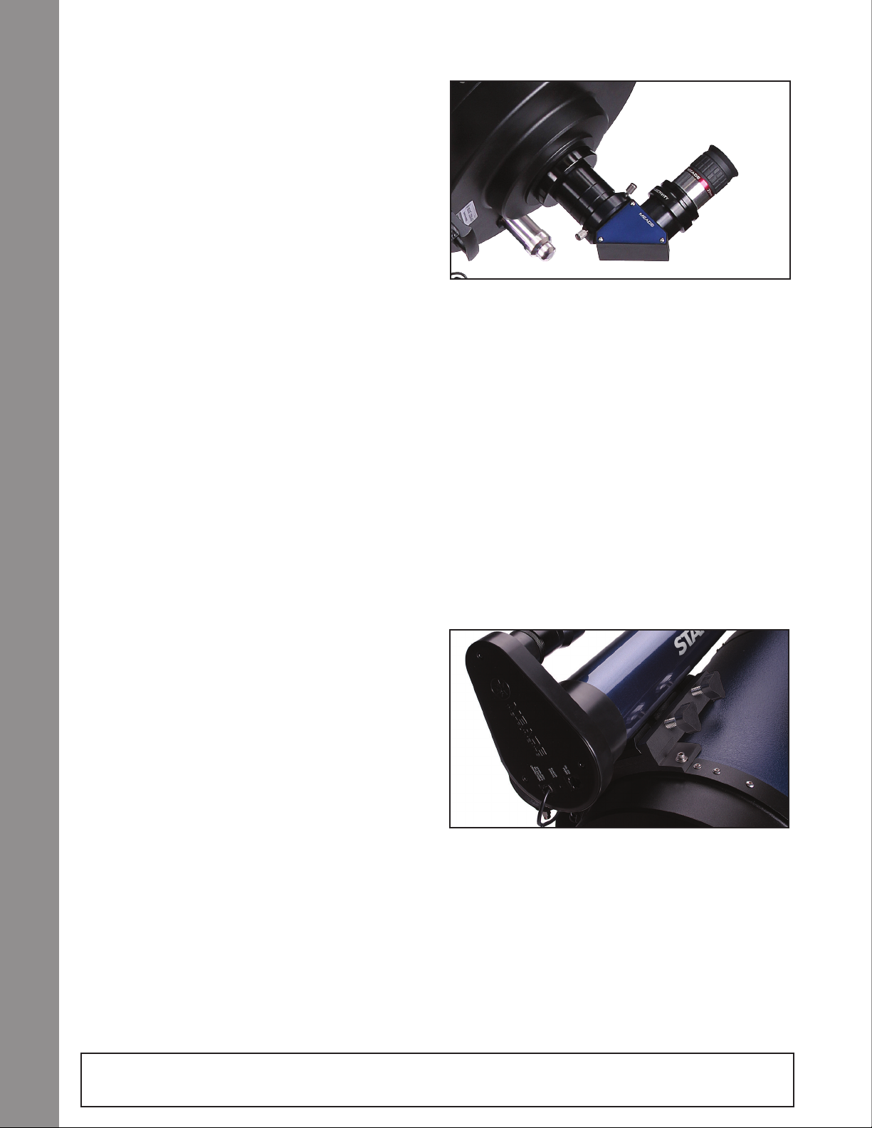
Fig 24: Diagonal and eyepiece in place
detailed instructions that were included.
• Meade Refractors: Slide the diagonal mirror
into the focuser and lock in place by turning the
thumbscrew(s) to a rm feel. Remove the Meade
eyepiece from its container and place it in the
diagonal mirror. Tighten the thumbscrew(s) to a
rm feel only.
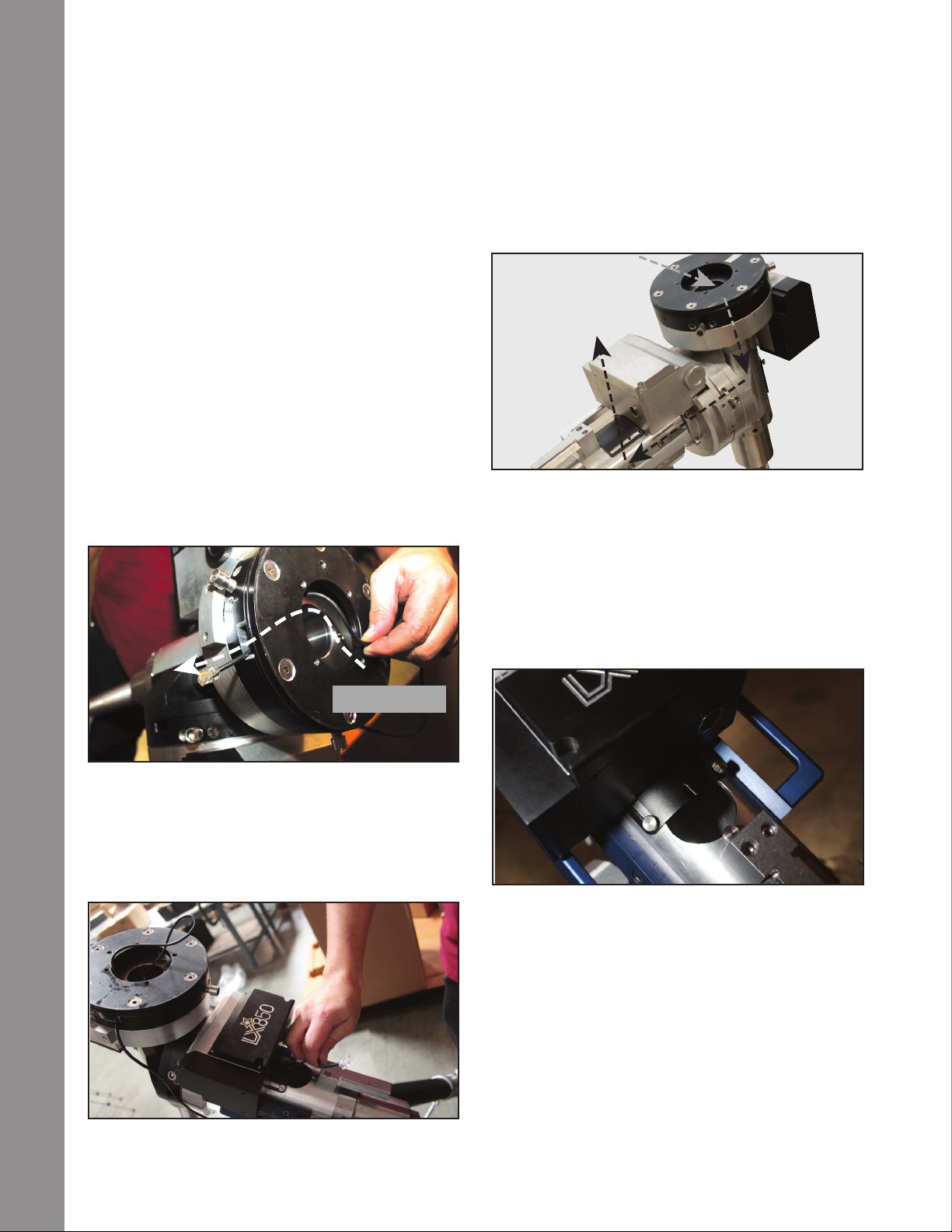
Attach StarLock Assembly
StarLock’s default mounting location is on the saddle
plate. The 10”, 12” and 14” ACF models feature a
second mounting location at the top-rear of the optical
tube assembly. Due to the longer focal length of the
ACF optics, this second, top of the OTA mounting
point, is preferred for these telescopes, as it minimizes
18
NOTE: Before attaching an OTA to the mount, make
sure the clutches on each axis are locked so the mount
does not shift during OTA installation and the proper
number of counterweights are attached.
The saddle plate is pointing straight up the RA axis
with StarLock dovetail mounting position on the left
side when viewed from behind the mount.
To attach an OTA, rmly grasp the OTA, remove from
the shipping box, and slide the dovetail plate into the
dovetail adapter. Maintaining a rm grip on the OTA,
tighten the two (2) lock-bolts on the dovetail adapter
to a “rm” feel.
Attach Diagonal and Eyepiece
Remove the dust cap from the rear cell of
the telescope.
• Meade Advanced Coma-Free OTAs: If your
telescope was shipped with Meade's #1209 Zero
Image Shift Microfocuser please refer to the
NOTE: Remove the travel screw before attempting to focus the OTA. Failure to do so may result in damage
to the Crayford focusing mechanism.
Fig 25: StarLock mounted on ACF OTA
any differential exure.
Locate and unpack the StarLock assembly. The
dovetail adapter and its dedicated counterweight are
pre-installed at the factory and are correctly congured
for use in the Northern Hemisphere. For use in the
Northern Hemisphere, the StarLock assembly is
attached to the dovetail adapter on the left side of the
Page 19

Fig 26: Mounting StarLock to the saddle plate. Attach
StarLock counterweight.
OTA. To install StarLock, loosen the two (2) retaining
nuts at the side of dovetail adapter, slip in the StarLock
assembly, position Starlock so that the back edge of
the StarLock dovetail is ush with the lower edge of
the saddle plate. Tighten to securely retain StarLock
(Page 8, Fig. 42). Locate the included rectangular
counterweight, loosen its securing thumbscrew, and
slide it on the rail on the opposite side of the dovetail
adapter (if needed). Note that the counterweight is
NOT needed when StarLock is mounted to a LX850
ACF OTA. Use the counterweight when StarLock
is mounted directly to the saddle plate. Secure the
counterweight by re-tightening the nuts.
Attach the Viewnder to the OTA
The Meade OTAs sold with the LX850 are equipped
with a standard 8x50 nderscope. To assemble and
align the viewnder, perform steps 1 through 6 below
during the daytime.
1. Assemble the viewnder by attaching all included
thumbscrews onto the viewnder bracket and
Fig 28: Slide viewnder into receiver
insert the 8X50 viewnder into the bracket. Tighten
the thumbscrews to a rm feel only so the 8x50
optical tube is roughly centered in the middle of
the bracket.
2 . Slide the viewnder bracket into its mounting
assembly on the OTA (Page 7, Fig. 1, #1). To secure
the viewnder to the mounting assembly, tighten
the two thumbscrews (Page 7, Fig. 1, #2) to a rm
feel only.
Assembly
Fig 27: Connect handbox cable to HBX
Attach the four-pin StarLock connector cable to the
rear panel of StarLock in the receptacle on the left side
(Page 10, Fig. 42).
Plug in the AutoStar II Handbox
Locate and unpack the AutoStar II handbox. The
connecting cable is packed together with the handbox.
Plug one connector into the handbox, and the other
into the “HBX” receptacle on the control module.
Mount Additional Accessories and
Equipment
At this time it is advisable to mount any additional
accessories and equipment that you will be using
during nighttime use. Balancing the telescope is the
next step and it is important that this procedure be
performed in its operational conguration.
Balancing the Telescope
Level the mount, using the integrated bubble level
at the base of the mount as an aide if necessary, by
adjusting the length of the three tripod legs.
Before using the telescope, you will need to balance the
RA/DEC axes and the StarLock. Before you balance,
attach the eyepiece assembly, the viewnder and all
the accessories you will be using with the telescope
(cameras, guide scopes, etc.). In other words, you
need to balance the unit with all the “weight” that will
be attached to it.
19
Page 20

To balance the telescope, unlock the Right Ascension
or RA clutches (3-Places, Page 14, Fig. 10). When
this axis is unlocked, the telescope pivots on the RA
axis. Later in the procedure, you will also unlock the
Declination or DEC clutches (3-Places, Page 14, Fig.
Assembly
10). When unlocked, it pivots on the DEC axis. Try to
Assembly
become familiar with these locks and observe how
the telescope moves on each axis. To obtain a ne
balance of the telescope, follow the method below:
Balancing the RA Axis
1. Firmly hold the optical tube secure so that it cannot
accidentally swing freely. NOTE: An unbalanced
OTA can swing quickly causing injury to the user.
Loosen the RA Clutch. The optical tube now moves
freely about the RA axis. Rotate the telescope so
that the counterweight shaft (Page 20, Fig. 29) is
parallel (horizontal) to the ground.
Slide the OTA to
achieve balance
Fig 30: Balancing the DEC axes
dovetail mount. Be careful that the OTA does not fall
out of the dovetail adapter! Start with 1/2" of the OTA
dovetail plate extended out of the DEC Saddle (See
Appendix F, pg 56). Move the OTA assembly fore or
aft, in the dovetail adapter until the telescope remains
in horizontal position without tending to drift down in
either direction. Once this is achieved tighten the OTA
dovetail lock knobs rmly.
RA Axis
Move Counterweight
To Achieve RA Balance
Fig 29: Balancing the RA axes
2. Rotate the counterweight along the counterweight
shaft until the telescope remains in the horizontal
position without moving in either direction. Now
push the RA shaft from the end up and down.
Adjust the counterweight position until it takes the
same force to move the RA shaft up and down.
Balancing the DEC Axis
Again, hold the optical tube so that it cannot accidentally
swing freely. NOTE: An unbalanced OTA can swing
quickly causing injury to the user. Position the RA axis
parallel to the ground and tighten the RA locks. Unlock
the DEC Clutches. The telescope now is able to move
freely about the DEC axes. Position the OTA parallel
to the ground.
Advanced Coma-Free OTAs: Slightly loosen the OTA
dovetail adapter lock knobs (Page 8, Fig. 29) so that
the tube assembly slides easily back and forth in the
Meade Refractors: Slightly loosen the cradle ring lock
knobs so that the main tube slides easily back and
forth in the cradle rings. Move the main tube in the
cradle rings until the telescope remains in one position
without tending to drift down in either direction. Once
this is achieved tighten the cradle ring lock knobs. If
the refractor is equipped with a dew shield, make sure
it is fully extended prior to balancing.
Balancing the StarLock
When the StarLock is mounted on the saddleplate
it is mounted off-center from the DEC axis, it must
be properly counter-balanced to achieve optimum
performance. With the DEC axis lock still loose and with
the RA axis parallel to the ground, rotate the OTA so
that points directly upward (Fig. 31). Start by loosening
and moving the rectangular StarLock counterweight
so there is a 1/2" gap between the weight and the DEC
Saddle plate screws (See Appendix F). Move the
weight until the telescope remains pointing upward,
without tending drift in either direction. Once this is
achieved tighten the StarLock counterweight knob and
re-lock the DEC clutches.
The telescope is now properly balanced. Return the
LX850 to the original position with the counterweight
shaft pointed to the ground and OTA pointed
straight ahead.
20
Page 21

Fine Focus Knob
Fig 31: Balancing the StarLock assembly
Getting Started
Focusing and Aligning the Viewnder
1 . If you have not already done so, insert the Meade
eyepiece into the diagonal mirror on the rear of
the OTA.
2 . With the telescope properly balanced in both axes
(See the section “ BALANCING THE TELESCOPE”
BEFORE performing this step), Unlock the RA
and DEC clutches (Page 14, Fig. 10) so that the
telescope moves freely on both axes.
3. Point the telescope at some well-dened and
stationary land object at least 200 yards distant,
such as the top of a telephone pole or street sign.
Center the object in the telescope eyepiece (See
Focusing the Telescope section below). Re-tighten
the RA and DEC clutches.
Coarse Focus Knob
Fig 32: Dual speed Crayford focuser
Focusing the Telescope
Meade Advance Coma-Free (ACF):
Note: All LX850 ACF optical tube assemblies ship
from our factory with a Travel Screw. This screw MUST
be removed before focusing the telescopes optics. For
details see pages 3 and 10, g. 6b.
These optical tubes are equipped with an internal
Crayford-style, zero image shift primary mirror focuser
with dual speeds (7:1 ratio). The unique zero image
shift design eliminates the need for a primary mirror
lock and prevents image shift while focusing.
To focus the telescope, turn the outside coarse focus
knob in or out until the image is focused. For precise
focus use the smaller ne focus knob for nal focus.
Getting Started
4. With the object centered in the telescope eyepiece,
look through the viewnder and loosen or tighten,
as appropriate, one or more of the viewnder
collimation screws (Page 7, Fig. 1, #2) until the
viewnder crosshairs are precisely centered on
the object you previously centered in the telescope
eyepiece. Twist the rear section near the eyecup
clockwise or counter-clockwise to bring the object
into clear focus.
5. Check this alignment on a celestial object, such
as the Moon or a bright star, and make any
necessary renements.
Meade APOs: The Meade APOs are equipped with a
precision, aluminum-machined dual speed (10:1 ratio)
Crayford-style focuser which eliminates image shift
during focusing.
Fine Focus Knob
Coarse Focus Knob
Fig 33: APO Crayford focuser
To focus the telescope, turn the outside coarse
focus knob in or out until the image is focused. For
21
Page 22

precise focus use the smaller ne focus knob for nal
focus. If you have a 2” eyepiece, remove the 1.25”
eyepiece adapter from the diagonal by loosening the
thumbscrew(s). Slide the 2” eyepiece into the diagonal
and tighten with the eyepiece locking screw(s).
The bottom side of the focuser has a locking knob
which locks the focuser drawtube in place. Use
this lock knob when the focuser is attached with
heavy equipment to prevent unwanted movement to
Getting Started
the drawtube.
Slew Speeds
AutoStar II has nine slew speeds that move the optical
tube at rates that are directly proportional to the
sidereal rate and have been calculated to accomplish
AutoStar #497 HANDBOX
specic functions. Press the Speed key (Number key
“1”) and then press a Number key (1-9) to change the
slew speed, which is shown for about two seconds on
AutoStar II’s display.
The nine available speeds are:
Autostar’s Setup/Align Menu. Once you do this at the
end of each observing session you will need only to
park your scope and your telescope will keep this
alignment until the telescope axes are unlocked or the
mount is moved. When you turn the telescope back
on after parking, it will be aligned and ready to use. If
you forget to park the scope, select Easy Alignment so
long as the tripod and OTAs have not been adjusted.
Finding True North/Aligning on Polaris
To ensure maximum pointing accuracy and tracking
it is import that your telescope’s mount and OTA be
aligned Polaris, or if Polaris is not visible, true north.
Number Key 1 = 1x = Guide Rate, programmable
Number Key 2 = 2x = 2x sidereal (0.5 arc-min/sec or 0.008°/sec)
Number Key 3 = 8x = 8x sidereal (2 arc-min/sec or 0.033°/sec)
Number Key 4 = 16x = 16x sidereal (4 arc-min/sec or 0.067°/sec)
Number Key 5 = 64x = 64x sidereal (16 arc-min/sec or 0.27°/sec)
Number Key 6 = 1/4° =15arc-min/sec
Number Key 7 = 1/2° = 30arc-min/sec
Number Key 8 = 1° = 60arc-min/sec
Number Key 9 = 3° = 180arc-min/sec
Speeds 1, 2, or 3: Best used for ne centering of an
object in the eld of view of a higher power eyepiece,
such as a 12mm or a 9mm eyepiece.
Speeds 4, 5, or 6: Enable centering of an object in the
eld of a low-to-moderate power eyepiece, such as the
standard Super Plössl 26mm.
Speeds 7 or 8: Best used for rough centering of an
object in the viewnder.
Speed 9: Moves the telescope quickly from one point
in the sky to another.
Aligning for the First Time
Anytime you have removed and reinstalled the StarLock
or OTA, you should select “One Star Alignment” in the
Fig 33A: Locating Polaris
Begin aligning the telescope by locating Polaris.
Finding Polaris is simple. Most people recognize the
“Big Dipper. The Big Dipper has two stars that point the
way. Polaris is the last star in the “handle” of the Little
Dipper (Fig. 33A).
Once you have located Polaris in the sky, orient your
telescope so that the control panel faces south (away
from Polaris). You may need to rotate the telescope
mount on its tripod to achieve this orientation (loosen
the two Azimuth Lock Knobs [page 7, g. 1, 16], rotate
and re-tighten the lock knobs). The telescope mount
and its OTA are now pointing very near to the celestial
north. Loosen the three (3) DEC locks (page7 , g. 1,
23), rotate the OTA so that it is parallel with the mount
(pointing towards Polaris) and then re-lock the DEC. If
you were to have performed this maneuver perfectly,
you would be able to see Polaris through the nder
scope (make sure that you aligned the nderscope to
the OTA). If you cannot, rotate the entire telescope/
OTA assembly until you can.
22
Page 23

You are now ready to perform AutoStar’s One-Star
alignment procedure.
One Star Alignment
To prepare your telescope for One Star Alignment:
1. Plug in the AC adapter to the control panel.
2. Verify both the RA and DEC clutches are tight.
3. Connect Autostar II to the HBX port of the
control panel.
4. Flip the power switch of the control panel to the ON
position. The Autostar II screen is activated and a
copyright message displays briey.
5. “Press 0 to Align or Mode for Menu” displays.
Press 0.
6. The telescope will seek the home position and align
with its internal sensors.
7. "GERMAN NORTH" is displayed. Instructions how
to place your mount in the german home position
scrolls in the lower portion of the display. Press ENTER. Since the mount has used its internal home
position sensors to position it in the home position.
Your mount has been factory calibrated to sufcient
accuracy to provide a reasonable alignment. (press
any Autostar II key to abort the Alignment).
8. Autostar now acquires a “GPS Fix.” The LX850’s GPS
receiver acquires and syncs up with signals from
GPS satellites.
After performing these operations, Autostar II
now knows:
• The telescope’s limiting positions
star visible. Use the Arrow keys to move the telescope until the star is visible and centered in the
eyepiece. The alignment star should be easily recognized and be the brightest star in the area of the
sky where the telescope is pointing. Press ENTER.
“Align Successful” displays. If “Align Unsuccessful
displays,” repeat the procedure.
NOTE: When the second star is centered and Enter is pressed, the StarLock is automatically aligned
with the primary OTA. After the alignment, if you wish
to realign the StarLock with the primary OTA after a
GoTo to a star, press and hold the ENTER key on Autostar for 2 seconds, then release. “Enter to Sync” will
display, press Enter. This aligns the StarLock to the
Primary OTA and improves the mounts high precision
pointing performance.
After your initial alignment, you can update the Home
position for your scope, by selecting “Calibrate Home
Position” from the SETUP/TELESCOPE menu. This
will provide even more accurate results for subsequent alignments. This procedure only need be done
once, or after recollimation of you optics or exchanging
OTAs.
Syncing your Eyepiece or Camera
using Starlock
Whenever you change eyepieces, diagonals or cam-
eras, the center eld of view may shift slightly. Starlock
can compensate for this slight difference by performing the following routine:
Getting Started
• The observing site’s location
• The date and time
9. “CTR Polaris: Slewing” displays. When the telescope stops slewing, center Polaris in the eyepiece
using only the mounts latitude and azimuth adjust
knobs (Page, Fig. 1, #17 and #34). DO NOT USE
THE HANDBOX TO CENTER POLARIS. When
Polaris is centered lock the Altitude and Azimuth
locks, then press ENTER.
10. Autostar II then chooses another star to align upon.
“Searching....” displays. The telescope then slews
to a bright star for alignment. If it does not appear
in the eld of view in the eyepiece, look through
the viewnder—the star will be the nearest bright
1. Press the MODE key several times, until “Select
Item: Object” is displayed.
2. Press the ENTER key to choose the “Object”
option and move down four (4) levels. “Object:
Star” is displayed.
3. Press the ENTER key to choose the “Star” option and move down one (1) level. “Named” is
displayed.
3. Press the ENTER key to choose the “Named”
option.
4. Scroll thorough the lists of Named star until you
come to a bright star that is visible (if you are
not sure what to choose use the same star that
23
Page 24

AutoStar used during the alignment procedure).
Press the GOTO key to choose that star.
5. The telescope will slew to that star. When slewing has been completed, re-center the star in the
eyepiece or camera. Then hold the “ENTER” key
for 2 seconds. Then press “ENTER” again to
conrm your position.
StarLock will now compensate for the offset.
Getting Started
Test your Collimation
Before collimating an LX850 telescope, you will need
to test your collimation.
To test the collimation, center a bright star that is
AutoStar #497 HANDBOX
overhead, with a medium/high power eyepiece such as
a Meade 12mm eyepiece. Allow the telescope optics
to adjust to the temperature of your observation site
before proceeding; temperature differences between
the optics and the outside air can cause distortion in
the images. Autostar II offers an option in the Utilities
menus that displays the “Ambient Temperature” (the
temperature of the air around mount).
When the star is centered, de-focus the image. You
will notice that the out of focus star image looks like a
models are from the three screws (Page 8, Fig. 2,
#35) located at the edge of the inner surface of the
secondary mirror housing.
Caution: Do not force the three collimation screws
past their normal travel and do not loosen them more
than two full turns in a counterclockwise direction or
the secondary mirror may come loose from its support.
You will nd that the adjustments are very sensitive,
usually requiring only one-half turn or less to produce
the desired result.
b. While looking at the defocused star image, notice
which direction the darker shadow is offset in the
ring of light or notice which part of the ring is the
thinnest (Fig. 34, #1). Place your index nger in
front of the telescope so that it touches one of the
collimation set screws. You will see the shadow
of your nger in the ring of light. Move your nger
around the edge of the black secondary mirror
support until you see the shadow of the nger
crossing the thinnest part of the ring of light. At this
point, look at the front of the telescope where your
nger is aiming. It will either be pointing directly at
a set screw, or it will be between two set screws
aiming at the set screw on the far side of the black
secondary mirror support. This is the set screw that
you will adjust.
(1) (2) (3)
Figure 34 : Collimation
ring of light surrounding a dark central spot; the dark
central spot is in fact the shadow of the secondary
mirror. You may notice multiple rings; these are called
diffraction rings. Focus until the diffraction rings ll
about 10% of the eyepiece eld-diameter. If the dark
central spot is offset in (i.e., not concentric with) the
diffraction rings, your telescope’s optical system is
misaligned and requires collimation.
Collimation of the optical system:
Meade ACF Models ONLY
a. The only adjustments possible, or necessary,
on the Advanced Coma-Free LX850 telescope
c. Using the AutoStar II’s Arrow keys at the slowest
slew speed, move the defocused image to the
edge of the eyepiece eld of view (Page 23, Fig.
34, #2), in the same direction as the darker shadow
is offset in the ring of light.
d. Turn the set screw that you found with the pointing
exercise while looking in the eyepiece. You will
notice that the star image will move across the eld.
If while turning the set screw, the defocused star
image moves out of the eyepiece eld, then you
must use the slew keys on the AutoStar to return the
star to the center of the eld of view. If the screw you
are turning becomes very loose, tighten the other
two screws by even amounts. If the screw you are
turning gets too tight, un-thread the other two by
even amounts.
f. When you bring the image to center (Page 23, Fig.
34, #3), carefully examine the evenness of the ring
of light (concentricity). If you nd that the dark center
is still off in the same direction, continue to make
the adjustment in the original turning direction. If it
is now off in the opposite direction, you have turned
24
Page 25

too far and you need to turn in the opposite direction.
Always double check the image in the center of the
eld of the eyepiece.
g. You may nd after your initial adjustment that the
dark center is off in a new direction (e.g., instead of
being off side-to-side it is now off in an up-and-down
direction). In this case repeat steps b through f to
nd the new adjustment screw.
h. Now try a higher power eyepiece (e.g., 9mm or less)
and repeat the above tests. Any lack of collimation at
this point will require only very slight adjustments of
the three set screws. You now have good collimation
of the optics.
i. As a nal check of alignment, examine the star
image in focus with the higher power eyepiece as
suggested under good viewing conditions. The star
point should appear as a small central dot (commonly
referred to as an “Airy disc”) with a diffraction ring
surrounding it. To give a nal precision collimation,
make extremely slight adjustments of the three set
screws, if necessary, to center the Airy disc in the
diffraction ring. You now have the best alignment of
the optics possible with this telescope.
Calibrate Home
After a precise polar alignment (drift alignment) you may
want to calibrate the Home Sensors on your mount.
This procedure sets the 90 degree declination position
and the zero hour angle of the RA axis very accurately.
When you perform future alignments, the system uses
these positions to aid in a precise alignment.
Parking the Scope
Designed for a telescope that is not moved between
observing sessions. Align the telescope one time, then
use this function to park the telescope. Once parked,
the screen prompts to turn off power.
The advantage of parking is that you do not need to
align the telescope the next time you turn on Autostar;
it remembers your alignment. Tip: When waking their
telescope, some users select a bright star from the
Objects menu and perform a GoTo on that star. If the
star is not in the exact center of the eyepiece, move the
star to the center using the arrow keys and then hold
ENTER down for more than two seconds. This activates
the Enter to Sync function and ne tunes and improves
the telescope’s alignment.
Important Note: When the “Park Scope” option
is chosen and the display prompts you to turn off
the telescope’s power, Autostar II is unable to be
returned to operation without turning the power off
and then back on.
Most users can use the default park position when
parking their LX850. The default park position is
identical to the home position; counterweight shaft
pointing downward and ota pointing forward toward the
celestial pole.
However, if you are storing your telescope in a location
where it cannot be stored in the home position, for
example, such as an observatory with a top that slides
back, just move your telescope to the position you
want to store it. Choose “Park Position” from the Setup:
Telescope menu. When “Park Position” displays, use
the down arrow key to scroll through the choices. Select
“Use Current” if your position is anything other than the
Home Position. If you are using the Home Position,
select “Use Default.”
StarLock Operation
Your LX850 Telescope incorporates the advanced
StarLock™ system that makes target acquisition and
accurate autoguiding during exposures completely
automatic. The StarLock system incorporates a narrow
eld 80mm f/5 optic and a super wide-angle lens that
automatically nds your target with high precision, locks
on to a eld star and automatically begins guiding.
StarLock Menu:
Press RET/GUIDE (Number key “7”) to select this
menu directly from Autostar II’s keypad. This “Hot Key”
provides the ability to control the StarLock system easily
and directly from any place within the Autostar menus.
From this key, you can:
• Turn StarLock guiding on and off. Enable and
disable StarLock High Precision Pointing
• Monitor StarLock corrections
• Set Different Guide Speeds
Key to StarLock Indicator Lamps
On the back surface of the StarLock assembly, between
the two (2) receptacles is a single red LED indicator
lamp. Below is a guide showing what the lamp blink
patterns are indicating:
• No illumination StarLock is turned off, does not
have power or is idle
awaiting commands.
• Blinking StarLock is searching for a
suitable guide star (either for
guiding or HPP centering).
• Solid StarLock has located and
locked onto a guide star.
StarLock Operation
25
Page 26

StarLock Automatic Rate
Calibration (ARC)
Obtaining best performance from StarLocked telescopes
requires that the guiding aggressiveness be optimally
set for current viewing/imaging conditions. This is an
essential procedure to obtain peak tracking accuracy
Please refer to Appendix C, page 53 for details.
Periodic Error Correction
Training the mount using AutoStar's built-in Periodic
Error Correction is necessary to achieve peak
performance of the LX850 Telescope System.
This is especially true when you are taking long
exposure photography.
Periodic Error Correction should be done after you
AutoStar #497 HANDBOX
have fully assembled your mount, balanced with all the
auxiliary equipment you plan on using and you have
successfully aligned the telescope. It is also important
StarLock And Mount Flexure
that this performed under reasonably dark skies with
good seeing conditions. If atmospheric conditions are
poor you will not obtain accurate error correction. See
page 43 for directions on how to perform the Periodic
Error Correction routine.
StarLock And Mount Flexure
The StarLock is normally attached to the saddle plate of
your mount. When enabled, it waits a few seconds after
the completion of a slew, and then automatically nds a
guide star and begins auto-guiding your telescope. This
assures that your mount will precisely compensate for
the movement of stars across the sky. Provided your
telescope is securely attached to the mount, it too will
track precisely with the movement of stars across the
sky. If the position of your OTA, camera, diagonal or
eyepiece changes over time, you will see a small drift
in the position of objects. This problem is known as
differential exure.
Meade’s LX850 OTAs have been engineered to limit
exure sufciently to make images up to 10 minutes or
longer in duration without any noticeable movement of
objects. Often, depending upon where you are pointed
you can go much longer. If you are experiencing drift
due to exure, you need to track down what is loose and
tighten it up. Things to check include:
StarLock Mounting
The StarLock’s Dovetail should be centered in the
dovetail bracket with its base ush against the bottom
of the saddle plate. Be sure the dovetail bracket is tight
and no movement of the StarLock is occurring.
Note that 10”, 12” and 14” LX850 ACF optical tubes
include their own StarLock mounting bracket located at
the top of the OTA, towards the rear cell. This second
bracket is the preferred mount location for StarLock as it
minimizes exure in these long focal length OTAs,
OTA Mounting
Likewise, the OTA’s dovetail plate should be ush
against the Saddle Plate and the Dovetail bracket
should be tight. Additionally, you should check that the
cap head screws securing the dovetail to the telescope
are tight. This includes the plate interface brackets that
connect the OTA to dovetail plate.
Focusers
If you are using a refractor, be sure that the focus lock
is tightened once you have achieved focus. Crayfordstyle focusers are secured via pressure on a rolling pin.
Too much force and the scope will not focus, to little and
the focuser tube can shift as you scope tracks around
the sky, especially with a heavy camera hanging off the
end.
Cameras
Be sure your camera is securely attached to the
telescope. Inserting the camera in a draw tube and
tightening a single captive screw is a recipe for image
shift. Draw tubes should have at least two and preferably
three captive screws so the camera cannot shift when
the scope moves about the sky.
Reecting Telescope Mirrors
If you are using a telescope with primary mirror atop
the LX850 that does not have Meade’s “Zero Shift”
technology, you must lock your mirror, otherwise
as the scope moves about the sky, the different
stresses will cause the mirror to op making long
exposures impossible.
Heavy OTAs
If you are using a very heavy OTA, near the 90 pound
limit of the LX850’s capacity, it may prove difcult to
prevent differential exure. If this is the case, you can
improve performance by attaching the StarLock to the
top of your OTA. While this makes it inconvenient to
exchange OTAs, it may resolve many exure problems.
The orientation of the StarLock should not change. It
should still be square to the Saddle Plate. Attaching
the StarLock to your OTA will mean that it will not only
compensate for star movement relative to the mount,
but star movement relative to the OTA itself.
26
Page 27

AutoStar II Operation
2-Line LCD Display
B
ENTER Key
C
MODE Key
D
“GO TO” Key
E
Arrow Keys
F
Number Keys
G
Scroll Keys
H
“?” Key
I
Coil Cord Port
J
Coil Cord
1)
Utility Light
1!
AutoStar II Operation
Figure 35: The AutoStar II Handbox
Fig. 36: The AutoStar Universe: The six primary
categories listed in the Select Item menu of AutoStar.
It is important to understand that menu selections
are set in a loop (Page 28, Fig. 38). This means that
pressing the Scroll Down key (Fig. 35, #7) cycles
down through all the available options within a given
category, then returns to the rst option. The Scroll Up
key (Fig. 35, 7) cycles up through the options in the
opposite order. Note that this capability is a quick way
to get to an option that is near the bottom of the list.
The following example demonstrates this capability.
Example:
To navigate to the “Select Item: Setup” menu option
when the “Select Item: Object” menu is displayed:
1. Press the Scroll Down key four times or the
Scroll Up key once.
The screen (Fig. 35, #1) displays two lines of
information. The top line shows the current menu
level. The second line displays an option which may
be selected within that menu level.
Some options are choices that select the next menu
level down. The Scroll keys move up and down within
the list of available options, showing one option at
a time.
When the desired option is displayed on the second
27
Page 28

7. Press MODE once to start moving back up
through the AutoStar levels. The rst level up
is the Event menu.
8. Press MODE again to move up another level.
This is the top level, “Select Item”.
Figure 37: AutoStar Levels
Figure 38: Menus set in
loop
line, press the ENTER key to choose that option
and move down one menu level. In the example,
AutoStar II Operation
press Enter and the display now reads “Object: Solar
AutoStar II Operation
System.” You have moved down to the Object menu
level (Fig. 37). You can now use the up and down keys
to scroll through the other options available for the
Objects menu: Constellations, Deep Sky, etc.
Press the MODE key to leave a level; e.g., the wrong
menu option is chosen.
Important Note: No matter how many levels into
AutoStar are traveled, each press of the MODE
key moves up a level, until the top level, “Select
Item”, is reached. Once in the Select Item level,
press MODE to return to the topmost level,
“Select Item: Object”.
AutoStar Navigation Exercise
To demonstrate how the AutoStar menu structure
works, the following exercise calculates Sunset time
so an evening observing session can be planned.
To Calculate Sunset time:
1. Press the MODE key several times, until “Select
Item: Object” is displayed.
2. Press the Scroll Down key once to display the
“Event” option in the “Select Item” menu.
3. Press the ENTER key to choose the “Event”
option and move down a level. “Event: Sunrise”
is displayed.
4. Press the Scroll Down key once to display the
“Sunset” option in the Event menu.
5. Press the ENTER key to choose the “Sunset”
option and move down another level.
6. AutoStar calculates the Sunset time based on
the current date, time, and location. AutoStar
then displays the results of the calculation.
9. Press MODE again to return to the starting
point of “Select Item: Object”.
Example of Locating a menu
As you typically will be using menus after you initialize
and align your telescope, this example will assume
you have just completed aligning your scope. AutoStar II
displays “Select Item: Object” after the alignment
procedure; this will be our starting point. In this
example, we will locate the “Owner Info” option. Please
reference page 27, gure 35 for the location of the
Autostar II keys used in this example.
1. “Select Item: Object” displays.
2. As the Owner Info option is in the Setup menu,
you will have to use one of the Scroll keys to
navigate through the list of menus. Press the
Scroll Down Key. “Select Item: Event” displays
3. Keep pressing the Scroll Down key. Notice that
all the menus display as you press the key:
Guided Tour, Glossary, Utilities, Setup. Stop
when “Select Item: Setup” displays. If you press
the Scroll Down key one more time, “Select Item:
Object” will display again. This is because the list
of menus or options cycles through each choice
over and over again when you press one of the
Scroll keys.
4. With “Select Item: Setup” displayed, press
ENTER. Pressing ENTER selects the menu or
option currently displayed.
5. “Setup: Align” displays.
6. Press the Scroll Down key again. “Select Item:
Telescope” displays. Press ENTER. Autostar II
will now display all the choices that are available
with the Telescope menu.
7. Continue to press the Scroll Down key until
“Setup: Owner Info” displays.
8. Press ENTER. “Owner Info: Name” displays.
Press ENTER again. “Name” displays, with the
second line blank. On this line you may enter
your rst and last name into Autostar II’s memory.
28
Page 29

AutoStar II MENU TREE
Align
Easy
One Star
Two Star
Align Home
Drift Align
Telescope
Model
Align OTA
MAX Past Merida
Tripod Cone Dia.
Focal Length
Max Slew Rate
Part Postion
Calibrate Home
Anti-Backlash
RA/AZ. Percent
DEC/EL. Percent
Train Drive
Tracking Rate
Guide Rates
DEC. Guiding
Reverse L/R
Reverse Up/Down
Home Sensors
GPS Alignment
HPP Dome Delay
RA PEC
On/Off
Erase Training
Select Item:
Setup
Park Scope
StarLock
Status
Auto Rate Cal.
Set RA Rate
Set DEC Rate
On/Off
High Precision
HPP Dome Delay
Reticule
Timer
Set
Start/Stop
Alarm
Eyepiece Calc.
Field of View
Magnification
Suggest
Brightest Star
Brightness Adj.
Contrast Adj.
Panel Light
12v Port Power
Beep
Battery Alarm
Select Item:
Utilities
Update
High Precision
Train
Owner Info
Targets
Astronomical
Te rrestrial
Name
Address
Street
Date
Time
Daylight Savings
GPS-UTC Offset
City
State
Zip Code
Clone
Site
Select
Catalog
Software
New
Delete
All
Download
Statistics
Reset
AutoStar II Operation
Accretion Disk
A...
Select Item:
Glossary
Tonight's Best
Tour Objects
Select Item:
Guided Tour
Sunrise
Sun Transit
Select Item:
Event
Mercury
Solar System
Select Item:
Object
Etc.
B...
How Far is Far
Etc.
Sunset
Moonrise
Etc.
Moon
C...
Etc.
Moon Transit
Moonset
Moon Phases
Asteroids
Comets
Constellations
Next Full Moon
Next New Moon
Next 1st Qtr
Next 3rd Qtr
Andromeda
Etc.
Named Object
Deep Sky
Quadrantids
Lyrids
Meteor Showers
Galaxies
Nebulae
Planetary Neb.
Etc.
Solar Eclipses
Lunar Eclipses
Min. of Algol
Etc.
Named
SAO Catalog
Star
Moon
Overview
Autumn Equinox
Vernal Equinox
Winter Solstice
Etc.
Select
User Objects
Apollo 11
Etc.
Abbot
Landing Sites
Craters
Summer Solstice
Add
Delete
Edit
Select
Add
Landmarks
Etc.
Mons Bradley
Mountains
Delete
Identify
Browse
Etc.
Lacus Aestatis
Mare, Lakes
Start Search
Edit Parameters
Etc.
Rima Agatharchid
Etc.
Valley, Rills
Figure 39: The AutoStar II Menu Tree
29
Page 30

9. Press the Up or Down Arrow key. Notice that a
letter of the alphabet displays. Continue to press
one of the Arrow keys until the rst letter of your
name displays.
10. Use the Right Arrow key to move to the next
position so you can choose the second letter of
your name. Continue to use the Arrow keys to
enter your full name.
11. Press ENTER when you are nished. Your name
is now entered into AutoStar II’s memory.
12. “Owner Info: Name” displays again (if you wish,
AutoStar II Operation
AutoStar #497 HANDBOX
you can press the Scroll Down key—“Owner
Info: Address” will display and you can enter
your address if you wish).
13. Press MODE and “Setup: Owner Info” displays.
Press MODE again. “Select Item: Setup”
displays. MODE allows you to backup and exit
through the menu structure.
Navigating Autostar II
Autostar II’s menus are organized for quick and
easy navigation:
• Press ENTER to go deeper into Autostar II’s
menu levels.
• Press MODE to move back toward the top
menu level.
• Press Number key “1” to engage the Speed
mode, and then press Number keys 1 through 9
to change speeds.
• Press Number key “4” to access the
Focus menus.
• Press Number key “7” to access the
StarLock menu.
When one of these objects is selected from a library,
Autostar II moves your telescope (if properly aligned)
and points it at the selected object. Six of the most
popular libraries can be accessed directly using the
hot buttons.
The Object Menu options include:
Solar System: A library of the eight planets (Earth is
not included) in order out from the Sun, followed by the
Moon, asteroids, and comets (Number key “5”).
Constellation: A library of all 88 Northern and Southern
Hemisphere constellations. When this menu option is
chosen and a constellation name appears on the rst
line of the screen, press GO TO and the telescope
goes to the center of the constellation and will display
coordinates. Then, use the Scroll keys to cycle through
the list of the most signicant stars in the constellation.
Then it will display deep space objects and so forth in
the constellation.
Deep Sky: A library of objects outside our Solar System
such as nebulae, star clusters, galaxies, and quasars.
Star: A catalog of stars listed in different categories such
as named, double, variable, or nearby. Also included
are the Hipparcos, SAO, HD, and HR catalogs. The
Star catalog may also be accessed directly by pressing
Number key “6.”
Satellite: A library of Earth-orbiting objects such as
the International Space Station, the Hubble Space
Telescope, Global Positioning System (GPS) satellites,
and geosynchronous orbit satellites.
Other Catalogs are accessed directly using the
Autostar II “hot keys”: Caldwell (key “2”), Messier
catalog (“3”), Solar System (“5”), IC (“8”), and NGC
(“9”).
30
• Press the Scroll keys to move up and down
through the options or lists.
• Press the Arrow keys to move the cursor across
the display.
• Press the Help (?) key to access on-line help.
Object Menu
Almost all observing with Autostar II is performed using
the Object menu category. (Note: Exceptions include
Guided Tour and Landmark Survey.)
Autostar II contains many libraries of viewable objects,
such as stars, planets, comets, nebulae and so forth.
To slew the telescope to catalog objects:
Enter the catalog number of the object using the
Number keys and then press ENTER. For example:
To slew to NGC 6720, press Number Key “9,” then
using the Number keys, enter the digits “6-7-2-0.” Then
press ENTER.
Autostar II displays the common name and alternate
names of the object, if available. Press one of the
Scroll keys to display some or all of the following
information about that object: Type of object (galaxy,
nebula, etc.), DEC and RA coordinates, constellation
it is located within, magnitude, size, distance, and
Page 31

star-type classication, if the object is a star. If further
information is available, it displays as scrolling text.
Press GO TO. The telescope, if aligned, will slew to
that chosen object. Press MODE repeatedly to return
to previous menu levels.
User Objects: Allows the user to dene and store in
memory deep-sky objects of specic interest that are
not currently in the Autostar II libraries. See CREATING
USER OBJECTS, page 37, for more information.
Identify: An exciting feature for an observer who wants
to scan the night sky and start exploring. After the
telescope has been properly aligned, use the Autostar II
Arrow keys to move about in the sky. Then follow
this procedure:
Important Note: Only use the Arrow keys to
move the telescope during the Identify procedure.
Do not loosen the telescope locks or move the
base or alignment is lost.
Moonrise, Moon Transit, and Moonset: Calculate
the time of Moon rise, Moon transit, or Moon set on the
current date. Find rise and set times for other dates by
entering a new date into the “Setup: Date” menu.
Moon Phases: Displays the date and time of the next
Full, New, 1st Quarter, and 3rd Quarter Moon.
Meteor Showers: Provides information on upcoming
meteor showers, such as the Perseids, the Leonids,
etc. Also lists the dates of the showers and when they
reach maximum.
Note: Meteors are fast moving objects that cover
large areas of the sky and are usually best observed
with the naked eye.
Solar Eclipse: Lists upcoming Solar Eclipses,
including the date and type (total, annular, or partial)
of eclipse. Use the Scroll Up and Down keys to display
the available data. This option is dependent on your
location.
AutoStar II Operation
1. When a desired object is visible in the eyepiece,
keep pressing MODE until the “Select Item:
Object” menu is displayed. Press ENTER to select
this menu.
2. Scroll through the Object menu options until the
“Object: Identify” screen appears.
3. Press ENTER. Autostar II searches the libraries for
the identity of the object being observed.
4. If the telescope is not directly on an Autostar II
library object, the nearest library object is located
and displayed on the screen. Press GO TO and the
telescope slews to that object.
Browse: Allows you to search the library for objects
with certain parameters, much like a search engine.
“Edit Parameters” lets you set various parameters for
the search, such as: Object Type, Minimum Elevation,
Largest, etc. Once you have set the parameters of
the search, select “Start Search” and press ENTER.
Autostar II will display the results of the search.
Event Menu
The Event menu provides access to dates and times
of astronomical events. The Event database includes:
Sunrise, Sun Transit, and Sunset: Calculate the time
of Sun rise, Sun transit, or Sun set on the current date.
Find rise and set times for other dates by entering a
new date into the “Setup: Date” menu.
Lunar Eclipse: Lists upcoming Lunar Eclipses,
including the date and type (total, partial, penumbral)
of eclipse. Use the Scroll Up and Down keys to display
the available data.
Min. (Minimum) of Algol: Displays the minimum
brightness of the dramatic eclipsing binary star system,
Algol. It is relatively close at a distance of 100 light
years. Every 2.8 days during a 10-hour period, Algol
undergoes a major change in apparent magnitude
as one of the two stars passes behind the other. The
combined magnitude of the two stars thus dips from
+2.1 to a minimum of +3.4 halfway through the eclipse
as the second star is hidden. Autostar II calculates
minimum magnitude time at mid-eclipse.
Autumn and Vernal Equinox: Calculate the time and
date of the fall or spring equinox of the current year.
Winter and Summer Solstice: Calculate the time
and date of the winter or summer solstice of the
current year.
Glossary Menu
The Glossary menu provides an alphabetical listing of
denitions and descriptions for common astronomical
terms and Autostar II functions. Access directly
through the Glossary menu or through hypertext words
embedded in Autostar II. A hypertext word is any word
in [brackets], usually found when using the Autostar II
Help function or when reading a scrolling message
31
Page 32

such as a description of a planet or star. Press ENTER
whenever a hypertext word is on screen and Autostar II
goes to the glossary entry for that word.
When ON is displayed, press ENTER to activate
the timer. When the timer runs out, four beeps
sound and the timer is deactivated.
To access directly from within the Glossary menu, use
the Scroll keys to scroll through the alphabet. Press
ENTER on the desired letter. Scroll to the desired entry
and then press ENTER to read the description.
Utilities Menu
The Utilities menu provides access to several extra
features within Autostar II, including a countdown timer
and an alarm. The Utilities functions include:
Park Scope: Designed for a telescope that is not moved
AutoStar II Operation
between observing sessions. Align the telescope one
time, then use this function to park the telescope. The
AutoStar #497 HANDBOX
next time it is powered up, pressing ENTER causes the
telescope to move to its predetermined Park position.
Once parked, the screen prompts to turn off power.
Important Note: When the “Park Scope” option
is chosen and the display prompts you to turn off
the telescope’s power, Autostar II is unable to be
returned to operation without turning the power off
and then back on.
StarLock: Provides the ability to control the
StarLock system
• Status
• Auto Rate Calculation
• Set RA Rate
• Set DEC Rate
• Turn StarLock guiding on and off.
• Enable and disable StarLock High Precision
Pointing
• HPP Dome Delay
Timer: Selects a countdown timer. This feature is
useful for functions such as astrophotography and
tracking satellites. To use the Timer, press ENTER,
then choose “Set” or “Start/Stop.”
Alarm: Selects a time for an alarm signal to sound
as a reminder. To use the Alarm, press ENTER, then
choose “Set” or “Start/Stop.”
• Set: Enter the time of day for the alarm to sound, in
hours, minutes, and seconds, then press ENTER.
• Start/Stop: Activates the alarm set previously. Use
the Scroll keys to toggle between ON and OFF.
When ON is displayed, press ENTER to activate
the alarm. When the alarm time arrives, Autostar II
beeps. Press ENTER to deactivate the alarm.
Eyepiece Calc: Calculates information about an
eyepiece for the specic telescope to which Autostar II
is connected.
• Field of View: Scroll through a list of available
eyepieces. When an eyepiece is selected, the eld
of view is calculated.
• Magnication: Scroll through a list of available
eyepieces. When an eyepiece is selected, the
magnication is calculated.
• Suggest: Autostar II calculates and suggests the
best eyepiece for viewing, based on the telescope
and the object being viewed.
Brightest Star: Gives you a choice of Autostar
displaying “CTR Bright Star” or identifying the star by
name during alignment.
Contrast Adj: Adjusts the contrast of the display using
the Scroll keys. When complete, press ENTER.
Panel Light: Allows you to turn off LED panel light.
Aux Port Power: Allows you turn off and on the 12v
DC OUT power port.
Beep: Turns the beep alerts on or off.
Battery Alarm: Turns battery alarm on or off.
32
• Set: Enter the time to be counted down, in hours,
minutes, and seconds, then press ENTER.
• Start/Stop: Activates the timer set previously. Use
the Scroll keys to toggle between ON and OFF.
Page 33

Setup Menu
There are numerous other features available within the
Setup menu, including:
Align: Lets you choose a method of alignment.
selected telescope.
• Max Slew Rate: Sets the upper limit for
the slew rate. 3° degrees per second is the
fastest setting.
• Easy
• One Star
• Two Star
• Align on Home
• Drift Align
Telescope: Accesses several options, including:
• Telescope Model: Allows you to select the type of
OTA mounted on LX850.
• Align OTA: Provides an alignment routine that
adjusts the OTA so that it is orthogonal to the LX850
telescope mount. This routine should be run when
you have changed your collimation or mounting
signicantly. Note that Meade LX850 ACF optical
tube assemblies have screws that allow you adjust
for orthogonality. If you are using an optical tube
assembly other than a Meade LX850 ACF you will
need to verify that there is a mechanical means to
correct for orthogonality before using this utility
When you select this menu, Autostar will ask you
to center two stars in the telescope that are on
opposite sides of the sky.
Once you have centered them, the telescope will
slew back to the rst star. You will then be asked to
center the star using the hex head screws located
on the bottom side of the OTA dovetail. Using a hex
head wrench, make adjustments to the dovetail so
the star is centered in the vertical direction in the
eyepiece (perpendicular to the plane of the saddle.
Note: The vertical direction is when the 90 degree
diagonal is positioned as shown page 18, gure
24. The dovetail adjustments will only move the
OTA in this direction. The horizontal direction can
not be adjusted using these adjusting screws and
is compensated for during the electronic alignment
routine. When complete, verify the dovetail is still
securely attached to the OTA radius blocks.
• Max Past Meridian: Allows you to set how far
the OTA axis can tilt past the meridian. 2° is the
default setting.
• Focal Length: Displays the focal length of the
• Park Position: After aligning your telescope,
select this menu and power down the telescope.
The alignment settings—North, time, alignment
stars—are stored in Autostar II’s memory and are
remembered after you power off the telescope.
When you power on the telescope, “Automatic
Alignment” displays after the start up routine. Press
MODE (do not press ENTER). The telescope
remembers its alignment and you can continue
viewing or performing other operations without
aligning the telescope again.
Park Position provides two options. Use Current
Position uses the last position set by the user.
Default Position places scope in the home position.
• Calibrate Home: For permanently mounted
telescopes only. After aligning your telescope,
select this menu and the alignment settings—North,
time, alignment stars—are stored in Autostar II’s
memory and are remembered after you power off
the telescope. You can enable Autostar II to retrieve
and automatically align your telescope using these
settings the next time you power up by choosing
the Align on Home menu. This menu helps improve
auto alignment.
• Anti-Backlash: This option allows you to change
the backlash along either the RA and the DEC
axes by entering a number from 0% to 199%. This
sets the backlash in the way the Arrow keys move
the telescope along an axis. If you enter a value
near 199%, telescope responds more quickly as
you hold down an Arrow key. If you enter a value
near 0%, it takes longer for the tube to respond as
you hold down an Arrow key. Experiment with this
option: Try changing the values until the motion of
the telescope (while holding down an Arrow key)
feels comfortable to you.
• Train Drive: All telescopes have a certain amount
of “backlash” (looseness in the interplay of gears).
This menu allows you to compensate for the
backlash in the RA and DEC motors—which helps
locate objects with more precision.
AutoStar II Operation
33
Page 34

• Tracking Rate: Changes the speed at which the
telescope tracks targets in the sky.
a. Sidereal: The default setting for Autostar II;
sidereal rate is the standard rate at which
stars move from East to West across the sky
due to the rotation of the Earth.
b. Lunar: Choose this option to properly track the
Moon over long observing sessions.
c. Solar: Choose this option when observing
the Sun. (WARNING: NEVER US A MEADE
LX850 TELESCOPE TO LOOK AT THE
AutoStar II Operation
AutoStar #497 HANDBOX
Note: Custom Tracking Rate allows you to enter
• Guiding Rate: Allows you to change the base slew
• DEC Guiding: Allows a user using an autoguider to
• Reverse L/R: Reverses the functions of the Left
• Reverse U/D: Reverses the functions of the
• Home Sensor: Turns off or on the True North
• GPS Alignment: Allows three options. Select “Off”
SUN! Looking at or near the sun will cause
instant and irreversible eye damage.)
d. Custom: Allows entry of user-dened
tracking rates.
values from -999.999 to 999.999. The lower the
number, the slower the rate; the higher the number
the faster the rate. If you enter -999, the telescope
will move so slow as to appear to be stopped. If
you enter 999, the telescope will be moving at
approximately twice the tracking rate.
speed, 1x. Enter a percentage of the speed (less
than 100%) and press ENTER. This function may
be useful in guiding the telescope during CCD and
long-exposure photography. See SLEW SPEEDS,
page 22, for more information.
disengage autoguider inputs. Allows you to select
N & S, North only, South only, and off.
and Right Arrow keys for controlling the telescope’s
motion (i.e., the Right key moves the telescope to
the left).
Up and Down Arrow keys for controlling the
telescope’s motion (i.e., the Up key moves the
telescope down).
sensor, if preferred, for Easy, One-Star, and TwoStar alignment. The default setting for this menu
is “On.”
if you wish to align the telescope manually (turns
off GPS). Select “On” (default setting) if you wish
to automatically align your telescope and want the
telescope to get the GPS x when it is needed
during alignment. Select “At Start Up” if you want
the telescope to get a GPS x when the telescope
is powered up.
• HPP Dome Delay: Allows time for the dome of
an observatory-mounted telescope to catch up
with the telescope before StarLock takes a highprecision star sighting. By default, this value is “0.”
The value should be set based on the worst-case
rotation time of your dome. The time is entered in
seconds of delay. Advanced software programs
can release this hold early if the dome system is
congured to notify the telescope when it is ready.
See the Meade Telescope Protocol Specications
for details.
• RA PEC: Allows you to perform periodic error
correction on the RA drive.
• High Precision: If High Precision is turned on,
when looking for a faint celestial object (e.g., a
nebula or galaxy), Autostar II rst slews to a nearby
bright star and displays “ENTER to Sync.” Center
the star in the eyepiece, then press ENTER. At that
point the telescope has a high precision alignment
to that part of the sky and it then slews to the object
that was originally requested.
Targets: Switches between astronomical targets and
Terrestrial targets. If “Astronomical” is selected, the
telescope tracking motor is activated and any object
you observe in the sky will remain centered in the
eyepiece. If “Terrestrial” is selected, the tracking motor
is turned off.
Date: Changes the date used by Autostar II. This
function is useful to check events in the past or future.
For example: Set the Date menu for a day three months
in the future. Then check the “Select Item: Event” menu
for the Sunset time on that date. See EVENT MENU,
page 35.
Time: Changes the time entered into Autostar II.
Setting the correct time is critical for Autostar II to
properly calculate locations and events. Time may
be set to “AM,” “PM,” or 24-hour mode (military time).
To select the 24-hour mode, press ENTER when the
“blank” option displays (i.e., neither “AM” nor “PM”
34
Page 35

is displayed).
the entry is complete.
Daylight Saving: Enables or disables the Daylight
Savings time setting.
Note: Daylight Savings Time may be referred to
by different names in various areas of the world.
Check local time to verify.
GPS-UTC Offset: Universal Time (UTC) allows you to
add leap seconds to its time calculations, GPS does
not. The offset is the number of leap seconds added
since the establishment of GPS.
Site: Site provides access to several
options including:
• Select: Displays the currently selected observing
site. Use the Scroll keys to cycle through all available
sites (see Add below). Press ENTER when the site
you wish to select displays. Use this option when
you move to a different geographic location.
• Add: Allows you to add new observing sites to
the database. Scroll through the list of Countries/
States. Press ENTER when the site you wish to
add displays. Then choose the desired city in the
same manner.
However, when the GPS signal is received, the site
is normally selected automatically and the site list
is updated automatically. Use of this option is not
necessary and is included for the convenience of
those users who may wish to enter a site manually.
You may edit the name of a site using the Edit
option (see below).
• Edit: Edits a selected site, including: the name,
latitude, longitude, and time zone. Time Zone refers
to the Greenwich Mean Time (GMT) time zone shift.
Users West of Greenwich, England use “-” hours,
East of Greenwich use “+” hours. For the United
States, look up the time zone shift in Table 1.
• Address: Use the Up and Down Arrow keys to
enter your street address, city, state, and zip code.
Press ENTER when the entry is complete.
Clone: Uploads information from one Autostar II
handbox to another. Three options are available:
• Catalogs: Sends only user-dened object
information, such as new satellite orbits or comet
data to another Autostar II handbox.
• Software: Sends only the basic Autostar II software.
This is useful if one user has downloaded a new
version of Autostar II software from the Meade
website (www.meade.com) and wants to pass this
software along to friends.
• All: Everything—user-dened information and
Autostar II software—is sent to another Autostar II.
Download: Transfers information from another
Autostar II. During the operation, the warning
“Downloading Do Not Turn Off” appears.
• Catalogs: Receives only user-dened object
information, such as new satellite orbits or comet
data to another Autostar II handbox.
• Software: Receives only the basic Autostar II
software. This is useful if one user has downloaded
a new version of Autostar II software from the
Meade website (www.meade.com) and wants to
pass this software along to friends.
• All: Everything—user-dened information and
Autostar II software—is received by another
Autostar II handbox.
Statistics: Provides basic statistical data about
Autostar II, including:
• Characters Free: Displays how much room is
available in user-dened object memory.
AutoStar II Operation
Note: Autostar II compensates for daylight savings
time, if selected. See Setup Menu: Daylight
Saving, above.
Owner Info: Accesses the owner information
menu, including:
• Name: Users may enter both their rst and last
names using the Up and Down Arrow keys to cycle
through the alphabet. Use the Right and Left Arrow
keys to move through the text. Press ENTER when
• Version: Displays the current version of the
Autostar II software.
• Serial Number: Displays the unit’s serial number.
Reset: Completely resets Autostar II. Most values
entered into the menus revert to factory defaults.
Autostar II requires initialization again after a Reset
before proceeding with observations.
“Hot Button” Menus
Two menus, six object libraries and two functions can
35
Page 36

be accessed directly using the Number keys (commonly
referred to as “hot buttons”). The two functions, the
Speed mode and the Utility light are described earlier
in the manual.
Focus Control Menus: If you have installed the
Meade Zero Image Shift Micro Focuser, Press Number
key “4” to select these menus directly from Autostar II’s
keypad. Each time you press Focus, the key toggles
between focus/focus speed menus. When “Focuser:
Fast” displays, press the Up or Down Scroll keys to
select a focus speed (fast, medium, slow or ne).
When “Focuser: Position” displays, use the Up or
Down Arrow keys to achieve ne focus of the object.
AutoStar II Operation
StarLock Control Menu:
StarLock Permanent Periodic
Error Correction
StarLock will automatically perform the PEC feature on
your mount. To use this feature, simply press ENTER.
It takes about 7 minutes to train one cycle.
It is advised that you perform one training and then
immediately follow-up with two updates for maximum
Periodic Error Correction. The level of training is
necessary for critical applications such as long
exposure photography.
Periodic Error Correction is retained within AutoStar's
memory until you overwrite it by performing additional
training cycles.
AutoStar #497 HANDBOX
• StarLock On/Off: Selecting this entry allows
you to turn StarLock on or off. You may wish to
disable StarLock if you imaging a planet, or using a
alternative autoguiding system.
• StarLock Status: When you select this option, the
handbox will display the real-time guide corrections
being made by the StarLock. The corrections are
expressed in arcseconds. Pressing MODE will
return you to the regular menus.
• Guide Rate: This option allows you to control how
aggressively the StarLock attempts to remove
tracking errors. This value is typically about 66 to
75%. When seeing is good higher values produce
best results. In poor seeing this number should be
reduced so that you scope does not “chase seeing”
resulting in poor tracking.
• StarLock HPP: This option allows you to turn
StarLock high precision pointing on and off.
• StarLock HPP Dome Delay: After the telescope
slews to, aligns on an object and begins guiding
there will be a delay to allow the dome to move to
the new OTA location.
36
Page 37

Advanced AutoStar Features
Before trying out the examples in this section,
familiarize yourself with the basic operations of
Autostar II described earlier in this manual. The
following examples assume that you have a basic
knowledge of Autostar II and understand how to scroll
to a desired menu or menu option, and how to enter
numbers and text. It also assumes that you have
initialized and aligned your telescope.
Adding Observing Sites
If you plan to observe using Autostar II at different
geographic locations, you can store observation sites
in Autostar II’s memory to help simplify your telescope
setup. Perform these procedures using the Site options
(Add, Select, Delete, Edit) of the Setup menu.
To Add a Site to the user-dened site list:
In this example, you will choose a city and add it to the
database list. You will then select the site to enable it.
1. Navigate to the “Setup: Site” menu.
Press ENTER.
2. Scroll through the options until “Site: Add”
displays. Press ENTER.
Zone” value may not need to be changed.
2. Scroll to “Site: Edit” and press ENTER. “Edit:
Name” displays. Press ENTER.
3. The name of the site you have just entered
to your list displays; if it does not, scroll to
the site.
4. Using the Arrow keys, change the name of
the site so that it now reads the name of your
observing location. Press Enter. “Edit: Name”
displays again.
5. Press the Scroll Down key and “Edit: Latitude”
displays. Press ENTER.
6. Using the Number Keys, enter the latitude of
your observing site and then press ENTER.
“Edit: Latitude” displays again.
7. Press the Scroll Down key and “Edit: Longitude”
displays. Press ENTER.
8. Using the Number Keys, enter the longitude
of your observing site and then press ENTER.
“Edit: Longitude” displays again.
Advanced AutoStar II Features
3. Scroll through the list of countries/states. Press
ENTER when the country/state you wish to add
displays.
4. Scroll through the list of cities. Press ENTER
when the city you wish to add displays. The Site
is now added to the database. You may add sites
using this method.
5. To choose a site, navigate to “Setup: Select.”
Press ENTER. Scroll through the list of sites.
When the desired site displays, press ENTER.
To Edit a Site:
In this procedure, you will enter a location that is not
available in the Autostar II database by editing data of
a nearby site. You will edit the location’s name, latitude,
longitude, and the time zone shift. You will then select
the site to enable it.
You will need to know the latitude and longitude of your
location to perform this procedure.
1. Using the Add option, choose a site on the
list that is closest to your observing site and
press ENTER so that the site is added to your
observing sites list. Choosing a site already
on the list (as opposed to using the “Custom”
feature) makes it easier to edit, as the “Time
9. Press the Scroll Down key and “Edit: Time Zone”
displays. Press ENTER. (If the site you chose
from the list in step 1 has the same Time Zone
as the site you are editing, just press ENTER
again to go on to the next step.) “Time Zone”
refers to the Greenwich Time Zone shift. Users
West of Greenwich, use “-” hours (one hour per
time zone) and users East of Greenwich use
“+” hours.
10. After entering the shift, press ENTER. “Edit
Time Zone” displays.
11. Press MODE. “Site: Edit” displays.
12. Using the Arrow keys, scroll to “Site: Select.”
The site you have just edited displays. Press
ENTER to select the site.
Creating User Objects
In this procedure, you will enter coordinates of
celestial objects that do not appear in any of the
Autostar II libraries. You will enter the object’s name
and RA and DEC coordinates (required information).
You may also enter the object’s magnitude and size
(optional information).
Although Autostar II contains an extensive database of
37
Page 38

celestial objects (stars, nebulae, planets, etc.) that you
can observe, you may eventually want to view objects
that are not part of a library. Autostar II provides a
feature that allows you to enter an object’s RA and DEC
coordinates in the “User: Objects” option of the Object
menu and allows automatic slewing of the telescope to
the user-entered coordinates.
In order to use this menu option, you rst need to
look up the RA and DEC coordinates of the object or
objects you wish to observe. Check your local library,
computer store, or bookstore for astronomy books,
CD ROMs, or magazines (such as Sky & Telescope
or Astronomy) to nd coordinates of celestial objects.
The objects/coordinates you enter become part of your
own permanent database, called “User Objects.”
AutoStar #497 HANDBOX
To enter coordinates of an object into the “User:
Objects” option of the Object menu:
1. Make sure Autostar II has been initialized and the
Advanced AutoStar II Features
telescope has been aligned.
2. After the telescope is aligned, “Select Item:
Object” displays. (If necessary, use the Scroll
keys to scroll through the menus, as previously
described, to nd this option.) Press ENTER.
the object. This step is optional. Use the Number
keys to enter the size (in arcminutes), if so desired,
and press ENTER to go to the next display. If
you do not wish to enter this information, simply
press ENTER.
9. Autostar II then prompts you to enter the
magnitude of the object. This step is also optional.
Use the Number keys to enter this information, if
so desired, and press ENTER to go to the next
display. “User Object: Add” displays again.
To GO TO a user-entered object:
In this procedure, you will choose an object from the
User Object list and GO TO the object.
1. With “User Object: Add” displayed, press the
Scroll Up key once. “User Object: Select”
displays. Press ENTER.
2. Use the Scroll keys (if necessary) to scroll to the
desired object. Press ENTER.
3. The name of the object and the Right Ascension
and declination coordinates display.
4. Press GO TO and the telescope slews to
the object.
3. “Object: Solar System” displays. Keep pressing
the Scroll Up key until “Object: User Object”
displays and press ENTER.
4. “User Object: Select” displays. Press the Scroll
Down key once. “User Object: Add” displays.
Press ENTER.
5. “Name” displays on the top line and a blinking
cursor on the second line. Use the Arrow keys,
as previously described, to enter the name of the
object you wish to add to the database. When you
are nished, press ENTER.
6. “Right Asc.: 00.00.0” displays. Use the Number
keys to enter the digits for the Right Ascension
coordinate of your object. When you are nished,
press ENTER.
7. “Declination: +00°.00’” displays. Use the Number
keys to enter the digits for the declination
coordinate of your object. If necessary, use the
Scroll Keys to change “+” to “-.” When you are
nished, press ENTER.
8. Autostar II then prompts you to enter the size of
Using AutoStar to Find Objects Not in
the Database
In this procedure, you will enter coordinates of celestial
objects that do not appear in any of the AutoStar
database lists. You will enter the object’s name and RA
and DEC coordinates (required information). You may
also enter the object’s magnitude and size (optional
information).
Although AutoStar contains an extensive database of
celestial objects (stars, nebulae, planets, etc.) that you
can observe, you may eventually want to view objects
that are not part of the database. AutoStar provides
a feature that allows you to enter an object’s RA and
DEC coordinates in the “User: Objects” option of the
Object menu and allows automatic slewing of the
telescope to the user-entered coordinates.
In order to use this menu option, you rst need to look
up the RA and DEC coordinates of the object or objects
you wish to observe. Check out the World Wide Web,
your local library, computer store, or bookstore for
astronomy books, CD ROMs, or magazines (such as
Sky & Telescope or Astronomy), to nd coordinates
of celestial objects. The objects/coordinates you enter
38
Page 39

become part of your own permanent database, called
“User Objects.”
To enter coordinates of an object into the “User:
Objects” option of the Object menu:
1. Make sure AutoStar has been initialized and
the telescope has been aligned.
2. After the telescope is aligned, “Select Item:
Object” displays. (If necessary, use the Scroll
keys to scroll through the menus, as previously
described, to nd this option.) Press ENTER.
To GO TO a user-entered object:
In this procedure, you will choose an object from the
User Object list and GO TO the object.
1. With “User Object: Add” displayed, press the
Scroll Up key once. “User Object: Select”
displays. Press ENTER.
2. Use the Scroll keys (if necessary) to scroll to
the desired object. Press ENTER.
3. The name of the object and the Right Ascension
and declination coordinates display.
3. “Object: Solar System” displays. Keep pressing
the Scroll Up key until “Object: User Object”
displays and press ENTER.
4. “User Object: Select” displays. Press the Scroll
Down key once. “User Object: Add” displays.
Press ENTER.
5. “Name” displays on the top line and a blinking
cursor on the second line. Use the Arrow keys,
as previously described, to enter the name of
the object you wish to add to the database.
When you are nished, press ENTER.
6. “Right Asc.: 00.00.0” displays. Use the Number
keys to enter the digits for the Right Ascension
coordinate of your object. When you are
nished, press ENTER.
7. “declination: +00°.00’” displays. Use the Number
keys to enter the digits for the declination
coordinate of your object. If necessary, use the
Scroll Keys to change “+” to “-”. When you are
nished, press ENTER.
8. AutoStar then prompts you to enter the size
of the object. This step is optional. Use the
Number keys to enter the size (in arcminutes),
if so desired, and press ENTER to go to the
next display. If you do not wish to enter this
information, simply press ENTER.
9. AutoStar then prompts you to enter the
magnitude of the object. This step is also
optional. Use the Number keys to enter this
information, if so desired, and press ENTER
to go to the next display. “User Object: Add”
displays again.
4. Press GO TO and the telescope slews to
the object.
Landmarks
This menu option allows you to dene and store
terrestrial objects in the Landmark database. First,
a landmark needs to be stored in memory using the
“Landmark: Add” option. To view a landmark, use the
“Landmark: Select” option. Landmarks may also be
viewed using the “Landmark Survey” option in the
Utilities menu.
To Add a landmark to the database:
In this procedure, you will store the location of terrestrial
landmarks in AutoStar’s memory.
1. Set the telescope in the home position, if
necessary. Note for future reference where the
telescope is located and if you have aligned the
telescope, which alignment method is used.
IMPORTANT NOTE: To use the Landmark
function, the telescope must be located and
aligned exactly as when the landmark) was
added to the database.
2. Display the “Setup: Targets” menu option.
Choose “Terrestrial” and press ENTER –
“Setup: Targets” displays again. Choosing
this option turns off tracking for astronomical
objects and is not useful for the viewing
of terrestrial objects such as those in the
Landmark database. Be sure to change this
option back to “Astronomical” when you wish to
view celestial objects again.
3. Press MODE once. “Select Item:
Setup” displays.
Advanced AutoStar II Features
4. Press the Scroll Down key once and “Select
Item: Object” displays. Press Enter. “Object:
39
Page 40

Solar System” displays.
5. Press the Scroll Up key twice and “Object:
Landmarks” displays. Press ENTER.
“Landmark: Select” displays.
6. Press the Scroll Down key once. “Landmark:
Add” displays. Press ENTER.
7. “Landmark Name” displays. Using Arrow
keys, enter a name for the landmark you
wish to add to the database. When nished,
press ENTER.
8. “Center Landmark. Press Enter” displays.
Using only the Arrow keys (do not manually
move the telescope), move the telescope to
AutoStar #497 HANDBOX
Advanced AutoStar II Features
To Select a landmark from the database:
To perform a Landmark Survey
This procedure allows you to perform a tour of the
objects entered in the “Object: Landmark” menu
option – note that the Landmark Survey will function
only if you have previously entered objects in the
Landmark menu.
the desired landmark and center the object in
the eyepiece. Press Enter. The object is now
stored in memory.
9. “Landmark: Add” displays. If you wish to add
more landmarks, repeat steps 5 through 7.
1. Make sure the telescope is located and aligned
exactly as when the desired landmark was
entered into memory.
2. Display the “Landmark: Select” menu option.
Press ENTER.
3. Use the Scroll keys to scroll through the list of
objects you have previously entered. When
the desired object displays, press ENTER to
select the object. Use the Scroll keys to scroll
through location information about the object, if
desired. Press GO TO to slew the telescope to
the landmark.
4. Press MODE to exit.
1. Navigate to “Utilities: Landmark Survey” menu
and press ENTER.
2. “Landmark Survey: Slewing...” displays. The
telescope moves to the rst object on the
Survey list and displays the name of the object.
3. Press MODE to pause the Survey. Press
Enter to restart the survey at the rst object of
the survey.
To check on the available amount of memory
in AutoStar.
AutoStar has a limited amount of memory. Once you
begin to store Landmarks, User Objects and other bits
of information in AutoStar, you will begin to use up
memory. This procedure allows you to check on how
much memory is still available.
1. Navigate to the “Setup: Statistics” menu option
and press ENTER.
2. “Statistics: 97.4K Char. Free” displays. This is
the amount of memory that is still available to
the user.
Identify
This procedure allows you to use AutoStar to identify
objects you have found in the night sky using the
Arrow keys. If the object is not in AutoStar’s database,
AutoStar displays information about an object in its
database that is closest to the one you queried about.
Important Note: The telescope must be
successfully aligned before the Identify feature
can be used. Once aligned, it cannot be
physically moved from that location. Moving
the telescope disrupts the telescopes frame
of reference to the night sky and will prevent it
from identifying objects.
In this procedure, you will center an object you wish to
have identied by AutoStar in the telescope eyepiece
and use the “Identify” menu to nd out information
about the object or the nearest object to it in the
AutoStar database.
1. Center the object you wish to have identied in
the telescope’s eyepiece.
2. Navigate to the “Object: Identify” option and
press ENTER.
3. “Searching...” displays. When AutoStar
nishes calculating, the name of the closest
object displays.
4. Press a Scroll key to display information about
this object. AutoStar displays some or all the
following information about the object with
each press of a Scroll key:
40
Page 41

Displayed information: Example:
Catalog or common name ...........Messier 107,
NGC 6171, Orion
Nebula, etc
Type of object........... Globular Cluster, Nebula,
Black Hole, etc.
Right Ascension .......................16:32:4
Declination ............................13°03’
Constellation ................. Virgo, Orion, etc.
Magnitude .................................3
Size ......................................2’
Scrolling message .......... “This Globular Cluster
is 10,000 light years away...”
Browse
This menu allows you to search the libraries for objects
with certain parameters, much like a search engine.
“Edit Parameters” lets you set various parameters for
the search, and “Start Search” activates the search. A
typical search might be performed as follows:
7. After you have scrolled to the last item on the
“Object Type” list, press MODE twice and the
Scroll Down key once. “Browse: Start Search”
displays. Press ENTER. “Start Search: Next”
displays. Press Enter. Autostar II searches the
database and displays the rst object that matches
the search parameters you have entered. Use the
scroll keys to display information about the object.
Press MODE and “Start Search: Next” displays
again. Press ENTER and the next item matching
the parameters displays. Repeat this procedure
to display all the objects. Press GO TO to slew
telescope to a displayed object.
8. Press MODE repeatedly to leave this menu.
Advanced AutoStar II Features
1. Select “Browse” from the Object menu. Press
ENTER. “Browse: Start Search” displays.
2. Press one of the Scroll Keys and “Browse: Edit
Parameters” displays. Press Enter.
3. “Edit Parameters: Largest (mins)” displays. “Mins”
stands for arcminutes. Press ENTER.
4. “Largest (mins)” and a value displays. Using the
Number keys, enter a size in arcminutes. Autostar
II will search for objects up to this size and no
larger. Press ENTER.
5. “Edit Parameters: Largest (mins)” displays again.
Press the Scroll Down key. “Edit Parameters:
Smallest (mins)” displays. Enter the value for the
smallest size of an object that Autostar II will search
for in the database. Continue with “Brightest,”
Faintest,” and “Minimum Elevation,” using the
procedure described in steps 3 and 4.
6. After “Minimum Elevation,” “Object Type” displays.
Press ENTER.” “+Black Hole” displays. If you do
not wish to have “Black Holes” in your search, press
ENTER and the “+” changes to a “–.” Press the
Scroll Down key to scroll to the next item. “+Diffuse
Nebula” displays. Continue to scroll through the list
and press ENTER if you wish to change the “+” to
a “–” or vice-versa.
41
Page 42

Alternate Polar Alignments
If you would rather set up your telescope without
using the One-Star alignment routine, Autostar II
offers alternative alignment methods for equatorial
mounting. During some of these procedures, you
will (unlike the Automatic and Easy alignment
procedures) manually place the telescope in the
home position.
Initialize Autostar II
First, you need to initialize Autostar II.
1. Plug in the AC adapter to the control panel.
2. Verify both the RA and DEC clutches are tight.
3. Connect Autostar II to the HBX port of the
AutoStar #497 HANDBOX
Advanced AutoStar II Features
control panel.
4. Flip the power switch of the RA control panel to the
ON position.
The Autostar II screen is activated and a copyright
message displays briey.
5. “Press 0 to Align or Mode for Menu” displays.
Press Mode.
6. The telescope will seek the home position. The
RA and DEC motors operate briey and “Finding
Home” displays.
7. "Align: One Star" displays.
You are now ready to align your telescope using one of
the alternate polar alignment procedures.
One-Star Polar Alignment (Default)
Please see page 22 thru 23 for detailed instructions
on how to set-up your telescope and perform this
alignment. Briey, One-Star Polar Alignment procedure
requires you to align rst on Polaris using the manual
controls to center that star. Autostar then selects and
slews to a second star which you center using the
handbox.
position and press “Enter”.
4. “Taking GPS Fix” will display followed by “Selecting
Star” upon successful GPS x. The telescope will
then slew to the rst of two star.
5. Autostar will beep when it has completed its slew.
Center the rst star using the hand controller.
Press “Enter”.
6. AutoStar will repeat the process with a second
star.
7. AutoStar will then display how far the telescope’s
alignment is off the pole.
Align on Home
If Calibrate Home has been performed, power up your
telescope and select this menu to return the previously
calibrated home position. In other words, the telescope
is fully aligned according to the setting that were stored
in Autostar II’s memory during the Calibrate Home
procedure. See Calibrate Home, below, for more
information.
How to Drift Align LX850
(Northern Hemisphere)
The LX850 with StarLock is specially equipped to
perform an Automatic Drift Alignment. In the Autostar
Setup menu, select “Drift Alignment” and the LX850
will guide you through a quick Automatic drift alignment
procedure. This method is substantially quicker than
the manual drift alignment method.
Before performing an Automatic Drift Alignment you
must perform either a One-Star, Two-Star or an Easy
Polar alignment.
During the Automatic Drift Alignment Procedure, LX850
will slew to a Southern star and Starlock will begin
monitoring the stars’ drift on its CCD chip. Autostar will
then let the user know how many turns of the mounts’
Azimuth Adjustment knob to make to improve the
mounts’ polar alignment.
42
Two-Star Polar Alignment
AutoStar choses and slews to two bright star that it
choses based on time and location.
1. Alignment Option Screen. “Align Automatic”
displays.
2. Select Alignment. Press the Scroll keys until “Align
Tw0 Star” displays. Press “Enter” to select.
3. Set the telescope in the german equatorial home
Next, the LX850 will slew to an Eastern star and
StarLock will monitor its drift on its CCD chip. Again,
the StarLock will suggest to the user the appropriate
number of turns, this time using the mounts Latitude
Adjustment knob, to achieve the optimal polar
alignment.
However, if you prefer to drift align the mount using the
manual drift alignment procedure, see Appendix A, pg
49.
Page 43

Easy Polar Alignment
Easy Alignment is similar to Two-Star Polar Alignment,
except it requires no knowledge of the night sky.
Autostar II, rather than the user, chooses two stars
its library and merely asks the user to center them in
the eyepiece.
To Download the Latest Version of
Autostar II Software
Included with your telescope is a DVD ROM and a
USB cable. You need to install the USB drivers, that
are included on the DVD ROM, BEFORE plugging in
the cable:
2. Wait for the StarLock indicator lamp to stop
blinking and become solid red, which indicates
that it has located and locked onto the guide star.
3. Using your AutoStar handbox, navigate to the
“Setup: Telescope” menu. Press ENTER.
4. Scroll through the options until “Telescope: RA
PEC” displays. Press ENTER.
5. Scroll through the options until “RA PEC: Train”
displays. Press ENTER.
6. Scroll through the options until “RA PEC: Update”
displays. Press ENTER.
1 Select “USB Drivers” from the DVD ROM.
2 Follow on screen instructions (click “Next” and
“Finish” buttons when asked to do so).
3. Select Autostar Suite on the DVD ROM to install
Autostar Suite onto your PC. Follow the onscreen instructions.
4. Once the Autostar Suite software installs, doubleclick the new “Autostar Suite” icon on the desktop.
5. Go to the Telescope menu and select “Update
Autostar.” The “Autostar Update” screen
displays. Click the “Upgrade Autostar Software
Now” button.
6. The application detects your telescope type and
the version of Autostar software on your handbox.
7. A window displays asking if you wish to download
the latest version of Autostar from your hard drive
(if you previously downloaded it separately from the
Meade website) or from the Internet. Select one of
the choices and follow the on-screen instructions.
7. Repeat step 6 one more time to improve the
PEC training.
Update Menu Option
Use the Update option to further rene your training; it
is recommended that you update your original training
two or three times when rst using your telescope.
Update does not overwrite the data, but updates the
training using information gathered from both the last
and the current training sessions. Press the MODE
key to exit from this option. If you wish to further
rene your training, select this menu again and repeat
the procedure.
Erase Menu Option
Select this option to erase all PEC training data.
On and Off Menu Options
Select “On” when you want the telescope to use the
training information. Select “Off” when you do not want
for the telescope to use the training information. Select
“On” to enable the Smart Drive.
Advanced AutoStar II Features
8. The download will take about 10 minutes (download
time depends on your Internet connection, speed of
your computer and so forth). When the download
is complete, the new version of the Autostar
software displays.
Starlock Assisted PEC Training
Periodic Error Correction (PEC) helps to remove the
slight perturbations in tracking that occur due to the
mechanical nature of a telescope. Follow the steps
below to perform this procedure using StarLock:
1. Point the telescope’s OTA at a moderately bright
star near 0 declination (celestial equator).
43
Page 44

Optional Accessories
A wide assortment of professional Meade accessories
is available for the LX850 telescope models. The
premium quality of these accessories is well-suited
to the quality of the instrument itself. To nd out
more information about these and other exciting
Meade accessories visit Meade’s website at
www.meade.com.
Additional LX850 Counterweights: Designed to
precisely t the counterweight shaft. These 10-pound
weights are threaded and constructed from solid
Optional Accessories
AutoStar #497 HANDBOX
stainless steel.
Meade Series 5000 Premium Eyepieces: deliver
all the amazing performance that the ACF and APO
optical systems can provide with Fully-Multi Coated
optics, wide elds and razor sharp images all the way
to the edge:
• Ultra Wide Angle: Ultra Premium Series 5000
Eyepiece have an extremely large 82 degree Apparent
Field of View, 6 & 7 element Super Fully-Multi-Coated
Series 5000 HD-60
10” f/8 12” f/8 14”/f8 130mm/f8
Eyepiece Power/ Power/ Power/ Power/
Actual Field Actual Field Actual Field Actual Field
Series 5000 Xtreme Wide Angle Eyepieces - 100° AFOV (XWA) (9 elements; 2.0” O.D., )
9 mm 226/27' 271/22' 316/19' 101/59'
14mm 145/41' 174/34' 203/30' 65/1° 32'
20mm 102/59' 122/49' 142/42' 46/2° 12'
Series 5000 Ultra Wide Angle Eyepieces - 82° AFOV (6 or 7-elements; 1.25” O.D., except as noted)
5.5mm (Waterproof) 369/13' 443/11' 517/10' 165/30'
8.8mm (Waterproof) 231/21' 277/18' 323/15' 103/48'
14mm (Waterproof) 145/34' 174/28' 203/24' 65/1°16'
20mm (2” O.D.) (Waterproof) 102/48' 122/40' 142/35' 46/1° 48'
24mm (2” O.D.) 85/58' 102/48' 119/42' 38/2° 10'
30mm (2” O.D.) 68/1°13' 81/1°1' 95/52' 30/2° 42'
Series 5000 HD-60 Long Eyerelief Eyepieces - 60° AFOV (Fully Multi-Coated; 1.25” O.D.)
4.5mm 452/8' 542/7' 632/6' 202/18'
6.5mm 313/12' 375/10' 435/8' 140/26'
9mm 226/16' 271/13' 316/11' 101/36'
12mm 169/21' 203/18' 237/15' 76/47'
18mm 113/32' 135/27' 158/23' 51/1° 11'
25mm 81/44' 98/37' 114/32' 36/1° 39'
Series 5000 Ultra Wide Angle
44
Page 45

lenses with blackened edges, rotating adjustable
eyecups. Focal lengths from 5.5mm 1.25” to huge-
eld-of-view 30mm 2”.
• Xtreme Wide Angle: Xtreme Wide Angle Series
5000 Eyepieces use 9 optical elements to achieve
a high contrast image with razor sharp correction all
the way to the edge of the huge 100 degree Apparent
Field of View. The lenses are Super Fully Multi-Coated
with blackened edges in 2” diameter format. Three
focal lengths, 9mm, 14mm and 20mm are all parfocal.
• HD-60: The All New Series 5000 HD-60 Eyepieces
have a large 60 degree Apparent Field of View that
is at and sharp to the edge, 17mm or more of eye
relief for easy comfortable observing, Super FullyMulti-Coated lenses with blackened edges, rotating
adjustable eyecups. Focal lengths from 4.5mm
to 25mm..
Series 5000 Auxiliary Equipment Mounting System:
All plates, rings and bases are precision milled from
6061-T6 Aircraft Grade aluminum, all joining surfaces
are either precision chamfered or lleted to eliminate
sharp corners and edges. Aluminum components are
then carefully anodized black, and include stainless
steel mounting hardware. Rings use three-point
mounting with machined adjustment screws and
include white colored Delrin® tips to prevent damage
to scope nish. Bases for rings and counterweights
include large lock knobs for easy adjustment.
#62 T-Adapter: The T-Adapter is the basic means of
prime-focus photography through all Meade SchmidtCassegrain and Advanced Coma-Free models. Thread
the T-Adapter on to the rear cell of your telescope,
followed by a T-Mount for your 35mm camera, and the
camera body is rigidly coupled to the telescope.
#777 Off-Axis Guider: The Off-Axis Guider provides a
means during long-exposure astrophotography for the
photographer to monitor the tracking of the telescope to
assure that the telescope remains precisely positioned
on the object being photographed. Like the T-Adapter,
the Off-Axis Guider couples the camera body to the
telescope but it also causes a small amount of the
guidestar’s incoming light to be diverted at a right angle,
where the star’s position can be examined for tracking
errors with an illuminated reticle eyepiece; position
corrections can then be effected using Autostar II.
Piggyback Brackets: Piggyback photography is one
of the most popular and easiest ways to get started
in astrophotography. Attach your 35mm camera,
with its own 35mm-to-250mm lens, atop your LX850
in equatorial mode, and guide the telescope using
StarLock’s narrow-eld camera. Wide-eld photos of
the Milky Way showing remarkable detail and clarity
can be taken.
Dew Shields: In moist climates, water particles
suspended in the atmosphere may condense on the
front surface of the telescope’s correcting plate. This
dew formation may be inhibited to a signicant extent
by the addition of a dew shield, essentially an extension
tube attaching to the front-cell of the telescope.
#905 Variable Polarizer (1.25”): The #905 system
includes two polarizer lters mounted in a specially-
machined cell, for glare-reduction in observing the
Moon. Rotate the thumbscrew at the side of the unit
to achieve light transmission between 5% and 25% of
its original value. The #905 inserts into the diagonal
mirror of the telescope, followed by an eyepiece.
Cigarette Lighter Adapter: Powering the LX850
telescope by means of an automobile cigarette
lighter plug.
Astrometric Eyepiece: A high-precision 3-element
achromatic eyepiece for a wide range of astronomical
measurements. Measure double star separations,
position angles, planetary diameters, lunar crater
diameters and so forth. Includes variable LED
illumination control and batteries.
More accessories will soon be available for your
LX850 model. To nd out more about these and other
accessories available for your telescope, check out
the Meade website at www.meade.com or contact
your local Meade dealer.
Optional Accessories
45
Page 46

MAINTENANCE
Your LX850 model telescope is a precision optical
instrument designed to yield a lifetime of rewarding
observations. Given the care and respect due
any precision instrument, the telescope will rarely
require factory servicing or maintenance. Use the
following guidelines:
1. Avoid cleaning the telescope’s optics: a little dust
on the front surface of the telescope’s correcting
lens causes virtually no degradation of image
quality and should not be considered reason to
clean the lens.
AutoStar #497 HANDBOX
2. When absolutely necessary, remove dust from the
front lens with gentle strokes of a camel-hair brush
or blow it off with an ear syringe (available at any
pharmacy). Do not use a commercial photographic
lens cleaner.
Maintenance/Customer Service
3. You may remove organic materials (e.g.,
ngerprints) from the front lens with a solution of
3 parts distilled water to 1 part isopropyl alcohol.
A single drop of biodegradable dishwashing soap
may be added per pint of solution. Use soft, white
facial tissues and make short, gentle strokes.
Change tissues often.
Caution: Do not use scented, colored or lotioned
tissues or damage could result to the optics.
Storage and Transport
When the telescope is not in use, store it in a cool,
dry place. Do not expose the instrument to excessive
heat or moisture. It is best to store the telescope in its
original box with the RA and DEC locks (Page 14, Fig.
10) in the unlocked positions. If shipping the telescope,
use the original box and packing material to protect the
telescope during shipment.
When transporting the telescope, take care not to
bump or drop the instrument; this type of abuse can
damage the optical tube and/or the objective lens and
knock the optics out of alignment.
Inspecting the Optics
A few words about the so-called “Flashlight Test:” If a
ashlight or other high-intensity light source is pointed
down the main telescope tube, the view (depending
upon the observer’s line of sight and the angle of
the light) may reveal what appear to be scratches,
dark or bright spots or uneven coatings, giving the
appearance of poor quality optics. These effects are
only seen when a high intensity light is transmitted
through lenses or reected off the mirrors and can
be seen on any high-quality optical system, including
giant research telescopes.
The optical quality of a telescope cannot be judged by
the “ashlight” test; the true test of optical quality can
only be conducted through careful star testing.
46
4. If your LX850 model is used outdoors on a humid
night, telescope surfaces may accumulate water
condensation. While such condensation does not
normally cause any damage to the telescope, it is
recommended that the entire telescope be wiped
down with a dry cloth before being packed away.
Do not, however, wipe any of the optical surfaces.
Rather, simply allow the telescope to sit for some
time in warm indoor air, so that the wet optical
surfaces can dry unattended. In addition, the dust
cap should not be placed back on to the optical
tube until the telescope is thoroughly dry.
5. Do not leave your LX850 model outdoors on a
warm day or inside a sealed car for an extended
period of time; excessive ambient temperatures
can damage the telescope’s internal lubrication
and electronic circuitry.
CUSTOMER
SERVICE
If you have a question concerning your LX850
telescope, call the Meade Instruments Customer
Service Department at (800) 626-3233. Customer
Service hours are 7:00 AM to 5:00 PM, Pacic
Time, Monday through Friday. In the unlikely event
that the LX850 requires factory servicing or repairs,
before returning the telescope to the factory, write
or call the Meade Customer Service Department to
provide an explanation of the problem, as well as your
name, address and daytime telephone number. The
great majority of servicing issues can be resolved
by telephone, avoiding return of the telescope to
the factory.
Page 47

SPECIFICATIONS
Product number
UPC
Optical design
Clear aperture
Focal le ngth f ocal ra tio
Optical coatings
Resolving power (Dawes limit)
Secondary obstruction (%)
Viewfinder
Eyepiece
Diagonal
Field flattener (optional)
Focus system
OTA mo unt ing
Electronic zero image-shift microfocuser
Auxiliary equipment mounting system
Materials
Primary mirror
Secondary mirror
Correcting plate/lens
Optical tube
Weights and dimensions
Total net O TA weight
OTA shipping weight (approx.)
10 inch Advan ced Co maFree
1008-85-01 1208-85-01 1408-85-01 0130-85-01
7 09942 600 61 2 7 099 42 60062 9 7 099 42 60063 6 7 09942 600 64 3
10 inc hes 12 inc hes 14 inc hes 130 mm
2032mm, f/8 243 8mm, f/8 2845mm, f/ 8 910mm, f /7
.46 arcseconds .38 arcseconds .325 arcseconds .89 arcseconds
20.95 16.8 6 13.8 NA
Internal Cray ford-style, zero image -shif t primar y mirror focus
Series 5 000 Auxiliar y Equipment Mounting Syst em (optio nal) NA
Individually figured with primary mirror for minimum correction.
33 lb 56 lb 63 lb 25 lb
44 lb 74 lb 79 lb 40 lb
12 inch Advanced Com aFree
Advanced Coma-Free Apochromatic Refractor
UHTC Fully Multi-Coated
8x50 re fract or with cr oss hairs
HD-6 0 25mm long eye relief pr emium eyepie ce
Series 5 000 2 inch with enh anced 9 9% reflectivi ty
N.A. 3 inch diameter, 2 element,
with dual s peed 7:1 cont rol
Losmandy®-style mountin g plate Vixen®-style mountin g plate
Included NA
Low-expansion borosilicate glass NA
Low-expansion borosilicate glass
Aspheric high-spectral transmission Boro float glass
from Sch ott AG G ermany
14 inch Advan ced ComaFree
Aluminum
130mm A PO
fully multi-coated field
flattener
Crayf ord-s tyle 3 inch zero
image shif t focuser with dual
speed 10:1 control
NA
NA
Specifications
47
Page 48

SPECIFICATIONS
German Equatorial Mount
Product number
UPC
Mount body
Finish
Main gear - RA & DEC
Specifications
AutoStar #497 HANDBOX
Worm gear - RA & DEC
Counterweight shaft
Counterweights
Counterweight shaft and cap weight
Drive motors
Mechanical alignment
Tracking distan ce past m eridian
OTA mount ing system
Instrument payload capacity
Latitude range
Tripod
Mount body weight
Tripod weight
Control panel
Computer control
Database
Computer hand control
GPS
Home sensors
Internal clock
Internal cabling
Slew speed
Tracking rates
Tracking modes
Alignment procedures
StarLock
Wide-field camera
Narrow-field camera
Permanent Periodic Error Correction
High-precision pointing
High-precision guiding
High-precision alignment
Weight
Power supply
37-0850-00
7 09942 600 60 5
Machined f rom solid 6061-T6 Aircraf t grade Aluminum and s tainles s steel
Anodize d Aluminum a nd stainless st eel
5.8 inch und er cut 22 5 tooth aluminum
.68 inch diameter precision machined brass
1.75 inch diameter, 12 inch long threaded sta inless s teel
26 lb (opti onal 10 lb) thre aded stainless s teel. Quantity:
10 inch LX 8 50 ACF: two (2 ) 26 lb 12 inch LX 850 ACF : two (2) 2 6 lb
14 inch LX 850 ACF : three (3 ) 26 lb 130 mm LX 8 50 AP O: one (1) 26 lb
LX 85 0 Mount Only: one (1) 26 lb
12.5 lb
DC serv o motors with encoders, b oth axes
Fine adjus tment altitude and azimut h contr ols
20 degrees
Losmandy®-style dovet ail
90.0 lbs (4 0.80 kg)
10° - 70°
Giant folding adjus table height trip od with 3 in ch diameter aluminum le gs. Height from 2 9 inches to 4 5 inches.
60 lb.
36 lb
12v DC in, 12v DC out, Power, Focuser, Reticle, Handbox port, 1 computer connection port (RS232), 1 StarLock port, 1 Aux guide port
AutoS tar II GoTo system
Over 144,0 00 Objects, C atalo gs included: Index ca talog ( 5,38 6); NGC c atalo g (7,840); Partial Cal dwell cat alog (109 ); Messier cata log (110); Ear th orbi ting
satellites (26) ; Planet s (9); Uppsala galaxy c atalog (12,940 ); Morphologic al catalog of gala xies (12,939); G eneral c atalog of variable star s (29,364); SAO and
Hipparc os star catalogs (42,277); Draper star ca talog (21,160); Yale bright s tar catalog (8 ,977 ); Lar ge Bright Quasars Survey (1,055 ); Named objects (4 ,313);
Hersch el catalog (40 0); Abe ll catal og of gala xy clusters (2 ,712); Arp catalog of irregular gala xies (6 35); L unar features (1,754); Asteroids and comets (120);
Constellations (88); S olar/Lunar eclipses, meteor showers (49 2).
Double line, 16 charact er Liquid C rystal Display; 20 back lit LED buttons.
Yes
Both R A and DEC axes
Yes
Yes
3 degrees/second
.01x to 1x, 2x, 8x, 16x, 1/4°, 1/2°, 1°, 3 °.
EQ Nor th and EQ S outh
2-Sta r Align, 1 S tar Polar Align, S tarLock ass isted dr ift ali gn, Easy Alignmen t and Align on Home
25mm x 26mm f /1.04 opt ic with 1/2 inch format sensor gives field of 14.72 x 11.78 degrees.
80mm x 40 0mm f/5 optic wit h 1/2 inch format sens or gives field of 57.2 x 45.8 arcminut es (2.6 8 arcseconds/pixel)
Yes. Corr ection i s retained in AutoSta r's memor y.
+/- 1 arcminu te
+/- 1 arcse cond (wi th good s eeing. 1-4 se cond correction updat e rate depending on star magni tude. Fa intest g uide sta r 11th mag.
Semi-au tomatic drift a lign proc edure for ultra- precise p olar alignment
2.9 lbs (1.3 kg)
12v DC 5A usin g supplied M eade Universal Power Suppl y
48
Page 49

APPENDIX A:
Manual Drift Alignment
How to manually Drift Align the LX850 Telescope
(Northern Hemisphere).
The LX850 with StarLock is specially equipped to
perform an Automatic Drift Alignment. In the Autostar
Setup menu, select “Drift Alignment” and the LX850
will guide you through a quick Automatic drift alignment
procedure. This method is substantially quicker than
the manual drift alignment method. However, if you
prefer to drift align the mount using the manual drift
alignment procedure, follow the steps below.
down until the star is almost out of the eld of
view. If it drifts below the RA axis, use the Azimuth
adjustment knob to move the star to the left
and up.
8. Use Autostar arrow keys to center the star again.
Repeat steps 7 and 8 until the star no longer drifts
off the RA axis for a few minutes.
9. Go back and check the rst star and see if it is
drifting again. And then recheck the second star
also. Keep repeating steps 4, 7 and 8, until there is
no more drift in either of the stars you have chosen
for a few minutes.
Appendix A
Important Note: You will need a reticle eyepiece to
perform this procedure
1. Center your reticle on a bright star near the
Eastern horizon.
2. Look through the reticle while pressing Autostar’s
right and left Arrow keys. This will slew the mount
back and forth in the RA axis.
3. Loosen and rotate the reticle until one of the
crosshairs matches the right-left path of the star
as you press the Arrow keys. This crosshair is now
on the RA axis. The other axis is therefore on the
DEC axis. Carefully secure the reticle in place (do
not move the crosshairs).
4. Observe the bright star you have chosen. If, over
time, it drifts off the RA axis, use the latitude
adjustment knob to bring it back past center.
Experience will teach you how much to move the
alt knob. If the star drifts slowly, use only a small
amount of correction; if it moves quickly, use a
much larger amount of correction.
Your telescope is now drift aligned.
5. Use Autostar’s up and down keys to bring the star
back to center. Perform step 4 repeatedly until it
does not drift on the DEC axis for a few minutes.
6. Next, center on a bright, Southern star.
This star should be within 10° to 20° of the
celestial equator.
7. If the star drifts above the RA axis, use the Azimuth
adjustment knob to move the star to the right and
49
Page 50

APPENDIX B:
StarLock Utility
The StarLock Utility program provides the ability to:
• Install Firmware Updates
Appendix B
AutoStar #497 HANDBOX
• StarLock Tracking Performance
Meade is constantly working to improve the
performance of the product and it is common for new
features or performance improvements in the software
to be developed. Use the StarLock Utility to update
your Starlock rmware.
If you use your telescope with a computer in the eld,
the StarLock utility will also allow you to monitor how
your image session is going and help you tune the
guide rate to optimize performance.
Installation
The StarLock utility will normally be installed when
you install the Autostar Suite DVD that comes with
your telescope. If you have download the program
from Meade’s website, the StarLock Utility program is
packaged in an install le with a le name of the form
StarLockUtilSetup_Vx.y.zip, where x and y are version
and sub-version numbers. To install the program,
download it to a working directory and execute the
program. It will walk you through the setup.
Connection
In order to run the Utility program the StarLock needs
to attached to a Meade telescope by the StarLock
interface cable connected to the “StarLock Telescope
Connector” on the left side of the back of the StarLock.
The telescope will need to be turned on to supply
power to the StarLock. Next you need to attach a
standard Meade AutoStar #507 telescope interface
cable to the “PC” connector on the right side of rear of
the StarLock. This cable is attached to a serial port on
the back of your PC or via an USB/Serial connector.
Running The Software
From you Start Menu, click on Programs, Meade and
then StarLockUtility to start the program. Alternatively,
you can start the program from within AutostarSuite by
selecting Telescope/StarLock Util.
When the program begins to execute, the dialog below
will appear
Before beginning to use the program, check that the
correct COMM port number is entered in the dialog
Fig 39: Start-up Screen
box, and if you have changed serial ports, click on the
Reset Connection button on the display.
Viewing StarLock Images
To view StarLock images you should point your
telescope at a bright or rst magnitude star. It is best
to start by focusing the wide eld sensor. You can use
the slow motion controls of the telescope to move the
star the precise center of the sensor’s eld of view. The
center of the your optical eld of view may not exactly
match the sensor’s eld of view. For this exercise you
want to center your star on the StarLock’s center,
not the eyepiece’s. Once you have viewed the wide
eld sensor, you can then view the star in the narrow
eld sensor.
To view your StarLock images click on the Reset
Connection button. Then, select which Imager you
wish to view by clicking on the “Wide Field” or “Narrow
Field” button. Now click on the “Focus” button. After
a few seconds a “Downloading” progress message
should appear on the bottom line of the display.
At this point you should see an image from the
StarLock in the main window of the dialog. The
sensors on the StarLock are 1280x1024 pixels. In
order to speed the update process, the downloaded
images are a maximum of 320x240 pixels. The
“Binning” control allows you to select how many pixels
of the original image are binned together to make the
displayed image.
For example, binning 4x4 results in 16 pixels being
combined into a single pixel of the nal display and
image size being 320x240. If you use a lower binning
number, the image is cropped, showing you only the
center 320x240 pixels of the resulting image.
It is therefore important that your target be as well
50
Page 51

centered as possible as you switch between the wide
eld and narrow eld images.
Additional controls that will be helpful are the
“Exposure” control and the “Contrast” control. For most
nighttime viewing the contrast control should be set
about 2/3rds toward the right. For daylight viewing the
contrast should be all the way to the left. This control
allows you to look at only a subrange of and image.
It is primarily for testing the StarLock using nighttime
stars that may be very faint.
When viewing StarLock images, the location and
intensity of brightest feature in the image are displayed
below the image and updated each time the image
is refreshed. It is important to adjust your exposure
downward if your peak values are hitting 255.
Updating
THIS PROCESS. Once the new rmware has been
successfully burned into the StarLock a message
indicating the operation is complete will be posted on
the bottom of the display.
NOTE: Close the StarLock Utility program and cycle
the telescope power off and then on again to complete
the update.
Monitoring StarLock Guiding
There are two different methods of monitoring StarLock
guide performance. The rst method is to look at the
guiding history as a “Point Spread Function”. This
presentation basically sums up the images of the
guide star at each guide update cycle. It provides a
good prediction of how well tracking is going and on
the seeing conditions. To use this method, click on the
PSF button.
Appendix B
The Utility program also has the ability to load new
rmware into the StarLock. The rmware release code
must rst be downloaded from Meade’s website. It
should be put in an easily located directory such as your
desktop. The le will be named “StarLock_Vxy.Ldr”.
To update the rmware, establish a serial connection
with the StarLock by getting images to download by
pressing the FOCUS button. Once you have a good
connection, click the button again to stop focusing and
then click the “Update” button. A le dialog similar to
the one below will appear:
Navigate to the new rmware version and either
double click on it, or select it and click on “Open.” The
status bar at the bottom of the screen will show you the
rmware being download. After the rmware has been
successfully downloaded and checked for correctness,
it will be burned into the StarLock. DO NOT POWER
OFF THE COMPUTER OR TELESCOPE DURING
The eld of view of the display is approximately 20
Fig 41: Monitoring StarLock — PSF button
arcseconds across. If your star is stretched horizontally,
you are either not tracking aggressively enough, or you
are tracking too aggressively. Change the Guide Rate
setting under the StarLock menu on the telescope,
reset the PSF and start a new measurement, if your
star gets worse, change the Guide Rate in the other
direction. Adjust your rate for best results with your
seeing conditions.
Fig 40: Update le dialog screen
51
Page 52

In general, if seeing is poor, you will need to reduce
your guide rate so you do not chase seeing. Under
better conditions you can increase guide rates until
over correction starts to make the scope jump back
and forth across the star making it too wide again.
Histograms
Appendix B
The other way to monitor tracking is with the histogram
function. This plots how many corrections are made
at each distance. The result is typically a Gaussian
distribution function. The plot will tell you about seeing
and your alignment quality. To make this measurement
click on the Histogram button.
AutoStar #497 HANDBOX
aligned. Notice that the DEC guide corrections are
not centered around zero. This is because the object
is drifting down in declination due to the scope being
poorly polar aligned. While the StarLock is succeeding
in tracking the star, you will get eld rotation over time
due to scope misalignment and may not be able to
point to targets near the poles. When you see this type
of plot it is time to drift align, or realign your scope.
If you see an RA histogram with two humps, you are
guiding too aggressively and need to reduce your
guide rate.
Fig 42: Typical Histogram
The example above is pretty typical. You can see
that both the RA and DEC corrections are plotted in
the range of –8 to +8 arcseconds. The width of the
distribution is an indication of seeing conditions. In
this case seeing is about 1/5 to 2 arcminutes. Both
distributions are pretty symmetric and centered on
zero. This indicates a good telescope alignment.
Fig 43: Poorly aligned telescope
52
The plot above tells you that the scope is not too well
Page 53

APPENDIX C:
Automatic Rate
Calibration (ARC)
Using StarLock’s Automatic Rate Calibration
(ARC) Feature
Obtaining best performance from StarLocked
telescopes requires that the guiding aggressiveness
be optimally set for current viewing/imaging conditions.
A guide rate calibration routine has been included in
the StarLock software that automatically determines
the best rate based on viewing conditions. Calibrating
your guide rate is a two-step process. First you will
need to train and update the mount’s Periodic Error
Correction (PEC). Then you will run the Automatic
Rate Calibration (ARC) routine. If you have already
trained your mount’s PEC you may go directly to
running ARC.
Periodic Error Correction (PEC)
First set-up and align you scope. Now slew to a bright
star near the celestial equator. Using your AutoStar
II handbox, press the "7/Ret" key to bring up the
StarLock menu and Set RA Rate and Set Dec Rate
to 33%. Exit the StarLock menu by pressing MODE.
Wait for the StarLock light to come on continuously
to indicate that it has locked up on the star. At this
point, simply go the hand box menus and select
Setup/Telescope/RA PEC/Train and press ENTER.
The StarLock will lock onto the current star and
watch it for one worm revolution, about 6.4 minutes,
and calibrate your drive’s PEC. For even better PEC
training, add one or more cycle’s worth of data. Select
Setup/Telescope/RA PEC/Update and the scope
will then run one more 6.4 minute worm revolution,
rening the PEC.
Go to the StarLock Menu by pressing the "7" key.
Then scroll down to Auto Rate Cal. The hand box will
initially display Test Dec 33%. The percentage value
will change about once a minute while it evaluates
different rates. It will then display Test RA 33% and
evaluate several rates. Finally, the scope will beep
indicating calibration is complete and display the
result on the hand box. Press the ENTER button to
continue.
If you need to abort automatic calibration, just press
the mode key. The process will stop and the default
values will be used as the guide rate.
When to use Automatic Rate Calibration (ARC)
ARC calibration should be repeated at the start of
an imaging session, if you have changed the optical
tube assembly or if environmental conditions have
signicantly changed during an imaging session.
Appendix C
AutoStar #497 HANDBOX
PEC training will be retained in the telescope’s
database and will not require retraining providing that
you use the “Park” routine before turning the power
off. The “Park” routine can be accessed through the
“Utilities” menu in AutoStarII. PEC is retained even
if you loosen the clutches, reposition the RA or DEC
axis or disassemble and reassemble the telescope.
Realignment will be required, but PEC training will not
be required.
Automatic Rate Calibration (ARC)
Slew to a bright star near the celestial equator or you
can use the same star that was used to train PEC.
53
53
Page 54

APPENDIX D:
LATITUDE CHART
Latitude Chart for Major Cities of the World
To aid in the polar alignment procedure, latitudes
of major cities around the world are listed below. To
determine the latitude of an observing site not listed
Appendix D
on the chart, locate the city closest to your site. Then
follow the procedure below:
Northern hemisphere observers (N): If the site is
over 70 miles (110 km) North of the listed city, add
one degree for every 70 miles. If the site is over 70
miles South of the listed city, subtract one degree per
70 miles.
Southern Hemisphere observers (S): If the site is over
70 miles (110 km) North of the listed city, subtract one
degree for every 70 miles. If the site is over 70 miles
South of the listed city, add one degree per 70 miles.
NORTH AMERICA
City State/Prov./Country Latitude
Albuquerque New Mexico 35° N
Anchorage Alaska 61° N
Atlanta Georgia 34° N
Boston Massachusetts 42° N
Calgary Alberta 51° N
AutoStar #497 HANDBOX
Chicago Illinois 42° N
Cleveland Ohio 41° N
Dallas Texas 33° N
Denver Colorado 40° N
Detroit Michigan 42° N
Honolulu Hawaii 21° N
Jackson Mississippi 32° N
Kansas City Missouri 39° N
Kenosha Wisconsin 45° N
Las Vegas Nevada 36° N
Little Rock Arkansas 35° N
Los Angeles California 34° N
Mexico City Mexico 19° N
Miami Florida 26° N
Minneapolis Minnesota 45° N
Nashville Tennessee 36° N
New Orleans Louisiana 30° N
New York New York 41° N
Oklahoma City Oklahoma 35° N
Ottawa Ontario 45° N
Philadelphia Pennsylvania 40° N
Phoenix Arizona 33° N
Portland Oregon 46° N
Salt Lake City Utah 41° N
San Antonio Texas 29° N
San Diego California 33° N
San Francisco California 38° N
Seattle Washington 47° N
Washington District of Columbia 39° N
EUROPE
City Country Latitude
Amsterdam Netherlands 52° N
Athens Greece 38° N
Bern Switzerland 47° N
Copenhagen Denmark 56° N
Dublin Ireland 53° N
Frankfurt Germany 50° N
Glasgow Scotland 56° N
Helsinki Finland 60° N
Lisbon Portugal 39° N
London England 51° N
Madrid Spain 40° N
EUROPE (continued)
City Country Latitude
Oslo Norway 60° N
Paris France 49° N
Rome Italy 42° N
Stockholm Sweden 59° N
Vienna Austria 48° N
Warsaw Poland 52° N
SOUTH AMERICA
City Country Latitude
Bogotá Colombia 4° N
São Paulo Brazil 23° S
Buenos Aires Argentina 35° S
Montevideo Uruguay 35° S
Santiago Chile 34° S
Caracas Venezuela 10° N
ASIA
City Country Latitude
Beijing China 40° N
Hong Kong China 23° N
Seoul South Korea 37° N
Taipei Taiwan 25° N
Tokyo Japan 36° N
Sapporo Japan 43° N
Bombay India 19° N
Calcutta India 22° N
Hanoi Vietnam 21° N
Jedda Saudi Arabia 21° N
AFRICA
City Country Latitude
Cairo Egypt 30° N
Cape Town South Africa 34° S
Rabat Morocco 34° N
Tunis Tunisia 37° N
Windhoek Namibia 23° S
AUSTRALIA AND OCEANIA
City State/Country Latitude
Adelaide South Australia 35° S
Brisbane Queensland 27° S
Canberra New South Wales 35° S
Alice Springs Northern Territory 24° S
Hobart Tasmania 43° S
Perth Western Australia 32° S
Sydney New South Wales 34° S
Melbourne Victoria 38° S
Auckland New Zealand 37° S
54
Page 55

APPENDIX E:
(2)
ADVANCED COMA-FREE OPTICAL SYSTEM
(1)
(2)
(1)
Focal
Plane
Ray (1)
Primary Baffle Tube
Field Stops
Primary Mirror
(1)
Ray (2)
Secondary
Mirror
Correcting
Plate
(2)
Secondary
Baffle
Appendix E
Unlike Schmidt-Cassegrain systems, Meade’s
Advanced Coma-Free (ACF) optical system provides
razor-sharp pin-point star images all the way to the very
edge of the eld of view. This aplanatic (coma-free)
optical system brings the highest level of performance
to the amateur astronomer.
In the ACF design shown above, light enters from the
right, passes through a thin lens with 2-sided aspheric
correction (“correcting plate”), proceeds to a spherical
primary mirror, and then to a hyperbolic secondary
mirror. The hyperbolic secondary mirror multiplies the
effective focal length of the primary mirror and results
in a focus at the focal plane, with light passing through
a central perforation in the primary mirror.
The Meade ACF optical system includes an oversized
primary mirror, yielding a fully illuminated eld-of-view
signicantly wider than is possible with a standard-size
primary mirror. Note that light ray (2) in the gure would
be lost entirely, except for the oversize primary. It is
this phenomenon which results in Meade ACF having
off-axis eld illuminations about 10% greater, aperture-
for-aperture, than other systems utilizing standard-size
primary mirrors. Field stops machined into the inside-
diameter surface of the primary mirror bafe tube
signicantly increase lunar, planetary, and deep-space
image contrast. These eld stops effectively block offaxis stray light rays.
55
Page 56

APPENDIX F :
Initial Set-up: 12” and 14” ACF OTA’s, Starlock
and the StarLock Counterweight Set-up
The following provides guidelines for during your initial
set-up of your 12” and 14” ACF LX850 Telescopes.
These guidelines are meant only as a starting point, as
you will need to ne tune the balance of your telescope
Appendix F
depending on the equipment and accessories that you
will be using.
Positioning the StarLock assembly
Balancing the DEC Axis (ACF OTA Only)
Hold the optical tube so that it cannot accidentally swing
freely. NOTE: An unbalanced OTA can swing quickly
causing injury to the user. Position the RA axis parallel
to the ground and tighten the RA locks. Position the
AutoStar #497 HANDBOX
OTA parallel to the ground. Unlock the DEC Clutches.
The telescope now is able to move freely about the
DEC axes.
About 1/2" inch
Fig 44: Start with 1/2" of the dovetail exposed.
Flush with rear
of receiver
Fig 45: Position StarLock ush with the receiver.
To position StarLock, loosen the two (2) retaining nuts
at the side of dovetail adapter; position Starlock so that
the back edge of the StarLock dovetail is ush with
the lower edge of the saddle plate. Tighten to securely
retain StarLock (Page 8, Fig. 42).
Positioning the StarLock counterweight
About 1/2" inch
56
Slightly loosen the OTA dovetail adapter lock knobs
(Page 8, Fig. 29) so that the tube assembly slides
easily back and forth in the dovetail mount. Be careful
that the OTA does not fall out of the dovetail adapter!
Start with 1/2" of the OTA dovetail plate extended
out of the DEC Saddle (See Appendix E). Move the
OTA assembly fore or aft, in the dovetail adapter until
the telescope remains in horizontal position without
tending to drift down in either direction. Once this is
achieved tighten the OTA dovetail lock knobs rmly.
Fig 46: Gap of 1/2" between cap screw and weight.
To position the StarLock counter weight, loosen the
retaining nut that attaches the weight to the saddle
plate. Position StarLock counterweight so that there is
a gap of about ½ of an inch between it and the adjacent
cap screws that tighten the OTA to the saddle plate.
Use this position when you begin to balance StarLock,
as described on Page 20.
Page 57

Notes
Notes
57
Page 58

RECYCLING INFORMATION
(EU Countries only)
Correct Disposal of this Product
(Waste Electrical & Electronic Equipment)
This marking shown on the product or its literature
indicates that it must not be disposed of in unsorted
municipal waste at the end of its working life
To prevent possible harm to the environment or human
health from uncontrolled waste disposal, please separate
this from other types of wastes and recycle it as required
by law. Household users should contact either the
Recycling Information
This product should not be mixed with other commercial wastes for disposal.
retailer where they purchased this product, or their local
government ofce, for details of where and how they
can take this item for environmentally safe recycling.
Business users should contact their supplier and check
the terms and conditions of the purchase contract
58
58
Page 59

Notes
Notes
59
Page 60

MEADE LIMITED WARRANTY
Every Meade telescope, spotting scope, and telescope accessory is warranted by Meade Instruments
Corp. (“Meade”) to be free of defects in materials and workmanship for a period of ONE YEAR from the
date of original purchase in the U.S.A. and Canada. Meade will repair or replace a product, or part thereof,
found by Meade to be defective, provided the defective part is returned to Meade, freight-prepaid, with
proof of purchase. This warranty applies to the original purchaser only and is non-transferable. Meade
products purchased outside North America are not included in this warranty, but are covered under
separate warranties issued by Meade international distributors.
RGA Number Required: Prior to the return of any product or part, a Return Goods Authorization (RGA)
number must be obtained from Meade by writing, or calling (800) 626-3233. Each returned part or
product must include a written statement detailing the nature of the claimed defect, as well as the
owner’s name, address, and phone number.
This warranty is not valid in cases where the product has been abused or mishandled, where unauthorized
repairs have been attempted or performed, or where depreciation of the product is due to normal wear-
and-tear. Meade specically disclaims special, indirect, or consequential damages or lost prot which
may result from a breach of this warranty. Any implied warranties which cannot be disclaimed are hereby
limited to a term of one year from the date of original retail purchase.
This warranty gives you specic rights. You may have other rights which vary from state to state.
Meade reserves the right to change product specications or to discontinue products without notice.
27 Hubble, Irvine, California 92618
(800) 626-3233 www.meade.com
14-9003-01 020113 Rev. 001
 Loading...