

Operating & Maintenance Manual
Group: Chiller
Part Number: 10000199900
Date: Sept 2010
Supercedes: July 2010
OM 1051-2
Pathfinder™ Air-Cooled Chillers
AWS 150A through AWS 530A (Includes Optional Compressor VFD Models)
50/60 Hertz,
R-134a
Software Version: 2507500205
© 2010 McQuay International

Table of Contents
INTRODUCTION ........................................................3
OPERATING LIMITS: ...............................................4
E
CONOMIZER CONTROL
L
IQUID INJECTION
L
IQUID LINE SOLENOID VALVE
C
APACITY OVERRIDES – LIMITS OF OPERATION
........................................... 42
.................................................... 42
............................... 43
...... 43
CONTROLLER FEATURES .....................................4
GENERAL DESCRIPTION........................................5
C
ONTROL PANEL LAYOUT
P
OWER PANEL LAYOUT
E
CONOMIZER COMPONENTS
CONTROLLER DESCRIPTION ...............................9
H
ARDWARE STRUCTURE
S
YSTEM ARCHITECTURE
SEQUENCE OF OPERATION ................................11
CONTROLLER OPERATION.................................15
S
ETPOINTS
UNIT FUNCTIONS....................................................22
C
ALCULATIONS
U
NIT AVAILABILITY
U
NIT MODE SELECTION
U
NIT CONTROL STATES
U
NIT STATUS
I
CE MODE START DELAY
E
VAPORATOR PUMP CONTROL
N
OISE REDUCTION
L
EAVING WATER TEMPERATURE
U
NIT CAPACITY CONTROL
U
NIT CAPACITY OVERRIDES
CIRCUIT FUNCTIONS ............................................34
................................................................18
.........................................................22
............................................................24
....................................................25
..........................................5
..............................................6
.......................................7
.............................................9
...........................................10
.................................................22
............................................23
............................................23
..........................................24
.................................25
(LWT) R
........................................28
.....................................30
ESET
.......26
ALARMS AND EVENTS ......................................... 44
S
IGNALING ALARMS
C
LEARING ALARMS/FAULTS
D
ESCRIPTION OF ALARMS
A
LARM LISTING
U
NIT FAULTS
U
NIT WARNINGS
C
IRCUIT FAULTS
C
IRCUIT PROBLEMS
A
LARM LOGGING
E
VENT LOG
.............................................................. 55
................................................ 44
.................................... 44
........................................ 45
....................................................... 45
........................................................... 47
...................................................... 48
...................................................... 49
................................................. 54
..................................................... 55
USING THE CONTROLLER.................................. 56
N
AVIGATING
OPTIONAL REMOTE USER INTERFACE ......... 61
............................................................ 57
OPTIONAL COMPRESSOR VFD.......................... 63
F
AULTS AND MINOR FAULTS/ALARMS
C
LEARING
N
AVIGATING
OPTIONAL POWER FACTOR CORRECTION
CAPACITORS........................................................... 67
START-UP AND SHUTDOWN ............................... 68
T
EMPORARY SHUTDOWN
E
XTENDED (SEASONAL) SHUTDOWN
FIELD WIRING DIAGRAM ................................... 71
VFD F
VFD F
AULTS
.......................................... 63
AULT CODES
......................................... 68
.................... 63
............................ 63
....................... 69
C
ALCULATIONS
C
IRCUIT CONTROL LOGIC
C
IRCUIT STATUS
C
OMPRESSOR CONTROL
C
ONDENSER FAN CONTROL
F
AN CONTROL WITHOUT
F
AN CONTROL WITH
EXV C
ONTROL
.........................................................34
.........................................35
.......................................................36
............................................37
......................................38
VFD ..................................38
VFD.........................................40
.........................................................40
Modbus
Manufactured in an ISO Certified Facility
SYSTEM MAINTENANCE ..................................... 73
P
REVENTATIVE MAINTENANCE SCHEDULE
APPENDIX ................................................................ 78
D
EFINITIONS
............................................................ 78
.............. 77
Unit controllers are LONM
optional LONW
ORKS
ARK
certified with an
communications module
2010 McQuay International. Information covers the McQuay International products at the time of publication and we reserve the right to make
changes in design and construction at anytime without notice. The following are trademarks or registered trademarks of their respective
companies: BACnet from ASHRAE; LONM
from McQuay International; Excel from Microsoft Corp.
2 OM 1051-2
ARK and LONWORKS
from Echelon Corporation; McQuay, MicroTech III, Guardister, and Open Choice
Introduction
This manual provides setup, operating, troubleshooting and maintenance information for the
Daiken McQuay Pathfinder chillers.
Dangers indicate a hazardous situation which will result in death or serious injury if not avoided.
Warnings indicate potentially hazardous situations, which can result in property damage, severe
Cautions indicate potentially hazardous situations, which can result in personal injury or equipment
Software Version:
The unit software and BSP (Board Support Package) versions can be viewed using the
keypad/display. From the Main Menu, turn the knob to the right until you reach the About Chiller
menu and press Enter (the knob). The software version is displayed as "App Version =". Scroll
down in this menu (turn knob to the right), the BSP version will also be displayed ("BSP
Version=").
H
AZARD IDENTIFICATION INFORMATION
!
DANGER
!
WARNING
personal injury, or death if not avoided.
!
CAUTION
damage if not avoided.
• App Version 2507500205 for units with or without the optional compressor VFDs
!
WARNING
Electric shock hazard: can cause personal injury or equipment damage. This equipment must
be properly grounded. Connections to, and service of, the MicroTech III control panel must be
performed only by personnel who are knowledgeable in the operation of this equipment .
!
CAUTION
Static sensitive components. A static discharge while handling electronic circuit boards can
cause damage to the components. Discharge any static electrical charge by touching the bare
metal inside the control panel before performing any service work. Never unplug any cables,
circuit board terminal blocks, or power plugs while power is applied to the panel.
NOTICE
This equipment generates, uses, and can radiate radio frequency energy and, if not
installed and used in accordance with this instruction manual, can cause interference to
radio communications. Operation of this equipment in a residential area can cause
harmful interference, in which case the user will be required to correct the interference at
the user’s own expense. McQuay International Corporation disclaims any liability
resulting from any interference or for the correction thereof.
OM 1051-2 3

Operating Limits:
• Maximum standby ambient temperature, 130°F (55°C)
• Maximum operating ambient temperature is 115°F (46°C), or 125°F (52°C) with the addition
of the optional high ambient package
• Minimum operating ambient temperature (standard), 35°F (2°C)
• Minimum operating ambient temperature (with optional low-ambient control), 0°F (-18°C)
• Leaving chilled water temperature, 39.2°F to 59.0°F (4.0°C to 15.0°C)
• Leaving chilled fluid temperatures with glycol, 24.8°F to 59.0°F (-4.0°C to 15.0°C). Normal
unloading.
• Leaving temperature in ICE mode, 17.6°F to 39.2°F (-8.0°C to 4°C). No unloading.
• Operating Delta-T range, 6°F to 16°F (3.3°C to 8.9°C)
• Maximum operating inlet fluid temperature, 76°F (24°C)
• Maximum non-operating inlet fluid temperature, 100°F (38°C)
Controller Features
Readout of the following temperature and pressure readings:
• Entering and leaving chilled water temperature
• Saturated evaporator refrigerant temperature and pressure
• Saturated condenser temperature and pressure
• Outside air temperature
• Suction and discharge line temperatures − calculated superheat for discharge and suction
lines
• Oil pressure
Automatic control of primary and standby chilled water pumps. The control will start one of the
pumps (based on lowest run-hours) when the unit is enabled to run (not necessarily running on a
call for cooling) and when the water temperature reaches a point of freeze possibility.
Two levels of security protection against unauthorized changing of setpoints and other control
parameters.
Warning and fault diagnostics to inform operators of warning and fault conditions in plain
language. All events and alarms are time and date-stamped for identification of when the fault
condition occurred.
Twenty-five previous alarms are available.
Remote input signals for chilled water reset, demand limiting, and unit enable.
Test mode allows the service technician to manually control the controllers’ outputs and can be
useful for system checkout.
Building Automation System (BAS) communication capability via LonTalk, Modbus, or
BACnet standard protocols for all BAS manufacturers-simplified with McQuay’s Open
Choices feature.
Pressure transducers for direct reading of system pressures. Preemptive control of low evaporator
pressure conditions and high discharge temperature and pressure to take corrective action prior to
a fault trip.
4 OM 1051-2
General Description
Switch
Switch
The control panel is located on the front of the unit at the compressor end. There are three doors. The
control panel is behind to left-hand door. The power panel is behind the middle and right-hand doors.
General Description
The MicroTech III control system consists of a microprocessor-based controller and a number of extension
modules, which vary depending on the unit size and conformation. The control system provides the
monitoring and control functions required for the controlled, efficient operation of the chiller.
The operator can monitor all critical operating conditions by using the screen located on the main controller.
In addition to providing all normal operating controls, the MicroTech III control system will take corrective
action if the chiller is operating outside of its normal design conditions. If a fault condition develops, the
controller will shut a compressor, or the entire unit, down and activate an alarm output.
The system is password protected and only allows access by authorized personnel. Except that some basic
information is viewable and alarms can be cleared without a password. No settings can be changed.
Additional information about the Daikin McQuay Pathfinder Chiller is available in Catalog 600 and IM
997, which can be found on www.mcquay.com.
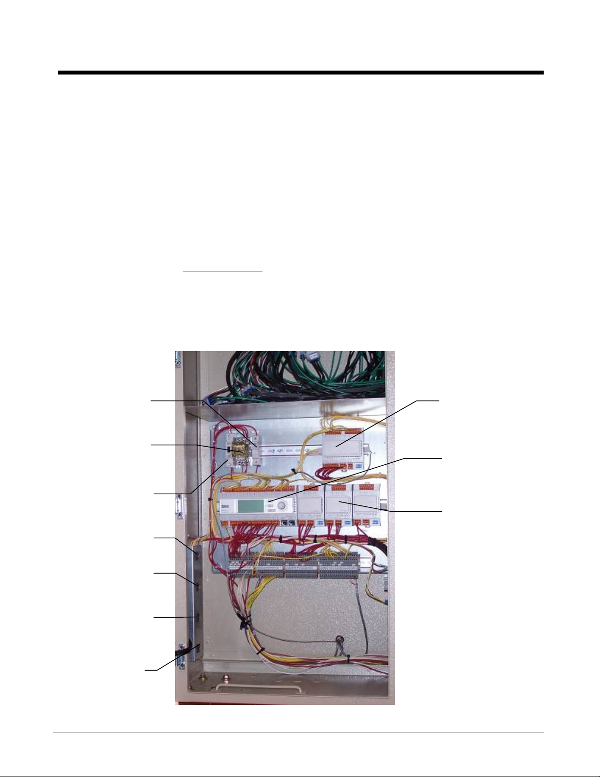
Control Panel Layout
Figure 1, Control Panel Components, Three-Circuit Unit, w/o VFD
Controller
Fuse
Emergency
Switch
Relay
Control
Circuit
Breaker
Unit On/Off
Circuit #1
Pumpdown
Circuit #2
Pumpdown
Switch
Circuit #3
Pumpdown
Switch
Alarm & Limit
Extension
Module
MicroTech III
Main
Controller
Fan Control
Extension
Modules
Emergency
Switch
Located on
Front Door
OM 1051-2 5
NOTES:
Fan
Circuit Breaker
s
1 per Fan
,
Circuit #
1
Circuit Breaker
Circuit Breaker
1. The Emergency Switch Relay de-energizes all circuit’s control power when activated, causing an
immediate compressor and fan shutdown. The red emergency button switch is located on the
front of the control panel door.
2. The control power transformer is located in the power panel adjacent to the control panel.
3. Additional extension (aka expansion) modules are located elsewhere on the chiller.
4. See the VFD section for a description of the panel used with the VFD option as it is considerably
different from the standard panel.
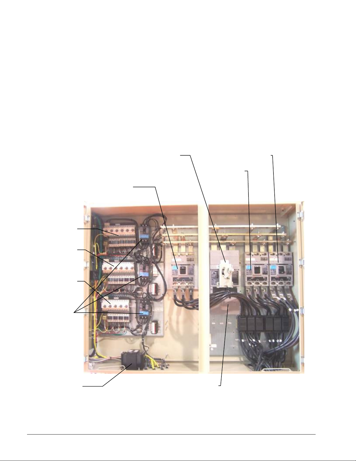
Power Panel Layout
The power panel is at the front of the unit, behind the two doors to the right.
Figure 2, Power Panel, Three-Circuit Units, w/o VFD
Fan Contactors
Fan Contactors
1 per Fan, Circuit #2
Fan Contactors
1 per Fan, Circuit #3
Compressor #1
Circuit Breaker
Single Point
Disconnect Switch with
Compressor #3
Compressor #2
6 OM 1051-2
Line/120V
Transformer
Incoming Power
Connections
NOTE: See the VFD section of this manual for a description of the power used with the VFD option
as it is considerably different from the standard panel.
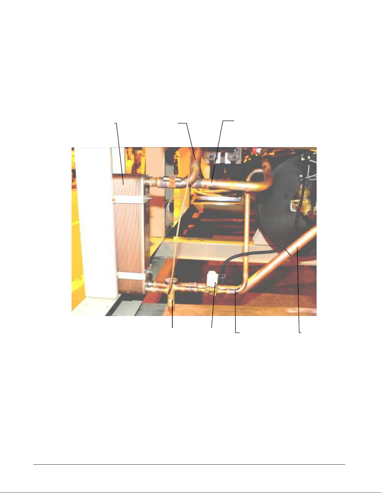
Economizer Components
The chiller may or may not have economizers depending on design capacity
requirements. An economizer is a well-proven device to increase a refrigerant circuit’s
capacity and efficiency.
Figure 3, Economizer Components
Brazed-plate
Heat Exchanger
Gas to Comp.
Interstage
Liquid from
Condenser
TXV LLSV
Warm liquid from the condenser is fed into the economizer where it is cooled by flashing off
liquid also from the condenser. The flash gas is piped to a compressor interstage point.
Lowering the liquid refrigerant temperature to the evaporator decreases its enthalpy (heat
content) and results in a greater amount of heat absorption from the chilled water.
OM 1051-2 7
Liquid Feed
to
Economizer
Liquid Feed
to
Evaporator
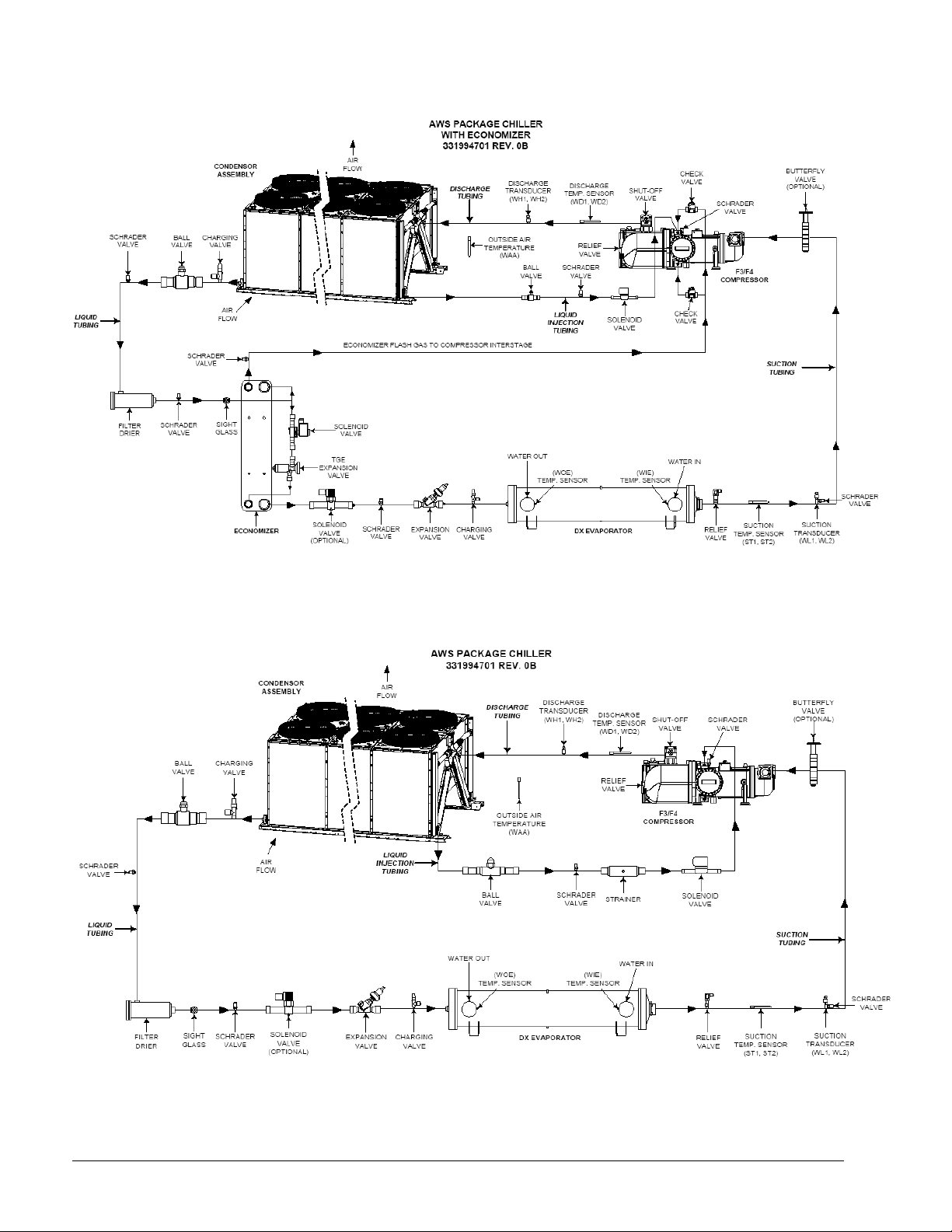
Figure 4, Piping Schematic with Economizer Circuit, One Circuit Shown
Figure 5, Piping Schematic without Economizer Circuit, One Circuit Shown
8 OM 1051-2
Controller Description
Hardware Structure
The MicroTech III control system for Pathfinder chillers consists of a main unit controller with a
number of extension input/output I/O modules attached depending on the chiller size and
configuration.
One of the optional BAS communication modules may be included.
An optional Remote Operator Interface panel may be included, connected with up to nine
Pathfinder units.
The MicroTech III controllers used on Pathfinder chillers are not interchangeable with previous
MicroTech II controllers.
MicroTech III unit controller
Remote Operator Interface
BACnet/
MSTP
Communication
MODbus LON
BACnet/IP
Extension I/O Modules
OM 1051-2 9

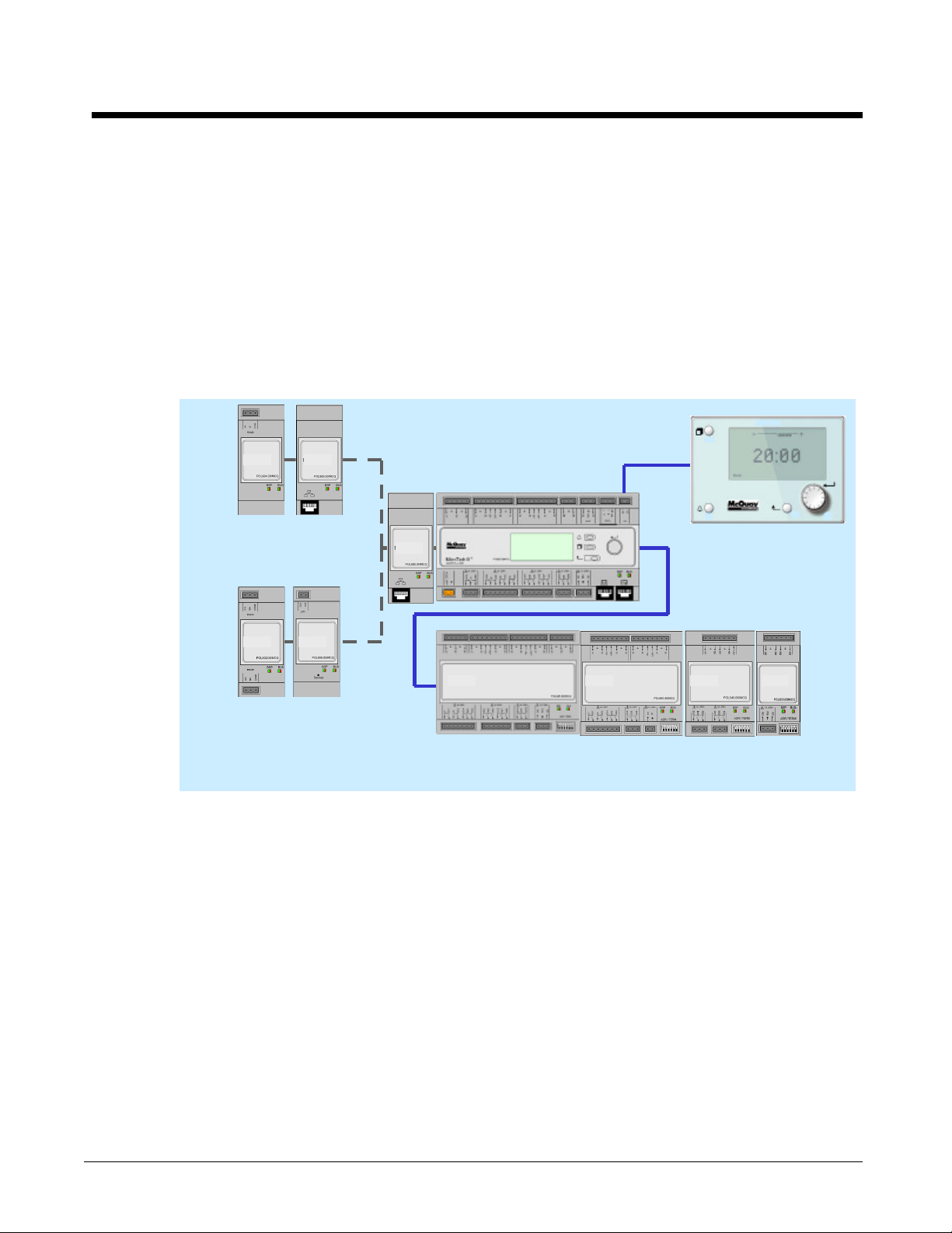
System Architecture
The overall controls architecture uses the following:
• One MicroTech III main controller
• I/O extension modules (sometimes referred to as “controllers”) as needed depending
on the configuration of the unit
• Optional BAS interface as selected
Figure 6, System Architecture
BAS Interface
(BACnet, Lon,
Modbus)
MicroTech III Main Controller
Peripheral Bus
I/O Extension
Alarm/Limiting
I/O Extension
Compressor 1
I/O Extension
Compressor 2
I/O Extension
Compressor 3
I/O Extension
Fans Circuit 1
and 2
I/O Extension
EXV 1
I/O Extension
EXV 2
I/O Extension
EXV 3
I/O Extension
Fans Circuit 3
I/O Extension
Fans Circuit 3
and 4
I/O Extension
Fans Circuit 4
I/O Extension
Compressor 4
I/O Extension
EXV 4
10 OM 1051-2
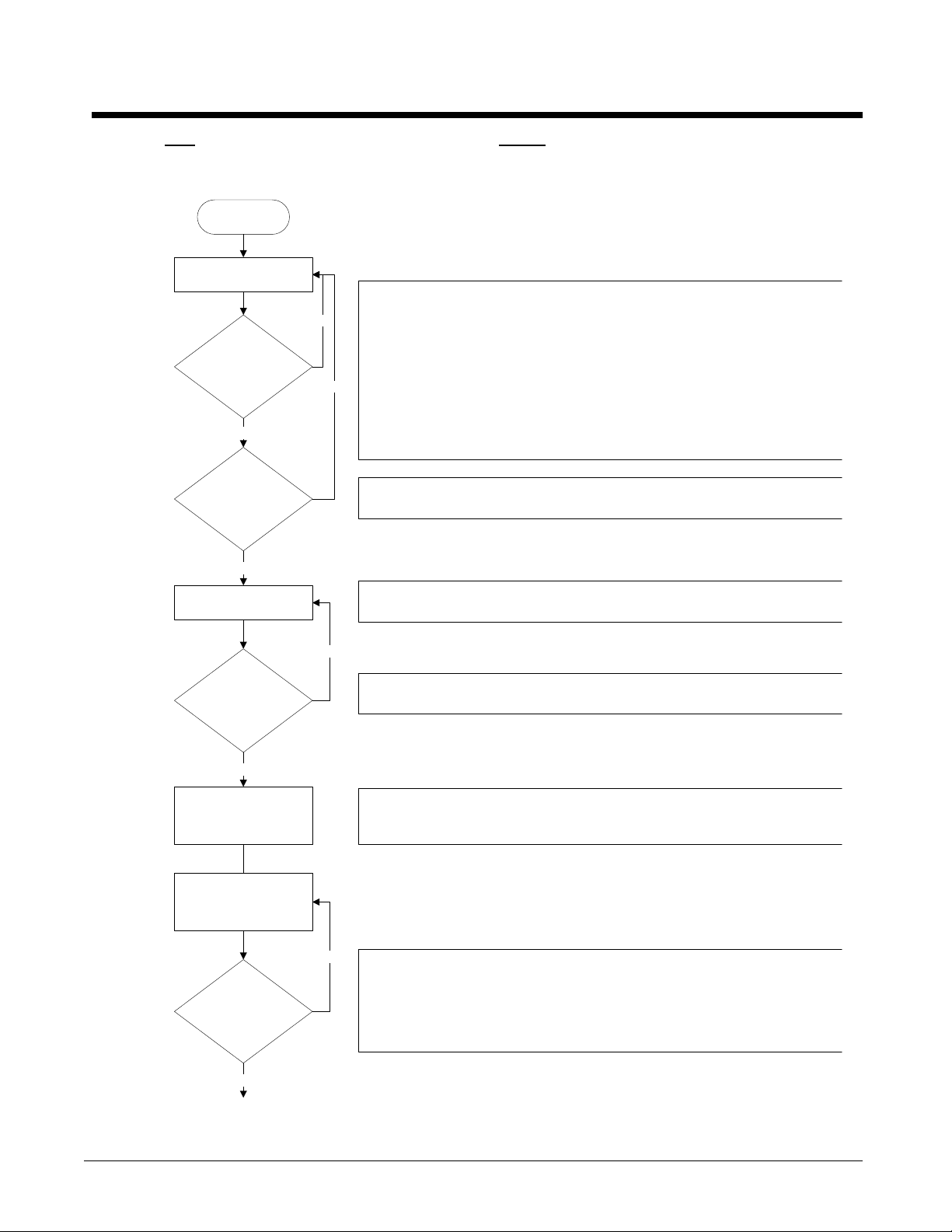
Sequence of Operation
Figure 7, Unit Sequence of Operation (see Figure 9 for circuit sequence of operation)
Unit power up
Unit in Off state
Is unit enabled?
Yes
Is low ambient lockout
active?
No
Evaporator pump output on
AWS Chiller Sequence of Operation in Cool Mode
The chiller may be disabled via the unit switch, the remote switch, the keypad
enable setting, or the BAS network. In addition, the chiller will be disabled if all
No
circuits are disabled, or if there is a unit alarm. If the chiller is disabled, the unit
status display will reflect this and also show why it is disabled.
If the unit switch is off, the unit status will be Off:Unit Switch. If the chiller is
disabled due to network command, the unit status will be Off:BAS Disable. When
Yes
the remote switch is open, the unit status will be Off:Remote Switch. When a unit
alarm is active, the unit status will be Off:Unit Alarm. In cases where no circuits
are enabled, the unit status will be Off:All Cir Disabled. If the unit is disabled via
the Chiller Enable set point, the unit status will be Off:Keypad Disable.
Low ambient lockout will prevent the chiller from starting even if it is otherwise
enabled. When this lockout is active, the unit status will be Off:Low OAT Lock.
If the chiller is enabled, then the unit will be in the Auto state and the evaporator
water pump output will be activated.
No
Is flow present?
Yes
Wait for chilled water loop to
recirculate.
Keep pump output on while
chiller is enabled and either
running or ready to run.
Is there enough load to
start chiller?
Yes
The chiller will then wait for the flow switch to close, during which time the unit
status will be Auto:Wait for flow.
After establishing flow, the chiller will wait some time to allow the chilled water loop
to recirculate for an accurate reading of the leaving water temperature. The unit
status during this time is Auto:Evap Recirc.
No
The chiller is now ready to start if enough load is present. If the LWT is not higher
than the Active Setpoint plus the Start Up Delta T, the unit status will be Auto:Wait
for load.
If the LWT is higher than the Active Setpoint plus the Start Up Delta T, the unit
status will be Auto. A circuit can start at this time.
OM 1051-2 11
12 OM 1051-2
OM 1051-2 13
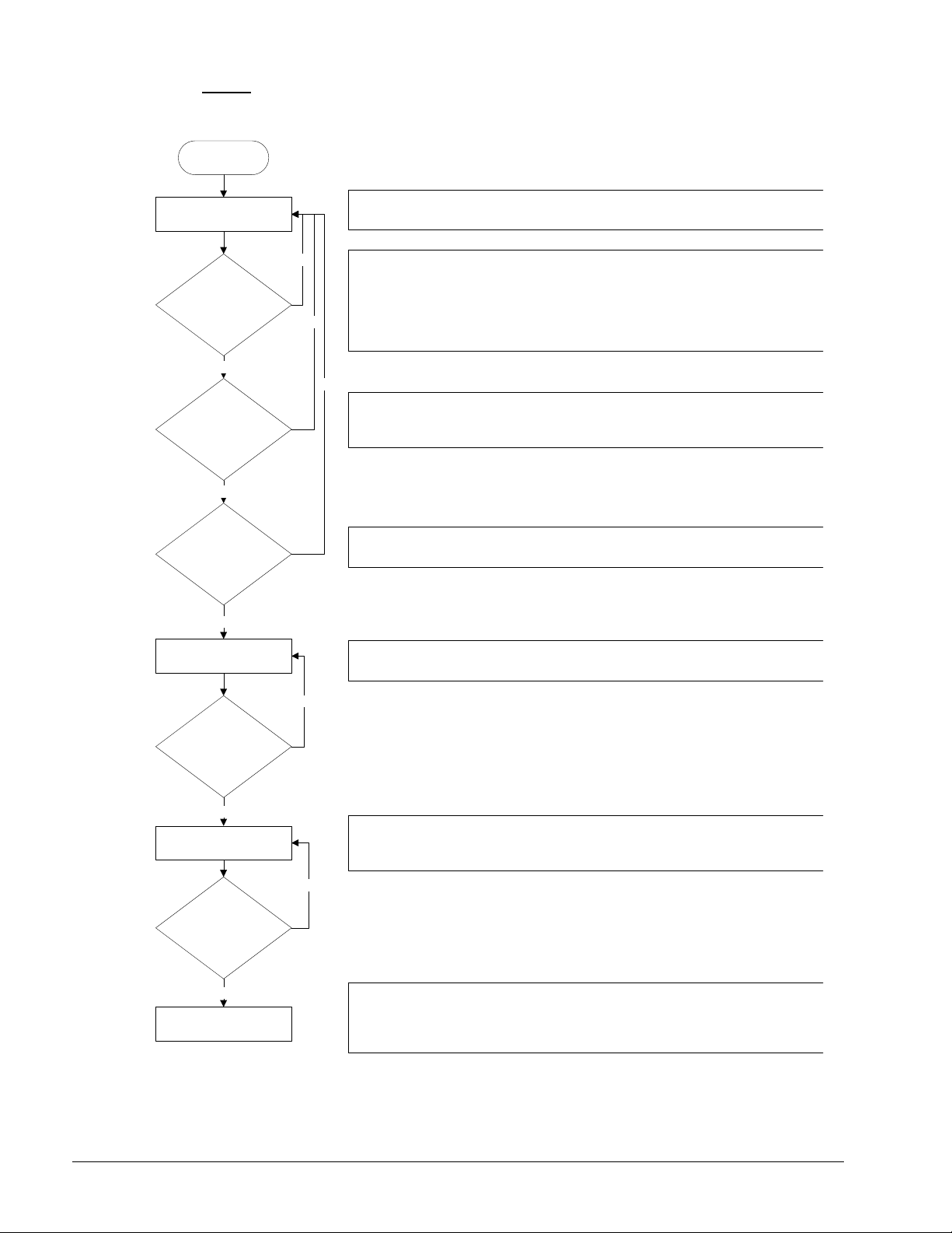
Figure 8, Circuit Sequence of Operation
Unit power up
Circuit is in Off state
Is circuit is enabled to
start?
Yes
Are compressor cycle
timers active?
No
Is compressor oil sump
ready?
No
AWS Sequence of Operation - Circuits
When the circuit is in the Off state the EXV is closed, compressor is off, and all fans
are off.
The circuit must be enabled before it can run. It may be disabled for several
reasons. When the circuit switch is off, the status will be Off:Circuit Switch.
If the BAS has disabled the circuit, the status will be Off:BAS Disable. If the circuit
Yes
has an active stop alarm then the status will be Off:Cir Alarm. If the circuit has
been disabled via the circuit mode set point, the status will be Off:Cir Mode
Disable.
No
A minimum time must pass between the previous start and stop of a compressor
and the next start. If this time has not passed, a cycle timer will be active and the
circuit status will be Off:Cycle Timer.
If the compressor is not ready due to refrigerant in the oil, the circuit cannot start.
The circuit status will be Off:Refr In Oil.
Yes
Circuit is ready to start
Is circuit commanded to
start?
Yes
Run circuit
Is circuit commanded to
shut down?
Yes
Pumpdown circuit
No
No
If the compressor is ready to start when needed, the circuit status will be
Off:Ready.
When the circuit begins to run, the compressor will be started and the EXV, fans,
and other devices will be controlled as needed. The normal circuit status at this
time will be Run.
When the circuit is commanded to shut down, a normal shut down of the circuit will
be performed. The circuit status during this time will be Run:Pumpdown. After
the shut down is completed, the circuit status will normally be Off:Cycle Timer
initially.
14 OM 1051-2
Controller Operation
MicroTech III Inputs/Outputs
I/O for the unit control and for circuits one and two are found on CP1.
The chiller may be equipped with two or three compressors.
Analog Inputs
# Description Signal Source Expected Range
AI1 Evaporator Entering Water Temp NTC Thermister (10K@25°C) -50°C – 120°C
AI2 Evaporator Leaving Water Temp NTC Thermister (10K@25°C) -50°C – 120°C
AI3 Evaporator #1 Leaving Water Temp (*) NTC Thermister (10K@25°C) -50°C – 120°C
X1 Evaporator #2 Leaving Water Temp (*) NTC Thermister (10K@25°C) -50°C – 120°C
X2 Outside Ambient Temperature NTC Thermister (10K@25°C) -50°C – 120°C
X4 LWT Reset 4-20 mA Current 1 to 23 mA
*Evaporator #1 LWT and Evaporator #2 LWT will only be used when unit is configured with
four circuits
Analog Outputs
# Description Output Signal Range
X5 Fan VFD #1 0-10VDC 0 to 100% (1000 steps resolution)
X6 Fan VFD #2 0-10VDC 0 to 100% (1000 steps resolution)
X7 Fan VFD #3 0-10VDC 0 to 100% (1000 steps resolution)
X8 Fan VFD #4 0-10VDC 0 to 100% (1000 steps resolution)
Digital Inputs
# Description Signal Off Signal On
DI1 Unit PVM Fault No Fault
DI2 Evaporator Flow Switch No Flow Flow
DI3 Double Setpoint/ Mode Switch Cool mode Ice mode
DI4 Remote Switch Remote off Remote on
DI5 Unit Switch Unit off Unit on
DI6 Emergency Stop Unit off/rapid stop Unit on
Digital Outputs
# Description Output OFF Output ON
DO1 Evaporator Water Pump Pump Off Pump On
Alarm Active
DO2 Unit Alarm Alarm not Active
DO3 Circuit #1 Fan Step #1 Fan Off Fan On
DO4 Circuit #1 Fan Step #2 Fan Off Fan On
DO5 Circuit #1 Fan Step #3 Fan Off Fan On
DO6 Circuit #1 Fan Step #4 Fan Off Fan On
DO7 Circuit #2 Fan Step #1 Fan Off Fan On
DO8 Circuit #2 Fan Step #2 Fan Off Fan On
DO9 Circuit #2 Fan Step #3 Fan Off Fan On
DO10 Circuit #2 Fan Step #4 Fan Off Fan On
(Flashing= circuit
alarm)
OM 1051-2 15
Expansion I/O Compressor #1 to #3
Analog Inputs
# Description Signal Source Expected Range
X1 Discharge Temperature NTC Thermister (10K@25°C) -50°C – 125°C
X2 Evaporator Pressure Ratiometric 0.5-4.5 Vdc -100 kPa to 700 kPa
X3 Oil Pressure Ratiometric 0.5-4.5 Vdc 0 kPa to 3000 kPa
X4 Condenser Pressure Ratiometric 0.5-4.5 Vdc 0 kPa to 3000 kPa
X7 Motor Temperature See note below
Note: European chillers will have the PTC thermistor in the compressor motor connected
to this input. X7 is configured as an NTC 10k input for European chillers.
Analog Outputs
# Description Output Signal Range
Not Needed
Digital Inputs
# Description Signal Off Signal On
X6 Starter Fault Fault No fault
X7 Motor Protection See note below
DI1 High Pressure Switch Fault No fault
Note: US chillers will use the motor protection board connected to this input. X7 is
configured as a digital input for US chillers.
Digital Outputs
Europe Configuration
# Description Output Off Output On
DO1 Start Compressor Compressor Off Compressor On
DO2 Economizer Solenoid Closed Solenoid Open
DO3 Non-modulating Slide Load/Unload Solenoid Closed Solenoid Open
DO4 Liquid Injection Solenoid Closed Solenoid Open
DO5 Modulating Slide Load Solenoid Closed Solenoid Open
DO6 Modulating Slide Unload Solenoid Closed Solenoid Open
X5 Modulating Slide “turbo” Solenoid Closed Solenoid Open
U.S. Configuration
# Description Output Off Output On
DO1 Start Compressor Compressor Off Compressor On
DO2 Economizer Solenoid Closed Solenoid Open
DO3 Non-modulating Slide Load Solenoid Closed Solenoid Open
DO4 Non-modulating Slide Unload Solenoid Closed Solenoid Open
DO5 Modulating Slide Load Solenoid Closed Solenoid Open
DO6 Modulating Slide Unload Solenoid Closed Solenoid Open
X5 Modulating Slide ‘Turbo’ Solenoid Closed Solenoid Open
X8 Liquid Injection Solenoid Closed Solenoid Open
16 OM 1051-2
I/O EXV Circuit #1 to #3
Analog Inputs
# Description Signal Source Expected Range
X2 Suction Temperature NTC Thermister 10K@25°C) -50°C – 120°C
X3 Slide Position LVDT 4 to 20 mA 0% to 100%
Analog Outputs
# Description Output Signal Range
Not Needed
Digital Inputs
# Description Signal Off Signal On
DI1 Low Pressure switch Fault No fault
Digital Outputs
# Description Output Off Output On
DO1 Liquid Line Solenoid Closed Solenoid Open
Stepper Motor Output
# Description
M1+
M1-
M2+
M2-
EXV Stepper Coil 1
EXV Stepper Coil 2
Extension I/O Fan Module Circuit #1 & 2
Digital Inputs
# Description Output Off Output On
DI1 PVM/GFP Circuit #1 Fault No fault
DI2 PVM/GFP Circuit #2 Fault No fault
Digital Outputs
# Description Output Off Output On
DO1 Circuit #1 Fan Step #5 Fan Off Fan On
DO2 Circuit #1 Fan Step #6 Fan Off Fan On
DO3 Circuit #2 Fan Step #5 Fan Off Fan On
DO4 Circuit #2 Fan Step #6 Fan Off Fan On
Extension I/O Fan Module Circuit #3
Digital Outputs
# Description Output Off Output On
DO1 Circuit #3 Fan Step #5 Fan Off Fan On
DO2 Circuit #3 Fan Step #6 Fan Off Fan On
Extension I/O Unit Alarm & Limiting
Analog Inputs
# Description Signal Source Range
X3 Demand Limit 4-20 mA 1 to 23 mA
X4 Unit Current 4-20 mA 1 to 23 mA
Analog Outputs
# Description Output Signal Range
Not Needed
OM 1051-2 17
Digital Inputs
# Description Signal Off Signal On
X1 External Alarm/Event
X2 Current Limit Enable No Limiting Limiting
X5 Circuit Switch #1 Circuit Off Circuit On
X6 Circuit Switch #2 Circuit Off Circuit On
X7 Circuit Switch #3 Circuit Off Circuit On
External Device
Failure
External Device OK
Digital Outputs
# Description Output Off Output On
DO1 Evaporator Water Pump #2 Pump Off Pump On
DO2 Open
DO3 Circuit #1 Alarm No Alarm Alarm
DO4 Circuit #2 Alarm No Alarm Alarm
DO5 Circuit #3 Alarm No Alarm Alarm
Setpoints
The following parameters are remembered during power off, are factory set to the Default value,
and can be adjusted to any value in the Range column.
Read and write access to these setpoint is determined by the Global HMI (Human Machine
Interface) Standard Specification.
Table 1, Setpoint Default and Range
Description Default Range
Unit
Manufacturing Location
Frequency
Voltage
Unit Enable
Unit Status after Power
Failure
Not Selected
60 Hz
460 V
Enable
Not Selected, Europe, USA
50, 60
230, 380, 400, 460, 575
Disable, Enable
Enable Disable, Enable
Control source Local Local, Network
Available Modes Cool
Cool LWT 1
Cool LWT 2
Cool LWT 1 with Glycol
Cool LWT 2 with Glycol
Ice LWT
7.0°C (44.6°F)
7.0°C (44.6°F)
7.0°C (44.6°F)
7.0°C (44.6°F)
-4.0°C (24.8°F)
4.0°C to 15.0°C (39.2°F to 59.0°F)
4.0°C to 15.0°C (39.2°F to 59.0°F)
-4.0°C to 15.0°C (24.8°F to 59.0°F)
-4.0°C to 15.0°C (24.8°F to 59.0°F)
Cool, Cool w/Glycol
Cool/Ice w/Glycol, Ice, Test
-8.0°C to 4.0°C (17.6°F to 39.2°F)
Startup Delta T 2.7 deg C (4.9 deg F) 0 to 5.0 deg C (0 to 9.0 deg F)
Shut Down Delta T 1.5 deg C (2.7 deg F) 0 to 1.7 deg C (0 to 3.1 deg F)
Stage Up Delta T 0.5 deg C (0.9 deg F) 0 to 1.7 deg C (0 to 3.1 deg F)
Stage Down Delta T 0.7 deg C (1.3 deg F) 0 to 1.7 deg C (0 to 3.1 deg F)
Max Pulldown
1.7 deg C/min
(3.1 deg F/min)
0.3 to 2.7 deg C/min
(0.5 to 4.9 deg F/min)
Continued next page.
Description Default Range
Nominal Evap Delta T 2 Cir 5.6 deg C (10.1 deg F) 3.3 to 8.9 deg C (5.9 to 16.0 deg F)
Nominal Evap Delta T 3 Cir 5.6 deg C (10.1 deg F) 3.3 to 10 deg C (5.9 to 18.0 deg F)
Variable Evap Flow No No, Yes
18 OM 1051-2
Evap Recirc Timer 30 sec 0 to 300 seconds
Pump Control #1 Only
#1 Only, #2 Only, Auto,
#1 Primary, #2 Primary
LWT Reset Type None None, 4-20mA, OAT
Max Reset 5.0 deg C (9.0 deg F) 0 to 10.0 deg C (0 to 18.0 deg F)
Start Reset Delta T 5.0 deg C (9.0 deg F) 0 to 10.0 deg C (0 to 18.0 deg F)
Max Reset OAT
Start Reset OAT
15.5°C (59.9°F)
23.8°C (74.8°F)
10.0°C to 30.0°C (50°F to 86.0 °F)
10.0°C to 30.0°C (50°F to 86.0 °F)
Soft Load Off Off, On
Begin Capacity Limit 40% 20-100%
Soft Load Ramp 20 min 1-60 minutes
Demand Limit Off Off, On
Current @ 20mA 800 A 0 to 2000 A
Current limit Setpoint 800 A 0 to 2000 A
# of Circuits 2 2, 3
Ice Delay Timer 12 hrs 1-23 hours
Clear Ice Timer No No, Yes
PVM Multi Point Single Point, Multi Point , None(SSS)
Noise Reduction Disabled Disabled, Enabled
Noise Reduction Start Time 21:00 18:00 – 23:59
Noise Reduction End Time 6:00 5:00 – 9:59
Noise Reduction Offset 5.0 deg C (9.0 deg F) 0 to 14.0 deg C (0 to 25.2 deg F)
Evap LWT Sensor Offset 0 deg C (0 deg F) -5.0 to 5.0 deg C (-9.0 to 9.0 deg F)
Evap EWT Sensor Offset 0 deg C (0 deg F) -5.0 to 5.0 deg C (-9.0 to 9.0 deg F)
OAT Sensor Offset 0 deg C (0 deg F) -5.0 to 5.0 deg C (-9.0 to 9.0 deg F)
Compressors-Global
Start-start timer 20 min 15-60 minutes
Stop-start timer 5 min 3-20 minutes
Pumpdown Pressure 100 kPa (14.5 psi) 70 to 280 kPa (10.2 to 40.6 psi)
Pumpdown Time Limit 120 sec 0 to 180 sec
Light Load Stage Down 40% 26 to 50%
High Load Stage Up 80% 50 to 100%
Stage Up Time 5 min 0 to 60 min
Stage Down Time 3 min 3 to 30 min
Stage Delay Clear No No, Yes
Soft Load Off Off, On
Max # Comps Running 2 2,3
Sequence # Cir 1 1 1-3
Sequence # Cir 2 1 1-3
Sequence # Cir 3 1 1-3
Liquid Injection Activation
85.0°C (185.0°F)
50.0°C to 110.0°C (122.0°C to 230.0°F)
Liq. Line Solenoid Valves No No, Yes
Slide Position Sensors Yes No, Yes
Continued next page.
OM 1051-2 19
Description Default Range
Alarm Limits
Low Pressure-Unload 160 kPa (23 psi) 160 kPa to 310 kPa (23 psi to 48 psi)
Low Pressure-Hold 180 kPa (26 psi) 180 kPa to 310 kPa (26 psi to 48 psi)
Low Press-Unload w/ Glycol 160 kPa (23 psi) 0 kPa to 310 kPa (0 psi to 48 psi)
Low Press-Hold w/Glycol 180 kPa (26 psi) 0 kPa to 310 kPa (0 psi to 48 psi)
High Oil Press Diff Delay 30 sec 10-180 sec
High Oil Press Differential 250 kPa (36 psi) 0 to 415 kPa (0 to 60 psi)
High Discharge Temperature 110.0°C (230.0°F) 65.0 to 110.0 °C (149.0 to 230.0°F)
High Cond Pressure Delay 5 sec 0 to 30 sec
Low Pressure Ratio Delay 90 sec 0 to 180 sec
Start Time Limit 60 sec 20 to 180 sec
Evap. Water Freeze
Evap. Water Freeze w/ Glycol
2.2°C (36.0°F)
2.2°C (36.0°F)
1.1°C to 6.0°C (34.0°F to 42.8°F)
-18.0°C to 6.0°C (-0.4°F to 42.8°F)
Evaporator Flow Proof 15 sec 5 to 15 sec
Recirculate Timeout 3 min 1 to 10 min
Low OAT Lockout
Low OAT Lockout/with
Fan VFD
12.0°C (53.6°F)
12.0°C (53.6°F)
2.0°C to 15.0°C (35.6°F to 59.0°F)
-23.0°C to 15.0°C (-9.4°F to 59.0°F)
The following setpoints exist individually for each circuit:
Description
Default Range
Circuit mode Enable Disable, enable, test
Compressor Size for Non-VFD HSA204
Compressor Size for VFD HSV204
HSA192, HSA204, HSA215
HSA232, HSA241, HSA263
HSV204, HSV215
HSV232, HSV241, HSV263
Economizer (VFD Only) With With, Without
Capacity Control Auto Auto, Manual
Manual Capacity See Note 1 0 to 100%
Clear Cycle Timers No No, Yes
EXV control Auto Auto, manual
Service Pumpdown No No, Yes
Economizer Enable Capacity
(VFD Model Only)
40% 40 to 75%
Evap pressure Sensor offset 0 kPa (0 psi) -100 to 100 kPa (-14.5 to 14.5 psi)
Cond pressure Sensor offset 0 kPa (0 psi) -100 to 100 kPa (-14.5 to 14.5 psi)
Oil pressure Sensor Offset 0 kPa (0 psi) -100 to 100 kPa (-14.5 to 14.5 psi)
Suction temp Sensor Offset 0 deg C (0 deg F) -5.0 to 5.0 deg C (-9.0 to 9.0 deg F)
Discharge temp offset 0 deg C (0 deg F) -5.0 to 5.0 deg C (-9.0 to 9.0 deg F)
Slide sensor mA @ minimum
Slide sensor mA @ maximum
4 mA 4 to 22 mA
20 mA 4 to 22 mA
Fans
Fan VFD enable Enable Disable, Enable
Number of fans 5 5 to 12
Saturated Condenser Temp
Target Min
Saturated Condenser Temp
Target Max
32.0°C (89.6°F)
43.0°C (109.4°F)
20.0°C to 50.0°C (68.0°F to
122.0°F)
32.0°C to 50.0°C (89.6°F to
122.0°F)
Continued next page.
20 OM 1051-2
Description Default Range
Fan Stage 0 Up Deadband 2.5 deg C (4.5 deg F) 1.0 to 10.0 deg C (1.8 to 18 deg F)
Fan Stage 1 Up Deadband 2.5 deg C (4.5 deg F) 1.0 to 10.0 deg C (1.8 to 18 deg F)
Fan Stage 2 Up Deadband 4.0 deg C (7.2 deg F) 1.0 to 10.0 deg C (1.8 to 18 deg F)
Fan Stage 3 Up Deadband 5.0 deg C (9.0 deg F) 1.0 to 10.0 deg C (1.8 to 18 deg F)
Fan Stage 4 Up Deadband 4.0 deg C (7.2 deg F) 1.0 to 10.0 deg C (1.8 to 18 deg F)
Fan Stage 5 to 12
Up Deadband
4.0 deg C (7.2 deg F) 1.0 to 10.0 deg C (1.8 to 18 deg F)
Fan Stage 1 Down Deadband 10.0 deg C (18.0 deg F) 1.0 to 10.0 deg C (1.8 to 18 deg F)
Fan Stage 2 Down Deadband 4.0 deg C (7.2 deg F) 1.0 to 10.0 deg C (1.8 to 18 deg F)
Fan Stage 3 Down Deadband 3.5 deg C (6.3 deg F) 1.0 to 10.0 deg C (1.8 to 18 deg F)
Fan Stage 4 Down Deadband 3.0 deg C (5.4 deg F) 1.0 to 10.0 deg C (1.8 to 18 deg F)
Fan Stage 5 Down Deadband 2.5 deg C (4.5 deg F) 1.0 to 10.0 deg C (1.8 to 18 deg F)
Fan Stage 6 to 12
Down Deadband
2.5 deg C (4.5 deg F) 1.0 to 10.0 deg C (1.8 to 18 deg F)
Fan VFD Max Speed 100% 90 to 110%
Fan VFD Min Speed 25% 20 to 60%
Dynamic Default Values
The fan staging dead bands have different default values based on the VFD enable setpoint.
When the VFD enable setpoint is changed, a set of default values for the fan staging dead bands
is loaded as follows:
Fan VFD is Enabled
Setpoint
Default
loaded (oF)
Stage 0 On Deadband 4.5 Stage 0 On Deadband 7.2
Stage 1 On Deadband 4.5 Stage 1 On Deadband 9.0
Stage 2 On Deadband 7.2 Stage 2 On Deadband 9.9
Stage 3 On Deadband 9.0 Stage 3 On Deadband 10.8
Stage 4 On Deadband 7.2 Stage 4 On Deadband 11.7
Stage 5 On Deadband 7.2 Stage 5 On Deadband 11.7
Stage 2 Off Deadband 7.2 Stage 2 Off Deadband 18
Stage 3 Off Deadband 6.3 Stage 3 Off Deadband 14.4
Stage 4 Off Deadband 5.4 Stage 4 Off Deadband 9.9
Stage 5 Off Deadband 4.5 Stage 5 Off Deadband 7.2
Stage 6 Off Deadband 4.5 Stage 6 Off Deadband 7.2
The low pressure settings have different default values based on the Manufacturing Location
setpoint. When the manufacturing location is configured, the default values for these setting are
loaded as shown below:
US Chiller
Setpoint Default loaded
Low Evap Press.Unload 160 kPa (23.2 psi) Low Evap Press. Unload 160 kPa (23.2 psi)
Low Evap Press.-Hold 180 kPa (26.1 psi) Low Evap Pressure-Hold 180 kPa (26.1 psi)
Fan VFD is Disabled
Setpoint
Default
loaded (oF)
European Chiller
Setpoint Default loaded
OM 1051-2 21
Unit Functions
Calculations
EWT Slope
EWT slope is calculated such that the slope represents the change in EWT over a time frame
of one minute.
Pulldown Rate
The slope value calculated above will be a negative value as the water temperature is
dropping. A pulldown rate is calculated by inverting the slope value and limiting to a
minimum value of 0°C/min.
Unit Availability
The unit is available to start if the following conditions are true:
1. Unit switch is closed
2. If unit mode is ice and the ice timer has timed out.
3. No unit alarms exist
4. Emergency stop input is closed
5. At least one circuit is enabled
6. Unit enable setpoint is Enable
7. If remote control is connected and remote unit switch is closed
8. If Control Source = Network, BAS Enable = True
Enabling and disabling the chiller is accomplished using setpoints and inputs to the chiller.
The unit switch, remote switch input, and Unit Enable Setpoint all are required to be on for
the unit to be enabled when the control source is set to local. The same is true if the control
source is set to network, with the additional requirement that the BAS request must be on.
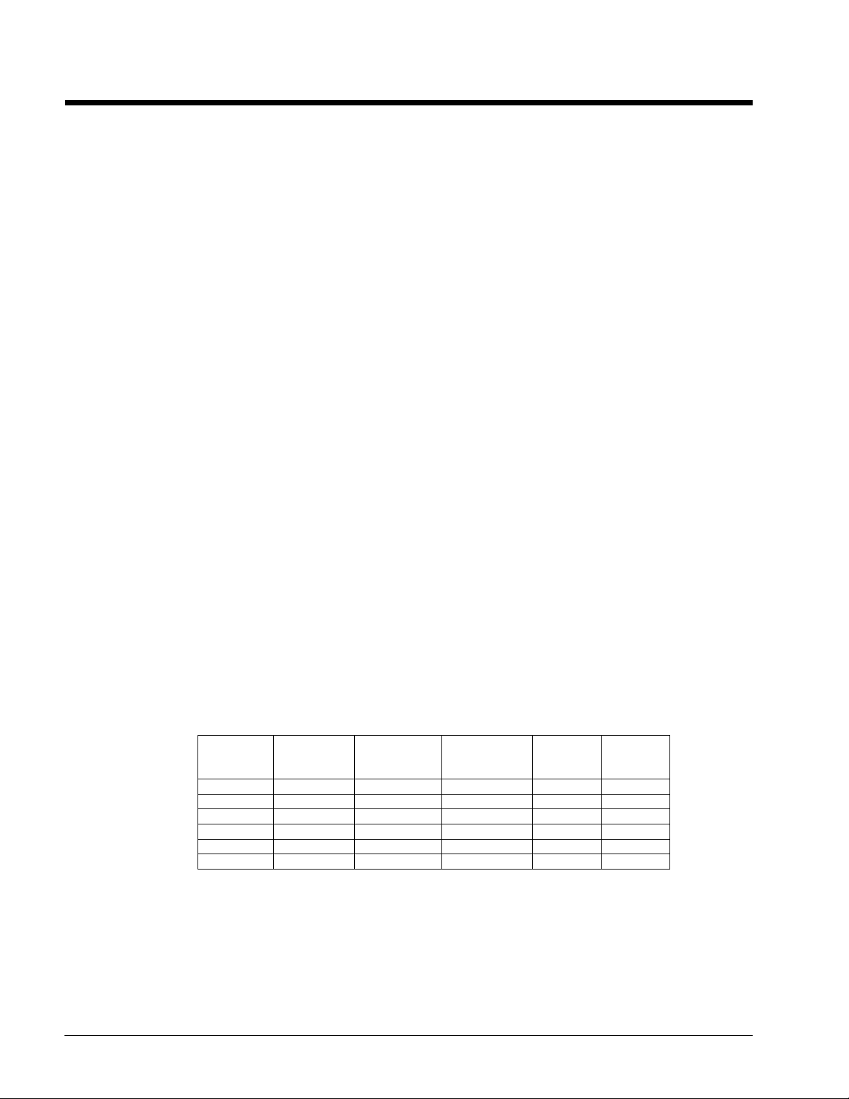
Unit is enabled according to the following table.
NOTE: An x indicates that the value is ignored.
Table 2, Enable Combinations
Unit
Switch
Off x x x x Off
x x Off x x Off
x x x Off x Off
On Local On On x On
x Network x x Off Off
On Network On On On On
Control
Source
Setpoint
Remote
Switch Input
Unit Enable
Setpoint
BAS
Request
Unit
Enable
All of the methods for disabling the chiller, discussed in this section, will cause a normal
shutdown (pumpdown) of any running circuits.
When the controller is powered up, the Unit Enable Setpoint will be initialized to ‘Disable’ if
the Unit Enable Init Setpoint is set to ‘Disable’.
.
22 OM 1051-2
Unit Mode Selection
The operating mode of the unit is determined by setpoints and inputs to the chiller. The
Available Modes Setpoint determines what modes of operation can be used. This setpoint
also determines whether the unit is configured for glycol use. The Control Source Setpoint
determines where a command to change modes will come from. A digital input switches
between cool mode and ice mode if they are available and the control source is set to local.
The BAS mode request switches between cool mode and ice mode if they are both available
and the control source is set to network.
The Available Modes Setpoint must only be changed when the unit switch is off. This is to
avoid changing modes of operation inadvertently while the chiller is running.
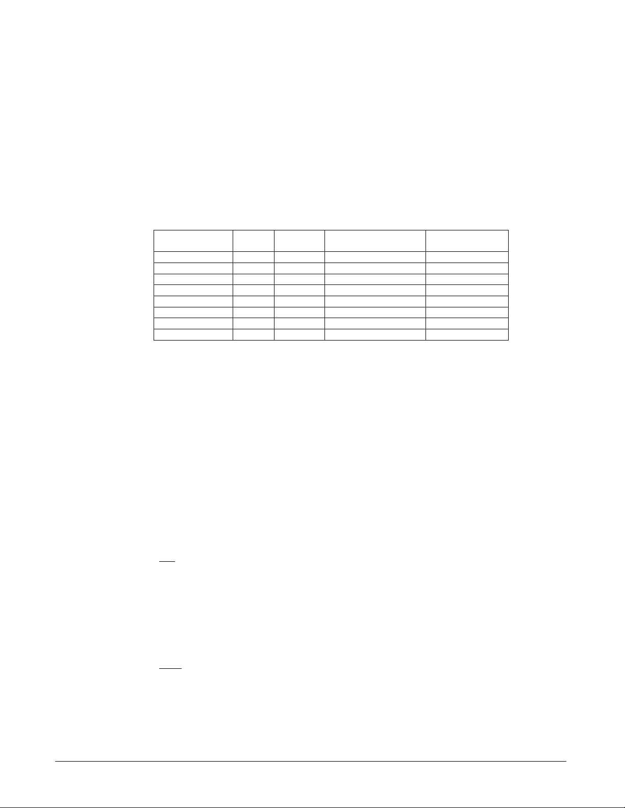
Unit Mode is set according to the following table.
Table 3, Mode Combinations
Control Source
Setpoint
x x x Cool Cool
x x x Cool w/Glycol Cool
Local Off x Cool/Ice w/Glycol Cool
Local On x Cool/Ice w/Glycol Ice
Network x Cool Cool/Ice w/Glycol Cool
Network x Ice Cool/Ice w/Glycol Ice
x x x Ice w/Glycol Ice
x x x Test Test
Notes
1. “x” Indicates that the value is ignored.
2. If the Available Modes Setpoint is set to an option ‘w/Glycol’, then glycol operation should be
enabled for the unit. Glycol operation should only be disabled when the Available Modes
Setpoint is set to ‘Cool’.
Mode
Input
BAS
Request
Available Modes
Setpoint
Unit Mode
Glycol Configuration
If the Available Modes Setpoint is set to an option w/Glycol, then glycol operation is
enabled for the unit. Glycol operation must be disabled only when the Available Modes
Setpoint is set to Cool.
Unit Control States
The unit will always be in one of three states:
• Off – Unit is not enabled to run.
• Auto – Unit is enabled to run.
• Pumpdown – Unit is doing a normal shutdown.
Off. The unit should be in the Off state if any of the following are true:
• A unit alarm is active
• All circuits are unavailable to start (cannot start even after cycle timers have expired)
• The unit mode is ice, all circuits are off, and the ice mode delay is active
• Manufacturing Location is not set
• Either manufacturing location or number of circuits have been changed and controller
has not been rebooted
Auto. The unit should be in the Auto state if all of the following are true:
• Manufacturing location is set and controller has been rebooted
• Unit enabled based on settings and switches
• If unit mode is ice, the ice timer has expired
• No unit alarms are active
• At least one circuit is enabled and available to start
OM 1051-2 23
Pumpdown. The unit should be in Pumpdown until all running compressors finish
pumping down if any of the following are true:
• Unit is disabled via settings and/or inputs in section Unit Availability.
• Unit pumpdown alarm is triggered
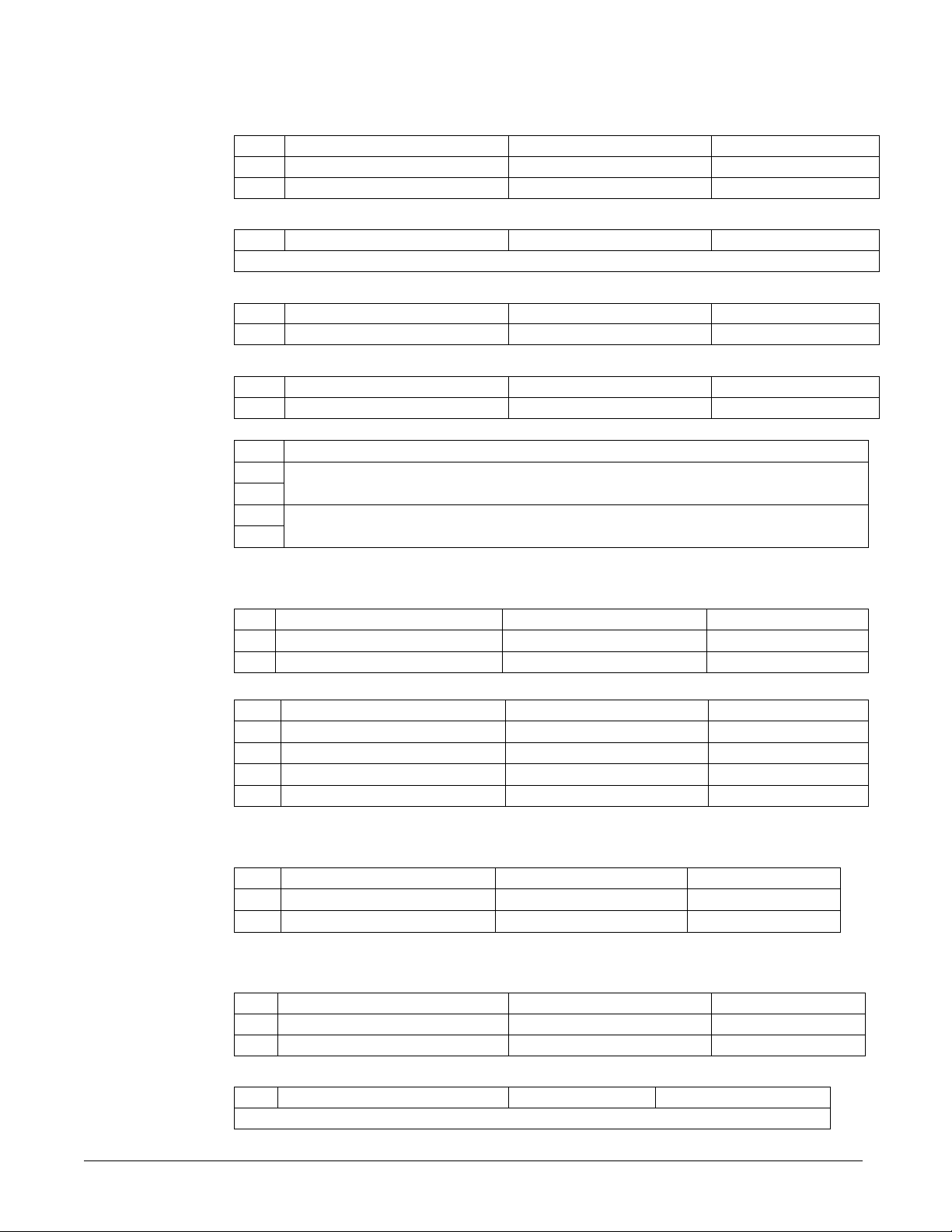
Unit Status
The displayed unit status is determined by the conditions in the following table:
Table 4, Unit Status
Enum
0 Auto Unit State = Auto
1 Off: Ice Mode Tmr
2 Off: OAT Lockout Unit State = Off and Low OAT Lockout is active
3 Off: All Cir Disabled Unit State = Off and all compressors unavailable
4 Off: Unit Alarm Unit State = Off and Unit Alarm active
5 Off: Keypad Disable Unit State = Off and Unit Enable Setpoint = Disable
6 Off: Remote Sw Unit State = Off and Remote Switch is open
7 Off: BAS Disable
8 Off: Unit Sw Unit State = Off and Unit Switch = Disable
9 Off: Test Mode Unit State = Off and Unit Mode = Test
10 Auto: Noise Reduction Unit State = Auto and Noise Reduction is active
11 Auto: Wait for Load
12 Auto: Evap Recirc Unit State = Auto and Evaporator State = Start
13 Auto: Wait for flow
14 Auto: Pumpdn Unit State = Pumpdown
15 Auto: Max Pulldn
16 Auto: Unit Cap Limit
17 Auto: Current Limit
18 Off. Cfg Chg, Rst Ctlr
19 Off Mfg Loc Not Set Mfg Location is not set
Status Conditions
Unit State = Off, Unit Mode = Ice, and Ice Delay =
Active
Unit State = Off, Control Source = Network, and BAS
Enable = false
Unit State = Auto, no circuits running, and LWT is
less than the active setpoint + startup delta
Unit State = Auto, Evaporator State = Start, and Flow
Switch is open
Unit State = Auto, max pulldown rate has been met or
exceeded
Unit State = Auto, unit capacity limit has been met or
exceeded
Unit State = Auto, unit current limit has been met or
exceeded
Unit configuration setpoint has changed, and reboot
of controller is required
Ice Mode Start Delay
Compressor Staging in Ice Mode
The first compressor will start when evaporator LWT is higher than the target plus the
Startup Delta T setpoint.
When at least one compressor is running, the other compressors will start only when
evaporator LWT is higher than the target plus the Stage Up Delta T setpoint.
All compressors will be staged off when evaporator LWT is less than the target.
Stage Up Delay
A fixed stage up delay of one minute between compressor starts is used in this mode.
When at least one compressor is running, the other compressors will start as quickly as
possible with respect to the stage up delay.
An adjustable start-to-start ice delay timer will limit the frequency with which the chiller
may start in Ice mode. The timer starts when the first compressor starts while the unit is
in ice mode. While this timer is active, the chiller cannot restart in Ice mode. The time
delay is user adjustable.
24 OM 1051-2

The ice delay timer may be manually cleared to force a restart in ice mode. A setpoint
specifically for clearing the ice mode delay is available. In addition, cycling the power to
the controller will clear the ice delay timer.
Evaporator Pump Control
State
Three evaporator pump control states for control of the evaporator pumps:
• Off - No pump on.
• Start – Pump is on, water loop is being recirculated. Recirc timer runnning
• Run – Pump is on, water loop has been recirculated. Recirc timer has timed out
Off The control state is Off when all of the following are true:
• Unit state is Off
• LWT is higher than the Evap Freeze setpoint or LWT sensor fault is active
• EWT is higher than the Evap Freeze setpoint or EWT sensor fault is active
Start. The control state is Start when any of the following are true:
• The unit state is auto
• LWT is less than the Evap Freeze setpoint and LWT sensor fault isn’t active
• EWT is less than the Evap Freeze setpoint and EWT sensor fault isn’t active
Run. The control state is Run when
• The flow switch input has been closed for a time greater than the Evaporator
Recirculate setpoint.
• The flow switch fault is not active
Pump Selection
The pump output used is determined by the Evap Pump Control setpoint. This setting
allows the following configurations:
• #1 only – Pump 1 will always be used
• #2 only – Pump 2 will always be used
• Auto – The primary pump is the one with the least run hours, the other is used as
a backup
• #1 Primary – Pump 1 is used normally, with pump 2 as a backup
• #2 Primary – Pump 2 is used normally, with pump 1 as a backup
Primary/Standby Pump Staging
The standby pump will be on if either of the following are true:
• Pump state is Run and the flow switch is open for Evap Proof Time/2
• Pump start is start and Recirculate timeout has expired.
Auto Control
If auto pump control is selected, the primary/standby logic above is still used. When the
evaporator is not in the run state, the run hours of the pumps will be compared. The
pump with the least hours will be designated as the primary at this time.
Noise Reduction
Noise Reduction is an operating mode designed to reduce unit sound levels by decreasing
compressor and fan operating time. It is used during the night when the cooling load is
usually reduced and the ambient temperature is lower.
Noise Reduction always requires the Noise Reduction setpoint to be set to ‘enable’. If it
is set to ‘disable’, it will not activate for any reason.
Assuming this functionality is enabled, there are two ways it can become active:
OM 1051-2 25

• If the unit mode is cool, and the unit controller clock time is between the Noise
Reduction start time and end time
• Control Source setpoint is set to network, and the BAS command is ‘enable’
When Noise Reduction is active, the Maximum Reset is applied to the cool LWT
setpoint. However, if any reset type is selected, that reset will continue to be used rather
than the Maximum Reset. Also, the saturated condenser target for each circuit will be
offset by the Noise Reduction Condenser Target Offset.
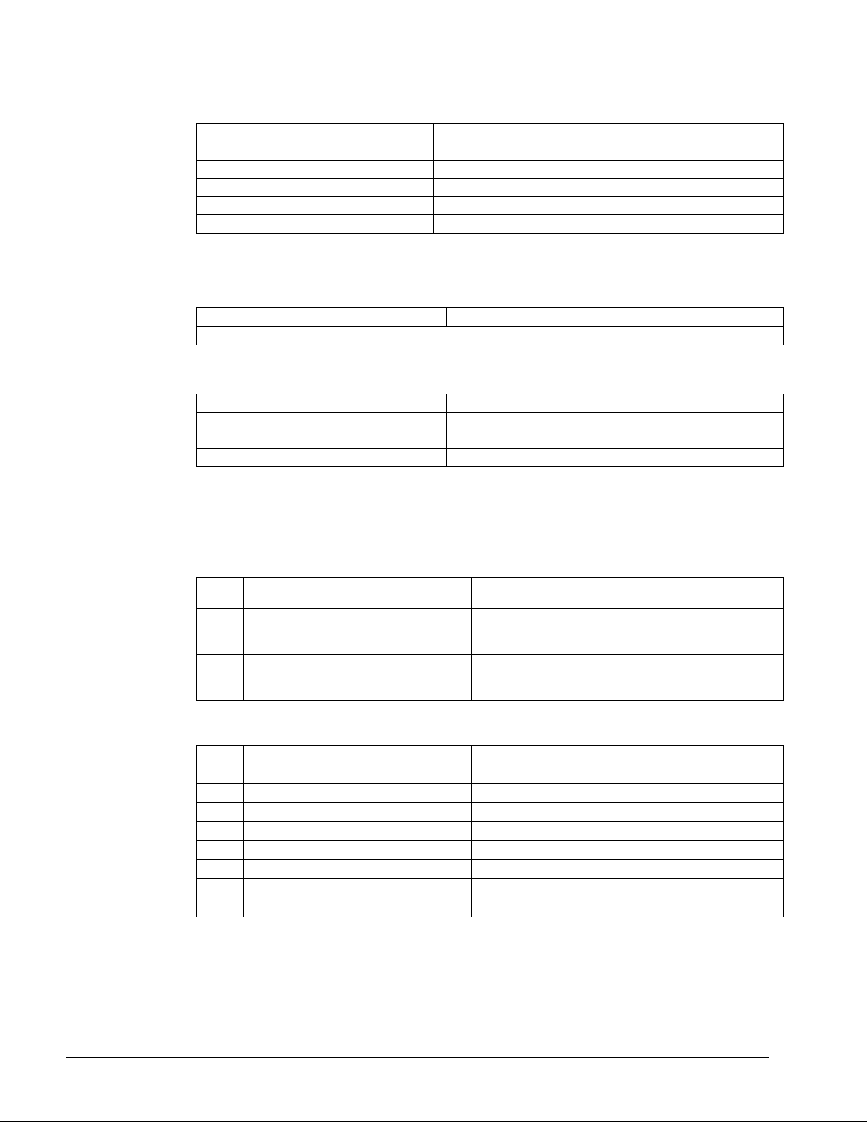
Leaving Water Temperature (LWT) Reset
LWT Target
The LWT Target varies based on settings and inputs and is selected as follows:
Table 5, Leaving Water Temperature Targets
Control Source
Setpoint
Local
Network X X
Local
Network X X
Local
Network
Local x x Ice Setpoint
Network x x
Mode
Input
OFF X Cool Setpoint 1
ON X Cool Setpoint 2
OFF X Cool Setpoint 1
ON X Cool Setpoint 2
OFF x Cool Setpoint 1
ON x Ice Setpoint
x COOL BAS Cool Setpoint
x ICE
BAS
Request
Available Modes
Setpoint
COOL
COOL w/Glycol
COOL/ICE w/Glycol
ICE w/Glycol
Base LWT Target
BAS Cool Setpoint
BAS Cool Setpoint
BAS Ice Setpoint
BAS Ice Setpoint
Leaving Water Temperature (LWT) Reset
The base LWT target may be reset if the unit is in Cool mode and it is configured for a
reset. The type of reset to be used is determined by the LWT Reset Type setpoint.
When the active reset increases, the Active LWT Target is changed at a rate of
0.2 degrees F every 10 seconds. When the active reset decreases, the Active LWT Target
is changed all at once.
After resets are applied, the LWT target can never exceed a value of 60°F.
Reset Type – None
The Active Leaving Water variable is set equal to the current LWT setpoint.
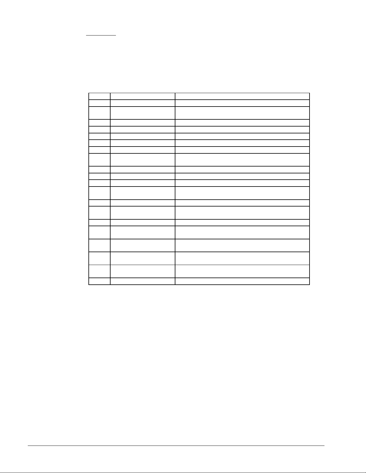
Reset Type – Return Chilled Water
The Active Leaving Water variable is adjusted by the return water temperature.
Return Reset
LWT set Point+Max Reset
Active
LWT
(oF)
(54)
Max Reset
(10)
LWT Set Point
(44)
0
Evap Delta T (oF)
Start Reset Delta T
26 OM 1051-2
The active setpoint is reset using the following parameters:
1. Cool LWT setpoint
2. Max Reset setpoint
3. Start Reset Delta T setpoint
4. Evap Delta T
Reset varies from 0 to Max Reset setpoint as the Evaporator EWT – LWT (Evap delta t)
varies from the Start Reset Delta T set-point to 0.
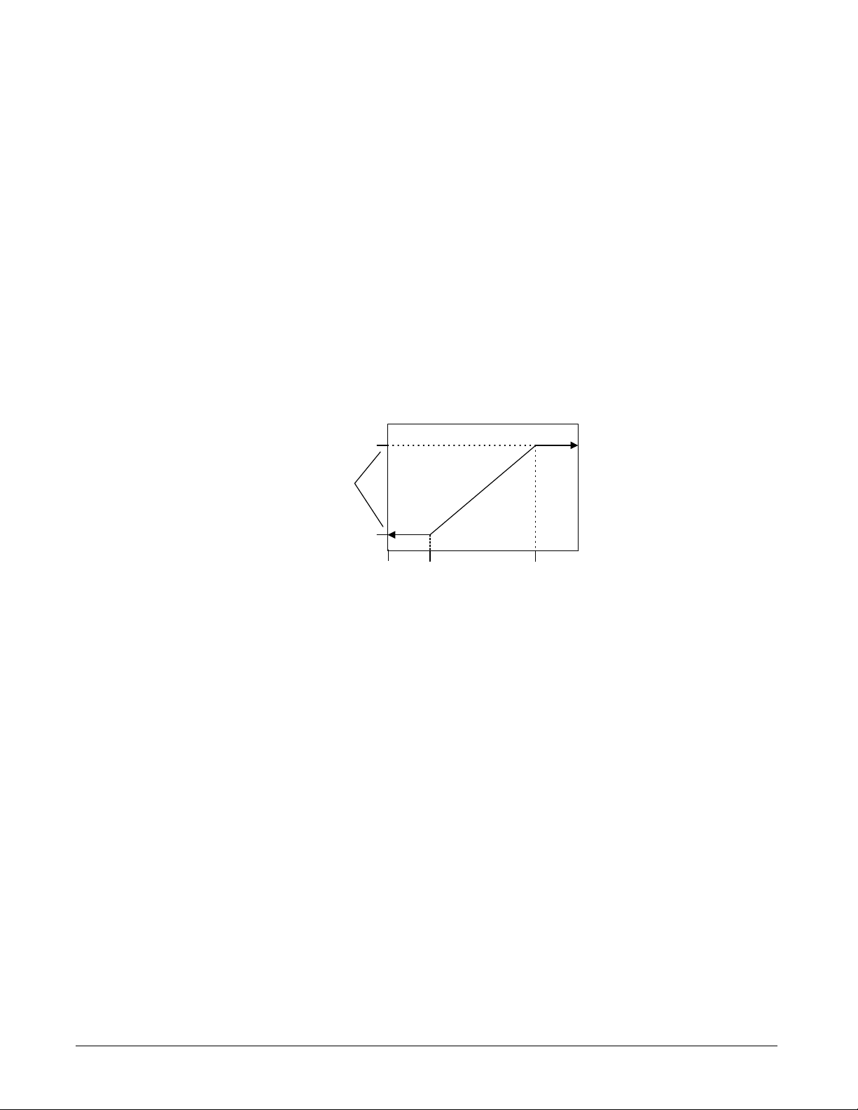
4-20 mA External Signal Reset
The Active Leaving Water variable is adjusted by the 4 to 20 mA reset analog input.
Parameters used:
1. Cool LWT setpoint
2. Max Reset setpoint
3. LWT Reset signal
Reset is 0 if the reset signal is less than or equal to 4 mA. Reset is equal to the Max Reset
Delta T setpoint if the reset signal equals or exceeds 20 mA. The amount of reset will
vary linearly between these extremes if the reset signal is between 4 mA and 20 mA. An
example of the operation of 4-20 reset in Cool mode follows.
4-20 mA Reset - Cool Mode
(54)
Active
LWT
(oF)
Max Reset
(10)
Cool LWT Set
Point (44)
4
0
Reset Signal (mA)
20
Outside Air Temperature (OAT) Reset
The Active Leaving Water variable is reset based on the outdoor ambient temperature.
Parameters used:
1. Cool LWT setpoint
2. Max Reset setpoint
3. Start Reset OAT setpoint
4. Max Reset OAT setpoint
5. OAT
Reset is 0 if the outdoor ambient temperature is greater than Start Reset OAT setpoint.
From Start Reset OAT setpoint down to Max Reset OAT the reset varies linearly from no
reset to the max reset at Max Reset OAT setpoint. At ambient temperatures less than
Max Reset OAT setpoint, reset is equal to the Max Reset setpoint.
OM 1051-2 27
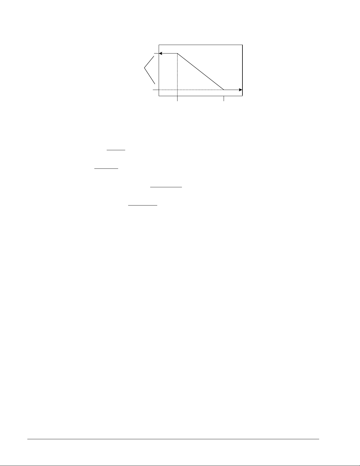
Cool LWT+Max Reset
(54)
OAT Reset
Active
LWT
(oF)
Max Reset
(10)
Cool LWT Set-Point
(44)
60
OAT (oF)
75
Unit Capacity Control
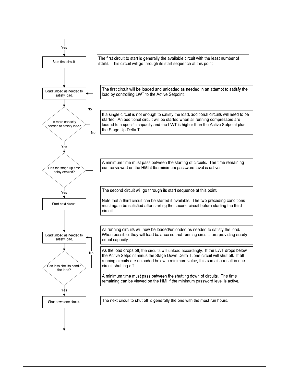
Compressor Staging in Cool Mode
The first compressor on the unit is started when evaporator LWT is higher than the target
plus the Startup Delta T setpoint.
An additional compressor is started when Evaporator LWT is higher than the target plus
the Stage Up Delta T setpoint.
When multiple compressors are running, one will shut down if evaporator LWT is lower
than the target minus the Stage Down Delta T setpoint.
All running compressors will shut down when the evaporator LWT is lower than the
target minus the Shut Down Delta T setpoint.
Stage Up Delay
A minimum amount of time will pass between compressors starting, which is defined by
the Stage Up Delay setpoint. This delay will only apply when at least one compressor is
running. If the first compressor starts and quickly fails on an alarm, another compressor
will start without this minimum time passing.
Required Load for Stage Up
An additional compressor will not be started until all running compressors are at a
capacity higher than the Load Stage Up setpoint, or running in a limited state.
Light Load Stage Down
When multiple compressors are running, one will shut down if all running compressors
are at a capacity lower than the Load Stage Down setpoint and the evaporator LWT is less
than the target plus the Stage Up Delta T setpoint. A minimum amount of time will pass
between compressors stopping as a result of this logic, which is defined by the Stage
Down Delay setpoint.
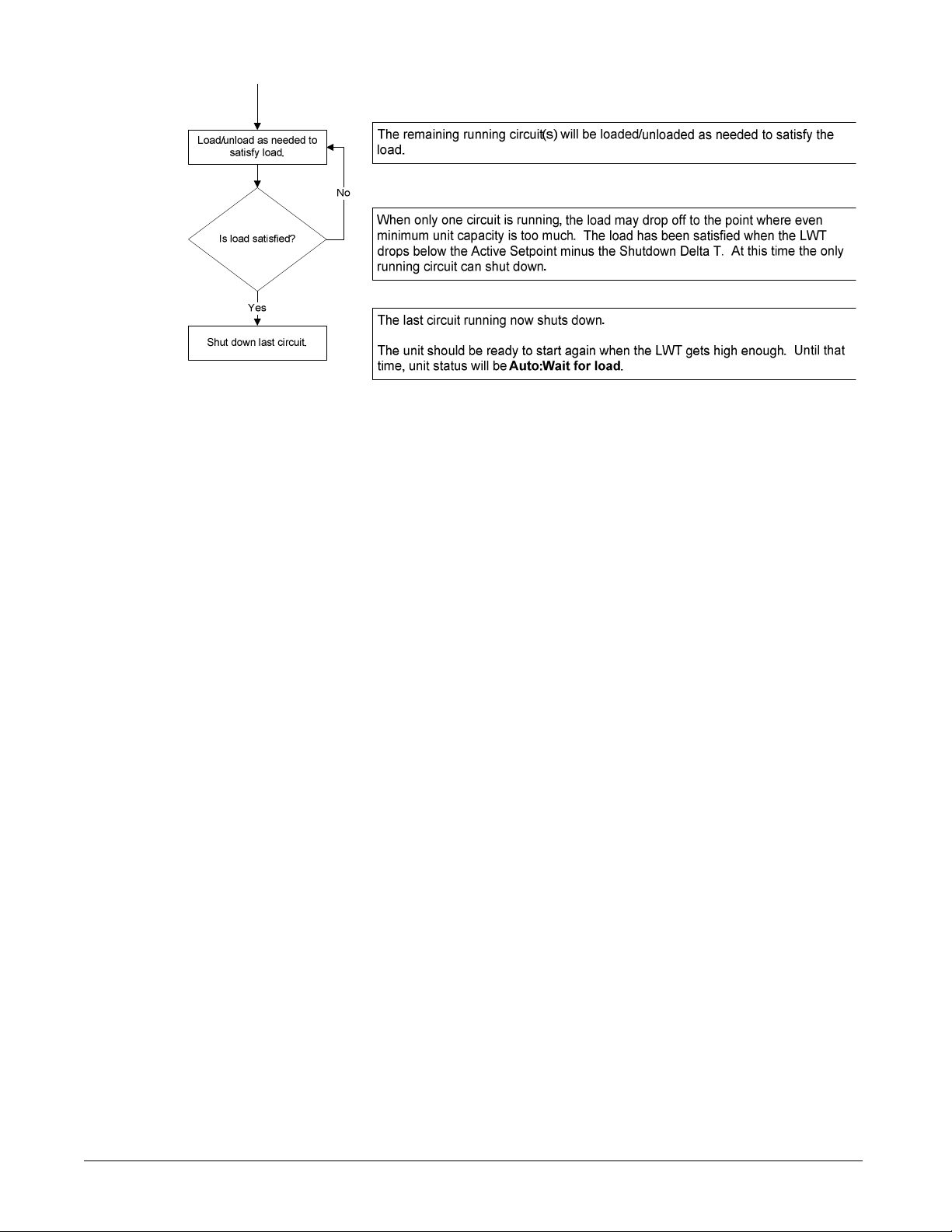
Light Load Shut Down
When the following conditions are met, the last compressor running on the chiller will be
shut down:
• One compressor running
• Evaporator Delta T < 0.25*(Nominal Evap Delta T Setpoint/Number of Circuit
Setpoint) for longer than five minutes
• Variable Evap Flow Setpoint = No
Maximum Circuits Running
If the number of compressors running is equal to the Max Circuits Running setpoint, no
additional compressors will be started.
When multiple compressors are running, one will shut down if the number of
compressors running is more than the Max Circuits Running setpoint.
28 OM 1051-2

Staging Sequence
This section defines which compressor is the next one to start or stop. In general,
compressors with fewer starts will normally start first, and compressors with more run
hours will normally stop first. Compressor staging sequence can also be determined by an
operator defined sequence via setpoints.
Next To Start
The next compressor to start must meet the following requirements:
Lowest sequence number of those compressors available to start
• -if sequence numbers are equal, it must have the least starts
• -if starts are equal, it must have least run hours
• -if run hours are equal, it must be the lowest numbered compressor
Next To Stop
The next compressor to shut down must meet the following requirements:
Lowest sequence number of the compressors that are running
• -if sequence numbers are equal, it must have the most run hours
• -if run hours are equal, it must have the fewest starts
• -if starts are equal, it must be the lowest numbered compressor
Compressor Capacity Control in Cool Mode
In Cool mode, evaporator LWT is controlled to a temperature within a calculated
variation range of the target under constant flow conditions by controlling capacity of the
individual compressors. The allowed variation is plus or minus 4% of nominal
evaporator delta t.
Compressors are loaded with a fixed step scheme. The rate of capacity adjustment is
determined by the time between capacity changes. The farther away from the target, the
faster compressors will be loaded or unloaded.
The logic projects ahead to avoid overshoot, such that the overshoot does not cause the
unit to shut off due to evaporator LWT dropping below the target minus the Shutdown
Delta T setpoint while there is still a load on the loop at least equal to the minimum unit
capacity.
Capacity of the compressors is controlled so that when possible their capacities are
balanced.
Circuits that are running in manual capacity control or running with active capacity
limiting events are not considered in the capacity control logic.
The compressor capacities are adjusted one at a time while maintaining a capacity
imbalance that does not exceed 12.5%.
Load/Unload Sequence
This section defines which compressor is the next one to load or unload.
Next To Load
The next compressor to load meets the following requirements:
Lowest capacity of the running compressors that can load up
• if capacities are equal, it must have the lowest sequence number of the compressors
that are running
• if the sequence numbers are equal, it must have the least starts
• if run starts are equal, it must have the least hours
• if starts hours are equal, it must be the lowest numbered compressor
OM 1051-2 29

Next To Unload
The next compressor to unload must meet the following requirements:
Highest capacity of the running compressors
• if capacities are equal, it must have the lowest sequence number of the compressors
that are running
• if sequence numbers are equal, it must have the most run hours
• if run hours are equal, it must have the least starts
• if starts are equal, it must be the lowest numbered compressor
Compressor Capacity Control in Ice Mode
In Ice mode, running compressors are loaded up simultaneously at the maximum possible
rate that allows for stable operation of the individual circuits.
Unit Capacity Overrides
Unit capacity limits are used to limit total unit capacity in Cool mode only. Multiple
limits may be active at any time, and the lowest limit is always used in the unit capacity
control.
Soft load, demand limit, and network limit use a deadband around the actual limit value,
such that unit capacity increase is not allowed within this deadband. If unit capacity is
above the deadband, capacity is decreased until it is back within the deadband.
• For 2 circuit units, the deadband is 7%.
• For 3 circuit units, the deadband is 5%.
Soft Load
Soft Loading is a configurable function used to ramp up the unit capacity over a given
time. The setpoint that control this function are:
• Soft Load – (ON/OFF)
• Begin Capacity Limit – (Unit %)
• Soft Load Ramp – (seconds)
The Soft Load Unit Limit increases linearly from the Begin Capacity Limit set-point to
100% over the amount of time specified by the Soft Load Ramp set-point. If the option is
turned off, the soft load limit is set to 100%.
Demand Limit
The maximum unit capacity can be limited by a 4 to 20 mA signal on the Demand Limit
analog input, usually from a BAS, on the unit controller. This function is only enabled if
the Demand Limit setpoint is set to ON and the control is in the COOL mode.
As the signal varies from 4 mA up to 20 mA, the maximum unit capacity changes from
100% to 0%. The unit capacity shall be adjusted as needed to meet this limit, except that
the last running compressor cannot be turned off to meet a limit lower than the minimum
unit capacity.
Network Limit
The maximum unit capacity can be limited by a network signal. This function is only
enabled if the unit control source is set to network. The signal will be received through
the BAS interface on the unit controller.
As the signal varies from 0% up to 100%, the maximum unit capacity changes from 0%
to 100%. The unit capacity is adjusted as needed to meet this limit, except that the last
running compressor cannot be turned off to meet a limit lower than the minimum unit
capacity.
30 OM 1051-2
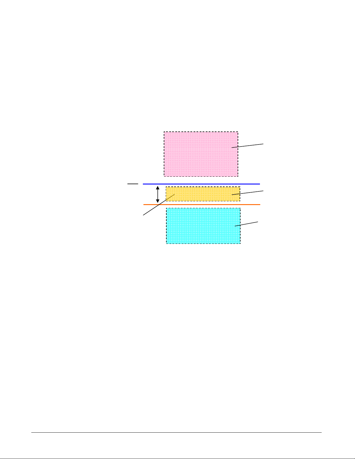
Current Limit
unload area
Unload area
Current Limit control is enabled only when the current limit enable input is ON.
Unit current is calculated based on the 4-20 mA input that receives a signal from an
external device. The current at 4 mA is assumed to be 0, and the current at 20 mA is
defined by a setpoint. As the signal varies from 4 to 20 mA, the calculated unit current
varies linearly from 0 amps to the amp value defined by the setpoint.
The current limit uses a deadband centered around the actual limit value, such that unit
capacity increase is not allowed when current is within this deadband. If unit current is
above the deadband, capacity is decreased until it is back within the deadband. The
current limit deadband is 5% of the current limit.
Figure 9, Current Limit Operation
Current Limit
Hold area
5% of HMI setpoint
Free to load or
Maximum LWT Pulldown Rate
The maximum rate at which the leaving water temperature can drop is limited by the
Maximum Rate setpoint, only when the LWT is less than 59°F (15°C).
If the pulldown rate is higher than the Maximum Pulldown Rate set point minus 0.1°C,
the unit capacity should not be increased.
If the pulldown rate is higher than the Maximum Pulldown Rate set point plus 0.1°C, the
unit capacity should be reduced until the rate is less than that value.
High Water Temperature Capacity Limit
If the evaporator LWT exceeds 77°F (25°C), compressor load will be limited to a
maximum of 80%. Compressors will unload to 80% or less if running at greater than
80% load when the LWT exceeds the limit. This feature is to keep the circuit running
within the capacity of the condenser coil.
Pumpdown
The circuit state should be Pump down when any of the following conditions are true.
1. Normal shut down alarm exists in Run state.
2. LWT error is less than Shut down delta T in case of 1 circuit running
3. LWT error is less than Stage down delta T in case of 2 circuit running
4. Unit state is Pumpdown
5. Circuit switch is Off
OM 1051-2 31

Cycle Timer
A minimum time between starts of the compressor and a minimum time between shutdown and
start of the compressor shall be enforced.
The time values are set by global circuit setpoints. These cycle timers shall be enforced even
through cycling of power to the chiller.
These timers may be cleared via a setting on the HMI.
Start-to-start time is the time period from when a compressor starts until it starts again.
Stop-to-start is the time period from when a compressor stops until it restarts.
Table 6, Cycle Time Settings
Function Default
Start - Start time 20 min 15 min 60 min
Stop - Start time 5 min 3 min 20 min
minimum maximum
Range
Circuit Start-up Delta T, Shut-down Delta T
To avoid excessive ON/OFF compressor cycling when the capacity required is very low.
The first compressor on the unit will be started when evaporator LWT is higher than the LWT
target plus the Startup Delta T setpoint.
An additional compressor will be started when evaporator LWT is higher than the target plus
the Stage Up Delta T setpoint.
When multiple compressors are running, one will shut down if Evaporator LWT is lower than
the target minus the Stage Down Delta T setpoint.
All running compressors will shut down when the evaporator LWT is lower than the target
minus the Shut Down Delta T setpoint.
Circuit Pulldown Rate
The pulldown rate is established to control the capacity of the compressor so that it does not
pull down the chilled water temperature too fast and overshoot the LWT target and to avoid
excessive compressor cycling.
The maximum rate at which the leaving water temperature can drop is limited by the
Maximum Rate setpoint, only when the LWT is less than 15°C (59°F).
If the pulldown rate is higher than the Maximum Pulldown Rate setpoint minus 0.1°C, the unit
capacity will not be increased.
If the pulldown rate is higher than the Maximum Pulldown Rate setpoint plus 0.1°C, the unit
capacity will be reduced until the rate is less than that value.
Non-VFD models
EWT slope is calculated such that the slope represents the estimated change in EWT over a
time frame of one minute. This slope is used to determine the compressor capacity
VFD models
Compressor capacity is controlled by compressor speed and a sophisticated algorithm is used
to determine rate.
32 OM 1051-2

Unit Capacity Control
Non-VFD models
An estimate of total unit capacity is needed for applying unit capacity limits. Unit
capacity will be based on the estimated circuit capacities.
The unit capacity is the average of the estimated circuit capacities.
In Cool mode, evaporator LWT is controlled to a temperature within a calculated
variation range of the target under constant flow conditions by controlling capacity of the
individual compressors. The allowed variation is plus or minus 4% of nominal
evaporator delta t.
Compressors are loaded with a fixed step scheme. The rate of capacity adjustment is
determined by the time between capacity changes. The farther away from the target, the
faster compressors will be loaded or unloaded.
The logic will project ahead to avoid overshoot, such that the overshoot does not cause
the unit to shut off due to evaporator LWT dropping below the target minus the Shutdown
Delta T setpoint while there is still a load on the loop at least equal to the minimum unit
capacity.
Capacity of the compressors is controlled so that when possible their capacities are
balanced.
Circuits that are running in manual capacity control or running with active capacity
limiting events are not considered in the capacity control logic.
The compressor capacities are adjusted one at a time while maintaining a capacity
imbalance that does not exceed 12.5%.
VFD models
The purpose of this logic is as follows.
• To avoid load/unload hunting.
• To reach LWT target at appropriate speed.
• To avoid unnecessary shut downs.
• To keep LWT within +/-0.1C of LWT target as possible.
Compressor capacity is controlled by compressor speed and a sophisticated algorithm is
used to determine the rate considering the various parameters affecting capacity.
OM 1051-2 33

Circuit Functions
Calculations
Refrigerant Saturated Temperature
Refrigerant saturated temperature is calculated from the pressure sensor readings for each
circuit. A function provides the converted value of temperature to match values published
data for R134a:
-within 0.18°F (0.1°C) for pressure inputs from 0 to 300 psi (0 to 2070kPa)
-within 0.36°F (0.2°C) for pressure inputs from -11.6 to 0 psi (80 kPa to 0 kPa)
Evaporator Approach
The evaporator approach is calculated for each circuit. The equation is as follows:
Evaporator Approach = LWT – Evaporator Saturated Temperature
Condenser Approach
The condenser approach is calculated for each circuit. The equation is as follows:
Condenser Approach = Condenser Saturated Temperature - OAT
Suction Superheat
Suction superheat is calculated for each circuit using the following equation:
Suction superheat = Suction Temperature – Evaporator Saturated Temperature
Discharge Superheat
Discharge superheat is calculated for each circuit using the following equation:
Discharge superheat = Discharge Temperature – Condenser Saturated
Temperature
Oil Differential Pressure
Oil Differential Pressure is calculated for each circuit with this equation:
Oil Differential Pressure = Condenser Pressure - Oil Pressure
Maximum Saturated Condenser Temperature
The maximum saturated condenser temperature calculation is modeled after the
compressor operational envelope.
If Sat Evap Temp < 32°F (0°C) then
Max Sat Cond Temp = 1.596(Sat Evap Temp) +155°F (68.3°C)
Otherwise, Max Sat Cond Temp = 155°F (68.3°C)
High Saturated Condenser – Hold Value
High Cond Hold Value = Max Saturated Condenser Value – 5°F (2.78°C)
High Saturated Condenser – Unload Value
High Cond Unload Value = Max Saturated Condenser Value – 3°F (1.67°C)
Condenser Saturated Temperature Target
The saturated condenser temperature target is calculated by using the following equation:
Sat condenser temp target raw = 0.8332(evaporator sat temp) + 95.0°F (35.0 °C)
This value is then limited to a range defined by the Condenser Saturated Temperature
Target min and max setpoint. These setpoint simply cut off the value to a working range,
and this range can be limited to a single value if the two setpoint are set to the same value.
34 OM 1051-2

Circuit Control Logic
Circuit Availability
A circuit is available to start if the following conditions are true:
• Circuit switch is closed
• No circuit alarms are active
• Circuit Mode setpoint is set to Enable
• BAS Circuit Mode setpoint is set to Auto
• No cycle timers are active
• Discharge Temperature is at least 9°F (5°C) higher than Oil Saturated Temperature
Starting
The circuit will start if all these conditions are true:
• Adequate pressure in the evaporator and condenser (see No Pressure At Start Alarm)
• Circuit Switch is closed
• Circuit Mode setpoint is set to Enable
• BAS Circuit Mode setpoint is set to Auto
• No cycle timers are active
• No alarms are active
• Staging logic requires this circuit to start
• Unit state is Auto
• Evaporator pump state is Run
Circuit Startup Logic
Circuit startup is the time period following the starting of the compressor on a circuit.
During the startup, the low evaporator pressure alarm logic is ignored. When the
compressor has been running at least 20 seconds and the evaporator pressure rises above
the low evaporator pressure unload setpoint, the startup is complete.
If the pressure does not rise above the unload setpoint and the circuit has been running
longer than the Startup Time setpoint, then the circuit is turned off and an alarm triggered.
If the evaporator pressure drops below the absolute low pressure limit then the circuit is
turned off and the same alarm triggered.
Low OAT Restart Logic
Low OAT restart logic allows multiple start attempts in low ambient conditions. If the
condenser saturated temperature is less than 60°F (14.6°C) when the compressor starts,
the startup is considered to be a ‘low OAT start’. If a low OAT start is not successful the
circuit is shut down, but no alarm is triggered for the first two attempts of the day. If a
third low OAT start attempt fails, then the circuit is shut down and the Low OAT Restart
Alarm is triggered.
The restart counter is reset when a startup is successful or the Low OAT Restart alarm is
triggered.
Stopping
Normal Shutdown
A normal shutdown requires the circuit to pumpdown before the compressor is turned off.
This is done by closing the EXV, and closing the liquid line solenoid (if present) while
the compressor is running.
OM 1051-2 35

The circuit will do a normal shutdown (pumpdown) if any of the following are true:
• Staging logic requires this circuit to stop
• Unit State is Pumpdown
• A pumpdown alarm occurs on the circuit
• Circuit switch is open
• Circuit Mode setpoint is set to Disable
• BAS Circuit Mode setpoint is set to Off
The normal shutdown is complete when any of the following are true:
• Evaporator Pressure is less than the Pumpdown Pressure setpoint
• Service Pumpdown setpoint is set to Yes and Evaporator Pressure is less than
5 psi (34.5 kPa)
• Circuit has been pumping down for longer than the Pumpdown Time Limit setpoint
Rapid Shutdown
A rapid shutdown requires the compressor to stop and the circuit to go to the Off state
immediately.
The circuit will do a rapid shutdown if either of these conditions occurs at any time:
• Unit State is Off
• A rapid stop alarm occurs on the circuit
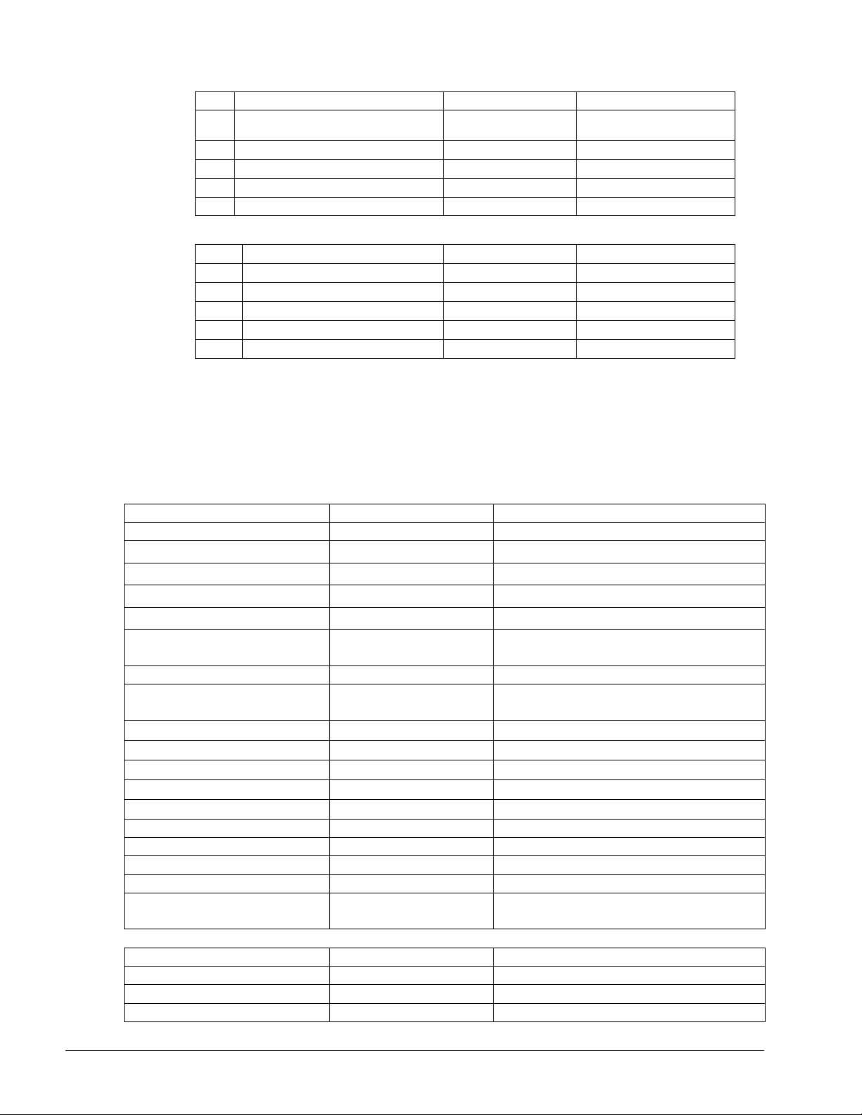
Circuit Status
The displayed circuit status is determined by the conditions in the following table:
Table 7, Circuit Status
Enum Status Conditions
0 Off:Ready Circuit is ready to start when needed.
1 Off:Stage Up Delay Circuit is off and cannot start due to stage up delay.
2 Off:Cycle Timer Circuit is off and cannot start due to active cycle timer.
3 Off:BAS Disable Circuit is off and cannot start due to BAS command.
4 Off:Keypad Disable Circuit is off and cannot start due to keypad disable.
5 Off:Circuit Switch Circuit is off and circuit switch is off.
6 Off:Refr In Oil Sump
7 Off:Alarm Circuit is off and cannot start due to active circuit alarm.
8 Off:Test Mode Circuit is in test mode.
9 EXV Preopen Circuit is in preopen state.
10 Run:Pumpdown Circuit is in pumpdown state.
11 Run:Normal Circuit is in run state and running normally.
12 Run:Disch SH Low
13 Run:Evap Press Low
14 Run:Cond Press High
15 Run: High LWT Limit
16 Run: High VFD Amps
17 Off: Max Comp Starts
Circuit is off and Discharge Temperature – Oil
Saturated Temperature at gas pressure <= 5°C
Circuit is running and cannot load due to low discharge
superheat.
Circuit is running and cannot load due to low evaporator
pressure.
Circuit is running and cannot load due to high
condenser pressure.
Circuit is running and cannot load due to high
evaporator leaving water temperature.
Circuit is running and cannot load due to high
compressor VFD current output.
Circuit is off and cannot start due to four starts in the
last hour. Remaining time displayed.
36 OM 1051-2

Compressor Control
The compressor runs only when the circuit is in a start, run or pumpdown state. The
compressor will not be running any time the circuit is off or during preopening the EXV.
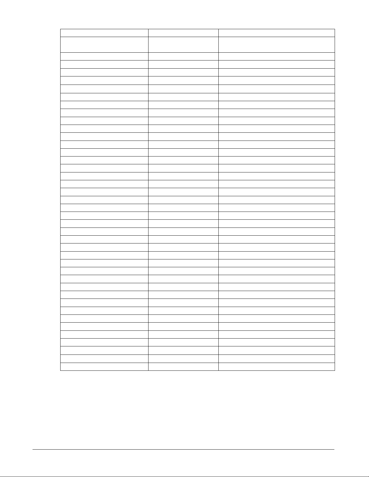
Compressor State
The compressor will always be in one of the following states
Name Meaning
Off Comp off.
Start Comp in Start control.
Run Comp in automatic or manual capacity control.
Pump down Comp in shut down control.
Compressor Off
The control state will be Off when the circuit state is Off.
Compressor Start
The purpose of this logic is:
• To avoid the suction pressure dropping too much at start.
• To prohibit loading until circuit state is stable.
The control state should be Start up when the circuit state is Start. Start up is controlled
by logic considering EXV preopen time, compressor start time, suction superheat and
other parameters.
Capacity Control, Non-Compressor VFD Models
After starting, the compressor capacity target should be the minimum of 10%, and no
attempt to increase compressor capacity should be made until the compressor has been
running at least three minutes and the minimum discharge superheat has been established
for at least 30 seconds. After this condition is met, the compressor capacity target shall
move via steps to a minimum running capacity even if unit capacity control commands do
not require the compressor to load up. This minimum running capacity target is 26% for
European chillers and 25% for US chillers.
Once the compressor has been loaded to the minimum running capacity target, the
capacity target shall always be at least equal to this value while the compressor is
running.
Changes to the capacity target shall be performed as needed to meet unit capacity
requirements based on load and unload commands (see unit capacity control section). For
European chillers, the standard capacity target step is 4%, and for US chillers it is 5%.
A minimum time of 20 seconds should pass between capacity changes other than the
capacity transitions from 50% to 60% or from 60% to 50%. For those capacity
transitions, a minimum time of 30 seconds should pass before capacity is changed again.
OM 1051-2 37

Capacity Control, Compressor VFD Models
The control state is Capacity control when the circuit state is Run.
The purpose of this logic is as follows.
• To avoid the unnecessary shut down due to excessive loading.
• In the high LWT area, the loading should be faster.
• When the DSH is low, it could be an abnormal situation, so the loading should be limited.
Load control
Comp will Load when all the following is true.
• LWT error > Keep dead band
• EWT Pd Rate < EWT Pd Rate limit
•
DSH > 12C for 30sec at least
Unload control
Compressor will Unload when any of the following conditions are true
• LWT error < minus Keep dead band
• HP > HP_unload
• LP < LP_unload
• EWT Pd Rate > EWT Pd Rate for unload
•
Inverter over current unload
Manual capacity control
This function is only for use by authorized service personnel and a special password is
requires for access.
Condenser Fan Control
The compressor must be running in order to stage fans on. All running fans will turn off
when compressor goes to the Off state.
Saturated Condenser Temperature Target
The saturated condenser temperature target is calculated by first using the following
equation:
Sat condenser temp target raw = 0.8332(suction sat temp) + 63.6°F (35.0°C)
This value is then limited to a range defined by the Condenser Saturated Temperature
Target min and max setpoint. These setpoint simply cut off the value to a working range,
and this range can be limited to a single value if the two setpoint are set to the same value.
Fan Control without VFD
The fan stage is adjusted in steps of 1 fan. Fan staging will accommodate anywhere from
5 to 12 fans per circuit according to the following table:
Output Number
1 2 3 4 5 6
# of fans
5
6
7
8
9
10
11
12
38 OM 1051-2

Figure 10, Fan Staging Up and Down
If this error accumulation is greater than 5.0 deg F (2.8 deg C), then fan stage down.
If this error accumulation is greater than 19.8 deg F (11 deg C) then stage up.
(Target) + (fan stage up dead band)
Target discharge saturated temp
(Target) - (fan stage down dead band)
Referring to Figure 10, a fan will run normally when the saturated discharge temperature
(equivalent to discharge pressure) is between the Target Temperature plus the stage up
deadband and minus the stage down deadband.
If the saturated temperature exceeds the stage up or stage down setting, an error
accumulation is calculated. The error accumulation takes into account how great the error
is and its duration. Thusly, a small error can exist for a relatively long time and a large
error for a relatively short time before a fan is staged on or off.
If the saturated temperature returns to within the deadband area, the error accumulation is
cleared.
Staging Up
Six stage-up deadbands are used. Stages one through five use their respective dead bands.
Stages six through twelve all use the sixth stage up dead band.
When the saturated condenser temperature is above the Target + the active deadband, a
Stage Up error is accumulated.
Stage Up Error Step = Saturated Cond. temperature – (Target + Stage-Up deadband)
The Stage Up Error Step is added to Stage Up Accumulator once every 5 seconds, only if
the Saturated Condenser Refrigerant Temperature is not falling. When Stage Up Error
Accumulator is greater than 19.8°F (11°C) another stage is added.
If the circuit is configured to have a VFD on the first fan, then the first fan will turn on
when condenser temperature is above the target.
When a stage up occurs or the saturated condenser temperature falls back within the Stage
Up dead band the Stage Up Accumulator is reset to zero.
Staging Down
Five stage down dead bands are used. Stages two through five use their respective dead
bands. Stages six through twelve all use the stage six dead band.
OM 1051-2 39

When the saturated condenser refrigerant temperature is below the Target – the active
deadband, a Stage Down error is accumulated.
Stage Down Error Step = (Target - Stage Down dead band) - Saturated Condenser
Refrigerant temperature
The Stage Down Error Step is added to Stage Down Accumulator once every 5-second
Stage Down Error Delay seconds. When the Stage Down Error Accumulator is greater
than 37°F (2.8°C) another stage of condenser fans is removed.
When one fan is running, a fixed point is used in place of a deadband. When the
Saturated Condenser temperature drops below 70°F (21.1°C), stage down error is
accumulated.
Fan Control with VFD
Condenser pressure trim control is accomplished using an optional VFD on the first fan.
This VFD control varies the fan speed to drive the saturated condenser temperature to a
target value. The target value is normally the same as the saturated condenser
temperature target.
VFD State
The VFD speed signal is always 0 when the fan stage is 0.
When the fan stage is greater than 0, the VFD speed signal is enabled and controls the
speed as needed.
Stage Up Compensation
In order to create a smoother transition when another fan is staged on, the VFD
compensates by slowing down initially.
This is accomplished by adding the new fan stage up deadband to the VFD target. The
higher target causes the VFD logic to decrease fan speed.
Then, every 2 seconds, 0.1°C is subtracted from the VFD target until it is equal to the
saturated condenser temperature target set point.
This will allow the VFD to slowly bring the saturated condenser temperature back down.
EXV Control
The EXV is moved at a rate of 150 steps per second, with a total range of 3810 steps.
Positioning is determined as described in the following sections, with adjustments made
in increments of 0.1% of the total range.
Closed Position
When the EXV enters the closed state, it should be reinitialized to maintain accurate
positioning.
If the unit is configured for use without liquid line solenoid valves, the EXV position is
0% any time the EXV is in a closed state.
If the unit is configured for use with liquid line solenoid valves, the EXV position will be
0% when the EXV initially enters the closed state, while it is reinitializing to the zero
position. After the EXV position command has been 0% for a minute, the EXV will be
moved to 5% (to prevent excessive pressure buildup between EXV and liquid line
solenoid valve).
Preopen Operation
Preopen operation will vary depending on the unit configuration. The unit will be
configured for use with or without liquid line solenoid valves via a setpoint.
40 OM 1051-2

Without Liquid Line Solenoid Valves
The EXV control will open the EXV to 5% for 5 seconds before the compressor is started.
With Liquid Line Solenoid Valves
If evaporator pressure is less than condenser pressure when a circuit start is required, the
EXV control will preopen the EXV to 50% for 15 seconds. Otherwise, the preopen time
will be 0 (position is already 5%).
Pressure Control Operation
In pressure control, the EXV is positioned to control the evaporator pressure. The
pressure target varies based on evaporator LWT and discharge superheat values.
The base target is limited to a range from the low pressure inhibit setpoint plus
2 psi (14 kPa), up to 50.7 psi (350 kPa).
The pressure control target may be adjusted if the discharge superheat is not within an
acceptable range. If the superheat is less than 21.6°F (12°C), the pressure target will be
reduced. If the superheat is more than 39.6°F (22°C), the pressure target will be
increased. The adjusted target is limited to a range from the low pressure inhibit setpoint
plus 2 psi (14 kPa), up to 50.7 psi (350 kPa).
When the EXV transitions from superheat control to pressure control, the target will start
at the current evaporator pressure value. The pressure target will then be decreased until
reaching the normal calculated target, at a rate of 0.43 psi (3 kPa) per second. If the
pressure at transition is less than the calculated target, then pressure control will start
immediately with the calculated target.
When the EXV transition from preopen to pressure control, the target starts at the
minimum and is held there for three minutes. After that time, the target is increased until
it meets the calculated target, at a rate of 0.43 psi (3 kPa) per second.
The EXV should control the evaporator pressure to within 1.0 psi (7 kPa) of the target
during stable operating conditions (stable water loop, static compressor capacity, and
stable condensing temperature).
Superheat Control Operation
In superheat control, the EXV is positioned to control suction superheat. The superheat
target varies linearly from 5 to 9.9 °F (2.8 to 5.5 °C) as discharge superheat changes from
30.6 to 21.6 °F (17 to 12 °C). This target is constantly updated, and averaged over a 10
second period.
When the EXV transitions to the superheat control state, the target will start at the current
suction superheat value. This target will then be decreased 0.18°F (0.1°C) every five
seconds until reaching the normal calculated target.
The EXV should control the suction superheat to within 1.5°F (0.8°C) of the target during
stable operating conditions (stable water loop, static compressor capacity, and stable
condensing temperature).
Control State Transitions
When the circuit is required to start, the EXV will go into the Preopen control state. After
being in this state for the time period required, the EXV can transition to Pressure
Control. The compressor will start at the same time that this occurs.
While the circuit is in a run state, the EXV will always be in either Pressure Control or
Superheat Control.
The transition from Pressure Control to Superheat Control requires all of the following:
• Evap LWT <= 59.9°F (15.5°C)
OM 1051-2 41

• Suction Superheat >= suction superheat target
• EXV control state has been in pressure control and discharge superheat >= 12°C
(21.6°F) for at least 3 minute
• Low Evap Pressure Unload alarm is not active
The transition from Superheat Control to Pressure Control will occur if any of the
following conditions exist:
• Discharge Superheat < 12°C (21.6°F)
• Evap LWT > 17°C (62.6°F)
Any time the circuit is in the Off state or Pumpdown state, the EXV should be in the
closed position.
Response to Compressor Capacity Change
The logic will consider transition from 50% to 60% and from 60% to 50% as special
conditions. During this time, the EXV will operate in a way that prevents over-feeding or
under-feeding the evaporator such that adequate superheats are maintained following the
transition, no liquid ingestion by the compressor occurs, and no evaporator pressure dip
causes low pressure alarms.
Minimum Operating Position
Whenever the compressor is running and the circuit is not pumping down, the EXV
position is limited to a minimum of 5%.
Auto Control
When the EXV is in auto control and the EXV control state is either pressure control or
superheat control, the position will be adjusted using a PID function. This function
should control the pressure or superheat as outlined in the preceding sections.
The compressor size setting will adjust the proportional factor of the PID when in
superheat control to allow for stable control of the superheat.
Manual Control
The EXV position can be set manually. Manual control can only be selected when the
EXV state is Pressure or Superheat control. At any other time, the EXV control setpoint
is forced to auto.
When EXV control is set to manual, the EXV position is equal to the manual EXV
position setting. If set to manual when the circuit state transitions from run to another
state, the control setting is automatically set back to auto. If EXV control is changed
from manual back to auto while the circuit state remains run, the EXV state will go back
to the normal operations if possible or to pressure control to limit maximum operating
pressure.
Economizer Control
Non-VFD: The circuit economizer will be activated when the circuit is in a run state and
the capacity exceeds 95%. It will turn back off when either the load drops below 80% or
the circuit is no longer in a run state.
Compressor VFD: The economizer is on any time the circuit is running.
Liquid Injection
Liquid injection will be activated when the circuit is in a run state and the discharge
temperature rises above the Liquid Injection Activation setpoint.
Liquid injection will be turned off when the discharge temperature decreases below the
activation setpoint by a differential of 27°F (15°C).
42 OM 1051-2

Liquid Line Solenoid Valve
The liquid line solenoid valve output will be on any time the circuit is in the Start or Run
state. It will be off when the circuit is in the Off, Preopen, or Pumpdown states.
Capacity Overrides – Limits of Operation
The following conditions will override automatic capacity control as described. These
overrides keep the circuit from entering a condition in which it is not designed to run.
Low Evaporator Pressure
This limit is to be applied only when the chiller is operating in COOL mode.
If the Low Evaporator Pressure Hold alarm is triggered, the compressor will not be
allowed to increase in capacity.
If the Low Evaporator Pressure Unload alarm is triggered, the compressor will begin
reducing capacity.
The compressor will not be allowed to increase in capacity until the Low Evaporator
Pressure Hold alarm has cleared.
See the Circuit Alarms section for details on triggering, reset, and unloading action.
High Condenser Pressure
This limit is to be applied only when the chiller is operating in COOL mode.
If the High Condenser Pressure Hold alarm is triggered, the compressor will not be
allowed to increase capacity.
If the High Condenser Pressure Unload alarm is triggered, the compressor will begin
reducing capacity.
The compressor will not be allowed to increase in capacity until the High Condenser
Pressure Hold alarm has cleared.
See the Circuit Alarm section for details on triggering, reset, and unloading action.
High Water Temperature Capacity Limit
If the evaporator LWT is 25°C (77°F) or higher, compressor capacity will be limited to a
maximum of 80%. Compressors should unload to 80% or less if running at greater than
80% capacity when the LWT exceeds 25°C (77°F).
OM 1051-2 43

Alarms and Events
Situations may arise that require some action from the chiller, or that should be logged for
future reference. Alarms are classified in the following sections per the Global Chiller
Protocol Standard using the Fault/Problem/Warning scheme.
When any Unit Fault Alarm is active, the alarm digital output will be turned on. If no
Unit Fault Alarm is active, but any Circuit Fault Alarm is active, the alarm digital output
will alternate five seconds on and five seconds off constantly. In addition, if a Circuit
Fault Alarm is active, the circuit alarm output for that circuit will be turned on.
Signaling Alarms
The following actions will signal that an alarm has occurred:
1. The unit or a circuit will execute a rapid or pumpdown shutoff.
2. An alarm bell icon will be displayed in the upper right-hand corner of all controller
screens including the optional remote user interface panel’s screens.
3. An optional field supplied and wired remote alarm device will be activated.
Clearing Alarms/Faults
Active alarms can be cleared through the keypad/display or a BAS network. Alarms are
automatically cleared when controller power is cycled. Alarms are cleared only if the
conditions required to initiate the alarm no longer exist. All alarms and groups of alarms
can be cleared via the keypad or network via LON using nviClearAlarms and via BACnet
using the ClearAlarms object.
To use the keypad, follow the Alarm links to the Alarms screen, which will show Active
Alarms and Alarm Log. Select Active Alarm and press the wheel to view the Alarm List
(list of current active alarms). They are in order of occurrence with the most recent on
top. The second line on the screen shows Alm Cnt (number of alarms currently active)
and the status of the alarm clear function. Off indicates that the Clear function is off and
the alarm is not cleared. Press the wheel to go to the edit mode. The Alm Clr (alarm clear)
parameter will be highlighted with OFF showing. To clear all alarms, rotate the wheel to
select ON and enter it by pressing the wheel.
An active password is not necessary to clear alarms.
If the problem(s) causing the alarm have been corrected, the alarms will be cleared,
disappear from the Active Alarm list and be posted in the Alarm Log. If not corrected, the
On will immediately change back to OFF and the unit will remain in the alarm condition.
Remote Alarm Signal
The unit is configured to allow field wiring of a remote alarm device. See Figure 18 on
page 71 for field wiring information.
44 OM 1051-2

Description of Alarms
Introduction
The alarms have the following conventions:
ALARM, any condition outside of normal operation requiring some action on the
part of the control or information useful to the operator or to be logged for future
reference
WARNING, an alarm indicating a condition that is not critical to safe unit operation,
but is worthy of note and/or logging.
PROBLEM, a alarm that indicates operation off normal and requires some action by
the control such as unloading a compressor.
FAULT, an alarm with consequences serious enough to require a compressor, a
circuit, or entire unit to shutdown. The shutdown may be rapid, bypassing the
pumpdown cycle, or controlled and incorporate the pumpdown cycle.
Alarm description conventions:
• CnCmpn OffMechPressLo, the Cn is the circuit number; the Cmpn is the
compressor number.
• UnitOff EvapWaterFlow, UnitOff refers to the entire unit.
Alarm Listing
The alarms are listed alphabetically below showing their location
BadLWTResetInput, Alarm 11, page 48
BadSetptOverrideInput, Alarm 12, page 49
CnCmpnInhbtLdAmpsHi, Alarm 45, page 55
CnCmpnOffCondPressHi, Alarm 17, page 50
CnCmpnOffCondPressSen, Alarm 32, page 53
CnCmpnOffDishTempSen, Alarm 36, page 53
CnCmpnOffDischTmpHi, Alarm 20, page 50
CnCmpOffEvpPressSen, Alarm 32, page 52
CnCmpn OffLowDischSH, Alarm 39, page 53
CnCmpnOffMechPressHi, Alarm 19, page 50
CnCmpnOffMotorTempHi, Alarm 24, page 51
CnCmpnOffMtrTempSen, Alarm37, page 53
CnCmpOffNoPressAtStart, Alarm 27, page 52
CnCmpnOff NoPressChgStart, Alarm 25, page 51
CnCmpOffOilFeedSen, Alarm 34, page 53
CnCmpnOffOilPrDiffHi, Alarm 21, page 50
CnCmpnOffPrRatioLo, Alarm 18, page 50
CnCmpn OffSlidePosSen, Alarm 38, page 53
CnCmpnOffStarterFlt, Alarm 22, page 51
CnCmpnOffSuctTempSen, Alarm 35, page 53
CnCmpOffVfdCommFail, Alarm 30, page 52
CnCmpnOffVfdFault, Alarm 23, page 51
CnCmpnOffVfdTempHi, Alarm 29, page 52
CnCmpnUnloadAmpsHi, Alarm 44, page 55
OM 1051-2 45

CnFailedPumpdown, Alarm 46, page 55
CnInhibitLoadCndPrHi, Alarm 42, page 54
CnInhibitLoadEvpPrLo, Alarm 40, page 54
CnLowOATRestartFault, Alarm 26, page 51
CnLowPressureStartFail, Alarm 16, page 50
CnOffCmpCtrlComFail, Alarm 28, page 52
CnOffEXVCtrlComFail, Alarm 28, page 52
CnOffPhaseVoltage, Alarm 14, page 49
CnPwrLossRun, Alarm 47, page 55
CnUnloadEvppressLo, Alarm 41, page 54
CnUnloadCndpressHi, Alarm 43, page 54
CompOffEvapPressLo, Alarm 15, page 49
StartInhbtAmbTempLo, Alarm 13, page 49
UnitExternalEvent, Alarm 10, page 48
UnitOffAmbTempSen, Alarm 6, page 48
UnitOffEmergencyStop, Alarm 8, page 48
UnitOffEvpEntWTempSen, Alarm 5, page 48
UnitOffEvpLvgWTempSen, Alarm 4, page 47
UnitOffEvapWaterFlow, Alarm 1, page 47
UnitOffEvapWaterTmpLo, Alarm 2, page 47
UnitOffEvpWTempInvrtd, Alarm 3, page 47
UnitOffExternal Alarm, Alarm 7, page 48
UnitOffPhaseVoltage, Alarm 14, page 49
UnitPowerRestore, Alarm 9, page 48
46 OM 1051-2

Unit Faults
Alarm 1, Evaporator Flow Loss
Alarm description (as shown on screen): UnitOffEvapWaterFlow
Trigger:
1: Evaporator Pump State = Run AND Evaporator Flow Digital Input = No Flow
for time > Flow Proof Setpoint AND at least one compressor running
2: Evaporator Pump State = Start for time greater than Recirc Timeout Setpoint and
all pumps have been tried
Action Taken: Rapid stop all circuits
Reset: This alarm can be cleared manually via the unit controller keypad or BAS
command, if active via trigger condition 1:
When the alarm occurs due to this trigger, it can auto reset the first two times each
day, with the third occurrence being manual reset.
For the auto reset occurrences, the alarm will reset automatically when the
evaporator state is Run again. This means the alarm stays active while the unit waits
for flow, then it goes through the recirculation process after flow is detected. Once
the recirculation is complete, the evaporator goes to the Run state which will clear
the alarm. After three occurrences, the count of occurrences is reset and the cycle
starts over if the manual reset flow loss alarm is cleared.
If active via trigger condition 2:
If the flow loss alarm has occurred due to this trigger, it is a manual reset alarm.
Alarm 2, Evaporator Water Freeze Protect
Alarm description (as shown on screen): UnitOffEvapWaterTmpLo
Trigger: Evaporator LWT or EWT drops below evaporator freeze protect setpoint.
If the sensor fault is active for either LWT or EWT, then that sensor value cannot
trigger the alarm.
Action Taken: Rapid stop all circuits
Reset: This alarm can be cleared manually via the unit controller keypad if the
alarm trigger conditions no longer exist.
Alarm 3, Evaporator Water Temperatures Inverted
Alarm description (as shown on screen): UnitOffEvpWTempInvrtd
Trigger: Evap EWT < Evap LWT - 1 deg C AND at least one circuit is running
AND EWT sensor fault not active AND LWT sensor fault not active for 30 sec
Action Taken: Pumpdown stop on all circuits
Reset: This alarm can be cleared manually via the unit controller keypad or BAS
command.
Alarm 4, Leaving Evaporator Water Temperature Sensor Fault
Alarm description (as shown on screen): UnitOffEvpLvgWTempSen
Trigger: Sensor shorted or open
Action Taken: Rapid stop all circuits
Reset: This alarm can be cleared manually via the unit controller keypad or BAS
command if the sensor is back in range.
OM 1051-2 47

Alarm 5, Entering Evaporator Water Temperature Sensor Fault
Alarm description (as shown on screen: UnitOffEvpEntWTempSen
Trigger: Sensor shorted or open
Action Taken: Pumpdown stop of all circuits
Reset: This alarm can be cleared manually via the unit controller keypad or BAS
command if the sensor is back in range.
Alarm 6, Outdoor Air Temperature Sensor Fault
Alarm description (as shown on screen): UnitOffAmbTempSen
Trigger: Sensor shorted or open
Action Taken: Normal shutdown of all circuits
Reset: This alarm can be cleared manually via the unit controller keypad or BAS
command if the sensor is back in range.
Alarm 7, External Alarm
Alarm description (as shown on screen): UnitOffExternal Alarm
Trigger: External Alarm/Event input is open for at least 5 seconds and external fault
input is configured as an alarm
Action Taken: Rapid stop of all circuits
Reset: Auto clear when digital input is closed
Alarm 8, Emergency Stop Alarm
Alarm description (as shown on screen): UnitOffEmergencyStop
Trigger: Emergency Stop input is low
Action Taken: Rapid stop of all circuits
Reset: Auto clear when digital input is high
Unit Warnings
The following unit events are logged in the warning log with a time stamp.
Alarm 9, Unit Power Restore
Alarm description (as shown on screen): UnitPowerRestore
Trigger: Unit controller is powered up
Action Taken: none
Reset: none
Alarm 10, External Event
Alarm description (as shown on screen): UnitExternalEvent
Trigger: External Alarm/Event input is open for at least 5 seconds and external fault
is configured as an event
Action Taken: None
Reset: Auto clear when digital input is closed
Alarm 11, Bad Demand Limit Input
Alarm description (as shown on screen): BadDemandLimitInput
Trigger: Demand limit input out of range and demand limit is enabled. For this
alarm out of range is considered to be a signal less than 3mA or more than 21mA
Action Taken: None
Reset: Auto clear when demand limit disabled or demand limit input back in range
for 5 seconds
48 OM 1051-2

Alarm 12, Bad Setpoint Override Input
Alarm description (as shown on screen): BadSetptOverrideInput
Trigger: LWT reset input out of range and LWT reset = 4-20mA. For this alarm out
of range is considered to be a signal less than 3mA or more than 21mA.
Action Taken: None
Reset: Auto clear when LWT reset is not 4-20mA or LWT reset input back in range
for 5 seconds
Alarm 13, Low Ambient Lockout
Alarm description (as shown on screen): StartInhbtAmbTempLo
Trigger: The OAT drops below the low ambient lockout setpoint
Action Taken: Normal shutdown of all running circuits
Reset: The lockout clears when OAT rises to the lockout setpoint plus (4.5°F)
Circuit Faults
All circuit stop alarms require shutdown of the circuit on which they occur. Rapid stop
alarms do not do a pumpdown before shutting off. All other alarms will do a pumpdown.
When one or more circuit alarms are active and no unit alarms are active, the alarm output
will be switched on and off on 5 second intervals.
Alarm descriptions apply to all circuits, the circuit number is represented by ‘n’ in the
description.
Alarm 14, Phase Volts Loss/GFP Fault
Alarm description (as shown on screen): UnitOffPhaseVoltage or
CnOff PhaseVoltage
Trigger: PVM input is low and PVM setpoint = Multi Point
Action Taken: Rapid stop unit or circuit
Reset: Auto reset when PVM input is high or PVM setpoint does not equal multi
point for at least 5 seconds
Alarm 15, Low Evaporator Pressure
Alarm description (as shown on screen): CnCmpnOffEvpPressLo
Trigger: [Freezestat trip AND Circuit State = Run] OR Evaporator Press < -10 psi
Freezestat logic allows the circuit to run for varying times at low pressures. The
lower the pressure, the shorter the time the compressor can run. This time is
calculated as follows:
Freeze error = Low Evaporator Pressure Unload – Evaporator Pressure
Freeze time = 70 – 6.25 x freeze error, limited to a range of 20-70 seconds
When the evaporator pressure goes below the Low Evaporator Pressure Unload
setpoint, a timer starts. If this timer exceeds the freeze time, then a freezestat trip
occurs. If the evaporator pressure rises to the unload setpoint or higher, and the
freeze time has not been exceeded, the timer will reset.
The alarm cannot trigger if the evaporator pressure sensor fault is active.
Action Taken: Rapid stop circuit
Reset: The alarm is cleared manually if the evaporator pressure is above 10 psi.
OM 1051-2 49

Alarm 16, Low Pressure Start Fail
Alarm description (as shown on screen): CnOffStrtFailEvpPrLo
Trigger: Circuit state = start for time greater than Startup Time setpoint.
Action Taken: Rapid stop circuit
Reset: This alarm can be cleared manually via the unit controller keypad or BAS
command.
Alarm 17, High Condenser Pressure
Alarm description (as shown on screen): CnCmpnOffCondPressHi
Trigger: Condenser Saturated Temperature > Max Saturated Condenser Value for
time > High Cond Delay setpoint.
Action Taken: Rapid stop circuit
Reset: This alarm can be cleared manually via the unit controller keypad.
Alarm 18, Low Pressure Ratio
Alarm description (as shown on screen): CnCmpnOff PrRatioLo
Trigger: Pressure ratio < calculated limit for a time > Low Pressure Ratio Delay
setpoint after circuit startup has completed. The calculated limit will vary from 1.4 to
1.8 as the compressor’s capacity varies from 25% to 100%.
Action Taken: Normal shutdown of circuit
Reset: This alarm can be cleared manually via the unit controller keypad or BAS
command.
Alarm 19, Mechanical High Pressure (MHP) Switch
Alarm description (as shown on screen): CnCmpnOffMechPressHi
Trigger: Mechanical High Pressure switch input is low AND Emergency Stop
Alarm is not active. (Opening emergency stop switch kills power to MHP switches).
Input must be off for one second before alarm is active.
Action Taken: Rapid stop circuit
Reset: This alarm can be cleared manually via the unit controller keypad if the MHP
switch input is high
Alarm 20, High Discharge Temperature
Alarm description (as shown on screen): CnCmpn OffDischTmpHi
Trigger: Discharge Temperature > High Discharge Temperature setpoint AND
compressor is running. Alarm cannot trigger if temperature sensor fault is active
Action Taken: Rapid stop circuit
Reset: This alarm can be cleared manually via the unit controller keypad or BAS
command
Alarm 21, High Oil Pressure Difference
Alarm description (as shown on screen): CnCmpnOffOilPrDiffHi
Trigger: Oil Pressure Differential > High Oil Pressure Differential setpoint for a
time greater than Oil Pressure Differential Delay
Action Taken: Rapid stop circuit
Reset: This alarm can be cleared manually via the unit controller keypad or BAS
command
50 OM 1051-2

Alarm 22, Compressor Starter Fault
Alarm description (as shown on screen): CnCmpnOffStarterFlt
Trigger:
If PVM setpoint = None(SSS): any time starter fault input is open
If PVM setpoint = Single Point or Multi Point: compressor has been running for at
least 14 seconds and starter fault input is open
Action Taken: Rapid stop circuit
Reset: This alarm can be cleared manually via the unit controller keypad or BAS
command.
Alarm 23, Compressor VFD Fault
Alarm description (as shown on screen): CnCmpnOffVfdFault
Trigger: VFD is sending a fault status to controller via modbus communications
Action Taken: Shutdown compressor n
Reset: Lookup VFD alarm code to determine why the VFD is faulted. Clear alarm
manually via the unit controller keypad after the VFD fault is fixed.
Alarm 24, High Motor Temperature
Alarm description (as shown on screen): CnCmpnOffMotorTempHi
Trigger:
For European chillers - Input value for the motor temperature is 4500 ohms or higher
or input is open
For US chillers - Motor Temperature input is open for two seconds delay
Action Taken: Rapid stop circuit
Reset:
For European chillers - This alarm can be cleared manually via the unit controller
keypad after input value for motor temperature has been 300 ohms or less for at least
5 minutes.
For US Chillers - This alarm can be cleared manually via the unit controller keypad
after Motor Protection input has been closed for at least 5 minutes.
Alarm 25, No Pressure Change After Start
Alarm description (as shown on screen): CnOffNoPressChgStart
Trigger: After start of compressor, at least a 3.6 psi drop in evaporator pressure OR
5 psi increase in condenser pressure has not occurred after 15 seconds
Action Taken: Rapid stop circuit
Reset: This alarm can be cleared manually via the unit controller keypad or BAS
command.
Alarm 26, Low OAT Restart Fault
Alarm description (as shown on screen): CnCmpnOffNbrRestarts
Trigger: Circuit has failed three low OAT start attempts
Action Taken: Rapid stop circuit
Reset: This alarm can be cleared manually via the unit controller keypad or BAS
command.
OM 1051-2 51

Alarm 27, No Pressure At Startup
Alarm description (as shown on screen): CnOffNoPressAtStart
Trigger: Either Evap Pressure < 35 kPa (5.1 psi) OR Cond Pressure < 35 kPa (5.1
psi) AND Compressor start requested AND circuit does not have a fan VFD
Action Taken: Rapid stop circuit
Reset: This alarm can be cleared manually via the unit controller keypad or BAS
command if Evap Pressure < 35 kPa (5.1 psi) and Cond Pressure < 35 kPa (5.1 psi),
or circuit is configured for fan VFD.
Alarm 28, CC Comm Failure N Circuit Fault
Alarm description (as shown on screen): CnOffCmpCtrlrComFail or
CnOffEXVCtrlrComFail
Trigger: Communication with the compressor or EXV I/O extension module has
failed
Action Taken: Rapid stop of affected circuit
Reset: This alarm can be cleared manually via the unit controller keypad or BAS
command when communication between main controller and the extension module
is working for 5 seconds.
Alarm 29, Compressor VFD Overheat Fault - Shutdown
Alarm description (as shown on screen): CnCmpnOffVfdTempHi
Trigger: VFD heat sink temperature has exceeded 248°F (120°C)
Action Taken: Shutdown compressor n
Reset: This alarm can be cleared manually via the unit controller keypad or BAS
command if the VFD heat sink temperature is below the alarm setpoint.
Alarm 30, Comm Error with Compressor VFD - Shutdown
Alarm description (as shown on screen): CnCmpnOffVfdCommFail
Trigger: The controller has failed a predetermined number of Modbus reads or
writes with the VFD
Action Taken: Shutdown compressor n
Reset: This alarm can be cleared manually via the unit controller keypad or BAS
command if communications is restored
Alarm 31, Current Overload Trip - Shutdown
Alarm description (as shown on screen): CnCmpnOffCurrentHi
Trigger: VFD output current has exceeded 130% of the compressor RLA.
Action Taken: Shutdown compressor n
Reset: This alarm can be cleared manually via the unit controller keypad or BAS
command.
Alarm 32, Evaporator Pressure Sensor Fault
Alarm description (as shown on screen): CnCmpnOffEvpPress Sen
Trigger: When sensor is shorted or open, the alarm should be triggered, with the
following exception. If the evaporator LWT is 30°C (86°F) or higher, the fault
should not be triggered due to the input signal reading too high unless the circuit
has been running for longer than 90 seconds
Action Taken: Rapid stop circuit
52 OM 1051-2

Reset: This alarm can be cleared manually via the unit controller keypad or BAS
command if the sensor is back in range
Alarm 33, Condenser Pressure Sensor Fault
Alarm description (as shown on screen): CnCmpnOffCondPressSen
Trigger: Sensor shorted or open
Action Taken: Rapid stop circuit
Reset: This alarm can be cleared manually via the unit controller keypad or BAS if
the sensor is back in range.
Alarm 34, Oil Pressure Sensor Fault
Alarm description (as shown on screen): CnCmpnOffOilFeedSen
Trigger: Sensor shorted or open
Action Taken: Normal shutdown of circuit
Reset: This alarm can be cleared manually via the unit controller keypad or BAS if
the sensor is back in range.
Alarm 35, Suction Temperature Sensor Fault
Alarm description (as shown on screen): CnCmpnOffSuctTempSen
Trigger: Sensor shorted or open. Sensor must be out of range for one second
before alarm is active.
Action Taken: Normal shutdown of circuit
Reset: This alarm can be cleared manually via the unit controller keypad or BAS if
the sensor is back in range.
Alarm 36, Discharge Temperature Sensor Fault
Alarm description (as shown on screen): CnCmpnOffDishTmpSen
Trigger: Sensor shorted or open
Action Taken: Normal shutdown of circuit
Reset: This alarm can be cleared manually via the unit controller keypad or BAS if
the sensor is back in range.
Alarm 37, Motor Temperature Sensor Fault
Alarm description (as shown on screen): CnCmpnOffMtrTempSen
Trigger: Sensor shorted
Action Taken: Rapid stop circuit
Reset: This alarm can be cleared manually via the unit controller keypad or BAS if
the sensor is back in range.
Alarm 38, Slide Position Sensor Fault
Alarm description (as shown on screen): CnCmpnOffSlidePosSen
Trigger: Slide position input out of range and Slide Pos Sens= Yes. For this alarm
out of range is considered to be a signal less than 1mA or more than 23mA.
Action Taken: Normal shutdown of circuit
Reset: This alarm can be cleared manually via the unit controller keypad or BAS
command if the sensor is back in range.
Alarm 39, Low Discharge Superheat
Alarm description (as shown on screen): CnCmpn OffLowDischSH
Trigger: Discharge superheat < 12°C (21.6°F) for 20 minutes
OM 1051-2 53

Action Taken: Normal shutdown of circuit
Reset: This alarm can be cleared manually via the unit controller keypad or BAS
command.
Circuit Problems
The following events limit operation of the circuit in some way as described in the Action
Taken column. The occurrence of a circuit event only affects the circuit on which it
occurred. Circuit events are logged in the event log on the unit controller.
Alarm 40, Low Evaporator Pressure - Hold
Event description (as shown on screen): CnInhbtLoadEvpPrLo
Trigger: This event is not enabled until the circuit startup is complete and the unit
mode is Cool. Then, while running, if evaporator pressure <= Low Evaporator
Pressure Hold setpoint the event is triggered. The event is not to be triggered for 90
seconds following the capacity change of the compressor from 50% to 60%.
Action Taken: Inhibit loading.
Reset: While still running, the event will be reset if evaporator pressure > (Low
Evaporator Pressure Hold SP + 2psi). The event is also reset if the unit mode is
switched to Ice, or the circuit is no longer in the run state.
Alarm 41, Low Evaporator Pressure - Unload
Event description (as shown on screen): CnUnloadEvpPressLo
Trigger: This event is not enabled until the circuit startup is complete and the unit
mode is Cool. Then, while running, if evaporator pressure <= Low Evaporator
Pressure Unload setpoint the event is triggered. The event is not to be triggered for
90 seconds following the capacity change of the compressor from 50% to 60%.
Action Taken: Action Taken: Unload the compressor by decreasing the capacity
by one step every 5 seconds until the evaporator pressure rises above the Low
Evaporator Pressure Unload setpoint.
Reset: While still running, the event will be reset if evaporator pressure > (Low
Evaporator Pressure Hold SP + 2psi). The event is also reset if the unit mode is
switched to Ice, or the circuit is no longer in the run state.
Alarm 42, High Condenser Pressure - Hold
Event description (as shown on screen): CnInhbtLoadCndPrHi
Trigger: While the compressor is running and unit mode is Cool, if saturated
condenser temperature >= High Saturated Condenser Hold Value, the event is
triggered.
Action Taken: Inhibit loading
Reset: While still running, the event will be reset if saturated condenser
temperature < (High Saturated Condenser Hold Value – 10oF). The event is also
reset if the unit mode is switched to Ice, or the circuit is no longer in the run state.
Alarm 43, High Condenser Pressure - Unload
Event description (as shown on screen): CnUnloadCndPressHi
Trigger: While the compressor is running and unit mode is Cool, if saturated
condenser temperature >= High Saturated Condenser Unload Value, the event is
triggered.
Action Taken: Unload the compressor by decreasing the capacity by one step
every 5 seconds until the evaporator pressure rises above the High Condensing
Pressure Unload setpoint.
54 OM 1051-2

Reset: While still running, the event will be reset if saturated condenser
temperature < (High Saturated Condenser Unload Value – 10oF). The event is also
reset if the unit mode is switched to Ice, or the circuit is no longer in the run state.
Alarm 44, Compressor Motor Current High - Unload
Alarm description (as shown on screen): CnCmpnUnloadAmpsHi
Trigger: VFD output amps exceeds unload setpoint
Action Taken: Unload compressor n
Reset: Automatically resets when the VFD output amps are below 116% of motor
rated load amps for 5 seconds.
Alarm 45, Compressor Motor Current High – Inhibit Load
Alarm description (as shown on screen): CnCmpnInhbtLdAmpsHi
Trigger: VFD output amps exceeds hold setpoint
Action Taken: Compressor n can not increase it’s capacity (must hold at it’s current
capacity).
Reset: Automatically resets when the VFD output amps are below 116% of motor
rated load amps for 10 seconds.
Alarm 46, Failed Pumpdown
Event description (as shown on screen): CnFailedPumpdown
Trigger: Circuit state = pumpdown for time > Pumpdown Time setpoint
Action Taken: Shutdown circuit
Reset: N/A
Alarm 47, Power Loss While Running
Event description (as shown on screen): CnPwrLossRun
Trigger: Circuit controller is powered up after losing power while compressor was
running
Action Taken: N/A
Reset: N/A
Alarm Logging
When an alarm occurs, the alarm type, date, and time are stored in the active alarm buffer
corresponding to that alarm (viewed on the Alarm Active screens) also in the alarm
history buffer (viewed on the Alarm Log screens). The active alarm buffers hold a record
of all current alarms.
A separate alarm log stores the last 25 alarms to occur. When an alarm occurs, it is put
into the first slot in the alarm log and all others are moved down one, dropping the last
alarm. The date and time the alarm occurred are stored in the alarm log.
Event Log
This menu is accessed through the alarm menu. It gives access to the event occurrence
over a seven day period and the last occurrence with time and date for:
Unit Power Restore Low Pressure Hold Low Pressure Unload
High Pressure Hold High Pressure Unload High Current Hold
High Current Unload
OM 1051-2 55
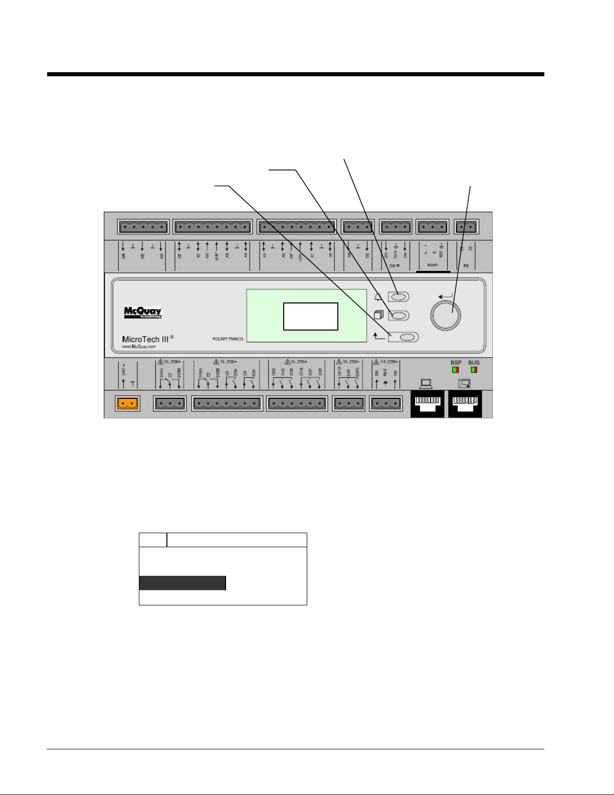
Using the Controller
>>>>
>>>>
>>>>
>>>>
Alarm Button
The Unit Controller Operation
Figure 11, Unit Controller
Menu Button
Navigation Wheel
Display
The keypad/display consists of a 5-line by 22-character display, three buttons (keys) and a
“push and roll” navigation wheel. There is an Alarm Button, Menu (Home) Button, and a
Back Button. The wheel is used to navigate between lines on a screen (page) and to
increase and decrease changeable values when editing. Pushing the wheel acts as an Enter
Button and will jump from a link to the next set of parameters.
56 OM 1051-2
Figure 12, Typical Screen
♦6
Status/Settings
Set Up
Temperature
Date/Time/Schedule
Generally, each line on the display contains a menu title, a parameter (such as a value or a
setpoint), or a link (which will have an arrow in the right of the line) to a further menu.
The first line visible on each display includes the menu title and the line number to which
the cursor is currently “pointing”, in the above case 3, Temperature.
The left most position of the title line includes an “up” arrow ▲ to indicate there are lines
(parameters) “above” the currently displayed line; and/or a “down” arrow ▼ to indicate
there are lines (parameters) “below” the currently displayed items or an “up/down” arrow
♦
to indicate there are lines “above and below” the currently displayed line. The selected
line is highlighted.
View/Set Unit 3

Each line on a screen can contain status-only information or include changeable data
Enter Password
>>>>
fields (setpoints).
When the cursor is on a line the highlights will look like this:
If line contains a changeable value-
If the line contains status-only
information-
Or a line in a menu may be a link to further menus. This is often referred to as a jump line,
meaning pushing the navigation wheel will cause a “jump” to a new menu. An arrow (
displayed to the far right of the line to indicate it is a “jump” line and the entire line is
highlighted when the cursor is on that line.
NOTE - Only menus and items that are applicable to the specific unit configuration are
displayed.
This manual includes information relative to the operator level of parameters; data and
setpoints necessary for the every day operation of the chiller. There are more extensive
menus available for the use of service technicians.
Evaporator Delta T= 10.0F
Unit Status= Run
>>>>
)is
Navigating
When power is applied to the control circuit, the controller screen will be active and display the
Home screen, which can also be accessed by pressing the Menu Button The navigating wheel is
the only navigating device necessary, although the MENU, ALARM, and BACK buttons can
provide shortcuts as explained later.
Passwords
Enter passwords from the Main Menu:
• Enter Password, links to the Entry screen, which is an editable screen So pressing the
wheel goes to the edit mode where the password (5321) can be entered. The first (*)
will be highlighted, rotate the wheel clockwise to the first number and set it by
pressing the wheel. Repeat for the remaining three numbers.
The password will time out after 10 minutes, and is cancelled if a new password is
entered or the control powers down.
• Not entering a password allows access to a limited number of parameters (with
asterisks) as shown in
Figure 13,
Figure 14,
Password Menu
Main Menu
Unit Status
Off: Unit Sw
ACTIVE SETPT 44.6°F
Password Entry Page
Enter Password
Enter PW ****
Figure 15
on page 60.
OM 1051-2 57

Entering an invalid password has the same effect as not entering a password.
Once a valid password has been entered, the controller allows further changes and access
without requiring the user to enter a password until either the password timer expires or a
different password is entered. The default value for this password timer is 10 minutes.
Navigation Mode
When the navigation wheel is turned clockwise, the cursor moves to the next line (down)
on the page. When the wheel is turned counter-clockwise the cursor moves to the previous
line (up) on the page. The faster the wheel is turned the faster the cursor moves. Pushing
the wheel acts as an “Enter” button.
Three types of lines exist:
• Menu title, displayed in the first line as in
• Link (also called Jump) having an arrow ( >>>> ) in the right of the line and used to link
to the next menu.
• Parameters with a value or adjustable setpoint.
For example, “Time Until Restart” jumps from level 1 to level 2 and stops there.
When the Back Button is pressed the display reverts back to the previously displayed
page. If the Back button is repeatedly pressed the display continues to revert one page
back along the current navigation path until the “main menu” is reached.
Figure 14
.
When the Menu (Home) Button is pressed the display reverts to the “main page.”
When the Alarm Button is depressed, the Alarm Lists menu is displayed.
Edit Mode
The Editing Mode is entered by pressing the navigation wheel while the cursor is pointing
to a line containing an editable field. Once in the edit mode pressing the wheel again
causes the editable field to be highlighted. Turning the wheel clockwise while the editable
field is highlighted causes the value to be increased. Turning the wheel counter-clockwise
while the editable field is highlighted causes the value to be decreased. The faster the
wheel is turned the faster the value is increased or decreased. Pressing the wheel again
cause the new value to be saved and the keypad/display to leave the edit mode and return
to the navigation mode.
A parameter with an “R” is read only; it is giving a value or description of a condition. An
“R/W indicates a read and/or write opportunity; a value can be read or changed (providing
the proper password has been entered).
Example 1: Check Status, for example -is the unit being controlled locally or by an external
network? We are looking for the Unit Control Source Since this a unit status parameter, start at
Main Menu and select View/Set Unit and press the wheel to jump to the next set of menus. There
will be an arrow at the right side of the box, indicating that a jump to the next level is required.
Press the wheel to execute the jump.
You will arrive at the Status/ Settings link. There is an arrow indicating that this line is a link to a
further menu. Press the wheel again to jump to the next menu, Unit Status/Settings.
Rotate the wheel to scroll down to Control Source and read the result.
Example 2; Change a Setpoint, the chilled water setpoint for example. This parameter is
designated as Cool LWT 1 setpoint and is a unit parameter. From the Main Menu select View/Set
Unit. The arrow indicated that this is link to a further menu.
58 OM 1051-2

Press the wheel and jump to the next menu View/Set Unit and use the wheel to scroll down to
Temperatures. This again has an arrow and is a link to a further menu. Press the wheel and jump
to the Temperatures menu, which contains temperatures values and setpoints. The first line is
Evap LWT, rotate wheel until Cool LWT 1 is highlighted. Press the wheel to enter edit mode.
Rotate wheel until new setpoint is reached, then press wheel to accept the new value and exit edit
mode.
Example 3; Clear an Alarm, from the Main Menu scroll down to the Alarms line. Note the
arrow indicating this line is a link. Press the wheel to jump to the next menu Alarms There are two
lines here; Alarm Active and Alarm Log. Alarms are cleared from the Active Alarm link. Press the
wheel to jump to the next screen. With the first line highlighted, press the wheel to enter edit
mode. Rotate wheel until AlmClr is set to On, then press wheel to clear the alarms.
OM 1051-2 59

Figure 15, HMI Keypad Navigation
Menu Level 1
Menu Level 2
Menu Leve l 3
Enter Pass word
Enter Password
Alarms
Alarms
Scheduled Mai ntenance
Alarm Active
Alarm Active
About This Chiller
Alarm Log
Active Alarm/W arning n
R
Alarm Entry 1
R
Starter Serial Number(s)
Starter Model Numbers
Application Version
R
Circuit #1
R/W
Menu Level 4
Menu Leve l 5
Cir1 Status
Visable (w/o Password)
Unit Status R
Active Setpo int R En ter PW R/W
Evap Leaving W ater Tem p R
Unit Capacity R
Unit Mode R
Next Maintenance
Next Maintenance M onth/Year R Acknowledge All R/W
Service Support Reference R
About This Chiller
Model Number R
G. O. Num ber R
Unit Serial Num ber R
Starter Model Number(s)
Active Alarm/W arning 1 R
… R
Alarm Log
… R
Alarm Entry 25 R
BSP Version R
HMI GU ID R Circuit #2 R/W
OBH GUID R Circuit #3 R/W
View/Set Circuit View/Set Circuit
Unit Status R
Active Setpo int R
Evap Leaving W ater Tem p R
Evap Enteri ng Wa ter Temp R
Unit Mode R
Circuit #1 View/Se t Cir1
Circuit #2 Data
Circuit #3 Status /Setting s
Circuit #4 Compre ssor
Circuit Status R
Circuit Mode R/W Circuit #1 Status R
Circuit Capacity R Circuit #2 Status R
Service Pumpdown R/W Ci rcuit #3 Status R
Circuit #4 R/W
Starter Serial Numbers
Circuit #1 R/W
Circuit #2 R/W
Circuit #3 R/W
Circuit #4 R/W
Condenser
EXV
Configuration
Calibrate Sensors
Circuit Status
Circuit #4 Status R
60 OM 1051-2

Optional Remote User Interface
The optional remote user interface is a remote control panel that mimics operation of the controller
located on the unit. Up to eight Pathfinder units can be connected to it and selected on the screen. It
provides HMI (Human Machine Interface) within a building, the building engineer’s office for
example, without going outdoors to the unit.
It can be ordered with the unit and shipped loose as a field installed option. It can also be ordered
anytime after chiller shipment and mounted and wired on the job as explained on the following page.
The remote panel is powered from the unit and no additional power supply is required.
All viewing and setpoint adjustments available on the unit controller are available on the remote panel.
Navigation is identical to the unit controller as described in this manual.
The initial screen when the remote is turned on shows the units connected to it. Highlight the desired
unit and press the wheel to access it. The remote will automatically show the units attached to it, no
initial entry is required.
Alarm Button
w/Flashing Red
Alarm Light
Menu Button
Back Button
Push and Roll
Navigating Wheel
OM 1051-2 61
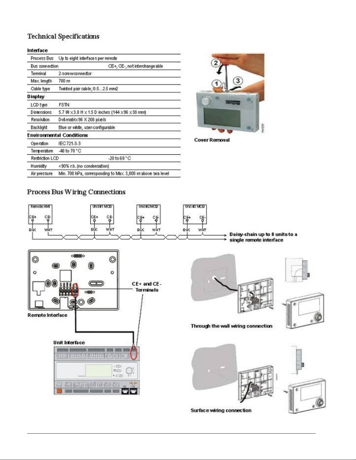
62 OM 1051-2

Optional Compressor VFD
An optional variable frequency drive (VFD) for each unit compressor provides compressor speed
reduction to the extent permissible by chiller load and discharge pressure requirements. The speed
reduction provides significant energy savings over fixed-speed compressors.
The VFD has its own microprocessor controller that monitors VFD operation, provides safety
shutdowns and sends data to the chiller controller.
VFD alarms and faults are handled the same as chiller related faults. See page 44 for information on
viewing and clearing them.
Access to the VFD enclosure is by factory-trained technicians only. Unauthorized entry can
result in property damage, severe personal injury, or death.
Faults and Minor Faults/Alarms
When the drive detects a fault:
• The VFD sends a message to the chiller controller regarding the fault
• The chiller controller displays a hexadecimal number code that identifies the specific VFD fault.
Table 8 lists the fault codes.
• An alarm bell icon will be displayed in the upper right-hand corner of all controller screens
including the optional remote user interface panel’s screens.
• The remote alarm circuit will be energized (wiring to a remote alarm device is optional)
• The drive output is interrupted and the compressor coasts to a stop.
• The drive is inoperable until the fault is corrected.
When the drive detects an alarm or minor fault:
!
WARNING
• No message is sent to the chiller controller since no operator action is required.
• The drive continues running the compressor.
Clearing VFD Faults
VFD faults are cleared in the same manor as any chiller unit fault. See page 44 for instructions.
Navigating VFD Fault Codes
When a VFD fault condition is detected, the VFD hexadecimal fault code will appear on the chiller
controller display (HMI) as a hexadecimal code, for example; 0002H. The faults that can be
corrected by the operator without accessing the VFD interior are listed in Table 8. Note the fault
code and contact McQuay Service if unsuccessful in clearing the listed faults or for assistance with
unlisted faults.
Table 8, Fault Code, Causes and Possible Solutions
Hexa-
decimal
Code
0083H CPF02
0095H
0097 CPF22
0019H dEv
VFD HMI
Display
CPF20,
CPF21
Fault Name,
Cause
A/D Conversion
Error
Control Circuit
Error
Hybrid IC
Error
Speed
Deviation
Table continued next page.
Possible Solutions
Cycle power to drive (Note 1)
Cycle power to drive (Note 1)
Cycle power to drive (Note 1)
Reduce compressor load
OM 1051-2 63
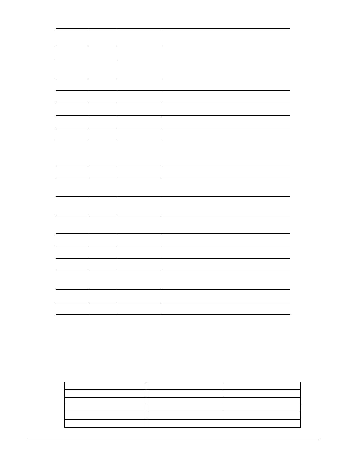
Hexa-
decimal
Code
001FH Err
0007H oC Overcurrent
0106H to
0107H
0111H,
0112H
0131H to
0139H
0205H to
0211H
0212H to
0217H
0231H to
0239H,
023AH to
023EH
0305H,
0306H
0009H oH
000AH oH1
000BH oL1
000CH oL2
0008H ov
000FH rr
0002H Uv1
0003F Uv2
0004H Uv3
VFD HMI
Display
oFA03 to
oFA06
oFA10,
oFA11
oFA30 to
oFA43
oFb03 to
oFb11
oFb12 to
oFb17
oFb30 to
oFb43
oFC05,
oFC06
Fault Name, Possible Solutions
EEPROM Write
Error
Option Card Error
Option Card Error
Option Card Error
Option Card Error
Option Card Error
Option Card Error
Option Card Error
Heatsink
Overheat
Heatsink
Overheat
Motor
Overload
Drive
Overload
Overvoltage
DC Bus
Braking Transistor
Failed
DC Bus
Undervoltage
Control Power
Fault
Bypass Circuit
Undervoltage
Measure the current going to the compressor
Determine if there is a sudden fluctuation in current
Verify ambient temperature within specification
Remove any adjacent heat producing equipment
Verify ambient temperature within specification
Remove any adjacent heat producing equipment
Check for power supply phase loss/fluctuation
Check for power supply phase loss/fluctuation
Cycle power to drive (Note 1)
Reduce load
Cycle power to drive (Note 1)
Cycle power to drive (Note 1)
Cycle power to drive (Note 1)
Cycle power to drive (Note 1)
Cycle power to drive (Note 1)
Cycle power to drive (Note 1)
Cycle power to drive (Note 1)
Decrease load
Decrease load
Reduce load
Check motor current against nameplate
Reduce load
Check motor wiring for ground faults
Check input voltage
Cycle power to drive (Note 1)
Check for loose power connections
Check supply voltage
Cycle power to drive (Note 1)
Cycle power to drive (Note 1)
Cycle power to drive (Note 1)
Note
1. Depending on the fault type, the fault will shut down the circuit or entire unit.
If a circuit is still running and on its own disconnect, it can be left running. Disconnect and then
reconnect the faulted circuit.
If a circuit is still running and there is a common disconnect for the unit, pump down the running
circuit, disconnect and reconnect the entire unit.
VFD Changes from Non-VFD
Table 9, Setpoint Changes
Setpoint VFD Units Non-VFD Units
Light Load Stage Down Default 35 Default 40
Stop Delta T Default 1.5 Default 0.7
Stage Up Delta T Default 0.5 Default 1.0
PVM Config Default None Default Single Point
Slide Position Sensor Default No Default Yes
64 OM 1051-2

Table 10, Logic Changes
Logic VFD Units Non-VFD Units
Requirements for
staging a circuit on
are different
Method for
generating
load/unload
commands is
different.
Pressure control
target is different
Limits of SSH
target are different
Triggers for
transition from
pressure control to
SSH control are
different.
Triggers for
transition from SSH
control to pressure
control are
different.
If a calculated limit for pulldown rate
is exceeded when LWT error is less
than 10°C, no additional circuit can
start.
A scaled limit on pulldown rate is
used in combination with a scaled
time delay between capacity
changes based on LWT error.
Always controls to 350 kPa other
than after transition from SSH
control
SSH target varies from 3.4 to 7.0 °C
(as DSH varies from 18 to 12 °C)
Circuit running for 3 minutes and
DSH >= 12 deg C for 1 minute or
SSH < SSH target plus 1 degree C.
Evap Pressure > 350 kPa for 60
seconds
Has the logic outlined in original SRS,
without the additional logic shown at
left for VFD chillers.
An error accumulator using LWT error
and loop pulldown rate are used. Time
between capacity changes is
determined by accumulator reaching
limit and the time delays in individual
circuits.
Allows pressure target to vary in order
to maintain DSH (12 to 22 °C)
SSH target varies from 2.8 to 5.5 °C
(as DSH varies from 17 to 12 °C)
Low Pressure Unload not active and
LWT <= 15.5°c and SSH >= SSH
target and DSH >= 12°C for at least 3
minutes
LWT > 17°C or DSH < 12°C
Control Panel
The control panel for VFD units is different from non-VFD units due to the space requirements of the
drive. See Figure 16 and Figure 17 for component layout.
OM 1051-2 65

Figure 16, Upper Section of the VFD Control Panel Section
Circuit #1
Optional
Fan VFD
Fan Contactors
& Overloads
Circuit #1
Optional
Fan VFD
Circuit #2
Figure 17, Lower Section of the VF Control Panel Section
D Net
Module
AC Module
Fan Contactors
& Overloads
Circuit #2
Unit & Circuit
Switches
Main unit
controller
Circuit
Control
Controller #1
Circuit
EEV #1
Controller #2
EEV #2
Control
Control
Compressor
Transformer
Thermistor
Boards 1 & 2
66 OM 1051-2

Optional Power Factor Correction Capacitors
the panel
Optional power factor correction capacitors (PFCC) located in an electrical panel may have
been ordered with the chiller. If so, there is one panel per compressor and they are mounted
on the side base rail near the evaporator.
The panel has no moving parts and no routine maintenance is required. There is a fuse for
each phase, each with a blown fuse indicator and associated red indicating light.
A fuse failure will cause a phase fault and the unit will experience a rapid shutdown from the
Phase-Voltage Monitor for wye-delta starters or internally within solid state starters. Units
with compressor VFDs will not normally have PFCCs.
Before replacing the fuse, the cause for failure must be determined and corrected. The
chiller will not run with a blown circuit fuse.
!
WARNING
Disconnect power from the unit before opening the capacitor panel. After disconnecting, allow ten
minutes for capacitor to discharge and check for no capacitor voltage with a voltmeter before
attempting any service work.
Failure to do so can result in property damage, severe personal injury, or death.
Blown fuse
indicators
Fuses, one
per phase
Power block
Red blown fuse indicator lights,
one per fuse, located on top of
Capacitor, some
units may have
two
OM 1051-2 67

Start-up and Shutdown
McQuay service personnel or factory authorized service agency
must perform initial start-up in order to activate warranty.
Most relays and terminals in the unit control center are powered when S1 is closed
and the control circuit disconnect is on. Therefore, do not close S1 until ready for
start-up or the unit may start unintentionally and possibly cause equipment damage.
Seasonal Start-up
1. Double check that the discharge shutoff valve and the optional compressor suction
butterfly valves are open.
2. Check that the manual liquid-line shutoff valves at the outlet of the subcooler coils
and the oil separator oil return line shutoff valves are open.
3. Check the leaving chilled water temperature setpoint on the MicroTech III controller
to be sure it is set at the desired chilled water temperature.
4. Start the auxiliary equipment for the installation by turning on the time clock, and/or
remote on/off switch, and chilled water pump.
NOTICE
!
CAUTION
5. Check to see that pumpdown switches Q1 and Q2 (and Q3) are in the "Pumpdown
and Stop" (open) position. Throw the S1 switch to the "auto" position.
6. Under the "Control Mode" menu of the keypad, place the unit into the automatic cool
mode.
7. Start the system by moving pumpdown switch Q1 to the "auto" position.
8. Repeat step 7 for Q2 (and Q3).
Temporary Shutdown
Move pumpdown switches Q1 and Q2 to the "Pumpdown and Stop" position. After the
compressors have pumped down, turn off the chilled water pump.
!
CAUTION
Do not turn the unit off using the "Override Stop" switch, without first moving Q1 and
Q2 (and Q3) to the "Stop" position, unless it is an emergency, as this will prevent the
unit from going through a proper shutdown/pumpdown sequence, resulting in
possible equipment damage.
68 OM 1051-2

!
CAUTION
The unit has a one-time pumpdown operation. When Q1 and Q2 are in the
"Pumpdown and Stop" position the unit will pump down once and not run again
until the Q1 and Q2 switches are moved to the auto position. If Q1 and Q2 are in
the auto position and the load has been satisfied, the unit will go into one-time
pumpdown and will remain off until the MicroTech III control senses a call for
cooling and starts the unit.
!
CAUTION
Water flow to the unit must not be interrupted before the compressors pump down
to avoid freeze-up in the evaporator. Interruption will cause equipment damage.
!
CAUTION
If all power to the unit is turned off, the compressor heaters will become
inoperable. Once power is resumed to the unit, the compressor and oil separator
heaters must be energized a minimum of 12 hours before attempting to start the
unit.
Failure to do so can damage the compressors due to excessive accumulation of
liquid in the compressor.
Start-up After Temporary Shutdown
1. Insure that the compressor and oil separator heaters have been energized for at least
12 hours prior to starting the unit.
2. Start the chilled water pump.
3. With System switch Q0 in the "on" position, move pumpdown switches Q1 and Q2 to
the "auto" position.
4. Observe the unit operation until the system has stabilized.
Extended (Seasonal) Shutdown
1. Move the Q1 and Q2 (and Q3) switches to the manual pumpdown position.
2. After the compressors have pumped down, turn off the chilled water pump.
3. Turn off all power to the unit and to the chilled water pump.
4. If fluid is left in the evaporator, confirm that the evaporator heaters are operational.
5. Move the emergency stop switch S1 to the "off" position.
6. Close the compressor discharge valve and the optional compressor suction valve (if
so equipped) as well as the liquid line shutoff valves.
7. Tag all opened compressor disconnect switches to warn against start-up before
opening the compressor suction valve and liquid line shutoff valves.
8. If glycol is not used in the system, drain all water from the unit evaporator and chilled
water piping if the unit is to be shutdown during winter and temperatures below -20°F
can be expected. The evaporator is equipped with heaters to help protect it down to 20°F. Chilled water piping must be protected with field-installed protection. Do not
leave the vessels or piping open to the atmosphere over the shutdown period.
9. Do not apply power to the evaporator heaters if the system is drained of fluids as this
can cause the heaters to burn out.
OM 1051-2 69

Start-up After Extended (Seasonal) Shutdown
1. With all electrical disconnects locked and tagged out, check all screw or lug-type
electrical connections to be sure they are tight for good electrical contact.
!
DANGER
LOCK AND TAG OUT ALL POWER SOURCES WHEN CHECKING
CONNECTIONS. ELECTRICAL SHOCK WILL CAUSE SEVERE PERSONAL
INJURY OR DEATH.
2. Check the voltage of the unit power supply and see that it is within the ±10%
tolerance that is allowed. Voltage unbalance between phases must be within ±3%.
3. See that all auxiliary control equipment is operative and that an adequate cooling load
is available for start-up.
4. Check all compressor flange connections for tightness to avoid refrigerant loss.
Always replace valve seal caps.
5. Make sure system switch Q0 is in the "Stop" position and pumpdown switches Q1
and Q2 are set to "Pumpdown and Stop", throw the main power and control
disconnect switches to "on." This will energize the crankcase heaters. Wait a
minimum of 12 hours before starting up unit. Turn compressor circuit breakers to
"off" position until ready to start unit.
6. Open the optional compressor suction butterfly as well as the liquid line shutoff
valves, compressor discharge valves.
7. Vent the air from the evaporator water side as well as from the system piping. Open
all water flow valves and start the chilled water pump. Check all piping for leaks and
recheck for air in the system. Verify the correct flow rate by taking the pressure drop
across the evaporator and checking the pressure drop curves in the installation
manual, IM 997.
8. The following table gives glycol concentrations required for freeze protection.
Table 11, Freeze Protection
Temperature
°°°°F (°°°°C)
20 (6.7) 16 18 11 12
10 (-12.2) 25 29 17 20
0 (-17.8) 33 36 22 24
-10 (-23.3) 39 42 26 28
-20 (-28.9) 44 46 30 30
-30 (-34.4) 48 50 30 33
-40 (-40.0) 52 54 30 35
-50 (-45.6) 56 57 30 35
-60 (-51.1) 60 60 30 35
Notes:
1. These figures are examples only and cannot be appropriate to every situation. Generally, for an extended
margin of protection, select a temperature at least 10°F lower than the expected lowest ambient
temperature. Inhibitor levels should be adjusted for solutions less than 25% glycol.
2. Glycol of less than 25% concentration is not recommended because of the potential for bacterial growth
and loss of heat transfer efficiency.
Ethylene Glycol Propylene Glycol Ethylene Glycol Propylene Glycol
Percent Volume Glycol Concentration Required
For Freeze Protection For Burst Protection
70 OM 1051-2
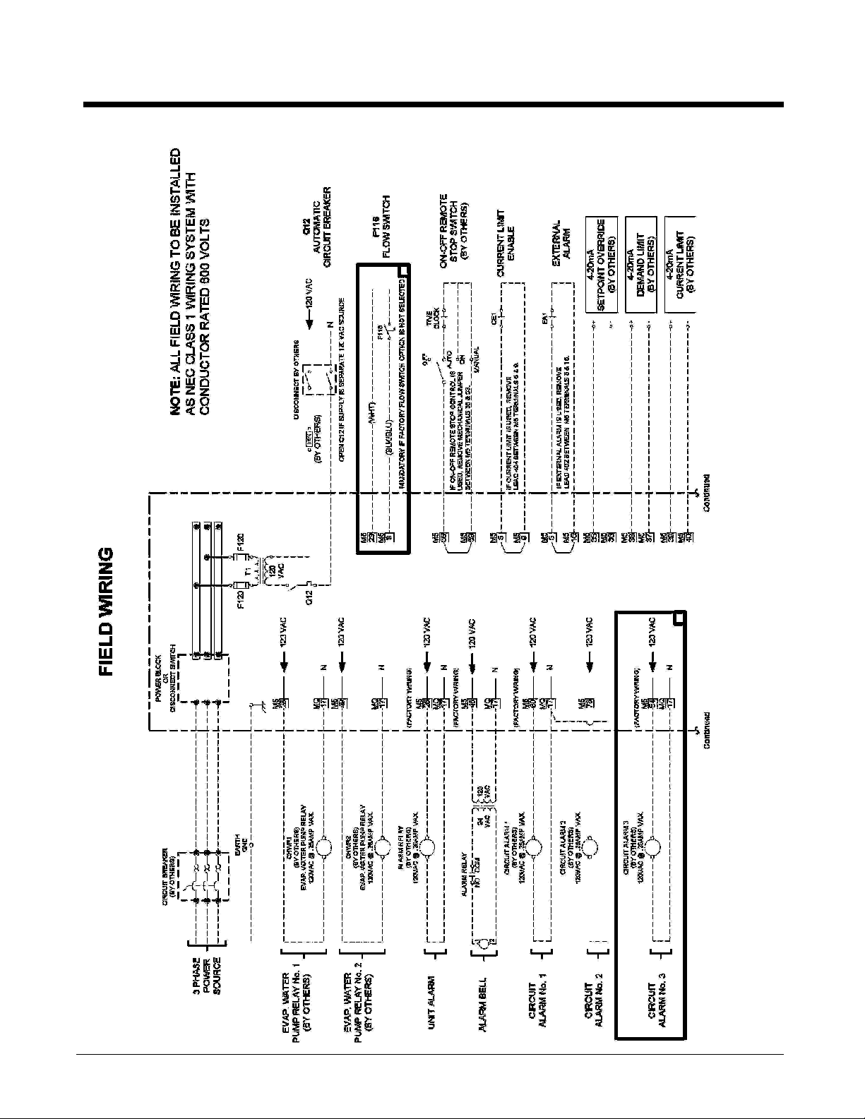
Field Wiring Diagram
Figure 18, Typical Field Wiring Diagram, Sheet 1
OM 1051-2 71

Figure 18, Typical Field Wiring Diagram, Sheet 12
NOTE:
1 The compressor alarms will not be energized by a unit fault, only the unit alarm will do so. Using the unit alarm and the
circuit alarms will include all faults and also designate which compressor has an alarm.
2 Field wiring for optional BAS continued on next page.
3 The BAS interface modules and the remote display shown above are available as options.
72 OM 1051-2

System Maintenance
General
On initial start-up and periodically during operation, it will be necessary to perform certain
routine service checks. Among these are checking the liquid line sight glasses, and the
compressor oil level sight glass. In addition, check the MicroTech III controller temperature and
pressure readings with gauges and thermometers to see that the unit has normal condensing and
suction pressure and superheat and subcooling readings. A recommended maintenance schedule
is located at the end of this section.
A Periodic Maintenance Log is located at the end of this manual. It is suggested that the log be
copied and a report be completed on a regular basis. The log will serve as a useful tool for a
service technician in the event service is required.
Initial start-up date, vibration readings, compressor megger readings and oil analysis
information should be kept for reference base-line data.
Compressor Maintenance
The semi-hermetic compressor requires no yearly scheduled maintenance. Compressor vibration
is an indicator of a possible problem requiring maintenance. It is recommended that the
compressor be checked with a vibration analyzer at, or shortly after, start-up and again on an
annual basis. The load should be maintained as closely as possible to the load of the original test.
The initial vibration analyzer test provides a benchmark of the compressor, and when performed
routinely, can give a warning of impending problems.
Lubrication
No routine lubrication is required on Pathfinder units. The fan motor bearings are permanently
lubricated. No further lubrication is required. Excessive fan motor bearing noise is an indication
of a potential bearing failure.
Compressor oil must be ICI RL68HB, McQuay Part Number 735030446 in a 1-gallon container.
This is synthetic polyolester oil with anti-wear additives and is highly hygroscopic. Care must be
taken to minimize exposure of the oil to air when charging oil into the system.
The oil charge is 6 gallons (23 liters) for all compressor sizes.
Oil Filter Removal and Renewal
Fitting a New Oil Filter Element – Dismantling
Prior to this procedure, pump out the compressor; isolate the electrical supply to the control panels and
compressor motor terminal.
!
WARNING
After the compressor has been pumped down and isolated, the oil contained inside the filter
housing will remain hot enough to cause burns for some time afterwards. Always allow
sufficient time for the oil to cool down so that it is cool enough not to be a danger when
drained off (less than 35 °C is recommended). Severe injury from burns can result.
OM 1051-2 73

Spigot
2
4
3
5
Sealing
1
1 Oil Filter - 250mm
2 Oil Filter Housing Cover
3 O-Ring – 89.5x3
4 O-Ring – 76.1x3.4
5 M8 Bolts
• Unscrew and remove two hex head side cover bolts 180° apart. Insert M8 guide studs into the
vacant holes.
• Remove remaining bolts, remove oil filter housing cover.
• Pull the oil filter off of the spigot and withdraw the oil filter from the housing and clean.
• Clean oil filter housing cover plate.
Fitting a New Oil Filter Element – Reassembly
Before assembly commences, remove any paint from joint faces. Inspect parts individually for
damage, ensure they are completely clean before laying them out on a sheet of clean paper in a
logical order ready for reassembly.
Use fresh refrigerant oil to lubricate parts during reassembly. New O-rings must be used.
• Insert new oil filter into the housing, ensuring the filter sits tightly on the sealing spigot.
• Replace the oil filter housing cover
Filter housing cover plate – 6xM8 Bolts Removal of the filter housing cover
74 OM 1051-2

Remove filter and clean oil filter housing. Clean all other
components. Replace the o-rings.
Electrical Terminals
!
DANGER
Electric equipment can cause electric shock which will cause severe personal injury or death. Turn off,
lock out and tag all power before continuing with following service. Panels can have more than one
power source.
!
CAUTION
Periodically check electrical terminals for tightness and tighten as required. Always use a back-up
wrench when tightening electrical terminals.
Condensers
The condensers are air-cooled and constructed of 3/8" (9.5mm) OD internally finned copper tubes
bonded in a staggered pattern into louvered aluminum fins. No maintenance is ordinarily required
except the routine removal of dirt and debris from the outside surface of the fins. McQuay
recommends the use of non-caustic, non-acidic, foaming coil cleaners available at most air
conditioning supply outlets. Flush the coil from the inside out.
!
WARNING
Use caution when applying coil cleaners. They can contain potentially harmful chemicals. Wear breathing
apparatus and protective clothing. Carefully follow the cleaner manufacturer’s MSDS sheets. Thoroughly
rinse all surfaces to remove any cleaner residue. Do not damage the fins during cleaning.
If the service technician has reason to believe that the refrigerant circuit contains noncondensables,
recovery of the noncondensables will be required, strictly following Clean Air Act regulations
governing refrigerant discharge to the atmosphere. The service Schrader valves are located on both
vertical coil headers on both sides of the unit at the control box end of the coil. Access panels are
located at the end of the condenser coil directly behind the control panel. Recover the
noncondensables with the unit off, after shutdown of 15 minutes or longer, to allow air to collect at
the top of the coil. Restart and run the unit for a brief period. If necessary, shut the unit off and
repeat the procedure. Follow accepted environmentally sound practices when removing refrigerant
from the unit.
OM 1051-2 75

Optional Compressor VFD
Inspection Area Inspection Points Corrective Action
General
Conductors and Wiring
Terminals
Relays and Contactors
Inspect equipment for discoloration
from overheating or deterioration.
Inspect for dirt, foreign particles, or dust
collection on components
Inspect wiring and connections for
discoloration, damage or heat stress.
Inspect terminals for loose, stripped, or
damaged connections
Inspect contactors and relay for
excessive noise during operation
Inspect coils for signs of overheating
such as melted or cracked insulation.
Replace damaged equipment as required.
Inspect door seal if so equipped.
Use dry air to clear foreign matter
Repair or replace damaged wire.
Tighten loose screws and replace damaged
screws or terminals.
Check coil voltage for over or under voltage
condition.
Replace damaged removable relays,
contactors or circuit board.
Liquid Line Sight Glass
Observe the refrigerant sight glasses (one per circuit) weekly. A clear glass of liquid indicates that
there is adequate refrigerant charge in the system to provide proper feed through the expansion
valve.
Bubbling refrigerant in the liquid line sight glass, during stable run conditions, may indicate that
there can be an electronic expansion valve (EXV) problem since the EXV regulates liquid
subcooling. Refrigerant gas flashing in the sight glass could also indicate an excessive pressure
drop in the liquid line, possibly due to a clogged filter-drier or a restriction elsewhere in the liquid
line.
An element inside the sight glass indicates the moisture condition corresponding to a given element
color. If the sight glass does not indicate a dry condition after about 12 hours of operation, the
circuit should be pumped down and the filter-drier changed. An oil acid test is also recommended.
Do not use the sight glass on the EXV body for refrigerant charging. Its purpose is to view the
position of the valve.
Lead-Lag
A feature on all Daikin McQuay Pathfinder air-cooled chillers is a system for alternating the sequence
in which the compressors start to balance the number of starts and run hours. Lead-Lag of the
refrigerant circuits is accomplished automatically through the MicroTech III controller. When in the
auto mode, the circuit with the fewest number of starts will be started first. If all circuits are operating
and a stage down in the number of operating compressors is required, the circuit with the most
operating hours will cycle off first. The operator can override the MicroTech III controller, and
manually select the lead circuit as circuit #1, #2 or #3.
76 OM 1051-2

Preventative Maintenance Schedule
PREVENTATIVE MAINTENANCE SCHEDULE
OPERATION WEEKLY
General
Complete unit log and review (Note 3) X
Inspect unit for loose or damaged components and visible leaks X
Inspect thermal insulation for integrity X
Clean and paint as required X
Electrical ( * including the optional VFD)
Sequence test controls * X
Check contactors for pitting, replace as required * X
Check terminals for tightness, tighten as necessary * X
Clean control panel interior * X
Clean control box fan filter (Note 7 ) * X
Visually inspect components for signs of overheating * X
Verify compressor and oil heater operation X
Megger compressor motor X
Refrigeration/Lubricant
Leak test X
Check liquid line sight glasses for clear flow X
Check compressor oil sight glass for correct level (lubricant charge) X
Check filter-drier pressure drop (see manual for spec) X
Check lubricant filter pressure drop (Note 6) X
Perform compressor vibration test X
Perform oil analysis test on compressor oil X
Condenser (air-cooled)
Clean condenser coils (Note 4) X
Check fan blades for tightness on shaft (Note 5) X
Check fans for loose rivets and cracks, check motor brackets X
Check coil fins for damage and straighten as necessary X
MONTHLY
(Note 1)
Notes:
1. Monthly operations include all weekly operations.
2. Annual (or spring start-up) operations include all weekly and monthly operations.
3. Log readings can be taken daily for a higher level of unit observation.
4. Coil cleaning can be required more frequently in areas with a high level of airborne particles.
5. Be sure fan motors are electrically locked out.
6. Replace the filter if pressure drop exceeds 20 psi.
7. The weekly fan filter cleaning schedule can be modified to meet job conditions. It is important that the
filter allows full air flow.
ANNUAL
(Note 2)
OM 1051-2 77

Appendix
Definitions
Active Setpoint
The active setpoint is the setting in effect at any given moment. This variation occurs on
setpoints that can be altered during normal operation. Resetting the chilled water leaving
temperature setpoint by one of several methods, such as return water temperature, is an
example.
Active Capacity Limit
The active setpoint is the setting in effect at any given moment. Any one of several
external inputs can limit a compressor’s capacity below its maximum value.
Condenser Saturated Temperature Target
The saturated condenser temperature target is calculated by first using the following
equation:
Sat condenser temp target raw = 0.833(evaporator sat temp) + 68.34
The “raw” value is the initial calculated value. This value is then limited to a range
defined by the Condenser Saturated Temperature Target minimum and maximum
setpoints. These setpoints simply cut off the value to a working range, and this range can
be limited to a single value if the two setpoints are set to the same value.
Dead Band
The dead band is a range of values surrounding a setpoint such that a change in the
variable occurring within the dead band range causes no action from the controller. For
example, if a temperature setpoint is 44°F and it has a dead band of ± 2 degrees F, nothing
will happen until the measured temperature is less than 42°F or more than 46°F.
DIN
Digital input, usually followed by a number designating the number of the input.
Error
In the context of this manual, “Error” is the difference between the actual value of a
variable and the target setting or setpoint.
Evaporator Approach
The evaporator approach is calculated for each circuit. The equation is as follows:
Evaporator Approach = LWT – Evaporator Saturated Temperature
See page 38 for more details
Evap Recirc Timer
A timing function, with a 30-second default, that holds off any reading of chilled water
for the duration of the timing setting. This delay allows the chilled water sensors
(especially water temperatures) to take a more accurate reading of the chilled water
system conditions.
EXV
Electronic expansion valve, used to control the flow of refrigerant to the evaporator,
controlled by the circuit microprocessor.
High Saturated Condenser – Hold Value
High Cond Hold Value = Max Saturated Condenser Value – 5 degrees F
78 OM 1051-2

This function prevents the compressor from loading whenever the pressure approaches
within 5 degrees of the maximum discharge pressure. The purpose is to keep the
compressor online during periods of possibly temporary elevated pressures.
High Saturated Condenser – Unload Value
High Cond Unload Value = Max Saturated Condenser Value – 3 degrees F
This function unloads the compressor whenever the pressure approaches within 3 degrees
of the maximum discharge pressure. The purpose is to keep the compressor online during
periods of possibly temporary elevated pressures.
Light Load Stg Dn Point
The percent load point at which one of two operating compressors will shut off,
transferring the unit load to the remaining compressor.
Load Limit
An external signal from the keypad, the BAS or a 4-20 ma signal that limits the
compressor loading to a designated percent of full load. Frequently used to limit unit
power input.
Load Balance
Load balance is a technique that equally distributes the total unit load among the running
compressors on a unit or group of units.
Low Ambient Lockout
Prevents the unit from operating (or starting) at ambient temperatures below the setpoint.
Low Pressure Unload Setpoint
The psi evaporator pressure setting at which the controller will unload the compressor
until a preset pressure is reached.
Low Pressure Hold Setpoint
The psi evaporator pressure setting at which the controller will not allow further
compressor loading.
Low/High Superheat Error
The difference between actual evaporator superheat and the superheat target.
LWT
Leaving water temperature. The “water” is any fluid used in the chiller circuit.
LWT Error
Error in the controller context is the difference between the value of a variable and the
setpoint. For example, if the LWT setpoint is 44°F and the actual temperature of the
water at a given moment is 46°F, the LWT error is +2 degrees.
LWT Slope
The LWT slope is an indication of the trend of the water temperature. It is calculated by
taking readings of the temperature every few seconds and subtracting them from the
previous value, over a rolling one minute interval.
ms
Milli-second
Maximum Saturated Condenser Temperature
The maximum saturated condenser temperature allowed is calculated based on the
compressor operational envelope.
OM 1051-2 79

OAT
Outside ambient air temperature
Offset
Offset is the difference between the actual value of a variable (such as temperature or
pressure) and the reading shown on the microprocessor as a result of the sensor signal.
pLAN
Peco Local Area Network is the proprietary name of the network connecting the control
elements.
Refrigerant Saturated Temperature
Refrigerant saturated temperature is calculated from the pressure sensor readings for each
circuit. The pressure is fitted to an R-134a temperature/pressure curve to determine the
saturated temperature.
Soft Load
Soft Loading is a configurable function used to ramp up the unit capacity over a given
time period, usually used to influence building electrical demand by gradually loading the
unit.
SP
Setpoint
SSS
Solid state starter as used on McQuay screw compressors.
Suction Superheat
Suction superheat is calculated for each circuit using the following equation:
Suction Superheat = Suction Temperature – Evaporator Saturated Temperature
See page 38 for details.
Stage Up/Down Accumulator
The accumulator can be thought of as a bank storing occurrences that indicate the need
for an additional fan.
Stageup/Stagedown Delta-T
Staging is the act of starting or stopping a compressor or fan when another is still
operating. Startup and Stop is the act of starting the first compressor or fan and stopping
the last compressor or fan. The Delta-T is the “dead band” on either side of the setpoint
in which no action is taken.
Stage Up Delay
The time delay from the start of the first compressor to the start of the second.
Startup Delta-T
Number of degrees above the LWT setpoint required to start the first compressor.
Stop Delta-T
Number of degrees below the LWT setpoint required for the last compressor to stop.
VDC
Volts, Direct current, sometimes noted as vdc.
80 OM 1051-2


McQuay Training and Development
Now that you have made an investment in modern, efficient McQuay equipment, its care should be a
high priority. For training information on all McQuay HVAC products, please visit us at
www.mcquay.com and click on Training, or call 540-248-9646 and ask for the Training Department.
Warranty
All McQuay equipment is sold pursuant to McQuay’s Standard Terms and Conditions of Sale and
Limited Product Warranty. Consult your local McQuay Representative for warranty details. Refer to
form 933-430285Y. To find your local representative, go to www.mcquay.com.
This document contains the most current product information as of this printing. For the most up-todate product information, please go to www.mcquay.com.
(800) 432-1342 • www.mcquay.com OM 1051-2 (09/10)
 Loading...