

Page 1
AAF-HermanNelson
Classroom Unit Ventilators
Models AVS, AVB, AVV and AVR Floor Units
Catalog UV1600
C
Page 2

Contents
Introduction 3
AAF-HermanNelson Classroom Unit Ventilators 3
The Model AV Floor Unit 4
Features & Benefits 5
Quiet Operation With Our GentleFlo Delivery 5
The Right Amount of Fresh Air and Cooling 6
Precise Temperature and Dehumidification Control 7
Low Installation Costs 9
Low Operating Costs 10
Easy To Maintain 11
Built To Last 13
MicroTech II Controls 15
MicroTech II Controls For Superior Performance, Easy Integration 15
Control Modes and Functions 17
Advanced Control Options 19
System Components 21
Accessories 25
Wall Louvers & Grilles 25
Ventimatic™ Shutter Room Exhaust Ventilation 26
Storage Cabinets, Sink & Bubbler 27
End Panels, Filler Sections & Sub-Bases 28
Application Considerations 29
Why Classrooms Overheat 29
Meeting IAQ Requirements 31
Following ASHRAE Control Cycle II 31
Meeting ARI 840 Requirements 32
Meeting IBC Seismic Requirements 33
Face & Bypass Temperature Control 34
Modulating Valve Temperature Control 36
Coil Selection 37
DX Split Systems 38
Window Downdraft Protection 40
Digital Ready Systems 43
Field-Installed Controls By
Others & Digital Ready Controls 43
Unit Installation 48
Unit Arrangements: 16-5/8" Deep 51
Unit Arrangements: 21-7/8" Deep 52
Coil Selection 55
Quick Selection Procedure 55
Coil Selection Procedure 56
Chilled Water Selection Example 58
Hot Water Heating Selection 60
Steam Heating Selection 63
Electric Heating Selection 64
Direct Expansion Cooling Coil Selection 65
Valve Selection 66
Face and Bypass End-Of-Cycle Valve Sizing & Piping 66
Modulating Valve Sizing & Piping 68
Steam Valve Sizing & Piping 70
General Data 72
AV General Data 72
Available Unit Ventilator Combinations 73
Available Coil Combinations 75
Details & Dimensions 76
Coil Connections 76
Condensate Drain Connections 79
16-5/8” (422 mm) Deep Unit Arrangements 80
21-7/8" Deep Arrangements 82
End Panels 87
Valve Dimensions 88
Wall Intake Louvers & Grilles 89
Ventimatic Shutter Assembly 90
Sink & Bubbler Cabinet 91
Filler Sections & Utility Compartment 92
Shelf Storage Cabinets 93
Finned Tube Radiation Cabinets 95
Wiring Diagrams 96
Typical MicroTech II Wiring Diagrams 96
Typical Digital Ready Wiring Diagram 99
Typical Controls By Others Wiring Diagram 100
Guide Specifications 101
AAF-HermanNelson Unit Ventilator Model AV Guide Specifications 101
The ventilation rate of AAFHermanNelson unit
ventilators is certified and
tested per Air Conditioning
and Refrigeration Institute
(ARI) Standard 840.
McQuay is a registered trademark and MicroTech II, Digital Ready, GentleFlo, ServiceTools,
Microsoft is a registered trademark and Windows is a trademark of Microsoft Corporation.
and Protocol Selectability are trademarks of McQuay International.
Copyright © 2005 McQuay International. All rights reserved throughout the world.
C
Page 3
Introduction
Introduction
AAF-HermanNelson Classroom Unit Ventilators
Low Installation Costs
New construction installations are easily accomplished
with AAF-HermanNelson unit ventilators because they
avoid the added cost and space required for expensive
ductwork. Retrofit installations are also economical
because new units fit the same space occupied by
existing ones. Multiple control options—including
MicroTech II controls with Protocol Selectability™, or
For more than 85 years, schools have relied on
AAF-HermanNelson unit ventilators to keep classrooms
comfortable. Students learn more readily in a quiet, wellventilated environment. That’s why Herman Nelson
invented the unit ventilator and why we remain
committed to meeting the changing requirements of
schools with the highest quality products available.
We realize that keeping expenditures down is a high
priority for school administrators and school boards.
AAF-HermanNelson unit ventilators are inexpensive to
install and operate, and they are designed and built to
provide decades of trouble-free service.
Quiet Operation
AAF-HermanNelson unit ventilators are engineered and
manufactured to deliver quiet, continuous comfort. We
developed our GentleFlo™ air moving system to minimize
operating sound levels—even as demands for more fresh
air require units to operate longer and work harder.
The Right Amount of Fresh Air and Cooling
AAF-HermanNelson unit ventilators deliver required
amounts of fresh air to meet ventilation requirements,
and added cooling capacity to maintain consistent
comfort for students and teachers. Our Economizer
Operation, Demand Control Ventilation (DCV) and Part
Load, Variable Air options allow you to closely match
comfort requirements and reduce operating costs.
Precise Temperature and Dehumidification Control
AAF-HermanNelson unit ventilators feature precise
temperature and dehumidification control to keep
students and teachers comfortable while making
maximum use of “free” outdoor-air cooling to reduce
operating costs. They utilize a draw-thru air design that
contributes to even heat transfer and uniform discharge
air temperatures into the classroom. Coupled with face
and bypass air control and our MicroTech
passive dehumidification control strategies, they provide
precise control of temperature and humidity levels.
II™ active and
Digital Ready™ features—provide easy, low cost
integration into the building automation system of your
choice.
Low Operating Costs
When running, AAF-HermanNelson unit ventilators can
use as little electricity as two 100-watt light bulbs. They
take maximum advantage of “free” cooling opportunities
to reduce operating costs. During unoccupied periods
and at night, units operate sparingly to conserve energy.
Easy To Maintain, Modular Design
AAF-HermanNelson Unit Ventilators are designed to
provide easy access for maintenance and service
personnel to all serviceable components. Most tasks are
easily handled by a single person.
Built To Last
Our proven institutional design can withstand the rigors
of the classroom environment. It features an extra-sturdy
chassis and double-wall damper on the inside; scuffresistant finishes and tamper prevention features on the
outside. In fact, many units installed over 30 years ago
continue to provide quiet, reliable classroom comfort.
MicroTech II Control For Superior Performance, Easy Integration
AAF-HermanNelson unit ventilators can be equipped
with MicroTech II™ unit controllers for superior
performance. Factory integrated and tested controller,
sensor, actuator and unit options promote quick, reliable
start-up and minimize costly field commissioning. Our
Protocol Selectability feature provides easy, low-cost
integration into most building automation systems. Select
BACnet
communications to communicate control and monitoring
information to your BAS, without the need for costly
gateways. Unit controllers are L
the optional L
®
, LonTalk® or Metasys® N2 Open
ONWORKS
®
communication module.
ONMARK
®
certified with
AAF-HermanNelson Model AV Unit Ventilators 3
Page 4

Introduction
The Model AV Floor Unit
Our Model AV is a vertical, floor-standing unit that utilizes
remotely-supplied chilled water or refrigerant for cooling,
and hot water, steam or electric heat for heating. The
Model AV also can be supplied as a heating/ventilating
unit only or as a cooling/ventilating unit only.
The Model AV is just right for new construction and for
retrofit applications. Older buildings with baseboard
Hinged Top Access Doors
Welded OnePiece Chassis
Sampling
Chamber
Draw-Thru
Air Flow
Quiet, Aerodynamic Fans
radiant heat or other hydronic heating systems can be
easily adapted to work efficiently with Model AV units.
Chilled-water or refrigerant cooling can be added to
provide year-round comfort. The major features of this
model are shown below and described in more detail on
the following pages.
Fan Motor Out
Of Airstream
MicroTech II Controls
Composite
Drain Pan
Sectionalized
Access Panels
Face And Bypass
Damper Design
• Welded One-Piece Chassis offers
superior strength, durability, and vibration reduction.
• Unique Draw-Thru Design provides
uniform air distribution across the coil
for even discharge air temperatures.
• Quiet, Aerodynamic Fans utilize
GentleFlo technology for exceptionally
quiet unit operation.
• Modular Fan Section improves
balance, alignment and simplifies
maintenance.
• Fan Motor Located Out Of Air
Stream and away from heating coil
reduces heat exposure to prolong life.
• Face And Bypass Damper Design
provides superior dehumidification
and reduces chance of coil freeze-up
Advanced Heat
Transfer Coil
• Certified Ventilation Performance
per ARI-840.
• MicroTech II Controls provide supe-
rior comfort control and easy
integration into the building automation system of your choice.
• Advanced Heat Transfer Coil design
provides extra capacity.
• Sturdy Cabinet Construction
includes hidden reinforcement, a nonglare textured surface, and a tough,
scuff- and mar-resistant finish to make
the top sturdy enough to support
maintenance personnel.
• Sectionalized Front Access Panels
provide easy access to unit interior.
Panels are easily removed by a single
person. Front side panels can be
removed while unit is running.
Single Full-Length
Air Filter
Sturdy Cabinet
• Two Hinged Top Access Doors pro-
vide easy access to motor and end
bearing. Special tamper-resistant fasteners deter unauthorized access.
• Sampling Chamber for unit-mounted
sensor provides accurate sensing of
room temperature.
• Indoor Room Air Damper blocks
unwanted gusts of outdoor air on
windy days. Its nylon bearings are
quiet and maintenance free.
• Insulated Double-Wall Outdoor Air
Damper seals tightly without twisting.
• Single Full-length Air Filter is effi-
cient and easy to replace. All air
delivered to classroom is filtered.
• UL/cUL Listed
4 McQuay Catalog 1600
Page 5
Features & Benefits
Features & Benefits
Quiet Operation With Our GentleFlo Delivery
AAF-HermanNelson unit ventilators are engineered and
manufactured to deliver quiet, continuous comfort. We
developed our GentleFlo™ air moving system to
minimize operating sound levels—even as demands for
more fresh air require units to operate longer and work
harder. GentleFlo features include:
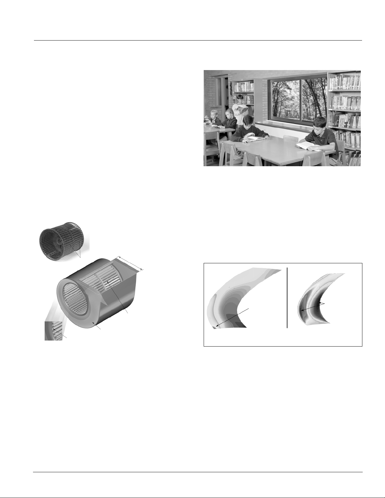
• Fan wheels are large, wide and rotate at a low speed
to reduce fan sound levels. They are impact-resistant
and carefully balanced to provide consistent
performance.
• Offset, aerodynamic fan wheel blades move air
efficiently (
• Precision tolerances help reduce flow and pressure
turbulence, resulting in lower sound levels.
• Fan housings incorporate the latest logarithmicexpansion technology for smoother, quieter air flow
(
Figure 2).
Figure 1. GentleFlo Fan Technology
Figure 1).
Expanded discharge air
opening
• A large, expanded discharge opening minimizes air
resistance, further lowering sound levels.
• Modular fan construction contributes to equal outlet
velocities and promotes quiet operation.
• Fan shafts are of ground and polished steel to
minimize deflections and provide consistent, long-term
operation.
• Fan assemblies are balanced before unit assembly,
then tested after assembly (and rebalanced if
necessary) to provide stable, quiet operation.
Figure 2. GentleFlo Reduces Turbulence
Minimal
Offset aerodynamic blades
Logarithmic expansion
housing
Precision Tolerances
AAF-HermanNelson Model AV Unit Ventilators 5
GentleFlo fan blade design
turbulence
Typical fan blade design
High turbulence
Page 6
Features & Benefits
The Right Amount of Fresh Air and Cooling
AAF-HermanNelson unit ventilators deliver required
amounts of fresh air to meet ventilation requirements and
added cooling capacity to maintain consistent comfort for
students and teachers. Our Economizer Operation,
Demand Control Ventilation (DCV) and Part Load,
Variable Air options allow you to match classroom
comfort requirements even more closely, and reduce
operating costs.
This means that you can be confident that your school is
meeting ventilation standards for Indoor Air Quality and
that your students are receiving adequate air to be
attentive to instruction. At the same time, you are saving
money in early morning hours, between classes or after
hours when classrooms are heated and cooled but not
always fully occupied.
Economizer Operation
It is well recognized that cooling, not heating, is the main
thermal challenge in school classrooms. The typical
classroom is cooled by outdoor air over half the time,
even in cold climates. It is therefore essential that unit
ventilators efficiently deliver outdoor air when classroom
conditions call for “free” or economizer cooling.
With AAF-HermanNelson unit ventilators, you can have
outdoor air whenever it is needed. Economizer operation
is facilitated by the outdoor air damper, which
automatically adjusts the above-minimum outside air
position to provide free cooling when the outdoor air
temperature is appropriate (
with MicroTech II controls, three levels of economizer
control are available (see
Figure 3. Full Economizer Mode
100% Outdoor Air Into Classroom
Figure 3). On units equipped
page 17).
Part-Load Variable Air Control
Part Load Variable Air control can be used in conjunction
with face and bypass damper temperature control to
automatically adjust the unit ventilator fan speed based
upon the room load and the room temperature. This
MicroTech II control option provides higher latent cooling
capabilities and quieter operation during non-peak load
periods by basing indoor fan speed upon room load.
Lower fan speeds in conjunction with our GentleFlo fan
technology (see page
page 5) contributes to a very quiet
classroom environment.
Room-temperature PI control loops determine the speed
of the fan, which varies according to the room load. It
also provides a built-in delay to prevent overshooting for
better comfort control. The outdoor air damper’s
minimum-air position is adjusted with the fan speed to
bring in a constant amount of fresh air.
Demand Control Ventilation
AAF-HermanNelson unit ventilators can be equipped to
use input from a CO
based on actual occupancy instead of a fixed design
occupancy. This Demand Controlled Ventilation (DCV)
system monitors the amount of CO
outdoor air is introduced to maintain good air quality. The
system is designed to achieve a target ventilation rate
(e.g., 15 cfm/person) based on actual occupancy.
By using DCV to monitor the actual occupancy pattern in
a room, the system can allow code-specific levels of
outdoor air to be delivered when needed. Unnecessary
over-ventilation is avoided during periods of low or
intermittent occupancy, leading to improved energy
efficiencies and cost savings.
controller to ventilate the space
2
so enough fresh
2
Face &
Bypass
Damper
Room Air
Damper
6 McQuay Catalog 1600
Filter
Outdoor Air
Damper
Outdoor Air
Page 7

Features & Benefits
Precise Temperature and Dehumidification Control
AAF-HermanNelson unit ventilators provide precise
temperature and dehumidification control to keep
students and teachers comfortable while making
maximum use of “free” outdoor-air cooling to reduce
operating costs. They utilize a draw-thru fan design that
contributes to even heat transfer and provides uniform
discharge air temperatures into the classroom. Coupled
with face and bypass damper air control and/or our
MicroTech
II active and passive dehumidification control
strategies, they provide precise control of temperature
and humidity levels under both part-load and full-load
conditions.
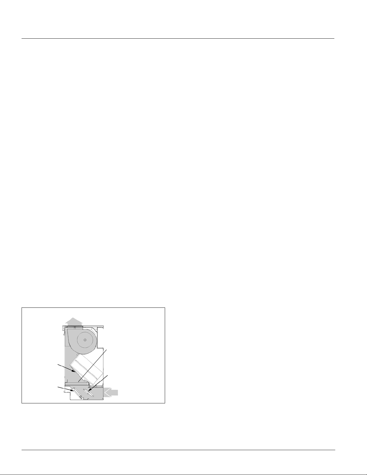
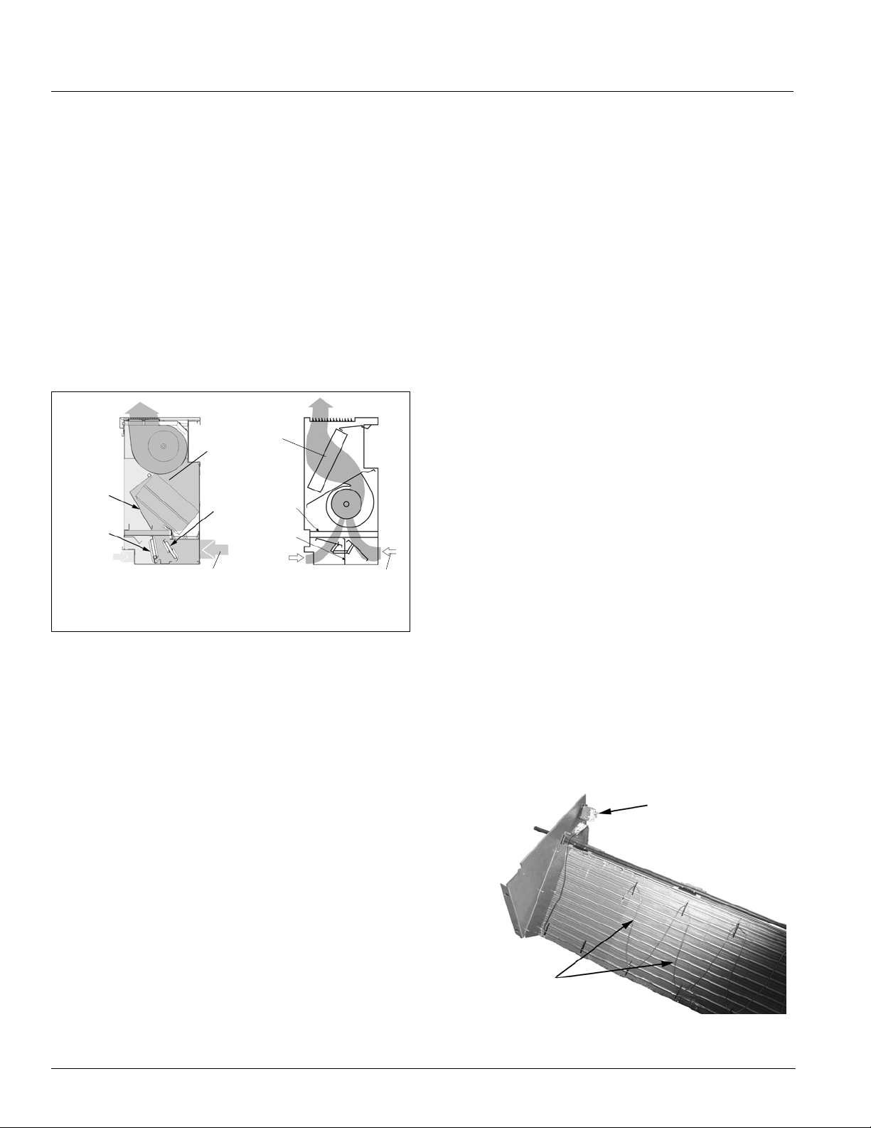
Draw-Thru Design For Even Discharge Temperatures
The AAF-HermanNelson Draw-Thru design sets our unit
ventilators apart from most competitive models. With this
system, fans draw air through the entire heat transfer
element (
concentrated areas of the coil element. The result is
more uniform discharge air temperatures into the
classroom and more efficient unit ventilator operation.
Figure 4. Draw-Thru Design Provides Even Discharge Air
Figure 4) rather than blowing it through highly
Uniform Discharge Air (Shaded)
Motor
Fans
Condenser
Ta bl e s 1 and 2 below compare the composition of the air
streams through the coil and air streams bypassing the
coil at various bypass air percentages for draw-thru and
blow-thru unit ventilators using 450 cfm of outdoor air. At
both 0% bypass air and 100% bypass air, no difference
exists in the composition of the air streams. However, at
all other bypass air percentages (part load), significant
differences are evident.
For instance, compare the 1500 cfm draw-thru (Ta bl e 1)
and blow-thru (Tab le 2) units at 70% bypass air. At this
point, the draw-thru unit still has all of the outdoor air
going through the coil. Meanwhile, the blow-thru unit is
bypassing 70% (315 cfm) of the humid outdoor air
directly into the classroom.
Table 1: AAF-Herman Nelson 1500 CFM Draw-Thru Unit
Bypass Air Stream CFM Cold Air Stream CFM
Tot al
% Bypass Air
0 1500 0 0 0 1500 1050 450
10 1500 150 150 0 1350 900 450
20 1500 300 300 0 1200 750 450
30 1500 450 450 0 1050 600 450
40 1500 600 600 0 900 450 450
50 1500 750 750 0 750 300 450
60 1500 900 900 0 600 150 450
70 1500 1050 1050 0 450 0 450
80 1500 1200 1050 150 300 0 300
90 1500 1350 1050 300 150 0 150
100 1500 1500 1050 450 0 0 0
Bypass
Total Unit CFM
From
Room
From
Outdoors
Tot al
Coil
From
Room
From
Outdoors
Table 2: 1500 CFM Blow-Thru Unit
Face & Bypass Design For Better Temperature and Humidity Control
When coupled with our draw-thru design, face and
bypass damper air control offers maximum
dehumidification and optimal temperature control. That’s
because indoor and outdoor air streams can be
separated until it is optimal to mix them.
During most part-load conditions, humid outdoor air is
directed through the cold coil (coil surface below the dew
point) where moisture is removed. Room air is bypassed
around the coil, since it has already been dehumidified.
This arrangement allows for maximum condensate
removal. Humid outdoor air is not bypassed around the
coil until the total amount of cooling air required is less
than the total amount of fresh outdoor air required in the
% Bypass Air
0 1500 0 0 0 1500 1050 450
10 1500 150 105 45 1350 945 405
20 1500 300 210 90 1200 840 360
30 1500 450 315 135 1050 735 315
40 1500 600 600 0 900 450 450
50 1500 750 525 225 750 525
60 1500 900 630 270 600 420 180
70 1500 1050 735 315 450 315 135
80 1500 1200 840 360 300 210 90
90 1500 1350 945 405 150 105 45
100 1500 1500 1050 450 0 0 0
Bypass Air Stream CFM Cold Air Stream CFM
Tot al
Bypass
Total Unit CFM
From
Room
From
Outdoors
Tot al
Coil
From
Room
From
Outdoors
225
room.
AAF-HermanNelson Model AV Unit Ventilators 7
Page 8
Features & Benefits
This illustrates that the most effective way to maintain an
acceptable humidity level with a chilled-water unit
ventilator system is to use a face and bypass damper,
draw-thru unit.
Why Blow-Thru Designs Don’t Measure Up
Blow-thru designs cannot provide comfort like this. With
blow-thru designs, the humid outside air is pre-mixed
with the room air before it can go through the coil
(
Figure 5). Dehumidification occurs only to the portion of
the air that is directed unevenly through the cooling coil.
The air that bypasses the coil is largely humid outdoor
air, resulting in unconditioned air being bypassed and
creating poor comfort conditions.
Figure 5. Draw-Thru Vs. Blow-Thru Design
Coil
Face &
Bypass
Damper
Room Air
Damper
Room Air
AAF-HermanNelson
Draw-Thru Design
Outdoor
Air Damper
Outdoor Air
With a blow-thru design the positive pressure of the fan
discharge can create areas across the coil of varying
temperatures and airflow. In addition, blow-thru face and
bypass damper construction picks up heat by wiping the
coil, creating overheating conditions. The sound level in
a blow-thru design also varies based upon the position of
the face and bypass damper.
Coil
Filter
RA/OA
Divider
Room Air
Outdoor Air
Blow-Thru Design
See “Active Dehumidification Control (Reheat)” on page
20 for more information.
Passive Dehumidification (Optional)
On units with face and bypass damper air control and
MicroTech II part-load variable air control, passive
dehumidification can be used under high humidity
conditions to keep classrooms comfortable. A unitmounted humidity sensor and fan speed changes are
utilized to improve latent cooling by keeping the air in
closer contact with the cold coil for passive
dehumidification.
This occurs in the unoccupied mode as the unit operates
to satisfy the unoccupied temperature and humidity set
points with the outside damper closed. The face and
bypass damper is placed in a minimum face position to
promote high latent cooling. The unit fan continues to
operate on low speed until the load is satisfied. This is
very helpful in high humidity areas where high night time
humidity can be absorbed in the building during off
hours.
Increased Coil Freeze Protection
AAF-HermanNelson units equipped with face and
bypass damper control provide extra protection from coil
freeze-up. That’s because there is a constant flow of hot
water through the coil, and water that is flowing typically
does not freeze. Additionally, all AAF-HermanNelson
units feature a double-walled, insulated outdoor air
damper with airtight mohair seals to prevent unwanted
coil air from entering the unit.
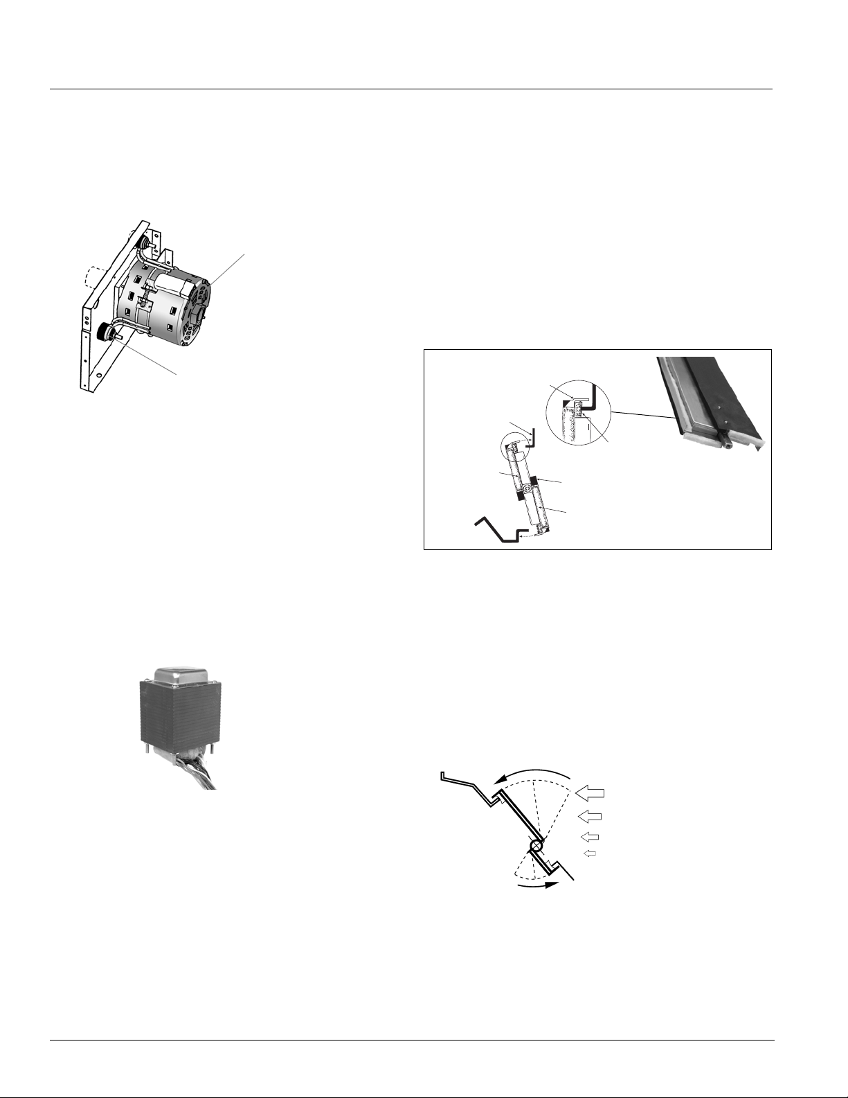
Furthermore, a low-temperature freezestat is factory
installed on all units with hydronic coils. Its serpentine
capillary tube senses temperatures across the leaving air
side of the coil, allowing the unit controller to react
quickly to low-temperature conditions.
Active Dehumidification (Reheat)
In high-humidity applications where valve-controlled,
Figure 6. Freezestat
Freezestat
reheat units are used, the Active Dehumidification
Control (ADC) sequence should be considered. During
excessive humidity conditions, a humidity sensor directs
the unit to continue cooling past the room setpoint to
remove excess moisture. Hydronic heat or electric heat
is then used to reheat the discharge air to maintain
acceptable room temperatures.
MicroTech II controls minimize the amount of reheat
needed to maintain relative humidity below a preset limit.
Capillary Tube
Reheat is used only when required and in the most
energy-efficient manner possible.
8 McQuay Catalog 1600
Page 9
Features & Benefits
Low Installation Costs
AAF-HermanNelson unit ventilators have many features
that make them economical to purchase and to install in
both new construction and retrofit applications. It is this
attention to detail and understanding of school
applications that make them the system of choice.
Perfect For Both New & Retrofit Applications
New construction installations are easily accomplished
with AAF-HermanNelson unit ventilators because they
avoid the added cost and space required for expensive
ductwork. Further savings can be realized because
piping installations use less space than duct systems.
This is important in existing buildings and also in new
construction where floor-to-floor heights can be reduced,
saving on overall building costs.
Retrofit installations are also economical because new
units fit the same space occupied by existing ones. Using
AAF-HermanNelson unit ventilators, central equipment,
such as chillers, can be sized smaller using building
diversity. This results in a low capital-cost system.
Built In Flexibility
AAF-HermanNelson unit ventilators include features that
make them easy to set up and reconfigure as needed to
meet special requirements. These features include:
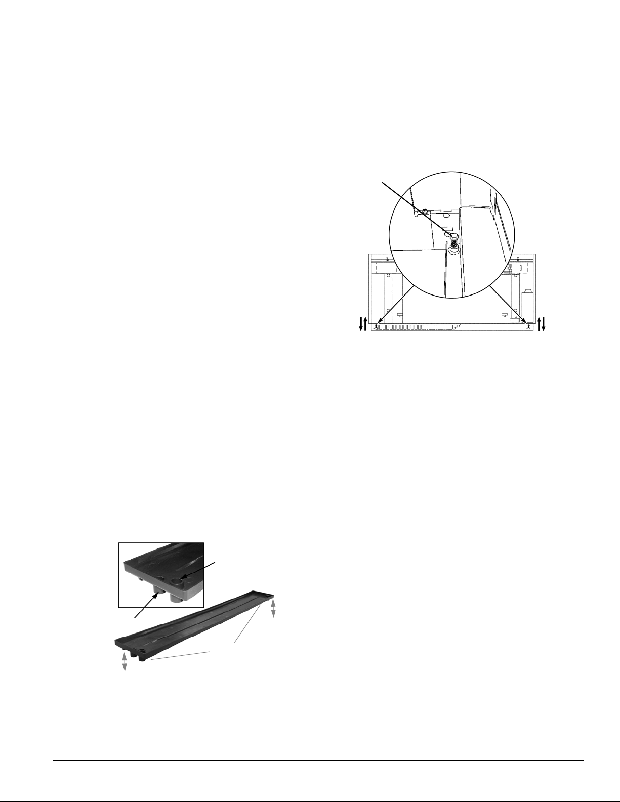
• Reversible Drain Connections All units come with a
composite drain pan that has drain connections on
either end (
connection is also provided. The drain-side connection
can be selected in the field. The direction in which the
drain pan slants can also be field-modified.
Figure 7. Composite Drain Pan, Reversible Connections
• Add Cooling At A Later Date Because we recognize
that some schools may wish to add cooling at a later
date, even heating-only units are shipped standard
with a composite drain pan.
Figure 7). A secondary, overflow drain
Secondary Overflow
Drain Connection
Primary Drain
Connection
Connect Drains On Either
End, Slant Pan To Either
End, Can Field-Modify
• Adjustable Leg Levelers Adjustable leg levelers are
furnished on the front legs of all floor units to
compensate for floor irregularities (
Figure 8. Adjustable Leg Levelers
Leg Leveler
Figure 8).
• Built-in Pipe Tunnel A built-in pipe tunnel allows field
crossover of hot-water or chilled-water piping,
electrical conduit or refrigeration tubing (see Unit
Arrangements beginning on page
51).
• Built-In Wire Race A built-in metal wire race runs from
one end of the unit to the other to provide extra
protection for wires and protect them from unit air.
Controls Flexibility
Multiple control options—including MicroTech II controls
with our Protocol Selectability feature—provide easy, low
cost integration of AAF-HermanNelson unit ventilators
into the building automation system of your choice (see
page 15). You can also operate these units individually or
in a master-slave control configuration.
With MicroTech II controls, you select BACnet, LonTalk
or Metasys
and monitoring information to your BAS, without the
need for costly gateways. Unit controllers are L
certified with the optional L
module.
Controls and communication modules can be factory
provided or field-installed by others. Factory integrated
and tested controller, sensor, actuator and unit options
promote quick, reliable start-up and minimize costly field
commissioning.
You can also use our Digital Ready option, where we
factory-install and pre-wire control sensors and actuators
and the controller is field-installed by others. See
Ready Systems” on page 43.
N2 communications to communicate control
ONMARK
ONWORKS communication
“Digital
AAF-HermanNelson Model AV Unit Ventilators 9
Page 10
Features & Benefits
Low Operating Costs
Schools consume more than 10% of the total energy
expended in the United States for comfort heating and
cooling of buildings. As energy costs increase, educators
are placed in a difficult position: caught between rising
costs, lower budgets and the requirements to raise
educational standards.
Fortunately, the technology and the system exists for
schools to take control of their energy expenditures while
providing a comfortable environment for learning. And
that system is the AAF-HermanNelson unit ventilator.
Consider these realities of school environments:
• Most heating energy in schools is expended to heat
unoccupied spaces. Because lights, computers and
students give off considerable heat, occupied spaces
require little supplemental heat.
• The removal of heat is usually required in occupied
classrooms, even when outside temperatures are
moderately cold (i.e., 35-40°F).
Then consider how AAF-HermanNelson unit ventilators,
located in each classroom, take advantage of these
realities to lower operating costs:
• They provide individual classroom control and comfort.
• They can be cycled on when the room is occupied and
cycled off when it is not.
• They bring in fresh air from directly outside the
classroom for high indoor air quality.
• During most of the school year, they use outdoor air to
keep classrooms comfortable without the expense of
mechanical cooling.
• They have their own air-moving device—a fan and 1/4
hp motor—which uses about as much energy as two
100-watt light bulbs. Compare this to the energy
consumed by the 20-plus-hp motors used in
centralized systems to cool both occupied and
unoccupied spaces (at about 1 hp of energy consumed
per room).
MicroTech II Control Options Further Reduce Operating Costs
Many of the MicroTech II control options available with
AAF-HermanNelson unit ventilators can further reduce
operating costs. For example:
• Economizer Operation Economizer operation
automatically adjusts the above-minimum outside air
position to provide free cooling when the outdoor air
temperature is appropriate.
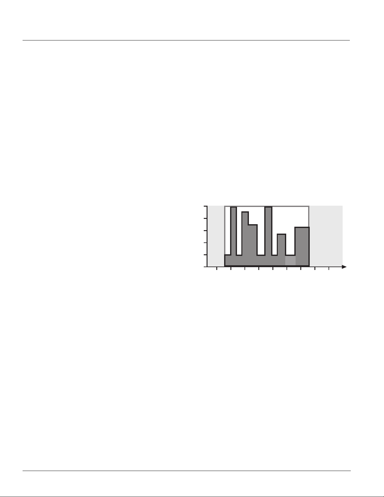
• Demand Control Ventilation By using CO2 levels to
monitor the actual occupancy pattern in a room, the
system can allow code-specific levels of outdoor air to
be delivered when needed without costly overventilation during periods of low or intermittent
occupancy (
Figure 9. Energy Savings with Demand Control Ventilation
100%
20%
• Occupancy Mode Operation Units can be
programmed to operate only sparingly during
unoccupied periods and at night to conserve energy.
Figure 9).
Energy Savings
with DCV
Unoccupied
After Hours
DCV's fresh air for indoor air quality
6:00 8:00 10:00 12:00 2:00 4:00 6:00 8:00 10:00
School Hours
Cleaning
Unoccupied
10 McQuay Catalog 1600
Page 11

Features & Benefits
Easy To Maintain
AAF-HermanNelson Unit Ventilators are designed to
provide easy access for maintenance and service
personnel to all serviceable components. Most
maintenance tasks are easily handled by a single
person.
Modular Fan Deck
The entire fan deck is easily removed as a single unit.
This provides ready access to fan wheels, motors,
bearings and other components for service, cleaning or
repair.
The fan deck’s rotating element has one large, selfaligning, oilable end bearing and two oilable motor
bearings for smoother operation. The location of these
bearings at the ends of the shaft (out of the airstream)
enables easy access and long life.
Figure 10. Long-life bearings
Even “permanently” lubricated motors are supplied with
recommended lubrication charts calling for lubrication
every seven years. Maintenance instructions of the
motor manufacturer should be followed closely.
Heavy-Duty Discharge Grille
The discharge grille on the top of the unit is made from
extra-strength steel bar stock, promoting long life
(
Figure 11). It can be removed to facilitate cleaning of
fans and fan housings. A built-in 10-degree angle
provides proper air throw to blanket the room for proper
air circulation and comfort.
Figure 11. Heavy-Duty Steel Discharge Grille
Easy Motor Removal
Unlike with many competitive models, the motor in
AAF-HermanNelson unit ventilators is separate from the
fan assembly and is located out of the airstream at the
end of the fan shaft—away from the hot coil—for easier
maintenance and removal. Locating the motor away from
the coil (
motor life. Our direct-coupled motor and self-aligning
motor mount facilitate motor change-out. The motor
comes with a molex plug that fits all sizes and further
simplifies removal.
Figure 12) has the added benefit of extending
Figure 12. Modular Fan Deck
Heavy-Duty Discharge Grille
Modular Fan Deck
AAF-HermanNelson Model AV Unit Ventilators 11
Motor & Bearings Located
Out Of Airstream
Page 12
Features & Benefits
Tamper-Resistant Fasteners
Front panels and top access doors are held in place by
tamper-resistant, positive-positioning fasteners. They are
quickly removed or opened with the proper tool, but deter
unauthorized access to the unit’s interior (
Figure 13).
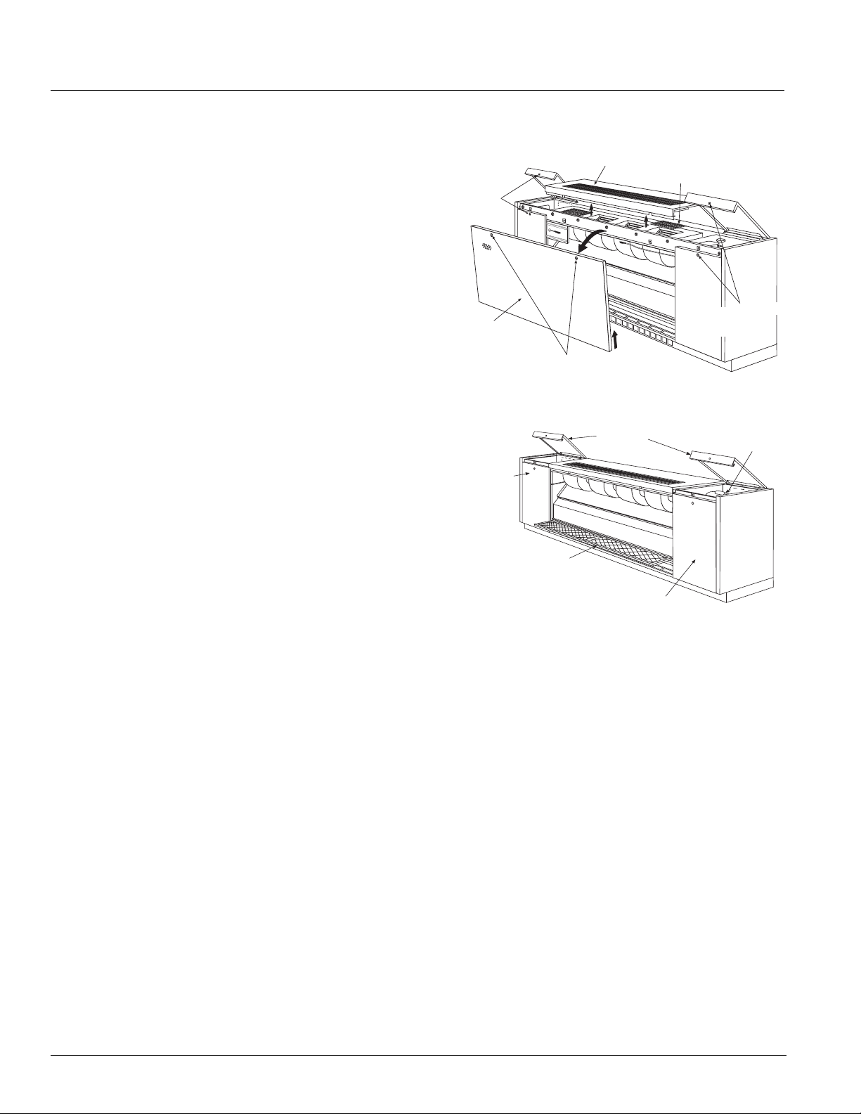
Sectionalized Access Panels And Doors
All floor units have three separate front panels and
hinged top access doors, sized for convenient handling
by a single person (
Figure 13). The result is easy,
targeted access to the component that needs servicing:
• Two 12 inch-wide end panels provide easy access to
piping, temperature control components and the fan
switch. Unlike units with full-length front panels, these
can be removed without disturbing the normal
operation of the unit.
• Hinged top access doors provide easy access into the
end compartments to facilitate convenient servicing of
the motor and shaft bearing.
• A short, center front panel provides easy access to the
filter and discharge grille.
Single-Filter Design
With AAF-HermanNelson’s single-filter design, filter
change-out takes only seconds. Uneven dust loading is
eliminated, which is common to units with separate filters
for room and outdoor air, or that use a metal partition to
separate filtering of indoor and outdoor air. The result
can be longer filter life, which means less maintenance
and fewer filters consumed.
Three filter types are offered:
• Single-use filters which feature Amerglas media and
are designed to be used once and discarded. These
are standard on all but electric heat units.
• Permanent metal filters which may be removed for
cleaning and reused numerous times. These are
standard on electric heat units.
• Renewable media filters, which consist of a heavyduty, painted-metal structural frame and renewable
Amerglas media.
Figure 13. Easy Access With Tamper-Resistant Fasteners
Discharge Grille
Doors
Right Front
Access Panel
Discharge Screen
Tamper-Resistant
Fasteners
Fan
Motor
Ta m pe r -
Resistant
Fasteners
Center Front Access
Panel
Tamper-Resistant
Fasteners
Top Access
Left Front
Access Panel
Renewable
Media Filter
12 McQuay Catalog 1600
Page 13

Features & Benefits
Built To Last
Our industrial-strength design provides the durability to
withstand the rigors of the classroom environment. Its
solid construction and rugged finish promotes continued
alignment, structural strength and long-lasting beauty
decades after the unit is installed. In fact, many units
installed over 30 years ago continue to provide quiet,
reliable classroom comfort.
Heavy Duty Frame Construction
AAF-HermanNelson’s exclusive, unitized frame
(
Figure 14) is far superior to the fastener-type
construction used by other manufacturers. Loosened
fasteners can cause vibration, rattles and sagging
panels. With unitized construction, there are no fasteners
(screws or bolts) to come loose.
Other design features that promote trouble-free
operation and long life include:
• A corrosion-resistant, galvanized-steel frame.
• Extra-strength, steel-bar discharge grille.
• Heavy-gauge-metal cabinet access panels and doors.
• An extra-strength pipe tunnel that stiffens the structure
while adding aerodynamic air flow within the unit.
• Hidden reinforcement that provides additional built-in
support for the top section as well as better support for
the fan deck assembly.
• A rigid exterior that is strong enough to support
maintenance personnel without fear of damaging the
unit.
Rugged Exterior Finish
The superior finish of the unit ventilator’s cabinets fosters
long-lasting beauty as well as resistance to abuse and
corrosion. We apply the very highest standards at every
step of the finishing process to provide lasting quality:
• High-quality furniture steel is carefully inspected before
painting. Scratches and marks that might show through
are removed.
• After fabrication, the metal undergoes a five-stage
cleaning and phosphatizing process to provide a good
bonding surface and reduce the possibility of peeling
or corrosion.
• A specially formulated, environmentally friendly,
thermosetting urethane powder is applied
electrostatically to the exterior panels. This film is
oven-cured to provide correct chemical cross-linking
and to obtain maximum scuff- and mar-resistance.
• The top of the unit is finished with a textured, non-glare
and scuff-resistant, charcoal bronze electrostatic paint.
End and front panels are available in a pleasing array
of architectural colors.
• The Oxford brown steel kickplate is coated and baked
with a thermosetting urethane powder paint to blend
with floor moldings and provide years of trouble-free
service.
• Each unit is painstakingly inspected before boxing,
then encapsulated in a clear plastic bag, surrounded
by an extra-heavy-duty cardboard box and secured to
a skid to help provide damage-free shipment.
Figure 14. Heavy-Duty, Welded Chassis
Unitized Frame
Welded
Construction
AAF-HermanNelson Model AV Unit Ventilators 13
Energy-Efficient
Fan Motor
Page 14
Features & Benefits
Durable, Energy Efficient Fan Motors
AAF-HermanNelson unit ventilators are equipped with
115/60/1 NEMA motors that feature low operating current
and wattage (
Figure 15. Energy-Efficient Fan Motor
Additional features of these motors include:
• Split-capacitor (PSC) design with automatic reset and
thermal-overload protection.
• No brushes, contacts or centrifugal starting switches—
the most common causes of motor failure.
• A built-in, decoupled isolation system to reduce
transmission of vibrations for quieter operation.
• A multi-tap, auto-transformer (Figure 16) provides
multiple fan motor speed control through the speed
switch. The motor is independent of supply voltage,
which allows stocking of one motor (school districtwide) for various voltage applications.
Figure 16. Multi-Tap Auto-Transformer
Figure 15).
Energy Efficient
NEMA Motor
Decoupled Isolation
System
Additional features include:
• Face and bypass dampers have a twist-free
reinforced aluminum construction for durability.
Aluminum is used because it is lightweight and
noncorrosive, resulting in low torque and easy
movement.
• Outdoor air dampers are made of galvanized steel to
inhibit corrosion, with double-wall welded construction
for rigidity and encapsulated insulation (
Figure 17).
Additional insulation is provided on the exterior of the
outdoor air damper blade and on the outdoor air entry
portion of the unit.
Figure 17. Outdoor Damper Seals Out Cold Weather
Turned Metal
Damper Blade
Turned Metal
Damper Stop
Wool Mohair
End Seal
Full-Length
Wool Mohair Damper
Additional
Insulation
Wool Mohair End
Seal
• Room air dampers are free-floating and designed to
prevent intermittent gusts of cold air from blowing
directly into the classroom on windy days (
Figure 18).
They are constructed of aluminum with built-in rigidity.
The metal forming technique that is employed resists
twisting and incorporates a full-length counter weight
for easy rotation. The simple principle of an area
exposed to a force is used to automatically close the
damper, rather than open it, when gusts of cold air
occur.
Figure 18. Room Air Damper Auto-Closed By Wind Gusts
Wind
Gust
Durable Damper Design
All dampers in AAF-HermanNelson Unit Ventilators use
the turned-metal principle on their long closing edges
(
Figure 17). Positive sealing is provided by embedding
the edge into wool mohair (no metal to metal contact).
There are no plastic gaskets to become brittle with time,
sag with heat or age, or require a difficult slot fit to seal.
Nylon damper bearings foster quiet, maintenance-free
operation.
14 McQuay Catalog 1600
Page 15
MicroTech II Controls
MicroTech II Controls
MicroTech II Controls For Superior Performance, Easy Integration
AAF-HermanNelson unit
ventilators equipped with
MicroTech
provide superior performance
and easy integration into your
building automation system of
choice. MicroTech II benefits
include:
• Factory integrated and tested
controller, sensor, actuator and unit options promote
quick, reliable start-up and minimize costly field
commissioning.
• High-performance features and advanced control
options can quickly pay for themselves in saved energy
costs and more comfortable classrooms.
• Select from three control levels: stand-alone, masterslave or network control.
• For network control applications, our Protocol
Selectability feature provides easy, low-cost integration
of AAF-HermanNelson unit ventilators into most
building automation systems.
• Flexible BAS network communication options guard
against controls obsolescence, keeping MicroTech II
controls viable for the life of your AAF-HermanNelson
equipment.
II unit controllers can
If a school has more than one zone, separate, remote
time clocks are used to regulate each zone. In this case,
the remote-mounted time clock energizes or deenergizes an external, 24-volt or 120-volt control circuit
which operates the unit-mounted day/night relays in that
zone.
Master-Slave Control
Designate the master and slave units and we will factory
configure and install the controllers so they are set up for
a local peer-to-peer network between units (leaving only
the network wiring between these units to be field
installed).
Slave units can be field-configured to be dependent or
independent as follows:
• Dependent slave units follow the master unit
completely. They are ideal for large spaces that have
even loads across the space (such as some libraries).
• Independent slave units (default) use master setpoints
and slave sensors. The slave follows the master unit
modes, such as heat or cool, but has the flexibility to
provide the conditioning required for its area within the
space. Independent slave units perform better in
spaces where loads vary from one area of the space to
the other (such as stairwells or cafeterias).
Three Control Levels
MicroTech II unit controllers provide the flexibility to
operate AAF-HermanNelson unit ventilators on any of
three levels:
• As stand-alone units, with control either at the unit or
from a wall sensor.
• In a master-slave relationship, where slave units follow
the master unit for some or all functions.
• Controlled as part of a network using a centralized
building automation system.
Stand-Alone Control
When operating in stand-alone mode, the MicroTech II
controller performs complete room temperature and
ventilation control. Units can be operated in occupied,
unoccupied, stand-by, or bypass (tenant override)
modes. Occupied/unoccupied changeover can be
accomplished:
• Manually by a unit-mounted day/night switch.
• Automatically by a unit-mounted day/night time clock.
• Automatically by a remote-mounted time clock that
operates unit-mounted day/night relays.
Network Control
MicroTech II unit controllers provide easy integration into
your building automation system of choice. All factoryinstalled options are handled by the unit controller. This
simplifies the transmission of monitoring and setpoint
data to the building automation system.
You select BACnet, LonTalk or Metasys N2 Open
communications to communicate control and monitoring
information to your BAS, without the need for costly
gateways (see
page 22). Unit controllers are LONMARK certified with the
optional LONWORKS communication module.
Flexible network communication options via our Protocol
Selectability feature help you avoid control obsolescence
over the life of your AAF-HermanNelson equipment.
“Optional Communication Modules” on
AAF-HermanNelson Model AV Unit Ventilators 15
Page 16
MicroTech II Controls
A Wide Variety of Input, Output & Alarm Data Points Available
A wide variety of data is available from AAFHermanNelson unit ventilators when equipped with
MicroTech II unit controllers in a network situation. They
classroom and notify your building automation system of
alarm conditions regardless of the protocol you select.
See
"Table 3: Network Operation - Typical Data Points"
below for a list of inputs, outputs and alarm functions
available.
provide a clear picture of just what's happening in each
Table 3: Network Operation - Typical Data Points
Read/Write Attributes Read Only Attributes
• Application Mode
• Auxiliary Heat
Enable
• Compressor
Enable
• Emergency
Override
• Energy Hold Off
• Heat/Cool Mode
• Occupancy
Override
• Outdoor Air
Humidity
• Reset Alarm
• Reset Filter Alarm
• Setpoint Offset
• Source (Water In)
Temperature
• Space CO2
• Space Humidity
• Space
Temperature
• Binary Input 1 Status
• Binary Output 1 Status
• Binary Output 2 Status
• Compressor Run Time
• Chiller Water Valve
Position
• Discharge Air
Temperature
• Discharge Air
Temperature Setpoint
• Effective Setpoint
• Effective Space
Temperature
• Fan Speed
• F & BP Damper
Position
• Local Setpoint
• Outdoor Air Damper
Position
• Space Fan Runtime
• Unit Ventilator
Controller State
• Water-out Temperature
• WH or CW/HW Valve
Position
1.
Not all data points or alarms listed will be available in all unit ventilator configurations. Humidity and CO2 points require the use of optional sensors.
1
Read/Write
Setpoint Attributes
• Econ. IA/OA Enthalpy
Differential Setpoint
• Econ. IA/OA Temp.
Differential. Setpoint
• Econ. Outdoor Air
Enthalpy Setpoint
• OAD Min. Position
Low-Speed Setpoint
• OAD Min. Position
Med.-Speed Setpoint
• Occupied Cooling
Setpoint
• Occupied Heating
Setpoint
• Space CO2 Setpoint
• Space Humidity
Setpoint
• Standby Cooling
Setpoint
• Unoccupied Cooling
Setpoint
• Unoccupied Heating
Setpoint
• UV Software
Application Version
Typical Alarms
• Indoor Air Temperature Sensor
Failure
• DX Pressure Fault
• Compressor Envelope Fault
• Condensate Overflow Indication
• Indoor Air Coil DX Temperature
Sensor Failure
• Outdoor Air Temperature Sensor
Failure
• Discharge Air Temperature Sensor
Failure
• Outdoor Air Coil DX Temperature
Sensor Failure (or)
• Water Coil DX Temperature
Sensor Failure
• Water-out Temperature Sensor
Failure (or)
• Water-in Temperature Sensor
Failure
• Space Humidity Sensor Failure
• Outdoor Humidity Sensor Failure
• Space CO2 Sensor Failure
• Source Temperature (Water-in)
Inadequate Indication
• Change Filter Indication
16 McQuay Catalog 1600
Page 17

MicroTech II Controls
Control Modes and Functions
AAF-HermanNelson unit ventilators equipped with
MicroTech
operate in a variety of modes based on the current
situation in the room and the status of the unit ventilator.
Changes in mode can be triggered manually, via network
signals, by sensor readings, or by date and time.
External inputs and outputs can be used to change
modes, communicate data to network controls or change
the functional operation of the unit.
Occupancy Modes
MicroTech II unit controllers can be set up to change
modes based on room occupancy. Four different
occupancy modes are provided, as described below.
Occupied Mode
This is the normal daytime operation mode. The
controller maintains a room set point using the outside air
capability and other functions.
Note: For non-school applications, the unit can also be
Unoccupied Mode
This is the night setback operating mode, in which the
unit responds to a new room set point and cycles to
maintain the condition. The fan comes on when heating
or cooling is needed and runs until the load is satisfied.
The outdoor air damper is closed during this mode.
When a cooling load is satisfied by a refrigerant system,
the compressor is de-energized and the unit ventilator
indoor fan continues to run for a fixed period of time to
remove coldness from the evaporator coil. This reduces
the potential for low refrigerant temperatures to exist on
the evaporator coil.
II unit controllers can be programmed to
configured to cycle the fan in response to the room load.
In this case, the fan would normally be in the Off Mode
until heating or cooling is required. The outside air
damper is always closed when the fan is off. When the
fan starts, the outside air damper opens to the required
position, usually minimum position.
can be made in 1-minute increments from 1 minute to
240 minutes through ServiceTools™ (see
network.
page 24) or a
Economizer Modes
Economizer operation is facilitated by the outdoor air
damper, which automatically adjusts the above-minimum
outside air position to provide free cooling when the
outdoor air temperature is appropriate. Three levels of
economizer control are available:
Basic Economizer Operation: The MicroTech II
controller compares the inside and outside temperatures.
If the temperature comparison is satisfactory, then freeair economizer operation is used to cool the space.
Reheat units also come configured with an indoor
humidity sensor.
Expanded Economizer Operation: In addition to
comparing inside and outside temperatures, outdoor
relative humidity is measured to calculate outside air
enthalpy. If the enthalpy set point is not exceeded, and
the temperature comparison is satisfactory, then free
economizer operation is used to cool the space. This
helps to minimize the entrance of humid outside air.
Leading-Edge Economizer Operation: The MicroTech II
controller compares both indoor and outdoor
temperatures and indoor and outdoor relative humidities.
Then it calculates both inside and outside air enthalpy to
determine if free economizer operation can cool the
space with non-humid outside air. This is a true enthalpy
economizer—a first for unit ventilators.
Night Purge Mode
Under this mode, the unit is configured to purge the room
space for one hour for various reasons (odor or fume
removal, drying, etc.).During Night Purge the outside air
damper is open full and the fan is run on high speed. No
“normal” heating or cooling takes place (the emergency
heat set point is maintained) and the exhaust fan, if the
room is so equipped, is signaled to turn on.
Stand By Mode
In this mode, the unit maintains the occupied mode set
point temperature with the outdoor air damper closed.
The fan runs continuously unless it is configured to cycle
in response to the load.
Bypass Mode
This is a tenant override operating mode in which the unit
is placed back into the Occupied Mode for a
predetermined time. The default is 120 minutes. Settings
AAF-HermanNelson Model AV Unit Ventilators 17
Freeze Prevention Mode
This mode helps protect the unit ventilator from freezing
air conditions. Control functions vary depending on the
type of temperature control used by the unit, as follows:
Face and bypass control units: Upon sensing a potential
freezing air temperature condition leaving the heating
coil, the unit will automatically protect itself by shutting
the outside air damper and opening the EOC valve. The
face and bypass damper is allowed to operate normally
to control the space. The fan continues to run to remove
the cold air. Once accomplished, the freezestat is reset,
Page 18

MicroTech II Controls
the outside air damper opens to the minimum position
and the unit commences its normal mode of operation.
Valve control units: Upon sensing a potential freezing
air temperature condition leaving the heating coil, the
unit will automatically protect itself by shutting the outside
air damper and opening the hot water valve to a
minimum of 50% (more if required to heat the room). The
fan speed will be staged down to low speed and then
turned off. When the freezestat is reset, the outside air
damper opens to the minimum position and the fan runs
at low speed for a minimum of 10 minutes. It then will
stage up if needed to satisfy the room set point. This
reduces the potential to overheat a room recovering from
a potential freeze condition.
Note: Valve selection and coil sizing is critical for proper
operation. Face and bypass control is recommended for
proper humidity and freeze protection.
Emergency Heat Mode
If the unit is left in a mode that does not normally allow
heating (such as Off, Fan Only, Cool, or Night Purge)
and the room temperature falls below 55°F, the unit will
heat the space to above 55°F and then return to the
previously set mode of operation. This mode of operation
can be field configured and/or be disabled.
External Input Functions
The unit ventilator controller is provided with three (3)
binary inputs that allow a single set of dry contacts to be
used as a signal to it. Input signal choices are described
below. Multiple units can be connected to a single set of
dry contacts.
Note: Not all of the functions listed can be used at the same
time. The unit ventilator controller is provided with
configuration parameters that can be adjusted to select
which function will be used for these inputs where
multiple functions are indicated below. For wiring
examples see installation manual IM
Unit Ventilator Controller.
Unoccupied Input Signal
This input signals the unit ventilator controller to go into
unoccupied or occupied mode. When the contacts close,
the unit ventilator controller goes into unoccupied mode;
when the contacts open, it goes into occupied mode.
Additional variables can affect occupancy mode and
override this binary input. See
“Occupancy Modes” on
page 17.
Dewpoint/Humidity Input Signal (Optional)
This input signals the unit ventilator controller to go into
active dehumidification mode. When the contacts close
747: MicroTech II
(high humidity) the controller will go into active
dehumidification; when the contacts open (low humidity)
it will stop active dehumidification.
Remote Shutdown Input Signal
This input signals the unit ventilator controller to go into
shutdown mode. When the contacts close, the controller
goes into shutdown mode; when the contacts open, it
returns to normal operation.
Ventilation Lockout Input Signal
This input signals the unit ventilator controller to close
the outdoor air damper. When the contacts close
(ventilation lockout signal) the controller closes the
outdoor damper; when the contacts open, it returns to
normal outdoor damper operation.
Exhaust Interlock Input Signal
This input signals the unit ventilator controller that an
exhaust fan within the space has been energized. The
controller then repositions the outdoor air damper to a
user-adjustable minimum position. When the contacts
close (exhaust fan on signal) the controller uses the
value defined by the Exhaust Interlock OA Damper Min
Position Setpoint as the new minimum outdoor air
damper position regardless of the indoor air fan speed.
When the contacts open, it returns to normal outdoor
damper operation.
External Output Functions
The unit ventilator controller is provided with three (3)
binary outputs to perform the functions described below.
These are relay type outputs that are intended to be
used with signal level voltages only (24 VAC max).
Note: Not all of the functions listed can be used at the same
time. The unit ventilator controller is provided with
configuration parameters that can be adjusted to select
which function will be used for these outputs when
multiple functions are indicated below. For wiring
examples, see installation manual IM
Unit Ventilator Controller.
Lights On/Off Signal
This relay output provides one set of NO dry contacts
that can be used to signal the operation of the room
lights. When the unit ventilator controller is in occupied,
standby or bypass occupancy modes, the relay output
will signal the lights on (contacts closed); when the
controller is in unoccupied occupancy mode the relay
output will signal the lights off (contacts open).
747: MicroTech II
18 McQuay Catalog 1600
Page 19

MicroTech II Controls
Fault Signal
This relay output provides NO, NC, and Common
connections that can be used to signal a fault condition.
When a fault exists, the unit ventilator controller
energizes this relay output. When the fault or faults are
cleared, it de-energizes this relay output.
Exhaust Fan On/Off Signal
This relay output provides one set of NO dry contacts
that can be used to signal the operation of an exhaust
fan. When the outdoor air damper opens more than the
Energize Exhaust Fan OA Damper Setpoint, the relay
output will signal the exhaust fan on (contacts closed).
When the outdoor damper closes below this setpoint, the
relay output will signal the exhaust fan off (contacts
open).
Auxiliary Heat Signal
This relay output provides one set of NO dry contacts
that can be used to operate an auxiliary heat device. The
unit ventilator controller by default is configured to
operate a NO auxiliary heat device (de-energize when
heat is required) such as a wet heat valve actuator with a
spring setup to open upon power failure. However, the
Auxiliary Heat Configuration variable can be used to set
the controller to use an NC auxiliary heat device
(energize when heat is required) such as electric heat.
fan operation under normal operating conditions, in
conjunction with our GentleFlo fan technology (see
5page 5) contributes to a very quiet classroom
envionment.
page
Demand-Controlled Ventilation (Optional)
AAF-HermanNelson unit ventilators can be equipped to
use input from a CO
based on actual occupancy instead of a fixed design
occupancy. This Demand Controlled Ventilation (DCV)
system monitors the amount of CO
students and teachers so that enough fresh outdoor air is
introduced to maintain good air quality. The system is
designed to achieve a target ventilation rate (e.g., 15
cfm/person) based on actual occupancy.
By using DCV to monitor the actual occupancy pattern in
a room, the system can allow code-specific levels of
outdoor air to be delivered when needed. Unnecessary
over-ventilation is avoided during periods of low or
intermittent occupancy.
With DCV you can be confident that your school is
meeting ventilation standards for Indoor Air Quality and
that your students are receiving adequate air to be
attentive to instruction. At the same time, you are saving
money in early morning hours, in between classes, or
after hours when classrooms are heated and cooled but
not always fully occupied.
controller to ventilate the space
2
produced by
2
Advanced Control Options
MicroTech II controls make possible a number of
advanced control options that can quickly pay for
themselves in saved energy costs and more comfortable
classrooms, as described below.
Part Load Variable Air Control
Part Load Variable Air control can be used in conjunction
with face and bypass damper temperature control to
automatically adjust the unit ventilator fan speed based
upon the room load and the room-temperature PI control
loop. This MicroTech II control option provides higher
latent cooling capabilities and quieter operation during
non-peak load periods by basing indoor fan speed upon
room load.
During low-load or normal operation (about 60% of the
time) the fan will operate on low speed. When the load
increases to an intermediate demand, the fan will
automatically shift to the medium-speed setting. Under
near-design or design-load conditions, the fan will
operate on high speed. A built-in, 10-minute delay helps
minimize awareness of fan speed changes. Low-speed
As Simple as a Thermostat
Demand Controlled Ventilation is easy to apply. When
DCV is ordered, a CO
and configured for operation. The system does the rest.
If desired, the ventilation control setpoint can be adjusted
through the MicroTech II Controller.
sensor is mounted on the unit
2
Acceptance By Codes And Standards
ASHRAE Standard 62-2004 Ventilation for Indoor Air
Quality recognizes CO
controlling ventilation based on occupancy. The
ASHRAE standard has been referenced or adopted by
most regional and local building codes. This standard
references ventilation on a per-person basis.
Using CO2 control will sometimes lower the absolute
amount of outside air delivered into a room but will
maintain the per-person rate. For example, if a
classroom is designed for 30 students, the ventilation
rate is 450 cfm (30 students X 15 cfm/student). However,
when there are only ten students in the classroom, the
CO
control will adjust ventilation to 150 cfm (10 students
2
X 15 cfm/student). A minimum base ventilation rate
(typically 20% of design levels) is provided when in the
based DCV as a means of
2
AAF-HermanNelson Model AV Unit Ventilators 19
Page 20

MicroTech II Controls
occupied mode. This provides outdoor air to offset any
interior source contamination while allowing for proper
space pressurization.
Active Dehumidification Control (Reheat)
In high-humidity applications where valve-controlled,
reheat units are used, the Active Dehumidification
Control (ADC) sequence should be considered. During
excessive humidity conditions, a humidity sensor directs
the unit to continue cooling past the room setpoint to
remove excess moisture. Hydronic heat or electric heat
is then used to reheat the discharge air to maintain
acceptable room temperatures.
MicroTech II controls minimize the amount of reheat
needed to maintain relative humidity below a preset limit.
Reheat is used only when required and in the most
energy-efficient manner possible.
Active Dehumidification comes standard on units
equipped with MicroTech
configuration and valve-control temperature modulation.
The MicroTech ADC humidity sensor is unit-mounted. It
issues a signal proportional to the classroom’s humidity
level (unlike humidistats which issue an open-close
signal). This enables a control sequence that manages
both the temperature and the relative humidity.
When the relative humidity exceeds a preset value, the
modulating chilled-water valve opens fully to dehumidify
the mixture of outdoor and return air entering the cooling
coil. The reheat modulating water valve then opens, or
electric heat is engaged, to reheat the air leaving the
cooling coil, as required to maintain the classroom
setpoint.
Active dehumidification starts when the indoor relative
humidity exceeds the preset relative humidity upper
setpoint and continues until the room humidity falls 5%
below the endpoint. During active dehumidification,
economizer operation is disabled (and the outdoor air
damper is reset to its minimum position) unless the
outdoor air temperature is below 55°F. It is maintained
until dehumidification is completed. When the indoor
humidity level is satisfied, the MicroTech II controller
reverts to its normal sequences to satisfy the classroom
temperature setpoint.
II controls, a reheat
closer contact with the cold coil for passive
dehumidification.
This only occurs in the unoccupied mode as the unit
operates to satisfy the humidity set point with the outside
damper closed. The face and bypass damper is placed in
a minimum face position to promote high latent cooling.
The unit fan continues to operate on low speed until the
load is satisfied. This is very helpful in high humidity
areas where high night time humidity can be absorbed in
the building during off hours.
DX Split System Control
On unit ventilators equipped with direct-expansion (DX)
coils, the unit ventilator controller is configured to operate
the compressor as secondary (mechanical) cooling when
economizer cooling is available, and as primary cooling
when economizer cooling is not available. Addtiional DX
control features include:
Compressor Envelope: This helps protect the
compressor from adverse operating conditions that can
cause damage and or shortened compressor life. It ends
compressor operation if coil temperatures exceed the
defined operating envelope.
Compressor Cooling Lockout: The unit ventilator
controller is configured to lock out compressor cooling
when the outdoor air temperature falls below the
compressor cooling lock out setpoint. Below this
temperature setpoint only economizer cooling will be
available.
Minimum On And Off Time: The unit ventilator controller
is provided with minimum-on and minimum-off timers to
prevent adverse compressor cycling (3-minutes default).
Compressor Start Delay Variable: This variable is
intended to be adjusted as part of the start-up procedure
for each unit. It is used to prevent multiple unit
compressors from starting at the same time after a power
failure or after an unoccupied-to-occupied changeover.
Each unit should be configured at start-up with a slightly
different (random) delay, or groups of units should be
provided with different delays.
Passive Dehumidification Control
On units with face and bypass damper control, a chilledwater coil and MicroTech II part-load variable air control,
passive dehumidification can be used under high
humidity conditions to keep classrooms comfortable. A
unit-mounted humidity sensor and a low fan speed are
utilized to improve latent cooling by keeping the air in
20 McQuay Catalog 1600
Page 21

MicroTech II Controls
System Components
The main components of the MicroTech II system are:
• The Unit Ventilator Controller (UVC)
• The Local User Interface (LUI)
• Optional plug-in network communication modules
In addition, unit ventilators equipped with MicroTech II
controllers feature factory-mounted sensors and
actuators for system control and feedback.
Unit Ventilator Controller
The MicroTech II UVC is a DDC, microprocessor-based
controller designed to provide sophisticated comfort
control of an economizer-equipped AAF-HermanNelson
unit ventilator. In addition to normal operating control, it
provides alarm monitoring and alarm-specific component
shutdown if critical system conditions occur. Each UVC is
factory wired, factory programmed and factory run-tested
for the specific unit ventilator model and configuration
ordered by the customer.
Figure 19. MicroTech II Control Board
Terminal Connections
Plug-In Control Module
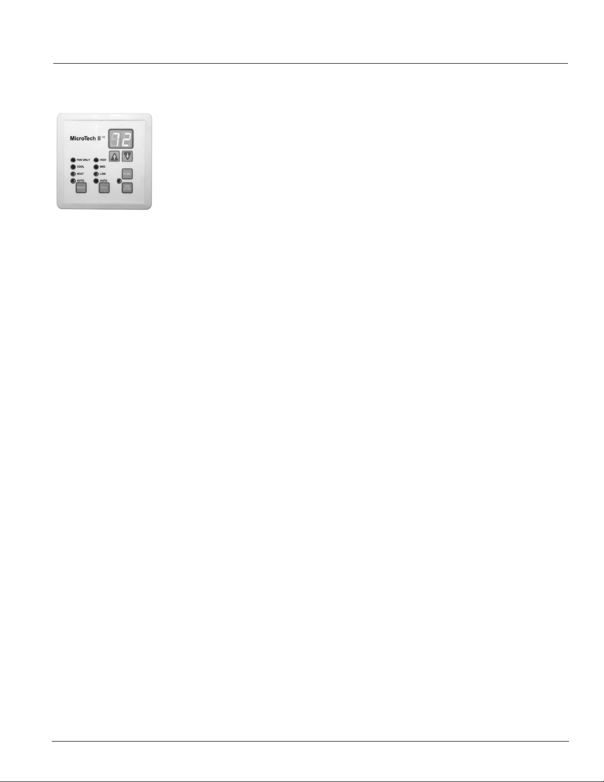
Figure 20. User Interface Touch Pad
The User Interface has individual touch-sensitive printed
circuit board mounted buttons, and comes with a built-in
menu structure (Hidden Key and Password Protected) to
change many of the common operating variables.
Four Operating Mode States
Four different user operating mode states can be chosen
on the LUI:
Heat: Heating and economizer operation only.
Cool: Cooling and economizer operation only.
Fan Only: Fan only operation.
Auto: The unit automatically switches between heating,
cooling and economizer operation to satisfy the room
load conditions. The current unit state is also displayed.
Local User Interface
A built-in LUI touch pad with digital LED Display is
located in the right hand compartment below the top right
access door. In addition to the Operating Mode States
and Fan Functions, the Touch Pad will digitally display:
• The room set point temperature.
• The current room temperature.
• Any fault code for quick diagnostics at the unit.
Four Fan States
Four fan states are provided on all units: high, medium
low and Auto speed modulation. The Auto speed
function (part load, variable air) varies the fan speed
automatically to meet the room load whether the unit is in
heating, cooling or economizer mode.
All this is accomplished with a standard, single-speed
NEMA frame motor. A built-in 10-minute delay helps
minimize awareness of speed changes. During low-load
or normal operation (about 60% of the time) the fan will
operate at low speed. The low speed operation, along
with GentleFlo fan technology, contributes to a very quiet
classroom environment.
When the load increases to an intermediate demand, the
fan automatically shifts to the medium speed setting. At
near-design or design-load conditions the fan will
operate on high speed.
With four fan states and GentleFlo fan technology, there
is no need to oversize units or worry about
uncomfortable conditions.
AAF-HermanNelson Model AV Unit Ventilators 21
Page 22

MicroTech II Controls
Optional Communication Modules
Optional communication modules provide control and
monitoring information to your building automation
system without the need for costly gateways. Available
communication protocols include BACnet, LonTalk and
Metasys N2 Open. The communication modules for each
are described below.
Figure 21. Typical 2" x 4" Communication Module
BACnet MS/TP Communication Module
This module allows the UVC to inter-operate with
systems that use the BACnet (MS/TP) protocol with a
conformance level of 3. It meets the requirements of the
ANSI/ASHRAE 135-1995 standard for BACnet systems.
LonWorks SCC Communication Module
This module supports the LonWorks SCC (Space
Comfort Communication) profile number 8500-10. Unit
controllers are LonMark certified with this optional
LonWorks communication module.
Metasys N2 Communication Module
This module provides N2 Open network communication
capability to the UVC for communication with Johnson
Metasys systems.
Figure 22. Wall-Mounted Temperature Sensors
Standard Expanded Deluxe
Standard Sensor: This sensor has no remote setpoint
adjustment capability.
Expanded Sensor: This sensor has a remote room
setpoint adjustment of ±3°F (±1.5°C) from the room
setpoint established on the unit ventilator’s local user
interface touch pad. Five temperature settings are
provided on each side of center.
Deluxe Sensor : This sensor has a remote room setpoint
adjustment of from 54°F (12°C) to 82°F (28°C) with a
midpoint setting of 68°F (20°C).
Note: McQuay does not recommend using the Deluxe Sensor
with DX systems due to its wide operating range and
potential problems with the refrigerant system.
Humidity Sensors
On units equipped with humidity sensors, the UVC is
configured to use a 0-100% RH, 0
VDC, capacitive
humidity sensor. Humidity sensors are available as unitmounted only. The humidity sensors are used with units
capable of passive or active dehumidification, or with
units using an outdoor enthalpy economizer or an indoor/
outdoor enthalpy economizer.
Sensors
The UVC is configured to use passive Positive
Temperature Coefficient (PTC) unit-mounted and wallmounted sensors. These sensors vary their input
resistance to the UVC as the sensed temperature
changes.
CO2 Sensor for Demand Controlled Ventilation
On units equipped for Demand Controlled Ventilation
(DCV) the UVC is configured to use a 0-2000 PPM, 0-10
VDC, single beam absorption infrared gas sensor. CO
2
sensors are available as unit mounted only. An air
collection probe (pitot tube and filter) is installed in the
return air of the unit.
Remote Wall-Mounted Temperature Sensors
MicroTech II unit ventilators offer three choices for
Figure 23. CO2 Sensor For Demand Control Ventilation
remote wall-mounted room sensors (
Figure 22). Each
has a tenant override capability and comes with an
international, quick-fastening connection capability.
22 McQuay Catalog 1600
Page 23

MicroTech II Controls
Figure 24. MicroTech II Sensor and Component Locations
Top V i ew
Room Humidity
Sensor (Optional)
Face & Bypass
Damper Actuator
RoomTemp
Outdoor/Return
Air Damper
Actuator
Sensor
Discharge Air
Temp S e n s o r
Interface (LUI)
External Signal
Connection Plugs
Freezestat
Low Refrig
Temp S n s r
Local User
Time Clock (Stand
Alone Unit Option)
Tenant Override
Switch
MicroTech II Unit
Ventilator Controller
Communication
Module (Optional)
Control Transformer
Fuse(s)
Electric
Connection Box
Outdoor Air
Temp S e n s o r
Outdoor
Humidity Sensor
Front View
Drainpan Condensate Overflow Sensor (Optional)
A sensor can be installed in the drain pan of the unit
ventilator to sense high water levels and force the unit to
discontinue cooling. This helps prevent the overflow of
condensate fwhen the drain is clogged.
Actuators
Face & Bypass Damper Actuator
On units equipped with face & bypass damper control,
the UVC is configured to operate a floating-point (tristate), direct-coupled, face & bypass damper actuator. To
determine the modulating damper position, the controller
uses a separate, factory-preset, configurable setting for
each actuator's stroke time. To increase accuracy, the
controller has an overdrive feature for the 0% and 100%
positions and a periodic (12-hour) auto-zero PI control
loop for each modulating actuator.
Figure 25. Face & Bypass Damper Actuator
CO2 Sensor
(Optional)
Main Power
On/Off Switch
Outdoor Air/Return Air Damper (OAD) Actuator
The UVC is configured to operate a floating-point (tristate) direct-coupled actuator for the outdoor air damper.
This actuator provides spring-return operation upon loss
of power for positive close-off of the outdoor air damper.
To determine damper position, the UVC uses a separate,
factory-preset, configurable setting for each actuator's
stroke time. To increase actuator positioning accuracy,
the UVC is provided with an overdrive feature for the 0%
and 100% positions and a periodic (12- hour) auto-zero
PI control loop for each modulating actuator.
Figure 26. Outdoor Air Damper Actuator
2-Position End-of-Cycle Valve Actuators (Optional)
On units equipped with 2-way or 3-way, end-of-cycle
(EOC) valves, the UVC is configured to operate 2position End-Of-Cycle (EOC) valve actuators
(
Figure 27). Spring return actuators are used for all End
of Cycle (EOC) valves. All wet heat and heat/ cool EOC
valves are normally open, and all cooling EOC valves
are normally closed.
AAF-HermanNelson Model AV Unit Ventilators 23
Page 24

MicroTech II Controls
Figure 27. End of Cycle Valve Actuator
Modulating Valve Actuators (Optional)
On units equipped with modulating valves, the UVC is
configured to operate floating-point (tri-state) actuators
for modulating 2- way and 3-way valves (
Figure 28. Modulating Valve Actuators
2-Way Valve 3-Way Valve
Figure 28).
Spring return actuators are used for all modulating
valves. All wet heat and heat/ cool valves are normally
open, all cooling valves are normally closed.
To determine modulating valve position the UVC uses a
separate factory preset, configurable setting for each
actuator's stroke time. For accuracy of actuator
positioning, the UVC is provided with an overdrive
feature for the 0% and 100% positions and a periodic
(12-hour) auto-zero PI control loop for each modulating
actuator.
Optional Time Clock For Stand-Alone Operation
As an option, stand-alone, non-slave unit ventilators can
be factory-equipped with a unit-mounted, digital, 24-hour/
7-day time clock with 20 programs (
is factory-wired to automatically place the unit into
occupied or unoccupied mode based upon its schedule.
Features of this clock include:
Figure 29). The clock
• Large keys with circular programming for easy
schedule setup
• An LCD display
• Manual 3-way override (On/Auto/Off)
• Capacitor backup to retain program memory during
power outages.
Figure 29. Optional Time Clock
ServiceTools™
ServiceTools for MicroTech II Unit Ventilators is a CD
containing software for operation on a personal
computer. This software provides a visual schematic of
the unit, a pictorial representation of the sequence of
operation and enables the service technician to:
• Monitor equipment operation.
• Configure network communications.
• Diagnose unit operating problems.
• Download application code and configure the unit.
This software is a purchased tool for service technicians
and will run on PCs with Windows
2000 (SP2), and NT4.0 (SP6) and XP (SP1) operating
systems. This tool provides more capabilities than the
unit’s user interface touch pad and is highly
recommended for startup and servicing. (It may be
required for startup and/or servicing, depending upon
unit integration and other requirements.) It has no BAS
functions, such as scheduling or trending, and it cannot
serve as a Work Station Monitoring package.
ServiceTools comes with a service cable having two
interface connections:
• A 12-pin connection to connect to the main control
board.
• A 3-pin connection to connect to the optional
communication modules.
®
98 (Second Edition),
24 McQuay Catalog 1600
Page 25

Accessories
Accessories
Wall Louvers & Grilles
AAF-HermanNelson wall louvers allow outdoor air to be
drawn in while blending with the building architecture.
They are sized to match the unit outside air opening and
provide maximum air intake. Heavy-gauge, all-aluminum
construction is standard, with a decorative grille optional.
Both louvers and grilles are available either painted or
unpainted. When painted, a specially formulated,
environmentally friendly thermosetting urethane powder
is applied electrostatically and baked for long lasting
beauty as well as resistance to corrosion. The paint is
then oven cured to provide correct chemical crosslinking, which can provide years of service. The alloy
used for louvers and grilles, AQ 5005, is suitable for color
anodizing by others.
Figure 30. Intake Louvers
Horizontal Blade Louver
Vertical Blade Louver
Weep Holes
Louver Details
Louvers are available in both horizontal and vertical
blade configurations (
Figure 30):
• Horizontal blade construction turns the incoming air
to keep moisture from entering. Bottom weep holes
drain moisture to the outside.
• Vertical-blade construction provides positive water
impingement and entrapment. The bottom lip drains
moisture to the outside.
Louvers can be supplied with or without flanges:
• Flanged louvers are typically used for a panel wall
finish (
Figure 31).
• Unflanged louvers are typically used for recessing
into a masonry wall.
A half-inch-square mesh bird screen (Figure 32) located
on the leaving air side of the louver prevents birds and
other small animals from entering. The screen’s strong
aluminum mesh is designed to minimize air pressure
drops, unlike expanded metal mesh.
Figure 32. Louver Assembly With Grille
Bird Screen
Louver
Grille
Grille Details
AAF-HermanNelson decorative intake grilles come in
either painted or unpainted AQ 5005 aluminum with
holes for mounting to building exteriors (
Figure 33). Their
square holes are designed to match the blades of the
AAF-HermanNelson louver, maximizing the air opening.
Figure 33. Decorative Intake Grille
Weep Holes
Figure 31. Flanged Louver (Indoor View)
Bird Screen
AAF-HermanNelson Model AV Unit Ventilators 25
Page 26

Accessories
Ventimatic™ Shutter Room Exhaust Ventilation
Outdoor air introduced by the unit ventilator must leave
the room in some way. In some states, exhaust vents are
required by law or code to accomplish this. The
Ventimatic shutter is a more economical solution to the
problem.
The Ventimatic shutter is a continuously variable, gravityactuated room exhaust vent (
Figure 34). It operates in
direct response to positive static air pressure created
when ventilation air is brought into the room by the unit
ventilator. It is a “one-way” shutter that opposes any flow
of air into the room.
Figure 34. Ventimatic Shutter
Front (Indoor Side)Back (Outdoor Side)
The Ventimatic Shutter’s ability to exhaust only the
amount of air required results in considerable energy
savings. In the heating mode, the unit ventilator will be
able to bring in only the required percent minimum
outdoor air. Unlike systems that rely on powered
exhaust, no energy will be wasted heating excess
outdoor air. In the cooling mode, the unit ventilator will be
able to bring in 100% outdoor air for full natural or free
cooling when it is energy effective.
Since it is not powered, Ventimatic Shutter’s operation is
inherently silent. Unlike other non-powered vents, it
opens at an extremely low positive pressure (0.005"). Its
shutter flaps are made of temperature-resistant glass
fabric impregnated with silicone rubber for flexibility and
long life. This fabric retains its original properties down to
-50°F.
Ventimatic Installation
The Ventimatic Shutter should be mounted on the same
wall as the unit ventilator. This neutralizes the effect of
wind pressure forcing excess air into the room through
the unit ventilator louver. That’s because the wind
pressure will also keep the Ventimatic Shutter closed and
prevent room air from escaping. Since the existing room
air cannot leave, excess air from the wind gust will not
enter. (In contrast, a powered exhauster would “assist”
the wind’s effect.) Same-wall mounting also minimizes
“short circuiting” of air flow that could occur with
opposite-wall mounting.
The Ventimatic Shutter is generally mounted on an AAFHermanNelson wall louver (ordered separately) which is
then used for exhaust (
Figure 35). For large unit
ventilators, two Ventimatic Shutters may be mounted
side by side on the same wall louver to promote
adequate exhaust air capacity. The size and appearance
of wall louvers and grilles used for unit ventilators and for
Ventimatic Shutters are identical and present an
architecturally coordinated and pleasing installation.
An ideal method of integrating the Ventimatic Shutter
with the unit ventilator is to locate the shutter behind a
matching open-shelf or closed-shelf storage cabinet
mounted next to the unit ventilator. For example, 48-inchlength wall louver can be accommodated behind a 4foot-high storage cabinet. The cabinet should be ordered
with a slotted-type kick plate to provide a concealed
exhaust air path to the shutter. This combination will
enable a complete, integrated, energy-efficient HVAC
and room exhaust system. For dimensional information,
see
“Ventimatic Shutter Assembly” on page 90.
Figure 35. Ventimatic Shutter Installation
Aluminum Exterior Grille (Optional)
Aluminum Louver
Ventimatic Shutter
Louver
Two Shutter Assemblies
Mounted On One Louver
Center Cover
Baffle Plate
Steel Interior
Grille (Optional)
26 McQuay Catalog 1600
Page 27

Accessories
Storage Cabinets, Sink & Bubbler
AAF-HermanNelson storage cabinets are designed to
complement our classroom unit ventilators. They are
made from heavy-gauge steel and finished with
environmentally friendly, thermosetting urethane powder
paint that is available in a pleasing array of matching
architectural colors.
Storage Cabinets
Shelving cabinet tops are furnished with a textured, nonglare and scuff-resistant charcoal bronze electrostatic
paint. Optional laminate tops are available for these
cabinets and for field-supplied and installed countertops.
Other features include:
• Adjustable kick plates with leg levelers are standard on
all units and functional accessories. European cabinet
design has adjustable leg levellers on each corner that
adjust to compensate for variations in the floor.
• Adjustable-height metal shelves for flexible storage
space (
tools by repositioning the four concealed shelf holding
clips.
• Optional easy sliding doors with bottom glide track for
good alignment (
prevents door bottom intrusion into the storage space.
Optional door locks.
• Door pulls added for convenience and finished
appearance.
Figure 36). Shelves can be adjusted without
Figure 37). Bottom glide track
Figure 37. Cabinet With Sliding Doors
Sink & Bubbler Cabinet
Sink & bubbler cabinets have a one-piece stainless steel
top with stainless steel bowls, a raised front lip, and
formed back and end splash boards (
have a choice of single or double bowls and optional
door locks to conceal storage and piping. The adapter
back top, when furnished, has a charcoal textured finish.
Figure 38. Cabinet With Sink And Bubbler
Figure 38). You
Figure 36. Cabinet With Shelves
AAF-HermanNelson Model AV Unit Ventilators 27
Page 28

Accessories
End Panels, Filler Sections & Sub-Bases
AAF-HermanNelson end panels, filler sections and subbases can be used to match up AAF-HermanNelson unit
ventilators with existing furniture or units, or with our
storage, sink and bubbler cabinet offerings
End Panels
One-inch end panels are typically used to finish off
stand-alone floor units. Six-inch end panels, with kick
plates, can be used to provide extra space needed for
piping (
wrapped in plastic and boxed to help prevent damage
during construction.
Figure 39. End Panels
Figure 39). All end panels are individually
End Panel
Sub-Bases
AAF-HermanNelson sub-bases are used to provide
additional height to floor unit ventilators so that they
match up with the window sill or with existing cabinets
(
Figure 40).
Note: Prior to 1968, unit ventilators came in 28, 30 and 34-inch
heights. The industry then standardized on the 30-inch
height of the current AAF-HermanNelson unit.
Sub-bases can also be used to raise the outside air
opening above floor level to reduce blockage of outside
louvers and reduce louver soiling from rain splash.
They are available in 1, 2, 4, 6 and 12-inch heights with a
depth of either 16-5/8" or 21-7/8". The unit ventilator’s
leg levelers can also be used to level the entire unit/subbase assembly, compensating for uneven floors.
Sub-bases have an Oxford brown, baked, thermalsetting urethane powder paint finish that matches the
unit’s bottom section and withstands cleaning of floors.
Figure 40. Sub-Base
Filler Sections
Filler sections can be used as spacing between cabinets,
walls and unit ventilators. They are available with either
laminate or painted metal tops and come in 18" and 24"
lengths. They may be cut to length, with a minimum
length after cutting of 3".
Each filler section includes a top, a front panel and a kick
plate. Corner sections are also available which include a
top, a corner post and a corner kickplate. For
dimensional information and illustrations, see
Sections & Utility Compartment” on page 92.
“Filler
Sub Base
28 McQuay Catalog 1600
Page 29

Application Considerations
Application Considerations
Why Classrooms Overheat
Overheated classrooms occur every day in schools in
every area of the country. The most serious result is their
detrimental effect on students’ ability to concentrate and
learn. Research has determined that the ability to learn
and retain knowledge decreases rapidly as the
temperature exceeds recommendations. Overheated
rooms also represent wasted fuel, resulting in excessive
operating costs.
Correcting an overheating problem in an existing building
is very difficult and expensive. It calls for redesign and
alteration of the heating and ventilating system,
necessitating considerable renovation. This potential
problem should be recognized, understood and planned
for when heating and ventilating systems are designed
for new and existing buildings.
Schools Have Special Needs
Schools have unique heating and ventilating needs, in
large part because of their variable occupancy and
usage patterns. Fewer cubic feet of space is provided
per student in a school building than in any other type of
commercial or public building. School classrooms are
typically occupied only six hours a day, five days a week,
for only three-fourths of the year, with time out for
vacations. All in all, this represents approximately 15% of
the hours in a year that a classroom is occupied.
To understand the overheating problem in schools, one
must first realize that the excess heat comes from what
is commonly termed “uncontrolled heat sources.” To gain
some perspective on how this affects heating and cooling
decisions, let’s take a look at a typical classroom in the
northern section of the midwestern United States.
Suppose we have a classroom that is 24 by 38 feet with
10-foot ceilings and 100 square feet of window area
along the outside wall. At an outside temperature of 0°F
and a desired room temperature of 72°F, let’s assume
the normal amount of heat loss from the room to the
outside is 55,000 BTUs per hour.
As the outside temperature changes, so does the
amount of heat that the room loses. This is represented
in
Figure 41 by Room Heat Loss Line A, which ranges
from 55,000 BTUs per hour at 0°F outside air
temperature to zero BTUs at 70°F. Obviously, if the
heating system were the only source of heat in the
classroom, the solution would be simple: The room
thermostat would cause the heating system to supply
exactly the amount of heat required to maintain the room
at the thermostat temperature setting. In reality, the
introduction of excess heat from a variety of uncontrolled
sources makes the challenge considerably more
complex.
Figure 41. Heat Gain vs. Heat Loss In Occupied Classrooms
A
60,000
50,000
40,000
30,000
20,000
Room Heat Loss, BTU/HR
10,000
-10 0 10 20 30 40 50 60 70
As this chart illustrates, even in very cold weather an occupied
classroom is more likely to require cooling than heating.
ROOM HEAT LOSS LINES
B
C
D
Outside Air Temperature, °F
Temperature On Room
Heat Loss Line Above
Which Cooling Is
Always Required
10,000 BTU/HR
}
Possible Heat Gain From
Sun, Direct & Reflected
8,500 BTU/HR
}
Heat Gain From Lights
7,800 BTU/HR
}
Heat Gain From
Students
Heat From Students
Body heat generated by students in a classroom is one
of the three primary sources of uncontrolled heat. In a
typical classroom of 30 students, the amount of heat
given off at all times will vary according to factors such
as age, activity, gender, etc. A conservative estimate is
260 BTUs per hour per pupil. Multiply this by 30 and you
get a total of 7,800 BTUs per hour added to the room by
the students alone. This excess heat is noted in
Figure 41 as “Heat Gain from Students.”
Heat Gain From Lights
Heat emitted by the lighting system constitutes a second
uncontrolled heat source. Artificial lighting is needed in
most classrooms even during daylight hours to prevent
unbalanced lighting and eye strain. A typical classroom
requires approximately 2,500 watts of supplemental
lighting to provide properly balanced lighting. Fluorescent
lights add heat to the room at the rate of 3.4 BTU per
watt per hour, or a total of 8,500 BTU per hour. This extra
heat is represented in
Figure 41 as “Heat Gain from
Lights.”
Add the heat gain from lighting to the 7,800 BTUs
introduced by student body heat and we now have an
extra 16,300 BTU/HR being introduced into the
classroom by uncontrolled sources. This heat gain
remains constant regardless of the outdoor air
temperature.
AAF-HermanNelson Model AV Unit Ventilators 29
Page 30

Application Considerations
Solar Heat Gain
The sun is a third uncontrolled source of heat. And,
because it is neither positive nor constant, calculating its
contribution to the overall heat gain is difficult. Solar heat
gain can be the worst offender of the three in classrooms
with large windows. Indirect or reflected solar radiation is
substantial even on cloudy days, even in rooms with
north exposure, as a result of what is termed “skyshine.”
To get an idea of the potential effect of the sun, let’s
assume that the solar heat gain in our hypothetical
classroom will peak at 240 BTU/HR per square foot of
glass area. If we then assume a glass area of 100
square feet and at least 100 BTU/HR per square foot of
glass for solar heat gain, we can calculate a very
conservative estimate of 10,000 BTU/HR heat gain
through windows. If we add this to the heat from the
lights and body heat, total heat gain adds up to 26,300
BTU/HR from sources other than the heating and
ventilating system. This is indicated in
top horizontal line, which intersects Room Heat Loss
Line A at approximately 37°F. This is a reasonable
estimate of the maximum uncontrolled heat gain that can
be received in the typical classroom from these common
heat sources.
Figure 41 by the
The Analysis
From Figure 41 it is evident that, at an outside
temperature of 48°F or higher, the heat given off by 30
students and classroom lighting is sufficient to cause
overheating. This is true even if the classroom is occupied
at night when solar heat gain is not a factor. But, since
classrooms are occupied during the day, solar addition
provides heat in varying amounts even in classrooms with
north exposures. Consequently, the heating and
ventilating system in our typical classroom must provide
cooling at all times when the outdoor temperature is above
48°F and at any time during colder weather when the
solar heat gain exceeds room heat loss.
If we assume an average winter temperature of
approximately 33°F in the region where our typical
classroom is located, we know that, half of the time, both
night and day, the outside temperature will be above 33°F.
However, since it is generally warmer during the day, when
school is in session, the heating and ventilating system will
be required to provide cooling for this classroom during
much of the time that the room is occupied.
In this example, we’ve assumed that our classroom had
a room heat loss of 55,000 BTU/HR at a design outdoor
air temperature of 0°F (Room Heat Loss Line “A”). Bear
in mind, however, that the recent trend in “energy-saving”
building design often results in rooms with lower room
heat loss, as indicated by Room Heat Loss Lines “B”, “C”
and “D.” At 0°F design outdoor air temperature:
• Room “B” has a room heat loss of 45,000 BTU/HR,
• Room “C” has a room heat loss of 35,000 BTU/HR,
• Room “D” has a room heat loss of 25,000 BTU/HR.
Note the lowering of the temperature above which
cooling will always be required as the room heat loss
decreases.
We’ve noted that cooling is always required in Classroom
“A” when outdoor air temperatures exceed 48°F. In
Classroom “B,” “C,” and “D” cooling is always required
when outdoor temperatures exceed 44°, 36°and 23°F,
respectively (
Now that we understand the reason for classrooms
overheating, the solution is simple: The heating and
ventilating system must provide cooling to take care of
the heat given off in the classroom by uncontrolled heat
sources.
Figure 41).
Cooling The Classroom
The AAF-HermanNelson Unit Ventilator has become a
standard for heating and ventilating systems in schools
because it provides the solution for overheating
classrooms. The unit ventilator cools as well as heats.
During the heating season the outdoor air temperature is
nearly always below the desired room temperature. It
stands to reason then that the outside air should be used
to provide the cooling necessary to keep classrooms
down to thermostat temperature.
The classroom unit ventilator does just that. By
incorporating an automatically controlled outdoor air
damper, a variable quantity of outdoor air is introduced in
the classroom, metered exactly to counteract
overheating. Since our problem is more one of cooling
than of heating, it is evident that more than just the room
heat loss must be determined to design a good heating
and ventilating system. The cooling requirements should
be assessed as well, and the free-cooling capacity of the
equipment specified along with the heating capacity
required. If this is done, the optimum learning
temperature can be maintained in each classroom.
30 McQuay Catalog 1600
Page 31

Application Considerations
Meeting IAQ Requirements
Good indoor air quality (IAQ), which is important in the
home and at work, is no less important to students and
faculty in schools. For the past several years, efforts to
reduce energy costs in new school buildings have seen
the use of tighter construction, sealed windows and
heavier insulation. While these construction techniques
have helped reduce energy costs, tightly sealed
buildings, or envelopes, when combined with increased
use of recirculated air, have led to a condition known as
sick building syndrome.
In a poorly ventilated school building, fumes and vapors
from plastics and other synthetics are often not properly
exhausted, while mold, fungus, and bacteria are able to
flourish. These conditions can cause various ailments,
including nausea, smarting eyes, and coughing, as well
as increased student absenteeism and diminished
productivity.
For these reasons, the American Society of Heating,
Refrigeration and Air Conditioning Engineers (ASHRAE)
now recommends 15 cfm of outdoor air per pupil, and no
longer endorses the practice of little or no usage of
outdoor air.
AAF-HermanNelson Unit Ventilators & Ventimatic Shutters Solve The IAQ Problem
AAF-HermanNelson unit ventilators do a thorough job of
maintaining a healthful and productive classroom
environment through the introduction of plenty of filtered
fresh air directly into the classroom. This feature, which
has always been a significant factor in reducing energy
costs, is now more important than ever in the promotion
of a healthful environment for learning.
It should be kept in mind that a properly designed
exhaust system is essential for avoiding indoor air quality
problems. Simply put, if room air is not being exhausted
in a prescribed fashion, fresh outside air cannot be
introduced into the room. Likewise, an excessive amount
of outside air will be admitted, wasting energy.
The AAF-HermanNelson Ventimatic shutter, a gravityactuated room exhaust vent, can solve both these
problems. The Ventimatic shutter allows the correct
amount of outdoor air to be brought into the room while
maintaining a slight positive pressure in the room. This
slight positive pressure, maintained during normal
operation, can also help prevent the infiltration of
undesirable gases into the classroom. See
Shutter Room Exhaust Ventilation” on page 26.
“Ventimatic™
Following ASHRAE Control
Cycle
ASHRAE Cycle II is a very economical sequence of
control because only minimum amounts of outdoor air
are heated and free outdoor air—natural cooling—is
available to offset the large internal heat gain associated
with the dense occupancy of classrooms.
AAF-HermanNelson unit ventilators are normally
controlled according to ASHRAE Control Cycle II.
ASHRAE control cycles apply only to heating, heatingand-ventilating and free-cooling operation. (For more
information on the ASHRAE Control Cycle II sequence,
see
Under ASHRAE Cycle II, the outdoor air damper is
closed during warmup of the room. As the room
temperature approaches the thermostat setting, the
outdoor air damper opens to a predetermined minimum
percentage of outside air. The heating coil capacity
controller then modulates to maintain the thermostat
setting.
If the room temperature rises above the thermostat
setting, the heating coil is turned off and the outdoor air
damper opens beyond the minimum position to maintain
the thermostat setting.
EXAMPLE: For a 60°F entering air mixture temperature
and 70°F room temperature, with 30°F outdoor air
temperature, 25% outdoor air will produce the 60°F
mixture air temperature. When the outdoor air
temperature drops to 10°F, 12.5% outdoor air will
produce the 60°F mixture air temperature.
Night Setback
Substantial fuel savings can be realized by operating the
unit ventilator system at a reduced room setting at night
and during other unoccupied periods, such as weekends
and holidays. Units with steam or hot-water coils will
provide convective heat during the setback period. If the
space temperature falls below the setting of the
unoccupied thermostat, the unit fans will be brought on to
provide additional heat. Units with electric heat coils do
not provide convective heat. The electric coil and the unit
fans will be brought on to maintain the thermostat setting.
Typical Temperature Control Components
In general, unit ventilators require the following basic
DDC electrical components in order to operate on any of
the standard unit ventilator ASHRAE cycles of control.
The control components listed in this section are for
familiarization purposes only and should not be
construed as a bill of material.
II
Figure 52 on page 45.)
AAF-HermanNelson Model AV Unit Ventilators 31
Page 32

Application Considerations
Outdoor Air Damper Actuator
This is a modulating device under the control of the room
and discharge sensors. It positions the outdoor air
damper to admit the amount of outdoor air required at
any given point in the control cycle. The room air damper
is mechanically linked to the outdoor air damper, which
permits the use of a single actuator. Electric actuators
should be of the spring-return type so that the outdoor air
damper closes whenever the electric power supply to the
unit is interrupted.
Discharge Airstream Sensor
This device overrides the room sensor and modulates
the outdoor air damper toward the closed position when
the unit discharge air falls to a potentially uncomfortable
temperature.
Temperature Modulation Devices
The temperature of the air entering the room is
modulated using one or more of the following devices:
Face and Bypass Damper Control: A modulating
damper actuator, under control of the room sensor,
positions a face and bypass damper to control the
amount of air that passes through or around the unit coil.
Valve Control : A modulating valve, under control of the
room sensor, regulates the flow of steam, hot water or
chilled water through the unit coil.
Electric Heat Step Control: A modulating step controller,
under control of the room sensor, steps individual electric
heating elements on and off as required. Staging relays
are sometimes used in lieu of a step controller.
Note: When unit ventilators containing electric heat are
ordered without controls (controls by others) the
contactors and relays used for staging the electric heat
are not provided. This is because the number of stages
varies based on the type and manufacturer of the control
devices. It is not possible to pre-engineer contactors and
relays for all of these variables. The control contractor is
responsible for making certain that the controls correctly
control the unit’s functions.
Room Sensor
The room sensor is a temperature-sensing device that
modulates the intensity of a pneumatic or electric signal
to the controlled components within the unit in order to
maintain the room sensor’s comfort setting. Room
sensors can be mounted on the wall or within the unit in
a sampling chamber.
Additional Components
Additional components may be required depending on
the specific application. They include:
Sampling Chamber: This device is required whenever
the room sensor is to be mounted within the unit
ventilator rather than on the wall. The sampling chamber
is located behind a series of holes in the unit front panel.
The sensing element of the room sensor is positioned
within the sampling chamber. The unit fans draw a
representative sample of room air over the sensing
element at a relatively high velocity, which is necessary
for rapid control response. Sampling chambers are
furnished with MicroTech II controls.
Low Temperature Protection: A low temperature limit or
freezestat senses the discharge air temperature off the
hydronic coil. If the temperature drops below 38°F, the
unit ventilator will shut down, closing the outdoor air
damper and opening the heating valve.
DX Cooling Control : This sequence switch in the
cooling control circuit energizes the condensing unit
contactor on a call for mechanical cooling.
DX Cooling Low Ambient Lockout: This lockout must be
used on DX split systems to lock out the condensing unit
when the outdoor air temperature is below 64°F
(17.5°C). This device must be integrated into the control
system so that the unit has full ventilation cooling
capability during the lockout period.
DX Low Temperature Limit : This limit must be used on
DX split system cooling units to de-energize the
condensing unit (compressor) when the refrigerant falls
below freezing. DX units with MicroTech II controls have
a factory-installed sensor on the return bend of the DX
coil that provides a representative sample of the coil’s
temperature.
Meeting ARI 840 Requirements
The ventilation rate of AAF-HermanNelson unit
ventilators is certified and tested per Air Conditioning and
Refrigeration Institute (ARI) Standard 840. Per this
standard, unit ventilators with outside air ventilation and
return air dampers must provide ventilation air at a rate
of minimum of 80% rated standard air flow. They must
also be capable of providing any combination of humidity
control, circulation, heating or cooling, and filtering of air.
32 McQuay Catalog 1600
Page 33

Application Considerations
Meeting IBC Seismic Requirements
AAF-HermanNelson unit ventilators can be specified, as
follows, to meet International Building Code seismic
requirements:
• All components included in these unit ventilators are
designed, manufactured and independently tested,
rated and certified to meet the seismic compliance
standards of the International Building Code.
• Components designated for use in systems that are life
safety, toxic, high hazard, combustible or flammable
meet the on line, anchorage and load path
requirements for life safety as defined in IBC sections
1621.1.6, 1621.3.3,1707.7.2. and IBC Commentary,
Volume II, section 1621.1.6, IBC notes pertaining to the
release of hazardous material.
• All components used as part of a system other than the
above meet as a minimum, all load path and
anchorage standards for components as outlined in
IBC section 1621.3.3 & 1707.7.2.
Figure 42. Seismic Installation
• All completed component assemblies are clearly
labeled for field inspection. Seismic Compliance
Labels include the manufacturer's identification,
designation of certified models, definitive information
describing the product's compliance characteristics,
and the Independent Certifying Agency's name and
report identification.
In addition to all seismic requirements for IBC
Certification listed elsewhere in the project specification,
submittals for these units include:
1 A Certificate of Compliance from the Independent
Certifying Agency clearly indicating that components
supplied on this project are included in the component
manufacturer's Certificate of Compliance.
2 Clear installation instructions including all accessory
components that are part of the overall component
installation.
DETAIL
Y
1-1/2"
O.D.
galvanized
Lintel
(by
(4) - 3/8" galvanized nut with washer (by others), attach
from inside unit end compartments. Tighten nut until
steel pipe is compressed between unit and building
structure or column.
(4) - 1-1/2" O.D. x (dimension X), galvanized steel pipe (by
others), gives rigidity to the unit in relation with the building
structure (see detail).
(4) - 3/8" diam. x (dimension Y) galvanized
threaded rod (by others) - align with unit
mounting holes, and set into building
structure
Top mounting
X
hole
Building
structure
NOTE: Dimensions X and Y to be determined by installing
contractor based on fit up requirements of job.
*
A Molly or Toggle bolt may be necessary if voids in the
building structure or support columns are present.
Gasket on back of unit
*
AAF-HermanNelson Model AV Unit Ventilators 33
Page 34

Application Considerations
Face & Bypass Temperature Control
Unit ventilators with face and bypass damper control are
available for 2-pipe or 4-pipe applications. Two-pipe
unit will automatically change over to heating or cooling
as the room temperature demands.
chilled/hot water installations require a system
changeover from heating to cooling whenever the
outdoor air temperature rises to a point that ventilation
cooling can no longer offset the heat gains in the space.
The reverse happens whenever heating is required.
Four-pipe systems have both heating and cooling
available whenever needed. With 4-pipe systems, each
Figure 43. Face & Bypass Temperature Control
Precise Environment Control
Face and bypass damper control units utilize standard
unit ventilator cycles of temperature control and bring in
up to 100% fresh outdoor air for ventilation (free) cooling
of the classroom. The bypass damper allows all air to
pass through the heating coil for fast warm-up. A portion
Morning Warm-Up/Cool-Down
Figure A shows the face and bypass damper, the room air damper,
and the outdoor air damper positioned for “morning warm-up/cooldown.” During the summer the unit is cooling; in winter it is heating.
When the room air temperature is above (cooling) or below (heating)
the sensor setpoint, the face and bypass damper is open to the coil.
At the same time, the outdoor air damper is closed and the room air
damper is open. All air handled by the fan passes through the coil for
maximum heating or cooling.
Maximum Heat Or Cool, Minimum Outdoor Air
Figure B shows the damper positions as the room temperature
approaches the room thermostat setting. The outdoor air damper is
open to the minimum setting and the room air damper closes slightly.
Unit ventilators normally admit the same minimum percentage of
outdoor air during the mechanical cooling cycle as during the heating
cycle.
Minimum Outdoor Air, face and bypass Damper Modulation
A
Outdoor Air
Damper Closed
B
Outdoor Air
Damper
Outdoor Air
C
100% Room Air
Side
Coil
Minimum Outdoor Air
Side
Coil
Minimum Outdoor Air
Room SideOutdoor
Face & Bypass
Damper
Room Air
Damper
Room Air
Room SideOutdoor
Face & Bypass
Damper
Room Air
Damper
Room Air
Figure C shows normal operation. Room temperature is maintained
within the operating range. Under these conditions, the outdoor air
Side
Room SideOutdoor
and room air dampers retain their same positions while the face and
bypass damper modulates to provide accurate room temperature
control.
Full Outdoor Air (Free Cooling)
Figure D shows the damper positions for maximum ventilation cooling.
When uncontrolled heat sources tend to overheat a room (such as
Outdoor Air
D
Coil
Outdoor Air
Damper
100% Outdoor Air
Side
Face & Bypass
Damper
Room Air
Damper
Room Air
Room SideOutdoor
people, lights or sunlight), the face and bypass damper will bypass
100% of the air around the heat transfer element. The end-of-cycle
valve (if furnished) will be closed to the coil. The outdoor air damper
will position itself for additional outdoor air, up to 100% of the fan
capacity, as required by the room cooling needs. As the outdoor air
Outdoor Air
Coil
Outdoor Air
Damper
damper opens, the room air damper closes proportionally.
34 McQuay Catalog 1600
Face & Bypass
Damper
Room Air
Damper Closed
Page 35

Application Considerations
passes through the coil and a portion bypasses the coil
when less heat is required. All air bypasses the coil when
“free” cooling or no heating is required.
The superior ability of the face and bypass damper to
control temperature and humidity during cooling
operation is well established. Constant chilled water flow
maintains the coil surface temperature at or below dew
point, providing maximum dehumidification.
Ease Of System Balancing
With face and bypass damper control, the water in the
system is constantly circulating, which maintains a
desirable head pressure to the pumps. With fluctuating
head pressure eliminated, balancing the system can
enable the correct quantity of water in all circuits.
Improved Boiler Economics
In a 2-pipe system, the coil is usually selected for cooling
and, during the heating season, extra coil heat transfer is
available. Since the water is always being pumped with
face and bypass, boiler water temperature can be
modulated rather than fixed, reducing the hot water
temperature to better match the heating load. This is an
opportunity to reduce operating costs. By resetting the
boiler hot water to 90°F and modulating upward to 140160°F for design conditions, boiler economy results in
savings. Better room temperature control is available at
low heating loads and the system can be quickly and
easily changed over from heating to cooling or vice
versa.
Since conditions of full heating or full cooling are
achieved only 1-2% of the time, savings are available
with today’s chillers. Load rates at changeover from
heating to cooling of 100°F plus are limited and the
chiller protected. McQuay chillers have this state-of-theart system. Considerable savings can be realized when
you couple this cooling with today’s high-efficiency
condensing boilers (which can accept 45°F entering
water without damage) and with the elimination of boiler
circulating pumps, mixing valves and isolation valves.
taxpayers and school officials, so limited resources can
be used to support teaching.
Reduced Risk Of Coil Freeze
With face and bypass damper control, there is no change
in the flow of water through the coil. Coils that have a
constant flow of water—especially hot water—cannot
freeze. On valve control units, water left in the heating
coils after the modulating temperature control valve
shuts can freeze and rupture the coil.
Additional freeze protection is afforded by AAFHermanNelson’s double-walled cold weather outdoor
damper. It has encapsulated insulation and wool mohair
end seals to help prevent unwanted cold air from
entering the unit. This construction method further
decreases the chance of coil freeze if water flow is
inadvertently interrupted.
A low-temperature freezestat, factory installed on all
hydronic units, significantly reduces the chance of coil
freeze-up. Its wave-like configuration senses multiple
locations by blanketing the leaving air side of the coil to
react to possible freezing conditions.
Hot Water Reset
Automatic reset should be used to reduce the
temperature of the hot water being recirculated as the
outdoor air temperature rises. This should be reversed
as the outdoor temperature drops. Such adjustments
help prevent overheating and reduce fuel costs.
Easy Maintenance
An AAF-HermanNelson unit ventilator with face and
bypass damper control is easier to maintain. It has fewer
moving parts: one pump, one motorized valve, two or
three small modular condensing boilers, one or two aircooled chillers, and, in each classroom, one outdoor air
damper actuator, one face and bypass damper, and one
fan. The system can deliver the lowest utility cost. And
with their long, durable life, replacement/maintenance
costs can be deferred. These low costs are desirable to
AAF-HermanNelson Model AV Unit Ventilators 35
Page 36

Application Considerations
D
Modulating Valve Temperature Control
Modulating valve-controlled unit ventilators are an
alternative to face and bypass control. All air handled by
the fans passes through the coil at all times. A valvecontrolled unit ventilator is a constant-volume, variabletemperature device that delivers constant air while
modulating water flow through a chilled-water coil to
and reduces the coil’s ability to remove moisture or
dehumidify. The moisture brought from outdoor air, along
with the internally generated moisture from students, can
result in unacceptable indoor humidity levels. Face and
bypass is the preferred method to maintain indoor
humidity levels and reduce damaging freezing.
maintain the dry bulb (sensible) temperature in the
classroom. With water flow through the coil being
modulated, the surface temperature of the coil increases.
Figure 44. Modulating Valve Temperature Control
Morning Warm-Up/Cool-Down
Figure A shows the modulating valve allowing full flow through the coil
and the room air damper and outdoor air damper positioned for morning
warm-up/cool-down. In the summer, this is full cooling; in the winter, it is
full heating. When the room temperature is above the sensor setpoint
(cooling), or below the setpoint (heating), the valve opens for full flow
through the coil. All air is directed through the coil(s).
Minimum Heating
Figure B shows the outdoor air damper moved to its minimum position.
The modulating valve is still allowing full flow through the coil. Unit
ventilators normally admit the same minimum percentage of outdoor air
during the heating cycle as during the mechanical cooling cycle. All the
air is directed through the coils.
Minimum Outdoor Air
Figure C shows normal operation. Room temperature is maintained by
modulating the flow through the coil. The outdoor and room air dampers
maintain the same positions and all air is directed through the coils.
A
Side
100%
Room Air
Outdoor Air
Damper Closed
B
Side
Mixed Air
Outdoor Air
C
Side
Mixed Air
Room SideOutdoor
Coil
Room Air
Room SideOutdoor
Coil
Room Air
Room SideOutdoor
Outdoor Air
Room Air
Full Outdoor Air (Free Cooling)
Figure D shows the modulating valve closed, allowing no flow through
Side
Room SideOutdoor
the coil. The outdoor damper is fully open and the room air damper is
closed. The sensor setting dictates when the outdoor damper needs to
begin closing. When the minimum outdoor damper position is reached,
the valve needs to modulate towards the full open position. All the air is
directed through the coils. (Care must be taken to ensure coils are not
exposed to freezing air conditions when the modulating valve is shut or
100%
Outdoor Air
Coil
Outdoor Air
no water is flowing through coils. See “Freeze Protection” on page 37.)
36 McQuay Catalog 1600
Page 37

Application Considerations
Modulating Valve Control With Hot Water Or Steam
The description of unit operation given for dampercontrolled units is correct for valve-controlled units
except that references to face and bypass dampers and
end-of-cycle valves should be disregarded. The capacity
of the heating coil will be regulated by a modulating
control valve and all air handled by the unit will pass
through the heating coil at all times.
Hot Water Reset
Hot water system controls should include a provision for
resetting the temperature of the supply hot water in
relation to the temperature of the outdoor air. A hot water
temperature of 100°-110°F, is suggested when the
outdoor air temperature is 60°F. The upper limit of the hot
water temperature will be dictated by the winter design
conditions.
The need for hot water reset controls is not limited to
applications involving unit ventilators with face and
bypass control. Valve control performance will be
improved as well. When the supply water temperature is
far in excess of that required to offset the heat loss of the
space, the smooth modulating effect of the control valve
is lost. The control valve will cycle between slightly open
and fully closed. The effect of heat conduction through a
closed valve will also be reduced when hot water reset is
used.
Freeze Protection
System freeze protection is an important consideration
on units utilizing hydronic coils. On valve-controlled units,
water left in the heating or cooling coils and exposed to
freezing outdoor air after the modulating valve shuts can
freeze and rupture the coil. Flowing water will not freeze.
In addition, it is very important to correctly size the
modulating control valve and control the supply water
temperature to provide constant water flow. If this
situation cannot be guaranteed, an antifreeze solution
must be employed to reduce the possibility of coil freeze.
Coil Selection
An extensive choice of coil offerings means that, with
AAF-HermanNelson unit ventilators, room conditions can
be met using almost any cooling or heating source. All
coils are located safely beneath the fans and are
designed for draw-thru air flow. All coils have their own
unshared fin surfaces (some manufacturers use a
continuous fin surface, sacrificing proper heat transfer).
The result is maximum efficiency of heat transfer, which
promotes comfort and reduces operating costs.
An air break between coils in all AAF-HermanNelson
units is used to enhance decoupling of heat transfer
surfaces—providing full capacity output, comfort and
reduced operating costs.
All water, steam and direct expansion (DX) coils are
constructed of aluminum fins with a formed, integral
spacing collar. The fins are mechanically bonded to the
seamless copper tubes by expansion of the tubes after
assembly. Fins are rippled or embossed for strength and
increased heat transfer surface. Coils and units are ARI
capacity rated.
High-Quality Water Coils
AAF-HermanNelson water coils rely on advanced heat
transfer to provide extra cooling capacity for today’s
increased ventilation requirements. Tuned internal water
flow and a balanced header design, together with additional
surface area in the air stream, increase heat transfer to
satisfy the increased need for dehumidification.
A manual air vent is located on the top of the coil header
of all floor hydronic coils. (
be purged from the coil during field start-up or for
maintenance.
A manual drain plug (Figure 45) is provided at the bottom
of the coil header for coil drainage. Some competitors
may not provide for drainage of coils.
Figure 45. Manual Air Vent & Drain Plug
Air Vent
Figure 45). This allows air to
Drain Plug
AAF-HermanNelson Model AV Unit Ventilators 37
Page 38

Application Considerations
Long Lasting Electric Heating Coils
With our draw-thru design, electric coils are directly
exposed to the air stream. They come with a built-in
switch to de-energize the coil when the center front panel
is removed. A unit-mounted disconnect switch is
included. A continuous electric sensory element for high
temperature is not required because the air is drawn
smoothly and evenly across the coils, prolonging life.
(Blow-thru designs use cal rods inserted into the tube of
a fin tube coil that results in reduced heat transfer. The
constant movement of the electric heating cal rod within
the tube shortens life.)
Even Distribution Steam Coils With Vacuum Breakers
Steam distribution coils provide even distribution of
steam and even discharge air temperatures. A vacuum
breaker relieves the vacuum in the steam coil to allow
drainage of condensate. This eliminates water hammer
and greatly reduces the possibility of coil freeze-up.
DX Split Systems
AAF-HermanNelson unit ventilators are available with
direct expansion (DX) cooling coils that are equipped
with thermal expansion valves. Unit ventilators with DX
coils operate as a system with most properly sized R22
condensing units. In most classroom applications, if the
unit ventilator and the condensing unit are sized properly,
the application should fulfill its design expectations.
The proper selection of a DX split system unit ventilator
for a classroom requires special considerations. This is
due to the high amount of outdoor air ventilation required
and to the occupied and unoccupied cooling
requirements. Because of the high number of occupants
in classrooms, cooling is required even when the outside
air temperature is very mild. With mild ambient
conditions, down to 55°F, the system can create colder
discharge air temperatures than desired and can even
trip the DX low temperature limit on the unit.
Condensing Unit Selection
Proper sizing of the field-supplied condensing units is
important for trouble-free operation. An oversized
condensing unit can reduce performance and cause
operational problems, such as:
• Rapid temperature pull down, causing short cycling
and potential compressor damage.
• Poor temperature and humidity control.
• Low saturated evaporator coil conditions.
• Low discharge air temperatures.
If the DX system is oversized for the room loads the
compressor will have short run times. When rooms are
occupied, unit ventilators provide outdoor air to the space
continuously. In humid areas, the outdoor air is laden
with moisture. The room thermostat responds to the
room sensible temperature. With short compressor run
times (oversized condition) the system is unable to
extract the moisture and the humidity level builds,
sometimes exceeding 60 percent.
To properly size the unit ventilator, determine the cooling
load based on May and September conditions at 1 pm
when the classroom is occupied. Do not select units for
July or August, after 3 pm, or when the classroom is
unoccupied. Select a properly sized unit based on the
calculated cooling load, ambient air temperature and
enter air temperature to the coil. If the calculated cooling
load falls between two unit sizes, select the smaller of
the two units to minimize the potential problems seen
with oversized units.
A general rule for DX unit sizing is 400 cfm per ton of
cooling capacity. If the 400 cfm per ton criteria is
followed, most problems can be avoided. Review the
design selection for the system and a typical low ambient
condition to determine if the suction temperatures are
below an acceptable level.
Ta bl e 4 shows the recommended condensing unit size,
based on nominal tons, for each size unit ventilator. The
Table is based on 400 plus cfm per ton for high-speed
operation, at design conditions. If you anticipate a lower-
speed DX cooling operation, additional static pressure,
or lower outdoor ambient temperature operation, a
smaller condensing unit should be considered.
Table 4: Condensing Unit Size Selection
Unit Vent
Model
SO7 750 1-1/2
S10 1000 2-1/2
S13 1250 3
S15 1500 3-1/2
Unit Vent
CFM Nominal
Condensing Unit Size
Tons Nominal
Control Considerations
Most unit ventilators for classroom applications require
compressorized cooling below 75-80°F outdoor ambient
due to internal student, equipment and solar loads. For
effective system operation and correct thermal
expansion valve operation at these conditions,
condensing unit head pressure control is required. A hot
gas bypass system or an evaporator minimum pressure
38 McQuay Catalog 1600
Page 39

Application Considerations
regulator may also be required to maintain suction
pressure.
The unit ventilator incorporates provisions for wiring to
the contactor in the condensing unit. A 5-minute delay
relay is included to reduce compressor cycling. On
Digital Ready and Controls By Others units, a DX low
limit is included to help protect against abnormally low
evaporator coil temperatures caused by unit ventilator
motor failure, blocked air filters, or other restrictions to
airflow.
When MicroTech II unit ventilator controls are provided,
the controller operates the condensing unit contactor, as
needed, to provide cooling when required. The
compressor envelope will disable compressor operation
when a low limit condition exists.
When controls are not provided by AAF-HermanNelson,
the normally closed contacts of the DX low limit should
be electrically connected (following all appropriate
codes) to disable the compressor when contacts open.
Controls must be designed to keep the unit ventilator fan
running when the compressor is on, so that the face and
bypass damper is full face for compressorized cooling
operation and other system safeties are provided and
integrated into the system controls correctly.
When a DX coil is used for the main source of cooling,
the outdoor condensing unit will be cycled on and off as
required to maintain the room temperature.
A low temperature thermostat control is inserted into the
DX coil to prevent frosting. When tripped, the outdoor
condensing unit is locked out and the indoor unit
ventilator fan continues to run. When the DX coil
temperature rises above the trip set point, the outdoor
condensing unit will be allowed to operate.
The outdoor condensing unit is also locked out based on
outside air temperature. If the outside air is below the DX
outside air low limit the outdoor condensing unit is locked
out and cooling is provided by the economizer of the unit
ventilator.
wired to the fan control switch to de-energize the 24-volt
circuit when the switch is in the off position. The
condensing unit must be controlled by the same room
sensor that controls the unit ventilator.
The temperature control contractor must field supply a
low-ambient thermostat in the 24-volt circuit to prevent
operation of the condensing unit when the outdoor air
temperature is below 60°F. Wire this device into the
temperature controls in such a manner that, when the
low ambient thermostat opens at 60°F, the unit ventilator
is returned to the heating-only mode with full ventilation
cooling capabilities.
Typical System Wiring And Piping
General system wiring and piping for a DX system are
shown in Figures
see AAF-HermanNelson Unit Ventilator Installation
Manual IM 817.
Figure 46. Typical DX System Wiring
Roof Surface
Pad Or Support 4-6 inch
Minimum (By Others)
Unit Ventilator
Floor Line 24 Volt Transformer
46 and 47. For additional information,
Fused Disconnect
Switch (By Others
24 Volt (2 Wire)
Interconnecting Control
Wiring (14 AWG)
(By Others)
Separate Electrical
Service
208/230-60-1
208/230-60-3
440/480-60--3
Condensing Unit Installation
The condensing unit must not be located more than 30
feet above the unit ventilator and should be located at
least 24 inches from a wall or other obstruction to provide
unrestricted airflow and to allow for service access.
Since condenser discharge air is vertically directed, do
not allow any obstruction within 6 feet (measured
vertically) from the top of the condensing unit.
Control circuit power, located in the unit ventilator right
end compartment, is obtained from a 24-volt transformer
furnished by AAF-HermanNelson. The transformer is
AAF-HermanNelson Model AV Unit Ventilators 39
Page 40

Application Considerations
Figure 47. Typical DX System PIping
Sweat
Outdoor
Condensing Unit
Roof Surface
Pad Or Support 4-6 inch
Minimum (By Others)
Refrigeration Tubing
(By Others) See Dimensional
Data For Correct Sizes
Unit Ventilator
Sweat Connections
Floor Lines
Connections
Sleeve & Flashing
(By Others)
Nominal cooling capacities are based on 20 feet (one
way) of refrigerant tubing between the unit ventilator and
the condensing unit. Cooling capacities will be reduced
by 20 BTU for each foot in excess of 20 feet. Refrigerant
tubing must not exceed 90 feet.
Systems using refrigerant lines longer than 20 feet
between the unit ventilator and condensing unit may
experience a slight capacity reduction and require
crankcase heaters, additional refrigerant oil and
refrigerant, and special piping considerations. Clean,
refrigerant grade tubing must be used and precautions
taken to prevent oxidation and scale formation inside the
tubing during brazing. Adequate system isolation valves
are required. A filter drier and sight glass are
recommended. For specific recommendations on suction
and liquid line sizes, routing and length limits, follow the
condensing unit manufacturer’s recommendations and
the ASHRAE Guide.
Most condensing units are pre-charged with refrigerant
(R-22) for a nominal length of tubing. It may be
necessary to add additional charge. The system,
including the unit ventilator coil, must be leak tested and
evacuated before charging.
Proper refrigerant charge is critical for optimum system
operation. The system is correctly charged when
superheat and sub-cooling are within limits after the
system has been operating at a stable condition for
approximately 15 to 20 minutes. At 80°/67° F indoor
conditions and 95°F outdoor ambient, suction superheat
should be 5° to 7°F and sub-cooling at the condensing
unit 15° to 16°F. For additional details, refer to the
condensing unit manufacturer’s start-up documents.
Window Downdraft Protection
Downdrafts can be generated in classrooms with
relatively large windows during prolonged periods of cold
outside temperatures. For comfort during such
conditions, provide some form of downdraft protection.
Window downdraft protection is recommended for
classrooms where the following conditions exist:
• Window area exceeds 40% of the total outside wall
area.
• Single-pane glass is used.
• Outside temperatures are below 35°F for a significant
portion of the occupied period.
The need for window downdraft protection will not always
be so clear cut. Where uncertainty exists, a further check
can be made by calculating the window heat loss at an
outdoor temperature of 35°F. If estimated window heat
loss exceeds 250 BTUH/ft, window downdraft protection
is recommended. If estimated window heat loss is less
than 250 BTUH/ft, the need for downdraft protection is
marginal but should not be arbitrarily dismissed.
DraftStop Downdraft Protection
The AAF-HermanNelson DraftStop System is one of the
best systems available to address the downdraft
problem. This unique system intercepts falling cold air at
the window sill level and recirculates it back to the unit
ventilator (
through the room air damper and becomes part of the
normal air circulation pattern. This is accomplished by
blocking the return air grille at the front of the unit
ventilator to cause the return air to be drawn in through
the ends of the unit.
Our DraftStop system can be employed even in marginal
applications to provide occupant comfort without the
material installation and operating costs associated with
auxiliary radiation.
Figure 48. DraftStop Window Downdraft Protection
Figure 48). It then enters the unit’s air stream
Cold Air Falling
From Window
40 McQuay Catalog 1600
Page 41

Application Considerations
DraftStop wall enclosures or cabinets are fitted to the
ends of the unit ventilator so that there is a continuous,
elongated return air grille located beneath the windows.
These cabinets have a built-in 3" or 5-13/16" cavity
between the rear of the cabinet and the wall. This forms
the return air path to the unit ventilator.
Cool air from the windows is drawn into the plenum
before it is allowed to reach the occupants. Either a steel
bar inlet grille or a stamped inlet grille is fitted to the rear
of the cabinet, flush with the cabinet top. Consult
Ta bl e 5
for recommended minimum and maximum DraftStop
grille lengths. Note that the maximum lengths are based
on maintaining optimum velocity through the DraftStop
Figure 49. How DraftStop Works
Morning Warmup
During this period, no outdoor air is admitted. The cold air
from the windows flows into the DraftStop slot and is drawn
toward the unit ventilator. This air enters the unit through the
room air damper, passes through the heating element and is
discharged into the room.
grille. If the maximum lengths are exceeded, the system
will remain operational, but efficiency will be reduced.
Table 5: DraftStop Grille Lengths
20" High DraftStop
Unit
Model
S07313322
S10418430
S13522536
S15625642
With Enclosure
Minimum
Length Each
Side
Maximum
Length Each
Side
Unit Discharge
24" High Draftstop Wall
Enclosure Or Storage Cabinet
Minimum
Length Each
Side
Down Drafts
Maximum
Length Each
Side
Normal Operation
During much of the day, the unit ventilator circulates a
mixture of outdoor air and room air, proportioned to maintain
thermal comfort in the classroom. The return air continues to
be drawn off the windows, providing the DraftStop action.
We now see the impact of the optional Ventimatic gravity
exhaust, concealed behind the cabinets. It allows air to be
expelled to the outdoors. This prevents excessive room
pressurization, which would interfere with the ventilation
cooling capability of the unit. This exhaust action also
enhances the DraftStop effect since the air to be exhausted
is forced into the DraftStop slot at sill level.
Maximum Ventilation Cooling
During these periods, the unit ventilator will operate with the
outdoor air damper fully open. In this mode, there will be little
or no return air to the unit and little or no DraftStop action.
The unit ventilator will not operate at maximum ventilation
cooling when the outdoor temperature is low enough to
create cold window downdraft conditions. Therefore, the lack
of DraftStop action is of no consequence. The optional
Ventimatic exhaust continues to provide an effective means
of relieving the room of excess pressure.
Outdoor Air
Unit Ventilator
Unit Discharge
Unit Ventilator
Unit Discharge
Unit Ventilator
Down Drafts
Down Drafts
Optional
Ventimatic
Exhaust
Optional
Ventimatic
Exhaust
Optional
Ventimatic
Exhaust
AAF-HermanNelson Model AV Unit Ventilators 41
Page 42

Application Considerations
DraftStop Cabinets
In applications where AAF-HermanNelson cabinets are
included as part of the classroom equipment, the
DraftStop feature can be added at no increase in
material cost. Installation labor cost would also be the
same. Both shelf cabinets (16-5/8" or 21-7/8" deep) and
sink-bubbler cabinets (21-7/8" deep) are available in the
DraftStop configuration. See
“Shelf Storage Cabinets” on
page 93.
Filler sections are available to complete the installation.
However, they do not have inlet grilles and their use
under windows should be held to a minimum.
DraftStop Wall Enclosures
Wall enclosures are used to form the return air path to
the unit ventilator when DraftStop cabinets are not used.
They can be 14", 20" or 24" high and are available in 1´
through 8´ lengths, in 6" increments. Accessories, such
as wall trims and end caps, are available to complete the
installation.
DraftStop Installation
Normal installation measures should be followed when
using DraftStop enclosures or DraftStop cabinets. If the
grille length limitations are adhered to and the DraftStop
grille dampers are adjusted to achieve a uniform velocity
in the 150 FPM to 500 FPM range, the system will be
functional. Radiation elements can be installed behind
storage cabinets or in separate wall-hung enclosures.
A manually adjustable damper is located beneath each
section of the DraftStop grille. This damper is provided so
that a uniform air velocity can be achieved throughout
the length of the grille. A simple adjustment is made once
by the installer during the final stage of installation.
Figure 50. Finned Radiation & Draftstop Enclosures
Finned
Radiation
DraftStop
Finned Radiation Application Considerations
There will be many periods during the heating season
when window downdraft protection is required even
though the unit ventilator is no longer adding heat to the
space. In fact, the unit ventilator will most likely be
attempting to cool the space with outside air due to the
heating effects of occupants, solar load and lights. This
presents an obvious control dilemma when using
radiation as window downdraft protection.
Auxiliary radiation is normally controlled so that the
radiation is turned off whenever the unit ventilator
heating element is off (
Figure 51). This control sequence
is required to prevent the costly addition of heat not
required by the space. It is also used to prevent serious
overheating problems that can occur if the radiation
capacity exceeds the ventilation cooling capability of the
unit. However, this is a compromise solution.
Figure 51. Typical Finned Radiation Piping
Finned Radiation Downdraft Protection
Finned radiation downdraft control is available for those
who prefer it. Components are made of furniture-quality
steel and designed to complement the unit ventilator
Aux Radiation
styling. It is particularly appropriate for a building with
very large expanses of window where the DraftStop
*Not Required With Face & Bypass Control
system is not used, and for use in other parts of the
building. For more information on finned radiation system
components available and dimensions, see
“Finned Tube
Radiation Cabinets” on page 95.
Cold window drafts can definitely exist even when no further
heat is required in the room. In fact, a well-heated room can
accentuate the draft problem due to the larger difference
between room air and window draft temperatures. To
conform to the above control sequence, steam or hot-water
radiation will require an additional field-installed control
valve (see
“Auxiliary Heat Signal” on page 19 for auxiliary
heat control function and setup).
42 McQuay Catalog 1600
UV Control Valve*
UV Coil
Aux Radiation
Radiator
Control Valve
Page 43

Application Considerations
Digital Ready Systems
For unit ventilator applications where controls are to be
supplied by others, specifying a Digital Ready system
can greatly simplify control installation.
Digital Ready systems come with a factory-installed, prewired package of selected Direct Digital Control (DDC)
components. This greatly facilitates the field hook up of a
DDC unit ventilator controller that is compatible with
these components and that is capable of providing the
standard ASHRAE II cycle (see
Control Cycle II” on page 31).
Note: It is the responsibility of the control supplier to ensure the
controls operate correctly and protect the unit.
Digital Ready systems include the following components,
which are factory wired and powered:
1 A non-fused power interrupt switch.
2 Hot line(s) for the fan motor and controls protected by
factor- installed cartridge type fuse(s).
3 A three-speed HIGH-MEDIUM-LOW-OFF motor fan
speed switch.
4 A 75 VA, 24-volt NEC Class 2 transformer for the 24-
volt power supply.
5 Three 10-pole, Europa-type, 16 awg terminal strips
rated for 10 amps at 300 volts with nickel-plated
connectors and zinc-plated clamping screws.
6 Approximately 8" x 21" (203mm x 533mm) of space
provided in the unit ventilator’s left end compartment
for unit ventilator controller mounting (by others).
7 Interface to the fan motor start/stop relay (R4).
8 Interface to a factory-installed low-air-temperature-
limit freezestat (T6). The freezestat cuts out below
38±2°F and automatically resets above 45±2 °F. It
responds when any 15% of the capillary length
senses these temperatures. And, it is wired so that
upon T6 cut out, the outside air damper closes, the
hot water valve opens and the 24 volt power supply to
the terminal strip (T6 Sig) is interrupted.
9 Discharge air temperature sensors: 10 K ohm NTC
(Negative Temperature Coefficient) and 1 K ohm PTC
(Positive Temperature Coefficient) located on the
second fan housing from the right side of the unit.
10 Room temperature sensors: 10K ohm (NTC) and
1Kohm (PTC).
11 Outdoor air temperature sensors: 10K ohm (NTC) and
1Kohm (PTC).
12 A direct-coupled, proportional-control (2 to 10 VDC or
4 to 20 mA) outdoor air/return air damper actuator
with spring return.
“Following ASHRAE
13 A direct-coupled, proportional-control (2 to 10 VDC or
4 to 20 mA) face and bypass damper actuator without
spring return.
14 Interface from the terminal board with one or two end-
of-cycle DDC valves with spring return actuators (by
others) providing 24-volt power. Open/shut signal
from unit ventilator controller (by others).
15 A 24-volt power wiring harness from the right to left-
hand end compartment of the unit, through the built-in
metal wire raceway, and terminating at three terminal
blocks.
16 DX low-limit designed to protect against abnormally
low evaporator coil temperatures (DX units only).
Note: See “Required Control Sequences” on page 44 for
control sequences that should be incorporated for
equipment protection and occupant comfort.
Field-Installed Controls By Others & Digital Ready Controls
There are many advantages to having the basic
temperature controls in AAF-HermanNelson units be
MicroTech II and factory-installed in the unit ventilator
prior to shipment (see
Superior Performance, Easy Integration” on page 15).
However, factory installation of controls cannot always
be achieved. For example, sometimes the specified
controls are nonstandard and as such deviate from the
pre-engineered DDC control packages available.
A particular school system may have a preferred
temperature control supplier that is unable to interface
with standard unit ventilator controls or may decide to
field-install them. In such cases, we will ship the unit
without any temperature controls. It is the responsibility
of the automatic temperature control supplier to provide
a control package specifically for installation in the AAFHermanNelson unit ventilator.
The responsibility for proper control operation and
application always rests with the Automatic Temperature
Control (ATC) contractor regardless of whether the
controls are factory installed or field installed.
The effect of misapplied or improperly installed controls
can go beyond unacceptable or poor temperature
control: unit ventilator components may be damaged by
control misapplication. Brief examples of this include:
• Frozen hydronic coils due to improper or lack of freeze
protection and/or incorrect control cycle (failure to
close outdoor air damper and open the hot water
temperature control valve during night cycle, full
“MicroTech II Controls For
AAF-HermanNelson Model AV Unit Ventilators 43
Page 44

Application Considerations
shutoff of water through a coil exposed to freezing air,
etc.)
• Compressor failures where condensing units are
permitted to operate at low ambient conditions or
without room air fan operation for prolonged periods.
• Failure of AAF-HermanNelson furnished protective
devices due to excessive recycling caused by improper
control cycle.
AAF-HermanNelson disclaims all responsibility for any
unit component failure that may occur due to improper
temperature control application or installation.
The following presents information on specific factoryprovided equipment protective devices and their
suggested use by others in non-MicroTech
sequences. The Automatic Temperature Control supplier
is responsible for correct operation and unit protection.
II control
ASHRAE Cycle II
We strongly recommend that ASHRAE Cycle II be
implemented with all unit ventilators using controls by
others. ASHRAE Cycle II is a very economical sequence
since only the minimum amount of outside air is
conditioned and free natural cooling is available. See
Figure 52:“ASHRAE Cycle II Operation” on page 45.
During warm-up (any classroom temperature 3°F or
more below heating setpoint), the outdoor air damper is
closed and the unit conditions only room air. As room
temperature approaches the heating setpoint the outdoor
air damper opens to a position that permits a
predetermined minimum amount of outside air to be
drawn in. Unit capacity is then controlled as needed to
maintain room setpoints. If room temperature rises
above room cooling setpoint, and the outside air is
adequate for economizer cooling, then the outdoor air
damper may open above the minimum position to
provide economizer cooling.
ASHRAE Cycle II requires that a minimum of three
temperature measurements be made:
1 Classroom temperature.
2 Unit discharge air temperature.
3 Outdoor air temperature.
Additionally, the control sequence should incorporate a
Discharge Air Low Limit function which requires a
discharge air temperature sensor and can override
classroom temperature control in order to maintain a
discharge air temperature setpoint of 55°F.
When the discharge air temperature drops below 55°F,
the discharge-air low-limit function will disable cooling (if
enabled) and modulate the unit’s heating capability as
needed to maintain the 55°F discharge-air setpoint
regardless of room temperature.
If the unit’s heating capability reaches 100%, then the
discharge air low-limit function will modulate the outdoor
air damper toward closed to maintain the 55°F discharge
air setpoint. Outdoor air temperature is used to
determine when to use economizer as a first stage of
cooling, and when to use mechanical or hydronic cooling
as the first stage of cooling.
Required Control Sequences
When using controls by others or digital-ready units, the
following control sequences should be incorporated for
equipment protection, and occupant comfort. Not
including them may void the unit warranty. It is the
responsibility of the Automatic Temperature Control
supplier to ensure the controls operate correctly and
protect the unit.
DX Low Temperature Limit Sequence
Each of the following units comes with a factory-installed
DX Low Temperature Limit switch:
• DX Cooling With Electric Heat
• DX Cooling Only
• DX Cooling With Steam Or Hot Water Heat Using
Valve Control
• DX Cooling With Steam Or Hot Water Heat Using Face
And Bypass Damper Control
Its function is to temporarily de-energize the DX system
when the DX coil becomes too cold. This switch has a
cut-out setting of no less than 28±3°F and a cut-in
temperature setting of approximately 48±3°F. When the
switch cuts out due to low temperatures the compressor
(condensing unit) must be de-energized until the switch
cuts in (coil has warmed up).
The condensing unit should have its own high-pressure
safety sequence or head pressure control and a Low
Ambient Temperature Lockout feature which prevents
DX cooling operation when the outside air temperature
drops below 60°F. Cooling should be provided via an
outdoor air damper economizer function when the
outside air temperature drops below 60°F.
DX Cooling Sequence with Steam or Hot Water
Heat and face and bypass Damper Control
For this configuration, a heating End-Of-Cycle valve
must be used so that hydronic heat can be switched off
when DX cooling is required. Improper system operation
will result if this valve is not provided. When cooling is
required, the controls must force the face and bypass
44 McQuay Catalog 1600
Page 45

Application Considerations
Figure 52. ASHRAE Cycle II Operation
Typical Outdoor Air Damper Operation
A Outdoor air damper closed.
B Outdoor air damper at minimum position.
C Economizer function is increasing the outdoor air
damper position.
Note: If outdoor air temperature is not adequate for free
cooling, secondary mechanical cooling can be used
in place of economizer cooling. A low discharge air
function is used to help maintain comfort and
provide additional equipment protection by
preventing the discharge air from falling too low
(typically 55°F), and may force the outdoor air
damper toward closed to maintain the discharge air
temperature regardless of room temperature.)
D Damper is at full open.
Typical Heating Operation
E Heating capability is closed (or off).
F Heating begins to modulate (or on).
G Heating capability has reached 100%.
damper to a full-face position prior to starting DX cooling.
See
“DX Split Systems” on page 38 for additional
controls required for DX operation.
Chilled-Water Cooling Sequence with face and
bypass Damper Control and Electric Heat
When heating is required, the controls must force the
face and bypass damper to a full-face position prior to
energizing the electric heaters.
End-Of-Cycle (EOC) Valve Operation
The intended purpose of an EOC valve is to reduce the
chances of conductive radiant overheating or overcooling which can occur when the face and bypass
damper is in the full bypass position (i.e., no heating or
cooling required).
A heating EOC valve must be used on units with DX
cooling coupled with steam or hot water heat and face
Typical Mechanical Cooling Operation
H Mechanical cooling (hydronic or DX) is closed (or
off).
I Mechanical cooling (hydronic or DX) begins to
modulate (or on). (Note: If economizer cooling is
available, then mechanical cooling should be
used as a second stage and therefore delayed
until the outside air damper reaches near full
open.)
J Mechanical cooling (hydronic or DX) has reached
100%.
and bypass damper temperature control. It is optional for
the remaining models. However, it is strongly
recommended that heating or heat/cool EOC valves be
used on all face and bypass units with heating capability
to prevent overheating.
Heat/Cool EOC Valve (2-pipe)
For units with chilled-water cooling and hot-water heating
(2 pipe) and face and bypass damper control:
• The heat/cool EOC valve should be a normally open,
spring return (open), two position valve.
• A water-in temperature sensor should be used to
determine whether the supply water temperature is
appropriate for heating or cooling. The sensor should
be located on the water supply in an area where there
is continuous water flow. A 3-way EOC valve is
recommended.
AAF-HermanNelson Model AV Unit Ventilators 45
Page 46

Application Considerations
In addition:
1 Heating Operation: When the room temperature is
2°F or more below the heating setpoint and hot water
is available, the EOC valve should open and remain
open until the room temperature becomes equal to
the heating setpoint or higher.
2 Cooling Operation: When room temperature is 2°F
or more above the cooling setpoint and cold water is
available, the EOC valve should open and remain
open until the room temperature becomes equal to
the cooling setpoint or less.
3 Operation Due to Outside Air Temperature: If the
outside air temperature is equal to or less than 35°F,
then the EOC valve should open and remain open
until the outdoor air temperature reaches 37°F. or
higher.
Heating EOC Valve
2 Operation Due To Outside Air Temperature: If the
outside air temperature is equal to or less than 35°F,
and the face and bypass damper is in the full bypass
position, the EOC valve should open. The valve
should remain open until the outdoor air temperature
reaches 37°F or higher or if the face and bypass
damper is not in the full bypass position.
Water Coil Low Air Temperature Limit (Freezestat) Operation
The Water Coil Low Air Temperature Limit, or freezestat,
function is intended to help protect the water coil from
extremely low air conditions. All units with hydronic coils
ship with a freezestat. The freezestat has a cut-out
temperature setting of no less than 38±3°F and a cut-in
temperature setting of approximately 48±3°F. The
freezestat is intended as a backup in case the normal
operating controls fail to protect the equipment. It is used
in the following manner:
For steam or hot water heat only with face and bypass
damper control; chilled water cooling with steam or hot
Face And Bypass Damper Control Applications
water heating (4 pipe) with face and bypass damper
control; steam or hot water heat with face and bypass
damper control coupled DX cooling:
Hot Water Heat Only or Chilled Water Cooling And Hot
Water Heating (2 Pipe) :
The length of the freezestat is
secured to the leaving air face of the heating coil. When
The heating EOC valve should be a normally open,
spring return (open), two position valve. In addition:
1 Heating Operation: When the room temperature is
2°F or more below the heating setpoint, the EOC
valve should open and remain open until the room
temperature becomes equal to the heating setpoint or
higher.
2 Operation Due To Outside Air Temperature: If the
outside air temperature is equal to or less than 35°F,
the EOC valve should open, the EOC should then
remain open until the outdoor air temperature reaches
37°F. or higher.
Cooling EOC Valve
For chilled water cooling with steam or hot water heating
(4 pipe) with face and bypass damper control; chilled
water cooling only with face and bypass damper control;
chilled water cooling with face and bypass damper
control coupled electric heat:
The cooling EOC valve should be a normally closed,
spring return (closed), two position valve.
1 Cooling Operation: When room temperature is 2°F
or more above the cooling setpoint, the EOC valve
should open and remain open until the room
temperature becomes equal to the cooling setpoint or
less.
the freezestat cuts out due to low temperatures the
following should occur:
• The outdoor air damper is closed.
• The heating EOC valve is forced to full open.
• The face and bypass damper modulates as needed to
maintain space temperature.
When the freezestat cuts in after cut-out, normal
operation may return.
Chilled Water Cooling With Hot Water Heating (4 Pipe):
If the cooling coil is in the first position and the heating
coil in the second position, the freezestat is secured to
the leaving air face of the first position coil (cooling coil).
Note: The freezestat is placed between the first and second
coils. If you use glycol in the first coil, then you may
move the freezestat to the leaving air side of the second
coil. If you do not use glycol in the first coil, leave the
freezestat where it is.
If the cooling coil is in the second position, the heating
coil is in the first position and the heating coil is hot
water, the freezestat is secured to the leaving air face of
the first position coil (heating coil).
When the freezestat cuts out due to low temperatures,
the following should occur:
• The outdoor air damper is closed.
• The heating EOC valve is forced to full open.
• The face and bypass damper modulates as needed to maintain room temperature.
46 McQuay Catalog 1600
Page 47

Application Considerations
When the freezestat cuts in after cut-out, normal
operation may return.
Chilled Water Cooling Only: The freezestat is secured to
the leaving air face of the cooling coil. When the
freezestat cuts out due to low temperatures, the following
should occur:
• The outdoor air damper is closed.
• The cooling EOC valve is forced to full open.
• If cooling is required, the face and bypass damper
modulates as needed to maintain space temperature.
When the freezestat cuts in after cut-out, normal
operation may return.
Chilled Water Cooling With Electric Heat: The freezestat
is secured to the leaving air face of the cooling coil.
When the freezestat cuts out due to low temperatures
the following should occur:
• The outdoor air damper is closed.
• The cooling EOC valve is forced to full open.
• If cooling is required, the face and bypass damper
modulates as needed to maintain room temperature.
• If heating is required, the face and bypass damper
goes to full face and electric heat is used as needed to
maintain space temperature.
When the freezestat cuts in after cut-out, normal
operation may return.
DX Cooling With Hot Water Heat & face and bypass
Control:
The freezestat is secured to the leaving air face
of the hot water heating coil. When the freezestat cuts
out due to low temperatures, the following should occur:
• The compressor (condensing unit) is de-energized.
• The outdoor air damper is closed.
• The heating EOC valve is forced to full open.
• The face and bypass damper modulates as needed to
maintain space temperature.
When the freezestat cuts in after cut-out, normal
operation may return.
Valve Control Applications
System freeze protection must be considered on valve
controlled units utilizing hydronic coils. Non-flowing water
in heating or cooling coils that are exposed to freezing
outdoor air can freeze and rupture the coil (after the
modulating valve shuts). The modulating control valve
must be correctly sized and the supply water
temperature controlled to ensure constant water flow. If
this cannot be guaranteed, use an antifreeze solution to
eliminate the possibility of coil freeze.
Hot Water Heat Only or Chilled Water Cooling And Hot
Water Heating (2 Pipe):
The freezestat is secured to the
leaving air face of the hot water heating coil. When the
freezestat cuts out due to low temperatures, the following
should occur:
• The outside air damper is closed.
• The unit fan is de-energized.
• The heating valve is forced to full open.
When the freezestat cuts in after cut-out, normal
operation may return.
Chilled Water Cooling With Hot Water Heating (4 Pipe):
If the cooling coil is in first position and the heating coil is
in second position, the freezestat is secured to the
leaving air face of the first position coil (cooling coil).
Note: The freezestat is placed between the first and second
coils. If you use glycol in the first coil, then you may
move the freeze stat to the leaving air side of the second
coil. If you do not use glycol in the first coil, leave the
freezestat where it is.
If the cooling coil is in the second position, the heating
coil is in the first position, and the heating coil is hot
water, the freezestat is secured to the leaving air face of
the first position coil (heating coil).
When the freezestat cuts out due to low temperatures,
the following should occur:
• The outdoor air damper is closed.
• The unit fan is de-energized.
• The heating valve is forced to full open.
When the freezestat cuts in after cut-out, normal
operation may return.
Chilled Water Cooling Only: The freezestat is secured to
the leaving air face of the cooling coil. When the
freezestat cuts out due to low temperatures, the following
should occur:
• The outdoor air damper is closed.
• The cooling valve is forced to full open.
When the freezestat cuts in after cut-out, normal
operation may return.
Chilled Water Cooling Coupled With Electric Heat: The
freezestat is secured to the leaving air face of the cooling
coil. When the freezestat cuts out due to low
temperatures, the following should occur:
• The outdoor air damper is closed.
• The cooling valve is forced to full open.
• Electric heat is used as needed to maintain space
temperature.
When the freezestat cuts in after cut-out, normal
operation may return.
AAF-HermanNelson Model AV Unit Ventilators 47
Page 48

Application Considerations
DX Cooling With Hot Water Heat & Valve Control: The
freezestat is secured to the leaving air face of the hot
water heating coil. When the freezestat cuts out due to
low temperatures, the following should occur:
• The compressor (condensing unit) is de-energized.
• The outdoor air damper is closed.
• The unit fan is de-energized.
• The heating valve is forced to full open.
When the freezestat cuts in after cut-out, normal
operation may return.
Unit Installation
The floor unit ventilator is typically applied exposed on
an outside wall below a window in the classroom. This
allows fresh air (outdoor air) to be directly fed into the
classroom after filtering or tempering. The floor unit is
usually mounted flush against the wall with the fresh air
opening in the back and the return air opening in the
front (
Figure 53). All units have a fully insulated back with
gasketing for added protection.
Wall and Floor Considerations
It is critical to consider the floor and wall structures when
installing floor-mounted unit ventilators. The following
requirements apply:
• The unit must be securely mounted against an outside
wall into which an opening is cut for an outdoor air
intake louver.
• Placement of the outdoor air intake louver is critical for
proper ventilation. It must be unobstructed, with no
plants, trees or walls blocking the opening within 3 feet.
• Four pre-drilled holes are provided for securing the unit
to the wall. Structural members must be available in
the wall to support these attachments. Securing the
unit to the wall compresses the unit back insulation and
gasketing to help prevent air leaks and freezing of
piping or coils.
• The floor must have sufficient strength to support the
unit and prevent tipping.
• Space must be available under the floor to feed piping
supply and return lines to the unit.
The following are general instructions for suggested
applications. In all cases, good engineering practices
and local codes must be followed.
Figure 53. Recessed Wall Louver Installation Detail
Internal Column For Wall
Bracing (By Others)
Lintel
Weep Holes
Caulk Top And Two
Sides Of Louver
Lag Screws (By Others)
Pipe Tunnel
Unit Gasket
Unit Gasket
Sealed Mortar Bed
Caulk
Bird
Screen
Floor
Unit Insulating Blanket
Back Of Unit
Unit Outside
Air Opening
Unit Bottom Gasket
Seal Under Unit
48 McQuay Catalog 1600
Page 49

Application Considerations
Wall Louvers
The outdoor air wall louver is usually set directly back of
the unit ventilator. The position of the wall louver is
determined in general by the building construction. The
top of the lower channel of the louver frame should be at
least 1/2" below the level of the inlet to the unit ventilator.
However, if a high intake opening is necessary, the top of
this opening should be not more than 28" above the
surface upon which the unit ventilator will set.
Recessed Wall Louvers
Set recessed wall louvers into the wall in a bed of mortar
with the face of the louver frame set slightly inside the
wall line. The complete wall louver frame must be level
with the face plumb and the louver frame set so that the
drain holes on the bottom are toward the outside of the
building.
The mortar should seal the frame perimeter water-tight to
help prevent leaks. Do not block drain holes in the frame
with mortar (
Figure 54. Recessed Wall Louver Installation Detail
Louvers
Figure 54).
Lintel (By
Others)
Bird Screen
Flanged Wall Louvers
Set flanged wall louvers into the wall in a bed of mortar with
the face of the louver frame flush with the wall line
(
Figure 55
). The complete wall louver and frame must be
set level. Do not block drain holes in the frame with mortar.
Figure 55. Flanged Wall Louver Installation Detail
Caulk 4 Sides
Louvers
Drain Holes
(Do Not Block)
Flange
(4 Sides)
Lintel (By
Others)
Bird Screen
Cement Mortar Pitched Away
From Unit Toward Louver
1” Minimum
Use appropriate fasteners to secure the louver through
the flange into the adjacent wall. Caulk the entire
perimeter of the flange. For panel wall construction
applications, caulk and seal the top and vertical sides of
the vertical blade louver. Be sure that the drainage holes
are pointing outward and that a metal channel is used to
drain moisture (
Figure 56).
Drain Holes
(Do Not Block
WIth Mortar
or Caulk)
Cement Mortar Pitched
Away From Unit Toward
Louver
1" Minimum
Figure 56. Panel Wall Louver Installation Detail
Caulking
Weep Holes
Metal Channel
(Not Furnished)
Lintels
When brickwork is built up to the top of the intake, lintels
must be used above the wall louvers. While the wall is
still wet, finish the brick on the top, bottom and both sides
of the intake opening with 1/2" cement mortar. With the
standard location of the wall louver, the bottom of the
intake opening must slope from the louver frame up
toward the intake opening to a point 1" above the
finished base of the unit. This provides a surface against
AAF-HermanNelson Model AV Unit Ventilators 49
Page 50

Application Considerations
which the gasket at the bottom of the unit ventilator can
be placed to help prevent any leakage of outdoor air
under the unit.
If a metal sleeve connection is to be used between the
unit ventilator and the wall louver, this sleeve must be
installed after the unit ventilator is set, making a weathertight connection to the unit ventilator cabinet. Turn the
sleeve over the edge of the louver frame by proper
peening before the louver is finally installed.
Interior Considerations
The interior wall surface behind the unit ventilator must
be smooth and level. A wall that is slightly out of plumb
can cause major problems with outside air leakage into
the room and unit. This could cause drafts and potentially
freeze coils.
Be certain that no gap is left between the unit and the
outside air louver opening. Otherwise, outside air can
leak into the room.
A rubberized, self-adhering membrane around the
outside air opening can be used to seal any air or water
leaks that might result from construction. Provide a seal
under the unit to prevent air infiltration. In addition, seal
the unit top and side perimeters to prevent unnecessary
air infiltration due to uneven walls.
Indoor Air Exhaust Considerations
All outdoor air introduced by the unit ventilator must
leave the room in some way. In some states, exhaust
vents are required by law. In states where vents are not
required by law, a decision must be made about how
best to handle this problem.
The venting system chosen should have the ability to
exhaust varying amounts of air equal to the amount of
outside air introduced by the floor unit ventilator. A
constant volume system, such as a powered exhaust, is
unable to respond to changing conditions. It will either
exhaust too much air, resulting in a negative pressure,
which draws in more outdoor air than desired. Or, it will
exhaust too little air, resulting in increased positive
pressure, which restricts the amount of outside air being
brought into the room.
The AAF-HermanNelson Ventimatic shutter is a more
economical solution to the problem. See
Shutter Room Exhaust Ventilation” on page 26 for
information on this system and its proper installation.
“Ventimatic™
50 McQuay Catalog 1600
Page 51

Application Considerations
Unit Arrangements: 16-5/8" Deep
Arrangement AL
Arrangement AL units are 16-5/8” deep. They are
available with both open (
Figure 57) and closed
(Figure 58) pipe tunnels. Choose closed pipe tunnel
Figure 57. Arrangement AL With Open Pipe Tunnel Figure 58. Arrangement AL With Closed Pipe Tunnel
Open Pipe
Tunnel
arrangements when the pipe tunnel area will be open to
air flow along the back of the unit.
Closed Pipe
Tunnel
Installation With Floor-Level Outdoor Air Intake:
Piping
Lintel
(By Others)
Intake
Louver
Cement Mortar
(Pitch Away
From Unit)
Installation With Above-Floor-Level Outdoor Air Intake:
Important:
Gasket Sealing
Surface Required
Extra wall space
is used to deliver
fresh air to the
unit outdoor opening.
Lintel
(By Others)
Intake Louver
Not Less Than 3"
Not More Than 21"
Cement Mortar
(Pitch Away
From Unit)
Piping
Important:
Gasket Sealing
Surface Required
Floor
Line
Floor
Line
Installation With Floor-Level Air Intake:
Extra wall space
is used to deliver
fresh air to the
unit outdoor
opening. Pipes
and fin tube radiation can be run
through the unit
pipe tunnel. The
back of the
accessory must
be field-installed.
Installation With Window Below Unit Top:
This installation allows
window sills below the
Lintel (By Others)
Insulated Closure
Plate Accessory
Intake Louver
Not Less Than 3"
Not More Than 21"
Provide Drainage
Cement Mortar
(Pitch Away
From Unit)
Painted, Insulated Plate Accessory
Sash
standard 30" unit
height to project a finished image from out-
Lintel
(By Others)
side. It also allows
fresh air to be placed
directly opposite the
Intake
Louver
unit outside air opening. A 9" painted, insulated plate accessory
encloses the pipe tunnel on the back of the
Cement
Mortar
(Pitch Away
From Unit)
unit.
Piping
Floor
Line
Important:
Gasket Sealing
Surface Required
Important:
Gasket Sealing
Surface Required
Piping
Floor
Line
AAF-HermanNelson Model AV Unit Ventilators 51
Page 52

Application Considerations
Unit Arrangements: 21-7/8" Deep
Arrangement AL With Accessories
AL arrangements can be configured to a 21-7/8” depth
utilizing field-installed ductwork (by others) to allow for
Arrangement AK
The AK arrangement has a partial adapter back with an
open pipe tunnel and a rear outdoor inlet.
wall or piping considerations.
Figure 59. Arrangement AL With Accessories Figure 60. Arrangement AK
Installation With Insulated Accessory Top:
Allows for wall
or piping
considerations using
field-installed
duct (by others) to unit
outdoor air
Installation With 2” Finished Stepdown Accessory Top:
This installation
allows window
sills below the
standard 30"
unit height to
project a finished image
from outside,
while allowing
for piping considerations
using insulated
duct (by others)
to unit outdoor
air inlet.
Insulated
Accessory
Piping
Lintel (By
Others)
Intake Louver
Cement
Mortar
(Pitch Away
From Unit)
Sash
Lintel
(By Others)
Intake Louver
Not More
Than 12"
Cement
Mortar (Pitch
Away From
Unit)
To p
2” Finished Step Down Top
21-7/8"
Important:
Gasket Sealing
Surface Required
Accessory
21-7/8”
Important:
Gasket Sealing
Surface
FieldFabricated,
Insulated
Duct To Unit
Outside Air
Inlet
Floor
Line
Piping
Insulated
Duct (By
Others)
Floor
Line
Installation With Floor-Level Outdoor Air Intake:
This installation
provides extra
space for piping.
Fresh air is
directly opposite
the unit outside
air opening. The
Intake Louver
unit back and
outdoor enclosure are insu-
Cement Mortar
lated.
Installation With Window Below Unit Top:
Allows window sills
below the standard
30" unit height to
project a finished
image from outside.
Allows fresh air to
enter 27" from the
floor to compensate
for conditions that can
arise during renovation or new construction. Similar to AN.
Lintel
(By Others)
Not More
Than 12"
(Pitch Away
From Unit)
2" Finished Step-Down Top
Sash
Lintel (By
Others)
Intake Louver
Not More
Than 28"
Cement Mortar
(Pitch Away
From Unit)
Open Pipe
Tunnel
Piping
Piping
Floor
1"
Important:
Gasket Sealing
Surface
Line
Piping
Piping
Floor
Line
52 McQuay Catalog 1600
Page 53

Application Considerations
Arrangement AN
The AN arrangement has a full adapter back with a
closed pipe tunnel and a rear outdoor air inlet.
Figure 61. Arrangement AN
Closed Pipe
Tunnel
Installation With Floor-Level Outdoor Air Intake:
Fresh air is directly
opposite the unit
outside air opening.
Piping can be run
through the insulated, closed piping
tunnel. Unit top,
back and vertical
adapter back partitions are insulated.
Lintel
(By Others)
Intake Louver
Cement Mortar
(Pitch Away
From Unit)
Important:
Gasket Sealing
Surface
Piping
Piping
1"
Floor
Line
Arrangement AP
The AP arrangement has a full adapter back with a
closed pipe tunnel and an outdoor air duct collar inlet.
Figure 62. Arrangement AP
Closed Pipe
Tunnel
Installation With Floor-Level Outdoor Air Intake:
Allows fresh air to
enter from the top
of the unit from
window intake
situations that can
arise during
renovation or new
construction.
Intake
Louver
Window Sash
“Goose Neck” Insulated
Duct (By Others)
Duct Collar (By AAF)
Piping
Piping
Floor
Line
Installation With Above-Floor Outdoor Air Intake:
Allows fresh air
to enter from just
below the top of
the unit to the
bottom. Thus,
architectural and
snow consider-
Lintel (By Others)
Intake Louver
Cement Mortar (Pitch
Away From Unit)
Not More
Than 28"
ations can be
accommodated.
Piping
Piping
Floor
Line
AAF-HermanNelson Model AV Unit Ventilators 53
Page 54

Application Considerations
Arrangement AB
The AB arrangement has a full metal back cover that
allows cutting a direct fresh air connection to the outside
air opening when desired. The unit top, back vertical
adapter back partitions and center inside metal back are
insulated.
Figure 63. Arrangement AB
Closed Pipe
Tunnel
Installation With Floor-To-Top Outdoor Air Inlet:
Lintel (By Others)
Intake Louver
Cement Mortar (Pitch
Away From Unit)
Not More
Than 28"
Piping
Piping
Floor
Line
54 McQuay Catalog 1600
Page 55

Coil Selection
Coil Selection
Quick Selection Procedure
The following procedure will provide you with a rough
determination of unit capacity for cooling and/or heating
based on the number of coil rows. Use capacity tables
for final selection. Consult your local AAF-HermanNelson
Table 6: Chilled Water Cooling Capacity BTUH
80/67°F Entering Air Temperature; 45°F Entering Water Temperature;
10°F Water Temperature Rise
Rows 750 cfm 1000 cfm 1250 cfm 1500 cfm
2 17,900 23,600 31,500 38,800
3 21,700 33,300 41,100 51,200
4 27,800 35,600 43,400 56,700
Table 7: Hot Water Heating Capacity BTUH
60°F Entering Air Temperature; 160°F Entering Water Temperature;
6 Gpm Water Flow
Rows 750 cfm 1000 cfm 1250 cfm 1500 cfm
1 37,000 49,500 57,000 66,000
2 48,300 62,000 74,100 97,200
3 56,800 72,000 84,500 97,500
4 62,500 81,000 95,000 110,000
Table 8: Steam Heating Capacity BTUH
0°F Entering Air Temperature; 2 PSI Steam at 218.5°F
750 cfm 1000 cfm 1250 cfm 1500 cfm
Std Cap Hi Cap Std Cap Hi Cap Std Cap Hi Cap Std Cap Hi Cap
50,300 66,500 75,200 89,900 89,000 112,500 111,500 128,500
representative for details on the computer selection
programs McQuay International provides for this
purpose.
Table 9: Electric Heating Capacity BTUH
750 cfm 1000 cfm 1250 cfm 1500 cfm
Std Cap Hi Cap Std Cap Hi Cap Std Cap Hi Cap Std Cap Hi Cap
20,500 41,000 27,300 54,600 34,100 68,300 41,000 81,900
AAF-HermanNelson Model AV Unit Ventilators 55
Page 56

Coil Selection
Coil Selection Procedure
Step 1: Determine Design Conditions
Determine design indoor and outdoor air temperatures in
accordance with established engineering practices, as
outlined in the ASHRAE Guide or other authoritative
source. Indoor temperatures of 80°F dry bulb, 67°F wet
bulb for summer and 70°F dry bulb for winter usually are
acceptable for design or peak load conditions, even
though the expected operating conditions of the system
may be somewhat different.
Step 2: Determine Heating and Cooling Loads
Calculate design winter heating losses and summer
cooling loads in accordance with the procedures outlined
by the ASHRAE Guide or other authoritative source.
Perhaps the greatest consideration in calculating design
loads is solar heat gain. August solar heat values might
be used for summer cooling loads, but should not be
used for ventilation air or “natural cooling” capacity
calculations; since these cooling loads reach their
maximum in the spring and autumn months. The natural
cooling capacity is usually calculated for 55° or 60°F
outdoor air temperature (see
Table 10: Outdoor Air Ventilation Cooling Capacities Based
On 75°F Room Temperature
Unit Series Nominal CFM
S07 750 16.3 MBH 12.2 MBH
S10 1000 21.7 MBH 16.3 MBH
S13 1250 27.1 MBH 20.3 MBH
S15 1500 32.6 MBH 24.4 MBH
Ta bl e 10).
Outdoor Air Temperature
55°F. 60°F
STEP 3: Determine Air Quantity Required
Air quantity for heating applications is determined from
circulation of a definite number of room air volumes per
hour.
Ta bl e 11 gives the recommended number of room
air changes per hour.
Table 11: Recommended Room Air Changes Per Hour
Type of Space
Classrooms, Offices 6 to 9
Laboratories, Shops 6 to 8
Cafeterias & Kitchens 4-1/2 to 7
For rooms facing east, south or west, the higher values
shown in the table should be used so adequate
ventilation cooling will be available to prevent
overheating during mild sunny weather. The following
Recommended number of
room air changes per Hour
equation is helpful to determine the CFM air delivery for
any given rate of circulation:
Equation 3: CFM For Given Rate Of Circulation
Room Volume (cu ft) Room Changes per Hour×
-------------------------------------------------------------------------------------------------------------------- CFM=
60
In mechanical cooling applications, the total air quantity
may be determined or verified by use of the sensible
cooling load equation:
Equation 4: CFM Based On Sensible Cooling Load
CFM
Q sensible (space)
--------------------------------------------=
1.086xTD
Q sensible is the maximum sensible room load and T.D.
is the temperature difference between the room design
dry bulb temperature and the final or leaving-air dry bulb
temperature. For these calculations, a T.D. of 20°F is
usually assumed to be desirable to avoid delivering air
too cold for comfort. This figure may be varied one or two
degrees for reasons of practicality.
Note: The sensible load used in the preceding equation is the
space load and excludes the ventilation load.
Most areas have ventilation codes which govern the
amount of ventilation air required for school applications.
For other than school applications or areas not having
codes, the ASHRAE Guide may be used for authoritative
recommendations and discussion of the relation between
odor control and outdoor air quantities.
The minimum outdoor air quantity recommended by
ASHRAE is 15 CFM per person. Lower percent minimum
outdoor air settings are more economical. In the interest
of economy, it may be desirable to use lower percent
minimums if there are no ventilation codes.
Step 4: Select Unit Size
The unit should be selected to meet or exceed the CFM
delivery requirement previously determined. All model
types are available with nominal capacities of 750, 1000,
1250 and 1500 CFM.
Heating Capacity
Unit heating capacity should be selected to equal or
slightly exceed the computed room heat loss. For units
installed for 100% recirculation, it is good practice to
increase the heating capacity by 15% to aid in quick
room warm-up. This allowance is unnecessary for units
delivering a minimum outdoor air of 20% or more, since
the outdoor air damper remains closed until the room is
56 McQuay Catalog 1600
Page 57

Coil Selection
up to temperature. The heat normally expended in
heating the minimum-percent outdoor air up to room
temperature is available for quick warm-up purposes.
The heating required to warm the outdoor ventilating air up
to room temperature must also be calculated. The Total
Capacity should be used in sizing, piping, boilers, etc.
Cooling Capacity
Unit cooling capacity should be selected to equal or
slightly exceed the sum of computed room sensible and
latent heat gains (Room Total Capacity). When operating
on the mechanical cooling cycle, the control system
introduces a constant amount of outdoor air for
ventilation. The latent and sensible heat gain from this
outdoor ventilation air must be added to the room total
cooling load before choosing the proper capacity unit.
Step 5: Freeze Protection
Constant pump operation is required whenever the
outdoor air temperature is below 35°F. This will assist
in providing protection against freeze up of the system
water piping and coils. To reduce the possibility of water
coil freeze up on valve-controlled units, the valve must
be selected properly to provide adequate water flow. See
“Modulating Valve Sizing & Piping” on page 68. One of
the steps below should be followed.
Chilled Water
Carry out one of the following steps to help protect
against freezing:
• Drain the chilled water system during cold weather.
• Open the chilled water coil valves and operate the
chilled water circulating pump any time the outside air
temperature is below 35°F.
• Use antifreeze in the system.
water pressure drops through the coil and piping system
must be considered, as follows:
1 Divide the heating and/or cooling loads determined in
Step 2 by the applicable capacity correction factor
shown in Tables
12 and 13 below to arrive at the
calculated unit capacity required to take care of the
capacity reduction caused by the glycol solution.
Table 12: Capacity Correction Factors for Ethylene Glycol
Ethylene Glycol% Weight 20% 30% 40%
Chilled Water 0.92 0.84 0.75
Hot Water 0.94 0.90 0.84
Table 13: Capacity Correction Factors for Propylene Glycol
Propylene Glycol% Weight 20% 30% 40%
Chilled Water 0.86 0.73 0.62
Hot Water 0.98 0.96 0.92
2 Determine the GPM required by entering the
appropriate chilled water cooling capacity table or hot
water capacity chart using the calculated unit
capacity.
3 Determine the water pressure drop by multiplying the
water pressure drop for the GPM determined above
by the applicable pressure drop correction factor
shown in Tables
Table 14: Pressure Drop Correction Factors For Ethylene
Glycol
Ethylene Glycol% Weight 20% 30% 40%
Chilled Water 1.15 1.22 1.34
Hot Water 1.08 1.11 1.19
Table 15: Pressure Drop Correction Factors For Propylene
Glycol
Ethylene Glycol% Weight 20% 30% 40%
Chilled Water 1.35 1.27 1.24
Hot Water 1.07 1.11 1.15
14 and 15 below.
Hot Water
Carry out one of the following steps to help protect
against freezing:
• Use antifreeze in the system.
• Open the hot water coil valve and close the outdoor air
damper whenever a freezing condition is sensed at the
coil. Freezestat furnished by Automatic Temperature
Control supplier.
Step 6: Units With Antifreeze
If ethylene glycol or propylene glycol is used, its effect
upon heating and cooling capacities and its effect on
AAF-HermanNelson Model AV Unit Ventilators 57
Page 58

Coil Selection
Chilled Water Selection Example
Step 1: Determine Design Conditions
Assume the following design indoor and outdoor air
temperatures are given:
• Outdoor design temperature = 96°F DB / 74°F WB
• Room design temperature = 76°F DB / 65°F WB
Step 2: Determine Cooling Loads
Assume the following cooling loads are given:
• Minimum total capacity (TC) = 43.4 MBH
• Minimum sensible capacity (SC) = 28.3 MBH
• Minimum outdoor air = 20%
• Room volume = 9,000 cubic feet
• Desired number of air changes per hour = 8
• Supply water temperature = 45°F EWT
Step 3: Determine Air Quantity Required
Equation 3 on page 56 indicates that to obtain eight room
volumes per hour, a unit capable of delivering 1200 CFM
standard air must be used, as follows:
CFM
RoomVolumeFt
()x RoomAirChangesPerHour()
--------------------------------------------------------------------------------------------------------------------------------=
CFM
3
80
9000 x8
------------------- 1 2 0 0 ==
60
up the corresponding EWB (
Tab le 16). Enthalpy (H) is
calculated as follows:
% RA
Enthalpy H() RoomEnthalpy
Enthalpy H() 30.06 0.8··()37.66 0.2()+ 31.58H==
--------------
× OutdoorEnthalpy
100
×+=
%OA
------------100
Referring to Ta bl e 16, EWB for 31.58H = 67°F
Look Up Capacities
Look up the Chilled Water Cooling Coil Capacity Table
for our calculated values and cooling loads (ED-18507):
• Unit size: 1250 cfm
• Entering dry bulb (EDB) = 80
• Entering wet bulb (EWB) = 67°F
• Supply water temperature (EWT) = 45°F
Under these conditions, the 4-row coil produces:
• 43.4 MBH (TC)
• 28.3 MBH (SC)
• 8.8 GPM
• 6.8 ft. H20 (WPD)
• 10°F (TR)
Leaving air temperatures dry bulb °F (LDB) and wet bulb
°F (LWB) may be calculated as follows:
This indicates that an S13 Unit Ventilator should be used
which delivers 1250 CFM.
Step 4: Select Unit Size
Determine the water flow (GPM), water temperature rise
and the coil pressure drop as follows:
Determine Entering Dry Bulb Temperature
The entering dry bulb (EDB) temperature is calculated
using the following formula:
% RA
EDB RoomDBx
EDB 76 0.8··()96()0.2()+ 80°F==
-------------100
OutdoorDB
Determine Entering Wet Bulb Temperature
The entering wet bulb (EWB) temperature is determined
by calculating the Enthalpy (H) at saturation, then looking
×+=
%OA
------------100
LDB EDB
LWBH EWBH
SC BTUH()
---------------------------------–80
CFM 1.085×
TC BTUH()
-----------------------------– 31.62
CFM 4.5×
28300
-------------------------------– 59.1°F===
1250 1.085×
50900
-------------------------– 23.9===
1250 4.5×
From Ta bl e 16 on page 59:
LWB at 23.9 H = 56.1°F.
Note: Interpolation within each table and between sets of
tables for each unit series is permissible.
For conditions of coil performance beyond the scope of
the catalog selection procedures, AAF-HermanNelson
offers computer selection programs for chilled water, hot
water and steam coils. Consult your local AAFHermanNelson representative for details.
58 McQuay Catalog 1600
Page 59

Coil Selection
Table 16: Enthalpy (H) at Saturation But Per Pound Of Dry Air
Wet Bu lb
Tem p . °F.
50 20.30 20.36 20.41 20.47 20.52 20.58 20.64 20.69 20.75 20.80
51 20.86 20.92 20.97 21.03 21.09 21.15 21.20 21.26 21.32 21.38
52 21.44 21.50 21.56 21.62 21.67 21.73 21.79 21.85 21.91 21.97
53 22.02 22.08 22.14 22.20 22.26 22.32 22.38 22.44 22.50 22.56
54 22.62 22.68 22.74 22.80 22.86 22.92 22.98 23.04 23.10 23.16
55 23.22 23.28 23.34 23.41 23.47 23.53 23.59 23.65 23.72 23.78
56 23.84 23.90 23.97 24.03 24.10 24.16 24.22 24.29 24.35 24.42
57 24.48 24.54 24.61 24.67 24.74 24.80 24.86 24.93 24.99 25.06
58 25.12 25.19 25.25 25.32 25.38 25.45 25.52 25.58 26.65 25.71
59 25.78 25.85 25.92 25.98 26.05 26.12 26.19 26.26 26.32 26.39
60 26.46 26.53 26.60 26.67 26.74 26.81 26.87 26.94 27.01 27.08
61 27.15 27.22 27.29 27.36 27.43 27.50 27.57 27.64 27.71 27.78
62 27.85 27.92 27.99 28.07 28.14 28.21 28.28 28.35 28.43 28.50
63 28.57 28.64 28.72 28.79 28.87 28.94 29.01 29.09 29.16 29.24
64 29.31 29.39 29.46 29.54 29.61 29.69 29.76 29.84 29.91 29.99
65 30.06 30.14 30.21 30.29 30.37 30.45 30.52 30.60 30.68 30.78
66 30.83 30.91 30.99 31.07 31.15 31.23 31.30 31.38 31.46 31.54
67 31.62 31.70 31.78 31.86 31.94 32.02 32.10 32.18 32.26 32.34
68 32.42 32.50 32.59 32.67 32.75 32.84 32.92 33.00 33.08 33.17
69 33.25 33.33 33.42 33.50 33.59 33.67 33.75 33.84 33.92 34.01
70 34.09 34.18 34.26 34.35 34.43 34.52 34.61 34.69 34.78 34.86
71 34.95 35.04 35.13 35.21 35.30 35.39 35.48 35.57 35.65 35.74
72 35.83 35.92 36.01 36.10 36.19 36.29 36.38 36.47 36.56 36.65
73 36.74 36.83 36.92 37.02 37.11 37.20 37.29 37.38 37.48 37.57
74 37.66 37.76 37.85 37.95 38.04 38.14 38.23 38.33 38.42 38.52
75 38.61 38.71 38.80 38.90 38.99 39.09 39.19 39.28 39.38 39.47
76 39.57 39.67 39.77 39.87 39.97 40.07 40.17 40.27 40.37 40.47
77 40.57 40.67 40.77 40.87 40.97 41.08 41.18 41.28 41.38 41.48
78 41.58 41.68 41.79 41.89 42.00 42.10 42.20 42.31 42.41 42.52
79 42.62 42.73 42.83 42.94 43.05 43.16 43.26 43.37 43.48 43.58
80 43.69 43.80 43.91 44.02 44.13 44.24 44.34 44.45 44.56 44.67
81 44.78 44.89 45.00 45.12 45.23 45.34 45.45 45.56 45.68 45.79
82 45.90 46.01 46.13 46.24 46.36 46.47 46.58 46.70 46.81 46.93
83 47.04 47.16 47.28 47.39 47.51 47.63 47.75 47.87 47.98 48.10
84 48.22 48.34 48.46 48.58 48.70 48.83 48.95 49.07 49.19 49.31
85 49.43 49.55 49.68 49.80 49.92 50.05 50.17 50.29 50.41 50.54
.0 .1 .2 .3 .4 .5 .6 .7 .8 .9
Tenths Of A Degree
AAF-HermanNelson Model AV Unit Ventilators 59
Page 60

Coil Selection
Hot Water Heating Selection
For proper temperature control, do not oversize the
heating coil. Select the hot water coil that just slightly
exceeds the required heating capacity. Hot water coils
are offered in three capacities. The low-capacity (65) coil
and the high-capacity (66) coil can be used as heating
only or in conjunction with a chilled-water or directexpansion cooling coil. The 3-row hot water coil (67) can
be used as a super-high-capacity hot water coil in
applications that require high heating capacities, such as
in extremely cold climates or when a high percentage of
outdoor air is utilized.
A 4-row heating coil cannot be used in conjunction
with a separate cooling (4-row) coil since there is only
sufficient space in the unit to accommodate a total of 6
rows of coil. See
“Available Coil Combinations” on page
75 and “Heat/Cool Units” on page 77.
Quick Selection Method Using MBH/∆T
Once the unit size has been selected, the MBH/∆T factor
can be utilized to quickly and accurately determine coil
size and minimum GPM, where:
∆T = Entering Water Temp - Entering Air Temp
For example, assume an entering water temperature of
180°F, an entering air temperature of 55°F and a total
heating load of 75 MBH. Then,
∆T = 180 - 55 = 125
and,
MBH/∆T = 75/125 = 0.6
Assume we want to size for the S13, 1250 cfm unit
determined in the coil selection example previously given
for cooling. Referring to Figures
1 Enter each chart at MBH/∆T = 0.6.
2 Move horizontally to the right to intersect the unit 1250
curve.
3 Project downward for GPM requirement.
It is quickly seen that the 1-row coil (Figure 64 on page
61) does not meet the heating load. The 2-row coil
(Figure 65 on page 62) can meet the requirement with
3.4 GPM. The 4-row coil (Figure 67 on page 63) is
somewhat oversized.
64 through 67:
Two-Pipe Chilled-Water/Hot-Water Applications
The foregoing selection procedures are for heating-only
or for 4-pipe heating/cooling applications using separate
heating and cooling coils.
In 2-pipe chilled-water/hot-water applications, the same
coil is used for chilled water during the cooling season
and for hot water during the heating season. In this case,
the same GPM will be used for hot water as was required
for chilled water. It is necessary to determine only the
supply water temperature required to satisfy the heating
requirements. To do so:
1 Enter the appropriate chart at the known GPM.
2 Project upward to the size unit that is to be used.
3 Project a line horizontally across to obtain MBH/∆T.
4 Divide the required MBH by the MBH/∆T factor
obtained from the chart.
This will give the required temperature difference
between the supply water temperature and the entering
air temperature. Supply water temperature can then be
determined by adding the entering air temperature to this
temperature difference.
Note: For 2-pipe chilled-water/hot-water coils, heating capacity
is approximately 4 to 5% higher than that for standardcapacity coils at the same GPM.
Table 17: Hot Water Coil Pressure Drop (Ft. H20)
Unit Coil Rows
Series S07
750 cfm
Nominal
Series S10
1000 cfm
Nominal
Series S13
1250 cfm
Nominal
Series S15
1500 cfm
Nominal
1 row coil 0.6 2.5
2 row coil 1.2 4.9 11 19.6
3 row coil 2.6 5.9 10.5 16.4
4 row coil 6.6 11.7 18.3 26.4 35.9
1 row coil 0.6 2.5 5.63
2 row coil 3.5 7.8 13.9
3 row coil 2.9 6.5 11.6 18.1 26.0 35.4
4 row coil 4.3 7.6 11.9 17.2 23.4
1 row coil 0.6 2.6 5.8 10.3
2 row coil 2.3 5.2 9.2
3 row coil 2.8 5.0 7.8 11.2
4 row coil 3.2 5.7 8.9 12.8 17.4
1 row coil 6.34 6.34 6.34 11.3
2 row coil 2.7 6 10.7
3 row coil 3.3 5.9 9.2 13.2
4 row coil 2.4 4.3 6.7 9.6 13.1
2 4 6 8 10 12 14
Water Flow (GPM
60 McQuay Catalog 1600
Page 61

Coil Selection
Two-Pipe Selection Example
In the example previously given for cooling, the required
flow rate was 12.5 GPM for the 4 row coil in an S13 unit
with 1250 cfm. If we assume a heating load of 74 MBH,
we can determine the required temperature difference as
follows:
1 Enter the 4-row table (Figure 67 on page 63) with 12.5
GPM.
2 Project up to the 1250 curve.
3 Project horizontally to the left to determine the MBH/
∆T factor of about 1.03.
4 Divide the required MBH (74) by the MBH/∆T factor
obtained (1.03) from the chart. The resulting
temperature difference is 70.
Figure 64. 1-Row Hot Water Coil
0.8
0.7
1500SCFM
0.6
With a room design temperature of 70°F and assuming
20% outdoor air, the entering air temperature would be:
0 (.20) + 70 (.80) = 56°F
Therefore, the required supply water temperature would
be: 70°F + 56°F = 126°F
Note: The 4 row coil has a very high heating capacity since it is
sized for air conditioning. For this reason, a low entering
water temperature will usually satisfy the heating
requirements. This temperature may be too low for other
equipment (such as radiation or convectors) in the
system. It is important that supply water temperature be
kept as close to that required by the unit ventilator as
possible. Higher than required water temperature can
result in poor temperature control resulting in
overheating.
1250SCFM
1000SCFM
0.5
MBH/dT
750SCFM
0.4
0.3
0.2
2345678910
GPM
AAF-HermanNelson Model AV Unit Ventilators 61
Page 62

Coil Selection
Figure 65. 2-Row Hot Water Coil (Parallel Flow)
1.2
1.1
1
1500 SCFM
0.9
0.8
MBH/dT
0.7
0.6
0.5
0.4
0.3
2345678910
1250 SCFM
1000 SCFM
750 SCFM
GPM
Figure 66. 3-Row Hot Water Coil (Parallel Flow)
1.4
1.4
1.3
1.3
1.2
1.2
1.1
1.1
1500SCFM
1500SCFM
1
1
0.9
0.9
MBH/dT
0.8
MBH/dT
0.8
0.7
0.7
0.6
0.6
0.5
0.5
0.4
0.4
0.3
0.3
2 3 4 5 6 7 8 9 10 11 12 13 14 15 16
2 3 4 5 6 7 8 9 10 11 12 13 14 15 16
1250SCFM
1250SCFM
GPM
GPM
1000SCFM
1000SCFM
750SCFM
750SCFM
62 McQuay Catalog 1600
Page 63

Coil Selection
Figure 67. 4-Row, 2-Pipe Cold Water/Hot Water Coil (Counter Flow)
1.4
1.3
1.2
1.1
1
0.9
MBH/dT
0.8
0.7
0.6
0.5
0.4
0.3
2 3 4 5 6 7 8 9 10 11 12 13 14 15 16
1500SCFM
1250SCFM
1000SCFM
750SCFM
GPM
Steam Heating Selection
The maximum allowable steam pressure, especially in
public buildings, is often fixed by state or local boiler
codes. Steam Capacity in
Tab le 18 is based on steam
supply pressure of 2 PSI gauge and steam temperature
of 218.5°F.
To determine total capacity for conditions other than
shown in the Steam Capacity
Table 18: Steam Heating Capacities - 2# Steam Coils
-20 -10 0 10 20 30 40 50 60 70
Unit
Airflow SCFM
MBH
Coil Capacity
Std 750 55.1 47.8 52.7 54.9 50.3 61.8 47.8 68.8 45.3 75.7 42.7 82.6 40.0 89.2 37.3 95.9 35.6 103.8 32.9 110.5
750
High 750 73.0 69.8 69.8 75.8 66.5 81.8 63.2 87.7 59.8 93.5 56.4 99.3 52.7 104.8 49.1 110.4 45.4 115.8 41.6 121.1
Std 1000 82.1 55.8 78.7 62.6 75.2 69.3 71.6 76.0 68.0 82.7 65.6 90.5 61.8 97.0 58.0 103.5 54.1 109.9 50.4 116.5
1000
High 1000 98.3 70.6 94.1 76.8 89.9 82.9 85.6 89.0 81.3 95.0 77.0 101.0 72.3 106.7 67.7 112.4 63.0 118.1 58.4 123.9
Std 1250 97.0 51.6 93.0 58.6 89.0 65.7 85.0 72.7 80.9 79.7 76.7 86.6 72.3 93.3 67.9 100.1 63.5 106.9 59.9 114.2
1250
High 1250 122.6 70.4 117.6 76.7 112.5 83.0 107.3 89.2 102.1 95.3 96.8 101.4 91.2 107.3 85.6 113.2 80.0 119.0 74.4 124.9
Std 1500 121.3 54.6 116.5 61.6 111.5 68.5 106.5 75.5 101.4 82.3 96.3 89.2 90.8 95.8 85.5 102.5 80.0 109.2 75.6 116.5
1500
High 1500 140.0 66.0 134.3 72.5 128.5 79.0 123.6 86.0 117.7 92.4 111.8 98.7 105.5 104.8 99.2 111.0 92.8 117.1 86.6 123.2
1.
Data based on 2psig steam pressure @10°F superheat steam vapor.
Table 18, multiply the total
LAT, db
MBH
LAT, db
MBH
LAT, db
1
MBH
LAT, db
capacity given by the proper constant from the Steam
Capacity Correction Factor in
Ta bl e 19.
Maximum steam pressure is 6 PSIG at coil inlet.
Traps are by others. Either float and thermostatic traps
or thermostatic traps may be used.
Entering Air Temperature °F
MBH
LAT, db
MBH
LAT, db
MBH
LAT, db
MBH
LAT, db
MBH
LAT, db
MBH
LAT, db
AAF-HermanNelson Model AV Unit Ventilators 63
Page 64

Coil Selection
Table 19: Steam Capacity Correction Factors
Steam Pressure
PSIG
0 0.97 0.97 0.97 0.96 0.97 0.97 0.97 0.96 0.96 0.96
2 1.00 1.00 1.00 1.00 1.00 1.00 1.00 1.00 1.00 1.00
5 1.02 1.03 1.03 1.03 1.04 1.05 1.05 1.05 1.05 1.05
-20 -10 0 10 20 30 40 50 60 70
Entering Air Temperature Mixture, °F
Electric Heating Selection
Table 20: Electric Heat Capacities, Amps, Wire Sizing, and Over-Current Protection
230-60-1
265-60-1
208-60-3
230-60-3
460-60-3
Unit Type
CFM
Number of Electric Elements
kW
MBH
Final Air Temp. °F (70°F Entering Air Temp.)
Air Temperature Rise
Electric Heating Amperes
Unit Minimum Circuit Ampacity
Maximum Fuse Size or Circuit Breaker Amps
Electric Heating Amperes
Unit Minimum Circuit Ampacity
Maximum Fuse Size or Circuit Breaker Amps
Electric Heating Amperes
Unit Minimum Circuit Ampacity
Maximum Fuse Size or Circuit Breaker Amps
Electric Heating Amperes
Unit Minimum Circuit Ampacity
Maximum Fuse Size or Circuit Breaker Amps
Electric Heating Amperes
Unit Minimum Circuit Ampacity
Maximum Fuse Size or Circuit Breaker Amps
AVS
AVV
AVR
36363636
6 12 8 1610201224
20.5 41 27.3 54.6 34.1 68.3 41 81.9
95.2 120.3 95.2 120.3 95.2 120.3 95.2 120.3
25.2 50.3 25.2 50.3 25.2 50.3 25.2 50.3
25 50 33.3 66.6 41.7 83.4 50 100
34.1 65.3 44.4 86.1 54.9 107.1 65.3 127.8
35 70 45 90 60 110 70 150
21.7 43.6 28.9 57.8 36.2 72.3 43.6 87.1
29.7 57 38.7 74.8 47.8 93 57 111.4
30 60 40 80 50 100 60 125
16.7 33.3 22.2 44.4 27.8 55.5 33.3 66.6
24 44.7 30.9 58.6 37.9 72.5 44.7 86.4
25 45 35 60 40 80 45 90
14.5 28.9 19.2 38.4 24.1 48.1 28.9 57.7
20.9 38.9 26.8 50.8 32.9 62.9 38.9 74.9
25 40 30 60 35 70 40 80
7.2 14.5 9.6 19.2 16.4 31.4 14.4 28.9
10.4 19.5 13.4 25.5 21.9 40.7 19.4 37.5
15 20 15 30 25 45 20 40
AVV
AVR
750 (S07) 1000 (S10) 1250 (S13) 1500 ((S15)
AVS
AVV
AVR
AVV
AVR
AVS
AVV
AVR
AVV
AVR
AVS
AVV
AVR
AVV
AVR
64 McQuay Catalog 1600
Page 65

Coil Selection
Direct Expansion Cooling Coil Selection
Proper sizing of the field-supplied condensing units is
important for trouble-free operation. An oversized
condensing unit can reduce performance and cause
operational problems such as:
• Compressor short cycling due to rapid pull down.
• Poor temperature and humidity control.
• Low saturated evaporator coil conditions.
• Low discharge air temperatures.
To properly size the unit ventilator, determine the cooling
load based on May and September conditions at 1 pm
when the classroom is occupied. Do not select units for
minimize the potential problems seen with oversized
units.
Figure 68 shows the total capacity of the unit ventilator
versus saturated evaporator temperature. The
condensing unit manufacturer’s capacity versus
saturated suction temperature can be cross-plotted on
this chart with an allowance for suction line loss. The
total capacity and saturated suction temperature for the
total system can be determined from this cross plot. The
sensible capacity can be determined by multiplying the
total capacity by the sensible heat factor shown in
Ta bl e 21.
July and August after 3 pm when the classroom is
unoccupied. If the calculated cooling load falls between
two unit sizes, select the smaller of the two units to
Figure 68. 2" DX Coil Estimated Performance (Mbh) At 115°F Liquid Temperature
Table 21: Sensible Factor At 45°F Saturation Temperature
750 1000 1250 1500
0.74 0.75 0.74 0.76
DX Coil Performance @ 115°F Liquid Inlet
Entering Air Temperature 80°Fdb/67°Fwb
70
60
UV750
UV1000
UV1250
UV1500
50
40
30
Total Capacity MBH
20
10
35 40 45 50 55
Evaporator Saturation Temperature °F
AAF-HermanNelson Model AV Unit Ventilators 65
Page 66

Valve Selection
Valve Selection
Face and Bypass End-Of-Cycle Valve Sizing & Piping
MicroTech II face and bypass damper control requires a
DDC end-of-cycle (EOC) valve for each hydronic coil.
End-of-cycle (or two position) valves are either full-open
or full-closed. To select an end-of-cycle valve:
1 Determine the flow of water and the corresponding
pressure drop through the coil.
2 Obtain the pressure difference between the supply
and return mains.
3 Select a valve (Cv) on the basis of taking 10% of the
available pressure difference (at design flow) between
the supply and return mains at the valve location. The
valve should have a pressure drop less than or equal
to that of the coil.
Ta bl e 22 gives the pressure drops at various water flow
rates for the Cv of the valve listed. EOC valves for water
applications can be either two-way or three-way. Units
that have separate hot water and cooling coils (4-pipe)
require a 3-way EOC valve to shut off the hot water flow
at the end of the heating cycle.
Hot water, heating only units and chilled/hot water (2pipe) units also require a 2-way or 3-way EOC valve to
shut off the hot water flow at the end of the heating cycle.
The EOC valve is not required when a hot water reset
schedule is used on 2-pipe only units (no second coil).
Refer to the EOC valve label to determine the direction of
flow. The EOC valve must be installed on the unit for
which it was selected.
Table 22: Hot and Chilled Water End-Of-Cycle Valve Selection By Pressure Drop
2-Way Hot Water EOC Valve (7.0 Cv), FNPT, Normally Open
Water Flow GPM (L/s):
WPD1 Ft of H2O (kPa):
Water Flow GPM (L/s):
WPD Ft of H2O (kPa):
Water Flow GPM (L/s):
WPD Ft of H2O (kPa):
Water Flow GPM (L/s):
WPD Ft of H2O (kPa):
1.
WPD = Water Pressure Drop
7 (0.44) 9.9 (0.62) 12.1 (0.76) 14 (0.88) 15.7 (0.99) 22.1 (1.39) 27.1 (1.71) 31.3 (1.98) 35.0 (2.20)
2.3 (6.9) 4.6 (13.8) 6.9 (20.7) 9.2 (27.6) 11.6 (34.5) 23.1 (69.0) 34.7 (103.4) 46.2 (138.0) 57.8 (172.4)
3-Way Hot Water EOC Valve (5.0 Cv), FNPT, Normally Open
5 (0.32) 7.1 (0.45) 8.7 (0.55) 10 (0.63) 11.2 (0.71) 15.8 (1.00) 19.4 (1.22) 22.3 (1.41) 25.0 (1.58)
2.3 (6.9) 4.6 (13.8) 6.9 (20.7) 9.2 (27.6) 11.6 (34.5) 23.1 (69.0) 34.7 (103.4) 46.2 (138.0) 57.8(172.4)
2-Way Chilled Water EOC Valve (7.0 Cv), FNPT, Normally Open
7 (0.44) 9.9 (0.62) 12.1 (0.76) 14 (0.88) 15.7 (0.99) 22.1 (1.39) 27.1 (1.71) 31.3 (1.98) 35.0 (2.20)
2.3 (6.9) 4.6 (13.8) 6.9 (20.7) 9.2 (27.6) 11.6 (34.5) 23.1 (69.0) 34.7 (103.4) 46.2 (138.0) 57.8 (172.4)
3-Way Chilled Water EOC Valve (5.0 Cv), FNPT, Normally Open
5 (0.32) 7.1 (0.45) 8.7 (0.55) 10 (0.63) 11.2 (0.71) 15.8 (1.00) 19.4 (1.22) 22.3 (1.41) 25.0 (1.58)
2.3 (6.9) 4.6 (13.8) 6.9 (20.7) 9.2 (27.6) 11.6 (34.5) 23.1 (69.0) 34.7 (103.4) 46.2 (138.0) 57.8 (172.4)
66 McQuay Catalog 1600
Page 67

Valve Selection
Hot Water EOC Valve Piping
Hot water (or chilled water/hot water 2-pipe) EOC valves
are furnished normally open to the coil. When the valve
is de-energized (off) there is full flow through the coil.
Energizing the valve shuts off the water flow.
Figure 69. 2-Way Hot Water EOC Valve Piping
Return
Balancing & Shutoff Valve
2-way
EOC Valve
A
B
Shutoff Valve
Supply
Unions
S5 Sensor
(2-pipe CW/HW Units Only)
Figure 70. 3-Way Hot Water EOC Valve Piping
Return
Balancing &
Shutoff Valve
(Bypass)
S5 Sensor
2-pipe CW/HW Units Only)
Supply
Balancing Valve
3-way
EOC Valve
B
Unit Coil
Return
Supply
A
AB
Shutoff Valve
Union
Unit Coil
Return
Supply
Union
Chilled Water EOC Valve Piping
Chilled water EOC valves are furnished normally closed
to the coil. When the valve is de-energized (off) there is
no flow through the coil. Energizing the valve allows flow
through the coil.
Figure 71. 2-Way Chilled Water EOC Valve Piping
Return
Balancing & Shutoff Valve
2-way
EOC Valve
B
A
Unions
Shutoff Valve
Supply
Figure 72. 3-Way Chilled Water EOC Valve Piping
Return
Balancing & Shutoff Valve
Bypass
Supply
Balancing Valve
3-way
EOC Valve
A
B
AB
Shutoff Valve
Unit Coil
Return
Supply
Union
Unit Coil
Return
Supply
Union
AAF-HermanNelson Model AV Unit Ventilators 67
Page 68

Valve Selection
Modulating Valve Sizing & Piping
The unit ventilator control valve is expected to vary the
quantity of water that flows through the coil in a modulating
fashion. Any movement of the valve stem should produce
some change in the amount of water that flows through the
coil. Oversized control valves cannot do this.
For example, assume that, when the control valve is fully
open, the pressure drop through the coil is twice as great as
the drop through the valve. In this case, the control valve
must travel to approximately 50% closed before it can begin
to have any influence on the water flow through the coil. The
control system, no matter how sophisticated, cannot
overcome this. Oversized control valves can also result in
hunting which will shorten the life of the valve and actuator
2 Obtain the pressure difference between the supply
and return mains.
3 Select a valve (Cv) from Ta bl e 23 on the basis of
taking 50% of the available pressure difference (at
design flow) between the supply and return mains at
the valve location. The valve should have a pressure
drop greater than that of the coil. Whenever possible
there should be at least 11 feet of water (5psi) (32.9
kPa) pressure drop across the valve.
Modulating valves for water applications can be either
2-way or 3-way. Refer to the modulating valve label to
determine the direction of flow. The modulating valve
must be installed on the unit for which it was selected.
and possibly damage the coil.
The modulating valve furnished for steam applications is
To correctly select the modulating valve:
1 Determine the flow of water and the corresponding
pressure drop through the coil.
Table 23: Hot and Chilled Water Modulating Valve Selection By Flow Rate
Valve Pressure Drop [ft of H2O (kPa)] at Listed Water Flow Rate [GPM (L/s)]
Connect
Cv
ion
Hot Water 2-Way Modulating Valve, Normally Open
1.3
1/2 inch
2.2
1/2 inch
4.4
1/2 inch
6.6
3/4 inch
7.5
3/4 inch
Hot Water 3-Way Modulating Valve, Normally Open
2.0
1/2 inch
4.0
1/2 inch
6.0
3/4 inch
Chilled Water 2-Way Modulating Valve, Normally Closed
2.0
1/2 inch
4.0
1/2 inch
Chilled Water 3-Way Modulating Valve, Normally Closed
2.0
1/2 inch
4.0
1/2 inch
6.0
3/4 inch
Rcmnd
Flow Rates2 (.13)3 (.19)4 (.25)5 (.32)6 (.38)7 (.44)8 (.51)
2 - 5 GPM
.13 -.32 L/s
5 - 8.5 GPM
.32 -.54L/s
8.5 -12.3 GPM
.54 -.78 L/s
2-5 GPM
.78 - 1.1 L/s
Over 16.8 GPM
Over 1.1 L/s
2 - 8 GPM
.13 -.51 L/s
8 - 14 GPM
.51 -.88 L/s
Over 14 GPM
Over.88 L/s
2 - 8 GPM
.13 -.51 L/s
8 - 14 GPM
.51 -.88 L/s
2 - 8 GPM
.13 -.51 L/s
8 - 14 GPM
.51 -.88 L/s
Over 14 GPM
Over.88 L/s
5.5
12.3
21.8
34.1
(16.6)
(36.6)
(65.5)
5.2
(15.9)
5.2
(15.9)
5.2
(15.9)
7.5
(22.8)
9.2
(27.6)
9.2
(27.6)
9.2
(27.6)
––
––– – – –
––– – – – – – – –
––– – – – – – – – – – – –
2.3
(6.9)
––– – – – –
––– – – – – – – – – –
2.3
(6.9)
––– – – – –
2.3
(6.9)
––– – – – –
––– – – – – – – – – –
––– – – – – ––––––––
(102)
11. 9
17.4
(51.0)
20.8
(62.1)
20.8
(62.1)
20.8
(62.1)
23.4
(69.7)
28.3
(84.8)
28.3
(84.8)
28.3
(84.8)
(35.9)
14.4
(43.5)
14.4
(43.5)
14.4
(43.5)
30.5
(91.0)
10.2
(30.3)
36.9
(110)
36.9
(110)
36.9
(110)
a 2-way, normally open to the coil configuration (see
“Modulating Steam Valve Selection” on page 70 for
application).
9 (.57)
(115.2)
10
(.63)
(.64)
38.6
– – – ––––––––
12.9
16.0
(47.6)
14.4
(43.5)
14.4
(43.5)
14.4
(43.5)
19.3
(57.9)
17.4
(52.4)
17.4
(52.4)
17.4
(52.4)
(38.6)
– – – –––––––––
11. 7
(35.2)
– – – –––––––––
11. 7
(35.2)
– – – –––––––––
11. 7
(35.2)
11
12
13
14
15
16
17
18
19
(.76)
23.0
(69.0)
11. 0
(69.0)
20.8
(62.1)
20.8
(62.1)
20.8
(62.1)
(.82)
(.88)
(.95)
(1.0)
(1.0)
(1.1)
27.0
–––––––
(80.7)
12.9
15.0
17.2
19.5
22.0
(80.7)
24.4
(73.1)
24.4
(73.1)
24.4
(73.1)
(44.8)
(51.0)
(58.6)
10.5
(31.5
28.3
––––––
(84.8)
9.7
11. 2
(29.0)
28.3
(84.8)
28.3
(84.8)
9.7
(29.0)
12.8
(33.8)
(37.9)
––––––
––––––
11. 2
12.8
(33.8)
(37.9)
–––
(66.2)
11.9
13.3
(35.7)
(40.0)
14.4
16.2
(43.5)
(48.3)
14.4
16.2
(43.5)
(48.3)
(1.2)
14.8
(44.1)
18.0
(53.8)
18.0
(53.8)
20
(1.3)
16.4
(49.0)
20.0
(60.0)
20.0
(60.0)
68 McQuay Catalog 1600
Page 69

Valve Selection
Hot Water Modulating Valve Piping
Modulating hot water (or chilled water/hot water 2-pipe)
valves are furnished normally open to the coil. When the
valve is de-energized (off) there is full flow through the
coil. Energizing the valve allows a varying amount of
water to bypass the coil.
Figure 73. 2-Way Hot Water Modulating Valve Piping
Return
Balancing & Shutoff Va;ve
2-way
Modulating Valve
Shutoff Valve
Supply
Unions
S5 Sensor
(2-pipe CW/HW Units Only)
Figure 74. 3-Way Hot Water Modulating Valve Piping
Return
3-way
Modulating Valve
N.C.
Balancing Valve
Common
N.O.
Unit Coil
Return
Supply
Balancing &
Shutoff Valve
Union
Unit Coil
Return
Supply
Chilled Water Modulating Valve Piping
Modulating chilled water valves are furnished normally
closed to the coil. When the valve is de-energized (off)
there is no flow through the coil. Energizing the valve
allows flow through the coil in a modulating fashion.
Figure 75. 2-Way Chilled Water Modulating Valve Piping
Return
Balancing & Shutoff Valve
2-way
Modulating Valve
Unions
Shutoff Valve
Supply
Figure 76. 3-Way Chilled Water Modulating Valve Piping
Return
Balancing & Shutoff Valve
3-way
Modulating Valve
Common
Balancing Valve
N.C.
N.O.
Unit Coil
Return
Supply
Union
Unit Coil
Return
Supply
Supply
Union
Shutoff Valve
S5 Sensor (2-pipe CW/HW Units Only)
Union
Shutoff Valve
Supply
AAF-HermanNelson Model AV Unit Ventilators 69
Page 70

Valve Selection
Steam Valve Sizing & Piping
End-Of-Cycle Steam Valve Selection
End-of-cycle, steam valves are either full-open or fullclosed. To select an end-of-cycle steam valve:
1 Obtain the supply steam inlet pressure.
2 Determine the actual heat requirement of the space to
be heated.
3 Select a steam valve (Cv) based on taking 10% of the
inlet steam pressure. For example, for a system with
an inlet pressure of 2 psig, the valve should be sized
based on a 0.2 psig pressure drop. The valve must
have a capacity greater than or equal to that of the
space to be heated.
Ta bl e 24 gives the steam capacity based on 10% of 2
psig and 5 psig inlet pressures at a 7.0 Cv rating.
Table 24: EOC Steam Valve Selection
Valve Inlet Pressure Capacity MBh Capacity Watts
2 psig (13.8 kPa) 43.9 12854
5 psig (34.5 kPa) 74.8 21924
Table 25: Modulating 2-Way Steam Valve Capacity1, Normally Open
Port
Code
1.
Based on 1150 Btu/lb of steam
Cv Connection
2 1.3 1/2" (13mm) FNPT 19 24 32 38 5669 7128 9305 1127 0
3 2.2 1/2" (13mm) FNPT 33 41 54 65 9594 12062 15746 19072
4 4.4 1/2" (13mm) FNPT 65 82 107 130 19189 24125 31492 38144
5 5.5 3/4" (19mm) FNPT 82 103 134 163 23986 30156 39366 47681
6 7.5 3/4" (19mm) FNPT 11 2 140 183 222 32708 41122 53680 65019
7 10 1" (25mm) FNPT 149 187 244 296 43611 54829 71574 86692
8 14 1" (25mm) FNPT 208 262 342 414 61055 76760 100203 121369
2 psig Inlet Pressure 5 psig Inlet Pressure 13.8 kPa Inlet Pressure 34.5 kPa Inlet Pressure
Valve Capacity (MBh) Valve Capacity (Watts)
Modulating Steam Valve Selection
The steam modulating control valve is expected to vary
the quantity of steam through the coil. Any movement of
the valve stem should produce some change in the
steam flow rate. To select a modulating steam valve:
1 Obtain the supply steam inlet pressure.
2 Determine the actual heat requirement of the space to
be heated.
3 Select a valve (Cv) from Ta bl e 25, which gives the
capacity range based on a 60% pressure drop at the
low end of the range and 100% pressure drop at the
high end of the range.
For example: With 2 psig (13.8 kPa) inlet pressure,
the valve with port code 4, in the full open position,
would have a 1.2 psig (8.3
of 2 psig) at 65 MBh (19,189 watts) and a 2 psig
pressure drop at 82 MBh (24,125 watts). The valve
should have a capacity less than or equal to the space
to be heated.
kPa) pressure drop (60%
70 McQuay Catalog 1600
Page 71

Valve Selection
Steam Valve Piping
End-of-cycle (EOC) and modulating valves for steam
applications are 2-way, normally open, angle pattern
valves. When the coil is de-energized (off) the steam
flows through the coil. Energizing the EOC valve shuts
off the flow of steam to the coil. Energizing the
modulating valve varies the flow of steam in a
modulating fashion. Refer to the steam valve label to
determine the direction of flow. The steam valve must be
installed on the unit for which it was selected.
All valves are shipped loose to help prevent shipping
damage and to provide the installing contractor with
maximum flexibility in making the field piping connection.
The valves are field piped by others. They are factory
wired for field hook-up.
Notes:
1 Refer to the label furnished on 2-way valves to
determine direction of flow through the valve.
2 The control valve must be installed on the unit in
which it was shipped. Indiscriminate mixing of valves
among units can result in valves not properly sized for
the desired flow rate.
3 The control valve should be installed so that there is
2" (51mm) minimum clearance to remove the actuator
from the valve body. Provide unions for the removal of
the unit coil and/or control valve. This is a future
service consideration.
Figure 77. 2-Way Steam Valve Piping
Supply
Shutoff Valve
Unit Coil
Supply
Steam Trap
Equalizing Line
Shutoff Valve
Return
Return
AAF-HermanNelson Model AV Unit Ventilators 71
Page 72

General Data
General Data
AV General Data
Table 26: AV General Data
Nominal Airflow CFM (L/s):
Number of Fans:
Fan Data:
Filter Data:
Shipping
Weight:
Coil Water
Vol um e
Gallons
(Liters):
Size:
Nomina
l Size:
Diameter - in (mm)
Width- in (mm)
(mm)
Area - Ft2 (m2):
Quantity:
16-5/8" Deep Units:
21-7/8" Deep Units:
1 Row Coil:
2 Row Coil:
3 Row Coil:
4 Row Coil:
S07 S10 S13 S15
750 (340) 1000 (472) 1250 (590) 7500 (708)
2344
8.12(206mm) 8.12(206mm) 8.12(206mm) 8.12(206mm)
8.25(210mm) 8.25(210mm) 8.25(210mm) 8.25(210mm)
in
10 x 36-1/2 x 1 10 x 48-1/2 x 1 10 x 60-1/2 x 1 10 x 36-1/2 x 1
254 x 927 x 25 254 x 1232 x 25 254 x 1537 x 25 254 x 927 x 25
2.54(.24) 3.37(.31) 4.2(.39) 5.08(.47)
1112
350(168) 425(193) 495(225) 570(259)
370 (163) 445 (202) 525 (238) 600 (272)
0.25 (0.95) 0.31 (1.17) 0.38 (1.44) 0.44 (1.67)
0.45 (1.70) 0.57 (2.16) 0.69 (2.61) 0.82 (3.10)
0.64 (2.42) 0.82 (3.10) 1.01 (3.82) 1.19 (4.50)
0.83 (3.14) 1.08 (4.09) 1.32 (5.00) 1.57 (5.94)
Table 27: Fan & Fan Motor Data
Unit Series
750 750 (354) 1/4 216 2.2 1.2 1.1 1.0
1000 1000 (472) 1/4 277 2.8 1.6 1.4 1.3
1250 1250 (590) 1/4 335 3.3 1.9 1.7 1.5
1500 1500 (708) 1/4 445 4.4 2.6 2.3 2.0
Nominal
CFM (L/s)
Motor Unit Current At Listed Voltage, 60 Hz, Single Phase
hp watts 120 208 230 265
72 McQuay Catalog 1600
Page 73

General Data
Available Unit Ventilator Combinations
Table 28: Available Unit Ventilator Combinations
Face & Bypass
Control
Valve Control
Design Series
Air Capacity
Vol tag e
Cooling Options
Heating Options
Basic F & B
AVS AV S AVB AV V AV V AV R AV R
D = 4
750 cfm, Standard Static = S07
1000 cfm, Standard Static = S10
1250 cfm = S13 S13 S13 S13 S13 S13 S13 S13
1500 cfm = S15 S15 S15 S15 S15 S15 S15 S15
115 - 60 - 1 = A A A A A
208 - 60 - 1 = C C C C C
230 - 60 - 1 = G G GGGGGG
265 - 60 - 1 = JJJJJJJJ
208 - 60 - 3 = D D D D
230 - 60 - 3 = H H H H
460 - 60 - 3 = K K K K
2 Row CW/HW 2 Pipe = U U U
3 Row CW/HW 2 Pipe = D D D
4 Row CW/HW 2 Pipe = E E E
2 Row CW = VVVVVVVV
3 Row CW = SSSSSSSS
4 Row CW = WWWWWWWW
DX (Non - Face And Bypass Control) = G G G G G G
None = Z Z Z Z
None = 00 00 00
HW One Row = 65 65 65 65 65
HW Two Row = 66 66 66 66 66
HW Three Row = 67 67 67 67 67
Steam Low Capacity = 68 68 68 68 68
Steam High Capacity = 69 69 69 69 69
Opposite End Drain Steam Low Cap = 78 78 78 78 78
Opposite End Drain Steam High Cap = 79 79 79 79 79
Low Electric Heat (3 element) = 12 12 12 12
High Electric Heat (6 element) = 13 13 13
4444444
S07S07S07S07S07S07S07
S10S10S10S10S10S10S10
Hydronic Reheat
Electric Heat/Cool
Basic Valve Control
Hydronic Reheat
Electric Heat/Cool
Electric Reheat
AAF-HermanNelson Model AV Unit Ventilators 73
Page 74

General Data
Table 28: Available Unit Ventilator Combinations
Face & Bypass
Control
Valve Control
Basic F & B
AVS AVS AVB AVV AVV AVR AVR
Coil Hand Orientation
LH Heating / RH Cool = E E E E E
RH Heating / LH Cool = F F F F F
Single Coil LH = R R R
Single Coil RH = S S S
LH Both Coils (Only With Controls By Others) = A A A A A
RH Both Coils (Only With Controls By Others) = B B B B B
RH Electric Heat / LH Cool = G G G G
RH Electric Heat, One Coil = D D
Controls
MicroTech II = MT MT MT MT MT MT MT
Digital Ready1 = 17 17 17
Field Mounted Controls By Others = 23 23 23 23 23 23 23
Top Bar Grille Air Discharge, Unit Depth, Adapter Back Arrangement
16-5/8" = AL AL AL AL AL AL AL AL
21-7/8", Partial Adapter Back With Open Pipe Tunnel = AK AK AK AK AK AK AK AK
21-7/8", Full Adapter Back With Closed Pipe Tunnel = AN AN AN AN AN AN AN AN
21-7/8", Full Adapter Back With Closed Pipe Tunnel, Top Duct Intake = AP AP AP AP AP AP AP AP
21-7/8", 2" Stepdown Full Adapter Back With Closed Pipe Tunnel = AM AM AM AM AM AM AM AM
21-7/8", Full Adapter Back With Closed Pipe Tunnel With Solid Back = AB AB AB AB AB AB AB AB
Return Air/Outside Air Options
RA Bottom Front / OA Rear = 22 22 22 22 22 22 22 22
RA Bottom Front With Draft Stop / OA Rear = 30 30 30 30 30 30 30 30
100% RA Bottom Front / No OA Opening / No OA/RA Dampers = 24 24 24 24 24 24 24 24
Power Connection
Box With Switch = GGGGGGGG
Color
Antique Ivory = I I I I IIII
Putty Beige = BBBBBBBB
Soft Gray = GGGGGGGG
Off White = WWWWWWWW
SKU
Standard Delivery = B B BBBBBB
Extended delivery = C C CCCCCC
Product Style
1.
Some coil combinations and configurations may not be available for Digital Ready controls.
3333333
Hydronic Reheat
Electric Heat/Cool
Electric Heat/Cool
Basic Valve Control
Hydronic Reheat
Electric Reheat
74 McQuay Catalog 1600
Page 75

General Data
Available Coil Combinations
Table 29: Available Coil Combinations
Face & Bypass Val ve Co nt ro l
Basic Face & Bypass
Electric HEat/Cool
First Position In Airstream Second Position In Airstream AV S AVS AVB AV V AVV AV R AVR
Heating Only
1
•
••
••
••
••
••
••
•
Cooling Only
Heat/Cool
Reheat
65 66 67 68 69 78 79
12 13 Z
V S W 00
G 00
U D E
65 66 67 V S
65 66
V S
G 65 66 67 68 69 78 79
V S W 12
V S W 12 13
Z
00
W
68 69 78 79
G
12 13
2
Basic Valve Control
Hydronic Reheat
Electric Heat/Cool
•
•
•
•
•
Hydronic Reheat
Electric Reheat
V S
65 66 67 68 69 78 79
W 65 66
G
65 66 67 68 69 78 79
G 12 13
V S W
12 13
1.
The “•” mark indicates the coil combination listed to the left is available.
2.
Heating and cooling coil type codes:
Heating Coils:
65 = 1 Row Hot Water Coil
66 = 2 Row Hot Water Coil
67 = 3 Row Hot Water Coil
68 = Low Capacity Steam Coil
69 = High Capacity Steam Coil
78 = Opposite End Drain Low Capacity Steam Coil
79 = Opposite End Drain High Capacity Steam Coil
12 = Low Electric Heat Coil
13 = High Electric Heat Coil
00 = None
Cooling Coils:
U = 2 Row CW/HW 2-Pipe Coil
D = 3 Row CW/HW 2-Pipe Coil
E = 4 Row CW/HW 2-Pipe Coil
V= 2 Row CW Coil
S= 3 Row CW Coil
W= 4 Row CW Coil
G= Direct Expansion Coil
Z = None
••
••
•
•
•
AAF-HermanNelson Model AV Unit Ventilators 75
Page 76

Details & Dimensions
Details & Dimensions
Coil Connections
The dimensional drawings in this section show the
location of coil connections for all coil configurations. The
drawings are broken into sections as follows:
• “Heat/Cool Units” on page 77
• “Reheat Units” on page 78
• “Heating Only Units” on page 79
• “Cooling Only Units” on page 79
Ta bl e 30 below provides the dimensions that are called
out by letter in the drawings.
The following notes apply to all units:
1 All coils have same-end supply and return
connections.
2 Steam coils have a factory-installed pressure
equalizing valve and a 24" (610mm) long pressure
equalizing line which terminates in a 1/2" M.P.T. fitting.
3 Steam/hot water connections may be on the same
end as cooling coil connections, but are
recommended to be on the opposite end to facilitate
piping. (Must be opposite end when using Microtech II
controls.)
4 Cooling condensate drain pan is shipped sloped down
towards the cooling coil connections, but is fieldreversible.
5 Electric heating coil power connections are right end
only. Junction box has 1" (25mm) and 2" (51mm)
(trade size) knockouts, 10-1/2" (267mm) from right
end of the unit.
6 For limitations with coil combinations see “Available
Coil Combinations” on page 75.
7 Coil connections are 7/8" I.D. (female) and terminate
9" (229mm) from the end of the unit.
8 Steam coils are 1-1/8" female (sweat) connections
and terminate 9" (229mm) from the end of the unit.
9 DX coils (G) have O.D. sweat connections.
Interconnecting tube is supplied by others.
See
"Table 32: DX Coil (G) Connection Tubing" below
for correct tubing size.
10 All dimensions are approximate.
Table 30: Coil Connection Dimensions For Lettered Values
Unit Depth
in
16-5/8 3-3/4 12-1/4 4-7/8 7-3/4 1-5/8 10-1/8 2-3/4 2-7/8 5-5/8 3 5 14
mm
mm
1.
For opposite-end drain steam coils (code 78,79), return (R) is 7-1/4" (184mm) from bottom of unit and H is 2" (51mm) from back
of unit.
422 95 311 124 198 41 257 70 73 143 76 127 356
in
21-7/8 9 17-1/2 10-1/8 13 6-7/8 15-3/8 8 8-1/8 10-7/8 8-1/4 10-1/4 19-1/4
556 229 445 257 330 175 391 203 206 276 210 260 489
A B C D E F G H I J K L
1
Dimensions
Table 31: Coil Water Capacities (Gallons/Liters)
Unit Series
1 Row Coil
2 Row Coil
3 Row Coil
4 Row Coil
S07 S10 S13 S15
Gal Liter Gal Liter Gal Liter Gal Liter
0.24 0.91 0.29 1.10 0.35 1.32 0.41 1.55
0.41 1.55 0.52 1.97 0.63 2.38 0.74 2.80
0.58 2.20 0.74 2.80 0.92 3.48 1.07 4.05
0.76 2.88 0.96 3.63 1.2 4.54 1.4 5.30
Table 32: DX Coil (G) Connection Tubing
Unit Series:
Suction Line OD:
Liquid LIne OD:
S07 S10 S13 S15
in mm in mm in mm in mm
3/4 19 3/419 7/822 7/822
1/4 6.35 1/4 6 3/8 10 3/8 10
76 McQuay Catalog 1600
Page 77

Details & Dimensions
Heat/Cool Units
Figure 78. Chilled/Hot Water (2-Pipe) Unit (Coils U, D, E)
Left Hand Right Hand
S
Air Flow
A
J
B
R
S
8-1/2"
(216mm)
= Supply
R
= Return
13-3/4"
(349mm)
13-3/4"
(349mm)
8-1/2"
(216mm)
Figure 79. Chilled Water and Hot Water Unit (Cooling
Air Flow
B
R
S
Coils S, W, V) (Heating Coils 65, 66, 67)
Cooling (Left Hand) Cooling (Right Hand)
S
Air Flow
F
E
R
S
HW Coil
J
= Supply
R
(410mm)
11"
(279mm)
= Return
16-1/8"
13-3/4"
(350mm)
(216mm)
8-1/2"
Air Flow
CW Coil
S
B
A
R
J
Figure 80. Chilled Water and Steam Unit (Cooling
Coils S, W, V) (Heating Coils 68, 69, 78, 79)
Cooling (Left Hand) Cooling (Right Hand)
S
8-1/2"
= Supply
R
= Return
13-3/4"
(350mm)
16-1/8"
(410mm)
(279mm)
11"
Air Flow
B
A
J
A
Steam
S
J
R
(216mm)
Air Flow
S
CW Coil
K
H
R
J
Figure 81. Chilled Water (1st Position) & Electric Heating,
Cooling Coils V, S, W, 5, 6, 7, Heating Coil 12
Cooling (Right Hand)
S
= Supply
R
= Return
8-1/2"
(216mm)
13-3/4"
(350mm)
Junction Box
14"
(356mm)
Air Flow
B
A
R
S
J
Figure 82. Direct Expansion and Hot Water Unit (Cooling Coil G, Heating Coils 65, 66, 67)
Cooling (Left Hand) Cooling (Right Hand)
S
= Supply
R
= Return
LL
= Liquid Line
SL
= Suction Line
16-1/8"
(410mm)
13-3/4"
(349mm)
8-1/2"
(216mm)
Air Flow
B
S
I
LL
G
SL
R
(248mm)
J
A
9-3/4"
14-1/4"
(368mm)
14-1/4"
(368mm)
8-1/2"
(216mm)
Air Flow
F
I
LL
J
A
B
SL
S
R
13-3/4"
(349mm)
Figure 83. Direct Expansion (G) and Steam Unit (Cooling Coil G, Heating Coils 68, 69, 78, 79)
Cooling (Left Hand) Cooling (Right Hand)
S
= Supply
R
= Return
LL
= Liquid Line
SL
= Suction Line
13-3/4"
(349mm)
11-3/4"
(299mm)
7-1/4"
(184mm)
Air Flow
LL
SL
D
K
S
H
10-1/8"
14-1/4"
(368mm)
R
J
C
(257mm)
14-1/4"
(368mm)
10-1/8"
(257mm)
Air Flow
B
D
K
LL
SL
11-3/4"
(299mm)
S
H
R
J
L
AAF-HermanNelson Model AV Unit Ventilators 77
Page 78

Details & Dimensions
)
Reheat Units
Figure 84. Chilled Water & Hot Water Unit (Cooling Coils S,
W, V, Heating Coils 65, 66, 67)
Left Hand Right Hand
S
Air Flow
A
HW Coil
S
J
B
R
8-1/2"
(216mm)
= Supply
R
= Return
13-3/4"
(350mm)
16-1/8"
(410mm)
(279mm)
11"
Figure 85. Chilled Water and Steam Unit (Cooling
Air Flow
S
CW Coil
F
E
R
J
Coils S, W, V, Heating Coils 68, 69, 78, 79)
Cooling (Left Hand) Cooling (Right Hand)
S
Air Flow
A
Steam
J
= Supply
R
= Return
B
R
S
8-1/2"
(216mm)
13-3/4"
(350mm)
16-1/8"
(410mm)
(279mm)
11"
Air Flow
S
CW Coil
K
H
R
J
Figure 87. Direct Expansion and Hot Water Unit (Cooling
Coil G, Heating Coils 65, 66, 67)
Cooling (Left Hand) Cooling (Right Hand)
S
Air Flow
B
D
HW Coil
J
SL
LL
11-3/4"
(299mm)
= Supply
R
= Return
LL
= Liquid Line
SL
= Suction Line
13-3/4"
(349mm)
16-1/8"
(410mm)
(184mm)
7-1/4"
Air Flow
S
LL
SL
F
E
R
11"
(279mm)
J
C
Figure 88. Direct Expansion and Steam Unit (Cooling Coil
G, Heating Coils 68, 69, 78, 79)
Cooling (Left Hand) Cooling (Right Hand)
S
SL
= Supply
R
= Return
LL
= Liquid Line
SL
= Suction Line
11-3/4"
(299mm)
13-3/4"
(349mm)
7-1/4"
(184mm)
Air Flow
S
LL
SL
K
H
R
J
C
11"
(279mm)
16-1/8"
(410mm
Air Flow
D
Steam
J
B
LL
Figure 86. Chilled Water & Electric Heating Unit (Cooling
Coils V, S, W, 5, 6, 7, Heating Coil 12
)
Cooling (Right Hand)
Junction Box
14"
(356mm)
Air Flow
B
R
S
L
A
J
S
= Supply
R
= Return
8-1/2"
(216mm)
13-3/4"
(350mm)
78 McQuay Catalog 1600
Page 79

Details & Dimensions
Heating Only Units
Figure 89. Hot Water Heating Only Unit (Coils 65, 66, 67)
Left Hand Right Hand
S
Air Flow
= Supply
R
= Return
B
S
A
13-3/4"
(349mm)
8-1/2"
(216mm)
8-1/2"
(216mm)
13-3/4"
(349mm)
R
J
Figure 90. Steam Heating Only Unit (Coils 68, 69, 78, 79)
Left Hand Right Hand
S
(410mm)
11"
(279mm)
= Supply
R
= Return
16-1/8"
16-1/8"
(410mm)
(279mm)
11"
K
H
J
Air Flow
S
R
Air Flow
S
Air Flow
S
B
A
R
K
H
R
J
Cooling Only Units
Figure 92. Chilled Water Cooling Only Unit (Coils V, S, W)
Left Hand Right Hand
S
Air Flow
= Supply
R
= Return
B
A
R
13-3/4"
(349mm)
8-1/2"
(216mm)
8-1/2"
(216mm)
13-3/4"
(349mm)
S
J
J
Figure 93. Direct Expansion Cooling Only Unit (Coil G)
Left Hand Right Hand
S
(410mm)
11"
(279mm)
= Supply
R
= Return
16-1/8"
16-1/8"
(410mm)
(279mm)
11"
K
H
J
Air Flow
S
R
Air Flow
R
Air Flow
S
B
A
S
J
K
H
R
J
Figure 91. Electric Heating Only Unit (Coils 12, 13)
Right Hand
Air Flow
Junction Box
14"
(356mm)
J
L
Condensate Drain Connections
Figure 94. Condensate Drain
11"
LL
SL
7/8"(22 mm)
O.D. Drain
TX Valve
1-1/2" (38 mm)
5-1/4" (133 mm)
7/8"(22 mm)
O.D. Drain
11"
(279 mm)
Condensate
Drain
4-3/4"
(121 mm)
Front View of End Compartment
(Without End Panels)
(279 mm)
Figure 95. Condensate Drain & DX Coil Connections
LL = Liquid Line
5-1/4" (133 mm)
1-1/2" (38 mm)
TX Valve
SL
LL
11"
(279 mm)
SL = Suction Line
7/8"(22 mm)
O.D. Drain
4-3/4"
(121 mm)
Front View of End Compartment
(Without End Panels)
11"
(279 mm)
AAF-HermanNelson Model AV Unit Ventilators 79
Page 80

Details & Dimensions
16-5/8” (422 mm) Deep Unit Arrangements
Figure 96. Arrangement AL with Open Pipe Tunnel, 16-5/8" Deep
1
16-5/8"
(422 mm)
1" (25 mm)
1
10"
(254 mm)
1-3/8" (35 mm)
11-5/8"
(295 mm)
16-5/8"
(422 mm)
4-3/4"
(121 mm)
11
3" (76 mm)
2-1/2" (64mm)
5
30-1/8"
(765 mm)
11
3-1/8"
(86 mm)
5
9
7/8" (22 mm) O.D. plastic drain pan - same
hand as cooling coil connections - field
reversible
4
10
9
10-3/4"
6
(273 mm)
6
7
5-1/4" (133 mm)
2
(330 mm)
11-5/8"
(295 mm)
8"
(203mm)
13"
1" (25 mm)
2-7/16"
(62 mm)
7-1/4"
(184 mm)
7-3/16" (183 mm)
14"
(356mm)
21"
(533 mm)
5"
(127 mm)
5" (127 mm)
7" (178 mm)
8-5/8" (219 mm)
1-3/4" (45 mm)
7-1/4"
(184 mm)
2
3-1/2"
(89 mm)
8-7/16"
(214 mm)
2
21"
(533 mm)
30-1/8"
(765 mm)
(330 mm)
(165 mm)
2
13"
6-1/2"
(330 mm)
3
8
4" (102 mm)
13"
Insulation - shaded
1" (25 mm)
C
A
3
D
Outdoor Air Opening
Air seal
11"
(279 mm)
Table 33: Dimensions A, B, C and Drawing Notes
Dimensions Drawing Notes (①, ✍, etc.)
A B C
1 Bottom entry within 10" x 11-5/8" (254 mm x 295 mm) area
2 Rear entry area 14" x 5" (356 mm x 127 mm).
3 Opening between pipe tunnel & end compartment.
4 Disconnect Switch for main power wiring.
5 Fan motor.
6 Electrical connection box.
7 Slotted kickplate for return air arrangements; partially open kickplate for draftstop arrangements.
8 (4) - 7/8" (22 mm) diameter holes in back for anchoring unit to wall.
9 Accessory panels not included with unit, order separately as an accessory.
10 Controls location (MicroTech II units only).
11 Drain Pan.
AV
S07
AV
S10
AV
S13
AV
S15
Unit
Size
in 62 36 43
mm 1575 914 1092
in 74 48 55
mm 1880 1219 1397
in 86 60 67
mm 2184 1524 1702
in 98 72 79
mm 2489 1829 2007
80 McQuay Catalog 1600
Page 81

Details & Dimensions
m
Figure 97. Arrangement AL with Closed Pipe Tunnel, 16-5/8" Deep
1
16-5/8"
(422 mm)
1
10"
(254 mm)
1-3/8" (35 mm)
1" (25 mm)
11-5/8"
(295 mm)
16-5/8"
(422 mm)
4-3/4"
(121 mm)
12
3" (76 mm)
2-1/2" (64 mm)
8-7/16"
(214 mm)
5
30-1/8
(765 m
12
3-1/8"
(86 mm)
6
10
9
10-3/4"
(273 mm)
6
5
9
7/8" (22 mm) O.D. plastic drain pan same hand as cooling coil connections
- field reversible
4
7
8"
5-1/4" (133 mm)
1" (25 mm)
2-7/16"
(62 mm)
7-1/4"
(184 mm)
7-3/16"
(183 mm)
14"
(356mm)
21"
(533 mm)
5"
(127 mm)
5" (127 mm)
7" (178 mm)
8-5/8" (219 mm)
2
3-1/2"
(89 mm)
Unfinished, insulated
13"
3
8
4" (102 mm)
Insulation - shaded
2
21-7/8"
(557 mm)
30-1/8"
(765 mm)
(330 mm)
(165 mm)
13"
6-1/2"
(330 mm)
2
A
11
D
Outdoor Air Opening
1" (25 mm)
C
3
Air seal
(203 mm)
2
(330 mm)
11-5/8"
(295 mm)
13"
11"
(279 mm)
Closed Pipe
Tunnel
Table 34: Dimensions A, B, C and Drawing Notes
Unit
Size
in 62 36 43
AV
S07
mm 1575 914 1092
in 74 48 55
AV
S10
mm 1880 1219 1397
in 86 60 67
AV
S13
mm 2184 1524 1702
in 98 72 79
AV
S15
mm 2489 1829 2007
A B C
Dimensions
1 Bottom entry within 10" x 11-5/8" (254 mm x 295 mm) area
2 Rear entry area 14" x 5" (356 mm x 127 mm).
3 Opening between pipe tunnel & end compartment.
4 Disconnect Switch for main power wiring.
5 Fan motor.
6 Electrical connection box.
7 Slotted kickplate for return air arrangements; partially open kickplate for draftstop arrangements.
8 (4) - 7/8" (22 mm) dia. holes in back for anchoring unit to wall.
9 Accessory panels not included with unit, order separately as an accessory.
10 Controls location (MicroTech II units only).
11 Unfinished insulated back.
12 Drain Pan.
Drawing Notes (①, ✍, etc.)
AAF-HermanNelson Model AV Unit Ventilators 81
Page 82

Details & Dimensions
)
21-7/8" Deep Arrangements
Figure 98. Arrangement AK: Partial Adapter Back With Open Tunnel, 21-7/8" Deep
1-3/8" (35 mm)
10"
(254 mm)
6-1/4"
(159 mm)
4-3/4"
(121 mm)
(556 mm)
8-1/4"
(210 mm)
2-1/2" (64 mm)
21-7/8"
11
3-1/2"
(89 mm)
5-1/4" (133 mm)
8-7/16"
(214 mm)
2
(533 mm)
21"
3-1/8"
(86 mm)
30-1/8"
(765 mm)
(330 mm)
(165 mm)
9
6-1/2"
1
1
11-5/8"
(295 mm)
21-7/8"
(556 mm)
5
10
9
10-3/4"
6
(273 mm)
11
6
30-1/8"
(765 mm
7/8" (22 mm) O.D. plastic drain pan same hand as cooling coil connections
- field reversible
5
4
7
5-1/4" (133 mm)
11-5/8"
A
2
3
8
13"
12" (305 mm) Outdoor Air Opening
Air seal
13"
(330 mm)
Insulation - shaded
1" (25 mm)
C
(295 mm)
(203 mm)
3
2
(219 mm)
8"
8-5/8"
1" (25 mm)
2-7/16" (62 mm)
7-3/16" (183 mm)
14"
(356 mm)
21"
(533 mm)
5"
(127 mm)
5" (127 mm)
7" (178 mm)
13-3/4"
(806 mm)
14-1/2"
(368 mm)
1-3/4" (45 mm)
16-1/4"
(413 mm)
Open
Pipe Tunnel
2
Table 35: Dimensions A, C and Drawing Notes
Unit
Size
in 62 38
AV
S07
mm 1575 965
in 74 50
AV
S10
mm 1880 1270
in 86 62
AV
S13
mm 2184 1575
in 98 74
AV
S15
mm 2489 1880
Dimensions
A C
Drawing Notes (①, ✍, etc.)
1 Bottom entry within 10" x 11-5/8" (254 mm x 295 mm) area
2 Rear entry area 14" x 5" (356 mm x 127 mm).
3 Opening between pipe tunnel & end compartment.
4 Disconnect Switch for main power wiring.
5 Fan motor.
6 Electrical connection box.
7 Slotted kickplate for return air arrangements; partially open kickplate for draftstop arrangements.
8 (4) - 7/8" (22 mm) dia. holes in back for anchoring unit to wall.
9 Accessory panels not included with unit, order separately as an accessory.
10 Controls location (MicroTech II units only).
11 Drain Pan.
82 McQuay Catalog 1600
Page 83

Details & Dimensions
Figure 99. Arrangement AN: Full Adapter Back With Closed Pipe Tunnel, 21-7/8" Deep
1-3/8" (35 mm)
10"
(254 mm)
6-1/4"
(159 mm)
4-3/4"
(121 mm)
(556 mm)
11
8-1/4"
(210 mm)
2-1/2" (64 mm)
8-7/16"
(214 mm)
1-3/4" (44 mm)
21-7/8"
3-1/8"
(86 mm)
3-1/2"
(89 mm)
5-1/4" (133 mm)
30-1/8"
(765 mm)
30-1/8"
(765 mm)
(330 mm)
9
2
13"
6-1/2"
(165 mm)
13"
(330 mm)
1
7/8" (22 mm) O.D. plastic drain pan same hand as cooling coil connections
- field reversible
7
A
3
27-1/2" (698 mm) Outdoor Air Opening
8
Insulation - shaded area
1" (25 mm)
C
Air seal
8"
8-5/8"
6
(356 mm)
(127 mm)
11-5/8"
(295 mm)
21-7/8"
(556 mm)
10
9
10-3/4"
(273 mm)
5-1/4" (133 mm)
1" (25 mm)
2-7/16" (62 mm)
7-3/16" (183 mm)
14"
21"
(533 mm)
5"
5" (127 mm)
7" (178 mm)
11-3/4"
(298 mm)
14"
(356 mm)
6
4/1/4" (108 mm)
5
11
16-1/4"
(413 mm)
Closed Pipe
Tunnel
30-1/8"
(765 mm)
1
5
4
11-5/8"
(295 mm)
(203 mm)
3
2
(219 mm)
Table 36: Dimensions A, C and Drawing Notes
Unit
Size
in 62 38
AV
S07
mm 1575 965
in 74 50
AV
S10
mm 1880 1270
in 86 62
AV
S13
mm 2184 1575
in 98 74
AV
S15
mm 2489 1880
Dimensions
A C
1 Bottom entry within 10" x 11-5/8" (254 mm x 295 mm) area
2 Rear entry area 14" x 5" (356 mm x 127 mm).
3 Opening between pipe tunnel & end compartment.
4 Disconnect Switch for main power wiring.
5 Fan motor.
6 Electrical connection box.
7 Slotted kickplate for return air arrangements; partially open kickplate for draftstop arrangements.
8 (4) - 7/8" (22 mm) dia. holes in back for anchoring unit to wall.
9 Accessory panels not included with unit, order separately as an accessory.
10 Controls location (MicroTech II units only).
11 Drain Pan.
Drawing Notes (①, ✍, etc.)
AAF-HermanNelson Model AV Unit Ventilators 83
Page 84

Details & Dimensions
Figure 100. Arrangement AP: Full Adapter Back, Top Duct Intake, Closed Pipe Tunnel, 21-7/8" Deep
1-3/8" (35 mm)
9
B
3-3/4" (95 mm) Inlet Opening
10"
(254 mm)
6-1/4"
(159 mm)
4-3/4"
(121 mm)
(556 mm)
13
8-1/4"
(210 mm)
2-1/2" (64 mm)
8-7/16"
(214 mm)
1-3/4" (44 mm)
21-7/8"
3-1/8"
(86 mm)
3-1/2"
(89 mm)
5-1/4" (133 mm)
30-1/8"
(765 mm)
30-1/8"
(765 mm)
(330 mm)
(165 mm)
11
13"
6-1/2"
1
1
11-5/8"
(295 mm)
21-7/8"
(556 mm)
10
12
5
5
7/8" (22 mm) O.D. plastic drain pan same hand as cooling coil connections
- field reversible
11
4
10-3/4"
6
(273 mm)
13
6
30-1/8"
(765 mm)
7
5-1/4" (133 mm)
11-5/8"
A
Duct Collar 5-1/4" (133 mm) x B
2
3
27-1/2" (698 mm) Outdoor Air Opening
B
8
Air seal
13"
(330 mm)
Insulation - shaded area
1" (25 mm)
C
(295 mm)
(203 mm)
3
2
(219 mm)
8"
8-5/8"
1" (25 mm)
2-7/16" (62 mm)
7-3/16" (183 mm)
14"
(356 mm)
21"
(533 mm)
5"
(127 mm)
5" (127 mm)
7" (178 mm)
11-3/4"
(298 mm)
14"
(356 mm)
4-1/4" (108 mm)
16-1/4"
(413 mm)
Table 37: Dimensions A, B, C and Drawing Notes
Drawing Notes (①, ✍, etc.)
AV
S07
AV
S10
AV
S13
AV
S15
Unit
Size
A B C
62 36 38
in
1575 914 965
mm
74 48 50
in
1880 1219 1270
mm
86 60 62
in
2184 1524 1575
mm
98 72 74
in
2489 1829 1880
mm
Dimensions
1 Bottom entry within 10" x 115/8" (254 mm x 295 mm) area
2 Rear entry area 14" x 5" (356 mm x 127 mm).
3 Opening between pipe tunnel & end compartment.
4 Disconnect Switch for main power wiring.
5 Fan motor.
6 Electrical connection box.
7 Slotted kickplate for return air arrangements; partially open kickplate for draftstop arrangements.
8 (4) - 7/8" (22 mm) diameter. holes in back for anchoring unit to wall.
9 Top duct outdoor air opening.
10 Top Duct Collar
11 Accessory panels not included with unit, order separately as an accessory.
12 Controls location (MicroTech II units only).
13 Drain Pan.
84 McQuay Catalog 1600
Page 85

Details & Dimensions
)
Figure 101. Arrangement AM: Full Adapter Back With 2" Step Down, Closed Pipe Tunnel, 21-7/8" Deep
1-3/8" (35 mm)
10"
(254 mm)
6-1/4"
(159 mm)
4-3/4"
(121 mm)
(556 mm)
8-1/4"
(210 mm)
5-1/4" (133 mm)
2-1/2" (64 mm)
8-7/16"
(214 mm)
21-7/8"
11
3-1/2"
(89 mm)
3-1/8"
(86 mm)
30-1/8"
(765 mm)
9
Painted
(330 mm)
6-1/2"
(165 mm)
1
1
11-5/8"
(295 mm)
21-7/8"
(556 mm)
10
5
5
30-1/8"
(765 mm
7/8" (22 mm) O.D. plastic drain pan same hand as cooling coil connections
- field reversible
9
4
6
10-3/4"
(273 mm)
11
6
7
5-1/4" (133 mm)
11-5/8"
A
2
13"
13"
(330 mm)
3
25-5/8" (651 mm) Outdoor Air Opening
8
Insulation - shaded area
1" (25 mm)
C
Air seal
(295 mm)
(203 mm)
3
2
8"
1" (25 mm)
2-7/16"
(62 mm)
7-1/4"
(184 mm)
7-3/16" (183 mm)
14"
(356 mm)
(533 mm)
5"
(127 mm)
5" (127 mm)
7" (178 mm)
8-5/8" (219 mm)
2" (51 mm)
28"
(711 mm)
21"
16-1/4"
(413 mm)
Closed Pipe
Tunnel
Table 38: Dimensions A, C and Drawing Notes
Unit
Size
in 62 38
AV
S07
mm 1575 965
in 74 50
AV
S10
mm 1880 1270
in 86 62
AV
S13
mm 2184 1575
in 98 74
AV
S15
mm 2489 1880
Dimensions
A C
1 Bottom entry within 10" x 115/8" (254 mm x 295 mm) area
2 Rear entry area 14" x 5" (356 mm x 127 mm).
3 Opening between pipe tunnel & end compartment.
4 Disconnect Switch for main power wiring.
5 Fan motor.
6 Electrical connection box.
7 Slotted kickplate for return air arrangements; partially open kickplate for draftstop arrangements.
8 (4) - 7/8" (22 mm) diameter holes in back for anchoring unit to wall.
9 Accessory panels not included with unit, order separately as an accessory.
10 Controls location (MicroTech II units only).
11 Drain Pan.
Drawing Notes (①, ✍, etc.)
AAF-HermanNelson Model AV Unit Ventilators 85
Page 86

Details & Dimensions
Figure 102. Arrangement AL: With Accessory Top, Open Adapter Back, 21-7/8" Deep
10"
(254 mm)
16-5/8"
(422 mm)
1
1
1-3/8" (35 mm)
1" (25 mm)
11-5/8"
(295 mm)
16-5/8"
(422 mm)
4-3/4"
(121 mm)
12
3" (76 mm)
2-1/2" (64 mm)
8-7/16"
(214 mm)
5
30-1/8"
(765 mm)
12
3-1/8"
(86 mm)
6
10
9
10-3/4"
(273 mm)
6
5
9
7/8" (22 mm) O.D. plastic drain pan same hand as cooling coil connections
- field reversible
4
7
5-1/4" (133 mm)
2
11-5/8"
(295 mm)
8"
(203mm)
13"
(330 mm)
1" (25 mm)
2-7/16" (62 mm)
7-3/16" (183 mm)
14"
(356mm)
21"
(533 mm)
5"
(127 mm)
5" (127 mm)
7" (178 mm)
8-5/8" (219 mm)
2
3-1/2"
(89 mm)
Painted 9" Finished
Back (Uninsulated)
2
30-1/8"
21-7/8"
(557 mm)
(765 mm)
(330 mm)
(165 mm)
13"
6-1/2"
(330 mm)
2
3
8
4" (102 mm)
13"
Insulation - shaded area
A
11
D
1" (25 mm)
C
3
Outdoor Air Opening
Air seal
11"
(279 mm)
Closed Pipe
Tunnel
Table 39: Dimensions A, B, C and Drawing Notes
Unit
Size
in 62 36 43
AV
S07
mm 1575 914 1092
in 74 48 55
AV
S10
mm 1880 1219 1397
in 86 60 67
AV
S13
mm 2184 1524 1702
in 98 72 79
AV
S15
mm 2489 1829 2007
A B C
Dimensions
1 Bottom entry within 10" x 115/8" (254 mm x 295 mm) area
2 Rear entry area 14" x 5" (356 mm x 127 mm).
3 Opening between pipe tunnel & end compartment.
4 Disconnect Switch for main power wiring.
5 Fan motor.
6 Electrical connection box.
7 Slotted kickplate for return air arrangements; partially open kickplate for draftstop arrangements.
8 (4) - 7/8" (22 mm) diameter. holes in back for anchoring unit to wall.
9 Accessory panels not included with unit, order separately as an accessory.
10 Controls location (MicroTech II units only).
11 9" (229 mm) finished back (painted, uninsulated)
12 Drain Pan.
Drawing Notes (①, ✍, etc.)
86 McQuay Catalog 1600
Page 87

Details & Dimensions
End Panels
Table 40: 1" (25mm) End Panel Dimensions
Top Vie w
End
View
With No
Cutout
16-5/8" (422mm)
Deep End Panel
16 5/8"
(422mm)
1"(25mm)
27 7/
(708mm)
8"
21-7/8" (556mm)
Deep End Panel
21 7/8"
(556mm)
1"(25mm)
27 7/
8"
(708mm)
28" (711mm)
Deep End Panel
28"
(711mm)
1"
(25mm)
7
/
27
(708mm)
8"
End View
With
2-1/2 x 7"
(64 x
178mm)
Cutout
End View
With
4 x 18"
(102 x
457 mm)
Cutout
End View
With
4 x 22"
(102 x
559mm)
Cutout
End View
With
2 x 5-1/4"
(51 x
133mm)
Cutout
(178mm)
18"
(457mm)
4"
(102mm)
22"
(559mm)
4"
(102mm)
7"
1
2
/
(64mm)
7"
1"
(25mm)
2"
27 7/
8"
(708mm)
1"
(25mm)
27 7/
8"
(708mm)
1"
(25mm)
27 7/
8"
(708mm)
1
2
/
2"(64mm)
(457mm)
(102mm)
(559mm)
4"(102mm)
51/2"(133mm)
(178mm)
18"
4"
22"
1"
(25mm)
1"
(25mm)
1"
(25mm)
(51mm)
27
(708mm)
27 7/
(708mm)
27 7/
(708mm)
2"
27 7/
(708mm)
7
/
8"
8"
1"
(25mm)
22"
8"
8"
(559mm)
4"(102mm)
27 7/
(708mm)
8"
Table 41: 6" (152mm) End Panel Dimensions
Top Vie w
End
View
With No
Cutout
16 5/8"
(422mm)
6"
(152mm)
27"
(686mm)
3" (76mm)
21 7/8"
(556mm)
6"
(152mm)
27"
(686mm)
3" (76mm)
28"
(711mm)
6"
(152mm)
27"
(686mm)
3" (76mm)
AAF-HermanNelson Model AV Unit Ventilators 87
Page 88

Details & Dimensions
Valve Dimensions
Face & Bypass End Of Cycle Valves
Figure 103. 2-Way EOC Valve
3-11/16"(94mm)
3-1/4"(83mm)
1-1/4"(32mm)
Y
X
X, Y, Z Dimensions
Connection Cv X Y Z
3/4"(19mm) FNPT 7.0 11-1/16" (43mm) 1-1/16" (23mm) 3-5/8" (92mm)
*1"(25mm) FNPT 7.0 1-7/8" (47mm) 1" (25mm) 31-1/16" (94mm)
X
Z
Figure 104. 3-Way EOC Valve Modulating Valves
3-11/16"(94mm)
3-1/4"(83mm)
1-1/4"(32mm)
2-9/16"(66mm)
3/4"(19mm)
3/4"(19mm)
2-9/16"(66mm)
3/4"(19mm)
Modulating Valves
Figure 105. 2-Way Modulating Valve
4-3/32"
104mm
3-5/32"
80mm
6-13/16"
C
B
A
Figure 106. 2-Way Modulating Valve
4-3/32"
3-5/32"
80mm
104mm
173mm
11/32"
8mm
3-19/32"
80mm
11/32"
8mm
3-15/16"
100mm
2-3/8"(61mm)
3/4"(19mm)
3-1/16"(81mm)
1-7/16"
37mm
1-11/6"
43mm
1-11/6"
43mm
3-5/8"(92mm)
Table 42: Actuator Specifications
Control
Electrical
Stroke
Ambient
2 Position
24 VAC, 50/60 Hz
Power Stroke 9 to 11 seconds
Spring return 4 to 5 seconds
32°F to 125°F (0°C to 52°C)
Table 43: F&B Valve Body Specifications
2-Way Valve 3-Way Valve
Connections
Static Pressure
Close-Off Pressure
Temperature
3/4" FNPT, 1" FNPT 3/4" FNPT
300 psi (2100 kPa) 300 psi (2100 kPa)
13 & 15 psi (90 & 103 kPa) 13 psi (90 kPa)
32°F to 200°F (0°C to 93°C) 32°F to 200°F (0°C to 93°C)
6-13/16"
C
B
A
173mm
Table 44: 2-Way and 3-Way Modulating Valve Dimensions
Val ve S ize
in (DN)
1/2 (DN15) 3 (76) 13/16 (21) 1-9/16 (39) 1-13/16 (46) 8 (203)
3/4 (DN20) 3-7/32 (81) 15/16 (24) 1-5/8 (41) 2-1/8 (54) 8 (203)
1 (DN25) 4-1/8 (119) 1-5/32 (29) 1-3/4 (44) 2-9/16 (65) 9-7/32 (234)
1-1/4 (DN32) 4-23/32 (119) 1-11/32 (34) 2 (51) 2-25/32 (70) 9-7/32 (234)
A B C
N.O./N.C./
Three-Way
2-Way
N.O.
2-Way
N.C.
Three-
Way
C
Table 45: Actuator Specifications
Control
Electrical
Transformer
Stroke
Operating Temp
Floating Point Modulating
20 to 30 VAC at 50/60 Hz or 24 VDC ± 10%
12 VA (class 2 power source)
29/32 in. (23mm) max. 76 seconds
35 to 250°F (2 to 121°C); 15 psig (103 kPa)
saturated steam
88 McQuay Catalog 1600
Page 89

Details & Dimensions
Table 46: Modulating Valve Body Specifications
400 psig (2.756 PA) up to 150°F; (66°C)
decreasing to 365 psig; (2,515 kPa) at 248°F
(120°C)
38 psig (262 kPa) Saturated steam at 284°F
35 to 250°F (2 to 121°C); 15 psig (103kPa)
saturated steam
Connections
Static Pressure
Fluid Temperature
Water
Steam
Wall Intake Louvers & Grilles
Louvers are available in both horizontal and vertical
blade configurations:
• Horizontal blade construction turns the incoming air
to keep moisture from entering. Bottom weep holes
drain moisture to the outside.
• Vertical-blade construction provides positive water
impingement and entrapment. The bottom lip drains
moisture to the outside.
Louvers can be supplied with or without flanges:
• Flanged louvers are typically used for a panel wall
finish.
• Unflanged louvers are typically used for recessing
into a masonry wall.
A half-inch-square mesh bird screen located on the
leaving air side of the louver prevents birds and other
small animals from entering. The screen’s strong
aluminum mesh is designed to minimize air pressure
drops, unlike expanded metal mesh.
Table 47: Louver Specifications
Nominal Air
Unit
S07 750 354
S10 1000 472
S13 1250 590
Flow
CFM L/s L = Length Height Length Height
Louver Dimensions
± 1/16" (± 2mm)
36”
(914mm)
48”
(1219mm)
60”
(1524mm)
10-3/8”
(264mm)
10-3/8”
(264mm)
10-3/8”
(264mm)
Recommended Wall
Opening
36-1/4”
(921mm)
48-1/4
(1225mm)
60-1/4
(1530mm)
10-1/2”
(267mm)
10-1/2”
(267mm)
10-1/2”
(267mm)
Figure 107. Louver With Flange (Horizontal Blades Shown)
Grille (Optional)
L
Louver Weep Holes In This Area
Horizontal Blade Louver Shown, Vertical Blade Dimensions Are Identical
Bird Screen On Inside
1-1/2" (38mm)
13-3/8"
340 mm
10-3/8"
264 mm
1-1/2" (38mm)
Figure 108. Louver Without Flange (Vertical Blades Shown)
Grille (Optional)
L
Louver Weep Holes In This Area
Vertical Blade Louver Shown, Horizontal Blade Dimensions Are Identical
Bird Screen On Inside
10-3/8"
264 mm
2-1/4"
57mm
S15 1500 708
72”
(1829mm)
10-3/8”
(264mm)
72-1/4
(1835mm)
10-1/2”
(267mm)
AAF-HermanNelson Model AV Unit Ventilators 89
Page 90

Details & Dimensions
Ventimatic Shutter Assembly
Notes:
1 Horizontal blade louver shown. Vertical blade louver
also available with Ventimatic shutter.
2 Optional exterior grille matches unit ventilator louver
in material and design. Mounted in wall louver.
Figure 109. Ventimatic Shutter Assembly With Optional Grille
3 Optional interior grille mounting hardware is not
included.
4 Louver leaves seal against plate to prevent air
infiltration.
Table 48: Ventimatic Shutter Assembly Dimensions & Max Air Capacities
Exterior Grille
Width A
inches mm inches mm inches mm
23-3/4 603 24 610 27 686 24-1/4 616 10-1/2 267 1 0 500 236
36-3/4 933 36 914 39 991 36-1/4 921 10-1/2 267 0 1 750 354
47-3/4 1213 48 1219 51 1295 48-1/4 1225 10-1/2 267 2 0 1000 472
59-3/4 1518 60 1524 63 1600 60-1/4 1530 10-1/2 267 1 1 1250 590
71-3/4 1822 72 1829 75 1905 72-1/4 1835 10-1/2 267 0 2 1500 708
Louver
Width B‘
Interior Grille
Width C
Recommended Wall Opening
For Louver
Length Width
inches mm inches mm
Max Number of Ventimatic
Shutters To Mount On
Standard Louver
24” (610mm)
Shutter
36” (914mm)
Shutter
Ventimatic
Shutter(s) Max
Air Capacity
inches mm
90 McQuay Catalog 1600
Page 91

Details & Dimensions
Sink & Bubbler Cabinet
Notes:
1 Sink top is one-piece, stainless steel construction with
sound-deadening coating on the under side. Front
edge has raised lip continuously from end to end.
2 Sliding doors available in decorator colors.
Figure 110. Top View - Single Bowl & Bowl With Bubbler
17-7/8" 454mm
9-5/16"
228mm
Figure 111. Front & End Views
1/8" (3mm)
16" 392mm
11- 1/8"
283mm
Faucet
Bubbler
3 Sink and bubbler basin drains equipped with 1-1/2"
O.D. tail pieces, all chrome plated brass.
4 Sink faucet and bubbler valve are shipped loose for
field installation by the installing contractor.
5 Sink and bubbler top is designed to project 1/16"
higher and 3/16" deeper than the adjoining cabinets,
unit ventilator or end panels.
12" 25mm
9-1/8"
232m
427mm
16-13/16"
17-7/8" 454mm
9-5/16"
228mm
427mm
16-13/16"
16" 392mm
21" 533mm
11- 1/ 8"
283mm
16-13/16"
427mm
Bubbler
(4) 7/8" (22mm) Dia.
26"
660mm
1"
25mm
3"(76mm)
Knockouts In Back For
Anchoring To Wall
1-9/16"
40mm
21-7/8" (556mm)
16-13/16"(427mm)
21-7/8"(556mm) Deep Cabinet
Right End View
48" (1219mm)
Front View
23"
584mm
5"
127mm
Door Lock
(Optional)
2-1/2"
64mm
21-7/8" (556mm)
16-13/16"(427mm)
3"(76mm)
30-1/8"
765mm
13-1/2"
765mm
6-1/2"
165mm
21-7/8"(556mm) Deep Cabinet
With Radiation Bar Grille
Radiation
Bar Grille
23"
584mm
5"
127mm
30-1/8"
765mm
28-1/8"
714mm
16-13/16"(427mm) Deep Cabinet
Right End View
21-7/8" (556mm)
16-13/16"(427mm)
3"(76mm)
21-7/8"(556mm) Deep Cabinet
With Draftstop Bar Grille & Damper
Draftstop
Bar Grille
& Damper
23"
584mm
5"
127mm
AAF-HermanNelson Model AV Unit Ventilators 91
Page 92

Details & Dimensions
Filler Sections & Utility Compartment
Filler sections are furnished in 18" and 24" lengths. They
are provided with enough hardware to assemble one
right hand and one left hand filler having a combined
after cutting is 3". The filler section may be used between
a cabinet and the wall, between a unit and the wall,
between a unit and cabinets, or between cabinets.
length of 18”/24" or less. The minimum length of one filler
Figure 112. Wall Filler Section With Painted Metal Or Laminate Top
Painted Metal Top
Attach to wall,
left or right end.
Front
Kickplate
Front End Cap
Figure 113. Corner Filler Sections
Attach to unit
ventilator, storage
cabinet right.
Top End Cap
Attach to unit
ventilator or utility
cabinet right or left
end.
Painted Metal Top
Support Strip
Attach to wall,
left or right end.
Front
Kickplate
Laminate Top
Mounting Angle for attaching
top to unit ventilator, utility
cabinet and back wall.
Side Panel Adapter
for attaching top to
storage cabinet.
Attach to unit ventilator
or storage cabinet right
or left end.
Front End Cap
Laminate Top
Support Strip
Attach to wall
Figure 114. 12" Utility Compartment
Dim. A MM Dim. B MM
16-5/8 442 3 76
21-7//8 556 5-1/4 133
A
B
30"
762mm
3"
76mm
12"
305mm
3" (76mm)
Corner Post
Kickplate
1" 25mm
28"
660mm
14"
356mm
Attach to wall
Corner Post
Kickplate
12"
305mm
12"
305mm
92 McQuay Catalog 1600
Page 93

Details & Dimensions
Shelf Storage Cabinets
Figure 115. Shelf Storage Cabinets, Front View
1”
25mm
24, 36, 48 & 60” open
(610, 914, 1219 & 1524 mm)
25mm
1”
72, 84, 96, 108 & 120” open (1829, 2134, 2438, 2743 & 3048mm)
10”
254mm
762mm
13-1/2”
343mm
6-1/2”
165mm
1-9/16” (40mm)
Removable end panels
Shelf adjustable in 2”
(51mm) increments
4-7/8” (22mm) diameter
knockouts in back for
anchoring to wall
Front skirt with air inlet for
radiation style cabinet
Front skirt for standard and
draftstop style cabinet
Figure 116. Shelf Storage Cabinets, Front View
1”
25mm
Front skirt with air inlet for
radiation style cabinet
24, 36, 48 & 60” open
(610, 914, 1219 & 1524 mm)
Door lock
(optional)
Removable
end panels
Sliding
doors
Front skirt for standard and
draftstop style cabinet
30”
762mm
30”
1”
25mm
Shelf adjustable in 2”
(51mm) increments
Removable end panels
Front skirt with air inlet for
radiation style cabinet
72, 84, 96, 108 & 120” open (1829, 2134, 2438, 2743 & 3048mm)
Door lock
(optional)
Removable
end panels
Front skirt with air inlet for
radiation style cabinet
Door pull
4-7/8” (22mm) diameter
knockouts in back for
anchoring to wall
Front skirt for standard and
draftstop style cabinet
Front skirt for standard
and draftstop style cabinet
Sliding
Doors
10”
254mm
30”
762mm
13-1/2”
343mm
6-1/2”
165mm
1-9/16”
40mm
30”
762mm
Figure 117. Right End View - 16-5/8” (442 mm) Deep Shelf Storage Cabinets With 11-1/2” (292mm) Shelf & Metal Top
30”
762mm
686mm
3” (76mm)
13-11/16” (348mm)
27”
16-5/8” (442mm)
Piping
area
2-15/16”
(75mm)
23”
584mm
5” (127mm)
30”
762mm
686mm
3” (76mm)
16-5/8” (442mm)
13-11/16” (348mm)
27”
Piping
area
2-15/16” (75mm)
Radiation bar grille
23”
584mm
5” (127mm)
30”
762mm
686mm
3” (76mm)
16-5/8” (442mm)
13-11/16” (348mm)
27”
Piping
area
2-15/16” (75mm)
Draftstop
bar grille
& damper
23”
584mm
5” (127mm)
Standard Cabinet Cabinet With Radiation Bar Grille Cabinet with DraftStop Bar Grille & Damper
AAF-HermanNelson Model AV Unit Ventilators 93
Page 94

Details & Dimensions
Figure 118. Right End View - 21-7/8” (556 mm) Deep Shelf Storage Cabinets With 13-1/2” (343mm) Shelf With Metal Top
21-7/8” (556mm)
16-1/16” (408mm)
5-13/16”
148 mm
21-7/8” (556mm)
16-1/16” (408mm)
5-13/16” (148)
Radiation
bar grille
21-7/8” (556mm)
16-1/16” (408mm)
5-13/16”(148 mm)
Draftstop
bar grille
& damper
30”
762mm
686mm
3” (76mm)
27”
Piping
area
23”
584mm
5”
127mm
30”
762mm
27”
686mm
3” (76mm)
Piping
area
23”
584mm
5”
127m
30”
762mm
27”
686mm
3” (76mm)
Piping
area
23”
584mm
5” (127mm)
Standard Cabinet Cabinet With Radiation Bar Grille Cabinet with DraftStop Bar Grille & Damper
Figure 119. Right End View - 16-5/8” (442 mm) Deep Shelf Storage Cabinets With 11-1/2” (292mm) Shelf With Laminate Top
27”
16-5/8” (442mm)
13-11/16” (348mm)
Piping
area
2-15/16” (75mm)
Draftstop
bar grille
& damper
23”
584mm
30”
762mm
686mm
16-5/8” (442mm)
13-11/16” (348mm)
27”
Piping
area
2-15/16”
(75mm)
23”
584mm
30”
762mm
686mm
16-5/8” (442mm)
13-11/16” (348mm)
27”
Piping
area
2-15/16” (75mm)
Radiation
bar grille
23”
584mm
30”
762mm
686mm
3” (76mm)
5” (127mm)
3” (76mm)
5” (127mm)
3” (76mm)
5” (127mm)
Standard Cabinet Cabinet With Radiation Bar Grille Cabinet with DraftStop Bar Grille & Damper
Figure 120. Right End View - 21-7/8” (556 mm) Deep Shelf Storage Cabinets With 13-1/2” (343mm) Shelf With Laminate Top
21-7/8” (556mm)
16-1/16” (408mm)
Piping
area
5-13/16” (148)
Radiation
bar grille
23”
584mm
5”
127mm
30”
762mm
686mm
3” (76mm)
16-1/16” (408mm)
27”
21-7/8” (556mm)
5-13/16”(148 mm)
Draftstop
bar grille
& damper
Piping
area
23”
584mm
5” (127mm)
30”
762mm
686mm
3” (76mm)
27”
21-7/8” (556mm)
16-1/16” (408mm)
Piping
area
5-13/16”
148 mm
23”
584mm
5”
127mm
30”
762mm
27”
686mm
3” (76mm)
Standard Cabinet Cabinet With Radiation Bar Grille Cabinet with DraftStop Bar Grille & Damper
94 McQuay Catalog 1600
Page 95

Details & Dimensions
89 mm
89 mm
Finned Tube Radiation Cabinets
Figure 121. Slope-Top Radiation Cabinet
5-3/8"
137mm
Section “X-X” Internal
Joggle-Joiner
12, 20 & 24"
2-7/8"
73m
305, 508 & 610mm
6"
152mm
6"
152mm
2-7/8"
73 mm
4" min
102 mm
Floor
Tinnerman
nut
Detail of enclosure’s
bottom mounting clip
2"
51mm
1-1/4"
89 mm
Fin
Mounting Channel Detail
Figure 122. Flat-Top Radiation Cabinet
5-3/8"
137mm
Section “X-X” Internal
Joggle-Joiner
Enclosure
Enclosure
3/8" (10mm)
max screw
(by others)
Bracket
Enclosures are available in 1 to 8-foot
lengths and 6-inch increments
Enclosure
Height
Cradle type
expansion
bracket
2” (51mm)
Mounting
Channel
Enclosures are available in 1 to 8-foot
lengths and 6-inch increments
Full height
back plate
Second
row
bracket
3-1/2”
89 mm
Outside corner
12”
305 mm
Bare
tube
support
9”
229 mm
Inside corner
305 mm
Door
6 x 6”
152 x
152 mm
12” wide enclosure
with access door
3-1/2”
89 mm
12”
12” wide end cap
with access door
3-1/2, 5 & 7-1/2”
89, 127 & 191 mm
End
Trim Strip
cap
Damper
knob
9”
229 mm
Inside corner
12”
305 mm
12” wide enclosure
with access door
152 mm
3-1/2”
89 mm
End
cap
12”
305 mm
Door
6 x 6”
152 x
12” wide end cap
3-1/2, 5 & 7-1/2”
89, 127 & 191 mm
Trim Strip
with access door
12, 20 & 24"
Floor
305, 508 &
610mm
Slide
ClosedOpen
Grille Detail
Enclosure
1-1/4"
89 mm
2"
51mm
3/8" (10mm)
max screw
(by others)
Mounting Channel Detail
3-1/2”
89 mm
Outside corner
2” (51mm)
Mounting
Channel
AAF-HermanNelson Model AV Unit Ventilators 95
Page 96

Wiring Diagrams
Wiring Diagrams
Typical MicroTech II Wiring Diagrams
Figure 123. Typical MicroTech II Wiring Diagram
96 McQuay Catalog 1600
Page 97

Wiring Diagrams
Typical Wall Sensors Diagram
Figure 124. Wall-Mounted Temperature Sensor Wiring for Wall Sensor
Power & Control Field Wiring
Figure 125. External Input Wiring Examples with or without Daisy Chaining of Units
Unit Ventilator #1
Connector
GND
Comm
BI-6
BI-5
BI-4
BI-3
P1
896
908A
907A
906A
905A
904A
Wire
Caps
Shield
Unit Ventilator #2
P1
Connector
GND
Comm
BI-6
BI-5
BI-4
BI-3
Unit Ventilator #3
P1
Connector
GND
Comm
BI-6
BI-5
BI-4
BI-3
896
908A
907A
906A
905A
904A
896
908A
907A
906A
905A
904A
Wire
Caps
Wire
Caps
Shield
Shield
Additional Units
External Input
Option 4 Device
(by Others)
WSHP
Boilerless System
(low temp switch)
External Input
Option 3 Device
(by Others)
Ventilation Lockout
(default) or
Exhaust Interlock
External Input
Option 2 Device
(by Others)
Remote Shutdown
Factory Wiring
Field Wiring (by Others)
External Device (by Others)
External Input
Option 1 Device
(by Others)
Unoccupied
AAF-HermanNelson Model AV Unit Ventilators 97
Page 98

Wiring Diagrams
Figure 126. External Output Wiring - Single Unit
Unit Ventilator
UVC
xBO-2
Comm
xBO-1
BO-6
BO-6
Comm
24vac Supply
24vac Comm
P6
Connector
601A
602A
603A
604A
605A
606A
608A
610A
Wire
Caps
Shield
Factory Wiring
Field Wiring (by Others)
External Device (by Others)
External Output
Option 1 Device
(by Others)
Lights On/Off
Signal
or
Motorized Water
Valve Open/Close
External Output
Option 2 Device
(by Others)
Fault Indication
Pump Restart
Figure 127. External Output Wiring - Multiple Units Shown
Unit Ventilator #1
P6
Connector
UVC
XBO-2
Comm
XBO-1
BO-6
BO-6
Comm
24vac Supply
24vac Comm
Unit Ventilator #2
P6
Connector
UVC
XBO-2
Comm
XBO-1
BO-6
BO-6
Comm
24vac Supply
24vac Comm
Unit Ventilator #...X (last unit)
P6
Connector
UVC
XBO-2
Comm
XBO-1
BO-6
BO-6
Comm
24vac Supply
24vac Comm
601A
602A
603A
604A
605A
606A
608A
610A
601A
602A
603A
604A
605A
606A
608A
610A
601A
602A
603A
604A
605A
606A
608A
610A
Wire
Caps
Wire
Caps
Wire
Caps
Shield
Shield
Additional Units
or
Signal
External Output
Option 3 Device
(by Others)
Auxiliary Heat
Signal
or
Exhaust Fan
On/Off Signal
External Output
Option 2 Device
(by Others)
Fault Indication
or
Pump Restart
Signal
Factory Wiring
Field Wiring (by Others)
External Device (by Others)
98 McQuay Catalog 1600
Page 99

Wiring Diagrams
Figure 128. Split-System Condensing Unit Signal Wiring
Split System Unit Ventilator
UVC
BO-9
P6
Connector
Wire
Caps
607A
Comm
24vac Supply
24vac Comm
608A
610A
Shield
Factory Wiring
Field Wiring (by Others)
External Device (by Others)
Typical Digital Ready Wiring Diagram
Figure 129. Typical Digital Ready Wiring Diagram
Condensing Unit
On/Off Signal
(24vac)
AAF-HermanNelson Model AV Unit Ventilators 99
Page 100

Wiring Diagrams
Typical Controls By Others Wiring Diagram
Figure 130. Typical Wiring Diagram For Units With Controls By Others
100 McQuay Catalog 1600
 Loading...