

Page 1
Installation and Maintenance Data IM 473-1
Group: Unit Ventilator
Part Number: 106101901
Date: June 1999
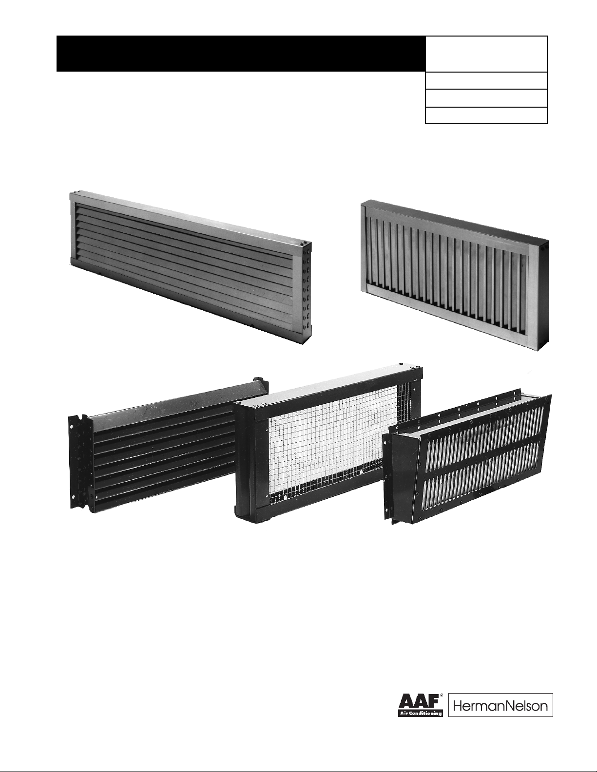
Louver & VentiMatic Shutter
Installation For AAF-HermanNelson® Classroom Unit Ventilators
(Models AVS, AVV, AVR, AHF , AHV, AHR, ARQ and ERQ)
Horizontal
Blade Louver
Ventimatic Shutter
Vertical
Blade Louver
Uncrating and Inspection
Upon receipt of the equipment, check carton for visible damage. Make a notation on the shipper's delivery ticket before
signing. If there is any evidence of rough handling, the
cartons should be opened at once to check for concealed
damage. If any is found, notify the carrier within 48 hours to
establish a claim and request their inspection and a report.
The Warranty Claim Department should be contacted.
Inspect the carton for any specific tagging numbers indi-
cated by the factory per a request from the installing contractor.
©1999 AAF-HermanNelson IM 473-1 (Rev. 6/99)
Check the number against the plans to be sure that the
unit will be installed in the correct location.
Note: Installation and maintenance must be performed by
qualified personnel who are familiar with local codes and
regulations, and are experienced with this type of equipment.
Caution: Sharp edges are a potential injury hazard. Avoid
contact with them.
®
Page 2
Installation Instructions
The louver supplied with these instructions is designed to let
in fresh air and to prevent water such as driving rain from
getting past the louver and into the unit. A weathertight seal
must be accomplished to keep unwanted air and moisture
from entering the occupied space. It is important to properly
install the louver per the instructions below.
1. If the fresh air opening has not yet been made, refer to
Figures 1 through 4 for the recommended locations.
Consult approved architectural plans for exact location.
2. Once the location has been selected, cut the opening in
the wall so that it is slightly larger than the louver being
installed.
3. If the opening has already been made, measure it to be
sure there is a minimum of
1
⁄2" (13mm) clearance around
all sides. Note that for masonry installations, a lintel
must be installed above all louvers. The louver is not
designed to replace the lintel.
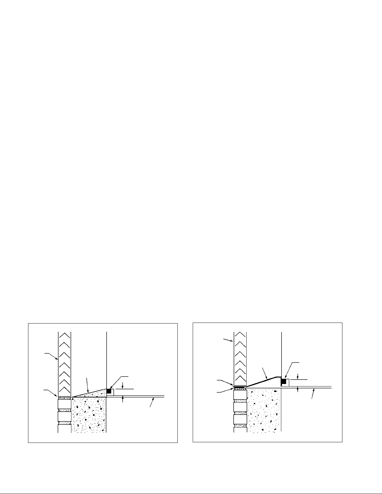
4. Before setting the louver, construct a sloping mortar
base to drain unwanted moisture to the outside. A
typical method is shown in Detail A. The mortar base
should be 1" (25mm) thick at the unit and taper toward
the louver. The 1" (25mm) thick mortar at the unit also
acts as backing against which the open cell gasket of the
unit can seal.
If it's not possible to make a mortar base as described above, then field supplied flashing must be
installed. A typical installation using flashing is shown in
Detail B. This flashing should terminate flush with the
exterior of the building. Place a bead of caulk under the
flashing to prevent moisture from wicking back to the
unit. Do not caulk the joint between the louver and
the flashing. This joint is designed to let unwanted
moisture escape.
5. Before setting the louver, make sure the drain lip (vertical) or drain holes (horizontal) are at the bottom and the
bird screen is towards the unit.
6. Place a heavy bead of caulk along the top and two sides
of the louver. Leave the bottom of the louver uncaulked
so that if moisture gets into the area between the louver
and the unit, it may drain outside unrestricted.
7. Place the louver in the opening so that it is recessed a
minimum
1
⁄16" (2mm) beyond the building facade or as
directed by the architect.
8. Mechanical fasteners may be desired or required to
further secure the louver in the wall. Employ a method
that is appropriate to the installation.
9. After the louver is solidly in place, run a bead of caulk
around the perimeter of the louver to seal it weathertight.
Caution: Do not plug the weep holes of the horizontal
louver nor the drip line of the vertical blade louver. This
will restrict the flow of unwanted moisture to the outside.
10. If flashing is used in place of a mortar base, caulk the
flashing where it meets the inside of the opening between the louver and the unit. This will prevent moisture
from getting under the flashing and into the occupied
space.
Detail A
Louver
No
Caulk
Page 2 / IM 473
Wall Unit
Cement Mortar;
Pitch Away
From Unit
1" (25mm)
Typical Installation Methods
Detail B
Louver
Unit Gasket
Floor
No
Caulk
Caulk
(By Others)
Wall Unit
Flashing
(By Others)
1" (25mm)
Unit Gasket
Floor
Page 3

Figure 1. 165⁄8" (422mm) Deep Unit with Open Pipe
Tunnel & Standard Louver Application
Figure 2. 16
Tunnel & High Louver Application with Chased
Wall
5
⁄8" (422mm) Deep Unit with Open Pipe
Piping
Lintel
(By
Others)
Louver
Floor Line
Cement
Mortar;
Pitch Away
From Unit
1"
(25mm)
Important: Gasket sealing
surface is required.
Figure 3. 217⁄8" (556mm) Deep Adapter Back Unit With
Standard Louver Application
Piping
Lintel
(By
Others)
Louver
Not Less
Than 3" (76mm)
Not More
Than 21" (533mm)
Cement Mortar;
Pitch Away
From Unit
Piping
1" (25mm)
Important: Gasket sealing
surface is required.
Floor Line
Figure 4. 217⁄8" (556mm) Deep Adapter Back Unit with
High Louver Application
Lintel
(By
Others)
Piping
Lintel
(By
Others)
Piping
Louver
Cement Mortar;
Pitch Away
From Unit
1" (25mm)
Important: Gasket sealing
surface is required.
Floor
Line
Louvers With Flanges
1. If the louver is supplied with flanges, follow steps 1
through 5 on page 2. Additionally, place a bead of caulk
on the inside of the top and side flanges that come in
contact with the building facade. Do not caulk the bottom
flange.
2. Place the louver in the opening and push it tight against
the building. Fasten it to the exterior of the building using
appropriate fasteners for the installation.
3. Seal the top and sides with a waterproof caulk to make it
weathertight. Do not caulk the bottom of the louver. To do
so may trap unwanted moisture behind the flange.
Louver
Cement
Mortar;
Pitch Away
From Unit
Not More
Than 28"
(711mm)
Piping
Floor
Line
Lining the Wall Opening
Thick wall applications require additional treatment of the
opening. The portion of the wall between the louver and the
unit will act as a plenum to bring outdoor air into the unit
ventilator. This plenum area should be lined using
of mortar or other suitable material. There are instances
where the specification requires a metal sleeve connection
between the louver and the unit. If a sleeve is used, properly
caulk it to insure a weathertight seal.
1
⁄2" (13mm)
IM 473 / Page 3
Page 4

VentiMatic Shutter Assembly
The VentiMatic shutter is a continuously variable, gravity
actuated, room exhaust vent which operates in direct response to positive static air pressure. It is a one-way shutter
that opposes any flow of air into the room. The Ventimatic
shutter allows a slight positive pressure in the room which
completely eliminates any unwanted friction.
When using the VentiMatic shutter exhaust system, it is
important that the VentiMatic shutter and the unit ventilator
wall louvers be mounted on the same wall. This will neutralize
the effect of the wind, forcing excess air into the room
through the unit ventilator louver because the same pressure
will work to keep the VentiMatic shutter closed and prevent
air from exhausting through it.
The VentiMatic shutter is generally mounted on a wall
exhaust louver. For larger units with 100% ventilation dampers, two VentiMatic shutters may be mounted side-by-side
on the same exhaust louver. The size and appearance of the
wall louvers used with the unit ventilator and VentiMatic
shutter, with or without decorative grilles, are identical.
Recommended
BC
24 27 2 4
(610) (659) (613) (267)
36 39 36
(914) (991) (918) (267)
48 51 48
(1219) (1295) (1222) (267)
60 63 60
(1524) (1600) (1527) (267)
72 75 72
Wall Openings
For Wall Louvers
Length Height 24" Shutter 36" Shutter cfm L/s
1
⁄8 101⁄2
1
⁄8 101⁄2
1
⁄8 101⁄2
1
⁄8 101⁄2
1
⁄8 191⁄2
(1829) (1905) (1832) (495)
As Directed
By Architect
Bird
Screen
Do Not
Block Drain
Holes With
Caulk or
Mortar
Notes:
1. Horizontal blade wall louver shown. Vertical blade wall louver also avail-
7"
(178mm)
Less
Than 9"
(229mm)
Cement Mortar
Maximum Number of VentiMatic
VentiMatic Shutters Shutter(s)
Which Can Be Mounted Air Capacity
On Standard Louver Maximum
1 0 500 236
0 1 750 354
2 0 1000 472
1 1 1250 590
0 2 1500 708
Cement Mortar
3⁄4" (19mm) Approx.
Steel Interior Wall
(Optional) See Note 3
Not
125⁄8"
(314mm)
3
⁄4" (19mm) Approx.
C
able with VentiMatic shutter.
2. Optional exterior grille matches unit ventilator wall louver in material and
design. Mounted on wall louvers.
3. Optional steel interior wall grille should be used to conceal the interior wall
opening whenever the VentiMatic shutter is not located behind shelf
cabinets or DraftStop enclosure. Hardware to mount the interior wall grille
is not included.
Aluminum Wall Louver
Assembly With Bird Screen
(See Note 1)
41⁄8"
(105mm)
237⁄8" (606mm)
357⁄8" (911mm)
Decorative Exterior Grille
Also Available (See Note 2)
103⁄8"
(264mm)
3" (76mm)
B
2" (51mm)
Single VentiMatic Shutter & Wall Louver
Aluminum Wall Louver
Assembly with Bird Screen
103⁄8"
(264mm)
(See Note 1)
B
Decorative Exterior Grille
Also Available (See Note 2)
Two VentiMatic Shutters & Wall Louver
or
3'' (76mm)
Center Cover
Steel
VentiMatic
Shutter
Assembly
VentiMatic
Shutter Ass'y
Installation
1. Install the louver per appropriate instructions found on pages 2 and 3.
2. Make sure all moving parts will operate unobstructed. Install interior grille if furnished.
AAF-HermanNelson
4900 Technology Park Boulevard, Auburn, NY 13021-9030 USA, (315) 253-2771
Printed on recycled paper containing at least 10% post-consumer material.
©1999 AAF-HermanNelson
Page 4 / IM 473-1 (Rev. 6/99)
 Loading...