

Page 1
ULLETIN
INSTALLATION AND
MAINTENANCE DATA
NO. IM 104
REVISED MAY 1967
-2
AMD-AMB
AIRCONS”
AIR COOLED CONDENSERS
I
.13600
INDUSTRIAL PARK BLVD., MINNEAPOLIS, MINNESOTA 55427 1 PHONE: 377-9750
AREA CODE: 612
I
Page 2
TABLE OF CONTENTS
GENERAL INFORMATION
ASSEMBLY OF UNITS
INSTALLATION OF UNITS
DIMENSIONAL DATA
PIPING
PIPING DIAGRAMS
..........................
...............
GENERAL
.........
............
.........
.............
4-5
6-7
INFORMATION
INSPECTION
When the equipment is received, items should be
carefully checked against the bill of lading to
sure all crates and cartons have been received.
All units should be carefully inspected for damage
when received. Visible or concealed damage should
be reported immediately to the carrier and a claim
filed for damage. All motor nameplates should be
checked to be sure they agree with the power supply
available.
be
RIGGING AND MOVING UNITS
The exact method of handling and setting the Aircon
depends on available equipment, size of unit, final
location, and other variables. It is therefore up to the
judgment of the riggers and movers to determine the
specific method of handling each unit. All units are
shipped on heavy skids and all vertical airflow units
have rigging holes in the legs. In addition, all the
larger units have rigging holes in each end of the
base channels for aiding in handling of the units.
See Figure 2 for suggested rigging.
Under no circumstances should the coil headers or
return bends
be
used in moving
these units.
LOCATION
A. General -The
marily for outdoor location. The fan motors are
enclosed within the cabinet for their protection
on AMB units. Motors are totally enclosed type
McQuay
Aircon is designed pri-
2
RECEIVER AND OPERATING
CHARGE.
ELECTRICAL WIRING.
3
3
START UP
OPERATION
MAINTENANCE.
8
REPLACEMENT PARTS
on
AMD
doors, the air leaving the unit should be discharg-
the
ed to
warmed air through the unit.
B.
AMD & AMB Horizontal Aircons.
type
flow
(inlet air side) facing the prevailing winds. Where
strong winds are common, it is recommended that
a wind deflector be used to discharge the air ver-
tically
capacity during varying wind conditions. The wind
deflector should be installed on the fan side of
the
unit. The wind deflector is shipped knocked
down,
units
are
tance
tween unit and wall. If it is absolutely necessary
to have the unit positioned so that the air discharge
the wall a distance of not less than
d
iameter
C.
AMD & AMB Vertical Aircons.
type units should be
fan diameter from a wall or other obstruction. If
two or
area, at least one fan diameter distance should be
maintained between adjacent units. Sufficient
free area should be left around and below unit to
avoid air restriction
required
not
......................
.......................
......................
.................
units. If the unit is to be installed in-
outdoors to prevent
units should be installed with the coil
from
the unit, so as to prevent loss of
complete
installed with coil facing a wall, a dis-
of
at least
is
of the fan.
more
with assembly instructions. If
24”
should be maintained be-
toward a wall. it should be
units are to be positioned in the same
for vertical
9-10
............
.12-19
...........
re-circulation
Horizontal air
Vertical air flow
located no closer
to
coil. Wind deflectors are
Aircons.
of the
spaced
1-1/2
times the
than one
from
11
12
19
20
--
Page 2
Page 3
ASSEMBLY OF UNITS
GENERAL
‘-
Aircons
except for the mounting legs, wind deflectors, and
head pressure control packages. Mounting legs and
wind deflectors are furnished with
nuts and washers.
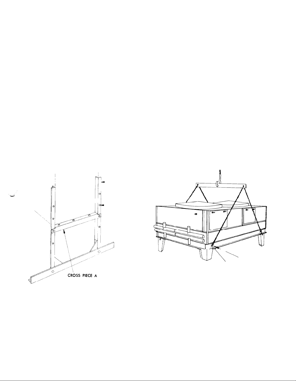
LEG ASSEMBLY (Horizontal
AMD
tional sets of holes for mounting. These holes are
furnished so that the legs can be positioned on the
unit at different leg heights. The location of cross
piece “A”,
of the unit above
On horizontal air flow units, the electric damper
motor, when furnished, is to bc installed on the under
are usually shipped completely assembled,
necessary
Aircons)
units are furnished with legs that have addi-
shown in Figure 1, determines the height
the
base.
bolts,
side of the damper section at the end nearest the
damper arm. See Figure 11, Page 16.
LEG ASSEMBLY
The legs of the vertical air flow units
adjustable. The legs are most easily assembled to
the unit when the unit is still in the upright position,
as
shipped.
work by 4 bolts furnished with the unit.
On vertical airflow units, when face dampers and
electric damper motors are used, it is necessary that
the leg
damper motor bracket be assembled to the corner
nearest the damper arm on the damper section. See
Figure 10, Page 16.
Each leg is fastened to the angle frame-
furnished
with the additional holes for the
(vertical Aircons)
are
not
FIGURE 1
HORIZONTAL
LEG ASSEMBLY
VERTICAL LEG
HOLES FOR
HEIGHT ADJUSTMENT
(AMD
ANGLE B
MODELS)
FIGURE 2 SUGGESTED RIGGING
U--\
AMB 50 THRU
8 THRU 30
AMD
20 THRU 45
AMB
140
INSTALLATION OF UNITS
The Aircon must be installed level to insure proper
drainage of liquid refrigerant and oil. Mounting holes
3/4"
diameter are provided on all models. See
ures 3
and 4. Sleepers are normally required when
distribution of load is necessary.
ished
with single section coils as standard on
two
(2)
smaller sizes, the
section coils of equal capacity are furnished as
AMD-8
Aircons
and
AMD-10.
Fig-
are furn-
the
Two
standard on all other sizes. All models are available
with coils circuited for use with multiple compressors. On
furnished with reference numbered tags for
cation relat
sions
See Tables 1 & 2.
multi-section Aircons, each section is
identifi-
ing
to the proper compressor. For dimen-
and
weights of horizontal and vertical
Aircons,
Page 3
Page 4
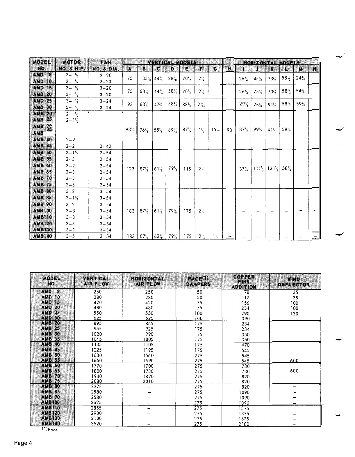
DIMENSIONAL DATA
TABLE 1
2- ::
r:g,
I:$&
ij.$%
2-l'/,
2-l
:
2-2
2-42
2-42
2-42
2-42
2-42
DIMENSIONAL AND PHYSICAL DATA
n
:,,L’
g?
-
75
18
-
18
18
15'.;
18
18
75
93
-
123
_
937;
58%
58?~
87',
79'ii
29?<
377,, 99:/,
111'4
-
121%
58'4
58'4
58'/;
58'/,
58s;
24:/,
54%
59%
72
a4
-
z
r,;
10
-
10
-
-
-
-
10
10
10
-
1’~
TABLE 2
-
18
-
NET WEIGHTS-LBS. (APPROX.)
(WITHOUT REFRIGERANT CHARGE)
130
160
160
160
160
160
160
600
600
600
600
600
600
-
_
-
-
-
Page 4
('IFace
damper on one fan section only.
Page 5
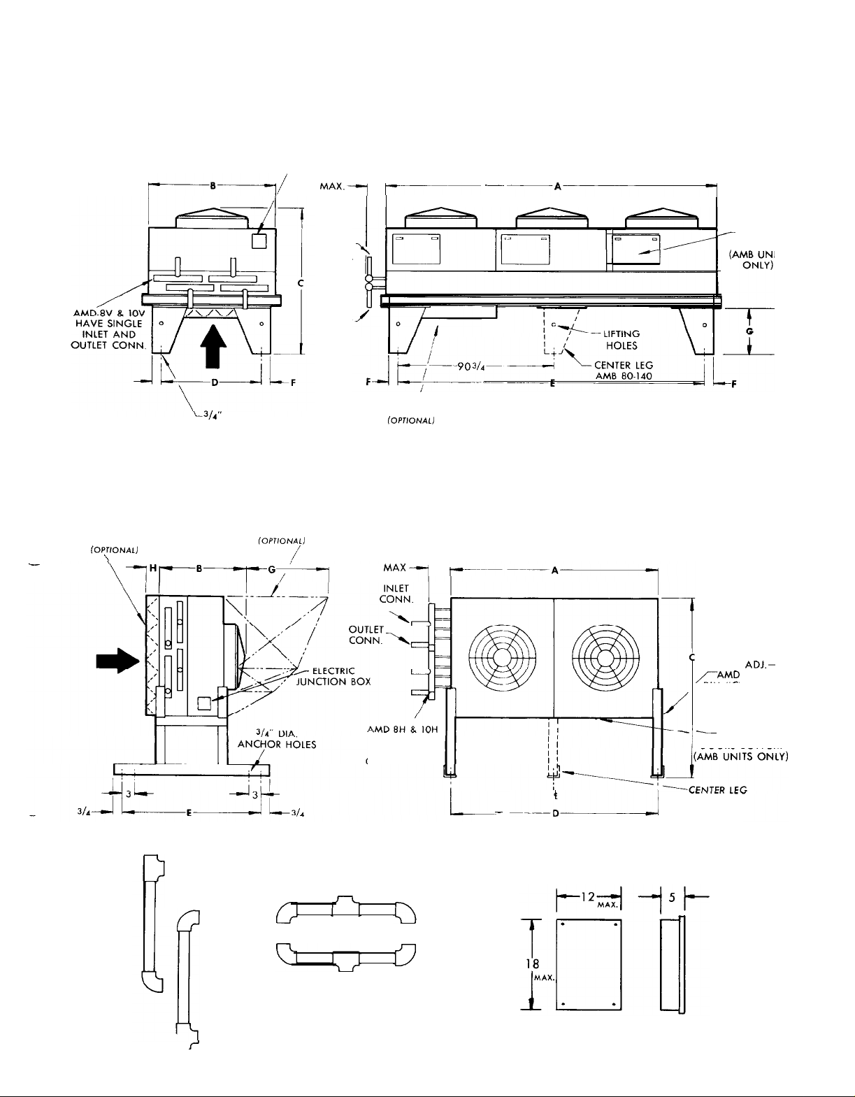
DIMENSIONAL DATA
FIGURE 3
,p-B---_l/
=/i’
DIA.
ANCHOR HOLES
FIGURE 4
INLET FACE
DAMPER
(OPTIONAL)
-
\
WIND DEFLECTOR
f0prf0~At)
VERTICAL AIR FLOW TYPE
ELECTRIC
JUNCTION BOX
4
MAX.7
INLET
CONN
OUTLET
CONN.
,--p
INLET
FACE DAMPERS
~~PTIoNAL)
ONE SECTION
ONLY
HORIZONTAL AIR
i
4
MAX _cl
--~ pAp
I
NOTE:
RIGHT HAND UNIT SHOWN
LEFT HAND UNIT AVAILABLE
FLOW TYPE
NOTE
RIGHT HAND UNIT SHOWN
LEFT HAND UNIT AVAILABLE
I
ACCES:
DOOR!
HOT
GAS
HORIZONTAL
r’
CONNECTION
MANIFOLDS
VERTICAL
UNITS
UNITS
HAVE SINGLE
INLET AND
OUTLET CONN
LEGS
,,/-AMD
DIM “C” MAY BE
INCREASED 6”
_
ACCESS
DOORS BOTTOM
_
_--_:,I
AMB 50.75
CONTROL PANELS
FANTROL AND DAMPERTROL
ADJ.-
UNITS
Page 5
Page 6

PIPING
GENERAL
The design of refrigerant piping for air cooled
densers involves a number of considerations not commonly associated with other types of condensing
equipment. The following text is intended for
a general guide to sound, economical and trouble-free
piping of air cooled condensers.
A.
Discharge
lines involves two objectives:
1. To minimize refrigerant pressure drop, since
high pressure losses
ser horsepower per ton of refrigeration.
2. To maintain sufficiently high gas velocity to
carry oil through to the
receiver at all loading conditions.
B.
Liquid
to allow free drainage of refrigerant from
denser coil to the receiver. If this is not done,
the liquid will build up in
denser coil,reduce the effective surface and
cause increased operating head
line should
may cause gas binding in the receiver. The liquid
line should be sized so the liquid velocity from
the condenser coil to the receiver
100 feet per minute. Beyond this velocity the
flow of liquid prevents air or other
si bles from passing back through the liquid line
into the condenser coil.
Line
C.
Sizing-Table No. 3 should be used as a
guide to proper sizing of discharge and liquid
lines. The discharge
on tons of refrigeration resulting in a line
sure drop per 100 feet. of equivalent, pipe length
corresponding to 2 degrees F change
temperature. The liquid
based on a maximum of 100
denser to receiver liquid velocity.
Lines
-The proper design of discharge
cause
Lines
-The liquid line must be
the
be
free of any
traps
line
capacities are based
line
capacities shown are
increased compres-
condenser
bottom of the
pressure.
or loops which
does
not exceed
non-conden-
in
feet
per minute con-
con-
use
as
coil and
designed
the
con-
con-
This
pres-
saturation
TYPICAL ARRANGEMENTS
In this case the design of the discharge line is
very critical
tion, the gas velocity might be too low at reduced
loads to carry oil up through the discharge line
condenser
and
size
would increase the gas velocity sufficiently
reduced
at
ing at
sized.
pressure drop. This condition can
one of’
1.
The d
the
and an
the
pressor.
2. A
shown
be sized to carry the oil at minimum load conconditions and line
that at the full load condition both lines would
have sufficient flow velocity to carry the oil to
the condenser.
B.
Figure 7, Page 8, illustrates another very common
application where the Aircon is located
tially
cciver. The principal problem encountered with
this arrangement is that there is frequently insufficient
liquid refrigerant from the condenser coil to the
receiver.
To guard against gas binding in the receiver
and liqu
are common to this arrangement, the receiver
should
let as possible. The liquid line should be free of
any
traps
runs,
ceiver.
If properly sized for full load condi-
coil. Reducing the discharge line
1 oad conditions; however, when operat-
full
load. the line would be greatly under-
and thereby
two
following
i schargc l
desired pressure drop at full load condition
oi 1 separator installed at the bottom of
trap
in the discharge 1 inc from the com-
double
in Figure 6, Page 8. Line “A” should
the
same
vertical
id
be
located as far below the condenser out-
or loops and if there are any horizontal
they
should be pitched down toward the re-
create an excessive refrigerant
be
overcome in
ways:
ine
may be properly
riser discharge line may he used as
"B"
should be sized so
level
as the compressor and
distance to allow free drainage of
buildup in the condenser coil, which
sized
on
essen-
for
re-
Page 6
Figure 5, Page 8 illustrates a typical piping ar-
A..
rangement involving a remote Aircon located at a
higher elevation, as commonly encountered when
the Aircon is on a roof and the compressor and
receiver are on grade level or in a
ment room.
basement
equip-
8,
C. Figure
application where two or more separate
are piped together to a single compressor.
1. It is very important that the two Aircons have
Page 8, illustrates a third very common
the
same capacity so that the refrigerant pres-
sure
drop
through each unit is equal.
Aircons
Page 7

PIPING
The piping should be arranged so that the
2.
lengths of run to and from each Aircon are
equal.
The above two points are particularly important
3.
in applications where the refrigerant receiver is
directly beneath the air cooled condensers. If
two unlike air cooled condensers or unequal
piping is used, the resultant
unequal
refrigerant
pressure drop may cause liquid to build up in
one of the condenser coils thereby reducing its
effective capacity.
D. Notice that in all illustrations
the
discharge line
is looped at the bottom and top of’ the vertical run.
This is done to
prevent
oil and
condensed
refrigerant from flowing back into the compressor and
causing damage. The highest point in the discharge
be
line should always
above the highest point in
the condenser coil; and it is recommended a
ging vent be provided at this point to
release
condensibles from the system.
It is also very important that the piping be arranged such that no excessive strain on the piping
or unit components can result. There seems to
general disregard for this factor. Typical examples
are the connecting of two condensers in
connected header to header without any offsets in
line,
the interconnecting
or running of a line direct-
ly from a coil connection through a wall or floor
the
and then scaling tightly between
line and the
opening. Provide sufficient flexibility to allow
pur-
non-
be a
parallel,
for
vibration, thermal expansion, and gradual base or
bui lding
The discharge line should include a loop to a level
E.
movement.
above the header of the condenser coil. When the
Aircon is located above the compressor, the discharge line should loop to the floor near the compressor before rising to the condenser coil. This
reduces the possibility of refrigerant condensing
the l ine
in
during the off cycle, and draining back
to the head of the compressor. Also, any oil travel-
the
ing up
head of’
Maintain gravity drainage in the liquid line from
F.
the condenser coil to the
binding is a condition usually caused by an
Gas
G.
undersized
receiver.
the
pipe wall will not drain back to the
the
compressor during off periods.
receiver.
liquid
line
between the condenser and
or because of traps in this same line.
Air or other non-condcnsibles also may cause
binding.
Multiple
H.
Aircons
may be connected in parallel
to product a condensing system of almost un-
l
imi ted capacity. When Aircons are connected in
parallel,
pressure drop to each Aircon.
included
the
piping should be equivalent for equal
A
drop leg should be
between each liquid manifold of sufficient
height to prevent back-up of liquid into the coil of
the unit with the lower pressure drop. The pressure
drop through each Aircon should be essentially the
same to distribute the load equally.
TABLE 3
REFRIGERANT LINE CAPACITIES (TONS)
19.2 IS.7
I-
27.2 21.8
47.3 39.0
73.2 61 .O
t
33.0255.0
(I) Line sizes based on pressure drop equivalent to 2 degrees per
IOC’
length.
Page 8

PIPING DIAGRAMS
FIGURE 5
CONDENSER
LIQUID LINE
FIGURE 6
-
DISCHARGE
TRAP
FJzEQ!%
FIGURE 7
LINE
COMPRESSOR
LIQUID LINE
!
c=LLI&
/DISCHARGE
LINE B
fl
DISCHARGE
LINE A
d
DISCHARGE LINE
CONDENSER
FIGURE 8
r
I
I
CONDENSER
J
-\
r
TRAP
b;
I
I
,/-‘\
? \
:
_-DISCHARGE LINE
r
I I
I
Page 8
LIQUID LINE
/
(_
RECEIVER )
-
74!==&
COMPRESSOR
Page 9

RECEIVER AND OPE
RATING CHARGE
A.
The refrigerant receiver should be installed in a
warm location to insure sufficient refrigerant pres-
sure for proper expansion valve operation immediately upon start of a system. This is particularly
important where systems are required to operate in
low ambient temperatures, otherwise special con-
trols for low ambient start may be required. The
receiver should not be installed in a space ordinarily warmer than where the compressor is located.
Otherwise, there is danger of migration of
ant to the compressor during extended off periods.
be
The sizing of the receiver should
determined by
totalling the refrigerant charge required for each
component in the system. i.e., Evaporator, piping,
condenser coil and receiver operating charge. The
total volume of the condenser and the receiver
should be at least 20% greater than this calculated
total charge. The refrigerant charge for each size
Aircon is shown in Table No.
If the system includes Seasontrol head pressure
B.
4
control, one additional consideration is necessary
in determining the system operating charge. Since
Seasontrol operates on the principle of maintaining
a fixed condensing capacity of the Aircon coil by
backing up liquid refrigerant in the coil, additional
refrigerant is required, and also a larger receiver
is required. When calculating the necessary re-
frigerant charge with Seasontrol application, multi-
ply the normal charge in Table No.
4
by appropri-
ate factor selected in Table No. 5, Page 10.
If the system with Seasontrol is to be charged
c.
when the condenser ambient is lower than 75 F,
McQuay
1.
recommends the following procedure.
Add a nominal charge to the system, that would
be estimated as a typical summer charge.
Block off enough of the condenser coil face to
2.
bring the head pressure up to 125 psi (assuming
use of R-12). By bringing the head pressure up
to 125 psi, the Seasontrol will open and prevent
being
any refrigerant from
held up in the condenser.
Check the liquid line sight glass. If the system
3.
is short, add refrigerant until sight glass clears.
Then add customary reserve charge. This then
would be normal summer charge.
4. The additional amount of refrigerant that must
be added to the system for winter or cold weather operation is determined by Tables 4
additional charge required is equal to the dif-
charge
ference between the winter
as determined from Table 5, Page 10 for the particular
design condition, and the summer charge indicated in Table 4.
refriger-
&
5. The
5. When the system is being charged and the ambient is high enough to normally bring the head
pressure up to 125 psi or higher, disregard
Paragraph “2”
When the condenser is operating at full capacity,
D.
at ambient temperature above 75 F, there should
be no liquid refrigerant flooded back in the condenser coil. The additional refrigerant introduced
into the system with the use of the Seasontrol
be
system must
stored in the receiver during sum-
mer operation. Therefore, the receiver must be
sized accordingly.
E.
Because of the rather large refrigerant charge
required in an air cooled condenser system, es-
pecially when using the Seasontrol system, it is
usually necessary to put additional oil into the
system. The amount of oil to be added varies
considerably
with the make of compressor used,
and whether the system is furnished with an oil
separator. The compressor oil level should be
watched carefully on initial start up of the system.
TABLE 4
REFRIGERANT CHARGE (LBS. R-l
(Summer operation above 60F without Seasontrol)
FACETtlSE
.88
R-500; .93-R-502:
21’))
@HARCE
ryxR
.21
.31
.21
.31
.33
.45
.25
.25
.38
.38
.50
.63
.54
.54
.68
.68
1.86
1.02
.77
1.02
1.02
1.02
1.29
1.29
1.52
2.04
,O
R-22;
Page 9
Page 10

RECEIVER AND OPERATING CHARGE
TABLE 5
SEASONTROL REFRIGERANT CHARGE FACTOR(‘)
(Multiply summer charge by factor for total charge)
I
2.6
3.5
4.2
4.7
5.1
5.5
5.7
2.5
3.3
3.8
4. I
4.5
.o
4.7
5.1
5.5
5.8
6.1
I.0
I
.o
I
3.0
4.1
4.7
5.2
5.6
5.9
6.2
6.4
I
.o
I
.6
/
1.7
2.8
4.2 ~
4.7
5.1
5.4
5.6
2.6
4. I
4.8
5.5
5.8
6.1
6.3
6.6
I
I.0
I .6
2.9
/
,
4.5
5.0 5.8 6.7
5.3 6.1
5.8
6.0
I
I
/
I
5.6
6.2
6.4
6.1
6.4
6.6
1.6
::‘,
5.5 6.5
I
6.7
6.9
7.1
I
7.2
7.4
4.4
5.3
6.0
6.9
7.0
7.2
y-
“j.
L
.i
(I)
Based on minimum condensing temperature of: 9OF for 30, 25, 20 Design T
SAMPLE PROBLEM
GIVEN:
AMB25
lbs. R-12. (Refer table
Aircon with normal summer charge of 12
4).
FIND:
(A)
Refrigerant charge with Seasontrol on system
designed on 30” TD, and 30 F minimum ambient.
(B)
Refrigerant charge of system above with com-
pressor
TABLE 6
having cylinder unloading to
WEIGHT OF REFRIGERANT IN COPPER
33-l/3%.
(LBS. PER 100 LINEAL FEET)
SOLUTION:
(A)
(B)
.D.:
3.5
4.2
4.7
5.4
5.4
80F
for
4.9
5.3
5.6
5.9
6.2
IO, 5 Design T.D.
15,
6.1
6.4
6.6
6.8
7.0
Seasontrol refrigerant charge factor from table
5
is 4.2. Therefore total charge = 4.2 x 12.0
=
50.3 lbs.
Cylindcxr
as reducing the design T.D. to 10 degrees
TD x
unloading to
331/3’:‘0
:{3-11’3% = 10” TD).
has same effect
Factor for
(30”
10OT.D.
and 30 F minimum ambient is 6.1. Therefore
total charge = 6.1 s 12.0 = 73.2 lbs.
LINES*)
Page
(2) Type L copper
10
tubing.
Page 11

ELECTRICAL WIRING
A.
The electrical installation should be in accordance with National Electrical Code, local
and regulations. Proper fuse protection should D.
be provided for the fan motors. Wiring Diagrams
shown are only basic and do not show fuses, disconnect switches, etc., which must be provided in
the field.
B.
c.
Aircons
The
fan is driven
have either two or three fans. Each
by
a separate motor.
All standard motors have internal inherent overload protectors. Therefore,
contactors
can be used
instead of starters requiring thermal protectors,
eliminating the problem of furnishing the proper
heating elements. Also. the cost of a contactor is
codes
somewhat less than that of a corresponding magnetic starter.
All
standard
AMD
(direct drive)
units have single
phase. 220 volt permanent split capacitor fan
motor
s.
These motors are factory wired into a
combination capacitor enclosure and junction box.
All standard
E.
driven
fan)
Aircons
AMB
(belt
furnished with three phase, 208/220-440 volt,
fan motors. The motors are wired into a common
junction box. See Figure 9. The motors must be
checked out for proper rotation. Unless the unit
order specifically calls for the lower voltage connection, the motors will be factory wired for the
higher voltage as a precautionary measure.
are
FIGURE 9
AMB UNIT
ELECTRICAL CONNECTIONS AND LOCATIONS
I
i
A.
FAN MOTOR CONNECTION TO OUTSIDE. JUNCTION BOX
LOCATED INSIDE.
AMB UNIT
6.
TYPICAL ACCESSORY KIT PANEL LOCATION. RUN MOTOR
CONNECTIONS DIRECTLY INTO CONTROL PANEL.
\
AMD UNIT
u/I
FAN MOTOR CAPACITOR AND JUNCTION BOX.
A.
AMD UNIT
uI
B. TYPICAL ACCESSORY KIT LOCATION.
Page
11
Page 12

START UP
Check for proper fan rotation. Air is drawn through
the coil on all Aircons. Be sure the fans turn freely.
Check belt alignment and tension. Front edge of fan
blade should extend approximately one third into fan
OPERATION
WINTER OPERATION
HEAD PRESSURE CONTROL
A.
The capacity of an air cooled condenser varies
with the difference between the entering air dry
bulb temperature and the condensing temperature
of the refrigerant. Since air temperature in some
regions varies as much as 100 degrees from summer to winter, some means must be employed to
keep the condensing temperature sufficiently high
to insure proper operation of the refrigerant ex-
pansion valve during low ambient operation.
B.
The low limit of the head pressure is dependent
upon the required pressure drop across the ther-
mostatic expansion valve, and for normal air con-
ditioning applications, should be maintained above
a condensing temperature corresponding to 70 F.
This, in effect, corresponds to a normal lower
limit of about 60 F ambient, air. Since air conditioning is not normally required at these lower
ambient air
control may not always be necessary. However, for
those applications which are of such a nature that
operation is required below 60 F ambient air
temperature,
denser head pressure control to meet specific job
requirements
“Fantrol”,
temperatures,
McQuay
and
“Dampertrol” and “Scasontrol.”
FANTROL METHOD
Fantrol
is an automatic winter control method and
will maintain a condensing pressure within reasonable
limits by cycling one fan on a two fan Aircon, or two
fans in sequence on a three fan Aircon in
outside air temperature entering the condensing coil.
FANTROL OPERATION
A. Fantrol control package consists of a weathertight
enclosure with motor starting contactor with 220V
holding coil, line voltage
minal strip suitably marked to correspond with
motor leads at the Aircon junction box. Thermo-
stat(s) and contactor are factory wired to terminal
condenser head pressure
offers three methods of con-
engineer/owner preference:
response
thermostat(s)
to
and ter-
shroud. Be sure all air or other non-condensibles are
purged from the refrigerant circuits through purge
valve located at the high point in the discharge line
piping.
strip as shown in Diagrams 1 and 2. Simple elec-
trical hookup of power from fused disconnect to
(220V)
contactor, control circuit
ing coil and motors to terminal strip is all the field
wiring that is required. The control package is to
be mounted at the Aircon with the therm o stat
bulb(s) located to sense the air temperature entering the condenser coil.
B.
This control is suitable for outside temperatures
above those shown in Table 8, Page 14. The
thermostat(s)
first fan when the condensing temperature is reduced to approximately 90 F. Table
lists the theoretical thermostat settings and minimum outdoor air temperature for several system
design TD’s. These settings arc theoretical since
they do not take into account variation in load.
should be field- set to shut off the
to contactor hold-
7,
Page 14,
FAN CYCLING-HEAD
PRESSURE CONTROL
A.
One
of
the
more obvious advantages of multiple
fan condensers over single fan units is the simple
inexpensive
and
reduction may be achieved. On a two fan unit,
stopping one fan reduces the condensing capacity
approximately
to
unit, stopping two fans, reduces the condensing
capacity
Fan motors are internal inherent overload
B.
cd, and
individual fan motors cycled by use of two pole,
heavy
and 2.
Thermostats are nominally set to maintain con-
C.
densing
a low of about
mostats
settings shown in Table 7, Page 14, will ordinar-
ily give
Where operation at ambicnts below the range shown
D.
on Table
Seasontrol
to
are
duty
temperatures
varies
satisfactory
way in which controlled capacity
55% of full rating. On a three fan
approximately 40% of full rating.
protect-
started by a single contactor, with the
thermostats. See Wiring Diagrams 1
between a high of 120 F arid
80
F. The final setting of the ther-
with system design conditions. The
operation.
9,
Page 14, are required, dampers or
may be added.
Page 12
Page 13

OPERATION
b
DIAGRAM 1
230-60-
1
I
;
CONTACTOR
I
I
I
FANTROL AMD MODELS
.--_-
220v INTERLOCK TO START
--__
WITH COMPRESSOR
DIAGRAM 2
208-2201440-60-3
I
I
I
CONTACTOR
I
i
! I I
I
I
Ml
0
FANTROL AMB MODELS
FAN MOTORS
t--
THERMOSTAT
I
ON 3 FAN
UNITS ONLY
Page 13
Page 14

OPERATION
TABLE 7 FANTROL THERMOSTAT SETTINGS
(I) Settings are for normal air conditioning application. For other applications thermostats can be adjusted to maintain ade-
quate condensing pressure within limits of table.
(F)(l)
TABLE 8 FANTROL HEAD PRESSURE CONTROL DATA
45
63
72
35
54
15
27
40
52
65
49
56
63
69
76
53
57
62
66
71
42
49
55 67
61
67 74
66
68
71
73
75
61
64
70
3-a
‘Q
r
Page 14
TABLE 9 DAMPERTROL HEAD PRESSURE CONTROL
-30
-30
-10
15
40
-30
-30
-22
5
34
(2) Minimum outside air temperature based on
or two fans on three fan units.
(3) Minimum outside air temperature is based on
city and 80F condensing temperature at 50% and 25% compressor capacity.
Dampertrol
maintaing
used in
90F condensing temperature at 100% and 75% compressor capa-
conjunctior
with
Fantrol
cycling one fan on two fan units
DATAt2)
-30 24
-I4
I5
24 52
42
63
30
38
46
55
32
42
61
fre
ti
Page 15

OPERATION
DAMPERTROL METHOD
The dampertrol method utilizes the principle of
modulating the air flow through the condenser coil
and is used in conjunction with fan cycling control
to maintain the required head pressure.
DAM PERTROL “A”
A.
The electric motor type control is the conventional
method of’ controlling dampers on
use
of’ this
system
permits adjustment of both
head pressure range and differential.
B.
This
damper
control is to be used with fan cycling
Aircons.
The
control where a lower minimum range of ambient
operation
VARIATIONS OF DAMPERTROL
A.
Dampcrtrol is avail able in two arrangements:
1. Dampertrol A, which employs an electric
damper motor.
2.
Dampcrtrol B, which is direct refrigerant
sure operated.
B.
Dampertrol A utilizes a modulating pressure control,
damper motor, etc.,
and is intended for appli-
cations where head pressure is to be maintained
to close tolerance and where field adjustment is
desirable.
c.
Dampertrol
tuated damper operator and
B
employs a refrigerant pressure ac-
eliminates
the
electric wiring, pressure switches, etc. It is
tory installed and greatly
ordinarily required for
reduces the
damper
control
field labor
tions. Dampertrol B has a fixed operating range
and will modulate head pressure over a range of
170-250
psi for R-22 and
100-160
for R-12.
pres-
need
for
fac-
installa-
required and where range and differential adjustment is desired.
C.
Wiring
with damper operation. The thermostat or thermo-
stats are adjusted to cycle according to the
trol instructions. The damper control is then set to
modu l ate
sired
minimum operating range of this system under
various conditions.
D.
The adjustment, of both the range and differential
is
not at
motor and the damper arm should be adjusted so
that at the low pressure end of the motor arm
travel
an
11, Page
ting
produce
precaut ionary
than obtainable with fan cycling only is
Diagram 3
the dampers and thereby maintain the de-
head
pressure. Table 9 shows the effective
made
at the modulating pressure control and
the motor
the
face
inch from closed
16,
the face
shows a system for fan cycling
The linkage between the damper
damper remains open about
position. See Figures 10 and
for typical damper linkage. Permit-
dampers to close completely may
excessive overload of the fan motor. As a
measure. it is advisable to set the
Fan-
3/8
of
damper blades at the minimum opening that will not
DAMPERTROL COMPONENTS
Damper Section -The damper section consists of
inlet dampers of opposed balanced blade type. located
to cover one fan section of the Aircon.
excessively
ammeter).
will
on
under l ow ambient conditions the motors will
stand considerable overloading.
overload the motor, (by use of an
It is to be noted also that the damper
ly be
closed
at quite low ambient, and
DIAG
RAM 3 DAM PERTROL “A”
DAMPERTROL PANEL FANTROL PANEL
115/230-60-1
t
MOD. PRESS I ; HIGH PRESS.
TRANS.
TO COMPRESSOR
lNTERLOCK
DAMPERTROL A PANEL FOR AMB TWO FAN UNIT SHOWN.
THREE FAN UNITS AND AMD (SINGLE PHASE) UNITS
SIMILAR.
1
I
I
,’
22_o_v-
/-
CONTACTOR
THERMOSTAT
Page 15
Page 16

OPERATION
FIGURE 10
THE DAMPER MOTOR IS SHIPPED IN
“CLOSED” POSITION (AS SHOWN).
AFTER THE MOTOR IS WIRED IT WILL
ASSUME “CLOSED” POSITION IF TER-
MINALS “R
IT WILL ASSUME “OPEN” POSITION .
IF “R TO 8” IS SHORTED.
“A” SHOULD BE 45“ WHEN DAMPERS
ARE IN FULLY CLOSED POSITION.
“B”
MOTOR IS TO THE END OF ITS CCW
TRAVEL.
TO W” ARE SHORTED.
SHOULD BE
5i’!h”
WHEN DAMPER
DAMPER MOTOR ASSEMBLY-VERTICAL
*
;“i-;_,
BALL JOINT SHOULD’ BE
LOCATED NEAR MIDDLE
POSITION OF SLOT.
ss-.
& ‘2,. _
.>.rp.,-
.
. .
.. ‘+z.._
!
~
1
I
,__
_- ,e
MOTOR HOOD
FIGURE
THE DAMPER MOTOR IS SHIPPED IN
“CLOSED” POSITION (AS SHOWN).
AFTER THE MOTOR IS WIRED IT WILL
ASSUME “CLOSED” POSITION IF TERMINALS “R TO W” ARE SHORTED.
IT WILL ASSUME “OPEN” POSITION
IF “R TO B” IS SHORTED.
“A” SHOULD BE
ARE IN FULLY CLOSED POSITION.
“B”
SHOULD BE
MOTOR IS TO THE END OF ITS CCW
TRAVEL.
11
45’
WHEN DAMPERS
10’
WHEN DAMPER
DAMPER MOTOR
ASSEMBLY-HORIZONTAL
BALL JOINT SHOULD BE
LOCATED NEAR MIDDLE
POSITION OF SLOT.
Page 16
DAMPER MOTOR
Page 17

OPERATION
DAMPERTROL “B”
A.
Dampertrol “B” consists of a refrigerant pressure
actuated damper operator, factory mounted to the
damper frame, as illustrated in Figure 12. Interconnecting tubing is connected from receiver or
condenser outlet to damper operator.
B.
The pressure operator positions the dampers in
response to pressure of the refrigerant leaving the
condenser. One side of the piston is loaded by a
bellows operated by
posite side of the piston is spring opposed. When
refrigerant pressure is reduced to 250 psi for K-22
or 160 psi for R-12, dampers begin to close and
continue to modulate until completely closed when
refrigerant pressure is reduced to
or
100
psi for R-12.
The control is suitable for ambient temperatures
as shown in Table 9, Page 14.
c.
The pressure operator is factory installed on the
Aircon. However, the
connection from the operator to the system is not
made. The pressure connect ion may be made to the
top of the receiver, to the liquid line between the
refrigerant
l/4”
pressure. The op-
170
psi for R-22
O.D. pressure line
condenser and receiver, or to the liquid header.
However, if used in conjunction with
the connection must be made between the liquid
line Scasontrol valve and the condenser. The connection should not be made to the hot gas line or
the
hot gas header because of effect of possible
objectionable pulsations sometimes present on the
entering side of the condenser.
A shut off valve in the line between the operator
D.
system
and
is recommended.
Seasontrol,
DAMPERTROL-PRESSURE OPERATOR
Upon starting of the system check the position of
the damper blades. The damper blades should be open
3 /8"
about
stroke. The differential range of this operator is quite
wide so that the dampers will not be completely open
until the system reaches a fairly high head pressure.
The
out away from the cylinder with increase in pressure.
at the closed end of the damper operator
direct
ion of the stroke is such that the stroke is
FIGURE 12 DAMPERTROL “B”
HEADER END
L
PRESSURE LINE CONNECTION
TO LIQUID OUTLET OR RECEIVER
Page 17
Page 18

OPERATION
SEASONTROL METHOD
A.
The Seasontrol III system of head pressure control
is based on liquid refrigerant flooding back into
the condenser and thereby cutting down its effective condensing capacity.
B.
The Seasontrol III system is an improved head
pressure control incorporating two modulating
valves. A check valve is recommended as shown in
14
Figures 13 and
to the condenser during the off cycle. This valve
is a field supplied item. This system operation is
independent of difference of elevation
condenser and receiver. It, therefore, permits
receiver and condenser to be more conveniently
located
The main or liquid line valve is normally closed,
C.
and opens on pressure rise in the condenser. This
valve is located in the liquid line between the
condenser and receiver.
open and closes on pressure rise. This valve is
the compressor and the liquid line between the
D.
to suit specific job conditions.
The secondary gas or by-pass valve is normally
located in the line between the discharge line from
liquid Seasontrol valve and the receiver (See
Figures 13
The system operates as follows:
1. On system start up, the by-pass valve is normally open and the main or liquid valve is
closed. Hot gas moves from the compressor,
part going into the condenser, and part going
through the bypass circuit through the
to prevent refrigerant migration
between
& 14).
the
the
open
valve and into the receiver. The by-pass gas
goes directly into the receiver to maintain or
build up pressure in the receiver as liquid
leaves. As the compressor continues to run. hot
gas condenses in the condenser and raises the
on
liquid level since the main valve
side of the condenser is still closed. As the
liquid level rises: the condensing capacity of
the
condenser decreases and as a result the
head
pressure rises. The by-pass gas maintains
or
raises
the pressure in the receiver. As the
pressure
point of the valve, the liquid valve starts modulating towards the
liquid to leave the condenser and flow into the
receiver.
starts modulating towards the closed position
limiting the hot gas flow into the receiver. The
modul ating
per l
proper head pressure.
tem is ordinarily used to extend the range of a
fan
conjunction with the Seasontrol reduces the
amount of the refrigerant charge required for a
spcci fic
Refer to Refrigerant Charge Table 4, Page
and Refrigerant Charge Factor Table 5, Page
10.
in the condenser rises to the control
open
position, permitting
At the
iquid
On multi-fan condensers. the Seasontrol sys-
cycling
minimum design temperature condition.
same
time
the
of the two valves maintain the
lcvcl
in the condenser to maintain
system. The use of fan cycling in
the leaving
by-pass valve
pro-
9,
Page 18
FIGURE 13
DISCHARGE LINE
--
1
LIQUID LINE
0
CHECK
RECEIVER
MODELS AA
GAS VALVE
4, ,
“AfVE
CHECK VALVES NOT FURNISHED, TO BE FIELD INSTALLED
I
&
BA
AIRCON
LIQUID VALVE
FIGURE 14
MODELS CA
&
LARGER
Page 19

OPERATION
TABLE 10
25
50
75
125
.- 200
( I ) Net refrigeration effect at evaporator.
TABLE 11
SEASONTROL
SEASONTROL
IO
Ill
CONNECTIONS
III
VALVE SELECTION
AA-22
BA-22
CA-22
DA-22
E
B-22
F
B-22
,
I
I
TABLE 12
Valves are supplied set as Indicated for R-12 or R-22
R-502.
For R-500 valves must be adjusted in the field. Order
R-12 model and
IO AA-12
20
40
60
I
00
175
BA-12
CA-12
DA-12
EB-12
F
B-12
VALVE SETTINGS (PSIG)
adJust
at
time
of Installation.
MAINTENANCE
GENERAL
A.
Type AMD and
maintenance.
the fan shaft bearings, motor bearings, and occas-
ionally clean the surface of the coil. During the
initial break-in period, it is advisable to check the
belt tension after the first
Usually, by this time. the belts have acquired their
permanent stretch and further adjustments should
not be necessary. It is advisable, however, to recheck the belt tension at. 3 month intervals, and if
necessary, make any adjustments.
B.
The fan shaft mandrel does not require lubrication
at the time the unit is put into service. The fan
bearings
shaft
STANDARD OIL COMPANY,
Lithium Grease.
The Aircon coil will require a periodic cleaning
c.
and this can
cleaner or a pressurized air stream.
AMB Aircons
require a minimum of
All that is required is to lubricate
48
hours of operation.
should be greased once a year using
AMCO
Multi-Purpose
DO NOT
BE
accomplished by a brush, vacuum
OVERLUBRUCATE
MOTOR
A.
All
I motors are ball bearing, pre-lubricated and do
not require the addition of grease at the time of
installation. Periodically. the ball bearings should
be cleaned and the grease renewed to gain the
ultimate in service from the motor bearings.
B.
Extreme
matter from entering the ball bearings. It is also
important to avoid overgreasing. Only a high
grade,
characteristics
littlc
the
prefcrrably
aration of oil and soap under operating and storage
conditions. and freedom from abrasive matter, acid
alkali and moisture.
Specific gwasing
C.
the tag attached to the motor and should be gener-
ally
care must be exercised to prevent foreign.
clean
mineral grease having the following
should be used: Consistency: a
stiffer than that of
operat
ing temperature range; melting point
over
150 C (302
vaselinc,
maintained over
F); freedom from sep-
instructions are to be found on
greasing
Page 19
Page 20

REPLACEMENT PARTS
When writing to
McQuay
for service or replacement
parts, refer to the model number and serial number of
the unit as stamped on the Serial Plate, attached to
the unit. If replacement parts are required, mention
date
the
of installation of the unit and the date of
failure, along with an explanation of the malfunctions
and a description of the replacement parts required.
Refer to Replacement Parts List No. RPL 400.
“Bulletin illustrations cover the general appearance of
the right to make changes in design and construction at any time without notice.”
McQuay
products at time of publication and we reserve
@
 Loading...