

McQuay ALZ “B” Maintenance Manual
Air cooled water chillers
Air cooled motocondensing unit
ALZ “B” 011.1 ÷ 038.2
ALP “B” 011.1 ÷ 038.2
Cooling capacity from 40 to 145 kW
50Hz – Refrigerant: HFC 407C
Scroll Compressors
Installation and maintenance manual
304 C – 02/06 D
Date: June 2002
Supersedes: 304 C- 02/01 C

304 C – 02/06 D – pag. 2/16
Introduction
Purpose of the manual
The manual allows the installer and the operator to perform correctly all the operations referred to the installation
and maintenance of the chiller without provoking any damages to the unit or to the qualified personnel.
Therefore the manual is a great help for the qualified personnel that have to arrange the equipment to provide the
correct installation in accordance with local codes and regulation.
Inspection
When the equipment is received, all items on the bill of lading should be carefully checked to insure a complete
shipment. All units should be carefully checked and all shipping damage should be reported to the carrier. The unit
serial plate should be checked before unloading the unit to be sure that it agrees with the power supply available.
Physical damage to unit after acceptance is not McQuay responsability.
Responsabilities
McQuay Italia declines all present and future responsabilities referred to injuries to people and damage to things
and unit, coming from operators negligence, the unrespected installation/maintenance data carrier in this manual,
the lacking of the current regulations respect referred to the safety of the equipment and the qualified personnel.
Servicing and maintenance
Servicing and maintenance of these unit must carried out by experienced personnel with specifing training in
refrigeration. Repeated check the safety devices and continous cycling of control components must be analyzed
and corrected before being reset.
The simple design of the refrigeration circuit totally eliminates potential problems during normall unit operation. No
maintenance work is needed on the refrigeration circuit as long as the unit is operating normally.
Characteristics
General description
McQuay International introduces their newest air cooled water chiller ALZ/ALP equipped with scroll compressors
and electronic control system. McQuay have once again succeded in developing a high quality product with
extraordinary performance which is able to satisfy HVAC applications.
McQuay units are completely factory assembled, piped, wired and charged with refrigerant and shipped ready for
the installation.
Each unit consists of scroll compressors, condenser coils with independent subcooler circuits, multiple propeller
type direct drive condenser fans with independent fan motors, heavy-gauge weatherproof casing and weatherproof
electrical control centre containing all necessary and operating controls and motor starting equipment.
ALZ/ALP units are high thermodynamic engineering products, studied with high accuracy in balancing
compressors, condensers and evaporators in order to offer high performances and wide safety margins. The
choose of the materials and the equipments adopted for the products has been made without any compromises,
taking care of quality and long life purposes. The products meet ISO 9001 requirements, an assurance, beyond
any doubts, of the high producing standards followed by McQuay.
304 C – 02/06 D – pag. 3/16
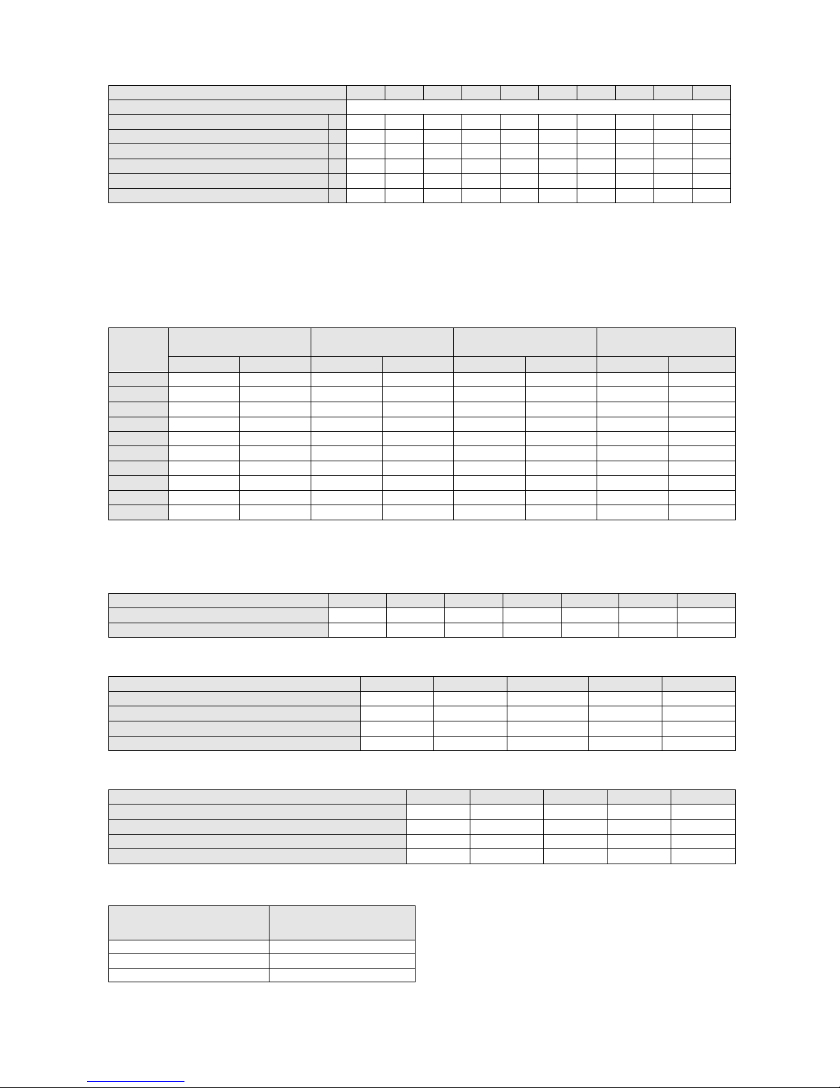
Electrical data ALZ/ALP “B”
Unit size 011.1 013.1 017.1 020.1 022.2 025.2 029.2 033.2 036.2 038.2
Standard voltage (1)
400 V - 3f – 50 Hz + NEUTRAL
Nominal unit current (2)
A
32,3 37,8 45,4 54,8 64,1 75,9 83,9 93,5 99,4 109,8
Max compressor current (3)
A
29,3 35,4 44,4 54,6 61,0 74,4 83,8 95,2 98,0 109,6
Fans current
A
5,4 5,4 5,4 5,4 8,1 8,1 8,1 8,1 10,8 10,8
Max unit current (3)
A
34,7 40,8 49,8 60,0 69,1 82,5 91,9 103,3 108,8 120,4
Max unit inrush current (4)
A
151,6 154,3 203,1 207,8 186,2 195,0 246,0 253,2 260,4 268,2
Max unit current for wires sizing (5)
A
45,4 63,4 65,4 75,4 88,1 124,1 126,1 128,1 140,8 150,8
Notes: (1) Allowed voltage tolerance ± 10%. Voltage unbalance between phases must be within ± 3%.
(2) Nominal current are based on: 12/7 °C entering/leaving evaporator water temperature and 35°C ambient temp.
(3) Maximum current are based on: 14/9 °C entering/leaving evaporator water temperature and 40°C ambient temp.
(4) Inrush current of biggest compressor + nominal absorbed current of the other compressors.
(5) Compressor FLA + fans current.
Operating limits
Entering evaporator
water temperature
Leaving evap. water
temp.(without glycol)
Evaporator water ∆∆t
Ambient temperature
ALZ
Min. (°C) Max (°C) Min. (°C) Max (°C) Min. (°C) Max (°C) Min.(°C)(*) Max (°C)
011.1
8 20 4 15 4 8 15 42
013.1
8 20 4 15 4 8 15 42
017.1
8 20 4 15 4 8 14 42
020.1
8 20 4 15 4 8 12 40
022.2
8 20 4 15 4 8 15 42
025.2
8 20 4 15 4 8 13 40
029.2
8 15 4 10 4 8 12 40
033.2
8 15 4 10 4 8 10 40
036.2
8 20 4 15 4 8 15 42
038.2
8 20 4 15 4 8 15 40
(*) for ambient temperature down to –18°C low ambient kit is required (fan speed control)
Altitude correction factor
Elevation above sea level (m)
0 300 600 900 1200 1500 1800
Barometric pressure (mbar)
1013 977 942 908 875 843 812
Cooling capacity correction factor
1,000 0,991 0,981 0,972 0,962 0,953 0,943
Ethylene glycol and low ambient temperature correction factors
Air ambient temperature °C
-3 -8 -15 -23 -35
% of ethylene glycol correction factor
10 20 30 40 50
Cooling capacity correction factor
0,986 0,980 0,973 0,966 0,960
Flow rate correction factor
1,023 1,054 1,092 1,140 1,200
Water pressure drops correction factor
1,061 1,114 1,190 1,244 1,310
Low temperature operation performance factors
Ethylene glycol/water leaving temperature °C
2 0 -2 -6 -8
Cooling capacity correction factor
0,842 0,783 0,725 0,615 0,562
Power input compressors correction factor
0,950 0,934 0,918 0,870 0,845
Min % of ethylene glycol
10 20 20 30 30
Max air ambient temperature °C
40 40 38 34 32
Fouling factor
Fouling factor
m2 °C / kW
Cooling capacity
correction factor
0,044 1,000
0,132 0,986
0,308 0,939
304 C – 02/06 D – pag. 4/16
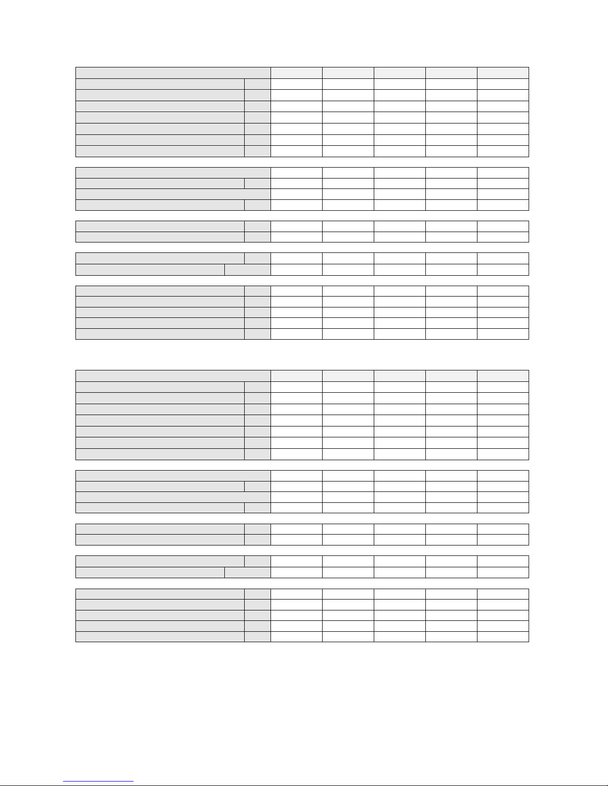
Physical data ALZ “B” HFC 407C units
Unit size 011.1 013.1 017.1 020.1
022.2
Cooling capacity (1) kW
42,7 49,4 60,6 71,8 84,3
Power input (1) kW
13,9 16,9 22,0 27,4 29,4
Cooling cap. heat recovery cond.(2) kW
43,5 52,7 62,5 79,7 87,5
Heating capacity (2) kW
56,2 67,0 82,2 103,7 113,5
Power input heat recovery cond. (2) kW
14,5 16,3 22,2 27,2 29,6
Desuperheaters heating capacity (3) kW
10,4 12,2 14,8 17,7 21,0
Desuperheaters pressure drops (3) kPa
14 18 15 20 18
Scroll compressors
No. of compressors / No of circuits
1 Tandem/1 1 Tandem/1 1 Tandem/1 1 Tandem/1 2 Tandem/2
Oil charge l
6,5 6,5 10,4 13,2 6,5+6,5
No. of reduction steps
2 2 2 2 2
Refrigerant charge kg
5,5 6,0 7,0 8,5 11,0
Plate heat exchange
Water volume l
2,6 2,9 3,6 4,4 5,2
Max. water pressure bar
30 30 30 30 30
Condenser fans
No. of fans / Diameter mm
2 / 630 2 / 630 2 / 630 2 / 630 3 / 630
Motor power / rotation regime kW / rpm
0,6 / 880 0,6 / 880 0,6 / 880 0,6 / 880 0,6 / 880
Dimensions and weights
Unit length mm
2780 2780 2780 2780 3530
Unit width mm
1200 1200 1200 1200 1200
Unit height mm
1400 1400 1400 1400 1400
Standard unit shipping weight kg
453 576 609 662 733
Unit with two pumps and tank weight kg
503 666 699 762 833
Unit size 025.2 029.2 033.2 036.2
038.2
Cooling capacity (1) kW
95,3 107,5 117,2 133,5 144,5
Power input (1) kW
36,2 41,3 47,7 49,6 54,8
Cooling cap. heat recovery cond.(2) kW
100,4 116,1 123,9 143,9 151,3
Heating capacity (2) kW
132,4 152,4 166,3 189,6 200,9
Power input heat recovery cond. (2) kW
35,8 41,5 47,9 51,2 55,4
Desuperheaters heating capacity (3) kW
23,4 26,6 28,4
32,7 35,7
Desuperheaters pressure drops (3) kPa
20 19 24 24 25
Scroll compressors
No. of compressors / No of circuits
2 Tandem/2 2 Tandem/2 2 Tandem/2 2 Tandem/2 2 Tandem/2
Oil charge l
6,5+6,5 6,5+10,4 10,4+10,4 10,4+13,2 13,2+13,2
No. of reduction steps
2 2 2
2 2
Refrigerant charge kg
13,0 16,0 18,0 23,0
23,0
Plate heat exchange
Water volume l
5,8 6,8 7,6 9,7 9,7
Max. water pressure bar
30 30 30 30
30
Condenser fans
No. of fans / Diameter mm
3 / 630 3 / 630 3 / 630 4 / 630 4 / 630
Motor power / rotation regime kW / rpm
0,6 / 880 0,6 / 880 0,6 / 880 0,6 / 880 0,6 / 880
Dimensions and weights
Unit length mm
3530 3530 3530 4280 4280
Unit width mm
1200 1200 1200 1200 1200
Unit height mm
1400 1400 1400 1400 1400
Standard unit shipping weight kg
860 892 940 1115 1140
Unit with two pumps and tank weight kg
960 992 1040 1215 1240
Notes: (1) Nominal cooling capacity and power input are based on: 12/7 °C entering/leaving evaporator water temperature;
35°C ambient temperature.
(2) Nominal cooling capacity, power input and heating capacity are based on: 12/7 °C entering/leaving evaporator
water temperature; 45°C leaving HR water temperature.
(3) Desuperheaters heating capacity and pressure drops are based on: 12/7°C entering/leaving evaporator water
temperature; 40/45°C entering/leaving desuperheater water temperature; 35°C ambient temperature.

304 C – 02/06 D – pag. 5/16
Safety measures
The unit must be suitably clamped to ground.
It is necessary to follow these cautions and warnings:
- The unit must be lifted only by using the proper tools able to support the weight of the unit.
- No admittance to unauthorized or unqualified personnel.
- No operation on electrical components is allowed without having switched off electricity supply.
- No operation on electrical components is allowed without using insulated platforms; no water or moisture should
be present.
- All the operation on refrigerant circuit and pressurised components are to be performed by qualified personnel
only.
- Compressor substitution or oil addition in this one must be performed by qualified personnel only.
- Sharp edges and coil surface are a potential injury hazard. Avoid contact with them.
- Disconnect all power to the unit while servicing condenser fan motors. Failure to do so may cause body injury.
- Avoid unrelated bodies into the water piping during the unit connection to the water system.
- It is necessary a mechanical filter for the piping connected to the exchangers entry.
Installation
Before any operation please check the instruction for use.
Warning
Installation and maintenance are to be performed only by qualified personnel who are familiar with local codes and
regulations, and who are experienced with this type of equipment. Must be avoided the unit installation in places
that could be considered dangerous for all the maintenance operations.
Transport
It is necessary to be sure of the stability of the unit during transportation. Therefore the unit is supplied with a
transversal wooden beam placed on the unit base that must to be removed only after the final destination. In case
the unit has to be moved again, a similar solution is necessary.
Handling and lifting
Care should be taken to avoid rough handling or shock due to the unit drop. Do not push or pull the unit from
anything else than the base. When it is necessary to lift the unit suitable buttonholes are provided in unit base to
arrange spreader bars and cables to prevent damage to the condenser coils or cabinet.
Location
The ALZ units are produced for outside installation on roofs, floors or below ground level on condition that the area
is free from obstacles for the passage of the condensation air. The unit should be positioned on solid foundations
and perfectly level; in the case of installation on roofs or floors, it may be advisable to arrange the use of suitable
weight distribution beams. When the units are installed on the ground, a concrete base at least 250 mm wider and
longer than the unit’s footprint should be laid. Furthermore, this base should be sufficiently robust to withstand the
unit weight mentioned in the technical data table. When the units are positioned in areas which are easily
accessible by persons or animals, it is advisable to fit guards (option) to protect the condenser coil and the
compressors.
Besides to obtain the best performance the location area it is necessary to follow the next precaution and advise:
• Avoid air flow recirculation.
• Take care that obstacle do not obstruct air flow.
• Breezy ambient is required to ensure the right air suction and delivery.
• To reduce noise and vibration a stiff floor is required.
• To avoid that condenser coils get dirty avoid dusty ambient.
• Chiller water must be quite clean and deprived of oil trace and rust particles. It is necessary a water filter on the
entering water pipes.
 Loading...