

Page 1

Installation, Operation and Maintenance Manual
Air-Cooled Screw Compressor Chiller
ALS 141C through 420C
60 Hertz
IOMM ALS-3
Group: Chiller
Part Number: 330145707
Date: March 2001
Supersedes: IOMM ALS-2
Page 2

Table Of Contents
Introduction.............................3
General Description........................................3
Nomenclature...................................................3
Inspection........................................................3
Installation and Start-up ............3
Handling...........................................................4
Location............................................................5
Service Access................................................5
Clearance Requirements.................................6
Vibration Isolators...........................................9
Lifting and Mounting Weights...................10
Water Piping..................................................12
System Water Volume...................................13
Variable Water Flow......................................13
Evaporator Freeze Protection......................14
Flow Switch....................................................14
Water Connections.......................................15
Refrigerant Charge........................................15
Glycol Solutions............................................15
Remote Evaporator................16
General............................................................16
Performance Derate Factors ........................16
Refrigerant Piping.........................................17
Startup Procedures .......................................22
Dimensions, Remote Evaporator................23
Water Flow and Pressure Drop26
Physical Data ......................... 28
Compressor Staging ..............32
Unit Layout and Principles of
Operation.............................. 67
Major Component Location.........................67
Control Center ................................................68
Sequence of Operation.................................71
Start-up and Shutdown.......... 73
Seasonal Start-up..........................................73
Temporary Shutdown ...................................73
Start-up After Temporary Shutdown..........74
Extended (Seasonal) Shutdown ..................74
Start-up After Extended (Seasonal)
Shutdown .......................................................75
System Maintenance.............. 76
General............................................................76
Compressor Maintenance............................76
Lubrication.....................................................76
Electrical Terminals........................................76
Condensers ....................................................76
Refrigerant Sightglass..................................77
Lead-Lag.........................................................77
Preventative Maintenance Schedule..........78
Service.................................. 79
Compressor Solenoids..................................79
Filter-Driers.....................................................79
Liquid Line Solenoid Valve..........................81
Electronic Expansion Valve..........................81
Electronic Expansion Valve Operation.......82
Evaporator......................................................82
Charging Refrigerant.....................................83
Charging Oil...................................................84
Dimensional Data...................34
Wind Baffles and Hail Guards 37
Electrical Data........................39
Field Wiring....................................................39
Wire Sizing Ampacities ................................40
Field Wiring Diagram .............59
In-Warranty Return Material
Procedure ............................. 85
Standard Controls ................. 86
Optional Controls ..........................................91
Controls, Settings and Functions...............92
Troubleshooting Chart.................................93
Periodic Maintenance Log...........................94
Solid State Starters ................60
Our facility is ISO Certified
"McQuay" is a registered trademarks of McQuay International
"Information covers the McQuay International products at the time of publication and we reserve the right to make changes in
design and construction at anytime without notice"
2 IOMM ALS-3
Initial Issue January 1998
2001 McQuay International
Page 3

Introduction
Design Vintage
General Description
McQuay air-cooled water chillers are complete, self-contained automatic refrigerating units that
include the latest in engineering components arranged to provide a compact and efficient unit. Each
unit is completely assembled, factory wired, evacuated, charged, tested and comes complete and
ready for installation, except for remote evaporator models. Each unit consists of multiple air-cooled
condensers with integral subcooler sections, multiple accessible semi-hermetic single-screw
compressors, solid-state starters, multiple circuit shell-and-tube evaporator, and complete refrigerant
piping. Liquid line components included are manual liquid line shutoff valves, charging valves, filterdriers, liquid line solenoid valves, sightglass/moisture indicators, and electronic expansion valves.
Compressor suction and discharge shutoff valves are included. Other features include compressor
heaters, an evaporator heater for low ambient water freeze protection, automatic one time pumpdown
of refrigerant circuit upon circuit shutdown, and an advanced fully integrated microprocessor control
system.
Nomenclature
A L S - XXX C
Air-Cooled
Liquid Oil Injected
Rotary Screw Compressor
Inspection
When the equipment is received, all items should be carefully checked against the bill of lading to
insure a complete shipment. All units should be carefully inspected for damage upon arrival. All
shipping damage must be reported to the carrier and a claim must be filed with the carrier. The unit’s
serial plate should be checked before unloading the unit to be sure that it agrees with the power
supply available. Physical damage to unit after acceptance is not the responsibility of McQuay
International.
Note: Unit shipping and operating weights are available in the Physical Data Tables.
Installation and Start-up
Note: Installation and maintenance are to be performed only by qualified personnel who are familiar
with local codes and regulations, and experienced with this type of equipment.
Sharp edges and coil surfaces are a potential injury hazard. Avoid contact with them.
Start-up by McQuayService is included on all units sold for installation within the USA and Canada
and must be performed by them. Two week prior notification of start-up is required. The contractor
should obtain a copy of the Start-up Scheduled Request Form from the sales representative or from
the nearest office of McQuayService.
Nominal Tons
CAUTION
IOMM ALS-3 3
Page 4
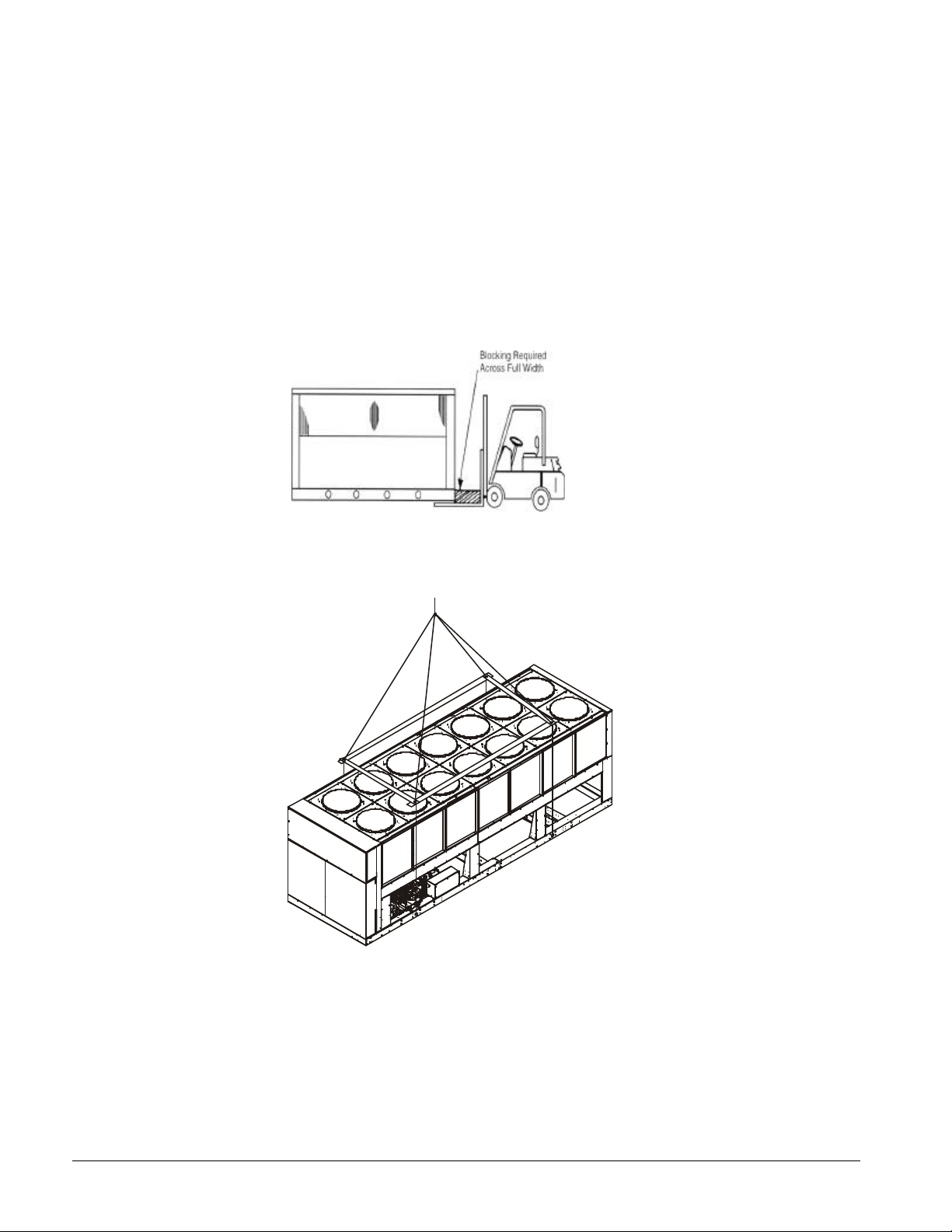
Handling
Care should be taken to avoid rough handling or shock due to impact or dropping the unit. Do not
push or pull the unit from anything other than the base, and block the pushing vehicle away from the
unit to prevent damage to the sheet metal cabinet and end frame (see Figure 1).
Never allow any part of the unit to fall during unloading or moving as this may result in serious
damage.
To lift the unit, 2½ “ (64 mm) diameter lifting holes are provided in the base of the unit. Spreader bars
and cables should be arranged to prevent damage to the condenser coils or unit cabinet (see Figure 2).
Figure 1, Suggested Pushing Method
Figure 2, Required Lifting Method
NOTES:
1. All rigging points on a unit, either 4, 6, or 8 locations, must be used. See Figure 7 through Figure 10 for number,
location, and weight at lifting points for a specific size unit. This diagram illustrates a unit with 4 mounting holes
(ALS 141 - ALS 218).
2. Crosswise and lengthwise spreader bars must be used to avoid damage to unit. Lifting cables from the unit
mounting holes up must be vertical.
3. The number of condenser sections, and fans can vary from this diagram.
4 IOMM ALS-3
Page 5

Location
Care should be taken in the location of the unit to provide proper airflow to the condenser. (See
Figure 3 through Figure 5 for required clearances).
Due to the vertical condenser coil design of the ALS chillers, it is recommended that the unit be
oriented so that prevailing winds blow parallel to the unit length, thus minimizing the wind effect on
condensing pressure and performance. It is recommended that wind baffles be installed if the unit is
installed with no protection against prevailing winds.
Using less clearances than shown in Figure 3, Figure 4, and Figure 5 will cause discharge air
recirculation to the condenser and could have a significant and detrimental effect on unit performance.
See the current version of McQuay Product Manual PM ALS for more detailed information on the
subject of air recirculation.
Service Access
Each end of the unit must be accessible after installation for periodic service work. Compressors,
filter-driers, and manual liquid line shutoff valves are accessible on each side of the unit adjacent to
the control box. High pressure and low pressure transducers are mounted on the compressor. The
cooler barrel heater thermostat is located on the cooler. Compressor microprocessor and most other
operational and equipment protection controls are located in the unit control box. The solid-state
starters with their internal electrical protection features are mounted on the base side rails adjacent to
the compressor they serve.
On all ALS units the condenser fans and motors can be removed from the top of the unit. The
complete fan/motor assembly can be removed for service. The fan blade and fan motor rain shield
must be removed for access to wiring terminals at the top of the motor.
WARNING
Disconnect all power to the unit while servicing condenser fan motors.
Failure to do so may cause bodily injury or death.
Do not block access to the sides or ends of the unit with piping or conduit. These areas must be open
for service access. Do not block any access to the control panel with a field mounted disconnect
switch.
IOMM ALS-3 5
Page 6

Clearance Requirements
Figure 3, Clearance Requirements, ALS 141-218
Notes:
1. Minimum side clearance between two units is 12 feet.
2. Unit must not be installed in a pit or enclosure that is deeper or taller than the height of the unit
unless extra clearance is provided per note 4.
3. Minimum clearance on each side is 8 feet when installed in a pit no deeper than the unit height.
4. Minimum side clearance to a side wall or building taller than the unit height is 8 feet provided no
solid wall above 6 feet is closer than 12 feet to the opposite side of the unit.
5. The evaporator can be removed from the side of the unit.
6. Do not mount electrical conduits, etc, above the side rail on either side if the unit.
7. There must be no obstruction of the fan discharge.
8. It is recommended that field supplied disconnect switches not be mounted on the unit.
6 IOMM ALS-3
Page 7
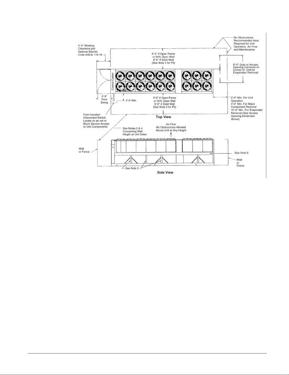
Figure 4, Clearance Requirements, ALS 245-295
Notes:
1. Minimum side clearance between two units is 12 feet.
2. Unit must not be installed in a pit or enclosure that is deeper or taller than the height of the unit
unless extra clearance is provided per note 4.
3. Minimum clearance on each side is 8 feet when installed in a pit no deeper than the unit height.
4. Minimum side clearance to a side wall or building taller than the unit height is 8 feet provided no
solid wall above 6 feet is closer than 12 feet to the opposite side of the unit.
5. The evaporator can be removed from the side of the unit.
6. Do not mount electrical conduits, etc, above the side rail on either side if the unit.
7. There must be no obstruction of the fan discharge.
8. It is recommended that field supplied disconnect switches not be mounted on the unit.
IOMM ALS-3 7
Page 8
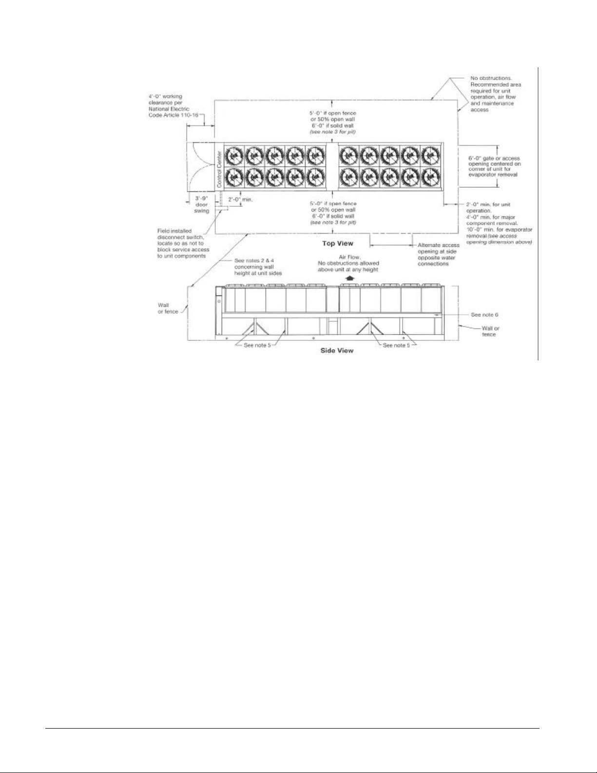
Figure 5, Clearance Requirements, ALS 325-420
Notes:
1. Minimum side clearance between two units is 12 feet.
2. Unit must not be installed in a pit or enclosure that is deeper or taller than the height of the unit
unless extra clearance is provided per note 4.
3. Minimum clearance on each side is 8 feet when installed in a pit no deeper than the unit height.
4. Minimum side clearance to a side wall or building taller than the unit height is 8 feet provided no
solid wall above 6 feet is closer than 12 feet to the opposite side of the unit.
5. The removable post for compressor service access must not be blocked at either side of the unit.
6. Do not mount electrical conduits, etc, above the side rail on either side if the unit.
7. There must be no obstruction of the fan discharge.
8. It is recommended that field supplied disconnect switches not be mounted on the unit.
8 IOMM ALS-3
Page 9

Vibration Isolators
Vibration isolators are recommended for all roof mounted installations or wherever vibration
transmission is a consideration. The following section "Lifting and Mounting Weights" contains the
location of unit lifting holes and the load at each location. Mounting holes are also dimensioned and
the bearing weight at each hole given.
Figure 6, Spring Flex Isolators
Table 1, Spring Vibration Isolators, Part Numbers
Mounting Location (See Footprint Drawings Figure 7 through Figure 10)
Model R1 R2 R3 R4 R5 R6 R7 R8 R9 R10
ALS 141-ALS 186 Isolator kit part number 350014880
Max Load 2200 2200 2600 2600 1800 1800
Spring P/N 022611901 022611901 022612000 02261200 022611800 022611800
Color Gray Gray White White Green Green
Housing P/N 022610300 022610300 022610300 022610300 022610300 022610300
ALS 190-ALS218 Isolator kit part number 350014881
Max Load 2600 2600 3000 3000 2200 2200
Spring P/N 022612000 022612000 330202101 330202101 022611901 022611901
Color White White Gold Gold Gray Gray
Housing P/N 022610300 022610300 022610300 022610300 022610300 022610300
ALS 245-ALS 295 Isolator kit part number 350014882
Max Load 2200 2200 3000 3000 2600 3000 1800 2200
Spring P/N 022611901 022611901 330202101 330202101 022612000 330202101 022611800 022611901
Color Gray Gray Gold Gold White Gold Green Gray
Housing P/N 022610300 022610300 022610300 022610300 022610300 022610300 022610300 022610300
ALS 325-ALS 420 Isolator kit part number 350014883
Max Load 2600 2600 3000 3000 2200 2200 3000 3000 2600 2600
Spring P/N 022612000 022612000 330202101 330202101 022611901 022611901 330202101 330202101 022612000 022612000
Color White White Gold Gold Gray Gray Gold Gold White White
Housing P/N 022610300 022610300 022610300 022610300 022610300 022610300 022610300 022610300 022610300 022610300
Notes:
1. The same isolators are used when the chiller is supplied with the optional copper finned condenser coils.
2. The spring is fully compressed at approximately 3900 lb. (1769 kg).
IOMM ALS-3 9
Page 10

Lifting and Mounting Weights
Figure 7, ALS 141C – ALS 186C Lifting and Mounting Locations
NOTES:
1. 2 ½ in. (63.5 mm) lifting holes at location "L" on side of base rail.
2. 1 in. (25.4 mm) mounting holes at location "R" on bottom of base rail.
L2
R2
36 (914)
BOX
CONTROL
46 (1168)
ALS
Model
141 2585 (1171) 2125 (963) 1835 (831) 1785 (809) 1230 (557) 9700 (4394) 9420 (4267) 1370 (620)
150 2570 (1164) 2205 (999) 1830 (829) 1805 (818) 1305 (591) 9880 (4476) 9550 (4326) 1370 (620)
171 2570 (1164) 2210 (1001) 1830 (829) 1810 (820) 1305 (591) 9890 (4472) 9560 (4331) 1370 (620)
186 2575 (1166) 2210 (1001) 1830 (829) 1810 (820) 1310 (593) 9900 (4485) 9570 (4335) 1370 (620)
Lifting Weight for Each
Point lb (kg)
L1 & L2 L3 & L4 R1 & R2 R3 & R4 R5 & R6
102 (2591)
R1
L1
R4
192 (4877)
161 (4089)
R3
Mounting Loads for Each Point
lb. (kg)
L4
R6
83.4
(2118)
R5
L3
Operating Wt
lb. (kg)
2 (51)
Typical Spacing
for Isolator
Mounting (6)
Shipping Wt.
lb. (kg)
Copper Fin
Figure 8, ALS 190C – ALS 218C Lifting and Mounting Locations
Add
L2 L4
R2
36 (914)
BOX
CONTROL
46 (1168)
ALS
Model
190 2915 (1320) 2230 (1010) 2010 (910) 2135 (967) 1165 (527) 10620 (4811) 10290 (4661) 1610 (730)
200 2920 (1323) 2230 (1010) 2015 (913) 2135 (967) 1165 (527) 10630 (4815) 10300 (4666) 1610 (730)
206 2940 (1332) 2310 (1046) 2000 (906) 2240 (1015) 1240 (562) 10960 (4965) 10500 (4756) 1610 (730)
218 2960 (1341) 2405 (1089) 1985 (899) 2425 (1098) 1365 (618) 11550 (5232) 10730 (4861) 1610 (730)
Lifting Weight for Each
Point lb (kg)
L1 & L2 L3 & L4 R1 & R2 R3 & R4 R5 & R6
123 (3124)
R1
L1
R4
195 (4953)
R3
Mounting Loads for Each Point
lb. (kg)
224 (5690)
R6
83.4
(2118)
R5
L3
Operating Wt
lb. (kg)
2 (51)
Typical Spacing
for Isolator
Mounting (6)
Shipping Wt.
lb. (kg)
Copper Fin
Add
10 IOMM ALS-3
Page 11
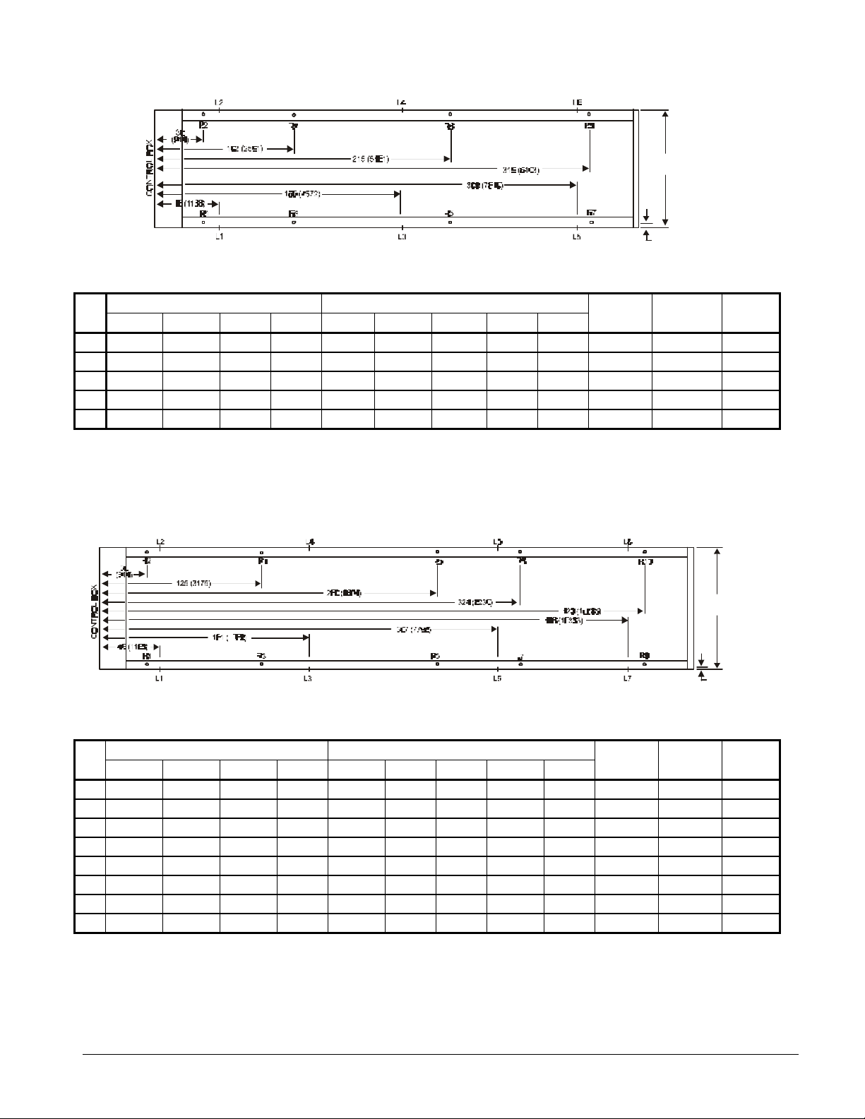
Figure 9, ALS 245C – ALS 295C Lifting and Mounting Locations
83.4
(2118)
2 (51)
Typical Spacing
for Isolator
Mounting (8)
ALS
Model
Lifting Weight for Each Point lb (kg) Mounting Loads for Each Point lb. (kg)
L1 & L2 L3 & L4 L5 L6 R1 & R2 R3 & R4 R5 & R6 R7 R8
Operating Wt
lb. (kg)
Shipping Wt.
lb. (kg)
Copper Fin
Add
245 2845 (1289) 2445 (1108) 1420 (643) 2050 (928) 1745 (790) 2240 (1015) 2030 (920) 1150 (521) 1660 (752) 14840 (6722) 14030 (6356) 2020 (915)
260 2850 (1291) 2445 (1108) 1420 (643) 2050 (928) 1745 (790) 2245 (1017) 2030 (920) 1150 (521) 1660 (752) 14850 (6727) 14040 (6360) 2020 (915)
270 2845 (1289) 2455 (1112) 1430 (648) 2060 (933) 1750 (793) 2245 (1017) 2035 (922) 1155 (523) 1665 (528) 14880 (6741) 14090 (6383) 2020 (915)
275 2850 (1291) 2455 (1112) 1430 (648) 2060 (933) 1755 (793) 2245 (1017) 2035 (922) 1155 (523) 1665 (528) 14890 (6745) 14100 (6387) 2020 (915)
295 2865 (1298) 2455 (1112) 1430 (648) 2060 (933) 1755 (793) 2250 (1019) 2035 (922) 1155 (523) 1665(528) 14900 (6750) 14110 (6392) 2020 (915)
Figure 10, ALS 325C – ALS 420C Lifting and Mounting Locations
83.4
(2118)
2 (51)
Typical Spacing
for Isolator
Mounting (10)
ALS
Model
Lifting Weight for Each Point lb (kg) Mounting Loads for Each Point lb. (kg)
L1 & L2 L3 & L4 L5 & L6 L7 & L8 R1 & R2 R3 & R4 R5 & R6 R7 & R8 R9 & R10
Operating Wt
lb. (kg)
Shipping Wt.
lb. (kg)
Copper Fin
Add
325 2625 (1189) 1895 (858) 2805 (1271) 1835 (831) 2060 (933) 1955 (886) 1485 (673) 2245 (1017) 1895 (858) 19280 (8734) 18320 (8299) 2750 (1246)
335 2625 (1189) 1895 (858) 2805 (1271) 1840 (833) 2065 (935)) 1955 (886) 1485 (673) 2245 (1017) 1895 (858) 19290 (8738) 18330 (8303) 2750 (1246)
350 2625 (1189) 1895 (858) 2805 (1271) 1840 (833) 2065 (935) 1955 (886) 1485 (673) 2245 (1017) 1895 (858) 19290 (8738) 18330 (8303) 2750 (1246)
365 2625 (1189) 1900 (861) 2805 (1271) 1840 (833) 2070 (938) 1955 (886) 1485 (673) 2245 (1017) 1895 (858) 19300 (8743) 18340 (8308) 2750 (1246)
375 2635 (1194) 1905 (863) 2815 (12750 1845 (836) 2075 (940) 1960 (888) 1490 (675) 2255 (1021) 1900 (861) 19360 (8770) 18400 (8335) 2750 (1246)
385 2640 (1196) 1905 (863) 2815 (12750 1845 (836) 2075 (940) 1965 (890) 1490 (675) 2255 (1021) 1900 (861) 19370 (8775) 18410 (8340) 2750 (1246)
400 2640 (1196) 1905 (863) 2815 (12750 1845 (836) 2075 (940) 1965 (890) 1490 (675) 2255 (1021) 1900 (861) 19370 (8775) 18410 (8340) 2750 (1246)
420 2640 (1196) 1905 (863) 2815 (12750 1845 (836) 2075 (940) 1965 (890) 1495 (677) 2260 (1024) 1920 (870) 19430 (8802) 18510 (8385) 2750 (1246)
IOMM ALS-3 11
Page 12

Water Piping
Due to the variety of piping practices, it is advisable to follow the recommendations of local
authorities. They can supply the installer with the proper building and safety codes required for a
safe and proper installation.
Basically, the piping should be designed with a minimum number of bends and changes in elevation to
keep system cost down and performance up. It should contain:
1. Vibration eliminators to reduce vibration and noise transmission to the building.
2. Shutoff valves to isolate the unit from the piping system during unit servicing.
3. Manual or automatic air vent valves at the high points of the system. Drains at the low parts in
the system. The evaporator should not be the highest point in the piping system.
4. Some means of maintaining adequate system water pressure (e.g., expansion tank or regulating
valve).
5. Water temperature and pressure indicators located at the unit to aid in unit servicing.
6. A strainer or some means of removing foreign matter from the water before it enters the pump.
The strainer should be placed far enough upstream to prevent cavitation at the pump inlet
(consult pump manufacturer for recommendations). The use of a strainer will prolong pump life
and help maintain high system performance levels.
WARNING
7. A strainer must also be placed in the supply water line just prior to the inlet of the evaporator.
This will aid in preventing foreign material from entering the evaporator and causing damage or
decreasing its performance. Care must also be exercised if welding pipe to the evaporator
connections to prevent any weld slag from entering the vessel.
8. The shell-and-tube evaporator has a thermostat and heating cable to prevent freeze-up down to 20°F (-28.8°C). It is suggested that the heating cable be wired to a separate 110V supply circuit.
As shipped from the factory, it is factory wired to the control circuit. Any water piping to the unit
must also be protected to prevent freezing.
9. If the unit is used as a replacement chiller on a previously existing piping system, the system
should be thoroughly flushed prior to unit installation and then regular chilled water analysis and
chemical water treatment is recommended immediately at equipment start-up.
10. The total water quantity in the system should be sufficient to prevent frequent "on-off" cycling.
For air-conditioning systems, system gallons equal to 7 time the flow rate is recommended.
11. In the event glycol is added to the water system, as an afterthought for freeze protection,
recognize that the refrigerant suction pressure will be lower, cooling performance less, and water
side pressure drop greater. If the percentage of glycol is large, or if propylene is employed in lieu
of ethylene glycol, the added pressure drop and loss of performance could be substantial.
12. For operations requiring the ice mode feature, logic in MicroTech will adjust the freezestat to a
pressure equivalent to 13.5°F (7.5°C) below the leaving evaporator water temperature. However, if
a different freezestat pressure value is desired, the freezestat can be manually changed through
MicroTech. Refer to the current OM ALSMICRO for additional information.
CAUTION
If a separate disconnect is used for the 110V supply to the cooler heating cable, it should be clearly
marked so that it is not accidentally shut off during cold seasons.
Prior to insulating the piping and filling the system, a preliminary leak check should be made.
Piping insulation should include a vapor barrier to prevent moisture condensation and possible
damage to the building structure. It is important to have the vapor barrier on the outside of the
insulation to prevent condensation within the insulation on the cold surface of the pipe.
12 IOMM ALS-3
Page 13

System Water Volume
It is important to have adequate water volume in the system to provide an opportunity for the chiller
to sense a load change, adjust to the change and stabilize. As the expected load change becomes
more rapid, a greater water volume is needed. The system water volume is the total amount of water in
the evaporator, air handling products and associated piping. If the water volume is too low,
operational problems can occur including rapid compressor cycling, rapid loading & unloading of
compressors, erratic refrigerant flow in the chiller, improper motor cooling, shortened equipment life
and other undesirable occurrences.
For normal comfort cooling applications where the cooling load changes relatively slowly, we
recommend a minimum system volume of seven minutes times the flow rate (gpm). For example, if the
design chiller flow rate is 400 gpm, we recommend a minimum system volume of 2800 gallons (400 gpm
X 7 minutes).
For process applications where the cooling load can change rapidly, additional system water volume is
needed. A process example would be the cooling of hot metal objects. The load would be very stable
until the hot metal is dipped into the water tank. Then, the load would increase drastically. For this
type of application, we recommend that the normal comfort cooling recommendation addressed above
plus three minutes of ballast for every 10% quick change in load. For example, if the hot metal example
load changes from a stable 50% load to an immediate 100% load for metal cooling, the recommended
system volume would increase to 8800 gallons.
System volume = {400 gpm X 7 minutes} + {(5 increments of 10% increase) X (3 minutes) X 400 gpm}
= 8800 gallons
Since there are many other factors that can influence performance, systems may successfully operate
below these suggestions. However, as the water volume decreases below these suggestions, the
possibility of problems increases.
Variable Water Flow
Variable water flow involves changing the water flow through the evaporator as the load changes.
McQuay chillers are designed for this duty provided that the rate of change in water flow is slow and
the minimum and maximum flow rates for the vessel are not exceeded.
The recommended change in water flow is listed in the table below. As the number of stages of
control increase, the slower the permissible rate of change in flow rate becomes. The ALS control
logic has timers that limit the rate of unloading or loading allowed. Slow changes allow the chiller the
opportunity to sense a change, react to the change and stabilize preventing operational problems.
ALS Size
141 to 218 2 8 10.0
245 to 295 3 12 7.5
325 to 420 4 16 5.0
For example, assume that an ALS with two compressors has a design flow of 500 gpm and the
minimum vessel flow rate of 300 gpm. The allowable amount of flow change is 200 gpm. An ALS with
two compressors has an allowable change rate of 10% of change per minute. Therefore, the maximum
rate of change recommended would be 20 gpm/minute (200 X .10).
The water flow through the vessel must remain between the minimum and maximum values listed on
Figure 19. If flow drops below the minimum allowable, large reductions in heat transfer can occur. If
the flow exceeds the maximum rate, excessive pressure drop and tube erosion can occur.
Number of
Compressors
Unloading
Steps
Maximum allowable % per
minute of flow change
IOMM ALS-3 13
Page 14

Evaporator Freeze Protection
All evaporators come equipped with thermostatically controlled resistive element heater. When power
is applied to terminals 13 and 16, the heat tape will provide freeze protection down to -20°F (-28.8°C).
However, this should not be the only method of freeze protection. Unless the evaporator is flushed
and drained as is described below in note 4, two or more of the remaining three recommendations must
be followed as part of the system design:
1. Continuous circulation of water through the piping and the heat exchanger.
2. The inclusion of glycol solution in the chilled water circuit.
3. The addition of insulation and heat to the exposed piping.
4. Draining and flushing the chiller vessel with glycol during subfreezing weather.
It is the responsibility of the installing contractor and/or on-site maintenance personnel to insure that
this additional protection is provided. Routine checks should be made to insure adequate freeze
protection is maintained.
Failure to do so may result in damage to unit components. Freeze damage is not considered a
warranty failure.
Figure 11, Typical Field Water Piping
Vent
Outlet
Drain
Vibration
Eliminator
Valved
pressure
gauge
Water
strainer
Vibration
Eliminator
Gate valve
Flow
Balancing
Switch
Protect all field piping
against freezing
valve
Gate valve
Flow Switch
A water flow switch must be mounted in the leaving water line to insure that there will be adequate
water flow to the evaporator before the unit can start. This will safeguard against slugging the
compressors on start-up. It also serves to shut down the unit in the event that water flow is
interrupted to guard against evaporator freeze-up.
A flow switch is available from McQuay under ordering number 017503300. It is a "paddle" type
switch and adaptable to any pipe size from 1" (25mm) to 8" (203mm) nominal.
Certain minimum flow rates are required to close the switch and are listed in Table 2. Installation
should be as shown in Figure 12.
Electrical connections in the unit control center should be made at terminals 62 and 63. The normally
open contacts of the flow switch should be wired between these two terminals. Flow switch contact
quality must be suitable for 24 VAC, low current (16ma). Flow switch wire must be in separate conduit
from any high voltage conductors (115 VAC and higher).
14 IOMM ALS-3
Page 15
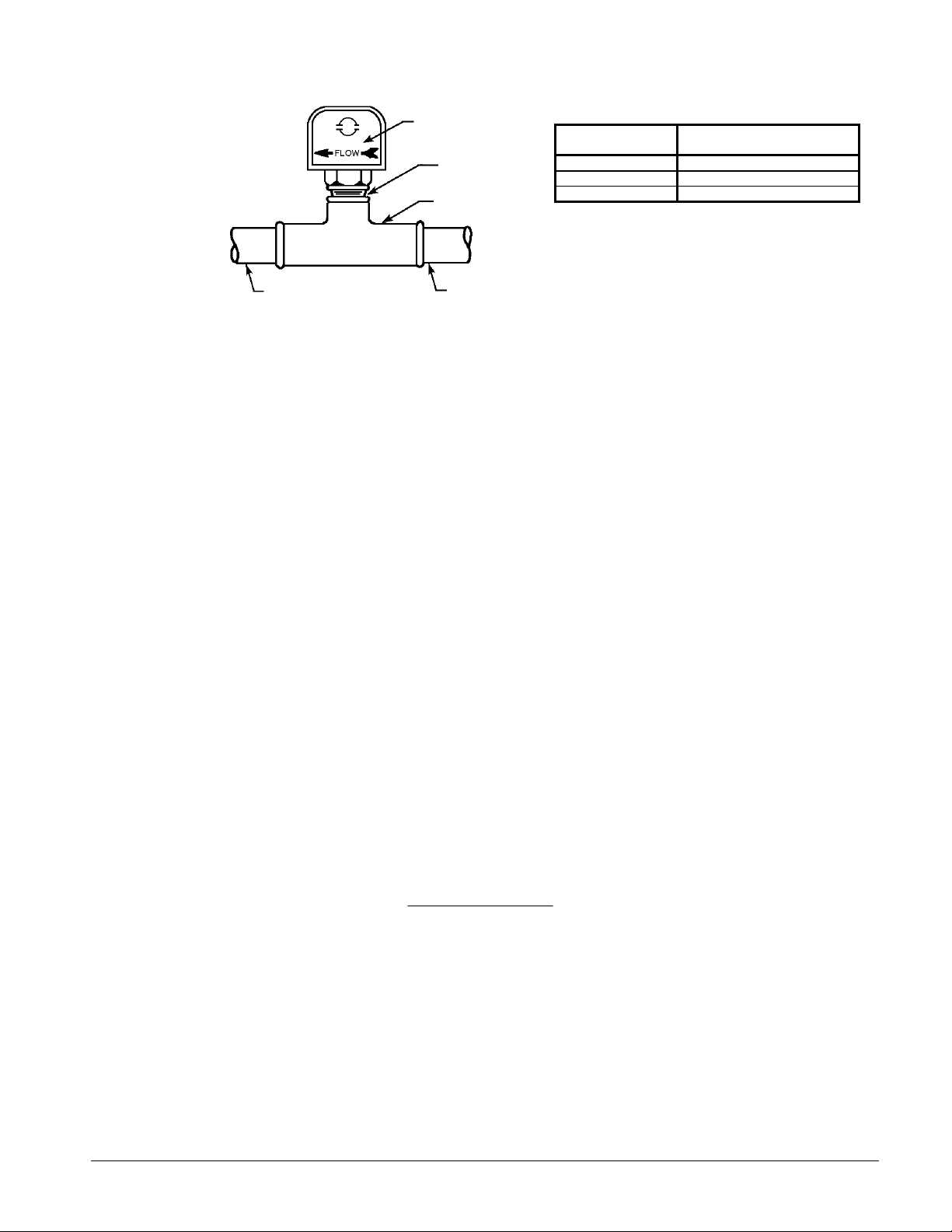
Figure 12, Flow Switch
()()(
)
Flow direction marked
on switch
1" (25mm) NPT flow
switch connection
Tee
Table 2, Switch Minimum Flow Rates
NOMINAL PIPE SIZE
INCHES (MM)
5 (127) 58.7 (3.7)
6 (152) 79.2 (5.0)
8 (203) 140 (8.8)
Note: Water pressure differential switches are not
recommended for outdoor applications.
MINIMUM REQUIRED FLOW TO
ACTIVATE SWITCH - GPM (LPS)
1 1/4" (32mm) pipe dia.
min. after switch
1 1/4" (32mm) pipe
dia. min. before switch
Water Connections
Water piping to the cooler can be brought up through the bottom of the unit or through the side
between the vertical supports. The dimensional drawings in Figure 20 through Figure 22 give the
necessary dimensions and locations for all piping connections. Evaporator piping connections face
toward the left side of the unit when looking at the control panel.
Refrigerant Charge
All units are designed for use with HCFC-22 (and are compatible with some HCFC alternatives) and are
shipped with a full operating charge. The operating charge for each unit is shown in the Physical Data
Tables. Units ordered with a remote evaporator are shipped with a unit operating charge of refrigerant
pumped down in the unit condensers. The McQuay authorized startup technician will top off the
system charge at startup.
Glycol Solutions
When using glycol anti-freeze solutions the chiller's capacity, glycol solution flow rate, and pressure
drop through the cooler may be calculated using the following formulas and tables.
Note: The procedure below does not specify the type of glycol. Use the derate factors found in Table
3 for corrections when using propylene glycol and those in Table 4 for ethylene glycol.
1. Capacity - Cooling capacity is reduced from that with plain water. To find the reduced value,
multiply the chiller’s water system tonnage by the capacity correction factor to find the chiller’s
capacity when using glycol.
2. Flow - To determine flow (or delta-T) knowing delta-T (or flow) and capacity:
GPM−=
24
factorflowtons
TDelta
3. Pressure drop - To determine pressure drop through the cooler, when using glycol, enter the
water pressure drop curve at the water flow rate. Multiply the water pressure drop found there by
the PD factor to obtain corrected glycol pressure drop.
4. To determine glycol system kW, multiply the water system kW by factor called Power.
Test coolant with a clean, accurate glycol solution hydrometer (similar to that found in service
stations) to determine the freezing point. Obtain percent glycol from the freezing point table below.
On glycol applications the supplier normally recommends that a minimum of 25% solution by weight
be used for protection against corrosion.
IOMM ALS-3 15
Page 16

CAUTION
Do not use automotive grade antifreeze. Industrial grade glycols must be used. Automotive antifreeze
contains inhibitors that will cause plating on the copper tubes within the chiller evaporator. The type and
handling of glycol used must be consistent with local codes.
Table 3, Propylene Glycol
FREEZE
%
POINT.
P.G.
oFo
C
10 26 -3 0.987 0.992 1.010 1.068
20 19 -7 0.975 0.985 1.028 1.147
30 9 -13 0.962 0.978 1.050 1.248
40 -5 -21 0.946 0.971 1.078 1.366
50 -27 -33 0.965 0.965 1.116 1.481
Remote Evaporator
General
The multiple compressor ALS air-cooled chillers are available with the evaporator shipped loose for
remote mounting. This allows the main unit to be installed outdoors to save interior room and
eliminates the need for anti-freeze solutions and heat tracing of chilled water lines since the chilled
water system is indoors. There are some general guidelines to review before proceeding:
1. R-22 only.
2. Maximum line length of 50 ft (15 m) and Total Equivalent Length (TEL) of 120 ft (37 m).
3. Evaporator not more than 6 ft (1.8 m) above the compressor or 16 ft (5 m) below compressor.
4. No underground piping.
CAP POWER FLOW PD
Table 4, Ethylene Glycol
FREEZE
%
E.G.
POINT.
oFo
10 26 -3 0.991 0.996 1.013 1.070
20 18 -8 0.982 0.992 1.040 1.129
30 7 -14 0.972 0.986 1.074 1.181
40 -7 -22 0.961 0.976 1.121 1.263
50 -28 -33 0.946 0.966 1.178 1.308
CAP POWER FLOW PD
C
5. No hot gas bypass.
6. Units with remote evaporator are not included in the ARI Certification Program.
The remote evaporator is shipped separately, ready for quick and easy installation at the job site. All
refrigerant accessories such as liquid-vapor line shut-off valves, replaceable core filter-driers, liquid
line solenoid valves, electronic expansion valves, and sightglasses are already included on the ALS
condensing unit. The evaporator is equipped with entering and leaving chilled water temperature
sensor wells. The sensors are pre-wired to the ALS unit with 75 feet long sensor leads and must be
field connected to the evaporator thermowells. Suction pressure transducers and temperature sensors
must also be relocated to the evaporator. ALS units are factory charged with a full unit charge
pumped down into the condensers. Field piping must be leak tested, evacuated and charged during
installation. Do not exceed 150 psig test pressure unless the unit is blanked off from the piping.
Performance Derate Factors
All performance tables and adjustment factors found in the current version of the Air-Cooled Screw
Chiller catalog (PM ALS-x) are applicable for remote evaporator installations. However, a performance
derate must be applied to the R-22 performance data due to additional pressure drops in the suction
and liquid lines which cause a loss of compressor performance. These derates are based on a suction
line pressure drop equivalent of approximately 2°F (1°C) change in saturation temperature.
For R-22 applications:
Capacity = Tons (kW) x 0.97 Power = Compressor kW x 0.99
16 IOMM ALS-3
Page 17

Refrigerant Piping
General
Careful design of the refrigerant piping is necessary for efficient system operation. The refrigerant
piping should be designed for a low refrigerant pressure drop to obtain maximum capacity and
efficiency while maintaining adequate velocity. Lines should slope in the direction of flow to assure
good oil return to the compressors. Cost considerations favor keeping line sizes as small as possible
while not exceeding acceptable pressure drops in order to maintain unit performance.
NOTE
All refrigerant piping must be reviewed and approved by McQuay Application
Engineers prior to order entry and will be verified by McQuay startup technicians.
Equivalent Line Lengths
Recommended refrigerant line sizes are based on equivalent line lengths of straight pipe, that is, a
combination of straight pipe, fittings and valves. The pressure drop through valves and fittings is
determined by establishing the equivalent straight length of pipe of the same size with the same
friction loss. The "Total Equivalent Length" is the sum of the "Lineal Line Length" and the
appropriate "Valve and Fitting Losses in Equivalent Feet of Pipe for Field Supplied Piping" given in
Table 5
Table 5, Fitting Equivalent Feet of Pipe
Line Size (in.) Angle Valve Globe Valve 90° Std. Radius Elbow 90° Long Radius Elbow
1 1/8 12 29 2.6 1.7
1 3/8 15 38 3.3 2.3
1 5/8 18 43 4.0 2.6
2 1/8 24 55 5.0 3.3
2 5/8 29 69 6.0 4.1
3 1/8 35 84 7.5 5.0
Location and Arrangement
Refrigerant lines should be as short and direct as possible to minimize tubing and fittings. Long
radius elbows must be used (except for traps) to minimize the pressure drops. Traps should be as
short as possible to minimize oil accumulation. Refrigerant piping should be arranged so that normal
inspection of the equipment is not hindered. Adequate clearance should be provided between
refrigerant piping and adjacent walls for insulation. Piping should be run so that it does not interfere
with compressor service access, passages or obstruct headroom, windows and doors. Suction line
hangers must be sized and located to support the weight of the piping in accordance with good piping
practice.
Horizontal portions of the suction lines must be downward sloping toward the compressors. Slope all
piping in the direction of flow. Vertical portions of the suction lines must be sized for oil return at
minimum compressor load.
Note: Double section risers must not be utilized on any circuit. Traps must be provided as shown on
Figure 13 and Figure 14.
Suction Line Sizing
Pressure drop in the suction line reduces system capacity and efficiency because it forces the
compressor to operate at lower suction pressure. The suction line should be sized for a pressure drop
approximately equivalent of 2°F (1°C) change in saturation temperature. For suction line sizing see
Table 7 and table 8. For applications with the evaporator below the ALS unit, the vertical section of
the suction lines must be sized to return oil to the compressors at the minimum compressor capacity
step.
IOMM ALS-3 17
Page 18

Example of Suction Line Size Calculation
ALS150C condensing unit with refrigerant R-22
Evaporator located 5 feet below the ALS compressor
Lineal length of horizontal suction line is 25 feet
Suction line requires 7 long radius (90°) elbows; 3 in the horizontal, 4 in the riser
From Table 6, the nominal circuit capacities for circuit 1 and 2 are 65 and 80 tons respectively
Total lineal suction line length = 30 feet each circuit (25 feet horizontal plus 5 feet vertical riser).
For the first try, assume that the total equivalent suction line length is twice the lineal suction
line length.
Therefore the estimated total equivalent suction line length = 60 feet
From Table 7 and Table 8, For nominal circuit capacities of 65 & 80 tons and total equivalent line
length of 60 ft, the suction line size = 2 5/8" for horizontal lines and 2 1/8" for vertical lines.
From Table 5, Fitting loss for 2 5/8" long radius (90°) elbow = 4.1 ft, and 3.3 ft for the 2 1/8 elbows.
Therefore fitting loss in equivalent feet of pipe for (3) 2 5/8" long radius (90°) elbow = 12.3 ft, and
13.2 ft for (4) 2 1/8" elbows.
Therefore the actual equivalent suction line length = 30 + 12.3 + 13.2 = 55.5 feet
From and Table 8, For nominal circuit capacities of 65 & 80 tons and equivalent line length of 55.5 ft
the suction line size is correct.
Table 6, ALS 141C-420C Nominal Circuit Capacities
ALS Model
141 65 (229) 65 (229) - 150 65 (229) 80 (262) - 171 80 (262) 80 (262) - 186 80 (262) 95 (334) - 190 80 (262) 95 (334) - 200 95 (334) 95 (334) - 206 95 (334) 95 (334) - 218 95 (334) 95 (334) - 245 65 (229) 80 (262) 80 (262) 260 80 (262) 80 (262) 80 (262) 270 80 (262) 80 (262) 95 (334) 275 80 (262) 95 (334) 95 (334) 295 95 (334) 95 (334) 95 (334) 325 65 (229) 65 (229) 80 (262) 80 (262)
335 65 (229) 80 (262) 80 (262) 80 (262)
350 80 (262) 80 (262) 80 (262) 80 (262)
365 80 (262) 80 (262) 80 (262) 95 (334)
375 80 (262) 80 (262) 95 (334) 95 (334)
385 80 (262) 95 (334) 95 (334) 95 (334)
400 95 (334) 95 (334) 95 (334) 95 (334)
420 95 (334) 95 (334) 95 (334) 95 (334)
Circuit 1 Circuit 2 Circuit 3 Circuit 4
Tons (kW) Tons (kW) Tons (kW) Tons (kW)
Table 7, Vertical Upflow Suction Line Sizes
Nominal Circuit
Capacity
Tons (kW)
65 (229)
80 (262)
95 (334)
Equivalent Line Length Ft (m) Suction Line Size (in.)
Vertical Upflow Suction Lines
40 (12) 2 1/8
75 (23) 2 1/8
40 (12) 2 1/8
75 (23) 2 1/8
40 (12) 2 5/8
75 (23) 2 5/8
18 IOMM ALS-3
Page 19
Table 8, Horizontal and Vertical Downflow Suction Line Sizes
Capacity
Tons (kW)
65 (229) 75 (23) 2 5/8
80 (262) 75 (23) 2 5/8
95 (334) 75 (23) 3 1/8
Vertical Downflow and Horizontal Suction LinesNominal Circuit
Equivalent Line Length Ft (m) Suction Line Size, in.
40 (12) 2 5/8
115 (35) 2 5/8
40 (12) 2 5/8
115 (35) 3 1/8
40 (12) 2 5/8
115 (35) 3 1/8
Liquid-Vapor Lines
The liquid-vapor line from the ALS condensing unit to the evaporator liquid connection is not a
conventional liquid line since it carries both liquid and vapor. The compressors on the ALS units
utilize a liquid cooled motor and an economizer. Therefore the expansion valve which feeds the full
flow of liquid refrigerant into the compressor for motor cooling is mounted in the liquid line between
the condenser sub-cooling coil and the compressor inlet, not at the evaporator inlet. The liquid-vapor
line to the evaporator is a low pressure line downstream of the expansion valve and the size is slightly
larger than a normal liquid line. For liquid line sizing see Table 9 and Table 10.
Table 9, Vertical Upflow Liquid-Vapor Line Sizes
Capacity
Tons (kW)
65 (229)
80 (262)
95 (334)
Equivalent Line Length
Vertical Upflow Liquid-Vapor LinesNominal Circuit
Ft (m)
40 (12) 1 3/8
75 (23) 1 3/8
40 (12) 1 3/8
75 (23) 1 3/8
40 (12) 1 5/8
75 (23) 1 5/8
Liquid-Vapor Line Size
o.d (in.)
Table 10, Horizontal and Vertical Downflow Liquid-Vapor Line Sizes
Capacity
Tons (kW)
65 (229) 75 (23) 1 3/8
80 (262) 75 (23) 1 5/8
95 (334) 75 (23) 1 5/8
Vertical Downflow and Horizontal Liquid-Vapor LinesNominal Circuit
Equivalent Line Length
Ft (m)
40 (12) 1 3/8
115 (35) 1 3/8
40 (12) 1 3/8
115 (35) 1 5/8
40 (12) 1 5/8
115 (35) 1 5/8
Liquid-Vapor Line Size
o.d (in.)
Figure 13, Evaporator Above ALS Unit
Evaporator
Trap
ALS Unit
Suction Line
IOMM ALS-3 19
Page 20

Figure 14, Evaporator Below ALS Unit
ALS Unit
Suction Line
Evaporator
Trap
NOTE: Keep the trap width at a minimum to avoid trapping excessive oil.
Insulation
All piping joints and fittings must be thoroughly leak tested before insulation is applied. Suction lines
must be insulated and should not be installed underground. Suction line insulation must be selected
to prevent condensation under local ambient conditions with the lines at 40°F to 50°F (4.4°C to 10°C)
operating temperatures. The liquid-vapor lines will operate at 40°F to 60°F (4.4°C to 15.6°C) and must
also be insulated to prevent sweating and heat gain.
20 IOMM ALS-3
Page 21

Startup Procedures
NOTE: McQuayService or a factory authorized McQuay service agent must do initial start-up and
commissioning.
Filter Driers
Following an initial 24 hour operation the pressure drop across the replaceable core filter-drier should
be checked. If this pressure drop exceeds the values given in Table 11 at the various load conditions
the filter drier cores must be replaced. Also if the moisture indicating sight glass shows a wet system
condition after 24 hours of operation the filter cores must be changed. This should remove any
contaminants introduced during field piping. The filter drier cores must also be changed anytime the
system is opened for servicing.
Table 11, Filter Drier Pressure Drop
Percent Circuit
Loading (%)
100 7 (48.3)
75 5 (34.5)
50 3 (20.7)
25 3 (20.7)
Refrigerant and Oil Charge
The relative position of the ALS unit and the evaporator and the distance between them plays a
critical role in determining suction and liquid line sizes and the field refrigerant and oil charges. ALS
units with the remote evaporator option are shipped with a unit operating charge of refrigerant and oil.
It will be necessary to evacuate the evaporator and field installed line and top off the charge See
Table 12 for refrigerant charge for suction and liquid-vapor lines. McQuay Service will supply and
add additional oil as required. The correct oil is Planetelf ACD68AW, McQuay Part No. 735030439 (5
gal.), 735030438 (1 gal.).
Maximum Recommended Pressure Drop Across Filter Drier
psig (kPa)
Charging Procedure
The calculated refrigerant charge must be added through the factory supplied charging valve located
on the liquid-vapor line coming out of the compressor. Sufficient charge must be added to clear the
liquid line sight glass located at the outlet of the condenser. Add an extra 10 lb. of refrigerant after the
sight glass is clear.
Table 12, Refrigerant Charge for Suction and Liquid-Vapor Lines
Lineal Tubing
Length
ft (m)
10 (3) 2 5/8 0.51 (0.23) 1 5/8 5.0 (2.3)
20 (6) 2 5/8 1.02 (0.46) 1 5/8 10.0 (4.5)
30 (9) 2 5/8 1.53 (0.69) 1 5/8 15.0 (6.8)
40 (12) 2 5/8 2.04 (0.92) 1 5/8 20.0 (9.0)
Suction Line Refrigerant Charge
lb (kg)
Line (in.) R-22 Line (in.) R-22
2 1/8 0.33 (0.15) 1 3/8 3.6 (1.6)
3 1/8 0.71 (0.32)
2 1/8 0.66 (0.30) 1 3/8 7.2 (3.3)
3 1/8 1.42 (0.64)
2 1/8 0.99 (0.45) 1 3/8 10.8 (4.9)
3 1/8 2.13 (0.96)
2 1/8 1.32 (0.60) 1 3/8 14.4 (6.5)
3 1/8 2.84 (1.29)
Notes:
1. The only approved oil is that identified on the label attached to the compressors. All POE oils are
hygroscopic and care should be exercised in handling the oil to avoid absorption and retention of
moisture.
2. Do not leave the oil container open for more than a minute while charging oil. Do not use oil that
has not been properly sealed and stored.
3. Charge must never be added through the compressor suction line
Liquid-Vapor Line Refrigerant Charge
lb (kg)
IOMM ALS-3 21
Page 22
Dimensions
Use the ALS dimension drawings Figure 20 through Figure 22 for the ALS with remote evaporator.
The refrigerant connections are located approximately where the refrigerant connections to the unit
mounted evaporator are on a packaged chiller. The remote evaporator dimensions are Figure 15
through Figure 18.
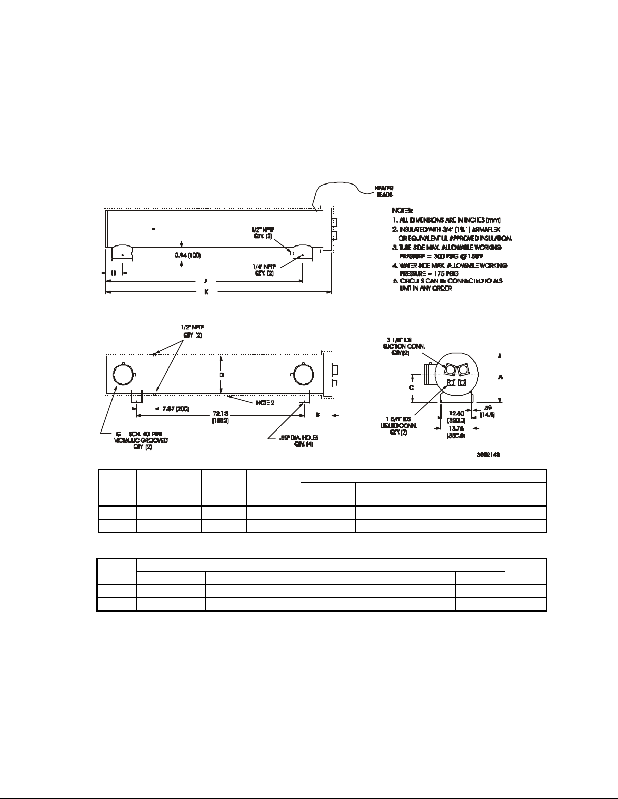
Dimensions, Remote Evaporator
Figure 15, Evaporator for ALS 141 - ALS 200
ALS
Model
141 CDE350332801 34 (128) 1.4 (40.0) 934 (424) 635 (288) 34 (15.4) 34 (15.4)
150-200 CDE350332901 40 (150) 1.8 (52.4) 1127 (512) 758 (343) 45 (20.4) 45 (20.4)
Model
141 94.6 (2403) 17.8 (452) 11.0 (279) 10.2 (259) 12.8 (325) 6.4 (163) 85.2 (2164) 5 (152)
150-200 95.5 (2426) 18.4 (467) 12.0 (305) 10.2 (259) 14.0 (356) 6.8 (173) 84.0 (2134) 8 (203)
Evaporator
Model
Overall Dimensions in. (mm)ALS
Length "K" Height "A" "B" "C" "D" "H" "J"
Water
Volume
gal. (l)
Refrigerant
Volume
cu. ft. (L)
Unit Weights lb. (kg) R-22 Operating Charge lb. (kg)
Operating Shipping Circuit 1 Circuit 2
Conn.
"G"
22 IOMM ALS-3
Page 23
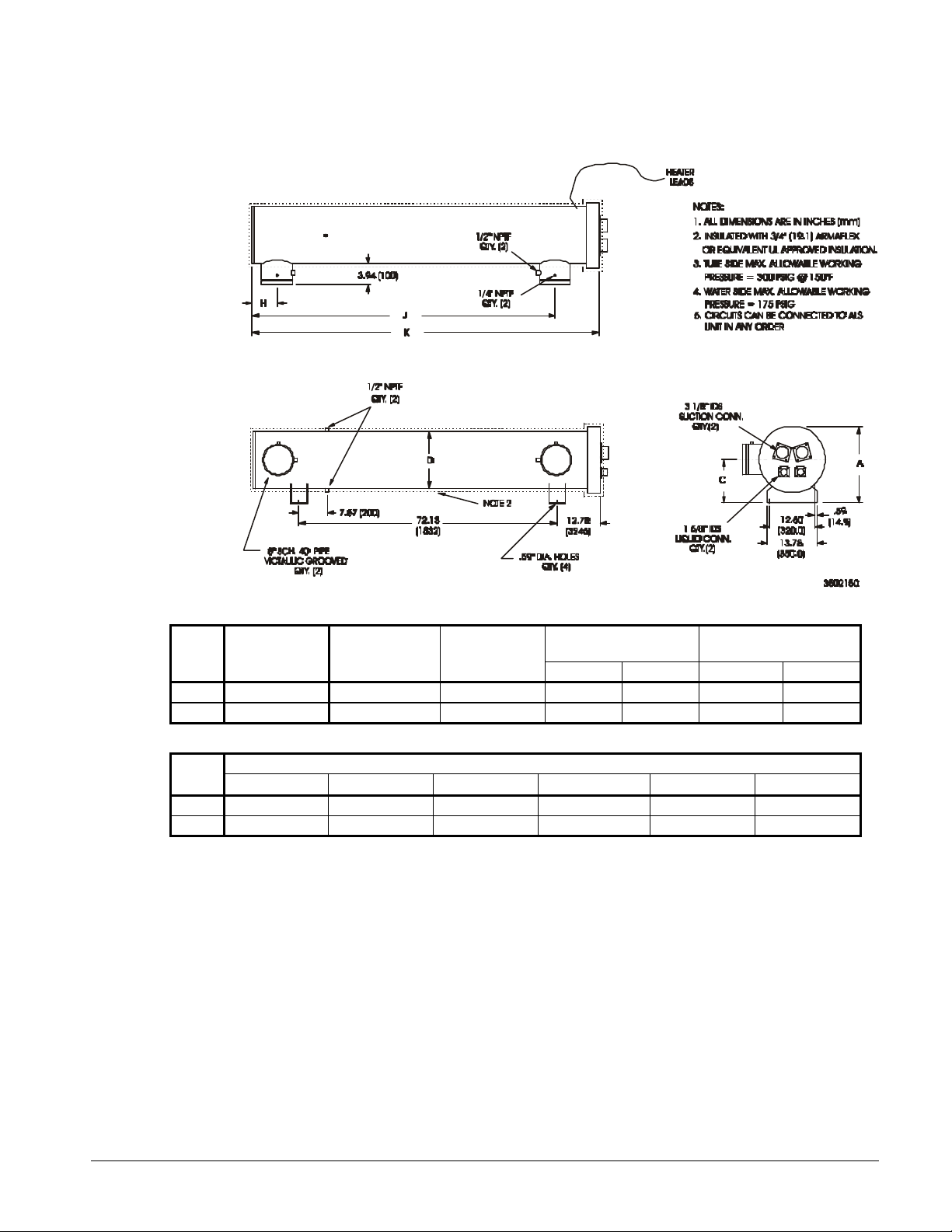
Figure 16, Evaporator for ALS 206 - ALS 218
ALS
Model
206 CDE350281651 55 (208) 2.4 (67.9) 1464 (665) 943 (428) 57 (25.8) 57 (25.8)
218 CDE350282101 98 (373) 2.8 (79.2) 2028 (921) 1121 (509) 68 (30.9) 68 (30.9)
Model
206 21.3 (542) 12.1 (307) 16.0 (406) 6.9 (176) 84.5 (2149) 96.7 (2459)
218 23.6 (601) 12.4 (315) 20.0 (508) 9.2 (235) 86.6 (2202) 99.7 (2533)
Evaporator
Model
A C D H J K
Water Volume
gal. (l)
Refrig Volume
cu. ft. (l)
Dimensional DataALS
Weights lb. (kg)
Operating Shipping Circuit 1 Circuit 2
R-22 Opn Charge lb.
(kg)
IOMM ALS-3 23
Page 24

Figure 17, Evaporator for ALS 245 - ALS 295
Evaporator
Model
245-260 CDE350282111 98 (371) 2.91 (82.3) 2035 (924) 1130 (513) 47 (21) 47 (21) 47 (21)
270-295 CDE350282121 94 (357) 3.3 (93.4) 2068 (939) 1174 (533) 53 (24) 53 (24) 53 (24)
Model
Water
Volume
gal. (l)
Refrig
Volume
cu. ft. (l)
Weights lb. (kg)
Operating Shipping
R-22 Operating Charge lb.
(kg)ALS
Circuit1Circuit
Circuit 3
2
24 IOMM ALS-3
Page 25
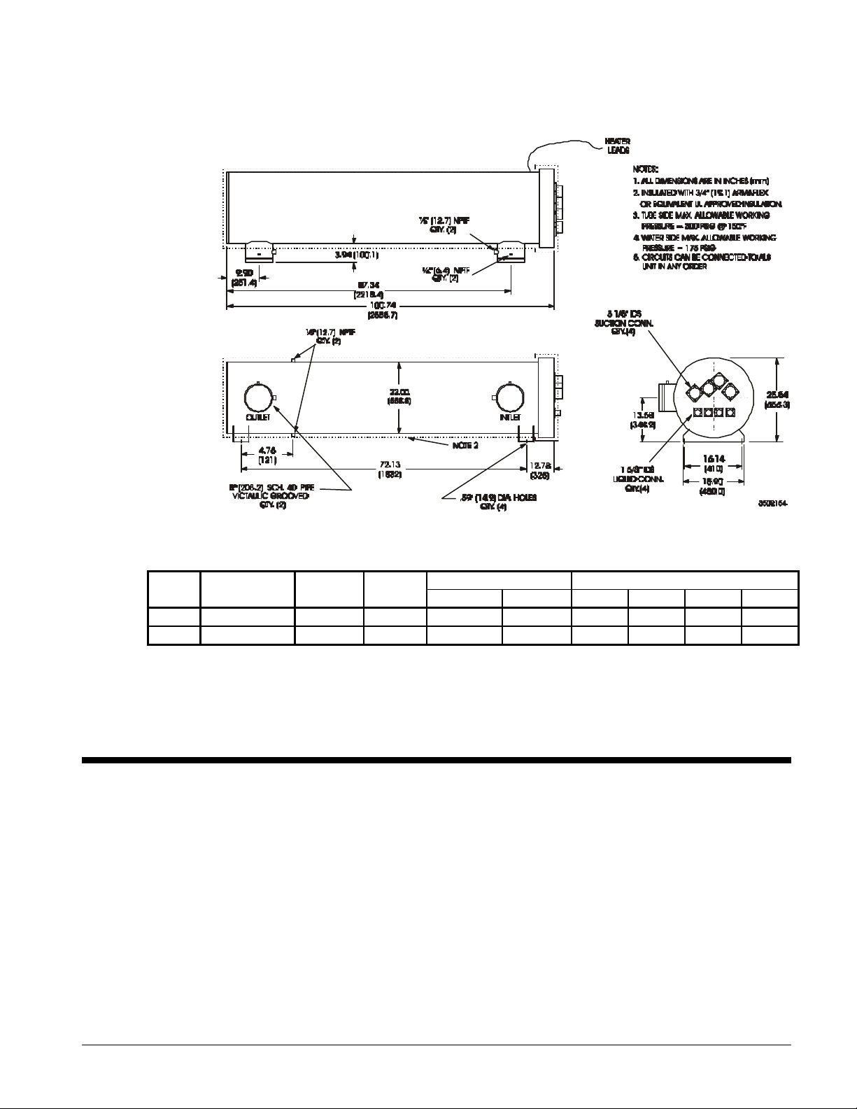
Figure 18, Evaporator for ALS 325 - ALS 420
Evaporator
Model
325-400 CDE350283101 115 (435) 4.1 (116) 2529 (1148) 1423 (646) 49 (22) 49 (22) 49 (22) 49 (22)
420 CDE350283111 110 (416) 4.7 (133( 2575 (1169) 1484 (674) 56 (25) 56 (25) 56 (25) 56 (25)
Model
Water Vol.
gal. (l)
Refrig Vol.
cu. ft. (l)
Operating Shipping Circuit 1 Circuit 2 Circuit 3 Circuit 4
Water Flow and Pressure Drop
The chilled water flow through the evaporator should be adjusted to meet specified conditions. The
flow rates must fall between the minimum and maximum values shown in. Flow rates below the
minimum values shown will result in laminar flow that will reduce efficiency, cause erratic operation of
the electronic expansion valve and could cause low temperature cutouts. On the other hand flow rates
exceeding the maximum values shown can cause erosion on the evaporator water connections and
tubes.
Measure the chilled water pressure drop through the evaporator at field installed pressure taps. It is
important not to include valve or strainer pressure drop in these readings.
Weights lb. (kg) R-22 Operating Charge lb. (kg)ALS
IOMM ALS-3 25
Page 26

Figure 19, Evaporator Pressure Drops
ALS 420
ALS 141
ALS 150-200
ALS 206
ALS 218-260
ALS 270-295
ALS 325-400
Table 13, Minimum/Maximum Flow Rates
ALS
Minimum
Unit
Size
141 187 4.0 498 24.2 275 395 4.2 1052 37.8
150 210 4.2 559 28.5 295 413 4.6 1100 41.9
171 234 5.2 623 35.3 325 445 3.9 1186 34.8
186 255 6.1 680 41.9 335 463 4.2 1235 38.1
190 260 6.4 692 43.4 350 484 4.7 1291 42.1
200 276 7.2 737 49.0 365 498 5.0 1328 44.8
206 285 7.5 761 50.4 375 531 5.8 1417 51.9
218 307 5.0 818 36.8 385 546 6.0 1457 55.2
245 339 5.9 903 43.6 400 565 6.6 1506 59.4
260 360 6.7 960 49.4 420 609 8.8 1623 76.2
270 380 3.8 1012 34.7
Flow
gpm
Pressure
Drop ft.
Maximum
Flow gpm
Pressure
Drop ft.
ALS
Unit
Size
Minimum
Flow gpm
Pressure
Drop ft.
Maximum
Flow gpm
Pressure
Drop ft.
26 IOMM ALS-3
Page 27

Physical Data
Table 14, Physical Data, ALS 141C – ALS 186C
DATA 141C 150C 171C 186C
BASIC DATA
Unit Cap. @ ARI Conditions, tons
(kW)
Unit Operating Charge R-22, lbs (kg) 140 (63.5) 140 (63.5) 140 (63.5) 150 (68.1) 150 (68.1) 150 (68.1) 150 (68.1) 160 (72.6)
Cabinet Dimensions
L x W x H, in. (mm)
Unit Operating Weight, lbs. (kg) 9700 (4395) 9880 (4475) 9890 (4480) 9900 (4485)
Unit Shipping Weight, lbs (kg) 9420 (4270) 9550 (4325) 9560 (4330) 9570 (4335)
COMPRESSORS, SCREW, SEMI-HERMETIC
Nominal Capacity, tons (kW) 65 (230) 65 (230) 65 (230) 80 (280) 80 (280) 80 (280) 80 (280) 95 (335)
CONDENSERS, HIGH EFFICIENCY FIN AND TUBE TYPE WITH INTEGRAL SUBCOOLER
Coil Face Area, ft2. (m2) 115.6 (10.7) 115.6 (10.7) 115.6 (10.7) 115.6 (10.7) 115.6 (10.7) 115.6 (10.7) 115.6 (10.7) 115.6 (10.7)
Finned Height x Finned Length
ft. (mm)
Fins Per Inch x Rows Deep 16 x 3 16 x 3 16 x 3 16 x 3 16 x 3 16 x 3 16 x 3 16 x 3
CONDENSER FANS, DIRECT DRIVE PROPELLER TYPE
No. of Fans -- Fan Diameter, in. (mm) 10 - 28 (711) 10 - 28 (711) 12 - 28 (711) 12 - 28 (711)
No. of Motors -- hp (kW) 10 - 1.5 (1.1) 10 - 1.5 (1.1) 12 - 1.5 (1.1) 12 - 1.5 (1.1)
Fan & Motor RPM, 60Hz 1140 1140 1140 1140
60 Hz Fan Tip Speed, fpm 8357 8357 8357 8357
60 Hz Total Unit Airflow, ft3/min 90200 90200 108240 108240
EVAPORATOR, DIRECT EXPANSION
Shell Dia.- Length
in.(mm) - in. (mm)
Evaporator R-22 Charge lbs (kg) 34 (15.4) 34 (15.4) 45 (20.4) 45 (20.4) 45 (20.4) 45 (20.4) 45 (20.4) 45 (20.4)
Water Volume, gallons (liters) 34 (129) 40 (151) 40 (151) 40 (151)
Max. Water Pressure, psi (kPa) 152 (1048) 152 (1048) 152 (1048) 152 (1048)
Max. Refrigerant Pressure, psi (kPa) 300 (2068) 300 (2068) 300 (2068) 300 (2068)
Ckt 1 Ckt 2 Ckt 1 Ckt 2 Ckt 1 Ckt 2 Ckt 1 Ckt 2
124.5 (436) 139.7 (489) 155.8 (545) 170 (595)
228.7 x 83.4 x 92.5
(5809 x 2118 x 2350)
80 x 208
(2032 x 5283)
(2032 x 5283)
12.75 – 94.6
(324 - 2403)
80 x 208
228.7 x 83.4 x 92.5
(5809 x 2118 x 2350)
80 x 208
(2032 x 5283)
Table 15, Physical Data, ALS 190C – ALS 218C
DATA 190C 200C 206C 218C
BASIC DATA
Unit Cap. @ ARI Conditions, tons
(kW)
Unit Operating Charge R-22, lbs (kg) 170 (77.0) 180 (81.5) 180 (81.5) 180 (81.5) 185 (83.8) 185 (83.8) 210 (95.1) 210 (95.1)
Cabinet Dimensions,
L x W x H, in. (mm)
Unit Operating Weight, lbs. (kg) 10620 (4810) 10630 (4815) 10960 (4965) 11550 (5230)
Unit Shipping Weight, lbs (kg) 10290 (4660) 10300 (4665) 10500 (4755) 10730 (4860)
COMPRESSORS, SCREW, SEMI-HERMETIC
Nominal Capacity, tons (kW) 80 (280) 95 (335) 95 (335) 95 (335) 95 (335) 95 (335) 95 (335) 95 (335)
CONDENSERS, HIGH EFFICIENCY FIN AND TUBE TYPE WITH INTEGRAL SUBCOOLER
Coil Face Area, ft2. (m2) 135.0 (12.5) 135.0 (12.5) 135.0 (12.5) 135.0 (12.5) 135.0 (12.5) 135.0 (12.5) 135.0 (12.5) 135.0 (12.5)
Finned Height x Finned Length
ft. (mm)
Fins Per Inch x Rows Deep 16 x 3 16 x 3 16 x 3 16 x 3 16 x 3 16 x 3 16 x 3 16 x 3
CONDENSER FANS, DIRECT DRIVE PROPELLER TYPE
No. of Fans -- Fan Diameter, in. (mm) 14 - 28 (711) 14 - 28 (711) 14 - 28 (711) 14 - 28 (711)
No. of Motors -- hp (kW) 14 - 1.5 (1.1) 14 - 1.5 (1.1) 14 - 1.5 (1.1) 14 - 2.0 (1.5)
Fan & Motor RPM, 60Hz 1140 1140 1140 1140
60 Hz Fan Tip Speed, fpm 8357 8357 8357 8357
60 Hz Total Unit Airflow, ft3/mon 126280 126280 126280 138908
EVAPORATOR, DIRECT EXPANSION
Shell Dia. -- Length
in.(mm) - in. (mm)
Evaporator R-22 Charge lbs (kg) 45 (20.4) 45 (20.4) 45 (20.4) 45 (20.4) 57 (25.8) 57 (25.8) 68 (30.8) 68 (30.8)
Water Volume, gallons (liters) 40 (151) 40 (151) 55 (208) 98 (371)
Max. Water Pressure, psi (kPa) 152 (1048) 152 (1048) 152 (1048) 152 (1048)
Max. Refrigerant Pressure, psi (kPa) 300 (2068) 300 (2068) 300 (2068) 300 (2068)
Ckt 1 Ckt 2 Ckt 1 Ckt 2 Ckt 1 Ckt 2 Ckt 1 Ckt 2
173.1 (606) 184.2 (645) 190.3 (666) 204.4 (715)
263.4 x 83.4 x 92.5
(6690 x 2118 x 2350)
80 x 243
(2032 x 6172)
(2032 x 6172)
14.0 – 95.5
(356 - 2425)
80 x 243
263.4 x 83.4 x 92.5
(6690 x 2118 x 2350)
80 x 243
(2032 x 6172)
ALS MODEL NUMBER
80 x 208
(2032 x 5283)
14.0 – 95.5
(356 - 2425)
ALS MODEL NUMBER
80 x 243
(2032 x 6172)
14.0 – 95.5
(356 - 2425)
228.7 x 83.4 x 92.5
(5809 x 2118 x 2350)
80 x 208
(2032 x 5283)
263.4 x 83.4 x 92.5
(6690 x 2118 x 2350)
80 x 243
(2032 x 6172)
(2032 x 5283)
14.0 – 95.5
(356 - 2425)
(2032 x 6172)
16.0 – 96.8
(406 - 2459)
80 x 208
80 x 243
228.7 x 83.4 x 92.5
(5809 x 2118 x 2350)
80 x 208
(2032 x 5283)
263.4 x 83.4 x 92.5
(6690 x 2118 x 2350)
80 x 243
(2032 x 6172)
(2032 x 5283)
14.0 – 95.5
(356 - 2425)
(2032 x 6172)
20.0 – 99.7
(508 - 2532)
80 x 208
80 x 243
IOMM ALS-3 27
Page 28

Table 16, Physical Data, ALS 245C – ALS 270C
DATA 245C 260C 270C
CKT. 1 CKT. 2 CKT. 3 CKT. 1 CKT. 2 CKT. 3 CKT. 1 CKT. 2 CKT. 3
BASIC DATA
Unit Cap. @ ARI Conditions, tons
225.7 (790) 239.8 (839) 253.0 (886)
(kW)
Unit Operating Charge R-22, lbs (kg) 140 (63.5) 150 (68.1) 150 (68.1) 150 (68.1) 150 (68.1) 150 (68.1) 150 (68.1) 150 (68.1) 160 (72.6)
Cabinet Dimensions, L x W x H, in.
(mm)
355 x 83.4 x 94.5
(9017 x 2118 x 2400)
Unit Operating Weight, lbs. (kg) 14840 (6725) 14850 (6730) 14880 (6740)
Unit Shipping Weight, lbs (kg) 14030 (6355) 14040 (6360) 14090 (6385)
COMPRESSORS, SCREW, SEMI-HERMETIC
Nominal Capacity, tons (kW) 65 (230) 80 (280) 80 (280) 80 (280) 80 (280) 80 (280) 80 (280) 80 (280) 95 (335)
CONDENSERS, HIGH EFFICIENCY FIN AND TUBE TYPE WITH INTEGRAL SUBCOOLER
Coil Face Area, ft2. (m2) 115.6 (10.7) 115.6 (10.7) 115.6 (10.7) 115.6 (10.7) 115.6 (10.7) 115.6 (10.7) 115.6 (10.7) 115.6 (10.7) 115.6 (10.7)
Finned Height x Finned Length
ft. (mm)
80 x 208
(2032 x 5283)
80 x 208
(2032 x 5283)
160 x 104
(4064 x 2642)
Fins Per Inch x Rows Deep 16 x 3 16 x 3 16 x 3 16 x 3 16 x 3 16 x 3 16 x 3 16 x 3 16 x 3
CONDENSER FANS, DIRECT DRIVE PROPELLER TYPE
No. of Fans -- Fan Diameter, in. (mm) 16 - 28 (711) 18 - 28 (711) 18 - 28 (711)
No. of Motors -- hp (kW) 16 - 1.5 (1.1) 18 - 1.5 (1.1) 18 - 1.5 (1.1)
Fan & Motor RPM, 60Hz 1140 1140 1140
60 Hz Fan Tip Speed, fpm 8357 8357 8357
60 Hz Total Unit Airflow, ft3/min 144320 162360 162360
EVAPORATOR, DIRECT EXPANSION
Shell Dia. -- Length
in.(mm) - in. (mm)
20.0 – 99.7
(508 - 2532)
Evaporator R-22 Charge lbs (kg) 47 (21.3) 47 (21.3) 47 (21.3) 47 (21.3) 47 (21.3) 47 (21.3) 52 (23.6) 52 (23.6) 52 (23.6)
Water Volume, gallons (liters) 98 (371) 98 (371) 94 (356)
Max. Water Pressure, psi (kPa) 152 (1048) 152 (1048) 152 (1048)
Max. Refrigerant Pressure, psi (kPa) 300 (2068) 300 (2068) 300 (2068)
ALS MODEL NUMBER
355 x 83.4 x 94.5
(9017 x 2118 x 2400)
80 x 208
(2032 x 5283)
(2032 x 5283)
20.0 – 99.7
(508 - 2532)
80 x 208
160 x 104
(4064 x 2642)
355 x 83.4 x 94.5
(9017 x 2118 x 2400)
80 x 208
(2032 x 5283)
80 x 208
(2032 x 5283)
20.0 – 99.7
(508 - 2532)
160 x 104
(4064 x 2642)
Table 17, Physical Data, ALS 275C – ALS 295C
DATA 275C 295C
CKT. 1 CKT. 2 CKT. 3 CKT. 1 CKT. 2 CKT. 3
BASIC DATA
Unit Cap. @ ARI Conditions, tons
263.1 (921) 275.3 (964)
(kW)
Unit Operating Charge R-22, lbs (kg) 150 (68.1) 160 (72.6) 160 (72.6) 160 (72.6) 160 (72.6) 160 (72.6)
Cabinet Dimensions, L x W x H, in.
(mm)
355 x 83.4 x 94.5
(9017 x 2118 x 2400)
Unit Operating Weight, lbs. (kg) 14890 (6745) 14900 (6750)
Unit Shipping Weight, lbs (kg) 14100 (6390) 14110 (6390)
COMPRESSORS, SCREW, SEMI-HERMETIC
Nominal Capacity, tons (kW) 80 (280) 95 (335) 95 (335) 95 (335) 95 (335) 95 (335)
CONDENSERS, HIGH EFFICIENCY FIN AND TUBE TYPE WITH INTEGRAL SUBCOOLER
Coil Face Area, ft2. (m2) 115.6 (10.7) 115.6 (10.7) 115.6 (10.7) 115.6 (10.7) 115.6 (10.7) 115.6 (10.7)
Finned Height x Finned Length
ft. (mm)
80 x 208
(2032 x 5283)
80 x 208
(2032 x 5283)
Fins Per Inch x Rows Deep 16 x 3 16 x 3 16 x 3 16 x 3 16 x 3 16 x 3
CONDENSER FANS, DIRECT DRIVE PROPELLER TYPE
No. of Fans -- Fan Diameter, in. (mm) 18 - 28 (711) 18 - 28 (711)
No. of Motors -- hp (kW) 18 - 1.5 (1.1) 18 - 1.5 (1.1)
Fan & Motor RPM, 60Hz 1140 1140
60 Hz Fan Tip Speed, fpm 8357 8357
60 Hz Total Unit Airflow, ft3/min 162360 162360
EVAPORATOR, DIRECT EXPANSION
Shell Dia. -- Length
in.(mm) - in. (mm)
20.0 – 99.7
(508 - 2532)
Evaporator R-22 Charge lbs (kg) 52 (23.6) 52 (23.6) 52 (23.6) 52 (23.6) 52 (23.6) 52 (23.6)
Water Volume, gallons (liters) 94 (356) 94 (356)
Max. Water Pressure, psi (kPa) 152 (1048) 152 (1048)
Max. Refrigerant Pressure, psi (kPa) 300 (2068) 300 (2068)
ALS MODEL NUMBER
160 x 104
(4064 x 2642)
80 x 208
(2032 x 5283)
355 x 83.4 x 94.5
(9017 x 2118 x 2400)
80 x 208
(2032 x 5283)
(4064 x 2642)
20.0 – 99.7
(508 - 2532)
160 x 104
28 IOMM ALS-3
Page 29

Table 18, Physical Date, ALS 325C – ALS 365C
DATA 325C 335C 350C 365C
BASIC DATA
Unit Capacity @ ARI
Conditions, tons (kW)
Unit Operating Charge
R-22, lbs (kg)
Cabinet Dimensions,
L x W x H, in. (mm)
Operating Wt., lbs
(kg)
Shipping Wt., lbs (kg) 18320 (8300) 18330 (8305) 18330 (8305) 18340 (8310)
COMPRESSORS, SCREW, SEMI-HERMETIC
Nominal Capacity,
tons (kW)
CONDENSERS, HIGH EFFICIENCY FIN AND TUBE TYPE WITH INTEGRAL SUBCOOLER
Coil Face Area, ft2.
Fins Per Inch x Rows 16 x 3 16 x 3 16 x 3 16 x 3 16 x 3 16 x 3 16 x 3 16 x 3 16 x 3 16 x 3 16 x 3 16 x 3 16 x 3 16 x 3 16 x 3 16 x 3
CONDENSER FANS, DIRECT DRIVE PROPELLER TYPE
Fan Tip Speed, fpm 8357 8357 8357 8357
Unit Airflow, ft3/min 198440 198440 198440 198440
EVAPORATOR, DIRECT EXPANSION
in.(mm) - in. (mm)
Water Volume, gallons
Max. Water Pressure,
Pressure, psi (kPa)
2)
(m
Finned Height x
Finned Length ft.
(mm)
Fan Qty., Dia. in.
(mm)
No. of Motors, hp
(kW)
Fan & Motor RPM 1140 1140 1140 1140
Shell Dia. Length
Evaporator R-22
Charge lbs (kg)49(22.2)49(22.2)
(liters)
psi (kPa)
Max. Refrigerant
Ckt 1 Ckt 2 Ckt 3 Ckt 4 Ckt 1 Ckt 2 Ckt 3 Ckt 4 Ckt 1 Ckt 2 Ckt 3 Ckt 4 Ckt 1 Ckt 2 Ckt 3 Ckt 4
296.5 (1038) 308.7 (1080) 322.8 (1130) 331.9 (1162)
155
155
160
160
155
(70.3)
(70.3)
(72.6)
96.3
(8.9)
80x173
(2032x
4394)
49 (22.2)
(72.6)
96.3
(8.9)
80x173
80x173
(2032x
(2032x
4394)
49
(22.2)49(22.2)49(22.2)49(22.2)49(22.2)49(22.2)49(22.2)49(22.2)49(22.2)49(22.2)49(22.2)49(22.2)49(22.2)
458.5 x 83.4 x 94.5
(11646 x 2118 x 2400)
19280 (8735) 19290 (8740) 19290 (8740) 19300 (8740)
65
(230)65(230)80(280)80(280)65(230)80(280)80(280)80(280)80(280)80(280)80(280)80(280)80(280)80(280)80(280)95(335))
96.3
96.3
(8.9)
(8.9)
80x173
80x173
(2032x
(2032x
4394)
4394)
20 – 28 (711) 20 - 28 (711) 20 – 28 (711) 20 - 28 (711)
20 - 2.0 (1.5) 20 - 2.0 (1.5) 20 - 2.0 (1.5) 20 - 2.0 (1.5)
22.0 – 100.7
(559 - 2558)
115 (435) 115 (435) 115 (435) 115 (435)
152 (1048) 152 (1048) 152 (1048) 152 (1048)
300 (2068) 300 (2068) 300 (2068) 300 (2068)
160
(70.3)
(72.6)
458.5 x 83.4 x 94.5
(11646 x 2118 x 2400)
96.3
96.3
(8.9)
(8.9)
80x173
(2032x
4394)
4394)
22.0 – 100.7
(559 - 2558)
ALS MODEL NUMBER
160
160
(72.6)
(72.6)
96.3
96.3
(8.9)
(8.9)
80x173
80x173
(2032x
(2032x
4394)
4394)
160
160
(72.6)
(72.6)
458.5 x 83.4 x 94.5
(11646 x 2118 x 2400)
96.3
96.3
(8.9)
(8.9)
80x173
80x173
(2032x
(2032x
4394)
4394)
22.0 – 100.7
(559 - 2558)
160
(72.6)
96.3
(8.9)
80x173
(2032x
4394)
160
(72.6)
96.3
(8.9)
80x173
(2032x
4394)
160
160
(72.6)
(72.6)
458.5 x 83.4 x 94.5
(11646 x 2118 x 2400)
96.3
96.3
(8.9)
(8.9)
80x173
80x173
(2032x
(2032x
4394)
4394)
22.0 – 100.7
(559 - 2558)
160
(72.6)
96.3
(8.9)
80x173
(2032x
4394)
170
(77.1)
96.3
(8.9)
80x173
(2032x
4394)
IOMM ALS-3 29
Page 30

Table 19, Physical Data, ALS 375C – ALS 420C
DATA 375C 385C 400C 420C
BASIC DATA
Unit Capacity @ ARI
Conditions, tons (kW)
Unit Operating Charge
R-22, lbs (kg)
Cabinet Dimensions,
L x W x H, in. (mm)
Unit Operating
Weight, lbs (kg)
Unit Shipping Weight,
lbs (kg)
COMPRESSORS, SCREW, SEMI-HERMETIC
Nominal Capacity,
tons (kW)
CONDENSERS, HIGH EFFICIENCY FIN AND TUBE TYPE WITH INTEGRAL SUBCOOLER
Coil Face Area, ft.
Finned Length, ft.
Fins Per Inch x Rows
CONDENSER FANS, DIRECT DRIVE PROPELLER TYPE
Fan Tip Speed, fpm 8357 8357 8357 8357
Unit Airflow, ft3/min 238128 238128 238128 257180
EVAPORATOR, DIRECT EXPANSION
Shell Dia. -- Length
in.(mm) - in. (mm)
Water Volume, gallons
Max. Water Pressure,
Pressure, psi (kPa)
2)
(m
Finned Height x
(mm)
Deep
Fan Qty. Dia., in.
(mm)
No. of Motors, hp
(kW)
Fan RPM, 60Hz 1140 1140 1140 1140
Evaporator R-22
Charge lbs (kg)49(22.2)49(22.2)49(22.2)49(22.2)49(22.2)49(22.2)49(22.2)49(22.2)49(22.2)49(22.2)49(22.2)49(22.2)56(25.4)56(25.4)56(25.4)56(25.4)
(liters)
psi (kPa)
Max. Refrigerant
Ckt 1 Ckt 2 Ckt 3 Ckt 4 Ckt 1 Ckt 2 Ckt 3 Ckt 4 Ckt 1 Ckt 2 Ckt 3 Ckt 4 Ckt 1 Ckt 2 Ckt 3 Ckt 4
354.2 (1240) 364.3 (1275) 376.5 (1318) 405.8 (1420)
175
175
180
180
175
(79.4)
(79.4)
(81.6)
115.6
(10.7)
80x208
(2032x
5283)
(81.6)
115.6
(10.7)
80x208
(2032x
5283)
80x208
(2032x
458.5 x 83.4 x 94.5
(11646 x 2118 x 2400)
19360
(8770)
18400
(8335)
80
(280)80(280)95(335)95(335)80(280)95(335)95(335)95(335)95(335)95(335)95(335)95(335)95(335)95(335)95(335)95(335)
115.6
115.6
(10.7)
(10.7)
80x208
80x208
(2032x
(2032x
5283)
5283)
16 x 3 16 x 3 16 x 3 16 x 3 16 x 3 16 x 3 16 x 3 16 x 3 16 x 3 16 x 3 16 x 3 16 x 3 16 x 3 16 x 3 16 x 3 16 x 3
24 – 28 (711) 24 – 28 (711) 24 – 28 (711) 24 – 28 (711)
24 - 2.0 (1.5) 24 - 2.0 (1.5) 24 - 2.0 (1.5) 24 - 2.0 (1.5)
22.0 – 100.7
(559 - 2558)
115 (435) 115 (435) 115 (435) 110 (416)
152 (1048) 152 (1048) 152 (1048) 152 (1048)
300 (2068) 300 (2068) 300 (2068) 300 (2068)
180
(79.4)
(81.6)
458.5 x 83.4 x 94.5
(11646 x 2118 x 2400)
115.6
115.6
(10.7)
(10.7)
80x208
(2032x
5283)
5283)
22.0 – 100.7
(559 - 2558)
ALS MODEL NUMBER
180
(81.6)
19370
(8775)
18410
(8340)
115.6
(10.7)
80x208
80x208
(2032x
(2032x
5283)
180
(81.6)
115.6
(10.7)
5283)
180
180
(81.6)
(81.6)
458.5 x 83.4 x 94.5
(11646 x 2118 x 2400)
19370
(8775)
18410
(8340)
115.6
115.6
(10.7)
(10.7)
80x208
80x208
(2032x
(2032x
5283)
5283)
22.0 – 100.7
(559 - 2558)
180
(81.6)
115.6
(10.7)
80x208
(2032x
5283)
180
(81.6)
115.6
(10.7)
80x208
(2032x
5283)
190
190
(86.2)
(86.2)
458.5 x 83.4 x 94.5
(11646 x 2118 x 2400)
19430
(8800)
18510
(8385)
115.6
115.6
(10.7)
(10.7)
80x208
80x208
(2032x
(2032x
5283)
5283)
22.0 – 100.7
(559 - 2558)
190
(86.2)
115.6
(10.7)
80x208
(2032x
5283)
190
(86.2)
115.6
(10.7)
80x208
(2032x
5283)
30 IOMM ALS-3
Page 31

Compressor Staging
ALS 141-218
Table 20, Two Compressors Available
STAGE UP
1 - - 0% 1 25% 0% 12.5%
2 50% 0% 25.0% 2 50% 0% 25.0%
3 75% 0% 37.5% 3 75% 0% 37.5%
4 50% 50% 50.0% 4 50% 50% 50.0%
5 75% 50% 62.5% 5 75% 50% 62.5%
6 75% 75% 75.0% 6 75% 75% 75.0%
7 100% 75% 87.5% 7 100% 75% 87.5%
8 100% 100% 100.0% 8 100% 100% 100.0%
LEAD
COMPRESSOR
Table 21, One Compressor Available
STAGE UP
1 - - 0% 1 25% 0% 12.5%
2 50% 0% 25.0% 2 50% 0% 25.0%
3 75% 0% 37.5% 3 75% 0% 37.5%
4 50% 0% 50.0% 4 100% 0% 50.0%
LEAD
COMPRESSOR
ALS 245-295
Table 22, Three Compressors Available
STAGE
UP
1 - - - 0% 1 25% 0% 0% 8.3%
2 50% 0% 0% 16.7% 2 50% 0% 0% 16.7%
3 75% 0% 0% 25.0% 3 75% 0% 0% 25.0%
4 50% 50% 0% 33.3% 4 50% 50% 0% 33.3%
5 75% 50% 0% 41.7% 5 75% 50% 0% 41.7%
6 75% 75% 0% 50.0% 6 50% 50% 50% 50.0%
7 75% 50% 50% 58.3% 7 75% 50% 50% 58.3%
8 75% 75% 50% 66.7% 8 75% 75% 50% 66.7%
9 75% 75% 75% 75.0% 9 75% 75% 75% 75.0%
10 100% 75% 75% 83.3% 10 100% 75% 75% 83.3%
11 100% 100% 75% 91.6% 11 100% 100% 75% 91.6%
12 100% 100% 100% 100.0% 12 100% 100% 100% 100.0%
LEAD
COMP.
LAG 1
COMP.
LAG 1
COMPRESSOR
LAG 1
COMPRESSOR
LAG 2
COMP.
UNIT
CAPACITY
UNIT
CAPACITY
UNIT
CAPACITY
STAGE DOWN
STAGE Down
STAGE
DOWN
LEAD
COMP.
LEAD
COMPRESSOR
LEAD
COMPRESSOR
LAG 1
COMP.
LAG 1
COMPRESSOR
LAG 1
COMPRESSOR
LAG 2
COMP.
UNIT
CAPACITY
UNIT
CAPACITY
UNIT
CAPACITY
Table 23, Two compressors available
STAGE
UP
1 - - - 0% 1 25% 0% 0% 8.3%
2 50% 0% 0% 16.7% 2 50% 0% 0% 16.7%
3 75% 0% 0% 25.0% 3 75% 0% 0% 25.0%
4 50% 50% 0% 33.3% 4 50% 50% 0% 33.3%
5 75% 50% 0% 41.7% 5 75% 50% 0% 41.7%
6 75% 75% 0% 50.0% 6 75% 75% 0% 50.0%
7 100% 75% 0% 58.3% 7 100% 75% 0% 58.3%
8 100% 100% 0% 66.7% 8 100% 100% 0% 66.7%
LEAD
COMP.
LAG 1
COMP.
LAG 2
COMP.
UNIT
CAPACITY
STAGE
DOWN
LEAD
COMP.
LAG 1
COMP.
LAG 2
COMP.
CAPACITY
Table 24, One Compressor Available
STAGE
UP
1 - - - 0% 1 25% 0% 0% 8.3%
2 50% 0% 0% 16.7% 2 50% 0% 0% 16.7%
3 75% 0% 0% 25.0% 3 75% 0% 0% 25.0%
4 100% 0% 0% 33.3% 4 100% 0% 0% 33.3%
IOMM ALS-3 31
LEAD
COMP.
LAG 1
COMP.
LAG 2
COMP.
UNIT
CAPACITY
STAGE
DOWN
LEAD
COMP.
LAG 1
COMP.
LAG 2
COMP.
CAPACITY
UNIT
UNIT
Page 32

ALS 325-420
STAGE UP
Table 25, Four Compressors Available
LEAD
COMP.
1 - - - - 0.0% 1 25% 0% 0% 0% 6.3%
2 50% 0% 0% 0% 12.5% 2 50% 0% 0% 0% 12.5%
3 75% 0% 0% 0% 18.8% 3 75% 0% 0% 0% 18.8%
4 50% 50% 0% 0% 25.0% 4 50% 50% 0% 0% 25.0%
5 75% 50% 0% 0% 31.3% 5 75% 50% 0% 0% 31.3%
6 75% 75% 0% 0% 37.5% 6 50% 50% 50% 0% 37.5%
7 75% 50% 50% 0% 43.8% 7 75% 50% 50% 0% 43.8%
8 75% 75% 50% 0% 50.0% 8 50% 50% 50% 50% 50.0%
9 75% 75% 75% 0% 56.3% 9 75% 50% 50% 50% 56.3%
10 75% 75% 50% 50% 62.5% 10 75% 75% 50% 50% 62.5%
11 75% 75% 75% 50% 68.8% 11 75% 75% 75% 50% 68.8%
12 75% 75% 75% 75% 75.0% 12 75% 75% 75% 75% 75.0%
13 100% 75% 75% 75% 81.3% 13 100% 75% 75% 75% 81.3%
14 100% 100% 75% 75% 87.5% 14 100% 100% 75% 75% 87.5%
15 100% 100% 100% 75% 93.8% 15 100% 100% 100% 75% 93.8%
16 100% 100% 100% 100% 100.0% 16 100% 100% 100% 100% 100.0%
LAG 1
COMP.
LAG 2
COMP.
LAG 3
COMP.
UNIT
CAPACITY
STAGE
DOWN
LEAD
COMP.
LAG 1
COMP.
LAG 2
COMP.
LAG 3
COMP.
Table 26, Three Compressors Available
STAGE
1 - - - - 0.0% 25% 0% 0% 0% 6.3%
2 50% 0% 0% 0% 12.5% 50% 0% 0% 0% 12.5%
3 75% 0% 0% 0% 18.8% 75% 0% 0% 0% 18.8%
4 50% 50% 0% 0% 25.0% 50% 50% 0% 0% 25.0%
5 75% 50% 0% 0% 31.3% 75% 50% 0% 0% 31.3%
6 75% 75% 0% 0% 37.5% 50% 50% 50% 0% 37.5%
7 75% 50% 50% 0% 43.8% 75% 50% 50% 0% 43.8%
8 75% 75% 50% 0% 50.0% 75% 75% 50% 0% 50.0%
9 75% 75% 75% 0% 56.3% 75% 75% 75% 0% 56.3%
10 100% 75% 75% 0% 62.5% 100% 75% 75% 0% 62.5%
11 100% 100% 75% 0% 68.8% 100% 100% 75% 0% 68.8%
12 100% 100% 100% 0% 75.0% 100% 100% 100% 0% 75.0%
LEAD
COMP.
LAG 1
COMP.
LAG 2
COMP.
LAG 3
COMP.
UNIT
CAPACITY
LEAD
COMP.
LAG 1
COMP.
LAG 2
COMP.
LAG 3
COMP.
UNIT
CAPACITY
UNIT
CAPACITY
Table 27, Two Compressors Available
STAGE
1 - - - - 0.0% 25% 0% 0% 0% 6.3%
2 50% 0% 0% 0% 12.5% 50% 0% 0% 0% 12.5%
3 75% 0% 0% 0% 18.8% 75% 0% 0% 0% 18.8%
4 50% 50% 0% 0% 25.0% 50% 50% 0% 0% 25.0%
5 75% 50% 0% 0% 31.3% 75% 50% 0% 0% 31.3%
6 75% 75% 0% 0% 37.5% 75% 75% 0% 0% 37.5%
7 100% 75% 0% 0% 43.8% 100% 75% 0% 0% 43.8%
8 100% 100% 0% 0% 50.0% 100% 100% 0% 0% 50.0%
LEAD
COMP.
LAG 1
COMP.
LAG 2
COMP.
LAG 3
COMP.
UNIT
CAPACITY
LEAD
COMP.
LAG 1
COMP.
LAG 2
COMP.
LAG 3
COMP.
Table 28, One Compressor Available
STAGE
1 - - - - 0.0% 25% 0% 0% 0% 6.3%
2 50% 0% 0% 0% 12.5% 50% 0% 0% 0% 12.5%
3 75% 0% 0% 0% 18.8% 75% 0% 0% 0% 18.8%
4 100% 0% 0% 0% 25.0% 100% 0% 0% 0% 25.0%
LEAD
COMP.
LAG 1
COMP.
LAG 2
COMP.
LAG 3
COMP.
UNIT
CAPACITY
LEAD
COMP.
LAG 1
COMP.
LAG 2
COMP.
LAG 3
COMP.
UNIT
CAPACITY
UNIT
CAPACITY
32 IOMM ALS-3
Page 33

Dimensional Data
Figure 20, Dimensions, ALS 141C – ALS 218C
Note: See page 10 for lifting locations, mounting locations, weights and mounting loads.
Notes:
1. All dimensions in inches (mm).
2. Only water connections as shown are available.
83.4
“D”
“C”
(2118)
“E”
In.
Conn. Size
Air
Discharge
28.5 (724)
Standard Coil Guards
“Y”
YXE
Center of Gravity
6.50 (165)
“B”
Victaulic Connections
Couplings by Others.
Note: Remote evaporator
connections in this location.
OutletInlet
D
“A”
CB
Evaporator
#2
Power entry location this side only.
2 additional knockouts 6.0 (152)
above and below this opening
#1
Compressor
Center
Control
Compressor
Power
Center
Control wiring
entry knockouts
for ½ (13)
for multiple power supply.
“X”
A
48.6
6.0
(152)
conduit both
sides of unit.
92.5
(2350)
(1234)
8.1
(206)
ALS
Size
141C
150C
171C
186C
190C
200C
206C
218C
IOMM ALS-3 33
Page 34

Figure 21, Dimensions, ALS 245C –295C
Note: See page 11 for lifting locations, mounting locations, weights and mounting loads.
Notes:
1. All dimensions in inches (mm).
2. Only water connections as
shown are available.
27 .8
(706)
Standard Coil Gua rds
#3
Compressor
142.7 (3625 )
220 .1 (5590)
Outlet
Inlet
28.5 (724)
6.50
(165)
355.0 (9017)
Power entry location this side only.
2 additional knockouts 6.0 (152)
above and below this opening
8.0 (203) Victaulic Connections
Couplings by Others.
Note: Remote evaporator
connections in this location.
#1
Com pressor
Center
Control
#2
Com pressor
Power
Ce nter
for ½ (13)
Control wiring
for multiple power supply.
C/G 1 55 (3917)
65.6
6.0
(152)
conduit both
sides of unit.
94.5
(1666)
(2400)
1 0.0
(256)
entry knockouts
34 IOMM ALS-3
Page 35

Figure 22, Dimensions, ALS 325C – 420C
Note: See page 11 for lifting locations, mounting locations, weights and mounting loads.
IOMM ALS-3 35
Page 36

Wind Baffles and Hail Guards
COIL VERTICAL CHANNELS.
Wind Baffles/Hail Guards are a field installed option that is used to stabilize unit operation in high wind
areas and to assist in operation at low ambient temperatures. Figure 23 is a sketch of a typical panel
assembly on an ALS unit. The actual number of panels and parts will vary by model size. The parts are
shown in the table below and referenced by balloon numbers.
Figure 23, Installation Sequence
Rib Attachment
RIB FLANGES ON THE END
MUST POINT TO CENTER
OF COIL TO HAVE A FINISHED
LOOK. INTERIOR RIB FLANGES
CAN POINT IN ANY DIRECTION.
UNIT VERTIC
Top Attachment
ATTACH TOP "A" AT HORIZONTAL
COIL CHANNEL FIRST. THIS WILL
SQUARE THE PANEL.
UNIT VERTICAL COI
A
L COI
L
ATTACH ALL RIBS TO
E
D
L
C
B
A
36 IOMM ALS-3
Front Attachment
HANG FRONT "A" BY TOP FLANGE
AND FASTEN AT TOP AND LEFT SIDE.
2
1
UNIT VERTICAL COI
B
A
3
ATTACH LEFT SIDE SECOND.
LAP PANEL "B" OVER PANEL "A"
AND REPEAT ATTACHMENT PROCEDURE.
L
D
C
E
HANG FRONT "B" BY LAPPING
OVER "A" AND REPEAT
ATTACHMENT PROCEDURE.
Page 37

Table 29, Packing List
Description Part
Number
Vertical Support Rib 330228101 1
34" Top Cover 330228201 2
34" Front Panel 330228301
41" Top Cover 330228401 2
41" Front Panel 330228501
¼ - 20 x ½” Screw (Place in Poly Bag) 046093807
Packing List and Hail Guard Assembly Sht. 1 & 2 R330228601
Erection Sequence R330229301
Figure 24, Rib, Cover and Panel
Applies to Unit Models Bubble
Number
171-186, 190-218, 260-295,
375-420
141-150, 245, 325-365
3
3
VERTICAL SUPPORT RIB TOP COVER FRONT PANEL
IOMM ALS-3 37
Page 38

Electrical Data
Field Wiring
General
Wiring must comply with all applicable codes and ordinances. Warranty is voided if wiring is not in
accordance with specifications. An open fuse indicates a short, ground, or overload. Before
replacing a fuse or restarting a compressor or fan motor, the trouble must be found and corrected.
Copper wire is required for all power lead terminations at the unit and copper must be used for all other
wiring to the unit.
ALS units may be ordered with main power wiring for either single or multiple point power connection.
If single point power connection is ordered, a single large power terminal block is provided and wiring
within the unit is sized in accordance with the National Electrical code. A disconnect is required and
can be furnished as a factory option. The 115 volt control transformer is factory mounted and wired.
If multiple point power wiring is ordered, two power connections (141 through 218 and 325 through
420) or three power connections (245 through 295) are required and wiring within the unit is sized in
accordance with the National Electrical Code. A separate circuit is required for the 115 volt control
circuit. Separate field supplied disconnects are required for each electrical circuit.
It may be desirable to have the unit evaporator heater on a separate disconnect switch from the main
unit power supply so that the unit may be shut down without defeating the freeze protection provided
by the cooler heater.
CAUTION
ALS unit compressors are single direction rotation compressors. For this reason proper phasing of
electrical power is important. Electrical phasing must be A, B, C for electrical phases 1, 2 and 3 (A=L1,
B=L2, C=L3) for single or multiple point wiring arrangements. The solid-state starters contain the
phase reversal protection. Do not alter the wiring to the starters.
CAUTION
Internal power wiring to the compressors for the single point versus the multiple point option are
different. It is imperative that the proper field wiring be installed according to the way the unit is built.
38 IOMM ALS-3
Page 39

Wire Sizing Ampacities
Table 30, ALS 141C – ALS 218C, Electrical Data, Single-Point
ALS
UNIT
SIZE
141C 380 60 338 3 400 1 3.0 400 450
150C 380 60 379 3 500 1 3.0 450 500
171C 380 60 419 6 4/0 See Note 9 2 2.0 500 500
186C 380 60 449 6 4/0 See Note 9 2 2.0 500 600
190C 380 60 456 6 4/0 See Note 9 2 2.0 600 600
200C 380 60 480 6 250 2 2.5 600 600
206C 380 60 480 6 250 2 2.5 600 600
218C 380 60 489 6 250 2 2.5 600 600
Notes
1. Table based on 75°C field wire except (*) which require 90°C field wire.
2. A “HACR” breaker is a circuit breaker designed for use on equipment with multiple motors. It stands for Heating, Air Conditioning, Refrigeration.
3. Complete notes are on page 57.
VOLTS HZ
208 609 6 350 2 2.5 700 800
230 558 6 300 2 2.5 700 700
460 278 3 300 1 2.5 350 350
575 226 3 4/0 1 2.0 250 300
208 686 6 500 2 3.0 800 800
230 626 6 400 2 3.0 700 800
460 313 3 400 1 3.0 350 450
575 252 3 250 1 2.5 300 350
208 758 6 500 2 3.0 1000 1000
230 693 6 500 2 3.0 800 800
460 346 3 500 1 3.0 400 450
575 277 3 300 1 2.5 350 350
208 813 6 600 2 3.0 1000 1000
230 742 6 500 2 3.0 1000 1000
460 370 3 500 1 3.0 450 500
575 296 3 350 1 2.5 350 400
208 825 6 600 2 3.0 1000 1000
230 753 6 500 2 3.0 1000 1000
460 376 3 500 1 3.0 450 500
575 301 3 350 1 2.5 350 400
208* 869* 6 600* 2 3.0 1000 1200
230 792 6 600 2 3.0 1000 1000
460 395 6 4/0 See Note 9 2 2.0 450 500
575 316 3 400 1 3.0 350 400
208* 869* 6 600* 2 3.0 1000 1200
230 792 6 600 2 3.0 1000 1000
460 395 6 4/0 See Note 9 2 2.0 450 500
575 316 3 400 1 3.0 350 400
208* 897* 6 600* 2 3.0 1000 1200
230 812 6 600 2 3.0 1000 1000
460 406 6 4/0 See Note 9 2 2.0 450 500
575 326 3 400 1 3.0 400 450
MINIMUM
CIRCUIT
AMPACITY
(MCA)
FIELD WIRE
QTY
POWER SUPPLY
WIRE NOMINAL RECOM-
GAUGE
HUB
(Conduit Connection)
QTY
SIZE MENDED
FIELD FUSE SIZE or
HACR BREAKER SIZE
MAXIMUM
IOMM ALS-3 39
Page 40

Table 31, ALS 245C – ALS 420C, Electrical Data, Single-Point
ALS
UNIT
SIZE
245C
260C
270C
275C
295C
325C
335C
350C
365C
375C
385C
400C
420C
NOTES:
1. Table based on 75°C field wire except (*) which require 90°C field wire.
2. Single point connections are not available with 208/230 volt power supply.
3. A “HACR” breaker is a circuit breaker designed for use on equipment with multiple motors. It stands for Heating, Air Conditioning, Refrigeration.
4. Complete notes are on page 57.
VOLTS
Note (1)
380 567 6 300 2 2.0 700 700
460 60 469 6 250 2 2.0 600 600
575 377 6 3/0 2 1.5 450 450
380 607 6 350 2 2.5 700 700
460 60 502 6 250 2 2.0 600 600
575 402 6 4/0 See Note 9 2 2.0 450 500
380 637 6 400 2 2.5 700 800
460 60 526 6 300 2 2.0 600 600
575 421 6 4/0 See Note 9 2 2.0 500 500
380 661 6 400 2 2.5 800 800
460 60 545 6 300 2 2.0 600 700
575 436 6 4/0 See Note 9 2 2.0 500 500
380 685 6 500 2 3.0 700 800
460 60 564 6 300 2 2.0 700 700
575 451 6 4/0 See Note 9 2 2.0 500 500
380 730 6 500 2 3.0 800 800
460 60 607 6 350 2 2.5 700 700
575 490 6 250 2 2.0 600 600
380 763 6 600 2 3.0 800 800
460 60 635 6 400 2 2.5 700 700
575 511 6 300 2 2.0 600 600
380 796 6 600 2 3.0 800 800
460 60 663 6 400 2 2.5 700 800
575 532 6 300 2 2.0 600 600
380 826 6 600 2 3.0 1000 1000
460 60 687 6 500 2 3.0 800 800
575 551 6 300 2 2.0 600 600
380* 866* 6 600* 2 3.0 1000 1000
460 60 720 6 500 2 3.0 800 800
575 578 6 350 2 2.5 700 700
380* 890* 6 600* 2 3.0 1000 1000
460 60 739 6 500 2 3.0 800 800
575 593 6 350 2 2.5 700 700
380* 914* 6 600* 2 3.0 1000 1000
460 60 758 6 500 2 3.0 800 800
575 608 6 350 2 2.5 700 700
380* 948* 6 600* 2 3.0 1000 1000
460 60 782 6 600 2 3.0 800 800
575 627 6 400 2 2.5 700 700
HZ
MINIMUM
CIRCUIT
AMPACITY
(MCA)
FIELD WIRE
QTY
POWER SUPPLY
WIRE NOMINAL RECOM-
GAUGE
HUB
(Conduit Connection)
QTY
SIZE MENDED
FIELD FUSE SIZE or
HACR BREAKER SIZE
MAXIMUM
40 IOMM ALS-3
Page 41

Table 32, ALS 141C – ALS 218C, Electrical Data, Multiple-Point
ELECTRICAL CIRCUIT 1 (COMP 1) ELECTRICAL CIRCUIT 2 (COMP 2)
POWER SUPPLY FIELD FUSING POWER SUPPLY FIELD FUSING
ALS
UNIT
VOLTS HZ
SIZE
208
230
141C 380 60
460
575
208
230
150C 380 60
460
575
208
230
171C 380 60
460
575
208
230
186C 380 60
460
575
208
230
190C 380 60
460
575
208
230
200C 380 60
460
575
208
230
206C 380 60
460
575
208
230
218C 380 60
460
575
NOTE:
1. Table based on 75°C field wire
2. Complete notes are on page 57.
MINIMUM
CIRCUIT
AMPS
(MCA)
335 3 400 1 3.0 400 500 335 3 400 1 3.0 400 500
307 3 350 1 2.5 400 500 307 3 350 1 2.5 400 500
186 3 3/0 1 2.0 225 300 186 3 3/0 1 2.0 225 300
153 3 2/0 1 1.5 200 250 153 3 2/0 1 1.5 200 250
124 3 1 1 1.5 150 200 124 3 1 1 1.5 150 200
335 6 4/0 2 2.0 400 500 412 6 4/0 2 2.0 500 700
307 3 350 1 2.5 400 500 375 3 500 1 3.0 450 600
186 3 3/0 1 2.0 225 300 227 3 4/0 1 2.0 300 350
153 3 2/0 1 1.5 200 250 188 3 3/0 1 2.0 225 300
124 3 1 1 1.5 150 200 150 3 1/0 1 1.5 200 250
417 6 4/0 2 2.0 500 700 417 6 4/0 2 2.0 500 700
381 6 3/0 2 2.0 450 600 381 6 3/0 2 2.0 450 600
230 3 4/0 1 2.0 300 350 230 3 4/0 1 2.0 300 350
191 3 3/0 1 2.0 225 300 191 3 3/0 1 2.0 225 300
153 3 2/0 1 1.5 200 250 153 3 2/0 1 1.5 200 250
417 6 4/0 2 2.0 500 700 472 6 250 2 2.5 600 800
381 6 3/0 2 2.0 450 600 430 6 4/0 2 2.0 500 700
230 3 4/0 1 2.0 300 350 260 3 300 1 2.5 350 450
191 3 3/0 1 2.0 225 300 214 3 4/0 1 2.0 300 350
153 3 2/0 1 1.5 200 250 171 3 2/0 1 1.5 225 250
423 6 4/0 2 2.0 500 700 478 6 250 2 2.5 600 800
387 6 3/0 2 2.0 500 600 436 6
234 3 250 1 2.5 300 400 264 3 300 1 2.5 350 450
193 3 3/0 1 2.0 250 300 217 3 4/0 1 2.0 300 350
155 3 2/0 1 1.5 200 250 174 3 2/0 1 1.5 225 300
478 6 250 2 2.5 600 800 478 6 250 2 2.5 600 800
436 6 4/0 2 2.0 600 700 436 6
264 3 300 1 2.5 350 450 264 3 300 1 2.5 350 450
217 3 4/0 1 2.0 300 350 217 3 4/0 1 2.0 300 350
174 3 2/0 1 1.5 225 300 174 3 2/0 1 1.5 225 300
478 6 250 2 2.5 600 800 478 6 250 2 2.5 600 800
436 6
264 3 300 1 2.5 350 450 264 3 300 1 2.5 350 450
217 3 4/0 1 2.0 300 350 217 3 4/0 1 2.0 300 350
174 3 2/0 1 1.5 225 300 174 3 2/0 1 1.5 225 300
492 6 250 2 2.5 600 800 492 6 250 2 2.5 600 800
445 6
269 3 300 1 2.5 350 450 269 3 300 1 2.5 350 450
223 3 4/0 1 2.0 300 350 223 3 4/0 1 2.0 300 350
179 3 3/0 1 2.0 225 300 179 3 3/0 1 2.0 225 300
FIELD WIRE
WIRE
QTY
GAUGE
4/0 See
4/0 See
HUB
(Conduit
Connectio
n)
QTY
2 2.0 600 700 436 6
2 2.0 600 700 445 6
HUB
SIZE
REC
FUSE
SIZE
MAX
FUSE
SIZE
MINIMUM
CIRCUIT
AMPS
(MCA)
FIELD WIRE
WIRE
QTY
GAUGE
4/0 See
4/0 See
4/0 See
4/0 See
HUB
(Conduit
Connection)
HUB
QTY
SIZE
2 2.0 600 700
2 2.0 600 700
2 2.0 600 700
2 2.0 600 700
REC
FUSE
SIZE
MAX
FUSE
SIZE
IOMM ALS-3 41
Page 42

Table 33, ALS 245C – ALS 295C, Circuits # 1 & 2, Electrical Data, Multiple-Point
(Circuit #3 on following page)
ELECTRICAL CIRCUIT 1 (COMP 1) ELECTRICAL CIRCUIT 2 (COMP 2)
POWER SUPPLY FIELD FUSING POWER SUPPLY FIELD FUSING
ALS
UNIT
VOLTS HZ
SIZE
208
230
245C 380 60
460
575
208
230
260C 380 60
460
575
208
230
270C 380 60
460
575
208
230
275C 380 60
460
575
208
230
295C 380 60
460
575
NOTE:
1. Table based on 75°C field wire
2. Complete notes are on page 57.
MINIMUM
CIRCUIT
AMPS
(MCA)
335 6 4/0 2 2.0 400 500 417 6 4/0 2 2.0 500 700
307 6 3/0 2 2.0 400 500 381 6 3/0 2 2.0 450 600
186 3 3/0 1 2.0 225 300 230 3 4/0 1 2.0 300 350
153 3 2/0 1 1.5 200 250 191 3 3/0 1 2.0 225 300
124 3 1 1 1.5 150 200 153 3 2/0 1 1.5 200 250
417 6 4/0 2 2.0 500 700 417 6 4/0 2 2.0 500 700
381 6 3/0 2 2.0 450 600 381 6 3/0 2 2.0 450 600
230 3 4/0 1 2.0 300 350 230 3 4/0 1 2.0 300 350
191 3 3/0 1 2.0 225 300 191 3 3/0 1 2.0 225 300
153 3 2/0 1 1.5 200 250 153 3 2/0 1 1.5 200 250
417 6 4/0 2 2.0 500 700 417 6 4/0 2 2.0 500 700
381 6 3/0 2 2.0 450 600 381 6 3/0 2 2.0 450 600
230 3 4/0 1 2.0 300 350 230 3 4/0 1 2.0 300 350
191 3 3/0 1 2.0 225 300 191 3 3/0 1 2.0 225 300
153 3 2/0 1 1.5 200 250 153 3 2/0 1 1.5 200 250
417 6 4/0 2 2.0 500 700 472 6 250 2 2.5 600 800
381 6 3/0 2 2.0 450 600 430 6
230 3 4/0 1 2.0 300 350 260 3 300 1 2.5 350 450
191 3 3/0 1 2.0 225 300 214 3 4/0 1 2.0 300 350
153 3 2/0 1 1.5 200 250 171 3 2/0 1 1.5 225 250
472 6 250 2 2.5 600 800 472 6 250 2 2.5 600 800
430 6
260 3 300 1 2.5 350 450 260 3 300 1 2.5 350 450
214 3 4/0 1 2.0 300 350 214 3 4/0 1 2.0 300 350
171 3 2/0 1 1.5 225 250 171 3 2/0 1 1.5 225 250
FIELD WIRE
WIRE HUB WIRE HUB
QTY
GAUGE
4/0 See
Note 9
HUB
(Conduit
Connection)
QTY
2 2.0 500 700 430 6
REC
FUSE
SIZE
SIZE
MAX
FUSE
SIZE
MINIMUM
CIRCUIT
AMPS
(MCA)
FIELD WIRE
QTY
GAUGE
4/0 See
Note 9
4/0 See
Note 9
HUB
(Conduit
Connection)
QTY
SIZE
2 2.0 500 700
2 2.0 500 700
REC
FUSE
SIZE
MAX
FUSE
SIZE
42 IOMM ALS-3
Page 43

Table 33, Electrical Data, ALS 245C – 295C, (Circuit #3)
ELECTRICAL CIRCUIT 3 (COMP 3)
POWER SUPPLY FIELD FUSING
ALS
UNIT
VOLTS HZ
SIZE
208
230
245C 380 60
460
575
208
230
260C 380 60
460
575
208
230
270C 380 60
460
575
208
230
275C 380 60
460
575
208
230
295C 380 60
460
575
NOTES:
1. Table based on 75°C field wire
2. Complete notes are on page 57.
MINIMUM
CIRCUIT
AMPS
(MCA)
417 6 4/0 2 2.0 500 700
381 6 3/0 2 2.0 450 600
230 3 4/0 1 2.0 300 350
191 3 3/0 1 2.0 225 300
153 3 2/0 1 1.5 200 250
417 6 4/0 2 2.0 500 700
381 6 3/0 2 2.0 450 600
230 3 4/0 1 2.0 300 350
191 3 3/0 1 2.0 225 300
153 3 2/0 1 1.5 200 250
472 6 250 2 2.5 600 800
430 6
260 3 300 1 2.5 350 450
214 3 4/0 1 2.0 300 350
171 3 2/0 1 1.5 225 250
472 6 250 2 2.5 600 800
430 6
260 3 300 1 2.5 350 450
214 3 4/0 1 2.0 300 350
171 3 2/0 1 1.5 225 250
472 6 250 2 2.5 600 800
430 6
260 3 300 1 2.5 350 450
214 3 4/0 1 2.0 300 350
171 3 2/0 1 1.5 225 250
FIELD WIRE
WIRE HUB
QTY
GAUGE
4/0 See
Note 9
4/0 See
Note 9
4/0 See
Note 9
HUB
(Conduit
Connection)
QTY
2 2.0 500 700
2 2.0 500 700
2 2.0 500 700
REC
FUSE
SIZE
SIZE
FUSE
SIZE
MAX
IOMM ALS-3 43
Page 44

Table 34, ALS 325C – ALS 420C, Electrical Data, Multiple-Point
ELECTRICAL CIRCUIT 1 (COMP 1 & 3) ELECTRICAL CIRCUIT 2 (COMP 2 & 4)
ALS
UNIT
VOLTS HZ
SIZE
208
230
325C 380 60
460
575
208
230
335C 380 60
460
575
208
230
350C 380 60
460
575
208
230
365C 380 60
460
575
208
230
375C 380 60
460
575
208
230
385C 380 60
460
575
208*
230
400C 380 60
460
575
208*
230
420C 380 60
460
575
MINIMUM
CIRCUIT
AMPS
(MCA)
706 6 500 2 3.0 800 1000 706 6 500 2 3.0 800 1000
640 6 400 2 2.5 800 800 640 6 400 2 2.5 800 800
386 6 250 1 3.0 450 500 386 6 250 1 3.0 450 500
321 3 400 1 2.5 400 450 321 3 400 1 2.5 400 450
259 3 300 1 2.0 300 350 259 3 300 1 2.0 300 350
706 6 500 2 3.0 800 1000 767 6 600 2 3.0 1000 1000
640 6 500 2 3.0 800 800 695 6 500 2 3.0 800 800
386 6 250 1 3.0 450 500 419 6 300 1 3.0 500 500
321 3 400 1 2.5 400 450 349 3 500 1 3.0 400 450
259 3 300 1 2.0 300 350 280 3 300 1 2.0 350 350
767 6 600 2 3.0 1000 1000 767 6 600 2 3.0 1000 1000
695 6 500 2 3.0 800 800 695 6 500 2 3.0 800 800
419 6 300 1 3.0 500 500 419 6 300 1 3.0 500 500
349 3 500 1 3.0 400 450 349 3 500 1 3.0 400 450
280 3 300 1 2.0 350 350 280 3 300 1 2.0 350 350
767 6 600 2 3.0 1000 1000 822 6 600 2 3.0 1000 1000
695 6 500 2 3.0 800 800 744 6 500 2 3.0 1000 1000
419 6 300 1 3.0 500 500 449 6 300 1 3.0 500 600
349 3 500 1 3.0 400 450 373 3 500 1 3.0 450 500
280 3 300 1 2.0 350 350 299 3 350 1 2.5 350 400
837 6 600 2 3.0 1000 1000 837 6 600 2 3.0 1000 1000
758 6 500 2 3.0 800 1000 758 6 500 2 3.0 800 1000
457 6 350 1 3.5 600 600 457 6 350 1 3.5 600 600
380 3 500 1 3.0 450 500 380 3 500 1 3.0 450 500
305 3 350 1 2.5 350 400 305 3 350 1 2.5 350 400
837 6 600 2 3.0 1000 1000 881 6 600* 2 3.0 1000 1200
758 6 500 2 3.0 800 1000 797 6 600 2 3.0 1000 1000
457 6 350 1 3.5 600 600 481 6 350 1 3.5 600 600
380 3 500 1 3.0 450 500 399 6 250 1 3.0 500 500
305 3 350 1 2.5 350 400 320 3 400 1 2.5 400 400
881* 6 600* 2 3.0 1000 1200 881* 6 600* 2 3.0 1000 1200
797 6 600 2 3.0 1000 1000 797 6 600 2 3.0 1000 1000
481 6 350 1 3.5 600 600 481 6 350 1 3.5 600 600
399 6 250 1 3.0 500 500 399 6 250 1 3.0 500 500
320 3 400 1 2.5 400 400 320 3 400 1 2.5 400 400
908* 6 600* 2 3.0 1000 1200 908* 6 600* 2 3.0 1000 1200
821 6 600 2 3.0 1000 1000 821 6 600 2 3.0 1000 1000
498 6 400 1 3.5 600 600 498 6 400 1 3.5 600 600
411 6 250 1 3.0 450 500 411 6 250 1 3.0 450 500
329 3 400 1 2.5 400 450 329 3 400 1 2.5 400 450
POWER SUPPLY FIELD FUSING POWER SUPPLY FIELD FUSING
FIELD WIRE
WIRE HUB WIRE HUB
QTY
GAUGE
HUB
(Conduit
Connection)
QTY
SIZE
REC
FUSE
SIZE
MAX
FUSE
SIZE
MINIMUM
CIRCUIT
AMPS
(MCA)
FIELD WIRE
QTY
GAUGE
HUB
(Conduit
Connection)
QTY
SIZE
REC
FUSE
SIZE
MAX
FUSE
SIZE
NOTES:
1. Table based on 75°C field wire except (*) which require 90°C field wire.
2. Complete notes are on page 57.
44 IOMM ALS-3
Page 45

Table 35, ALS141C – ALS 218C, Compressor and Condenser Fan Motor Amp Draw
ALS
UNIT
VOLTS HZ
SIZE
208 245 245 5.8 10 23.7 735 735
141C 380 60 135 135 3.4 10 14.4 405 405
150C 380 60 135 168 3.4 10 14.4 405 504
171C 380 60 168 168 3.4 12 14.4 504 504
186C 380 60 168 192 3.4 12 14.4 504 576
190C 380 60 168 192 3.4 14 14.4 504 576
200C 380 60 192 192 3.4 14 14.4 576 576
206C 380 60 192 192 3.4 14 14.4 576 576
218C 380 60 192 192 4.1 14 20.0 576 576
NOTE: Complete notes are on page 57.
230 222 222 5.8 10 21.4 666 666
460 111 111 2.8 10 10.7 333 333
575 90 90 2.3 10 11.5 270 270
208 245 306 5.8 10 23.7 735 918
230 222 277 5.8 10 21.4 666 831
460 111 139 2.8 10 10.7 333 417
575 90 111 2.3 10 11.5 270 333
208 306 306 5.8 12 23.7 918 918
230 277 277 5.8 12 21.4 831 831
460 139 139 2.8 12 10.7 417 417
575 111 111 2.3 12 11.5 333 333
208 306 350 5.8 12 23.7 918 1050
230 277 316 5.8 12 21.4 831 948
460 139 158 2.8 12 10.7 417 474
575 111 126 2.3 12 11.5 333 378
208 306 350 5.8 14 23.7 918 1050
230 277 316 5.8 14 21.4 831 948
460 139 158 2.8 14 10.7 417 474
575 111 126 2.3 14 11.5 333 378
208 350 350 5.8 14 23.7 1050 1050
230 316 316 5.8 14 21.4 948 948
460 158 158 2.8 14 10.7 474 474
575 126 126 2.3 14 11.5 378 378
208 350 350 5.8 14 23.7 1050 1050
230 316 316 5.8 14 21.4 948 948
460 158 158 2.8 14 10.7 474 474
575 126 126 2.3 14 11.5 378 378
208 350 350 7.8 14 30.5 1050 1050
230 316 316 7.2 14 27.6 948 948
460 158 158 3.6 14 13.8 474 474
575 126 126 3.0 14 11.5 378 378
RATED LOAD AMPS
CIRCUIT #1 CIRCUIT #2
FAN
MOTORS
FLA
(EACH)
NO OF
FAN
MOTORS
L R A SOLID-STATE STARTING INRUSH
FAN
MOTORS
(EACH)
AMPS PER COMPRESSOR
CIRCUIT #1 CIRCUIT #2
IOMM ALS-3 45
Page 46

Table 36, ALS 245C – ALS 295C, Compressor and Condenser Fan Motor Amp Draw
ALS
UNIT
VOLTS HZ
SIZE
208 245 306 306 5.8 16 23.7 735 918 918
230 222 277 277 5.8 16 21.4 666 831 831
245C 380 60 135 168 168 3.4 16 14.4 405 504 504
460 111 139 139 2.8 16 10.7 333 417 417
575 90 111 111 2.3 16 11.5 270 333 333
208 306 306 306 5.8 18 23.7 918 918 918
230 277 277 277 5.8 18 21.4 831 831 831
260C 380 60 168 168 168 3.4 18 14.4 504 504 504
460 139 139 139 2.8 18 10.7 417 417 417
575 111 111 111 2.3 18 11.5 333 333 333
208 306 306 350 5.8 18 23.7 918 918 1050
230 277 277 316 5.8 18 21.4 831 831 948
270C 380 60 168 168 192 3.4 18 14.4 504 504 576
460 139 139 158 2.8 18 10.7 417 417 474
575 111 111 126 2.3 18 11.5 333 333 378
208 306 350 350 5.8 18 23.7 918 1050 1050
230 277 316 316 5.8 18 21.4 831 948 948
275C 380 60 168 192 192 3.4 18 14.4 504 576 576
460 139 158 158 2.8 18 10.7 417 474 474
575 111 126 126 2.3 18 11.5 333 378 378
208 350 350 350 5.8 18 23.7 1050 1050 1050
230 316 316 316 5.8 18 21.4 948 948 948
295C 380 60 192 192 192 3.4 18 14.4 576 576 576
460 158 158 158 2.8 18 10.7 474 474 474
575 126 126 126 2.3 18 11.5 378 378 378
NOTE: Complete notes are on page 57.
RATED LOAD AMPS
COMPRESSORS
NO. 1 NO. 2 NO. 3
FAN
MOTORS
FLA
(EACH)
NO OF
FAN
MOTORS
L R A
FAN
MOTORS
(EACH) NO. 1 NO. 2 NO. 3
SOLID STATE STARTING INRUSH
AMPS PER COMPRESSOR
46 IOMM ALS-3
Page 47

Table 37, ALS 325C – ALS 420C, Compressor and Condenser Fan Motor Amp Draw
ALS
UNIT
VOLTS HZ
SIZE
208 245 245 306 306 7.8 20 30.5 735 735 918 918
230 222 222 277 277 7.2 20 27.6 666 666 831 831
325C 380 60 135 135 168 168 4.1 20 20.0 405 405 504 504
460 111 111 139 139 3.6 20 13.8 333 333 417 417
575 90 90 111 111 3 20 11.5 270 270 333 333
208 245 306 306 306 7.8 20 30.5 735 918 918 918
230 222 277 277 277 7.2 20 27.6 666 831 831 831
335C 380 60 135 168 168 168 4.1 20 20.0 405 504 504 504
460 111 139 139 139 3.6 20 13.8 333 417 417 417
575 90 111 111 111 3 20 11.5 270 333 333 333
208 306 306 306 306 7.8 20 30.5 918 918 918 918
230 277 277 277 277 7.2 20 27.6 831 831 831 831
350C 380 60 168 168 168 168 4.1 20 20.0 504 504 504 504
460 139 139 139 139 3.6 20 13.8 417 417 417 417
575 111 111 111 111 3 20 11.5 333 333 333 333
208 306 306 306 350 7.8 20 30.5 918 918 918 1050
230 277 277 277 316 7.2 20 27.6 831 831 831 948
365C 380 60 168 168 168 192 4.1 20 20.0 504 504 504 576
460 139 139 139 158 3.6 20 13.8 417 417 417 474
575 111 111 111 126 3 20 11.5 333 333 333 378
208 306 306 350 350 7.8 24 30.5 918 918 1050 1050
230 277 277 316 316 7.2 24 27.6 831 831 948 948
375C 380 60 168 168 192 192 4.1 24 20.0 504 504 576 576
460 139 139 158 158 3.6 24 13.8 417 417 474 474
575 111 111 126 126 3 24 11.5 333 333 378 378
208 306 350 350 350 7.8 24 30.5 918 1050 1050 1050
230 277 316 316 316 7.2 24 27.6 831 948 948 948
385C 380 60 168 192 192 192 4.1 24 20.0 504 576 576 576
460 139 158 158 158 3.6 24 13.8 417 474 474 474
575 111 126 126 126 3 24 11.5 333 378 378 378
208 350 350 350 350 7.8 24 30.5 1050 1050 1050 1050
230 316 316 316 316 7.2 24 27.6 948 948 948 948
400C 380 60 192 192 192 192 4.1 24 20.0 576 576 576 576
460 158 158 158 158 3.6 24 13.8 474 474 474 474
575 126 126 126 126 3 24 11.5 378 378 378 378
208 350 350 350 350 10.0 24 48.1 1050 1050 1050 1050
230 316 316 316 316 9.2 24 43.5 948 948 948 948
420C 380 60 192 192 192 192 5.5 24 26.4 576 576 576 576
460 158 158 158 158 4.6 24 21.8 474 474 474 474
575 126 126 126 126 3.8 24 17.4 378 378 378 378
NOTE: Complete notes are on page 57.
RATED LOAD AMPS SOLID STATE STARTING INRUSH
COMPRESSORS AMPS PER COMPRESSOR
NO 1 NO 2 NO 3 NO 4
FAN
MOTORS
FLA
(EACH)
NO OF
FAN
MOTORS
L R A
FAN
MOTORS
(EACH)
NO 1 NO 2 NO 3 NO 4
IOMM ALS-3 47
Page 48

Table 38, ALS 141C – ALS 218C, Customer Wiring Information With Single-Point Power
ALS
UNIT
SIZE
141C 380 60 840 (2) 2 to 600 MCM 400 (1) 250 to 500 MCM
150C 380 60 840 (2) 2 to 600 MCM 400 (1) 250 to 500 MCM
171C 380 60 840 (2) 2 to 600 MCM 600 (2) 250 to 350 MCM
186C 380 60 840 (2) 2 to 600 MCM 600 (2) 250 to 350 MCM
190C 380 60 840 (2) 2 to 600 MCM 600 (2) 250 to 350 MCM
200C 380 60 840 (2) 2 to 600 MCM 600 (2) 250 to 350 MCM
206C 380 60 840 (2) 2 to 600 MCM 600 (2) 250 to 350 MCM
218C 380 60 840 (2) 2 to 600 MCM 600 (2) 250 to 350 MCM
VOLTS HZ
208 840 (2) 2 to 600 MCM 800 (3) 3/0 to 400 MCM
230 840 (2) 2 to 600 MCM 600 (2) 250 to 350 MCM
460 840 (2) 2 to 600 MCM 400 (1) 250 to 500 MCM
575 840 (2) 2 to 600 MCM 250 (1) 4 to 350 MCM
208 840 (2) 2 to 600 MCM 800 (2) 500 to 700 MCM
230 840 (2) 2 to 600 MCM 800 (3) 3/0 to 400 MCM
460 840 (2) 2 to 600 MCM 400 (1) 250 to 500 MCM
575 840 (2) 2 to 600 MCM 400 (1) 250 to 500 MCM
208 840 (2) 2 to 600 MCM 800 (2) 500 to 700 MCM
230 840 (2) 2 to 600 MCM 800 (2) 500 to 700 MCM
460 840 (2) 2 to 600 MCM 400 (1) 250 to 500 MCM
575 840 (2) 2 to 600 MCM 400 (1) 250 to 500 MCM
208 840 (2) 2 to 600 MCM 1200 (3) 500 to 750 MCM
230 840 (2) 2 to 600 MCM 800 (2) 500 to 700 MCM
460 840 (2) 2 to 600 MCM 400 (1) 250 to 500 MCM
575 840 (2) 2 to 600 MCM 400 (1) 250 to 500 MCM
208 840 (2) 2 to 600 MCM 1200 (3) 500 to 750 MCM
230 840 (2) 2 to 600 MCM 800 (2) 500 to 700 MCM
460 840 (2) 2 to 600 MCM 400 (1) 250 to 500 MCM
575 840 (2) 2 to 600 MCM 400 (1) 250 to 500 MCM
208 950 (2) 2 to 750 MCM 1200 (3) 500 to 750 MCM
230 840 (2) 2 to 600 MCM 1200 (3) 500 to 750 MCM
460 840 (2) 2 to 600 MCM 600 (2) 250 to 350 MCM
575 840 (2) 2 to 600 MCM 400 (1) 250 to 500 MCM
208 950 (2) 2 to 750 MCM 1200 (3) 500 to 750 MCM
230 840 (2) 2 to 600 MCM 1200 (3) 500 to 750 MCM
460 840 (2) 2 to 600 MCM 600 (2) 250 to 350 MCM
575 840 (2) 2 to 600 MCM 400 (1) 250 to 500 MCM
208 950 (2) 2 to 750 MCM 1200 (3) 500 to 750 MCM
230 840 (2) 2 to 600 MCM 1200 (3) 500 to 750 MCM
460 840 (2) 2 to 600 MCM 600 (2) 250 to 350 MCM
575 840 (2) 2 to 600 MCM 400 (1) 250 to 500 MCM
WIRING TO STANDARD UNIT POWER BLOCK
TERMINAL SIZE
AMPS
CONNECTOR WIRE RANGE
PER PHASE
(COPPER WIRE ONLY)
NOTE:
1. Terminal size amps are the maximum amps that the power block is rated for.
2. Complete notes are on page 57.
WIRING TO OPTIONAL NONFUSED
DISCONNECT SWITCH IN UNIT
SIZE
CONNECTOR WIRE RANGE
PER PHASE
(COPPER WIRE ONLY)
48 IOMM ALS-3
Page 49

Table 39, ALS 245C – ALS 420C, Customer Wiring Information, Single-Point Power
ALS
UNIT
SIZE
245C 460 60 840 (2) 2 to 600 MCM 600 (2) 250 to 350 MCM
260C 460 60 840 (2) 2 to 600 MCM 600 (2) 250 to 350 MCM
270C 460 60 840 (2) 2 to 600 MCM 600 (2) 250 to 350 MCM
275C 460 60 840 (2) 2 to 600 MCM 600 (2) 250 to 350 MCM
295C 460 60 840 (2) 2 to 600 MCM 800 (3) 3/0 to 400 MCM
325C 460 60 840 (2) 2 to 600 MCM 800 (3) 3/0 to 400 MCM
335C 460 60 840 (2) 2 to 600 MCM 800 (3) 3/0 to 400 MCM
350C 460 60 840 (2) 2 to 600 MCM 800 (3) 3/0 to 400 MCM
365C 460 60 840 (2) 2 to 600 MCM 800 (2) 500 to 700 MCM
375C 460 60 840 (2) 2 to 600 MCM 800 (2) 500 to 700 MCM
385C 460 60 840 (2) 2 to 600 MCM 1200 (3) 500 to 750 MCM
400C 460 60 840 (2) 2 to 600 MCM 1200 (3) 500 to 750 MCM
420C 460 60 840 (2) 2 to 600 MCM 1200 (3) 500 to 750 MCM
VOLTS HZ
380 840 (2) 2 to 600 MCM 800 (3) 3/0 to 400 MCM
575 840 (2) 2 to 600 MCM 400 (2) 3/0 to 250 MCM
380 840 (2) 2 to 600 MCM 800 (3) 3/0 to 400 MCM
575 840 (2) 2 to 600 MCM 600 (2) 250 to 350 MCM
380 840 (2) 2 to 600 MCM 800 (3) 3/0 to 400 MCM
575 840 (2) 2 to 600 MCM 600 (2) 250 to 350 MCM
380 840 (2) 2 to 600 MCM 800 (3) 3/0 to 400 MCM
575 840 (2) 2 to 600 MCM 600 (2) 250 to 350 MCM
380 840 (2) 2 to 600 MCM 800 (2) 500 to 700 MCM
575 840 (2) 2 to 600 MCM 600 (2) 250 to 350 MCM
380 840 (2) 2 to 600 MCM 800 (2) 500 to 700 MCM
575 840 (2) 2 to 600 MCM 600 (2) 250 to 350 MCM
380 840 (2) 2 to 600 MCM 1200 (3) 500 to 750 MCM
575 840 (2) 2 to 600 MCM 600 (2) 250 to 350 MCM
380 840 (2) 2 to 600 MCM 1200 (3) 500 to 750 MCM
575 840 (2) 2 to 600 MCM 600 (2) 250 to 350 MCM
380 840 (2) 2 to 600 MCM 1200 (3) 500 to 750 MCM
575 840 (2) 2 to 600 MCM 600 (2) 250 to 350 MCM
380 950 (2) 2 to 750 MCM 1200 (3) 500 to 750 MCM
575 840 (2) 2 to 600 MCM 800 (3) 3/0 to 400 MCM
380 950 (2) 2 to 750 MCM 1200 (3) 500 to 750 MCM
575 840 (2) 2 to 600 MCM 800 (3) 3/0 to 400 MCM
380 950 (2) 2 to 750 MCM 1200 (3) 500 to 750 MCM
575 840 (2) 2 to 600 MCM 800 (3) 3/0 to 400 MCM
380 950 (2) 2 to 750 MCM 1200 (3) 500 to 750 MCM
575 840 (2) 2 to 600 MCM 800 (3) 3/0 to 400 MCM
WIRING TO STANDARD UNIT POWER BLOCK
TERMINAL SIZE
AMPS
CONNECTOR WIRE RANGE
PER PHASE
(COPPER WIRE ONLY)
NOTE:
1. Terminal size amps are the maximum amps that the power block is rated for.
2. Complete notes are on page 57.
WIRING TO OPTIONAL NONFUSED
DISCONNECT SWITCH IN UNIT
CONNECTOR WIRE RANGE
SIZE
PER PHASE
(COPPER WIRE ONLY)
IOMM ALS-3 49
Page 50

Table 40, ALS 141C – ALS 218C, Wiring Information with Multiple-Point Power w/o Disconnect
ALS
UNIT
SIZE
141C 380 60 840 840 (2) #2 to 600 MCM (2) #2 to 600 MCM
150C 380 60 840 840 (2) #2 to 600 MCM (2) #2 to 600 MCM
171C 380 60 840 840 (2) #2 to 600 MCM (2) #2 to 600 MCM
186C 380 60 840 840 (2) #2 to 600 MCM (2) #2 to 600 MCM
190C 380 60 840 840 (2) #2 to 600 MCM (2) #2 to 600 MCM
200C 380 60 840 840 (2) #2 to 600 MCM (2) #2 to 600 MCM
206C 380 60 840 840 (2) #2 to 600 MCM (2) #2 to 600 MCM
218C 380 60 840 840 (2) #2 to 600 MCM (2) #2 to 600 MCM
VOLTS HZ
208 840 840 (2) #2 to 600 MCM (2) #2 to 600 MCM
230 840 840 (2) #2 to 600 MCM (2) #2 to 600 MCM
460 840 840 (2) #2 to 600 MCM (2) #2 to 600 MCM
575 840 840 (2) #2 to 600 MCM (2) #2 to 600 MCM
208 840 840 (2) #2 to 600 MCM (2) #2 to 600 MCM
230 840 840 (2) #2 to 600 MCM (2) #2 to 600 MCM
460 840 840 (2) #2 to 600 MCM (2) #2 to 600 MCM
575 840 840 (2) #2 to 600 MCM (2) #2 to 600 MCM
208 840 840 (2) #2 to 600 MCM (2) #2 to 600 MCM
230 840 840 (2) #2 to 600 MCM (2) #2 to 600 MCM
460 840 840 (2) #2 to 600 MCM (2) #2 to 600 MCM
575 840 840 (2) #2 to 600 MCM (2) #2 to 600 MCM
208 840 840 (2) #2 to 600 MCM (2) #2 to 600 MCM
230 840 840 (2) #2 to 600 MCM (2) #2 to 600 MCM
460 840 840 (2) #2 to 600 MCM (2) #2 to 600 MCM
575 840 840 (2) #2 to 600 MCM (2) #2 to 600 MCM
208 840 840 (2) #2 to 600 MCM (2) #2 to 600 MCM
230 840 840 (2) #2 to 600 MCM (2) #2 to 600 MCM
460 840 840 (2) #2 to 600 MCM (2) #2 to 600 MCM
575 840 840 (2) #2 to 600 MCM (2) #2 to 600 MCM
208 840 840 (2) #2 to 600 MCM (2) #2 to 600 MCM
230 840 840 (2) #2 to 600 MCM (2) #2 to 600 MCM
460 840 840 (2) #2 to 600 MCM (2) #2 to 600 MCM
575 840 840 (2) #2 to 600 MCM (2) #2 to 600 MCM
208 840 840 (2) #2 to 600 MCM (2) #2 to 600 MCM
230 840 840 (2) #2 to 600 MCM (2) #2 to 600 MCM
460 840 840 (2) #2 to 600 MCM (2) #2 to 600 MCM
575 840 840 (2) #2 to 600 MCM (2) #2 to 600 MCM
208 840 840 (2) #2 to 600 MCM (2) #2 to 600 MCM
230 840 840 (2) #2 to 600 MCM (2) #2 to 600 MCM
460 840 840 (2) #2 to 600 MCM (2) #2 to 600 MCM
575 840 840 (2) #2 to 600 MCM (2) #2 to 600 MCM
TERMINAL SIZE (AMPS) CONNECTOR WIRE RANGE PER PHASE (COPPER WIRE ONLY)
CKT 1 CKT 2 CKT 1 CKT 2
NOTES:
1. Terminal size amps are the maximum amps that the power block is rated for.
2. See Table 43 for multiple point with Disconnect Switch connections
3. Complete notes are on page 57.
WIRING TO UNIT POWER BLOCK
50 IOMM ALS-3
Page 51

Table 41, ALS 245C – ALS 295C, Customer Wiring Information, Multiple-Point Power w/o Disconnect
ALS UNIT
SIZE
245C
260C
270C
275C
295C
VOLTS HZ
208 840 840 840
230 840 840 840
380 60 840 840 840
460 840 840 840
575 840 840 840
208 840 840 840
230 840 840 840
380 60 840 840 840
460 840 840 840
575 840 840 840
208 840 840 840
230 840 840 840
380 60 840 840 840
460 840 840 840
575 840 840 840
208 840 840 840
230 840 840 840
380 60 840 840 840
460 840 840 840
575 840 840 840
208 840 840 840
230 840 840 840
380 60 840 840 840
460 840 840 840
575 840 840 840
TERMINBAL SIZE (AMPS) CONNECTOR WIRE RANGE PER PHASE (COPPER WIRE ONLY)
CKT 1 CKT 2 CKT 3 CKT 1 CKT 2 CKT 3
NOTES:
1. Terminal size amps are the maximum amps that the power block is rated for.
2. See Table 44 for multiple point with Disconnect Switch connections
3. Complete notes are on page 57.
WIRING TO UNIT POWER BLOCK
(2) #2 to 600 MCM (2) #2 to 600 MCM (2) #2 to 600 MCM
(2) #2 to 600 MCM (2) #2 to 600 MCM (2) #2 to 600 MCM
(2) #2 to 600 MCM (2) #2 to 600 MCM (2) #2 to 600 MCM
(2) #2 to 600 MCM (2) #2 to 600 MCM (2) #2 to 600 MCM
(2) #2 to 600 MCM (2) #2 to 600 MCM (2) #2 to 600 MCM
(2) #2 to 600 MCM (2) #2 to 600 MCM (2) #2 to 600 MCM
(2) #2 to 600 MCM (2) #2 to 600 MCM (2) #2 to 600 MCM
(2) #2 to 600 MCM (2) #2 to 600 MCM (2) #2 to 600 MCM
(2) #2 to 600 MCM (2) #2 to 600 MCM (2) #2 to 600 MCM
(2) #2 to 600 MCM (2) #2 to 600 MCM (2) #2 to 600 MCM
(2) #2 to 600 MCM (2) #2 to 600 MCM (2) #2 to 600 MCM
(2) #2 to 600 MCM (2) #2 to 600 MCM (2) #2 to 600 MCM
(2) #2 to 600 MCM (2) #2 to 600 MCM (2) #2 to 600 MCM
(2) #2 to 600 MCM (2) #2 to 600 MCM (2) #2 to 600 MCM
(2) #2 to 600 MCM (2) #2 to 600 MCM (2) #2 to 600 MCM
(2) #2 to 600 MCM (2) #2 to 600 MCM (2) #2 to 600 MCM
(2) #2 to 600 MCM (2) #2 to 600 MCM (2) #2 to 600 MCM
(2) #2 to 600 MCM (2) #2 to 600 MCM (2) #2 to 600 MCM
(2) #2 to 600 MCM (2) #2 to 600 MCM (2) #2 to 600 MCM
(2) #2 to 600 MCM (2) #2 to 600 MCM (2) #2 to 600 MCM
(2) #2 to 600 MCM (2) #2 to 600 MCM (2) #2 to 600 MCM
(2) #2 to 600 MCM (2) #2 to 600 MCM (2) #2 to 600 MCM
(2) #2 to 600 MCM (2) #2 to 600 MCM (2) #2 to 600 MCM
(2) #2 to 600 MCM (2) #2 to 600 MCM (2) #2 to 600 MCM
(2) #2 to 600 MCM (2) #2 to 600 MCM (2) #2 to 600 MCM
IOMM ALS-3 51
Page 52

Table 42, ALS 325C – 420C, Customer Wiring Information, Multiple-Point Power w/o Disconnect
WIRING TO UNIT POWER BLOCK
UNIT
SIZE
325C
335C
350C
365C
375C
385C 380 60 840 840 (2) #2 to 600 MCM (2) #2 to 600 MCM
400C 380 60 840 840 (2) #2 to 600 MCM (2) #2 to 600 MCM
420C
VOLTS HZ
208 840 840 (2) #2 to 600 MCM (2) #2 to 600 MCM
230 840 840 (2) #2 to 600 MCM (2) #2 to 600 MCM
380 60 840 840 (2) #2 to 600 MCM (2) #2 to 600 MCM
460 840 840 (2) #2 to 600 MCM (2) #2 to 600 MCM
575 840 840 (2) #2 to 600 MCM (2) #2 to 600 MCM
208 840 840 (2) #2 to 600 MCM (2) #2 to 600 MCM
230 840 840 (2) #2 to 600 MCM (2) #2 to 600 MCM
380 60 840 840 (2) #2 to 600 MCM (2) #2 to 600 MCM
460 840 840 (2) #2 to 600 MCM (2) #2 to 600 MCM
575 840 840 (2) #2 to 600 MCM (2) #2 to 600 MCM
208 840 840 (2) #2 to 600 MCM (2) #2 to 600 MCM
230 840 840 (2) #2 to 600 MCM (2) #2 to 600 MCM
380 60 840 840 (2) #2 to 600 MCM (2) #2 to 600 MCM
460 840 840 (2) #2 to 600 MCM (2) #2 to 600 MCM
575 840 840 (2) #2 to 600 MCM (2) #2 to 600 MCM
208 840 840 (2) #2 to 600 MCM (2) #2 to 600 MCM
230 840 840 (2) #2 to 600 MCM (2) #2 to 600 MCM
380 60 840 840 (2) #2 to 600 MCM (2) #2 to 600 MCM
460 840 840 (2) #2 to 600 MCM (2) #2 to 600 MCM
575 840 840 (2) #2 to 600 MCM (2) #2 to 600 MCM
208 840 840 (2) #2 to 600 MCM (2) #2 to 600 MCM
230 840 840 (2) #2 to 600 MCM (2) #2 to 600 MCM
380 60 840 840 (2) #2 to 600 MCM (2) #2 to 600 MCM
460 840 840 (2) #2 to 600 MCM (2) #2 to 600 MCM
575 840 840 (2) #2 to 600 MCM (2) #2 to 600 MCM
208 840 840 (2) #2 to 600 MCM (2) #2 to 600 MCM
230 840 840 (2) #2 to 600 MCM (2) #2 to 600 MCM
460 840 840 (2) #2 to 600 MCM (2) #2 to 600 MCM
575 840 840 (2) #2 to 600 MCM (2) #2 to 600 MCM
208 950 950 (2) #2 to 750 MCM (2) #2 to 750 MCM
230 840 840 (2) #2 to 600 MCM (2) #2 to 600 MCM
460 840 840 (2) #2 to 600 MCM (2) #2 to 600 MCM
575 840 840 (2) #2 to 600 MCM (2) #2 to 600 MCM
208 950 950 (2) #2 to 750 MCM (2) #2 to 750 MCM
230 840 840 (2) #2 to 600 MCM (2) #2 to 600 MCM
380 60 840 840 (2) #2 to 600 MCM (2) #2 to 600 MCM
460 840 840 (2) #2 to 600 MCM (2) #2 to 600 MCM
575 840 840 (2) #2 to 600 MCM (2) #2 to 600 MCM
TERMINAL SIZE (AMPS) CONNECTOR WIRE RANGE PER PHASE (COPPER WIRE ONLY)
ELEC CIRC #1 ELEC CIRC #2 ELEC CIRC #1 ELEC CIRC #2
NOTES:
4. Terminal size amps are the maximum amps that the power block is rated for.
5. See Table 45 for multiple point with Disconnect Switch connections
6. Complete notes are on page 57.
POWER BLOCK
52 IOMM ALS-3
Page 53

Table 43, ALS 141C –218C, Wiring Data with Multiple-Point Power w/ Disconnect Switch
ALS
UNIT
SIZE
141C 380 60 225 225 (1) 4 to 4/0 (1) 4 to 4/0
150C 380 60 225 225 (1) 4 to 4/0 (1) 4 to 4/0
171C 380 60 225 225 (1) 4 to 4/0 (1) 4 to 4/0
186C 380 60 225 250 (1) 4 to 4/0 (1) 4 to 350 MCM
190C 380 60 225 250 (1) 4 to 4/0 (1) 4 to 350 MCM
200C 380 60 250 250 (1) 4 to 350 MCM (1) 4 to 350 MCM
206C 380 60 250 250 (1) 4 to 350 MCM (1) 4 to 350 MCM
218C 380 60 250 250 (1) 4 to 350 MCM (1) 4 to 350 MCM
NOTE:
1. Terminal size amps are the maximum amps that the disconnect switch is rated for.
2. Complete notes are on page 57.
VOLTS HZ
208 400 400 (1) 250 to 500 MCM (1) 250 to 500 MCM
230 400 400 (1) 250 to 500 MCM (1) 250 to 500 MCM
460 150 150 (1) 4 to 4/0 (1) 4 to 4/0
575 150 150 (1) 4 to 4/0 (1) 4 to 4/0
208 400 400 (2) 3/0 to 250 MCM (2) 3/0 to 250 MCM
230 400 400 (1) 250 to 500 MCM (1) 250 to 500 MCM
460 150 225 (1) 4 to 4/0 (1) 4 to 4/0
575 150 150 (1) 4 to 4/0 (1) 4 to 4/0
208 400 400 (2) 3/0 to 250 MCM (2) 3/0 to 250 MCM
230 400 400 (2) 3/0 to 250 MCM (2) 3/0 to 250 MCM
460 225 225 (1) 4 to 4/0 (1) 4 to 4/0
575 150 150 (1) 4 to 4/0 (1) 4 to 4/0
208 400 600 (2) 3/0 to 250 MCM (2) 250 to 350 MCM
230 400 600 (2) 3/0 to 250 MCM (2) 250 to 350 MCM
460 225 225 (1) 4 to 4/0 (1) 4 to 4/0
575 150 225 (1) 4 to 4/0 (1) 4 to 4/0
208 400 600 (2) 3/0 to 250 MCM (2) 250 to 350 MCM
230 400 600 (2) 3/0 to 250 MCM (2) 250 to 350 MCM
460 225 225 (1) 4 to 4/0 (1) 4 to 4/0
575 150 225 (1) 4 to 4/0 (1) 4 to 4/0
208 600 600 (2) 250 to 350 MCM (2) 250 to 350 MCM
230 600 600 (2) 250 to 350 MCM (2) 250 to 350 MCM
460 225 225 (1) 4 to 4/0 (1) 4 to 4/0
575 225 225 (1) 4 to 4/0 (1) 4 to 4/0
208 600 600 (2) 250 to 350 MCM (2) 250 to 350 MCM
230 600 600 (2) 250 to 350 MCM (2) 250 to 350 MCM
460 225 225 (1) 4 to 4/0 (1) 4 to 4/0
575 225 225 (1) 4 to 4/0 (1) 4 to 4/0
208 600 600 (2) 250 to 350 MCM (2) 250 to 350 MCM
230 600 600 (2) 250 to 350 MCM (2) 250 to 350 MCM
460 225 225 (1) 4 to 4/0 (1) 4 to 4/0
575 225 225 (1) 4 to 4/0 (1) 4 to 4/0
TERMINAL SIZE (AMPS) CONNECTOR WIRE RANGE PER PHASE (COPPER WIRE ONLY)
CKT 1 CKT 2 CKT 1 CKT 2
WIRING TO UNIT DISCONNECT SWITCH
IOMM ALS-3 53
Page 54

Table 44, ALS 245C – 295C, Customer Wiring, Multiple-Point Power w/ Disconnect Switch
ALS UNIT
SIZE
245C
260C
270C
275C
295C
NOTES:
1. Terminal size amps are the maximum amps that the disconnect switch is rated for.
2. Complete notes are on page 57.
VOLTS HZ
208 400 400 400
230 400 400 400
380 60 225 225 225
460 150 225 225
575 150 150 150
208 400 400 400
230 400 400 400
380 60 225 225 225
460 225 225 225
575 150 150 150
208 400 400 600
230 400 400 600
380 60 225 225 250
460 225 225 225
575 150 150 225
208 400 600 600
230 400 600 600
380 60 225 250 250
460 225 225 225
575 150 225 225
208 600 600 600
230 600 600 600
380 60 250 250 250
460 225 225 225
575 225 225 225
TERMINBAL SIZE (AMPS) CONNECTOR WIRE RANGE PER PHASE (COPPER WIRE ONLY)
CKT 1 CKT 2 CKT 3 CKT 1 CKT 2 CKT 3
WIRING TO UNIT DISCONNECT SWITCH
(2) 3/0 to 250 MCM (2) 3/0 to 250 MCM (2) 3/0 to 250 MCM
(2) 3/0 to 250 MCM (2) 3/0 to 250 MCM (2) 3/0 to 250 MCM
(1) 4 to 4/0 (1) 4 to 4/0 (1) 4 to 4/0
(1) 4 to 4/0 (1) 4 to 4/0 (1) 4 to 4/0
(1) 4 to 4/0 (1) 4 to 4/0 (1) 4 to 4/0
(2) 3/0 to 250 MCM (2) 3/0 to 250 MCM (2) 3/0 to 250 MCM
(2) 3/0 to 250 MCM (2) 3/0 to 250 MCM (2) 3/0 to 250 MCM
(1) 4 to 4/0 (1) 4 to 4/0 (1) 4 to 4/0
(1) 4 to 4/0 (1) 4 to 4/0 (1) 4 to 4/0
(1) 4 to 4/0 (1) 4 to 4/0 (1) 4 to 4/0
(2) 3/0 to 250 MCM (2) 3/0 to 250 MCM (2) 250 to 350 MCM
(2) 3/0 to 250 MCM (2) 3/0 to 250 MCM (2) 250 to 350 MCM
(1) 4 to 4/0 (1) 4 to 4/0 (1) 4 to 350 MCM
(1) 4 to 4/0 (1) 4 to 4/0 (1) 4 to 4/0
(1) 4 to 4/0 (1) 4 to 4/0 (1) 4 to 4/0
(2) 3/0 to 250 MCM (2) 250 to 350 MCM (2) 250 to 350 MCM
(2) 3/0 to 250 MCM (2) 250 to 350 MCM (2) 250 to 350 MCM
(1) 4 to 4/0 (1) 4 to 350 MCM (1) 4 to 350 MCM
(1) 4 to 4/0 (1) 4 to 4/0 (1) 4 to 4/0
(1) 4 to 4/0 (1) 4 to 4/0 (1) 4 to 4/0
(2) 250 to 350 MCM (2) 250 to 350 MCM (2) 250 to 350 MCM
(2) 250 to 350 MCM (2) 250 to 350 MCM (2) 250 to 350 MCM
(1) 4 to 350 MCM (1) 4 to 350 MCM (1) 4 to 350 MCM
(1) 4 to 4/0 (1) 4 to 4/0 (1) 4 to 4/0
(1) 4 to 4/0 (1) 4 to 4/0 (1) 4 to 4/0
54 IOMM ALS-3
Page 55

Table 45, ALS 315C – 420C, Customer Wiring Data, Multiple-Point Power w/Disconnect Switch
WIRING TO UNIT DISCONNECT SWITCH
UNIT
SIZE
325C
335C
350C
365C
375C
385C 380 60 600 600 (2) 250 to 350 MCM (2) 250 to 350 MCM
400C 380 60 600 600 (2) 250 to 350 MCM (2) 250 to 350 MCM
420C
NOTES:
1. Terminal size amps are the maximum amps that the disconnect switch is rated for.
2. Complete notes are on page 57.
VOLTS HZ
208 800 800 (2) 500 to 700 MCM (2) 500 to 700 MCM
230 800 800 (3) 3/0 to 400 MCM (3) 3/0 to 400 MCM
380 60 400 400 (2) 3/0 to 250 MCM (2) 3/0 to 250 MCM
460 400 400 (1) 250 to 500 MCM (1) 250 to 500 MCM
575 400 400 (1) 250 to 500 MCM (1) 250 to 500 MCM
208 800 800 (2) 500 to 700 MCM (2) 500 to 700 MCM
230 800 800 (2) 500 to 700 MCM (2) 500 to 700 MCM
380 60 400 600 (2) 3/0 to 250 MCM (2) 250 to 350 MCM
460 400 400 (1) 250 to 500 MCM (1) 250 to 500 MCM
575 400 400 (1) 250 to 500 MCM (1) 250 to 500 MCM
208 800 800 (2) 500 to 700 MCM (2) 500 to 700 MCM
230 800 800 (2) 500 to 700 MCM (2) 500 to 700 MCM
380 60 600 600 (2) 250 to 350 MCM (2) 250 to 350 MCM
460 400 400 (1) 250 to 500 MCM (1) 250 to 500 MCM
575 400 400 (1) 250 to 500 MCM (1) 250 to 500 MCM
208 800 1200 (2) 500 to 700 MCM (3) 500 to 750 MCM
230 800 800 (2) 500 to 700 MCM (2) 500 to 700 MCM
380 60 600 600 (2) 250 to 350 MCM (2) 250 to 350 MCM
460 400 400 (1) 250 to 500 MCM (1) 250 to 500 MCM
575 400 400 (1) 250 to 500 MCM (1) 250 to 500 MCM
208 1200 1200 (3) 500 to 750 MCM (3) 500 to 750 MCM
230 800 800 (2) 500 to 700 MCM (2) 500 to 700 MCM
380 60 600 600 (2) 250 to 350 MCM (2) 250 to 350 MCM
460 400 400 (1) 250 to 500 MCM (1) 250 to 500 MCM
575 400 400 (1) 250 to 500 MCM (1) 250 to 500 MCM
208 1200 1200 (3) 500 to 750 MCM (3) 500 to 750 MCM
230 800 1200 (2) 500 to 700 MCM (3) 500 to 750 MCM
460 400 600 (1) 250 to 500 MCM (2) 250 to 350 MCM
575 400 400 (1) 250 to 500 MCM (1) 250 to 500 MCM
208 1200 1200 (3) 500 to 750 MCM (3) 500 to 750 MCM
230 1200 1200 (3) 500 to 750 MCM (3) 500 to 750 MCM
460 600 600 (2) 250 to 350 MCM (2) 250 to 350 MCM
575 400 400 (1) 250 to 500 MCM (1) 250 to 500 MCM
208 1200 1200 (3) 500 to 750 MCM (3) 500 to 750 MCM
230 1200 1200 (3) 500 to 750 MCM (3) 500 to 750 MCM
380 60 600 600 (2) 250 to 350 MCM (2) 250 to 350 MCM
460 600 600 (2) 250 to 350 MCM (2) 250 to 350 MCM
575 400 400 (1) 250 to 500 MCM (1) 250 to 500 MCM
TERMINAL SIZE (AMPS) CONNECTOR WIRE RANGE PER PHASE (COPPER WIRE ONLY)
ELEC CIRC 1 ELEC CIRC 2 ELEC CIRC 1 ELEC CIRC 2
POWER BLOCK
IOMM ALS-3 55
Page 56

Electrical Data Notes
1. Allowable voltage limits
Unit nameplate 208V/60Hz/3PH: 187V to 229V
Unit nameplate 230V/60Hz/3Ph: 207V to 253V
Unit nameplate 380V/60Hz/3Ph: 342V to 418V
Unit nameplate 460V/60Hz/3Ph: 414V to 506V
Unit nameplate 575V/60Hz/3Ph: 517V to 633V
2. Unit wire size ampacity (MCA) is equal to 125% of the largest compressor-motor RLA plus 100% of RLA of all
other loads in the circuit including control transformer. Wire size ampacity for separate 115V control circuit
power is 15 amps for ALS 141C through ALS 295C.
3. Compressor RLA values are for wire sizing purposes only but do reflect normal operating current draw at unit
rated capacity. If unit is equipped with SpeedTrol condenser fan motors, the first motor on each refrigerant
circuit is a single phase, 1 hp motor, with a FLA of 2.8 amps at 460 volts (5.6 amps at 208/230 volts). If the unit
is not equipped with SpeedTrol, the standard fan motor will be 1 1/2 hp, 3-phase ODP (for ALS 141C-295C
except ALS 218C which will be 2 hp, 3-phase TEFC ) with FLA as shown in the electrical tables. For ALS 325C400C the standard TEFC fan motor will be 2 hp, 3-phase and for ALS 420C fan motor will be 2.5 hp, 3-phase.
4. Single point power supply requires a single disconnect to supply electrical power to the unit. The disconnect
device may be in the unit as an option or supplied and installed in the field within sight of the unit. The
power supply must be fused or have a HACR Type breaker.
5. Multiple point power supply requires two independent power circuits on ALS 141C-ALS 218C, ALS 325C-ALS
420C and three independent power circuits on ALS 245C-ALS 295C. The disconnect devices may be in the
unit as an option or supplied and installed in the field within sight of the unit. The power supplies must be
fused or have a HACR Type breaker.
6. All field wiring to unit power block or optional nonfused disconnect switch must be copper.
7. Field wire size values given in tables apply to 75°C rated wire per NEC except for ALS 200C-ALS 218C for 208V
single point, ALS 375C-ALS 420C for 380V single point, and ALS 400C-ALS420C for 208V multi-point
application which require 90°C rated wire or as noted.
8. If unit is to be factory supplied with the optional non-fused disconnect switch, the recommended field wire
size needs to be (6) 250MCM wire in place of the standard (6) 4/0 wire to match the disconnect switch terminal
lug size which is approved for 250MCM minimum.
9. External disconnect switch(s) or HACR breakers must be field supplied. Note: On single point power units a
non-fused disconnect switch in the cabinet is available as an option.
10. All wiring must be done in accordance with applicable local and national codes.
11. Recommended time delay fuse size or HACR circuit breakers is equal to 150% of the largest compressor motor
RLA plus 100% of remaining compressor RLAs and the sum of condenser fan FLAs.
12. Maximum time delay fuse size or HACR circuit breakers is equal to 225% of the largest compressor-motor RLA
plus 100% of remaining compressor RLAs and the sum of condenser fan FLAs.
13. MCA may vary slightly due to fan motor options such as Speedtrol, TEFC.
56 IOMM ALS-3
Page 57

Table 46, Electrical Legend
IOMM ALS-3 57
Page 58

Field Wiring Diagram
Figure 25, Typical Field Wiring Diagram
58 IOMM ALS-3
Page 59

Solid State Starters
Solid state starters are standard on all "C" Vintage ALS units. A solid state starter, by definition, is a
unit that by the use of a silicon controlled rectifier (SCR) power section allows a motor to be brought
to full speed by way of a reduced initial voltage that increases to full line voltage over a given time.
The McQuay motor starter, custom designed for this specific application, is a microprocessorcontrolled solid state starter. Along with this starting technique, the motor starter also provides
protection for the motor and monitors its load conditions.
The starter offers:
• Solid state design.
• Closed-loop motor current control.
• Programmable motor protection.
• Programmable operating parameters.
• Programmable metering options.
The three-phase starter contains a six SCR power section with two SCRs per phase connected in
inverse parallel. This power section is capable of providing maximum torque per amp throughout the
motor’s speed-torque curve with minimal motor and starter heating. At the same time, the starter
continually monitors the amount of current being delivered to the motor, thus protecting the motor
from overheating or drawing excessive current. The starter will automatically stop the motor if the
line-to-line current is not within acceptable ranges or if the current is lost in a line. The motor current
scaling is set according to the motor size and the specific application. The starter circuitry is
contained on a single printed circuit board, which contains all the logic and SCR gate drive circuitry.
Operating messages are displayed on the three-character LED display on the control card. The LED
display on the control card displays:
• Operating messages that indicate the status of the motor and/or starter.
• Operating parameters that are programmed into the starter.
• Fault codes that indicate a problem with the motor application or starter.
Operating Messages
Possible operating messages are as follows:
Message Meaning
noL Line voltage is not present.
rdy Line voltage is present and starter is ready.
acc Motor is accelerating after a start command has been received.
uts The motor has achieved full speed.
run Motor is operating at full speed, and ramp time has expired.
dCL A Stop command was received and the motor is decelerating with the set
deceleration profile.
OL OL will alternately blink with the normal display on the LED display when
motor thermal overload content has reached 90% to 99% of its capacity.
IOMM ALS-3 59
Page 60

OLL The motor thermal overload content has reached 100%, and the motor has
stopped. The motor cannot be restarted until the overloaded motor has
cooled and OLt is displayed.
OLt The motor thermal overload content has been reduced to 60% or less, and
the motor may be restarted.
ena Passcode protection is enabled.
dis Passcode is disabled.
oxx xx = overload thermal content in percentage. Press the Down button to
toggle to this display.
cxx xx = pending fault.
no Attempted to change a passcode protected parameter.
… Three decimal places blink when remote display is active.
Fault Codes
Fault codes will be displayed on the red, three-character LED display. Fault codes indicate a problem
with the starter or motor application.
CODE FAULT
F1 Power line phase sensitivity parameter set to ABC for CBA line sequence.
F2 Power line phase sensitivity parameter set to CBA for ABC line sequence.
F3 System power is not three phase.
F4 System power is not single phase.
F5 Line frequency is less than 25hz.
F6 Line frequency is greater than 72 hz.
F11 Line sequence has changed since last start.
F16 Excessive line noise.
F17 Extreme line noise.
F23 Line current imbalance is gr eater than set current imbalance level.
F24 Line current became very unbalanced while the motor was running.
F29 Operating parameters have been lost.
F30 Three phase default parameters have been loaded.
F31 Single phase default parameters have been loaded.
F52 A motor current greater than 12.5% was detected while the motor was stopped.
F53 No current detected after “Run” command was given.
60 IOMM ALS-3
Page 61

F54 An undercurrent trip has occurred.
F55 An overcurrent trip has occurred.
F70 Control power is too low.
F71 Motor current transformer scaling switches were changed while the motor was running.
F73 Bypass failed to operate when unit came up to speed.
F74 The motor stalled while accelerating.
F75 External fault.
F77 Control card fault.
F78 Control card faul t.
F90 Incorrect set-up.
F92 A shorted SCR was detected during acceleration.
F97 Control card fault.
F98 Line power was missing when Start command was given or while starter was operating
the motor.
F99 Load current very high.
Preventative Maintenance
During Commissioning;
• Torque all power connections during commissioning. This includes factory wired components.
• Check all of the control wiring in the package for loose connections.
During the first month after the starter has been put in operation;
• Re-torque all power connections every two weeks. This includes factory-wired components.
• Inspect cooling fans (if applicable) after two weeks to ensure proper operation.
After the first month of operation;
• Re-torque all power connections every year.
• Clean any accumulated dust from the starter using a clean source of compressed air.
• Inspect the cooling fans (if applicable) every three months to ensure proper operation.
• Clean or replace any air vent filters on the starter every three months.
NOTE: If mechanical vibrations are present at the installation site, inspect the connections more
frequently.
IOMM ALS-3 61
Page 62

Figure 26, Trouble Shooting Guide
Start
Replace
Fuses
Replace
Circuit
Breaker
Correct
Inline Fault
No
No
No
Yes
1
Fuses OK?
2
Circuit
Breaker OK?
Yes No
In-Line OK?
Correct Power
Source
Problem
Yes
No
3
Lo w o r M is sin g
L in e ?
No
4
Ph as e Or d e r
Fau lt
Yes
NoYes
5
Therma l Trip?
Yes
6
Interlock
Open?
NoYes
7 8
Wiring OK?
Yes Yes
Swap Any
2 Power
Leads
High
Ambient?
No
Correct
Interlock
State
Correct
Wiring
No
Replace
Control Card
Does Problem
Still Exist
Yes
Goto Page 2
Correct
Wiring
Return To
Service
No
Correct and
Wait to Cool
Return To
Service
Wiring OK?
Yes
Correct and
Wait to Cool
Yes
Bad Air
Circulation?
9
No
10
No
Motor
Overloaded?
Yes
7
Lower Motor
Load
62 IOMM ALS-3
Page 63

C orrect Wiring
No
F rom Page 1
11
C urrent
Imbalance Fault?
Yes
W iring Good?
Yes Yes
Motor
W inding Short?
No
No
7
12
Yes
F uses Blown or
B reaker Tripped?
Replace Fuse
or R eset Breaker
No
R eplace
Defective SC Rs
No
13
S CRs OK?
Yes Yes
14
All Gate
Pulses Present?
No Yes
R eplace
C ontrol Card
Return to
Normal
Operation
Yes
Motor Problem?
Replace Motor
F or Assistance
12
No
Repair or
Contact
B enshaw
No
C T Burden
S witches Set
C orrectly?
R eplace
Control Card
Does Problem
Still Exist?
Yes
15
No
C heck Jumpers
Parameters
and C Ts
Contact
Benshaw
For Assistance
IOMM ALS-3 63
Page 64

FLOWCHART DETAILS:
1. Fuses Determine if power line fuses have been installed, and if they are
operating properly.
2. Circuit Breaker Determine if the circuit breaker is off, or has tripped and
disconnected the line from the starter.
3. Power Line Voltage Verify that line voltage is present, and is the correct voltage.
4. Phase Order Fault If Fault Codes F1 or F2 are displayed on the control card LED
display exchange any two incoming power line cable
connections.
5. Heat Sink Switch Investigate whether heat sink thermal switch is open.
6. Safety Device Determine if a equipment protection device attached to the
starter is disabling the start command.
7. Wiring Connections Verify that the wiring connections are correct and the
terminations are tightened.
8. Air Temperature Investigate whether the air temperature surrounding the heat
sink is hot.
9. Air Circulation Determine if the airflow around the heat sink fins is being
restricted, or if a fan has failed.
10. Motor Overload Determine if the motor’s load is too large for the motor size.
11. Current Imbalance Fault If Fault Codes F23 or F24 are displayed on the control card LED
display, diagnose and correct the cause of the current imbalance
parameter P16.
12. Motor Winding Problem Conducting a megger test of the motor may identify an internal
motor winding problem. NOTE: To avoid damaging the starter
isolate the motor before conducting the megger test.
CAUTION:
Hazardous voltages exist at the starter terminals. LOCK OUT ALL OF THE POWER SOURCES before
making resistance measurements to avoid personal injury
13. SCRs This step may help determine if a problem exists with the SCRs.
Using a multi-meter or similar device, measure the resistance
between:
• L1 terminal and T1 terminal
• L2 terminal and T2 terminal
• L3 terminal and T3 terminal
The resistance should be more than 50k ohms. Measure the gate
resistance between the white and red of each twisted pair (6
total). The gate resistance should be between 8 and 50 ohms.
14. Gate Pulses This step may help to determine if the control card is functioning
properly. Check for gate firing voltage between 0.3 and 1.5 volts
when the card is operating.
15. Motor Current Determine if motor current signal scaling is correct.
64 IOMM ALS-3
Page 65

Solid State Starter Settings
Operating Parameters
Parameter Description Default Programmed
P1.....................Motor Full Load Amps............... .......................1 Amp................
P2.....................Motor Service Factor ...........................................1.25..................
P3.....................Motor Thermal Overload........... ......................Class 10..............
P4.....................Initial Motor Starting Current.... ........................225%.................
P6.....................Motor Ramp Time ....................... ....................7 seconds............
P7.....................Motor Stall Time.......................... ...................10 seconds...........
P8.....................Deceleration Level 1................... ........................100%.................
P9.....................Deceleration Level 2................... ..........................0%...................
P10...................Deceleration Time ....................... ....................2 seconds............
P11...................Overcurrent Trip Level............... ........................140%.................
P12...................Overcurrent Trip Time................ ....................2 seconds............
P13...................Undercurrent Trip Level ......................................25%..................
P14...................Undercurrent Trip Time.............. ..........................Off...................
P15...................Line Phasing Sensitivity............ .........................ABC.................
P16...................Motor Current Imbalance........... .........................10%..................
P17...................Current Transformer Ratio.........(460Volt)...........864..................
(208Volt) ........2.64
P18...................Meter Mode................................. ...........................10...................
P19...................Meter Dwell Time........................ ..........................Off...................
P20...................Passcode...................................... ..........................Off...................
P21...................Auto Reset Capability................ ..........................Off...................
IOMM ALS-3 65
Page 66

Unit Layout and Principles of Operation
Major Component Location
Figure 27, ALS 141-218
14 Fans ALS 190-218C
12 Fans ALS 171-186C
10 Fans ALS 141-150C
Control CenterControl Center
Figure 28, ALS 245-295
Cond
Fan
11
Cond
Fan
21
Compressor
Cond
Fan
12
Cond
Fan
22
#1
Compressor
#2
12 Fans ALS 260-295C
10 Fans ALS 245C
Condenser Circuit #1
Cond
Fan
13
Cond
Fan
23
Cond
Fan
14
Cond
Fan
24
Cond
Fan
15
Cond
Fan
25
Cond
Fan
16
Cond
Fan
26
Cond
Fan
17
Cond
Fan
27
OutletInlet
6 Fans ALS 260-295C
6 Fans ALS 245C
Condenser Circuit #3
Cond
Fan
11
Cond
Fan
21
Control Center
Compressor
Control Center
Cond
Fan
12
Cond
Fan
22
#1
Compressor
#2
Cond
Fan
13
Cond
Fan
23
Condenser Circuit #2
Inlet
Cond
Fan
14
Cond
Fan
24
Outlet
Cond
Fan
15
Cond
Fan
25
Cond
Fan
31
Cond
Fan
32
Cond
Fan
33
Cond
Fan
34
Condenser Circuit #3
Compressor
#3
Cond
Fan
35
Cond
Fan
36
66 IOMM ALS-3
Page 67

Figure 29, ALS 325-420
12 Fans ALS 375-420C
10 Fans ALS 325-365C
12 Fans ALS 375-420C
10 Fans ALS 325-365C
Cond
Fan
Cond
Fan
21
Condenser Circuit #1
Cond
Cond
Cond
Cond
Fan
Fan
Fan
23
Fan
13
14
Cond
Fan
24
11
12
Cond
Cond
Fan
22
Fan
15
Cond
Fan
25
Cond
Fan
16
Cond
Fan
26
Cond
Fan
31
Cond
Fan
41
Condenser Circuit #3
Cond
Cond
Fan
Fan
32
33
Cond
Cond
Fan
Fan
42
43
Cond
Fan
Cond
Fan
44
Cond
Cond
Fan
Fan
45
Fan
35
36
Cond
Fan
46
34
Cond
Condenser Circuit #2 Condenser Circuit #4
Control Center
All electrical controls are enclosed in a weather resistant control center with keylocked, hinged access
doors. The control center is composed of two separate compartments, high voltage and low voltage.
All of the high voltage components are located in the compartment on the right side of the unit.
The low voltage components are located on the left side with the 115 VAC terminals located behind
the deadfront panel. This protects service personnel from 115 VAC terminals when accessing the
adjustable and resettable controls.
IOMM ALS-3 67
Page 68

Figure 30, Control Center Layout, ALS 141C-218C
KEYPAD
F1 C0 F2
NB
MECH. RELAYS
AOX EXV
LOW VOLTAGE WIREWAY
MCB1 A01
MO D EM
LOW VOLTAGE WIREWAY
TB4
LOW VOLTAGE WIREWAY
TB5
LOW VO LTA GE W IREW AY
T4
T8
T2
T7
SC
RESI
Figure 31, Control Center Layout, ALS 245C-295C
KEYPAD
HIGH VOLTAGE WIREWAY
EXX01 EXX02
AOX OIOX
LOW VOLTAGE WIREWAY
MCB 280
MODEM
LOW VOLTAGE WIREWAY
TB4 TB5
LOW VOLTAGE WIREWAY
A01
RES1
RES2
SC1 SC2 SC3
082
MECH. RELAYS
OUTPUT
BOARD
LOW VOLTAGE WIREWAY
RES3
T4
T8
T6
TB6
F1 C0 F2
NB
T10
TB3 TB2
T2
T7
FB
FB
12
13
M32
M31
FB7 FB
FB8 FB9 FB10FB
6
M11 M13 M14 M15 M25
M12
CB1
M22
M23 M24
CT1
M21
M33
M34
M35
11
CB2
FB
14
T1
FB
5
GRD
PB1
CT2
CT3
CB3
68 IOMM ALS-3
Page 69

Figure 32, Control Center Layout, ALS 325C-420C
C31
SC31
C41
SC41
SpeedTrol Optional
EXVB1 EXVB2
AOX DIOX DIC
WIREWAY
MCB280
MODEM
TB4 TB5
ADI
RES1
SC SC
FB12FB13FB14FB15FB
OUTPUT BOARD 2
WIREWAY
TB6
RELAYS
MHPR1
MHPR2
RELAYS
MHPR3
WIREWAY
WIREWAY
WIREWAYWIREWAY
RES2
CB
NB
MHPR4
TB2TB3
WIREWAY
OUTPUT BOARD 1
T4
T8
T6
T2
T7
M31 M41 M32 M42 M33 M35 M45
FB7FB8FB9FB10FB
M11 M12 M13 M14 M15 M44
M21 M22 M23 M24 M25
T10
PVM
CB1 CB3 CB2 CB4
17
M34
11
T1
M45
FB
PB1
CT1
CT2
IOMM ALS-3 69
Page 70

Sequence of Operation
The following sequence of operation is typical for McQuay models ALS chillers. The sequence may
vary depending on the software revision or various options which may be installed on the chiller.
Off conditions
With power supplied to the unit, 115 VAC power is applied through the control fuse F1 to the
compressor heaters (HTR1, HTR2, HTR3, HTR4 and evaporator heater) and the primary of the 24V
control circuit transformer. Note: Compressor heaters must be on for at least 12 hours prior to start-
up. The 24V transformer provides power to the MicroTech controller and related components. With
24V power applied, the controller will check the position of the front panel system switch. If the
switch is in the "stop" position the chiller will remain off and the display will indicate the operating
mode to be OFF: System Sw. The controller will then check the pumpdown switches. If any of the
switches are in the "stop" position, that circuit’s operating mode will be displayed as OFF:
PumpDwnSw. If the switches for both circuits are in the "Stop" position the unit status will display
OFF: PumpdownSw’s. If the remote start/stop switch is open the chiller will be OFF: RemoteSw. The
chiller may also be commanded off via communications from a separate communicating panel such as
the Remote Monitoring and Sequencing Panel or an Open Protocol interface. The display will show
OFF: RemoteComm if this operating mode is in effect. If an alarm condition exists which prevents
normal operation of both refrigerant circuits, the chiller will be disabled and the display will indicate
OFF: Alarm . If the control mode on the keypad is set to "Manual Unit Off," the chiller will be
disabled and the unit status will display OFF: ManualMode. Assuming none of the above stop
conditions are true, the controller will examine the internal time schedule to determine whether the
chiller should be permitted to start. The operating mode will be OFF: TimeClock if the time schedule
indicates time remaining in an "off" time period.
Alarm
The alarm light on the front panel will be illuminated when one or more of the cooling circuits has an
active alarm condition which results in the circuit being locked out. Unless the alarm condition affects
all circuits the remaining circuits will operate as required. Refer to IM ALSMICRO for details.
Start-up
If none of the above "off" conditions are true, the MicroTech controller will initiate a start sequence
and energize the chiller water pump output relay. The chiller will remain in the WaitForFlow mode until
the field installed flow switch indicates the presence of chilled water flow. If flow is not proven within
30 seconds, the alarm output will be turned on, the keypad display will be WaitForFlow and the chiller
will continue to wait for proof of chilled water flow. Once flow is established, the controller will sample
the chilled water temperature and compare it against the Leaving Chilled Water Set Point, the Control
Band, and the Start-up Delta Temperature, which have been programmed into the controller’s memory.
If the leaving chilled water temperature is above the Leaving Chilled Water Set Point plus ½ the Control
Band plus the adjustable Start-up Delta Temperature, the controller will select the refrigerant circuit
with the lowest number of starts as the lead circuit and energize the first stage of the Cool Staging
mode. The controller will start the compressor and energize the compressor liquid injection solenoid
along with the main liquid line solenoid. The controller will delay the opening of the electronic
expansion valve until the evaporator pressure decreases to a preset value. This is the evaporator
prepurge mode and the display will show Pre-Purge. The valve will then open allowing refrigerant to
flow through the expansion valve and into the evaporator and the display will show Opened EXV. If
additional cooling capacity is required, the controller will energize the additional cooling capacity by
activating the first compressor’s capacity control solenoids. As the system load increases, the
controller will start the lag refrigerant circuit in the same manner after interstage timers are satisfied.
The compressors and capacity control solenoids will automatically be controlled as required to meet
the cooling needs of the system. The electronic expansion valves are operated by the MicroTech
controller to maintain precise refrigerant control to the evaporator at all conditions.
70 IOMM ALS-3
Page 71

Condenser Control
The first condenser fan stage will be started along with the first compressor to provide initial
condenser head pressure control. The MicroTech controller will activate the remaining condenser
fans as needed to maintain proper condenser pressure. The MicroTech controller continuously
monitors the condenser minus evaporator lift pressure and will adjust the number of operating
condenser fans as required. The number of condenser fans operating will vary with outdoor
temperature and system load. The condenser fans are matched to the operating compressors so that
when a compressor is off all fans for that circuit will also be off. On units with the fan speed control
option (SpeedTrol) the lead fan on each circuit will vary in speed to maintain condenser pressure at
lower outdoor temperatures.
Pumpdown
As the system chilled water requirements diminish. The compressors will be unloaded. As the system
load continues to drop, the electronic expansion valves will be stepped closed and the refrigerant
circuits will go through a pumpdown sequence. As the evaporator pressure falls below the
pumpdown pressure set point while pumping down, the compressor(s) and condenser fans will stop.
The unit has a one time pumpdown control logic; therefore, if the evaporator pressure rises while the
refrigerant circuit is in a pumpdown mode, the controller will not initiate another pumpdown sequence.
The controller will keep the unit off until a call for cooling occurs. Refer to the pumpdown control
section in the current version of OM ALSMICRO for additional details. The chilled water pump
output relay will remain energized until the time schedule’s "on" time expires, the remote stop switch is
opened, the system switch is moved to the stop position, or a separate communications panel such as
the Remote Monitoring and Sequencing Panel or an Open Protocol interface deactivates the chilled
water pump output.
WARNING
The screw compressor must not be used as a pump out compressor for service work involving
removal of refrigerant from the compressor or evaporator. That is, the compressor must not be run
with the liquid line valve (king valve) closed. Portable recovery equipment must be used to remove
the refrigerant.
Figure 33, ALS Piping Schematic
IOMM ALS-3 71
Page 72

Start-up and Shutdown
McQuayService personnel or authorized service agency
Most relays and terminals in the unit control center are powered when S1 is closed and the control
circuit disconnect is on. Therefore do not close S1 until ready for start-up.
Seasonal Start-up
Note: PS1, PS2, PS3, and PS4 will vary depending on the number of circuits.
1. Double check that the compressor suction and discharge shutoff valves are backseated. Always
replace valve seal caps.
2. Insure that the ball valves are open on the lines entering the evaporator.
3. Insure that the manual liquid line shutoff valve at the outlet of the subcooler is open.
4. Adjust the leaving chilled water temperature set point on the MicroTech controller to the desired
chilled water temperature. The control band is preset for 10 degrees Delta-T between the entering
and leaving evaporator water temperature at full load. If the Delta-T is outside an 8°-12°F range,
at full load, reset the control band as per the instructions found in the MicroTech Manual IM
ALSMICRO.
5. Start the auxiliary equipment for the installation by turning on the time clock, and/or remote on/off
switch, and chilled water pump.
6. Check to see that pumpdown switches PS1, PS2, PS3 and PS4 are in the "Pumpdown and Stop"
(open) position. Throw the S1 switch to the "auto" position.
7. Under the "Control Mode" menu of the keypad place the unit into the automatic cool mode.
8. Start the system by moving pumpdown switch PS1 to the "auto" position.
9. After running circuit #1 for a short time, check for flashing in the refrigerant sightglass under
stable conditions.
10. Repeat steps 8 and 9 for PS2, PS3 and PS4 and the second, third and fourth refrigerant circuits.
11. Superheat is factory adjusted to maintain between 6° and 12°F.
NOTICE
must perform initial start-up.
CAUTION
CAUTION
The superheat should be between 6°F and 12°F, with the liquid line sightglass full, once the system
temperatures have stabilized at the MicroTech set point temperatures.
Temporary Shutdown
Move pumpdown switches PS1, PS2, PS3 and PS4 to the "Pumpdown and Stop" position. After the
compressors have pumped down, turn off the chilled water pump. Caution: Do not turn the unit off
using the "S1" switch, without first moving PS1, PS2, PS3 and PS4 to the "Stop" position, unless it is
an emergency as this will prevent the unit from going through a pumpdown.
72 IOMM ALS-3
Page 73

IMPORTANT
The unit has one time pumpdown operation. When PS1, PS2, PS3 and PS4 are in the "Pumpdown and
Stop" position the unit will pumpdown once and not run again until the PS1, PS2, PS3 and PS4
switches are moved to the auto position. If PS1, PS2, PS3 and PS4 are in the auto position and the
load has been satisfied the unit will go into one time pumpdown and will remain off until MicroTech
senses a call for cooling and starts the unit. Under no circumstance use the compressors for
pumpdown with the liquid line valves closed.
CAUTION
The unit must not be cycled off by using the evaporator pump or the disconnect switch.
It is important that the water flow to the unit is not interrupted before the compressors pumpdown to
avoid freeze-up in the evaporator.
If all power is turned off to the unit the compressor heaters will become inoperable. Once power is
resumed to the unit it is important that the compressor heaters are energized a minimum of 12 hours
before attempting to start the unit. Failure to do so could damage the compressors due to excessive
accumulation of liquid in the compressor.
Start-up After Temporary Shutdown
1. Insure that the compressor heaters have been energized for at least 12 hours prior to starting the
unit.
2. Start the chilled water pump.
3. With System switch S1 in the "on" position, move pumpdown switches PS1, PS2, PS3 and PS4 to
the "auto" position.
4. Observe the unit operation until the system has stabilized.
WARNING
If shutdown occurs or will continue through periods below freezing ambient temperatures, protect the
chiller vessel from freezing.
Extended (Seasonal) Shutdown
1. Move the PS1, PS2, PS3 and PS4 switches to the manual pumpdown position.
2. After the compressors have pumped down, turn off the chilled water pump.
3. Turn off all power to the unit and to the chilled water pump.
4. Move the emergency stop switch S1 to the "off" position.
5. Close the compressor suction and discharge valves as well as the liquid line shutoff valves.
6. Tag all opened disconnect switches to warn against start-up before opening the compressor
suction and discharge valves and liquid line shutoff valves.
7. If glycol is not used in the system, drain all water from the unit evaporator and chilled water
piping if the unit is to be shutdown during winter. Do not leave the vessels or piping open to the
atmosphere over the shutdown period.
8. Leave power applied to the evaporator heating cable if a separate disconnect is used.
IOMM ALS-3 73
Page 74

Start-up After Extended (Seasonal) Shutdown
1. With all electrical disconnects open, check all screw or lug type electrical connections to be sure
they are tight for good electrical contact.
2. Check the voltage of the unit power supply and see that it is within the ±10% tolerance that is
allowed. Voltage unbalance between phases must be within ±3%.
3. See that all auxiliary control equipment is operative and that an adequate cooling load is available
for start-up.
4. Check all compressor valve connections for tightness to avoid refrigerant loss. Always replace
valve seal caps.
5. Make sure system switch S1 is in the "Stop" position and pumpdown switches PS1, (PS2, PS3
and PS4) are set to "Pumpdown and Stop," throw the main power and control disconnect
switches to "on." This will energize crankcase heaters. Wait a minimum of 12 hours before
starting up unit. Turn compressor circuit breakers to "off" position until ready to start unit.
6. Open the compressor suction and discharge valves as well as the liquid line shutoff valves.
7. Vent the air from the evaporator water side as well as from the system piping. Open all water flow
valves and start the chilled water pump. Check all piping for leaks.
74 IOMM ALS-3
Page 75

System Maintenance
General
On initial start-up and periodically during operation, it will be necessary to perform certain routine
service checks. Among these are checking the liquid line sightglasses and taking condensing and
section pressure readings. Through the MicroTech keypad, check to see that the unit has normal
superheat and subcooling readings. A recommended maintenance schedule is located at the end of
this section.
A Periodic Maintenance Log is located at the end of this manual. It is suggested that the report be
completed on a weekly basis. The log will serve as a useful tool for a service technician in the event
service is required.
Compressor Maintenance
Since the compressor is semi-hermetic no yearly compressor maintenance is normally required.
However, vibration is an excellent check for proper mechanical operation. Compressor vibration is an
indicator of the requirement for maintenance and contributes to a decrease in unit performance and
efficiency. It is recommended that the compressor be checked with a vibration analyzer at or shortly
after start-up and again on an annual basis. When performing the test the load should be maintained
as closely as possible to the load of the original test. The initial vibration analyzer test provides a
benchmark of the compressor and when performed routinely can give a warning of impending
problems.
Lubrication
No routine lubrication is required on ALS units. The fan motor bearings are permanently lubricated.
No further lubrication is required. Excessive fan motor bearing noise is an indication of a potential
bearing failure.
Compressor oil must be Planetelf ACD68AW. McQuay Part Number 735030439 in a 5 gallon
container, 735030438 in 1 gallon size. This is synthetic polyolester oil with anti-wear additives and is
highly hygroscopic. Care must be taken to minimize exposure of the oil to air when charging oil into
the system.
An oil filter is located in the oil return line from the oil separator to the compressor. This filter should
be replaced if the pressure drop exceeds 25 psi as measured at Schrader fittings up and down stream
from the filter.
Electrical Terminals
WARNING
Electric shock hazard. Turn off all power before continuing with following service.
Periodically check electrical terminals for tightness and tighten as required.
Condensers
The condensers are air-cooled and constructed of 3/8" (9.5mm) O.D. internally finned copper tubes
bonded in a staggered pattern into louvered aluminum fins. No maintenance is ordinarily required
except the routine removal of dirt and debris from the outside surface of the fins. McQuay
recommends the use of foaming coil cleaners available at most air conditioning supply outlets. Use
caution when applying such cleaners as they may contain potentially harmful chemicals. Care should
be taken not to damage the fins during cleaning.
IOMM ALS-3 75
Page 76

If the service technician has reason to believe that the refrigerant circuit contains noncondensables,
purging may be required strictly following Clean Air Act regulations governing refrigerant discharge
to the atmosphere. The purge Schrader valve is located on the vertical coil header on both sides of
the unit at the control box end of the coil. Access panels are located at the end of the condenser coil
directly behind the control panel. Purge with the unit off, after shutdown of 15 minutes or longer, to
allow air to collect at the top of the coil. Restart and run the unit for a brief period. If necessary, shut
unit off and repeat the procedure. Follow accepted environmentally sound practices when removing
refrigerant from the unit.
Refrigerant Sightglass
The refrigerant sightglasses should be observed periodically. (A weekly observation should be
adequate.) A clear glass of liquid indicates that there is adequate refrigerant charge in the system to
insure proper feed through the expansion valve. Bubbling refrigerant in the liquid line sightglass,
during stable run conditions, indicates that the system may be short of refrigerant charge. Refrigerant
gas flashing in the sightglass could also indicate an excessive pressure drop in the liquid line,
possibly due to a clogged filter-drier or a restriction elsewhere in the liquid line (see Table 48 for
maximum allowable pressure drops). If subcooling is low add charge to clear the sightglass. If
subcooling is normal (10°-15°F) and flashing is visible in the sightglass check the pressure drop
across the filter-drier. Subcooling should be checked at full load with 70°F (21.1°C) outdoor air
temperature and all fans running.
An element inside the sightglass indicates the moisture condition corresponding to a given element
color. If the sightglass does not indicate a dry condition after about 12 hours of operation, the circuit
should be pumped down and the filter-drier changed.
Lead-Lag
A feature on all McQuay ALS air-cooled chillers is a system for alternating the sequence in which the
compressors start to balance the number of starts and run hours. Lead-Lag of the refrigerant circuits
is accomplished automatically through the MicroTech Controller. When in the auto mode the circuit
with the fewest number of starts will be started first. If all circuits are operating and a stage down in
the number of operating compressors is required, the circuit with the most operating hours will cycle
off first. The operator may override the MicroTech controller, and manually select the lead circuit as
circuit #1, #2, #3 or circuit #4.
76 IOMM ALS-3
Page 77

Preventative Maintenance Schedule
PREVENTATIVE MAINTENANCE SCHEDULE
OPERATION WEEKLY
General
Complete unit log and review (Note 3) X
Visually inspect unit for loose or damaged components X
Inspect thermal insulation for integrity X
Clean and paint as required X
Electrical
Check terminals for tightness, tighten as necessary X
Clean control panel interior X
Visually inspect components for signs of overheating X
Verify compressor heater operation X
Megger compressor motor every five years
Refrigeration
Leak test X
Check sight glasses for clear flow X
Check filter-drier pressure drop (see manual for spec) X
Perform compressor vibration test X
MONTHLY
(Note 1)
ANNUAL
(Note 2)
Condenser (air-cooled)
Clean condenser coils (Note 4) X
Check fan blades for tightness on shaft (Note 5) X
Check fans for loose rivets and cracks X
Check coil fins for damage X
Notes:
1. Monthly operations include all weekly operations.
2. Annual (or spring start-up) operations includes all weekly and monthly operations.
3. Log readings may be taken daily for a higher level of unit observation.
4. Coil cleaning may be required more frequently in areas with a high level of airborne particles.
5. Be sure fan motors are electrically locked out.
IOMM ALS-3 77
Page 78

Service
CAUTION
1. Service on this equipment is to be performed by qualified refrigeration personnel familiar with
equipment operation, maintenance, correct servicing procedures, and the safety hazards inherent
in this work. Causes for repeated tripping of equipment protection controls must be investigated
and corrected.
2. Disconnect all power before doing any service inside the unit.
3. Anyone servicing this equipment shall comply with the requirements set forth by the EPA in
regards to refrigerant reclamation and venting.
Compressor Solenoids
The ALS unit screw compressors are equipped with 3 solenoids to control compressor unloading.
The solenoids are controlled by MicroTech outputs. See unit wiring diagrams. The solenoids are
energized at various compressor load conditions as indicated in the table below.
Table 47, Compressor Unloading
COMPRESSOR
LOADING %
100% Energized Off Energized
75% Energized Energized Off
50% Off Off Energized
25% Off Energized Off
COMPRESSOR UNLOADING SOLENOID STATUS
TOP BOTTOM FRONT BOTTOM REAR
SOLENOID SOLENOID SOLENOID
Location of the solenoids is as follows:
The top solenoid is on top of the compressor near the discharge end.
The bottom solenoids are on the lower side of the compressor on the opposite side from the terminal
box. The bottom front solenoid is the one closest to the discharge end of the compressor. The
bottom rear solenoid is the one closest to the motor end of the compressor.
If the compressor is not loading properly check the solenoids to see if they are energized per the
above chart. A complete check will include a check of the MicroTech output, the wiring to the
solenoid and the solenoid coil itself.
Filter-Driers
A replacement of the filter-drier is recommended any time excessive pressure drop is read across the
filter-drier and/or when bubbles occur in the sightglass with normal subcooling. The maximum
recommended pressure drop across the filter-drier is as follows:
Table 48, Filter-Drier Pressure Drop
PERCENT CIRCUIT MAXIMUM RECOMMENDED PRESSURE
LOADING (%) DROP ACROSS FILTER DRIER PSIG (KPA)
100% 7 (48.3)
75% 5 (34.5)
50% 3 (20.7)
25% 3 (20.7)
The filter-drier should also be changed if the moisture indicating liquid line sightglass indicates excess
moisture in the system.
78 IOMM ALS-3
Page 79

During the first few months of operation the filter-drier replacement may be necessary if the pressure
drop across the filter-drier exceeds the values listed in the paragraph above. Any residual particles
from the condenser tubing, compressor and miscellaneous components are swept by the refrigerant
into the liquid line and are caught by the filter-drier.
The following is the procedure for changing the filter-drier core:
This procedure is slightly different from a typical reciprocating compressor unit due to the use of a
liquid injection feature on the ALS screw compressor unit. Anytime the compressor contactor is
closed, liquid from the liquid line is injected into the screw for cooling and sealing the rotor. This
liquid injection also occurs during normal pumpdown and limits how low a pumpdown pressure can be
achieved.
The standard unit pumpdown is set to stop pumpdown when 34 psig (235 kPa) suction pressure is
reached. To fully pump down a circuit beyond 34 psig (235kPa) for service purposes a "Full
Pumpdown" service mode can be activated using the keypad. Go to the "Alarm Spts" Menu on the
MicroTech keypad, step through the menu items until "FullPumpDwn" is displayed. Change the
setting from "No" to "Yes".
The next time either circuit is pumped down, the pumpdown will continue until the evaporator
pressure reaches 2 psig (14 kPa) or 60 seconds have elapsed, whichever occurs first. Upon
completing the pumpdown, the "FullPumpDwn" set point is automatically changed back to "No".
The procedure to perform a full service pumpdown for changing the filter-drier core is as follows:
1. Perform a normal pumpdown to 34 psig (235 kPa) by moving the pumpdown switch to the
"Pumpdown" position. This step will pump down the evaporator with compressor liquid injection
still active.
2. Under the "Alarm Spts", change the "FullPumpDwn" set point from "No" to "Yes".
3. The circuit status should be "Off:PumpDwnSw". Move the circuit pumpdown switch from
"Pumpdown and Stop" to "Auto". Also clear the anticycle timers through the MicroTech
keypad.
4. The compressor should pump down the circuit until the evaporator pressure reaches 2 psig (14
kPa) or 60 seconds has elapsed, whichever occurs first.
5. Upon completing the full pumpdown per step 4, the "FullPumpDwn" set point is automatically
changed back to "No" which reverts back to standard 34 psig (235 kPa) stop pumpdown pressure.
6. If the pumpdown does not go to 2 psig (14 kPa) on the first attempt, one more attempt can be
made by repeating steps 3, 4 and 5 above. Do not repeat "FullPumpDwn" more than once to
avoid excessive screw temperature rise under this abnormal condition.
7. The circuit is now in the deepest pumpdown which can equipment protection be achieved by the
use of the compressor. Close the liquid line shutoff valve upstream of the filter-drier, on the
circuit to be serviced plus the suction shutoff valve and the liquid/vapor shutoff valve. Any
remaining refrigerant must be removed from the circuit by the use of a refrigerant recovery unit.
8. Loosen the cover bolts, remove the cap and remove the filter.
9. Evacuate and open valves.
Remove and replace the filter-drier(s). If the refrigerant circuit is opened for more than 10 minutes
evacuate the lines through the liquid line manual shutoff valve(s) to remove noncondensables that
may have entered during filter replacement. A leak check is recommended before returning the unit to
operation.
IOMM ALS-3 79
Page 80

Liquid Line Solenoid Valve
The liquid line solenoid valves that shut off refrigerant flow in the event of a power failure does not
normally require any maintenance. (On a sudden power failure the electronic expansion valve
remains open at the position it was at when the power failure occurred. During normal operation
the EEV closes for automatic pumpdown and the liquid line solenoid valve closes only when the
compressor stops .) The solenoids may, however, require replacement of the solenoid coil or of the
entire valve assembly.
The solenoid coil can be checked to see that the stem is magnetized when energized by touching a
screwdriver to the top of the stem. If there is no magnetization either the coil is bad or there is no
power to the coil.
The solenoid coil may be removed from the valve body without opening the refrigerant piping after
first moving pumpdown switches PS1, PS2, and PS3 to the "manual pumpdown" position and opening
the S1 switch. For personal safety shut off and lock out the unit power.
The coil can then be removed from the valve body by simply removing a nut or snap-ring located at
the top of the coil. The coil can then be slipped off its mounting stud for replacement. Be sure to
replace the coil on its mounting stud before returning pumpdown switches PS1, PS2 and PS3 to the
"auto pumpdown" position. Failure to do so will lead to solenoid coil failure.
To replace the entire solenoid valve follow the steps involved when changing a filter-drier.
Electronic Expansion Valve
The electronic expansion valve is located adjacent to the compressor. The refrigerant is piped to first
pass through the electronic expansion valve, then through the motor housing cooling the motor
before going into the evaporator. Refer to the Figure 33, ALS Piping Schematic.
The expansion valve meters the amount of refrigerant entering the evaporator to match the cooling
load. It does this by maintaining a constant superheat. (Superheat is the difference between the
actual refrigerant temperature of the vapor as it leaves the evaporator and the saturation temperature
corresponding to the evaporator pressure.) All ALS chillers are factory set between 8°F (4.5°C) and
12°F (6.6°C) superheat at 75% to 100% load and between 6°F (3.3°C) and 10°F (5.6°C) below 75% load.
The superheat is controlled by the microprocessor and is not adjustable.
The expansion valve, like the solenoid valve, should not normally require maintenance, but if it
requires replacement, the unit must be pumped down by following the steps involved when changing
a filter-drier.
If the problem can be traced to the electric motor only, it can be unscrewed from the valve body
without removing the valve but only after pumping the unit down. Disassemble valve at the brass hex
nut. Do not disassemble valve at the aluminum housing.
80 IOMM ALS-3
Page 81

Figure 34, Electronic Expansion Valve
Electronic Expansion Valve Operation
There are three colored indicator LEDs (green, red, yellow) located in the control panel on the
electronic expansion valve (EXV) board. When the control panel is first powered the microprocessor
will automatically step the valve to the fully closed (shut) position and the indicator lights on the EXV
will blink in sequence. The valve can also be heard closing as it goes through the steps. The valve
will take approximately 14 seconds to go from a full open position to a full closed position.
The position of the valve can be viewed at any time by using the MicroTech keypad through the
circuit pressure menus. There are a total of 760 steps between closed and full open.
A feature of the electronic expansion valve is a maximum operating pressure setting (MOP). This
setting limits the load on the compressor during start-up periods where high return evaporator water
temperatures may be present. The valve will limit the maximum suction pressure at start-up to
approximately 85 psig (586 kPa). The valve will close to a point necessary to maintain the 85 psig (586
kPa). During this time the superheat will rise above 12°F (6.6°C) and not drop below 12°F (6.6°C) until
the suction pressure drops below 85 psig (586 kPa). The valve will maintain evaporator pressure close
to 85 psig (586 kPa) until the evaporator water temperature decreases to approximately 55°F to 60°F
(12.7°C to 15.6°C).
When the circuit starts the valve opens as soon as the evaporator pressure decreases to 40 psig (275
kPa). At the end of the cooling cycle the valve closes causing the system to pump down. The valve
closes at the rate of approximately 55 steps per second, or from full open to full closed in
approximately 14 seconds. The valve closing during pumpdown will occur in approximately 20-30
seconds after the pumpdown switch is moved to the "Pumpdown and Stop" position.
Evaporator
The evaporator is the direct expansion, shell-and-tube type with refrigerant flowing through the tubes
and water flowing through the shell over the tubes. The tubes are internally finned to provide
IOMM ALS-3 81
Page 82

extended surface as well as turbulent flow of refrigeration through the tubes. Normally no service
work is required on the evaporator.
Charging Refrigerant
ALS air-cooled screw chillers are shipped factory charged with a full operating charge of refrigerant
but there may be times that a unit must be recharged at the job site. Follow these recommendations
when field charging. Refer to the unit operating charge found in the Physical Data Tables, Table 14
through Table 19.
Unit charging can be done at any steady load condition (preferably at 75 to 100% load) and at any
outdoor temperature (preferably higher than 70°F (21.1°C). Unit must be allowed to run 5 minutes or
longer so that the condenser fan staging is stabilized at normal operating discharge pressure. For best
results charge with two or more condenser fans operating on each refrigerant circuit.
The ALS units have a condenser coil design with approximately 15% of the coil tubes located in a
subcooler section of the coil to achieve liquid cooling to within 5°F (3°C) of the outdoor air
temperature when all condenser fans are operating. This is equal to about 15°F-20°F (8.3°C-11.1°C)
subcooling below the saturated condensing temperature when the pressure is read at the liquid valve
between the condenser coil and the liquid line filter drier. Once the subcooler is filled, extra charge will
not lower the liquid temperature and does not help system capacity or efficiency. However, a little
extra (10-15 lbs) will make the system less sensitive.
Note: As the unit changes load or fans cycle on and off, the subcooling will vary but should recover
within several minutes and should never be below 6°F (3.3°C) subcooling at any steady state
condition. Subcooling will vary somewhat with evaporator leaving water temperature and suction
superheat. As the evaporator superheat decreases the subcooling will drop slightly.
One of the following two scenarios will be experienced with an undercharged unit:
1. If the unit is slightly undercharged the unit will show bubbles in the liquid line sightglass.
Recharge the unit as described in the charging procedure below.
2. If the unit is moderately undercharged it will normally trip on freeze protection. Recharge the unit
as described in the charging procedure below.
Procedure to charge a moderately undercharged ALS unit:
1. If a unit is low on refrigerant you must first determine the cause before attempting to recharge the
unit. Locate and repair any refrigerant leak. Evidence of oil is a good indicator of leakage,
however oil may not be visible at all leaks. Liquid leak detector fluids work well to show bubbles
at medium size leaks but electronic leak detectors may be needed to locate small leaks.
2. Add the charge to the system through the suction shutoff valve or through the Schrader fitting
on the tube entering the evaporator between the compressor and the evaporator head.
3. The charge can be added at any load condition between 25-100% load per circuit but at least two
fans should be operating per refrigerant circuit if possible. The suction superheat should be in
the 6°F-12°F (3.3°C-6.6°C) range.
4. Add sufficient charge to clear the liquid line sightglass and until all flashing stops in the
sightglass. Add an extra 15-20 lbs. of reserve to fill the subcooler if the compressor is operating
at 50-100% load.
5. Check the unit subcooling value by reading the liquid line pressure and temperature at the liquid
line near the king valve. The subcooling values should be between 6°F-20°F (6.6°C-11.1°C). The
subcooling values will be lowest at 75-100% load, approximately 10°F-15°F (5.5°C-8.2°C) and
highest at 50% load, approximately 28°F-32°F (15.4°C-17.6°C at 25% load).
6. With outdoor temperatures above 60°F (15.6°C) all condenser fans should be operating and the
liquid line temperature should be within 5°F-10°F (2.8°C-5.6°C) of the outdoor air temperature. At
25-50% load the liquid line temperature should be within 5°F (2.8°C) of outdoor air temperature
with all fans on. At 75-100% load the liquid line temperature should be within 10°F (5.6°C) of
outdoor air temperature with all fans on.
82 IOMM ALS-3
Page 83

7. Overcharging of refrigerant will raise the compressor discharge pressure due to excessive
covering of the condenser tubes with refrigerant.
Charging Oil
The oil separator is equipped with two sight
glasses that are used to determine the oil level.
Each sight glass has a ball float retained in it that
floats on the oil. A ball located in the top of the
glass signifies that the oil level is somewhere
above the top of the glass. A ball located at the
bottom signifies that the oil level is somewhere
below the bottom of the glass.
1. If the bottom sight glass ball is not at the top,
oil should be added. This condition can also
cause NoOil NoRun alarms.
2. Pump oil into the system per instruction #2
above. It is preferable to add oil at 100%
circuit operation.
3. Add oil during operation until the top sight
glass ball begins to float.
Notes:
Ball
Float
Ball
Float
Upper
Sight Glass
Oil
Separator
Lower
Sight Glass
• At part load operation oil will not be visible in the top sight glass, i.e. the ball will be at the
bottom of the glass.
• Under any operating condition, the bottom glass should be full of oil, i.e. the ball should be
at the top of the glass.
• The only acceptable oil is Planetelf ACD68AW.
IOMM ALS-3 83
Page 84

In-Warranty Return Material Procedure
In the U.S. and Canada
Compressor: In the event of a failure contact the nearest McQuayService office for assistance.
Components Other Than Compressors: Material may be returned only with permission from
authorized factory service personnel of McQuay International in Staunton, Virginia. A "return
goods" tag will be sent and is to be shipped with the returned material. Enter the required
information on the tag in order to expedite handling at our factories.
The return of the part does not constitute an order for replacement. Therefore, a purchase order must
be entered through your nearest McQuay representative. The order should include part name, part
number, model number and serial number of the unit involved.
Following McQuay's inspection of the returned part, and if it is determined that the failure is due to
faulty material or workmanship, and it is within the warranty period, credit will be issued against the
customer’s purchase order.
All parts shall be returned to the designated McQuay factory with transportation charges prepaid.
84 IOMM ALS-3
Page 85

Standard Controls
Thermistor sensors
Note: Refer to the current version of OM ALSMICRO-x for a more complete description of the
controls application, settings, adjustments, and checkout procedures.
All sensors are premounted and connected to the MicroTech field wiring strip with shielded cable. A
description of each sensor is listed here.
Evaporator leaving water temperature - This sensor is located on the evaporator water outlet
connection and is used for capacity control of the chiller and low water temperature freeze protection.
Evaporator entering water temperature - This sensor is located on the evaporator water inlet
connection and is used for monitoring purposes and return water temperature control.
Evaporator pressure transducer circuit #1 - This sensor is located on the suction side of compressor
#1 and is used to determine saturated suction refrigerant pressure and temperature. It also provides
low pressure freeze protection for circuit #1.
Evaporator pressure transducer circuit #2 - This sensor is located on the section side of compressor
#2 and is used to determine saturated suction refrigerant pressure and temperature. It also provides
low pressure freeze protection for circuit #2.
Evaporator pressure transducer circuit #3 - This sensor is located on the suction side of compressor
#3 and is used to determine saturated suction refrigerant pressure and temperature. It also provides
low pressure freeze protection for circuit #3.
Evaporator pressure transducer circuit #4 - This sensor is located on the suction side of compressor
#4 and is used to determine saturated suction refrigerant pressure and temperature. It also provides
low pressure freeze protection for circuit #4.
Condenser pressure transducer circuit #1 - the sensor is located on the discharge of compressor #1
and is used to read saturated refrigerant pressure and temperature. The transducer will unload the
compressor should a rise in head pressure occur which is outside the MicroTech set point limits. The
signal is also used in the calculation of circuit #1 subcooling.
Condenser pressure transducer circuit #2 - The sensor is located on the discharge of compressor #2
and is used to read saturated refrigerant pressure and temperature. The transducer will unload the
compressor should a rise in head pressure occur which is outside the MicroTech set point limits. The
signal is also used in the calculation of circuit #2 subcooling.
Condenser pressure transducer circuit #3 - the sensor is located on the discharge of compressor #3
and is used to read saturated refrigerant pressure and temperature. The transducer will unload the
compressor should a rise in head pressure occur which is outside the MicroTech set point limits. The
signal is also used in the calculation of circuit #3 subcooling.
Condenser pressure transducer circuit #4 - The sensor is located on the discharge of compressor #4
and is used to read saturated refrigerant pressure and temperature. The transducer will unload the
compressor should a rise in head pressure occur which is outside the MicroTech set point limits. The
signal is also used in the calculation of circuit #4 subcooling.
Outside air - This sensor is located on the back of the control box on compressor #1 side. It measures
the outside air temperature, is used to determine if low ambient start logic is necessary and can be the
reference for low ambient temperature lockout.
Suction temperature circuit #1 - The sensor is located in a well brazed to circuit #1 suction line. The
purpose of the sensor is to measure refrigerant temperature to control and maintain proper superheat.
IOMM ALS-3 85
Page 86

Suction temperature circuit #2 - The sensor is located in a well brazed to circuit #2 suction line. The
purpose of the sensor is to measure refrigerant temperature to control and maintain proper superheat.
Suction temperature circuit #3 - The sensor is located in a well brazed to circuit #3 suction line. The
purpose of the sensor is to measure refrigerant temperature to control and maintain proper superheat.
Suction temperature circuit #4 - The sensor is located in a well brazed to circuit #4 suction line. The
purpose of the sensor is to measure refrigerant temperature to control and maintain proper superheat.
Discharge line temperature circuit #1 - The sensor is located in a well brazed to circuit #1 discharge
line. It measures the refrigerant temperature and is used to calculate discharge superheat.
Discharge line temperature circuit #2 - The sensor is located in a well brazed to circuit #2 discharge
line. It measures the refrigerant temperature and is used to calculate discharge superheat.
Discharge line temperature circuit #3 - The sensor is located in a well brazed to circuit #3 discharge
line. It measures the refrigerant temperature and is used to calculate discharge superheat.
Discharge line temperature circuit #4 - The sensor is located in a well brazed to circuit #4 discharge
line. It measures the refrigerant temperature and is used to calculate discharge superheat.
Demand limit - This requires a field connection of a 4-20 milliamp DC signal from a building
automation system. It will determine the maximum number of cooling stages which may be energized.
Evaporator water temperature reset - This requires a 4-20 milliamp DC signal from a building
automation system or temperature transmitter to reset the leaving chilled water set point.
Percent total unit amps - (optional) this is located in the power side of the control panel. An
adjustable voltage resistor and a signal converter board sends a DC signal proportional to the total
compressor motor current to the microprocessor.
High condenser pressure control
MicroTech is also supplied with high pressure transducers on each refrigerant circuit. The main
purpose of the high pressure transducer is to maintain proper head pressure control. Another
purpose is to convey a signal to the MicroTech control to unload the compressor in the event of an
excessive rise in discharge pressure to within 20 psi (138 kPa) of the condenser pressure control
setpoint of 380 psig (2620 kPa). Also, a MicroTech control setting will not allow additional circuit
loading at approximately 40 psi (276 kPa) below the high pressure switch trip setting. The high
pressure alarm is in response to the signal sent by the pressure transducer. The high pressure
transducer can be checked by elevating discharge pressure (see Mechanical High Pressure Equipment
Protection Control) and observing the MicroTech display (or a pressure gage), and unit operation as
the pressures pass the rising high pressure values noted. After the test reset the High Condenser
Pressure alarm set point to 380 psig (2620 kPa).
Mechanical high pressure equipment protection control
The high pressure equipment protection control is a single pole pressure activated switch that opens
on a pressure rise. When the switch opens, the control circuit is de-energized dropping power to the
compressor and fan motor contactors. The switch is factory made to open at 400 psig (2760 kPa) (+10
psig) and reclose at 300 psig (2070 kPa). Although the high pressure switch will close again at 300
psig (2070 kPa), the control circuit will remain locked out and it must be reset through MicroTech.
The control is mounted on the compressor attached to a fitting ahead of the discharge shut off valve.
86 IOMM ALS-3
Page 87

Remove wire 133 from terminal 20 of the MicroTech controller. This will disable all but one fan.
Observe the cut out point of the control through the MicroTech keypad display, or by means of a
service gauge on the back seat port on the discharge service valve. Important: Closely monitor the
High Pressure Control and stay within reach of the emergency stop switch. Do not let the pressure
exceed 420 psig (2900 kPa) during the test. If the condenser pressure reaches 420 psig (2900 kPa)
open the emergency stop switch. The MicroTech keypad display may read slightly lower than a
service gauge. Upon completion of the test reset the High Pressure Control back to 380 psig (2620
kPa).
To check the control on circuit #2 repeat the same procedure after removing wire 233 from terminal 30.
Compressor motor protection
The compressors are supplied with two types of motor protection. Solid state electronic overloads
mounted in the control box sense motor current to within 2% of the operating amps. The MUST TRIP
amps are equal to 140% of unit nameplate compressor RLA. The MUST HOLD amps are equal to
125% of unit nameplate RLA. A trip of these overloads can result from the unit operating outside of
normal conditions. Repeat overload trips under normal operation may indicate wiring or compressor
motor problems. The overloads are manual reset and must be reset at the overload as well as through
MicroTech.
The compressors also have a solid state Guardister circuit that provides motor over temperature
protection. The Guardister circuit has automatic reset but must also be reset through MicroTech.
FanTrol head pressure control
FanTrol is a method of head pressure control that automatically cycles the condenser fans in response
to condenser pressure. This maintains head pressure and allows the unit to run at all ambient air
temperatures within the control design parameters.
All ALS units have independent circuits with the fans being controlled independently by the
condensing pressure of each circuit. If one circuit is off all fans on that circuit will also be off. The
use of multiple fans enables the unit to have excellent head pressure control at low outside ambient
temperatures by cycling the fans to maintain the compressor discharge pressure within the desired
operating band.
At outdoor temperatures above approximately 65°F (18.3°C) all of the fans for a circuit will be
operating to achieve the most efficient unit operation. At any compressor load condition of 50% or
above the unit has the highest overall efficiency with all fans operating. When the compressor
unloads below 50% the last fan stage is cut off because the fan energy saved is more than the
increase of compressor power at this light loading. Below approximately 65°F (18.3°C) outdoor
temperature the fans are cycled off as needed on each refrigerant circuit by the MicroTech control to
maintain the compressor discharge pressure in the optimum range for best unit operation and highest
overall efficiency.
MicroTech controls fans in response to the system discharge pressure. The use of MicroTech to
stage on the fans as needed allows more precise control and prevents undesirable cycling of fans.
One fan always operates with the compressor and other fans are activated one at a time as needed.
The control uses 6 stages of fan control with four outputs to activate up to six additional fans per
circuit. MicroTech logic sequences fan contactors to stage one fan at a time. On units with six or
seven fans per circuit, a single fan is cut off when two fans are started to achieve adding one
operating fan. See Table 49.
IOMM ALS-3 87
Page 88

Table 49, Fan Staging
ALS 141C THRU ALS 150C (FANS PER CKT=5)
MicroTech fan stage 0 1 2 3 4
Fan output relay on - 1 1,2 1,2,3 1,2,3,4
Total fans operating 1 2 3 4 5
ALS 171C THRU ALS 186C (FANS PER CKT=6) (Note 1)
MicroTech fan stage 0 1 2 3 4 5
Fan output relay on - 1 1,2 1,2,3 1,2,4 1,2,3,4
Total fans operating 1 2 3 4 5 6
ALS 190C THRU 218C (FANS PER CKT=7) (Note 2)
MicroTech fan stage 0 1 2 3 4 5 6
Fan output relay on - 1 1,2 1,3 1,2,3 1,3,4 1,2,3,4
Total fans operating 1 2 3 4 5 6 7
ALS 220C THRU ALS 245C (FANS PER CKT=5)
MicroTech fan stage 0 1 2 3 4
Fan output relay on - 1 1,2 1,2,3 1,2,3,4
Total fans operating 1 2 3 4 5
ALS 220C THRU ALS 245C (FANS PER CKT=6) (Note 3)
MicroTech fan stage 0 1 2 3 4 5
Fan output relay on - 1 1,2 1,2,3 1,2,4 1,2,3,4
Total fans operating 1 2 3 4 5 6
ALS 260C THRU ALS 295C (FANS PER CKT=7)
MicroTech fan stage 0 1 2 3 4 5
Fan output relay on - 1 1,2 1,2,3 1,2,4 1,2,3,4
Total fans operating 1 2 3 4 5 6
ALS 325C THRU ALS 365C (FANS PER CKT=5)
MicroTech fan stage 0 1 2 3 4
Fan output relay on - 1 1,2 1,2,3 1,2,3,4
Total fans operating 1 2 3 4 5
ALS 375C THRU ALS 420C (FANS PER CKT=6)
MicroTech fan stage 0 1 2 3 4 5
Fan output relay on - 1 1,2 1,2,3 1,2,4 1,2,3,4
Total fans operating 1 2 3 4 5 6
Notes:
1. On ALS 171C thru 186C, two fans are controlled by fan output #4.
2. On ALS 190C thru 218C, two fans each are controlled by fan outputs #3 and #4.
3. On ALS 245C thru 245C Ckt #3 only and ALS 260 thru 295C two fans are controlled by fan output #4. Each output relay
controls one fan except output relay #4 that controls two fans.
MicroTech evaluates several factors to determine the number of fans to be operated. These include:
1. The compressor loading as percent of full load.
2. The minimum lift pressure required at this load (The lift pressure equals the discharge pressure
minus the suction pressure.)
3. The addition of a control pressure band to the minimum lift pressure to prevent fan cycling.
4. A target discharge pressure is determined by adding the minimum lift pressure to the suction
pressure.
At any operating condition the MicroTech controller will determine the minimum lift pressure and a
target discharge pressure, and will add or remove operating fans in sequence until the discharge
pressure reaches the target value or falls within the control band of pressure set just above the target
pressure value.
Each fan added has a decreasing percentage effect so the control pressure band is smaller when more
fans are on and largest with only one or two fans on.
Unit operation, with FanTrol, is satisfactory down to outdoor temperatures of 30°F (-1.1°C). Below
this temperature the SpeedTrol option is required to regulate the speed of the first fan on the system
to adequately control the discharge pressure. SpeedTrol option allows unit operation to 0°F (-17.8°C)
outdoor temperature assuming that no greater than 5 mph wind. If SpeedTrol is used in conjunction
with wind baffles and hail guards, the unit can operate down to -10°F (-23°C).
For windy locations operating below 40°F (-1.1°C) outdoor air temperature, wind gusts must be
prevented from blowing into the unit coils by either locating the unit in a protected area or by the
addition of field supplied wind barriers or by mounting optional factory supplied wind barriers.
88 IOMM ALS-3
Page 89

FanTrol operation example:
Unit operating at 100% load on both circuits
Suction Pressure = 65 psig (448 kPa)
Minimum lift pressure at 100% load = 12- psig (828 kPa)
Minimum discharge pressure = 65 + 120 psig = 185 psig (1276 kPa)
Discharge pressure control band = 35 psig (241 kPa)
Maximum discharge pressure = 185 + 35 = 220 psig (1517 kPa)
If the discharge pressure is between the minimum of 185 psig (1276 kPa) and maximum of 220 psig
(1517 kPa) the fan stages in operation are correct and if the pressure falls outside this range the
MicroTech controller will stage fans on or off to bring it within range.
CAUTION
SpeedTrol and FanTrol will provide reasonable operating refrigerant discharge pressures at the
ambient temperatures listed for them provided the coil is not affected by the existence of wind. Wind
baffles must be utilized for low ambient operation below 40°F if the unit is subjected to winds greater
than 5 mph.
Low ambient start
Low ambient start is incorporated into the MicroTech logic. The MicroTech will measure the
difference between freezestat and evaporator pressure and determine the length of time the
compressor will be allowed to run (to build up evaporator pressure) before taking the compressor off
line. The danger of allowing the compressor to run for to long before building up evaporator pressure
is that the evaporator could freeze. The low ambient timer setting is determined by the pressure
shown in Table 50. If the low ambient timer is greater than the maximum time allowed the MicroTech
will shut off the compressor and display an alarm.
Table 50, Pressure Difference vs. Time to Alarm
PRESSURE DIFFERENCE BETWEEN TIME
FREEZESTAT AND EVAPORATOR (SECONDS)
12 psig (84 kPa) 180
8 psig (56 kPa) 240
4 psig (28 kPa) 300
0 psig (0 kPa) 360
Phase/voltage monitor
The phase/voltage monitor is a device that provides protection against three-phase electrical motor
loss due to power failure conditions, phase loss, and phase reversal. Whenever any of these
conditions occur, a contact opens to the MicroTech controller (PVR Input) which then de-energizes all
inputs.
When proper power is restored, contacts close and MicroTech enables compressors for operation.
When three-phase power has been applied, the output relay should close and the "run light" should
come on. If the output relay does not close, perform the following tests.
1. Check the voltages between L1-L2, L1-L3 and L2-L3. These voltages should be approximately
equal and within +10% of the rated three-phase line-to-line voltage.
2. If these voltages are extremely low or widely unbalanced check the power system to determine the
cause of the problem.
IOMM ALS-3 89
Page 90

3. If the voltages are within range, use a phase tester to verify that phases are in A, B, C sequence
for L1, L2 and L3. Correct rotation is required for compressor operation. If incorrect phase
sequence is indicated, turn off the power and interchange any two of the supply power leads at
the disconnect switch.
This may be necessary as the phase/voltage monitor is sensitive to phase reversal. Turn on the
power. The output relay should now close after the appropriate delay.
Compressor short cycling protection
MicroTech contains logic to prevent rapid compressor restarting. Excessive compressor starts can be
hard on starting components and create excessive motor winding temperatures. The anti-cycle timers
are set for a five-minute stop-to-start cycle and a 15-minute start-to-start cycle. Both are adjustable
through MicroTech.
Optional Controls
SpeedTrol head pressure control (optional)
The SpeedTrol system of head pressure control operates in conjunction with MicroTech’s standard
head pressure control by modulating the motor speed on fans 11, 21, 31, and 41 in response to
condensing temperature. By reducing the speed of the last fan as the condensing pressure falls, the
unit can operate at lower ambient temperatures. Start-up with low ambient temperature is improved
because the SpeedTrol fans 11, 21,31, and 41 do not start until the condenser pressure builds up.
The SpeedTrol fan motor is a single phase, 208-230/460 volt, thermally protected motor specially
designed for variable speed application. The solid-state speed controls SC11, SC21, SC31, and SC41
are accessible through the panel directly above the control box. Units with 575 volt power have a
transformer mounted inside the condenser fan compartment to step the voltage down to 230 volts for
the SpeedTrol motor.
The SpeedTrol control starts to modulate the motor speed at less than 65°F (18.3°C) and maintains a
minimum condensing pressure of 170 to 180 psig (1172 to 1241 kPa) at full circuit load. For part load
operation the condensing pressure is allowed to fall below this level.
90 IOMM ALS-3
Page 91

Controls, Settings and Functions
Table 51, Controls
DESCRIPTION FUNCTION SYMBOL SETTING RESET LOCATION
Compressor Heaters To provide heat to drive off liquid refrigerant when
compressor is off.
Compressor
Solenoid - Top
Compressor
Solenoid - Bottom
Compressor
Solenoid - Bottom
Evaporator Heater Coiled around the evaporator to prevent freezing
Electronic Expansion
Valve Board
Electronic Expansion
Valve
Solid State Starter
Thermister Card
Mechanical High
High Pressure Switch
MicroTech Unit
Controller
Solid State Starter K2 Protects the compressor motor from over heating
Phase Voltage Monitor to prevent reverse rotation of the motor and
Reduced Inrush
Time Delay
Signal Converter To convert AC current signal volts to DC volts. SIG.Con
Solenoid Valve
Liquid Line
Solenoid Valve
Interstage Injection
SpeedTrol Head
Pressure Control
Surge Capacitor To protect from high voltage spikes and surges. C1,2,3,4 N/A N/A Control Box
Oil Separator Heaters Provide heat to maintain viscosity at low
Notes: Symbol column shows application components for four-compressor units. For two and three compressor units, not all components are applicable
In circuit 1,2,3 and 4 energizes to load 50% of
compressor capacity.
In circuit 1,2,3 and 4 energizes to unload 25% of
compressor capacity.
In circuit 1,2,3 and 4 energizes to load 25% of
compressor capacity.
the water inside.
To provide power and step control to the EXV
stepper motors commanded by the MCB250.
To provide efficient unit refrigerant flow and control
superheat.
To provide motor temperature protection at about
220oF (104oC).
For UL, ETL, etc…safety code to prevent high
pressure above the relief valve.
To control unit and all safeties. Refer to OM
ALSMICRO.
due to high amps.
protect it from under/over voltage.
To provide 1 sec delay for reduced inrush. TD5,6,7,8 Set 4Vdc
To provide a positive shut off of liquid refrigerant
when power is lost.
To allow liquid injection into the screw for cooling SVINT N/A N/A On compressor
To provide more uniform head pressure control. SC11,21,
temperatures
HTR1,2,3,4 On, when compressor
is off.
CS11,21,
31,41
CS12,22,
32,42
CS13,23,
33,43
HTR5 38oF (3.3oC) N/A On the Cooler
EXV (Bd) N/A N/A Control Box
EXV In Controller Code N/A On the Compressor
K2 Fault None,
MHPR1,2,3,4 Refer to
MCB250 N/A Refer to
K2 Fault Solid State Starter
PVM1,2,3,4 N/A Auto Control Box
V (SC)
SVLIQ N/A N/A Liquid Line
31,41
HTR 6-13 On when compressor
N/A N/A On the Compressor
N/A N/A On the Compressor
N/A N/A On the Compressor
Inherent in design
OM ALSMICRO
Parameter #1
for full load amps
0-75 psig
(0-517 kPa)
N/A N/A Above Control Box
is off
N/A On the Compressor
main liquid line
Auto Starter Box
Auto Control Box
Control Box
OM
ALSMICR
Manual Starter Box
N/A Control Box
N/A Control Box
oil Injection
Power Side
N/A Oil Separator
IOMM ALS-3 91
Page 92

Troubleshooting Chart
Table 52, Troubleshooting
PROBLEM POSSIBLE CAUSES POSSIBLE CORRECTIVE STEPS
Compressor will not
run.
Compressor Noisy
or Vibrating
Compressor
Overload Relay
Tripped or Circuit
Breaker Trip or
Fuses Blown
Compressor Will
Not Load or Unload
Compressor Liquid
Injection Protection
Trip
High Discharge
Pressure
Low Discharge
Pressure
Low Suction
Pressure
High Suction
Pressure
1. Main power switch open.
2. Unit S1 system switch open.
3. Circuit switch PS1, PS2, PS3, PS4 in pumpdown position.
4. Evap flow switch not closed.
5. Circuit breakers open.
6. Fuse blown or circuit breakers tripped.
7. Unit phase voltage monitor not satisfied.
8. Compressor overload tripped.
9. Defective compressor contactor or contactor coil.
10. System shut down by protection devices.
11. No cooling required.
12. Motor electrical trouble.
13. Loose wiring.
1. Compr. Internal problem.
2. Liquid injection not adequate.
1. Low voltage during high load condition.
2. Loose power wiring.
3. Power line fault causing unbalanced voltage.
4. Defective or grounded wiring in the motor.
5. High discharge pressure.
1. Defective capacity control solenoids.
2. Unloader mechanism defective.
1. Liquid injection solenoid did not open at start.
2. Inadequate liquid to liquid injection at start due to a clogged
filter drier or low charge.
3. Inadequate liquid to liquid injection during run.
1. Discharge shutoff valve partially closed.
2. Noncondensables in the system.
3. Fans not running.
4. Fan control out of adjustment.
5. System overcharged with refrigerant.
6. Dirty condenser coil.
7. Air recirculation from outlet into unit coils.
8. Air restriction into unit.
1. Wind effect a low ambient temperature.
2. Condenser fan control not correct.
3. Low section pressure.
4. Compressor operating unloaded.
1. Inadequate refrigerant charge quantity.
2. Inadequate liquid to liquid injection at start. Clogged liquid
line filter-drier.
3. Expansion valve malfunctioning.
4. Insufficient water flow to evaporator.
5. Water temperature leaving evaporator is too low.
6. Evaporator tubes fouled.
7. Evaporator head ring gasket slippage.
8. Glycol in chilled water system
1. Excessive load - high water temperature.
2. Compressor unloaders not loading compressor.
3. Superheat is too low.
1. Close switch.
2. Check unit status on MicroTech display. Close switch.
3. Check circuit status on MicroTech display. Close switch.
4. Check unit status on MicroTech display. Close switch.
5. Close circuit breakers.
6. Check electrical circuits and motor windings for shorts or grounds.
Investigate for possible overloading. Check for loose or corroded
connections. Reset breakers or replace fuses after fault is
corrected.
7. Check unit power wiring to unit for correct phasing. Check voltage.
8. Overloads are manual reset. Reset overload at button on overload.
Clear alarm on MicroTech.
9. Check wiring. Repair or replace contactor.
10. Determine type and cause of shutdown and correct problem before
attempting to restart.
11. Check control settings. Wait until unit calls for cooling.
12. See 6,7,8 above.
13. Check circuits for voltage at required points. Tighten all power wiring
terminals
1. Contact McQuayService.
2. Check to assure liquid line sightglass is full during steady operation.
1. Check supply voltage for excessive voltage drop.
2. Check and tighten all connections.
3. Check supply voltage.
4. Check motor and replace if defective.
5. See corrective steps for high discharge pressure.
1. Check solenoids for proper operation. See capacity control section.
2. Replace.
1. Check and replace liquid injection solenoid.
2. Check liquid injection line sight glass. If flashing check filter drier
and unit charge.
3. Check liquid injection line sightglass. If flashing check filter-drier and
unit charge. Discharge pressure too low. Protect condenser coil from
wind.
1. Open shutoff valve.
2. Purge the noncondensables from the condenser coil after shutdown.
3. Check fan fuses and electrical circuits.
4. Check that unit setup in MicroTech matches the unit model number.
Check MicroTech condenser pressure sensor for proper operation.
5. Check for excessive subcooling above 30°F (-1.1°C). Remove the
excess charge.
6. Clean the condenser coil.
7. Remove the cause of recirculation.
8. Remove obstructions near unit.
1. Protect unit against excessive wind into vertical coils.
2. Check that unit setup in MicroTech matches the unit model number.
Check SpeedTrol fan on units with SpeedTrol option.
3. See corrective steps for low suction pressure.
4. See corrective steps for failure to load.
1. Check liquid line sightglass. Check unit for leaks. Repair and
recharge to clear sightglass.
2. Check pressure drop across filter-drier. Replace cores.
3. Check expansion valve superheat and valve opening position.
Replace valve only if certain valve is not working.
4. Check water pressure drop across the evaporator and adjust gpm.
5. Adjust water temperature to higher value.
6. Inspect by removing water piping. Clean chemically.
7. Low suction pressure and low superheat both present may indicate
an internal problem. Consult factory.
8. Check glycol concentration
1. Reduce load or add additional equipment.
2. See corrective steps below for failure of compressor to load.
3. Check superheat on MicroTech display. Check suction line sensor
installation and sensor.
92 IOMM ALS-3
Page 93

Periodic Maintenance Log
IOMM ALS-3 93
Page 94

94 IOMM ALS-3
Page 95

IOMM ALS-3 95
Page 96

Post Office Box 2510, Staunton, Virginia 24402 USA • (800) 432-1342 • www.mcquay.com
 Loading...