

Page 1
Installation & Maintenance Data
IM 548-3
Group: Chillers
Part Number: 573864Y-01
Date: October 1996
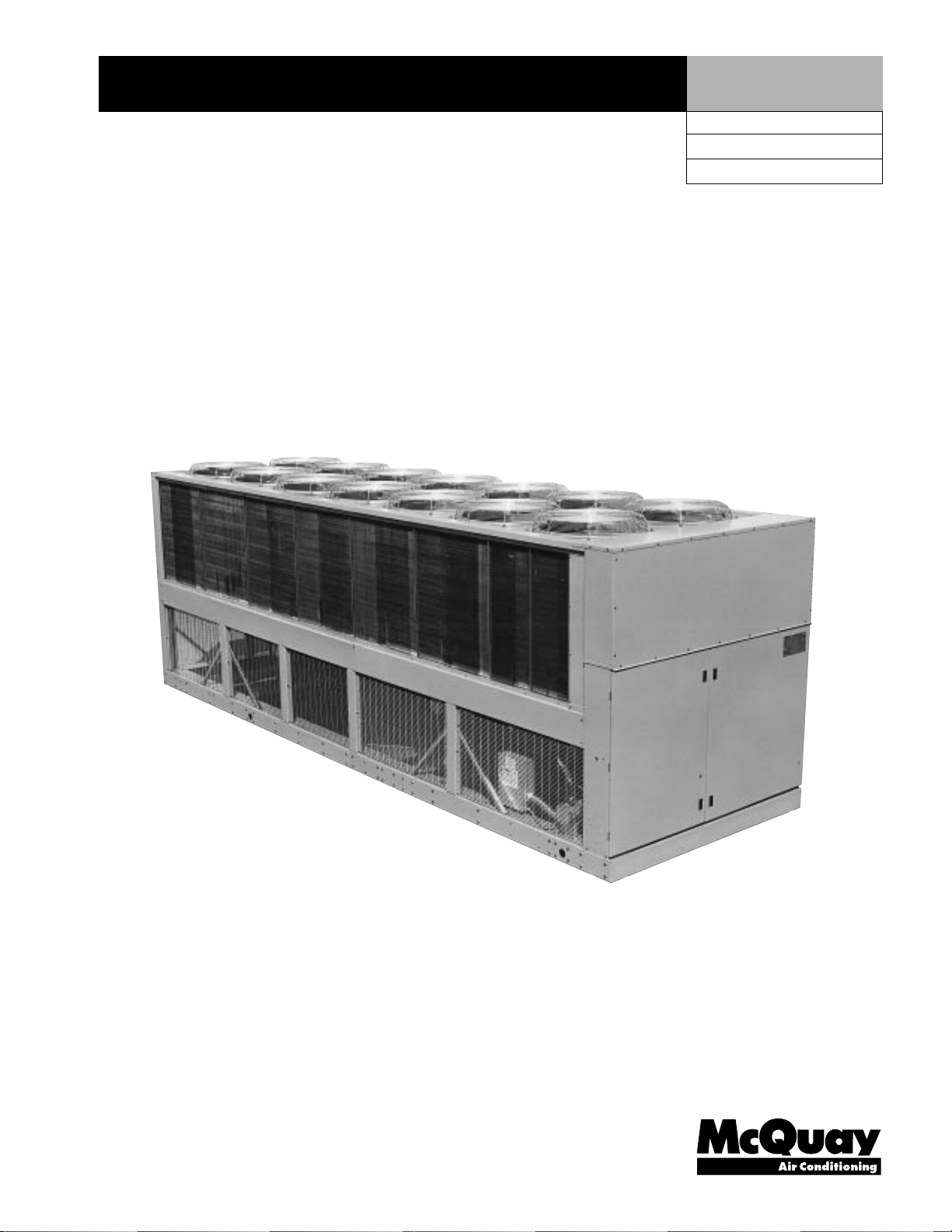
SeasonPak
®
Packaged Air Cooled Water Chiller
with Screw Compressor
Models ALS-125A thru 380A
©1996 McQuay International
®
Page 2

Table of Contents
Introduction ....................................................................... 3
General Description ....................................................... 3
Nomenclature ................................................................. 3
Inspection ...................................................................... 3
Installation and Start-up ............................................... 3-17
Handling ..................................................................... 3-6
Location ......................................................................... 6
Service Access .............................................................. 6-9
Vibration Isolators .................................................. 10-12
Water Piping ........................................................... 13-14
Flow Switch .................................................................. 14
Water Connections ....................................................... 15
Refrigerant Charge ....................................................... 15
Glycol Solutions ...................................................... 15-16
Evaporator Water Flow and Pressure Drop ............. 16-17
Physical Data .............................................................. 17-20
Major Components .......................................................... 21
Compressor Staging Sequence .................................... 21-23
Dimensional Data ...................................................... 24-27
Field Wiring ................................................................ 28-46
General ......................................................................... 28
Overload Dial Setting ................................................... 29
Wire Sizing Ampacities............................................30-35
Compressor and Condenser Fan Motors ................. 35-38
Customer Wiring.....................................................39-43
Electrical Data Notes .................................................... 44
Electrical Legend .......................................................... 45
Evaporator Freeze Protection ........................................ 45
Typical Field Wiring .................................................... 46
Unit Layout and Principles of Operation ................... 47-51
Major Component Locations ....................................... 47
Control Center ........................................................ 48-49
Sequence of Operation ............................................ 50-51
Refrigerant Piping Schematic ....................................... 51
Start-up and Shutdown ............................................... 52-54
Pre Start-up .................................................................. 52
Start-up ................................................................... 52-53
Temporary Shutdown................................................... 53
Start-up After Temporary Shutdown ...................... 53-54
Extended Shutdown ..................................................... 54
System Maintenance ................................................... 54-55
General ......................................................................... 54
Compressor Maintenance ............................................. 54
Fan Motor Bearings ...................................................... 54
Electrical Terminals ...................................................... 54
Condensers ................................................................... 55
Refrigerant Sightglass.................................................... 55
Lead-Lag ....................................................................... 55
Service ......................................................................... 55-61
Compressor Solenoids .................................................. 56
Filter-Driers ............................................................. 56-57
Liquid Line Solenoid Valve .......................................... 57
Liquid Injection Solenoid Valve ................................... 57
Electronic Expansion Valve .......................................... 58
Electronic Expansion Valve Operation ......................... 59
Evaporator .................................................................... 59
Refrigerant Charging ............................................... 59-61
In Warranty Return Material Procedure ......................... 61
Compressor .................................................................. 61
Components Other Than Compressors ........................ 61
Appendix ..................................................................... 61-77
Standard Controls: .................................................. 61-62
Thermistor sensors ..................................................... 61
Sensor locations .................................................... 62-65
Liquid presence sensor ................................................ 65
High condenser pressure control .................................. 65
Mechanical high pressure safety control ..................65-66
Compressor motor protection ...................................... 66
FanTrol head pressure control ............................... 66-68
Low ambient start ..................................................... 68
Phase/voltage monitor ................................................68
Compressor short cycling protection ............................. 69
Optional Controls: .................................................. 69-77
SpeedTrol head pressure control.................................. 69
Reduced inrush start .................................................. 69
Hot gas bypass ...................................................... 69-70
Wind baffles and hail guards ................................ 70-75
ALS controls, settings & functions .............................. 76
Troubleshooting chart ................................................ 77
Periodic Maintenance Log ............................................... 78
Limited Warranty ............................................................ 79
Page 2 / IM 548
IMPORTANT
See freeze protection references under the heading “Water Piping” on page 11.
“FanTrol”, “McQuay”, “SeasonPak”, “MicroTech” and “SpeedTrol” are registered trademarks of McQuay International, Minneapolis, MN.
©1996 McQuay International. All rights reserved throughout the world.
“Bulletin illustrations cover the general appearance of McQuay International products at the time of publication
and we reserve the right to make changes in design and construction at any time without notice.”
Page 3
Introduction
General Description
McQuay type SeasonPak® air cooled water chillers are complete, self-contained automatic refrigerating
units that include the latest in engineering components arranged to provide a compact and efficient
unit. Each unit is completely assembled, factory wired, evacuated, charged, tested and comes complete
and ready for installation. Each unit consists of multiple air cooled condensers with integral subcooler
sections, multiple accessible semi-hermetic single-screw compressors, replaceable tube multiple circuit
shell-and-tube evaporator, and complete refrigerant piping. Liquid line components included are
manual liquid line shutoff valves, charging valves, filter-driers, liquid line solenoid valves, sightglass/
moisture indicators, and electronic expansion valves. Other features include compressor heaters, an
evaporator heater for low ambient water freeze protection, automatic one time pumpdown of refrigerant
circuit upon circuit shutdown, and an advanced fully integrated microprocessor control system.
The electrical control center includes all safety and operating controls necessary for dependable automatic
operation, (the high and low pressure controls and the chiller heater thermostat are external from the electrical
control center.) Thermal overload protected condenser fan motors are fused in all three conductor legs
and started by their own three-pole contactors. Compressors are protected by solid state overload
protection and over temperature protection. Field installed fused disconnect offers additional
protection.
Nomenclature
A L S - 155 A
Air cooled Design vintage
Liquid refrigerant Nominal capacity (tons)
injected
Screw compressor
water chiller
Inspection
When the equipment is received, all items should be carefully checked against the bill of lading to insure
a complete shipment. All units should be carefully inspected for damage upon arrival. All shipping
damage must be reported to the carrier and a claim must be filed with the carrier. The unit’s serial plate
should be checked before unloading the unit to be sure that it agrees with the power supply available.
Physical damage to unit after acceptance is not the responsibility of McQuay International.
Note: Unit shipping and operating weights are available in the physical data tables.
Installation and Start-up
Note: Installation and maintenance are to be performed only by qualified personnel who are familiar
with local codes and regulations, and experienced with this type of equipment.
Sharp edges and coil surfaces are a potential injury
hazard. Avoid contact with them.
Start-up by McQuayService is included on all units sold for installation within the USA and Canada.
Two week prior notification of start-up is required. The contractor should obtain a copy of the Start-up
Scheduled Request Form from the sales representative or from the nearest office of McQuayService.
Handling
Care should be taken to avoid rough handling or shock due to impact or dropping the unit. Do not
push or pull the unit from anything other than the base, and block the pushing vehicle away from the
unit to prevent damage to the sheetmetal cabinet and end frame (see Figure 1).
Never allow any part of the unit to fall during unloading or moving as this may result in serious
damage.
IM 548 / Page 3
Page 4
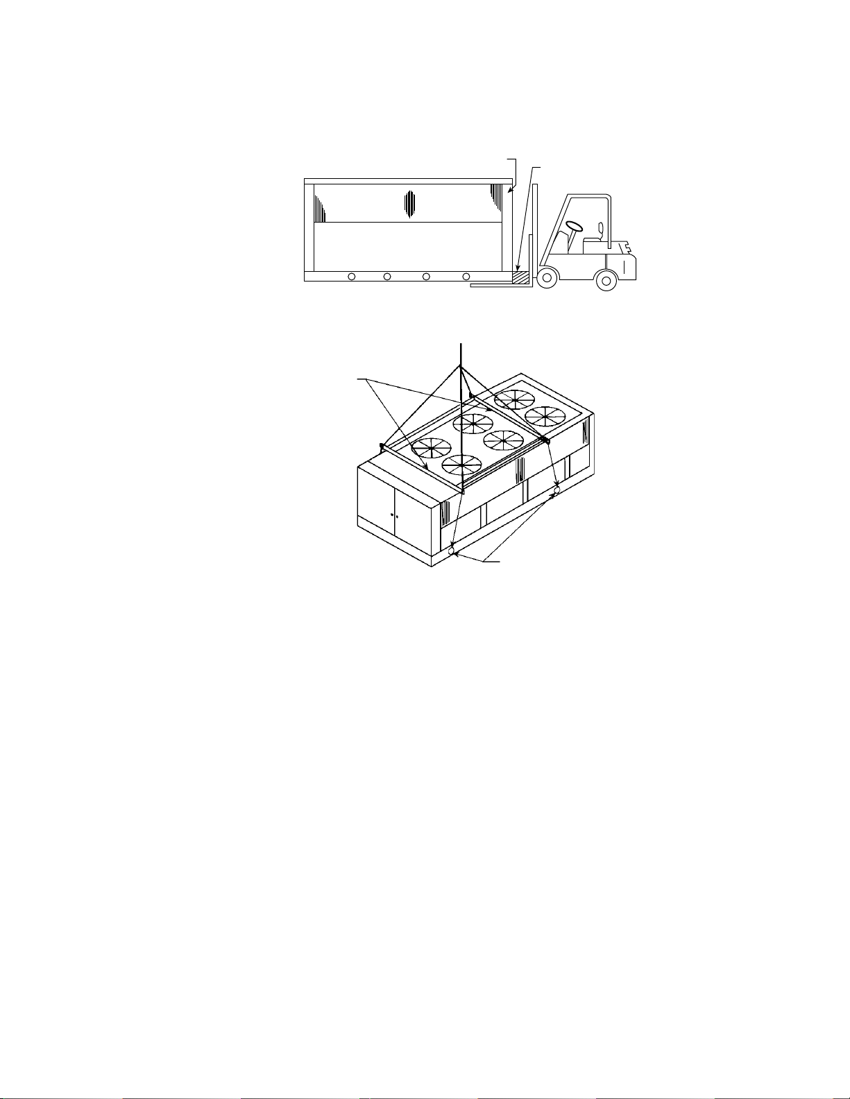
To lift the unit, 21/2" (64 mm) diameter lifting holes are provided in the base of the unit. Spreader bars
and cables should be arranged to prevent damage to the condenser coils or unit cabinet (see Figures 2, 3,
4 and 5).
Figure 1. Suggested pushing arrangement
Control panel end
Blocking required
across full width
Figure 2. Suggested lifting arrangement (125 thru 195)
Unit Models ALS125 thru 204
Speader bar
recommended
(Use caution)
Must use these rigging holes.
(Note control box location)
Lift only as shown
Note: Number of fans may vary from this diagram, but lifting method remains the same.
Page 4 / IM 548
Page 5
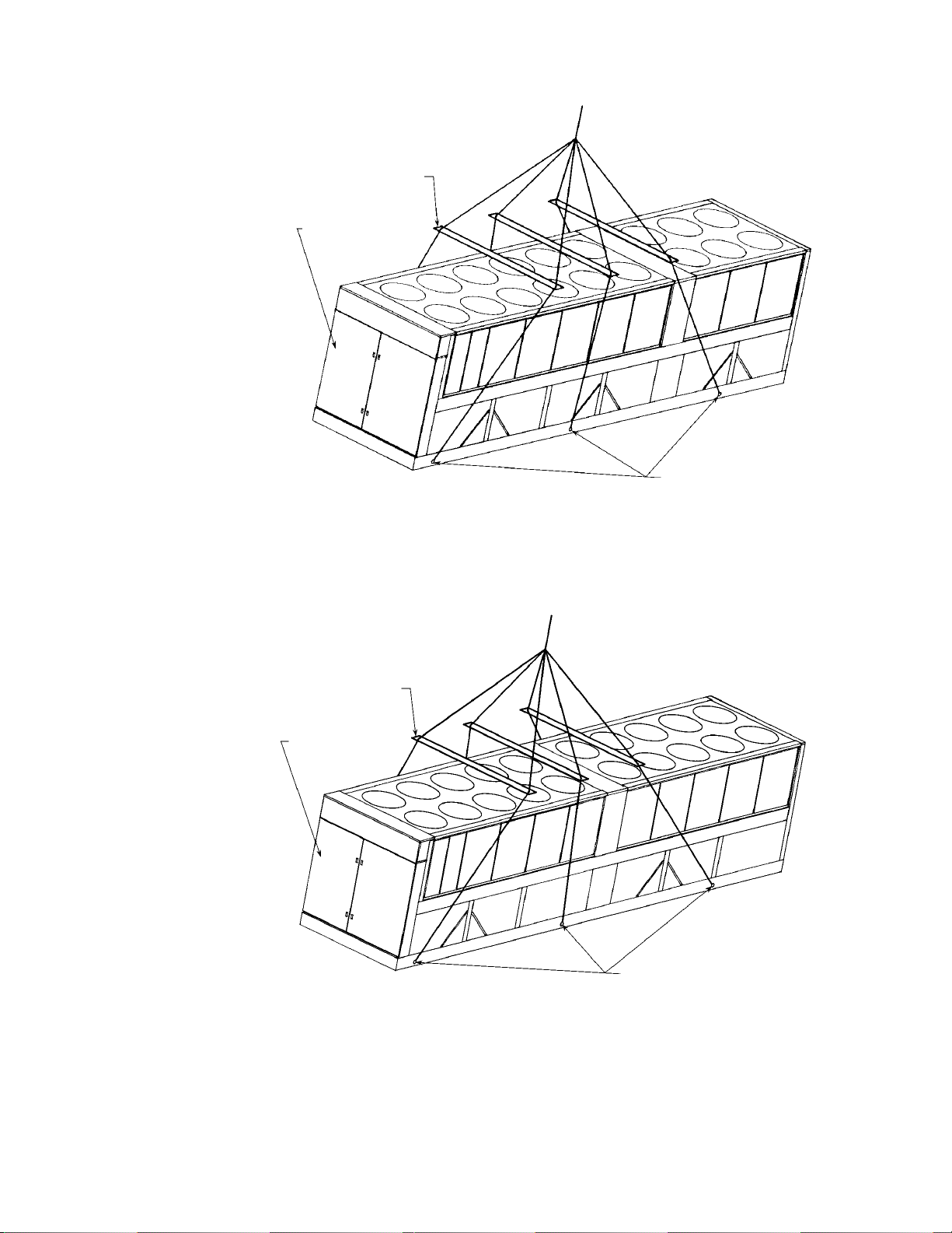
Figure 3. Suggested lifting arrangement (205 thru 280)
Spreader bars must be used
to prevent cabinet damage.
Locate bars above unit to
clear fan grilles. Minimum
distance across unit
between cables or chains
at bars is 90 inches.
Control box end
Unit Models ALS205 thru 280
Unit weights:
16,250 lbs. with aluminum fin coils
18,750 lbs. with copper fin coils
All (6) rigging holes must be used.
(Note control box locations)
Lift only from (6) base points as shown
Note: Number of fans may vary from this diagram, but lifting method remains the same.
Figure 4. Suggested lifting arrangement (300 thru 340)
Spreader bars must be used
to prevent cabinet damage.
Locate bars above unit to
clear fan grilles. Minimum
distance across unit
between cables or chains
at bars is 90 inches.
Control box end
Unit Models ALS300 thru 340
Unit weights:
20,400 lbs. with aluminum fin coils
24,075 lbs. with copper fin coils
All (6) rigging holes must be used.
(Note control box locations)
Lift only from (6) base points as shown
Note: Number of fans may vary from this diagram, but lifting method remains the same.
IM 548 / Page 5
Page 6
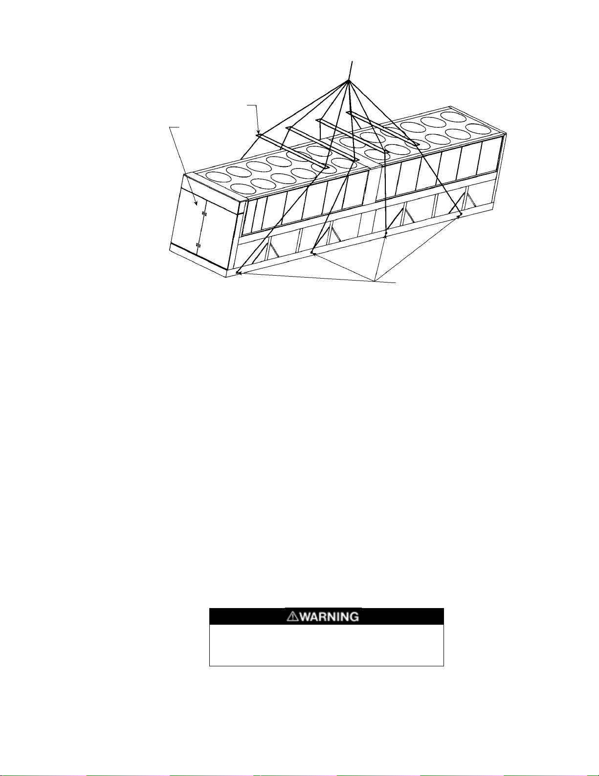
Figure 5. Suggested lifting arrangement (360 thru 380)
Spreader bars must be used
to prevent cabinet damage.
Locate bars above unit to
clear fan grilles. Minimum
distance across unit
between cables or chains
at bars is 90 inches.
Control box end
Note: Number of fans may vary from this diagram, but lifting method remains the same.
All (8) rigging holes must be used.
(Note control box locations)
Lift only from (8) base points as shown
Unit Models ALS360 thru 380
Unit weights:
22,100 lbs. with aluminum fin coils
22,506 lbs. with copper fin coils
Location
Care should be taken in the location of the unit to provide proper airflow to the condenser, minimizing
effects on condensing pressure.
Due to the vertical condenser design of the ALS125A thru ALS380A chillers, it is recommended that
the unit is oriented so that prevailing winds blow parallel to the unit length, thus minimizing the effects
of condensing pressure on performance. If the unit is installed with no protection against prevailing winds
it is recommended that wind baffles be installed.
Using less clearances than shown in Figures 6, 7 and 8 will cause discharge air recirculation to the
condenser and could have a significant and detrimental effect on unit performance.
Service Access
Each end of the unit must be accessible after installation for periodic service work. Compressors, filterdriers, and manual liquid line shutoff valves are accessible on each side of the unit adjacent to the
control box. High pressure and low pressure transducers are mounted on the compressor. The cooler
barrel heater thermostat is located on the cooler. Compressor overloads, microprocessor, and most other
operational, safety and starting controls are located in the unit control box.
On all ALS units the condenser fans and motors can be removed from the top of the unit. The complete
fan/motor assembly can be removed for service. The fan blade and fan motor rain shield must be
removed for access to wiring terminals at the top of the motor.
Disconnect all power to the unit while servicing
condenser fan motors. Failure to do so may cause
bodily injury or death.
Page 6 / IM 548
Page 7
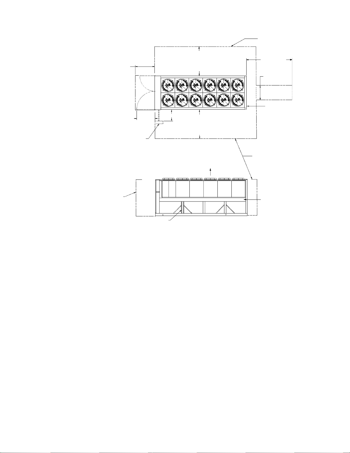
Figure 6. Clearance requirements (125 thru 204)
5'-0" if open fence
4'-0" working
clearance per
National Electric
Code Article
110-16
Field installed
disconnect switch,
locate so as not to
block service access
to unit components
3'-9"
door
swing
2'-0" min.
or 50% open wall
6'-0" if solid wall
(see note 3 for pit)
5'-0" if open fence
or 50% open wall
6'-0" if solid wall
(see note 3 for pit)
No obstructions allowed
above unit at any height
Top View
Air flow.
No obstructions.
Recommended area required
for unit operation, air flow
and maintenance
10'-0" clearance for
evaporator
service or removal
3'-0" gate
or opening
centered on
unit width
2'-0" min.
See notes 2 & 4
concerning wall height
Wall
or fence
See note 5
Elevation
See note 6
Notes:
1. Minimum side clearance between two units is 12 feet.
2. Unit must not be installed in a pit or enclosure that is deeper or taller than the height of the unit
unless extra clearance is provided per note 4.
3. Minimum clearance on each side is a 8 feet when installed in a pit no deeper than unit height.
4. Minimum side clearance to solid wall or building taller than unit height is 8 feet provided no solid
wall above 6 feet tall is closer than 12 feet to opposite side of unit.
5. Removable post for compressor service access must not be blocked at either side of unit.
6. Do not mount electrical conduits, etc. above the side rail on either side of unit.
7. There must be no obstruction of the fan discharge.
IM 548 / Page 7
Page 8
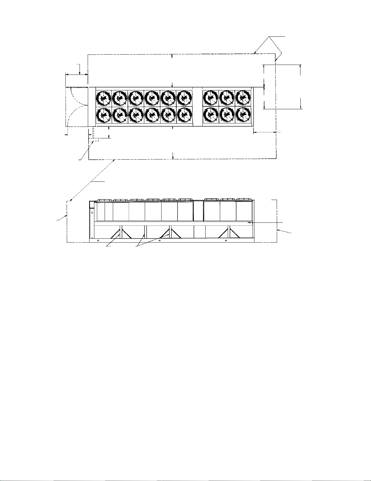
Figure 7. Clearance requirements (205 thru 280)
4'-0" working
clearance per
National Electric
Code Article 110-16
Control
Center
5'-0" if open fence
or 50% open wall
6'-0" if solid wall
(see note 3 for pit)
No obstructions.
Recommended area
required for unit
operation, air flow
and maintenance
access
8'-0" gate or access
opening centered on
corner of unit for
evaporator removal
3'-9"
door
swing
Field installed
disconnect switch,
locate so as not to
block service access to
unit components
Wall
or fence
2'-0" min.
See notes 2 & 4
concerning wall
height at unit sides
See note 5
5'-0" if open fence
or 50% open wall
6'-0" if solid wall
(see note 3 for pit)
Top View
Air Flow.
No obstructions allowed
above unit at any height
d
Side View
2'-0" min. for unit
operation.
4'-0" min. for major
component removal.
10'-0" min. for evaporator
removal (see access
opening dimension above)
See note 6
Wall or
fence
Notes:
1. Minimum side clearance between two units is 12 feet.
2. Unit must not be installed in a pit or enclosure that is deeper or taller than the height of the unit
unless extra clearance is provided per note 4.
3. Minimum clearance on each side is a 8 feet when installed in a pit no deeper than unit height.
4. Minimum side clearance to solid wall or building taller than unit height is 8 feet provided no solid
wall above 6 feet tall is closer than 12 feet to opposite side of unit.
5. Removable post for compressor service access must not be blocked at either side of unit.
6. Do not mount electrical conduits, etc. above the side rail on either side of unit.
7. There must be no obstruction of the fan discharge.
Page 8 / IM 548
Page 9
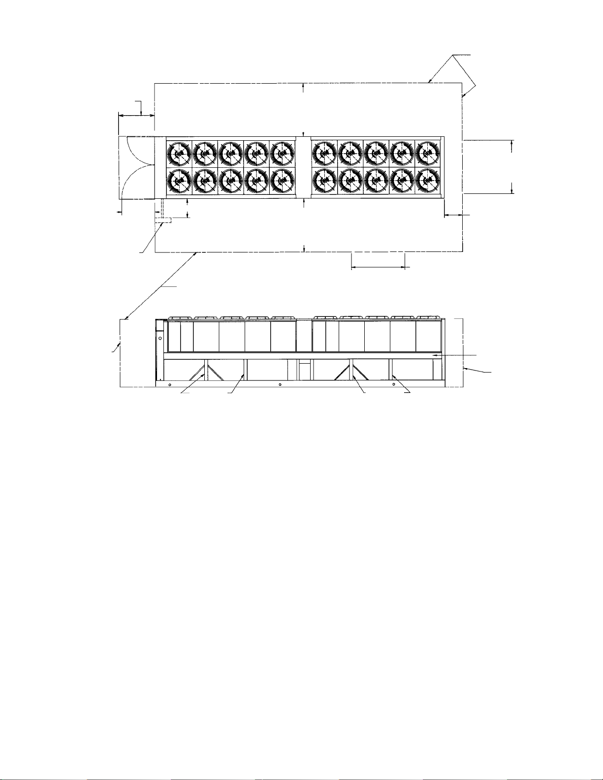
Figure 8. Clearance requirements (300 thru 380)
4'-0" working
clearance per
National Electric
Code Article 110-16
Control Center
3'-9"
door
swing
Field installed
disconnect switch, locate so
as not to block service access
to unit components
2'-0" min.
See notes 2 & 4
concerning wall
height at unit sides
5'-0" if open fence
or 50% open wall
6'-0" if solid wall
(see note 3 for pit)
5'-0" if open fence
or 50% open wall
6'-0" if solid wall
(see note 3 for pit)
Top View
Air Flow.
No obstructions allowed
above unit at any height
d
Alternate access
opening at side
opposite water
connections
No obstructions.
Recommended area
required for unit
operation, air flow
and maintenance
access
6'-0" gate or access
opening centered on
corner of unit for
evaporator removal
2'-0" min. for unit
operation.
4'-0" min. for major
component removal.
10'-0" min. for evaporator
removal (see access
opening dimension above)
Wall
or fence
See note 6
Wall or
fence
See note 5
Side View
See note 5
Notes:
1. Minimum side clearance between two units must be 12 feet.
2. Unit must not be installed in a pit that is deeper or enclosure higher than the height of the unit
unless extra clearance is provided per notes 3 and 4.
3. Minimum clearance on each side is a 8 feet when installed in a pit no deeper than unit height.
4. Minimum side clearance to solid wall or building higher than unit height is 8 feet. In addition, the
opposite side of the unit must be at least 12 feet away from a solid wall higher than 6 feet.
5. The removable posts for compressor or evaporator service access must not be blocked at either side of
unit.
6. Do not mount electrical conduits, etc. above the side rail on either side of unit.
IM 548 / Page 9
Page 10
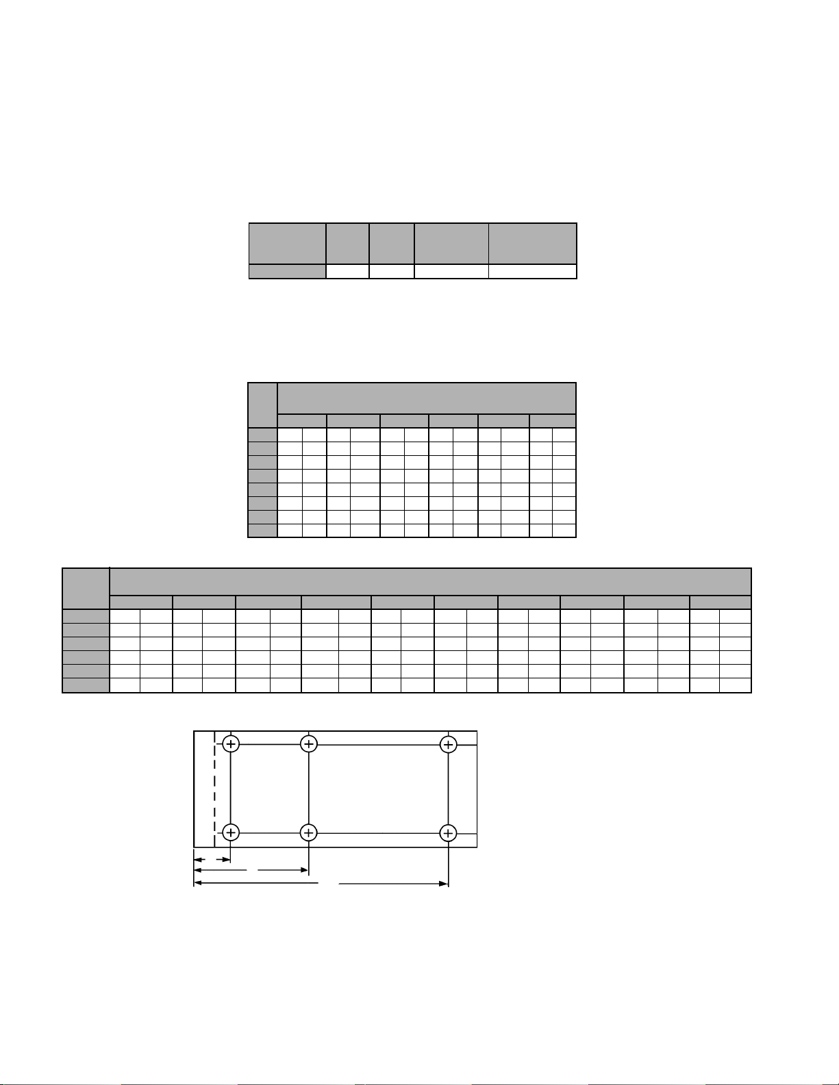
Vibration Isolators
Vibration isolators are recommended for all roof mounted installations or wherever vibration
transmission is a consideration. Figure 9 (125 thru 204), Figure 10 (205 thru 280), Figure 12 (300 thru
340) and Figure 13 (360 thru 380) show isolator locations in relation to the unit control center. Table 2
(125 thru 204), Table 3 (205 thru 280), Table 5 (300 thru 340) and Table 6 (360 thru 380) give the
isolator loads at each location shown in Figures 9, 10, 12 and 13. Figure 11 gives dimensions that are
required to secure each McQuay isolator section to the mounting surface.
Table 1. Vibration isolators (spring)
COLOR
ALS UNIT SIZE TYPE OF
125-280 CP2-32 White 0047792932 2600 (1180)
STRIPE
MCQUAY PART
NUMBER
RECOMMENDED
MAXIMUM LOAD
LBS. (KG)
Note: The same isolators are used when the chiller is
supplied with the optional copper finned condenser coils.
The spring is fully compressed at approximately 3900 lbs
(1769 kg).
Table 2. Isolator loads (125A thru 204A)
ALS
UNIT
SIZE
125A 1625 (737) 2065 (937) 1270 (576) 1625 (737) 2065 (937) 1270 (576)
140A 1680 (762) 2145 (973) 1350 (612) 1680 (762) 2145 (973) 1350 (612)
155A 1720 (780) 2205 (1000) 1410 (640) 1720 (780) 2205 (1000) 1410 (640)
170A 1730 (785) 2220 (1007) 1425 (647) 1730 (785) 2220 (1007) 1425 (647)
175A 1880 (853) 2350 (1066) 1395 (633) 1880 (853) 2350 (1066) 1395 (633)
185A 1880 (853) 2350 (1066) 1395 (633) 1880 (853) 2350 (1066) 1395 (633)
195A 1920 (871) 2440 (1107) 1440 (653) 1920 (871) 2440 (1107) 1440 (653)
204A 2081 (944) 2644 (1199) 1560 (707) 2081 (944) 2644 (1199) 1560 (707)
ISOLATOR LOADS AT EACH MOUNTING LOCATION
LBS (KG)
1 23456
Table 3. Isolator loads (205 thru 280)
ALS
UNIT
SIZE
205A 1790 (812) 1840 (834) 2040 (925) 1370 (621) 950 (431) 1630 (739) 2020 (916) 1640 (744) 1650 (748) 1000 (454)
220A 1790 (812) 1850 (839) 2050 (930) 1370 (621) 950 (431) 1630 (739) 2030 (921) 1650 (748) 1660 (753) 1000 (454)
235A 1820 (825) 1880 (853) 2080 (943) 1370 (621) 960 (435) 1670 (757) 2060 (934) 1680 (762) 1660 (753) 1000 (454)
250A 1820 (825) 1880 (853) 2080 (943) 1380 (626) 960 (435) 1670 (757) 2060 (934) 1680 (762) 1670 (757) 1000 (454)
265A 1820 (825) 1880 (853) 2080 (943) 1380 (626) 960 (435) 1670 (757) 2060 (934) 1680 (762) 1670 (757) 1000 (454)
280A 1830 (830) 1890 (857) 2080 (943) 1380 (626) 960 (435) 1680 (762) 2070 (939) 1690 (766) 1670 (757) 1000 (454)
12345678910
ISOLATOR LOADS AT EACH MOUNTING LOCATION
LBS (KG)
Page 10 / IM 548
Figure 9. Isolator locations (125A thru 204A)
4
Control Center
1
A
B
5
2
C
6
A = 13" (330 mm)
B = 95" (2413 mm)
C = 215" (5461 mm) ALS125A-155A
250" (6350 mm) ALS170A-204A
3
Page 11
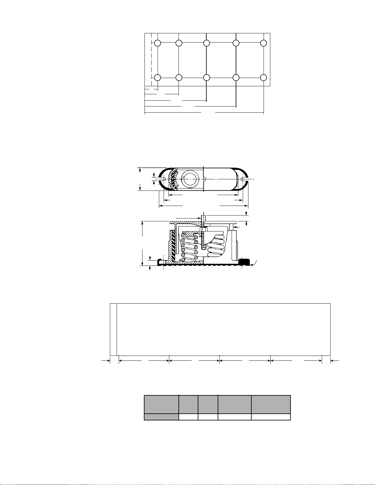
Figure 10. Isolator locations (205 thru 280)
67 8 9 10
12 3 4 5
Control Center
A
▼
▼
B
▼
▼▼▼
A = 13" (330 mm)
B = 95" (2413 mm)
C = 177" (4496 mm)
D = 259" (6579 mm)
E = 341" (8661 mm)
Figure 11. Spring flex isolator
3"
(76.2 mm)
3
⁄8"(15.8mm)
1
⁄2" (12.7 mm) dia.
positioning pin
6" free ht.
(152.4 mm)
9
⁄16" (14.1 mm)
++
++
▼
C
D
+ + +
+++
▼
E
73⁄4" (196.8 mm)
91⁄4" (234.9 mm) C-C FDTN. bolt
1
⁄2" (266.70 mm)
10
9
⁄16"(14.1mm)
▼
▼
5
⁄8" (15.8 mm)
Adjust mounting so that
upper housing clears
lower housing by at least
1
⁄4" (6.3 mm) and not
more than
1
⁄2" (12.7 mm)
1
⁄4" (6.3 mm)
acoustical non-skid
neoprene pad
Figure 12. Vibration isolator (300 thru 340)
•
1
Control Center
2
•
82 82 82
•
3
4
•
Table 4. Vibration isolators (spring)
ALS UNIT SIZE TYPE OF
300A-340A CP2-32 White 047792932 3000 (1360)
Note:
The same isolators are used when the chiller is supplied with the optional
copper finned condenser coils. The spring is fully compressed at
approximately 3900 lbs (1769 kgs).
COLOR
STRIPE
•
5
6
•
MCQUAY PART
NUMBER
•
7
8
•
RECOMMENDED
MAXIMUM LOAD
LBS (KG)
116.7
•
9
10
•
1413
IM 548 / Page 11
Page 12
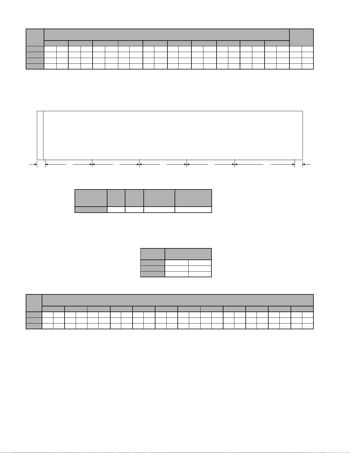
Table 5. Operating weight loads (300 thru 340)
ALS
UNIT WEIGHT
SIZE
300A
315A
330A
340A
Note: 1. Unit to be supported at (5) isolator mounting locations per side, 10 total, as indicated.
2. Add approximately 370 lbs (168 kgs) at each isolator location for units with optional copper finned condenser coils.
3. Unit to be level in both directions within 1⁄8 inch (3 mm) per 10 feet (3 m).
4. See dimensional drawing 073124701 for exact location of isolator support holes in base frame.
OPERATING WEIGHT LOAD AT ISOLATOR LOCATIONS, LBS (KGS) FOR UNITS WITH ALUMINUM FINNED COILS
12345 678910
1780 (807) 2060 (934) 2530 (1147) 2530 (1147) 2560 (1161) 2560 (1161) 2170 (984) 2170 (984) 1445 (655) 1445 (655) 21250 (9637)
1780 (807) 2060 (934) 2530 (1147) 2530 (1147) 2560 (1161) 2560 (1161) 2170 (984) 2170 (984) 1445 (655) 1445 (655) 21250 (9637)
1780 (807) 2060 (934) 2540 (1152) 2540 (1152) 2570 (1166) 2570 (1166) 2180 (989) 2180 (989) 1450 (658) 1450 (658) 21320 (9669)
1780 (807) 2060 (934) 2540 (1152) 2540 (1152) 2570 (1166) 2570 (1166) 2180 (989) 2180 (989) 1450 (658) 1450 (658) 21320 (9669)
OPERATING
LBS (KGS)
Figure 13. Vibration isolator (360 thru 380)
•
1
Control Center
2
•
13
•
3
4
•
•
5
6
•
•
7
8
•
•
9
10
•
10482 82 82 82
•
11
12
•
14
Table 6. Vibration isolators (spring)
ALS UNIT SIZE TYPE OF
COLOR
STRIPE
360A-380A CP2-32 White 047792932 3000 (1360)
MCQUAY PART
NUMBER
RECOMMENDED
MAXIMUM LOAD
LBS (KG)
Note: The same isolators are used
when the chiller is supplied with the
optional copper finned condenser
coils. The spring is fully compressed
at approximately 3900 lbs (1769 kgs).
Table 7. Weights (360 thru 380)
ALS OPERATING WEIGHT
UNIT SIZE LBS (KGS)
360A 22920 (10394)
370A 22970 (10417)
380A 23020 (10440)
Table 8. Operating weight loads (360 thru 380)
ALS
UNIT
SIZE
360A
1780 (807) 2060 (934) 2530 (1147) 2530 (1147) 2540 (1152) 2540 (1152) 1670 (757) 1670 (757) 1720 (780) 1720 (780) 1080 (490) 1080 (490)
370A
1780 (807) 2060 (934) 2540 (1152) 2540 (1152) 2550 (1156) 2550 (1156) 1675 (760) 1675 (760) 1720 (780) 1720 (780) 1080 (490) 1080 (490)
380A
1780 (807) 2060 (934) 2550 (1156) 2550 (1156) 2560 (1161) 2560 (1161) 1680 (762) 1680 (762) 1720 (780) 1720 (780) 1080 (490) 1080 (490)
Note: 1. Unit to be supported at (6) isolator mounting locations per side, 12 total, as indicated.
2. Add approximately 370 lbs (168 kgs) at each isolator location for units with optional copper finned condenser coils.
3. Unit to be level in both directions within 1⁄8 inch (3 mm) per 10 feet (3 m).
4. See dimensional drawing 073124801 for exact location of isolator support holes in base frame.
OPERATING WEIGHT LOAD AT ISOLATOR LOCATIONS, LBS (KGS) FOR UNITS WITH ALUMINUM FINNED COILS
123 456 78 9101112
Page 12 / IM 548
Page 13
Water Piping
Due to the variety of piping practices, it is advisable to follow the recommendations of local authorities.
They can supply the installer with the proper building and safety codes required for a safe and proper
installation.
Basically, the piping should be designed with a minimum number of bends and changes in elevation to
keep system cost down and performance up. It should contain:
1. Vibration eliminators to reduce vibration and noise transmission to the building.
2. Shutoff valves to isolate the unit from the piping system during unit servicing.
3. Manual or automatic air vent valves at the high points of the system. Drains at the low parts in the
system.
4. Some means of maintaining adequate system water pressure (e.g., expansion tank or regulating valve).
5. Temperature and pressure indicators located at the unit to aid in unit servicing.
6. A strainer or some means of removing foreign matter from the water before it enters the pump. It
should be placed far enough upstream to prevent cavitation at the pump inlet (consult pump
manufacturer for recommendations). The use of a strainer will prolong pump life and thus keep
system performance up.
7. A strainer should also be placed in the supply water line just prior to the inlet of the evaporator.
This will aid in preventing foreign material from entering and decreasing the performance of the
evaporator.
8. The shell-and-tube cooler has a thermostat and heating cable to prevent freeze-up, due to low
ambient, down to -20°F (-28.8°C). It is suggested that the heating cable be wired to a separate 110V
supply circuit. As shipped from the factory, it is factory wired to the control circuit. Any water
piping to the unit must also be protected to prevent freezing.
9. If the unit is used as a replacement chiller on a previously existing piping system, the system should
be thoroughly flushed prior to unit installation and then regular chilled water analysis and chemical
water treatment is recommended immediately at equipment start-up.
10. The total water quantity in the system should be sufficient to prevent frequent “on-off” cycling. A
reasonable minimum quantity would allow for a complete water system turnover in not less than 15
minutes.
11. In the event glycol is added to the water system, as an afterthought for freeze protection, recognize
that the refrigerant suction pressure will be lower, cooling performance less, and water side pressure
drop greater. If the percentage of glycol is large, or if propylene is employed in lieu of ethylene
glycol, the added pressure drop and loss of performance could be substantial.
12. For operations requiring the ice mode feature, logic in MicroTech will adjust the freezestat to a
pressure equivalent to 13.5°F (7.5°C) below the leaving evaporator water temperature. However, if a
different freezestat pressure value is desired, the freezestat can be manually changed through
MicroTech. Refer to IM549 for additional information.
If a separate disconnect is used for the 110V supply
to the cooler heating cable, it should be clearly
marked so that it is not accidentally shut off during
cold seasons.
Prior to insulating the piping and filling the system, a preliminary leak check should be made.
Piping insulation should include a vapor barrier to prevent moisture condensation and possible damage
to the building structure. It is important to have the vapor barrier on the outside of the insulation to
prevent condensation within the insulation on the cold surface of the pipe.
IM 548 / Page 13
Page 14
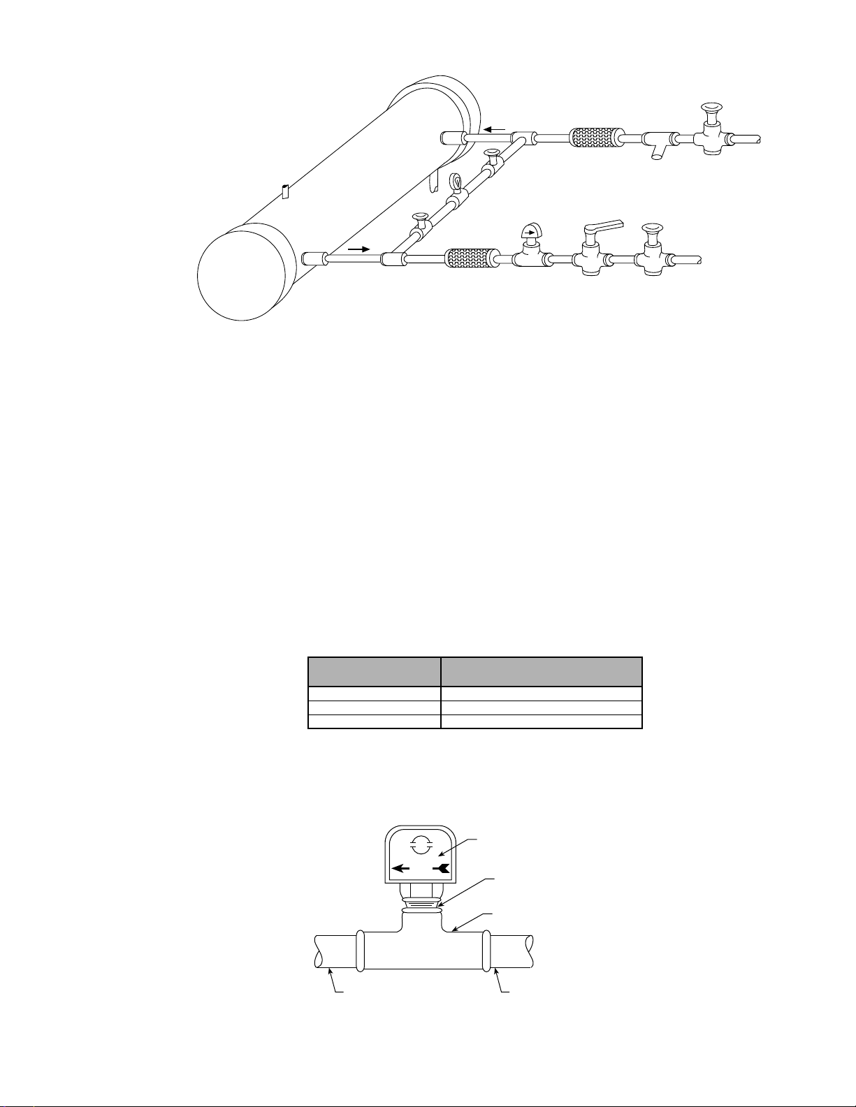
Figure 14. Typical field water piping
Inlet
Refrigerant
Connections
this end
Vent
Outlet
Drain
Valved
Pressure
Gauge
Vibration
Eliminator
Flow
Switch
Vibration
Eliminator
Balancing
Valve
Water
Strainer
Gate
Valve
Gate
Valve
Flow Switch
A water flow switch must be mounted in either the entering or leaving water line to insure that there
will be adequate water flow to the evaporator before the unit can start. This will safeguard against
slugging the compressors on start-up. It also serves to shut down the unit in the event that water flow is
interrupted to guard against evaporator freeze-up.
A flow switch is available from McQuay under ordering number 0017503300. It is a “paddle” type switch
and adaptable to any pipe size from 1" (25mm) to 8" (203mm) nominal. Certain minimum flow rates are
required to close the switch and are listed in Table 9. Installation should be as shown in Figure 15.
Electrical connections in the unit control center should be made at terminals 62 and 63. The normally
open contacts of the flow switch should be wired between these two terminals. Flow switch contact quality
must be suitable for 24 VAC, low current (16ma). Flow switch wire must be in separate conduit from
any high voltage conductors (115 VAC and higher).
Table 9. Flow switch minimum flow rates
Page 14 / IM 548
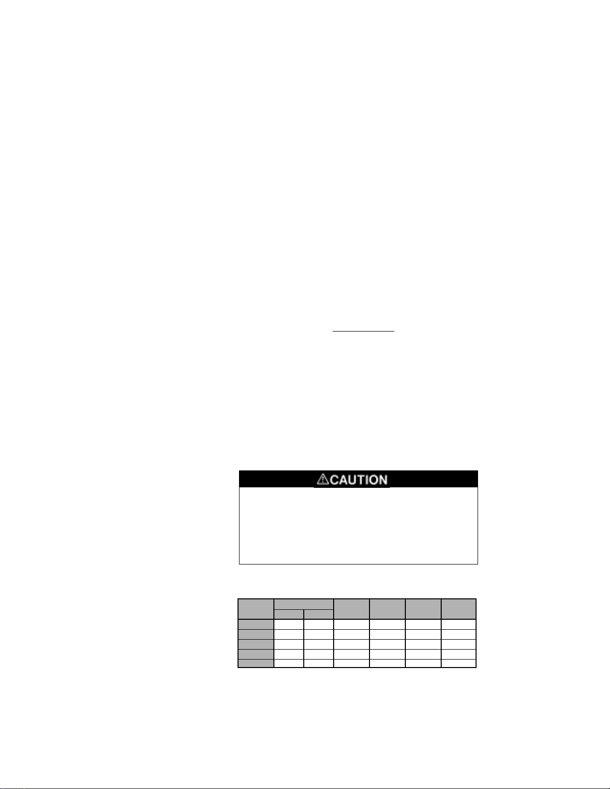
Figure 15. Flow switch
NOMINAL PIPE SIZE MINIMUM REQUIRED FLOW TO
INCHES (MM) ACTIVATE SWITCH - GPM (LPS)
5 (127) 58.7 (3.7)
6 (152) 79.2 (5.0)
8 (203) 140 (8.8)
Note: Water pressure differential switches are not recommended for
outdoor applications.
Flow direction
marked on switch
Flow
5" pipe dia.–
minimum after switch
1.00" NPT flow
switch connection
Te e
5" pipe dia.–
minimum before switch
Page 15
Water Connections
Water piping to the cooler can be brought up through the bottom of the unit or through the side
between the vertical supports. The dimensional data on pages 20-23 gives the necessary dimensions and
locations for all piping connections.
Note: On unit size 175A thru 204A there is a diagonal brace off of a vertical support which will
interfere with the water connection if brought in from the side. This brace can be removed, but only
after the unit is in place.
Refrigerant Charge
All units are designed for use with HCFC-22 and are compatible with HCFC alternatives and are
shipped with a full operating charge. The operating charge for each unit is shown in the Physical Data
Tables on pages 17-20.
Glycol Solutions
The system glycol capacity, glycol solution flow rate, and pressure drop through the cooler may be
calculated using the following formulas and tables.
Note: The procedure below does not specify the type of glycol. Use the derate factors found in Table 10
for corrections when using Ethylene glycol and those in Table 11 for Propylene glycol.
1. Capacity — Cooling capacity is reduced from that with plain water. To find the reduced value
multiply the chiller’s water system tonnage by the capacity correction factor to find the chiller’s
capacity in the glycol system.
2. Flow — To determine flow (or delta-T) knowing delta-T
(or flow) and cap:
Glycol flow = 24 x cap (glycol) x flow factor
delta-T
3. Pressure drop — To determine pressure drop through the cooler, when using glycol, enter the water
pressure drop graph on page 13 at the actual glycol flow. Multiply the water pressure drop found
there by the PD factor to obtain corrected glycol pressure drop.
4. To determine glycol system kW, multiply the water system kW by factor called Power.
Test coolant with a clean, accurate glycol solution hydrometer (similar to that found in service stations)
to determine the freezing point. Obtain percent glycol from the freezing point table below. On
glycol applications it is normally recommended by the supplier that a minimum of 25% solution by
weight be used for protection against corrosion.
Do not use an automotive grade antifreeze. Industrial
grade glycols must be used. Automotive antifreeze
contains inhibitors which will cause plating on the
copper tubes within the chiller evaporator. The type
and handling of glycol used must be consistent with
local codes.
Table 10. Ethylene glycol
%
P.G.
10 26 -3 0.991 0.996 1.013 1.070
20 18 -8 0.982 0.992 1.040 1.129
30 7 -14 0.972 0.986 1.074 1.181
40 –7 -22 0.961 0.976 1.121 1.263
50 –28 -33 0.946 0.966 1.178 1.308
FREEZE PT.
°F °C
CAP POWER FLOW PD
IM 548 / Page 15
Page 16
Table 11. Propylene glycol
%
P.G.
10 26 -3 0.987 0.992 1.010 1.068
20 19 -7 0.975 0.985 1.028 1.147
30 9 -13 0.962 0.978 1.050 1.248
40 –5 -21 0.946 0.971 1.078 1.366
50 –27 -33 0.929 0.965 1.116 1.481
FREEZE PT.
°F °C
CAP POWER FLOW PD
Evaporator Water Flow and Pressure Drop
Balance the chilled water flow through the evaporator. The flow rates must fall between the minimum and
maximum values shown in Table 12. Flow rates below the minimum values shown will result in laminar
flow which will reduce efficiency, cause erratic operation of the electronic expansion valve and could
cause low temperature cutouts. On the other hand flow rates exceeding the maximum values shown can
cause erosion on the evaporator water connections and tubes.
Measure the chilled water pressure drop through the evaporator at field installed pressure taps. It is
important not to include valves or strainers in these readings.
Variable chilled water flow through the evaporator while the compressor(s) are operating is not
recommended. MicroTech control set points are based upon a constant flow and variable temperature.
Table 12. Min/max evaporator flow rates
ALS UNIT
SIZE
125 186 11.8 497 31.4
140 209 13.2 557 35.2
155 231 14.6 617 39.0
170 253 16.0 675 42.7
175 256 16.2 683 43.2
185 274 17.3 730 46.1
195 284 18.0 767 48.5
204 303 19.1 808 51.0
205 309 19.5 825 52.1
220 335 21.2 893 56.4
235 356 22.5 950 60.0
250 376 23.8 1000 63.2
265 391 24.7 1043 66.0
280 408 25.8 1088 68.8
300 440 27.8 1173 74.1
315 459 29.0 1222 77.1
330 479 30.2 1276 80.6
340 493 31.1 1313 82.9
360 523 33.0 1395 88.1
370 540 34.1 1438 90.8
380 559 35.3 1490 94.1
MIN. FLOW RATE MAX. FLOW RATE
GPM LPS GPM LPS
Page 16 / IM 548
Page 17
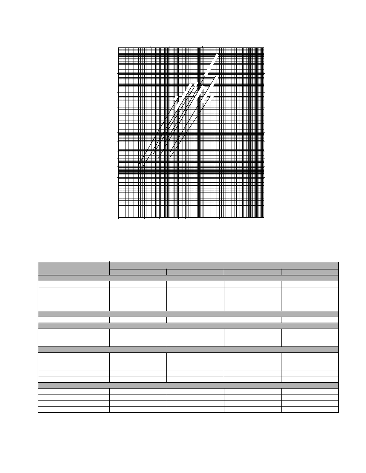
Figure 16. Evaporator water pressure drop
50
40
30
25
20
O)
2
15
10
9
8
7
6
Pressure Drop (ft. of H
5
4
3
10 15 20 25 30 40 50 60 90
Flow (LPS)
195
125
140, 155, 170, 175, 185
205, 220, 235
204, 250, 265, 280
330, 340, 360, 370, 380
300, 315
150
120
90
75
60
45
30
27
24
21
18
15
12
9
Pressure Drop (kPa)
100 200 300 400
600 800 1000 1500
500
Flow (GPM)
Physical Data
Table 13. Unit sizes 70 thru 100
DATA
070A 080A 090A 100A
BASIC DATA
Unit Capacity @ ARI Conditions, tons 68.7 81.9 93.2 98.7
Unit Operating Charge R-22, lbs. 150 160 180 190
Cabinet Dimensions, L x W x H, in. 124.5 x 83.4 x 93.3 124.5 x 83.4 x 93.3 159.1 x 83.4 x 93.3 159.1 x 83.4 x 93.3
Unit Operating Weight, lbs. 5725 6175 6825 7300
Unit Shipping Weight, lbs. 5500 5900 6500 6900
COMPRESSORS, SCREW, SEMI-HERMETIC
Nominal Capacity, tons 65 80 95 95
CONDENSERS, HIGH EFFICIENCY FIN & TUBE TYPE WITH INTEGRAL SUBCOOLER
Coil Face Area, ft.
2
115.6 115.6 154.1 154.1
Finned Height x Finned Length, in. 160 x 104 161 x 104 160 x 138.7 160 x 138.7
Fins Per Inch x Rows Deep 16 x 3 16 x 3 16 x 3 16 x 3
CONDENSER FANS, DIRECT DRIVE PROPELLER TYPE
No. of Fans — Fan Diameter, in. 6 - 28 6 - 28 8 - 28 8 - 28
No. of Motors — hp 6 - 1.5 6 - 1.5 8 - 1.5 8 - 1.5
Fan & Motor RPM 1140 1140 1140 1140
Fan Tip Speed, fpm 8357 8357 8357 8357
Total Unit Airflow, ft3/sec 54120 54120 72160 72160
EVAPORATOR, DIRECT EXPANSION, BAFFLED SHELL & THRU TUBE
Shell Diameter — Tube Length (in. - ft.) 12 - 08 14 - 08 14 - 10 16 - 10
Water Volume, gallons 24.3 32.6 41.3 43.6
Max. Water Pressure, psi 175 175 175 175
Max. Refrigerant Pressure, psi 225 225 225 225
ALS MODEL NUMBER
IM 548 / Page 17
Page 18
Table 14. Unit sizes 125 thru 170
DATA 125A 140A 155A 170A
BASIC DATA
Unit capacity @ ARI conditions, tons (kW) 62.2 (218) 62.2 (218) 64.4 (226) 75 (263) 77.1 (271) 77.1 (271) 79 (278) 89.7 (315)
Unit operating charge R-22, lbs. (kg) 140 (63.5) 140 (63.5) 140 (63.5) 150 (68.1) 150 (68.1) 150 (68.1) 150 (68.1) 160 (72.6)
Cabinet dimensions L x W x H, in. (mm)
Unit operating weight, lbs. (kg) 9920 (4500) 10350 (4700) 10670 (4840) 10750 (4880)
Unit shipping weight, lbs. (kg) 9600 (4355) 9900 (4490) 10250 (4650) 10350 (4700)
COMPRESSORS, SCREW, SEMI-HERMETIC
Nominal tons, (kW) 65 (230) 65 (230) 65 (230) 80 (280) 80 (280) 80 (280) 80 (280) 95 (335)
CONDENSERS, HIGH EFFICIENCY FIN & TUBE TYPE WITH INTEGRAL SUBCOOLER
Coil face area, sq. ft. (m2) 115.6 (10.7) 115.6 (10.7) 115.6 (10.7) 115.6 (10.7) 115.6 (10.7) 115.6 (10.7) 115.6 (10.7) 115.6 (10.7)
Finned height x finned length, in. (mm)
Fins per inch x rows deep 16 x 3 16 x 3 16 x 3 16 x 3 16 x 3 16 x 3 16 x 3 16 x 3
CONDENSER FANS, DIRECT DRIVE PROPELLER TYPE
No. of fans – fan diameter, in. (mm) 10 – 28 (711) 10 – 28 (711) 12 – 28 (711) 12 – 28 (711)
No. of motors – hp (kW) 10 – 1.5 (1.1) 10 – 1.5 (1.1) 12 – 1.5 (1.1) 12 – 1.5 (1.1)
Fan & motor rpm, 60 1140 1140 1140 1140
60 Hz fan tip speed, fpm 8357 8357 8357 8357
60 Hz total unit airflow, cfm 90200 90200 108240 108240
EVAPORATOR, DIRECT EXPANSION, BAFFLED SHELL & THRU TUBE
Shell diameter – tube length 14 – 10 16 – 10 16 – 10 16 – 10
in. (mm) – ft. (mm) (356 – 3048) (406 – 3048) (406 – 3048) (406 – 3048)
Water volume, gallons (L) 36.1 (136.7) 45.6 (172.6) 43.6 (165.0) 43.6 (165.0)
Max. water pressure, psi (kPa) 175 (1207) 175 (1207) 175 (1207) 175 (1207)
Max. refrigerant pressure, psi (kPa) 225 (1552) 225 (1552) 225 (1552) 225 (1552)
CKT. 1 CKT. 2 CKT. 1 CKT. 2 CKT. 1 CKT. 2 CKT. 1 CKT. 2
228.7 x 83.4 x 92.5 228.7 x 83.4 x 92.5 228.7 x 83.4 x 92.5 228.7 x 83.4 x 92.5
(5809 x 2118 x 2350) (5809 x 2118 x 2350) (5809 x 2118 x 2350) (5809 x 2118 x 2350)
80 x 208 80 x 208 80 x 208 80 x 208 80 x 208 80 x 208 80 x 208 80 x 208
(2032 x 5283) (2032 x 5283) (2032 x 5283) (2032 x 5283) (2032 x 5283) (2032 x 5283) (2032 x 5283) (2032 x 5283)
ALS MODEL NUMBER
Table 15. Unit sizes 175 thru 204
DATA 175A 185A 195A 204A
BASIC DATA
Unit capacity @ ARI conditions, tons (kW) 80.4 (282) 90.6 (318) 91.2 (320) 91.2 (320) 94.6 (332) 94.6 (332) 101 (355) 101 (355)
Unit operating charge R-22, lbs. (kg) 160 (72.6) 160 (72.6) 160 (72.6) 160 (72.6) 170 (77.1) 170 (77.1) 195 (88.4) 195 (88.4)
Cabinet dimensions 263.4 x 83.4 x 92.5 263.4 x 83.4 x 92.5 263.4 x 83.4 x 92.5 263.4 x 83.4 x 92.5
L x W x H, in. (mm) (6690 x 2118 x 2350) (6690 x 2118 x 2350) (6690 x 2118 x 2350) (6690 x 2118 x 2350)
Unit operating weight, lbs. (kg) 11250 (5100) 11250 (5100) 11500 (5218) 12570 (5701)
Unit shipping weight, lbs. (kg) 10850 (4920) 10850 (4920) 11100 (5036) 11980 (5433)
COMPRESSORS, SCREW, SEMI-HERMETIC
Nominal tons, (kW) 80 (280) 95 (335) 95 (335) 95 (335) 95 (335) 95 (335) 95 (335) 95 (335)
CONDENSERS, HIGH EFFICIENCY FIN & TUBE TYPE WITH INTEGRAL SUBCOOLER
Coil face area, sq. ft. (m2) 135.0 (12.5) 135.0 (12.5) 135.0 (12.5) 135.0 (12.5) 135.0 (12.5) 135.0 (12.5) 135.0 (12.5) 135.0 (12.5)
Finned height x finned length, in. (mm)
Fins per inch x rows deep 16 x 3 16 x 3 16 x 3 16 x 3 16 x 3 16 x 3 12 x 4 12 x 4
CONDENSER FANS, DIRECT DRIVE PROPELLER TYPE
No. of fans – fan diameter, in. (mm) 14 – 28 (711) 14 – 28 (711) 14 – 28 (711) 14 – 28 (711)
No. of motors – hp (kW) 14 – 1.5 (1.1) 14 – 1.5 (1.1) 14 – 1.5 (1.1) 14 – 2.0 (1.5)
Fan & motor rpm, 60 1140 1140 1140 1140
60 Hz fan tip speed, fpm 8357 8357 8357 8357
60 Hz total unit airflow, cfm 126280 126280 126280 138908
EVAPORATOR, DIRECT EXPANSION, BAFFLED SHELL & THRU TUBE
Shell diameter – tube length 16 – 10 16 – 10 18 – 10 20 – 10
in. (mm) – ft. (mm) (406 –3048) (406 – 3048) (457 – 3048) (508 – 3048)
Water volume, gallons (L) 43.6 (165.0) 43.6 (165.0) 57.3 (216.9) 69.6 (263.5)
Max. water pressure, psi (kPa) 175 (1207) 175 (1207) 175 (1207) 175 (1207)
Max. refrigerant pressure, psi (kPa) 225 (1552) 225 (1552) 225 (1552) 225 (1552)
CKT. 1 CKT. 2 CKT. 1 CKT. 2 CKT. 1 CKT. 2 CKT. 1 CKT. 2
80 x 243 80 x 243 80 x 243 80 x 243 80 x 243 80 x 243 80 x 243 80 x 243
(2032 x 6172) (2032 x 6172) (2032 x 6172) (2032 x 6172) (2032 x 6172) (2032 x 6172) (2032 x 6172) (2032 x 6172)
ALS MODEL NUMBER
Page 18 / IM 548
Page 19
Table 16. Unit sizes 205 thru 235
DATA 205A 220A 235A
BASIC DATA
Unit capacity @ ARI conditions, tons (kW) 64.4 (226) 66.1 (232) 75.8 (266) 66.1 (232) 78.2 (275) 79.0 (277) 79.3 (279) 79.3 (279) 79.0 (277)
Unit operating charge R-22, lbs. (kg) 140 (63.5) 140 (63.5) 150 (68.1) 140 (63.5) 150 (68.1) 150 (68.1) 150 (68.1) 150 (68.1) 150 (68.1)
Cabinet dimensions 355 x 83.4 x 94.5 355 x 83.4 x 94.5 355 x 83.4 x 94.5
L x W x H, in. (mm) (9017 x 2118 x 2400) (9017 x 2118 x 2400) (9017 x 2118 x 2400)
Unit operating weight, lbs. (kg) 15930 (7224) 15980 (7247) 16180 (7338)
Unit shipping weight, lbs. (kg) 15250 (6916) 15330 (6952) 15530 (7043)
COMPRESSORS, SCREW, SEMI-HERMETIC
Nominal tons, (kW) 65 (230) 65 (230) 80 (280) 65 (230) 80 (280) 80 (280) 80 (280) 80 (280) 80 (280)
CONDENSERS, HIGH EFFICIENCY FIN & TUBE TYPE WITH INTEGRAL SUBCOOLER
Coil face area, sq. ft. (m2) 115.6 (10.7) 115.6 (10.7) 115.6 (10.7) 115.6 (10.7) 115.6 (10.7) 115.6 (10.7) 115.6 (10.7) 115.6 (10.7) 115.6 (10.7)
Finned height x finned length, in. (mm)
Fins per inch x rows deep 16 x 3 16 x 3 16 x 3 16 x 3 16 x 3 16 x 3 16 x 3 16 x 3 16 x 3
CONDENSER FANS, DIRECT DRIVE PROPELLER TYPE
No. of fans – fan diameter, in. (mm) 16 – 28 (711) 16 – 28 (711) 18 – 28 (711)
No. of motors – hp (kW) 16 – 1.5 (1.1) 16 – 1.5 (1.1) 18 – 1.5 (1.1)
Fan & motor rpm, 60 1140 1140 1140
60 Hz fan tip speed, fpm 8357 8357 8357
60 Hz total unit airflow, cfm 144320 144320 162360
EVAPORATOR, DIRECT EXPANSION, BAFFLED SHELL & THRU TUBE
Shell diameter – tube length 20 – 10 20 – 10 20 – 10
in. (mm) – ft. (mm) (508 – 3048) (508 – 3048) (508 – 3048)
Water volume, gallons (L) 81 (306.6) 76 (287.7) 76 (287.7)
Max. water pressure, psi (kPa) 175 (1207) 175 (1207) 175 (1207)
Max. refrigerant pressure, psi (kPa) 225 (1552) 225 (1552) 225 (1552)
CKT. 1 CKT. 2 CKT. 3 CKT. 1 CKT. 2 CKT. 3 CKT. 1 CKT. 2 CKT. 3
80 x 208 80 x 208 160 x 104 80 x 208 80 x 208 160 x 104 80 x 208 80 x 208 160 x 104
(2032 x 5283) (2032 x 5283) (4064 x 2642) (2032 x 5283) (2032 x 5283) (4064 x 2642) (2032 x 5283) (2032 x 5283) (4064 x 2642)
ALS MODEL NUMBER
Table 17. Unit sizes 250 thru 280
DATA 250A 265A 280A
BASIC DATA
Unit capacity @ ARI conditions, tons (kW) 80.2 (282) 79.0 (277) 91 (320) 80.2 (282) 89.7 (315) 91 (320) 91.4 (321) 89.7 (315) 91 (320)
Unit operating charge R-22, lbs. (kg) 150 (68.1) 150 (68.1) 160 (72.6) 150 (68.1) 160 (72.6) 160 (72.6) 160 (72.6) 160 (72.6) 160 (72.6)
Cabinet dimensions 355 x 83.4 x 94.5 355 x 83.4 x 94.5 355 x 83.4 x 94.5
L x W x H, in. (mm) (9017 x 2118 x 2400) (9017 x 2118 x 2400) (9017 x 2118 x 2400)
Unit operating weight, lbs. (kg) 16200 (7347) 16200 (7347) 16250 (7370)
Unit shipping weight, lbs. (kg) 15600 (7075) 15600 (7075) 15650 (7098)
COMPRESSORS, SCREW, SEMI-HERMETIC
Nominal tons, (kW) 80 (280) 80 (280) 95 (335) 80 (280) 95 (335) 95 (335) 95 (335) 95 (335) 95 (335)
CONDENSERS, HIGH EFFICIENCY FIN & TUBE TYPE WITH INTEGRAL SUBCOOLER
Coil face area, sq. ft. (m2) 115.6 (10.7) 115.6 (10.7) 115.6 (10.7) 115.6 (10.7) 115.6 (10.7) 115.6 (10.7) 115.6 (10.7) 115.6 (10.7) 115.6 (10.7)
Finned height x finned length, in. (mm)
Fins per inch x rows deep 16 x 3 16 x 3 16 x 3 16 x 3 16 x 3 16 x 3 16 x 3 16 x 3 16 x 3
CONDENSER FANS, DIRECT DRIVE PROPELLER TYPE
No. of fans – fan diameter, in. (mm) 18 – 28 (711) 18 – 28 (711) 18 – 28 (711)
No. of motors – hp (kW) 18 – 1.5 (1.1) 18 – 1.5 (1.1) 18 – 1.5 (1.1)
Fan & motor rpm, 60 1140 1140 1140
60 Hz fan tip speed, fpm 8357 8357 8357
60 Hz total unit airflow, cfm 162360 162360 162360
EVAPORATOR, DIRECT EXPANSION, BAFFLED SHELL & THRU TUBE
Shell diameter – tube length 20 – 10 20 – 10 20 – 10
in. (mm) – ft. (mm) (508 – 3048) (508 – 3048) (508 – 3048)
Water volume, gallons (L) 69.6 (263.5) 69.6 (263.5) 69.6 (263.5)
Max. water pressure, psi (kPa) 175 (1207) 175 (1207) 175 (1207)
Max. refrigerant pressure, psi (kPa) 225 (1552) 225 (1552) 225 (1552)
CKT. 1 CKT. 2 CKT. 3 CKT. 1 CKT. 2 CKT. 3 CKT. 1 CKT. 2 CKT. 3
80 x 208 80 x 208 160 x 104 80 x 208 80 x 208 160 x 104 80 x 208 80 x 208 160 x 104
(2032 x 5283) (2032 x 5283) (4064 x 2642) (2032 x 5283) (2032 x 5283) (4064 x 2642) (2032 x 5283) (2032 x 5283) (4064 x 2642)
ALS MODEL NUMBER
IM 548 / Page 19
Page 20
Table 18. Unit sizes 300 thru 340
ALS MODEL NUMBER
DATA 300A 315A 330A 340A
BASIC DATA
Unit capacity @ ARI conditions, tons (kW) 66.9 (235) 66.9 (235) 79.7 (280) 79.7 (280) 66.9 (235) 79.2 (278) 79.7 (280) 79.7 (280) 79.2 (278) 79.2 (278) 80.3 (282) 80.3 (282) 79.2 (278) 79.2 (278) 80.3 (282) 89.4 (314)
Unit operating charge R-22, lbs. (kg) 155 (70.3) 155 (70.3) 160 (72.6) 160 (72.6) 155 (70.3) 160 (72.6) 160 (72.6) 160 (72.6) 160 (72.6) 160 (72.6) 160 (72.6) 160 (72.6) 160 (72.6) 160 (72.6) 160 (72.6) 170 (77.1)
Cabinet dimensions 389.7 x 83.4 x 94.5 389.7 x 83.4 x 94.5 389.7 x 83.4 x 94.5 389.7 x 83.4 x 94.5
L x W x H, in. (mm) (9898 x 2118 x 2400) (9898 x 2118 x 2400) (9898 x 2118 x 2400) (9898 x 2118 x 2400)
Unit operating weight, lbs. (kg) 21250 (9637) 21250 (9637) 21320 (9669) 21320 (9669)
Unit shipping weight, lbs. (kg) 20300 (9206) 20300 (9206) 20400 (9252) 20400 (9252)
COMPRESSORS, SCREW, SEMI-HERMETIC
Nominal tons, (kW) 65 (230) 65 (230) 80 (280) 80 (280) 65 (230) 80 (280) 80 (280) 80 (280) 80 (280) 80 (280) 80 (280) 80 (280) 80 (280) 80 (280) 80 (280) 95 (335)
CONDENSERS, HIGH EFFICIENCY FIN & TUBE TYPE WITH INTEGRAL SUBCOOLER
Coil face area, sq. ft. (m2) 96.3 (8.9) 96.3 (8.9) 96.3 (8.9) 96.3 (8.9) 96.3 (8.9) 96.3 (8.9) 96.3 (8.9) 96.3 (8.9) 96.3 (8.9) 96.3 (8.9) 96.3 (8.9) 96.3 (8.9) 96.3 (8.9) 96.3 (8.9) 96.3 (8.9) 96.3 (8.9)
Finned height x finned length, in. (mm)
Fins per inch x rows deep 12 x 4 12 x 4 12 x 4 12 x 4 12 x 4 12 x 4 12 x 4 12 x 4 12 x 4 12 x 4 12 x 4 12 x 4 12 x 4 12 x 4 12 x 4 12 x 4
CONDENSER FANS, DIRECT DRIVE PROPELLER TYPE
No. of fans – fan diameter, in. (mm) 20 – 28 (711) 20 – 28 (711) 20 – 28 (711) 20 – 28 (711)
No. of motors – hp (kW) 20 – 2.0 (1.5) 20 – 2.0 (1.5) 20 – 2.0 (1.5) 20 – 2.0 (1.5)
Fan & motor rpm, 60 1140 1140 1140 1140
60 Hz fan tip speed, fpm 8357 8357 8357 8357
60 Hz total unit airflow, cfm 198440 198440 198440 198440
EVAPORATOR, DIRECT EXPANSION, BAFFLED SHELL & THRU TUBE
Shell diameter – tube length 24 – 10 24 – 10 24 – 10 24 – 10
in. (mm) – ft. (mm) (609 – 3048) (609 – 3048) (609 – 3048) (609 – 3048)
Water volume, gallons (L) 112 (424) 112 (424) 107 (405.0) 107 (405.0)
Max. water pressure, psi (kPa) 175 (1207) 175 (1207) 175 (1207) 175 (1207)
Max. refrigerant pressure, psi (kPa) 225 (1552) 225 (1552) 225 (1552) 225 (1552)
CKT. 1 CKT. 2 CKT. 3 CKT. 4 CKT. 1 CKT. 2 CKT. 3 CKT. 4 CKT. 1 CKT. 2 CKT. 3 CKT. 4 CKT. 1 CKT. 2 CKT. 3 CKT. 4
80 x173 80 x173 80 x173 80 x173 80 x173 80 x173 80 x173 80 x173 80 x173 80 x173 80 x173 80 x173 80 x173 80 x173 80 x173 80 x173
(2032x 4394) (2032 x4394) (2032 x4394) (2032 x 4394) (2032 x4394) (2032 x4394) (2032x4394) (2032x4394) (2032x 4394) (2032x 4394) (2032x 4394) (2032 x4394) (2032 x4394) (2032 x 4394) (2032 x4394) (2032 x4394)
Table 19. Unit sizes 360 thru 380
DATA 360A 370A 380A
BASIC DATA
Unit capacity @ ARI conditions, tons (kW) 80.9 (284) 80.9 (284) 93.4 (328) 93.4 (328) 80.9 (284) 91.8 (323) 93.4 (328) 93.4 (328) 92.3 (325) 92.3 (325) 93.9 (330) 93.9 (330)
Unit operating charge R-22, lbs. (kg) 175 (79.4) 175 (79.4) 180 (81.6) 180 (81.6) 175 (79.4) 180 (81.6) 180 (81.6) 180 (81.6) 180 (81.6) 180 (81.6) 180 (81.6) 180 (81.6)
Cabinet dimensions 459 x 83.4 x 94.5 459 x 83.4 x 94.5 459 x 83.4 x 94.5
L x W x H, in. (mm) (11659 x 2118 x 2400) (11659 x 2118 x 2400) (11659 x 2118 x 2400)
Unit operating weight, lbs. (kg) 22920 (10395) 22970 (10417) 23020 (10440)
Unit shipping weight, lbs. (kg) 22000 (9977) 22050 (10000) 22100 (10023)
COMPRESSORS, SCREW, SEMI-HERMETIC
Nominal tons, (kW) 80 (280) 80 (280) 95 (335) 95 (335) 80 (280) 95 (335) 95 (335) 95 (335) 95 (335) 95 (335) 95 (335) 95 (335)
CONDENSERS, HIGH EFFICIENCY FIN & TUBE TYPE WITH INTEGRAL SUBCOOLER
Coil face area, sq. ft. (m2)
Finned height x finned length, in. (mm)
Fins per inch x rows deep 12 x 4 12 x 4 12 x 4 12 x 4 12 x 4 12 x 4 12 x 4 12 x 4 12 x 4 12 x 4 12 x 4 12 x 4
CONDENSER FANS, DIRECT DRIVE PROPELLER TYPE
No. of fans– fan diameter, in. (mm) 24 – 28 (711) 24 – 28 (711) 24 – 28 (711)
No. of motors – hp (kW) 24 – 2.0 (1.5) 24 – 2.0 (1.5) 24 – 2.0 (1.5)
Fan & motor rpm, 60 1140 1140 1140
60 Hz fan tip speed, fpm 8357 8357 8357
60 Hz total unit airflow, cfm 238128 238128 238128
EVAPORATOR, DIRECT EXPANSION, BAFFLED SHELL & THRU TUBE
Shell diameter – tube length 24 – 10 24 – 10 24 – 10
in. (mm) – ft. (mm) (609 – 3048) (609 – 3048) (609 – 3048)
Water volume, gallons (L) 107 (405.0) 107 (405.0) 107 (405.0)
Max. water pressure, psi (kPa) 175 (1207) 175 (1207) 175 (1207)
Max. refrigerant pressure, psi (kPa) 225 (1552) 225 (1552) 225 (1552)
CKT. 1 CKT. 2 CKT. 3 CKT. 4 CKT. 1 CKT. 2 CKT. 3 CKT. 4 CKT. 1 CKT. 2 CKT. 3 CKT. 4
115.6 (10.7) 115.6 (10.7) 115.6 (10.7) 115.6 (10.7) 115.6 (10.7) 115.6 (10.7) 115.6 (10.7) 115.6 (10.7) 115.6 (10.7) 115.6 (10.7) 115.6 (10.7) 115.6 (10.7)
80 x 208 80 x 208 80 x 208 80 x 208 80 x 208 80 x 208 80 x 208 80 x 208 80 x 208 80 x 208 80 x 208 80 x 208
(2032x 5283) (2032 x5283) (2032 x5283) (2032 x5283) (2032 x5283) (2032 x5283) (2032 x5283) (2032 x5283) (2032 x5283) (2032 x5283) (2032 x5283) (2032 x5283)
ALS MODEL NUMBER
Page 20 / IM 548
Page 21
Major Components
Table 20. Unit sizes 125 thru 380
UNIT SIZE
125A 155 155 — — 1410-1 100 100 — — M1-M5 M2-M6 — —
140A 155 167 — — 1610-1 140 140 — — M1-M5 M2-M6 — —
155A 167 167 — — 1610-1 140 140 — — M1-M5 M2-M6 — —
170A 167 175 — — 1610-1 170 170 — — M1-M5 M2-M6 — —
175A 167 175 — — 1610-1 170 170 — — M1-M5 M2-M6 — —
185A 175 175 — — 1610-1 170 170 — — M1-M5 M2-M6 — —
195A 175 175 — — 1810-1 170 170 — — M1-M5 M2-M6 — —
204A 175 175 — — 2010-1 170 170 — — M1-M5 M2-M6 — —
205A 155 155 167 — 2010-3 140 140 140 — M1-M5 M2-M6 M3-M7 —
220A 155 167 167 — 2010-2 140 140 140 — M1-M5 M2-M6 M3-M7 —
235A 167 167 167 — 2010-2 140 140 140 — M1-M5 M2-M6 M3-M7 —
250A 167 167 167 — 2010-1 140 140 140 — M1-M5 M2-M6 M3-M7 —
265A 167 175 175 — 2010-1 170 170 170 — M1-M5 M2-M6 M3-M7 —
280A 175 175 175 — 2010-1 170 170 170 — M1-M5 M2-M6 M3-M7 —
300A 155 155 167 167 2410-2 140 140 140 140 M1-M5 M2-M6 M3-M7 M4-M8
315A 155 167 167 167 2410-2 140 140 140 140 M1-M5 M2-M6 M3-M7 M4-M8
330A 167 167 167 167 2410-1 140 140 140 140 M1-M5 M2-M6 M3-M7 M4-M8
340A 167 167 167 175 2410-1 140 140 170 170 M1-M5 M2-M6 M3-M7 M4-M8
360A 167 167 175 175 2410-1 140 140 170 170 M1-M5 M2-M6 M3-M7 M4-M8
370A 167 175 175 175 2410-1 170 170 170 170 M1-M5 M2-M6 M3-M7 M4-M8
380A 175 175 175 175 2410-1 170 170 170 170 M1-M5 M2-M6 M3-M7 M4-M8
COMPRESSOR EVAPORATOR ELECTRONIC EXPANSION CONTACTOR DESIGNATION
IDENTIFICATION VESSEL SIZE VALVE SIZE FOR COMPRESSOR
Compressor Staging Sequence
Two compressors available (125 thru 204)
Table 21. Staging up Table 22. Staging down
STAGE
1 —— 0%
2 50% 0% 25.0%
3 75% 0% 37.5%
4 50% 50% 50.0%
5 75% 50% 62.5%
6 75% 75% 75.0%
7 100% 75% 87.5%
8 100% 100% 100.0%
LEAD LAG 1 UNIT
COMPRESSOR COMPRESSOR CAPACITY
STAGE
1 25% 0% 12.5%
2 50% 0% 25.0%
3 75% 0% 37.5%
4 50% 50% 50.0%
5 75% 50% 62.5%
6 75% 75% 75.0%
7 100% 75% 87.5%
8 100% 100% 100.0%
COMPRESSOR COMPRESSOR CAPACITY
One compressor available
Table 23. Staging up Table 24. Staging down
STAGE
1 ——0%
250% 0% 25.0%
3 75% 0% 37.5%
4 50% 0% 50.0%
LEAD LAG 1 UNIT
COMPRESSOR COMPRESSOR CAPACITY
STAGE
1 25% 0% 12.5%
2 50% 0% 25.0%
3 75% 0% 37.5%
4 100% 0% 50.0%
COMPRESSOR COMPRESSOR CAPACITY
Three compressors available (205 thru 280)
Table 25. Staging up Table 26. Staging down
STAGE
1 ——— 0%
250% 0% 0% 16.7%
3 75% 0% 0% 25.0%
4 50% 50% 0% 33.3%
5 75% 50% 0% 41.7%
6 75% 75% 0% 50.0%
7 75% 50% 50% 58.3%
8 75% 75% 50% 66.7%
9 75% 75% 75% 75.0%
10 100% 75% 75% 83.3%
11 100% 100% 75% 91.6%
12 100% 100% 100% 100.0%
LEAD LAG 1 LAG 2 UNIT
COMPRESSOR COMPRESSOR COMPRESSOR CAPACITY
STAGE
1 25% 0% 0% 8.3%
2 50% 0% 0% 16.7%
3 75% 0% 0% 25.0%
4 50% 50% 0% 33.3%
5 75% 50% 0% 41.7%
6 50% 50% 50% 50.0%
7 75% 50% 50% 58.3%
8 75% 75% 50% 66.7%
9 75% 75% 75% 75.0%
10 100% 75% 75% 83.3%
11 100% 100% 75% 91.6%
12 100% 100% 100% 100.0%
LEAD LAG 1 LAG 2 UNIT
COMPRESSOR COMPRESSOR COMPRESSOR CAPACITY
LEAD LAG 1 UNIT
LEAD LAG 1 UNIT
IM 548 / Page 21
Page 22
Two compressors available
Table 27. Staging up Table 28. Staging down
STAGE
1 ——— 0%
250% 0% 0% 16.7%
3 75% 0% 0% 25.0%
4 50% 50% 0% 33.3%
5 75% 50% 0% 41.7%
6 75% 75% 0% 50.0%
7 100% 75% 0% 58.3%
8 100% 100% 0% 66.7%
LEAD LAG 1 LAG 2 UNIT
COMPRESSOR COMPRESSOR COMPRESSOR CAPACITY
STAGE
1 25% 0% 0% 8.3%
2 50% 0% 0% 16.7%
3 75% 0% 0% 25.0%
4 50% 50% 0% 33.3%
5 75% 50% 0% 41.7%
6 75% 75% 0% 50.0%
7 100% 75% 0% 58.3%
8 100% 100% 0% 66.7%
LEAD LAG 1 LAG 2 UNIT
COMPRESSOR COMPRESSOR COMPRESSOR CAPACITY
One compressor available
Table 29. Staging up Table 30. Staging down
STAGE
1 ——— 0%
250% 0% 0% 16.7%
3 75% 0% 0% 25.0%
4 100% 0% 0% 33.3%
LEAD LAG 1 LAG 2 UNIT
COMPRESSOR COMPRESSOR COMPRESSOR CAPACITY
STAGE
1 25% 0% 0% 8.3%
2 50% 0% 0% 16.7%
3 75% 0% 0% 25.0%
4 100% 0% 0% 33.3%
LEAD LAG 1 LAG 2 UNIT
COMPRESSOR COMPRESSOR COMPRESSOR CAPACITY
Four compressors available (300 thru 380)
Table 31. Staging up Staging down
STAGE
1 ——— —
2 50% 0% 0% 0% 12.5% 50% 0% 0% 0% 12.5%
3 75% 0% 0% 0% 18.8% 75% 0% 0% 0% 18.8%
4 50% 50% 0% 0% 25.0% 50% 50% 0% 0% 25.0%
5 75% 50% 0% 0% 31.3% 75% 50% 0% 0% 31.3%
6 75% 75% 0% 0% 37.5% 50% 50% 50% 0% 37.5%
7 75% 50% 50% 0% 43.8% 75% 50% 50% 0% 43.8%
8 75% 75% 50% 0% 50.0% 50% 50% 50% 50% 50.0%
9 75% 75% 75% 0% 56.3% 75% 50% 50% 50% 56.3%
10 75% 75% 50% 50% 62.5% 75% 75% 50% 50% 62.5%
11 75% 75% 75% 50% 68.8% 75% 75% 75% 50% 68.8%
12 75% 75% 75% 75% 75.0% 75% 75% 75% 75% 75.0%
13 100% 75% 75% 75% 81.3% 100% 75% 75% 75% 81.3%
14 100% 100% 75% 75% 87.5% 100% 100% 75% 75% 87.5%
15 100% 100% 100% 75% 93.8% 100% 100% 100% 75% 93.8%
16 100% 100% 100% 100% 100.0% 100% 100% 100% 100% 100.0%
LEAD LAG 1 LAG 2 LAG 3 UNIT LEAD LAG 1 LAG 2 LAG 3 UNIT
COMPRESSOR COMPRESSOR COMPRESSOR COMPRESSOR CAPACITY COMPRESSOR COMPRESSOR COMPRESSOR COMPRESSOR CAPACITY
0.0% 25% 0% 0% 0% 6.3%
Three compressors available
Table 32. Staging up Staging down
STAGE
1 —— ——
2 50% 0% 0% 0% 12.5% 50% 0% 0% 0% 12.5%
3 75% 0% 0% 0% 18.8% 75% 0% 0% 0% 18.8%
4 50% 50% 0% 0% 25.0% 50% 50% 0% 0% 25.0%
5 75% 50% 0% 0% 31.3% 75% 50% 0% 0% 31.3%
6 75% 75% 0% 0% 37.5% 50% 50% 50% 0% 37.5%
7 75% 50% 50% 0% 43.8% 75% 50% 50% 0% 43.8%
8 75% 75% 50% 0% 50.0% 75% 75% 50% 0% 50.0%
9 75% 75% 75% 0% 56.3% 75% 75% 75% 0% 56.3%
10 100% 75% 75% 0% 62.5% 100% 75% 75% 0% 62.5%
11 100% 100% 75% 0% 68.8% 100% 100% 75% 0% 68.8%
12 100% 100% 100% 0% 75.0% 100% 100% 100% 0% 75.0%
LEAD LAG 1 LAG 2 LAG 3 UNIT LEAD LAG 1 LAG 2 LAG 3 UNIT
COMPRESSOR COMPRESSOR COMPRESSOR COMPRESSOR CAPACITY COMPRESSOR COMPRESSOR COMPRESSOR COMPRESSOR CAPACITY
0.0% 25% 0% 0% 0% 6.3%
Page 22 / IM 548
Page 23
Two compressors available
Table 33. Staging up Staging down
STAGE
1 ————
2 50% 0% 0% 0% 12.5% 50% 0% 0% 0% 12.5%
3 75% 0% 0% 0% 18.8% 75% 0% 0% 0% 18.8%
4 50% 50% 0% 0% 25.0% 50% 50% 0% 0% 25.0%
5 75% 50% 0% 0% 31.3% 75% 50% 0% 0% 31.3%
6 75% 75% 0% 0% 37.5% 75% 75% 0% 0% 37.5%
7 100% 75% 0% 0% 43.8% 100% 75% 0% 0% 43.8%
8 100% 100% 0% 0% 50.0% 100% 100% 0% 0% 50.0%
LEAD LAG 1 LAG 2 LAG 3 UNIT LEAD LAG 1 LAG 2 LAG 3 UNIT
COMPRESSOR COMPRESSOR COMPRESSOR COMPRESSOR CAPACITY COMPRESSOR COMPRESSOR COMPRESSOR COMPRESSOR CAPACITY
0.0% 25% 0% 0% 0% 6.3%
One compressor available
Table 34. Staging up Staging down
STAGE
1 —— — —
2 50% 0% 0% 0% 12.5% 50% 0% 0% 0% 12.5%
3 75% 0% 0% 0% 18.8% 75% 0% 0% 0% 18.8%
4 100% 0% 0% 0% 25.0% 100% 0% 0% 0% 25.0%
LEAD LAG 1 LAG 2 LAG 3 UNIT LEAD LAG 1 LAG 2 LAG 3 UNIT
COMPRESSOR COMPRESSOR COMPRESSOR COMPRESSOR CAPACITY COMPRESSOR COMPRESSOR COMPRESSOR COMPRESSOR CAPACITY
0.0% 25% 0% 0% 0% 6.3%
IM 548 / Page 23
Page 24
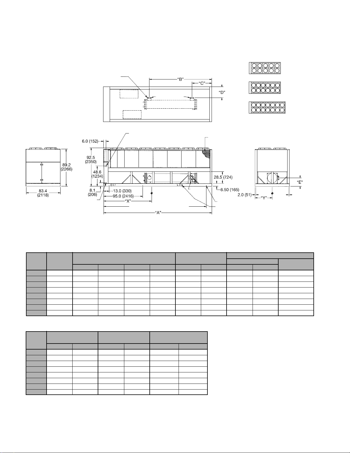
Dimensional Data
Figure 17. Unit sizes 125 thru 204
6.0 (152) for ALS125A-195A
8.0 (203) for ALS204A
Victaulic connections furnished
with grooves for victaulic
couplings by others
Air
discharge
d
Note:
1. All dimensions in inches (mm).
2. All units have (2) independent
refrigerant circuits.
3. Remove diagonal brace in way of water
outlet at installation for ALS204A only.
Compressor
#1
Compressor
#2
Power entry location this side only.
2 additional knockouts 6.0 (152)
above and below this opening
for multiple power supply
Inlet
Evaporator
2 refrigerant circuits
Outlet
Optional coil
guards
Air
discharge
d
ALS125A
ALS140A
ALS155A
ALS170A
ALS175A
ALS185A
ALS195A
ALS204A
Control
center
Power
center
Control wiring
entry knockouts
1
⁄2 (13)
for
conduit both
sides of unit
2.150 (5464) for ALS125A-170A
249.7 (6345) for ALS175A-204A
Note
#3
Unit mounting holes
2.5 (64) dia. lifting holes (4) located
from control center end (both sides)
18.6 (472) to L1 (all units) and 174.6
(4435) to L2 (ALS125A-170A) or 189.9
(4823) (ALS175A-204A).
Table 35. Unit sizes 125 thru 204
ALS
UNIT STANDARD UNIT
SIZE
125A 228.7 (5809) 117.6 (2987) 13.8 (351) 28.7 (729) 19.4 (493) 104.3 (2649) 41.7 (1059) 9920 (4500) 9600 (4355) 1652 (750)
140A 228.7 (5809) 118.5 (3010) 12.9 (328) 28.7 (729) 19.4 (493) 104.3 (2649) 41.7 (1059) 10350 (4700) 9900 (4490) 1652 (750)
155A 228.7 (5809) 118.5 (3010) 12.9 (328) 28.7 (729) 19.4 (493) 105.2 (2672) 41.7 (1059) 10670 (4840) 10250 (4650) 1652 (750)
170A 228.7 (5809) 118.5 (3010) 12.9 (328) 28.7 (729) 19.4 (493) 105.2 (2672) 41.7 (1059) 10750 (4880) 10350 (4700) 1652 (750)
175A 263.4 (6690) 153.2 (3891) 47.6 (1209) 28.7 (729) 19.4 (493) 113.1 (2873) 41.7 (1059) 11250 (5100) 10850 (4920) 1930 (876)
185A 263.4 (6690) 153.2 (3891) 47.6 (1209) 28.7 (729) 19.4 (493) 113.1 (2873) 41.7 (1059) 11250 (5100) 10850 (4920) 1930 (876)
195A 263.4 (6690) 153.2 (3891) 47.6 (1209) 27.3 (693) 20.4 (518) 115.2 (2926) 41.7 (1059) 11500 (5218) 11100 (5036) 1930 (876)
204A 263.4 (6690) 152.2 (3866) 48.5 (1232) 25.7 (653) 20.2 (513) 116.5 (2959) 41.7 (1059) 12570 (5701) 11980 (5433) 2025 (918)
LENGTH EVAPORATOR CENTER OF GRAVITY
A B C D E X Y OPERATING SHIPPING
UNIT WEIGHTS LBS (KGS)
ADDITIONAL WT.
FOR COPPER FINS
Table 35. Unit sizes 125 thru 204 (continued)
ALS
UNIT
SIZE
125A 2 65/65 10 1.5 140 (63.5) 140 (63.5)
140A 2 65/80 10 1.5 140 (63.5) 150 (68.1)
155A 2 80/80 12 1.5 150 (68.1) 150 (68.1)
170A 2 80/95 12 1.5 150 (68.1) 160 (72.6)
175A 2 80/95 14 1.5 160 (72.6) 160 (72.6)
185A 2 95/95 14 1.5 160 (72.6) 160 (72.6)
195A 2 95/95 14 1.5 170 (77.1) 170 (77.1)
204A 2 95/95 14 2.0 195 (88.5) 195 (88.5)
COMPRESSOR FANS
QTY. NOM. TONS QTY. H.P. SYSTEM #1 SYSTEM #2
OPERATING REFRIGERANT
CHARGE (R-22) LBS (KGS)
2.0 (51)
Typ.
spacing
for 1.0 (25)
diameter
isolator
mounting
hole
locations (6)
Page 24 / IM 548
Page 25

Figure 18. Unit sizes 205 thru 280
8" (203 mm) victaulic connections
furnished with grooves for victaulic
couplings by others
Note:
1. All dimensions in inches (mm).
2. All units have (3) independent refrigerant circuits.
222.1 (5641)
Compressor
#1
Inlet Outlet
Evaporator
3 refrigerant circuits
118.4 (3007)
13.7 (348)
ALS205A
ALS220A
ALS235A
ALS250A
ALS265A
ALS280A
Air
discharge
d
Control
center
Power
center
83.4
(2118)
Control wiring entry knockouts
for /
1
6.0 (152)
91.2
(2316)
1666)
94.5
(2400)
10.1
(256)
2" (13 mm) conduit
both sides of unit
65.6
Compressor
13.0 (330)
95.0 (2413)
177.0 (4496)
#2
Power entry location this side only.
2 additional knockouts 6" (152 mm)
above and below this opening for
multiple power supply
Compressor
“X”
259.0 (6579)
355.0 (9017)
#3
341.0 (8661)
Optional coil
guards
28.5 (724)
8.5 (216)
2.0 (51)
Unit mounting holes (10)
2.5" (64 mm) dia.
lifting holes (6)
located 18.6" (472 mm),
150.0" (3810 mm) and
293.0" (7442 mm) from
control center end (both sides)
Air
discharge
d
“Y”
22.0 (559)
2.0 (51 mm)
typ. spacing
for 1" (25 mm)
dia. isolation
mounting
holes (10)
Table 36. Unit sizes 205 thru 280
CENTER OF GRAVITY UNIT WEIGHTS
ALS
UNIT
SIZE
X Y OPERATING SHIPPING
IN. MM IN. MM LBS. KGS. LBS. KGS. LBS. KGS. LBS. KGS. LBS. KGS. LBS. KGS.
ADDITIONAL WEIGHT FOR
UNITS WITH COPPER FIN COILS
205A 146.7 3,726 41.7 1,059 15,930 7,224 15,250 6,916 2,478 1,124 3 65/65/80 16 1.5 140 63.5 140 63.5 150 68.1
220A 146.7 3,726 41.7 1,059 15,980 7,247 15,330 6,952 2,478 1,124 3 65/80/80 16 1.5 140 63.5 150 68.1 150 68.1
235A 146.7 3,726 41.7 1,059 16,180 7,338 15,530 7,043 2,478 1,124 3 80/80/80 18 1.5 150 68.1 150 68.1 150 68.1
250A 146.7 3,726 41.7 1,059 16,200 7,347 15,600 7,075 2,478 1,124 3 80/80/95 18 1.5 150 68.1 150 68.1 160 72.6
265A 146.7 3,726 41.7 1,059 16,200 7,347 15,600 7,075 2,478 1,124 3 80/95/95 18 1.5 150 68.1 160 72.6 160 72.6
280A 146.7 3,726 41.7 1,059 16,250 7,370 15,650 7,098 2,478 1,124 3 95/95/95 18 1.5 160 72.6 160 72.6 160 72.6
COMPRESSORS FANS OPERATING REFRIGERANT CHARGE (R-22)
QTY. NOM. TONS QTY. H.P.
SYSTEM #1 SYSTEM #2 SYSTEM #3
IM 548 / Page 25
Page 26

Figure 19. Unit sizes 300 thru 340
8.0 (203) victaulic connections
furnished with grooves for victaulic
couplings by others
Note:
1. All dimensions in inches (mm).
2. All units have (4) independent refrigerant circuits.
189.8 (4821)
86.1 (2187)
discharge
Control
center
Air
d
Power
center
83.4
(2118)
for /
both sides of unit
6.0 (152)
94.5
(2400)
91.2
(2316)
10.1
(256)
Control wiring
entry knockouts
1
2
(13) conduit
65.6
(1666)
Compressor
#1
Compressor
#2
Power entry location this side only.
2 additional knockouts 6 (152) above and below
this opening for multiple power supply
13.0 (330)
95.0 (2413)
177.0 (4496)
Compressor
#3
Compressor
#4
“X”
259.0 (6579)
375.7 (9543)
Inlet
Evaporator
4 refrigerant circuits
389.7 (9898)
Outlet
2.5 (64) dia. lifting holes (6)
located 18.6 (472), 167.0 (4242)
and 320.0 (8128) from control
center end (both sides)
Unit isolator/mounting hole locations (10)
23.4 (594)
Optional
coil guards
8.5 (216)
discharge
2.0
“Y”
28.5 (724)
Air
d
22.0 (559)
2.0 (51)
typ. spacing
for 1.0 (25) diameter
isolator/mounting
hole locations (10)
Table 37. Unit sizes 300 thru 340
CENTER OF GRAVITY UNIT WEIGHTS
ALS
UNIT X Y OPERATING SHIPPING
SIZE
IN. MM IN. MM LBS. KGS. LBS. KGS. LBS. KGS.
ADD’L WEIGHT FOR UNITS
WITH COPPER FIN COILS
300A 166.9 4239 41.7 1059 21,250 9637 20,300 9206 3,671 1665 4 65/65/80/80 20 2.0 155 70.3 155 70.3 160 72.6 160 72.6
315A 166.9 4239 41.7 1059 21,250 9637 20,300 9206 3,671 1665 4 65/80/80/80 20 2.0 155 70.3 160 72.6 160 72.6 160 72.6
330A 166.9 4239 41.7 1059 21,320 9669 20,400 9252 3,671 1665 4 80/80/80/80 20 2.0 160 72.6 160 72.6 160 72.6 160 72.6
340A 166.9 4239 41.7 1059 21,320 9669 20,400 9252 3,671 1665 4 80/80/80/95 20 2.0 160 72.6 160 72.6 160 72.6 170 77.1
COMPRESSORS FANS OPERATING REFRIGERANT CHARGE (R-22)
QTY.
NOM.
TONS
QTY. HP
SYST. #1 SYST. #2 SYST. #3 SYST. #4
LBS. KGS. LBS. KGS. LBS. KGS. LBS. KGS.
Page 26 / IM 548
Page 27

Figure 20. Unit sizes 360 thru 380
Note:
1. All dimensions in inches (mm).
2. All units have (4) independent refrigerant circuits.
3. Remove brace in way of water outlet at installation.
discharge
Control
center
Air
d
Power
center
83.4
(2118)
entry knockouts
for
both sides of unit
6.0 (152)
94.5
(2400)
91.2
(2316)
(256)
Control wiring
1
/2 (13) conduit
8.0 (203) victaulic connections
furnished with grooves for victaulic
couplings by others
Compressor
#1
Compressor
#2
Power entry location this side only.
2 additional knockouts 6 (152) above and below
this opening for multiple power supply
65.6
(1666)
10.1
13.0 (330)
95.0 (2413)
177.0 (4496)
Compressor
“X”
259.0 (6579)
#3
Compressor
#4
341.0 (8661)
445.0 (11303)
459.0 (11659)
259.2 (6584)
155.5 (3950)
Inlet Outlet
Evaporator
4 refrigerant circuits
Note #3
2.5 (64) dia. lifting holes (8)
located 18.6 (472), 146.6 (3724)
274.6 (6975) and 403.8 (10257)
from control center end (both sides)
Unit isolator/mounting hole locations (12)
23.4 (594)
Optional
coil guards
28.5 (724)
8.5 (216)
Air
discharge
d
2.0
“Y”
2.0 (51)
typ. spacing for
1.0 (25) diameter
isolator/mounting
hole locations (12)
22.0 (559)
Table 38. Unit sizes 360 thru 380
CENTER OF GRAVITY UNIT WEIGHTS
ALS
UNIT X Y OPERATING SHIPPING
SIZE
IN. MM IN. MM LBS. KGS. LBS. KGS. LBS. KGS.
ADD’L WEIGHT FOR UNITS
WITH COPPER FIN COILS
360A 185.0 4699 41.7 1059 22,92010395 22,000 9977 4,406 1998 4 80/80/95/95 24 2.0 175 79.4 175 79.4 180 81.6 180 81.6
370A 185.0 4699 41.7 1059 22,97010417 22,050 10000 4,406 1998 4 80/95/95/95 24 2.0 175 79.4 180 81.6 180 81.6 180 81.6
380A 185.0 4699 41.7 1059 23,02010440 22,100 10023 4,406 1998 4 95/95/95/95 24 2.0 180 81.6 180 81.6 180 81.6 180 81.6
COMPRESSORS FANS OPERATING REFRIGERANT CHARGE (R-22)
QTY.
NOM.
TONS
QTY. HP
SYST. #1 SYST. #2 SYST. #3 SYST. #4
LBS. KGS. LBS. KGS. LBS. KGS. LBS. KGS.
IM 548 / Page 27
Page 28

Field Wiring
General
Wiring must comply with all applicable codes and ordinances. Warranty is voided if wiring is not in
accordance with specifications. An open fuse indicates a short, ground, or overload. Before replacing a
fuse or restarting a compressor or fan motor, the trouble must be found and corrected.
Copper wire is required for all power lead terminations at the unit and copper must be used for all other
wiring to the unit.
ALS units may be ordered with main power wiring for either single or multiple point power connection.
If single point power connection is ordered, a single large power terminal block is provided and wiring
within the unit is sized in accordance with the National Electrical Code. A single field supplied
disconnect is required. An optional factory mounted transformer for the 115 volt control circuit may be
provided.
If multiple point power wiring is ordered, two power connections (125 thru 204) and (300 thru 380) or
three power connections (205 thru 280) are required and wiring within the unit is sized in accordance
with the National Electrical Code. A separate circuit is required for the 115 volt control circuit. Separate
field supplied disconnects are required for each electrical circuit.
It may be desirable to have the unit cooler heater on a separate disconnect switch from the main unit
power supply so that the unit may be shut down without defeating the freeze protection provided by the
cooler heater.
ALS unit compressors are single direction rotation
compressors. For this reason proper phasing of
electrical power is important. Electrical phasing must
be A, B, C for electrical phases 1, 2 and 3
(A=L1,B=L2,C=L3). Units supplied with single point
factory power connections will include one
MotorSaver® phase failure, phase reversal protective
device that will prevent operation of the unit with
incorrect power phasing. The MotorSaver is factory
wired and tested. Do not alter the wiring to the
MotorSaver.
Page 28 / IM 548
Multiple point power wired units will include two (125 thru 204) and (300 thru 380) or three (205 thru
280) MotorSaver safety controls (one for each power supply), and the contractor is cautioned to not apply
power until the phasing is verified with a phase sequence meter.
Internal power wiring to the compressors for the
single point versus the multiple point option are
different. It is imperative that the proper field wiring
be installed according to the way the unit is built.
Page 29

Overload Dial Setting
For units with 1 contactor and 1 overload per compressor:
The Overload must be set at a “Must Hold Dial Setting” equal to 125% of the compressor RLA listed
on the unit data plate.
For units with 2 contactors and 2 overloads per compressor:
The Overload must be set at a “Must Hold Dial Setting” equal to 125% of half the compressor RLA
listed on the unit data plate.
Notes:
The “Must Trip Amps” is 12% higher than the “Must Hold Dial Setting”.
The accuracy of the Overload Setting is ±2%.
Table 39. Electrical data single point (70 thru 100)
ALS
UNIT VOLTS HZ
SIZE
208 335 3 400 1 3.0 500 500
230 307 3 350 1 2.5 400 500
070A 380 60 185 3 3/0 1 2.0 250 300
460 153 3 2/0 1 1.5 200 250
575 124 3 #1 1 1.5 175 200
208 410 3 600 1 3.0 500 700
230 375 3 500 1 3.0 500 600
080A 380 60 227 3 4/0 1 2.0 300 350
460 187 3 3/0 1 1.5 250 300
575 150 3 1/0 1 1.5 200 250
208 475 6 350 2 2.5 600 800
230 434 6 300 2 2.5 600 700
090A 380 60 262 3 300 1 2.5 350 450
460 216 3 4/0 1 2.0 300 350
575 173 3 2/0 1 1.5 225 250
208 475 6 350 2 2.5 600 800
230 434 6 300 2 2.5 600 700
100A 380 60 262 3 300 1 2.5 350 450
460 216 3 4/0 1 2.0 300 350
575 173 3 2/0 1 1.5 225 250
Table based on 75°C field wire per NEC.
MINIMUM
CIRCUIT
AMPACITY
(MCA)
FIELD WIRE HUB
QTY.
POWER SUPPLY FIELD FUSE SIZE
WIRE
GAUGE SIZE
QTY.
NOMINAL
RECOM-
MENDED
MAXIMUM
IM 548 / Page 29
Page 30

Wire Sizing Ampacities
Table 40. Electrical data single point (125 thru 204)
ALS
UNIT VOLTS HZ
SIZE
208 598 6 350 2 2.5 700 800
125A 380 60 331 3 400 1 3.0 400 450
140A 380 60 372 3 500 1 3.0 450 500
155A 380 60 412 6 #4/0 2 2.0 500 500
170A 380 60 441 6 #4/0 2 2.0 500 600
175A 380 60 448 6 250 2 2.5 500 600
185A 380 60 471 6 250 2 2.5 500 600
195A 380 60 471 6 250 2 2.5 500 600
204A 380 60 481 6 250 2 2.5 500 600
*Field wire size values apply to 90°C rated wire per NEC.
230 548 6 300 2 2.5 600 700
460 273 3 300 1 2.5 300 350
575 221 3 4/0 1 2.0 250 300
208 673 6 500 2 3.0 800 800
230 616 6 350 2 2.5 700 800
460 307 3 350 1 2.5 400 400
575 247 3 250 1 2.5 300 350
208 745 6 500 2 3.0 800 1000
230 682 6 500 2 3.0 800 800
460 340 3 500 1 3.0 400 450
575 273 3 300 1 2.5 300 350
208 799 6 600 2 3.0 1000 1000
230 730 6 500 2 3.0 800 1000
460 364 3 500 1 3.0 450 500
575 292 3 350 1 2.5 350 400
208 810 6 600 2 3.0 1000 1000
230 741 6 500 2 3.0 1000 1000
460 369 3 500 1 3.0 450 500
575 296 3 350 1 2.5 350 400
208* 853* 6 600* 2 3.0 1000 1000
230 779 6 600 2 3.0 1000 1000
460 388 6 #3/0 2 2.0 450 500
575 311 3 400 1 2.5 350 400
208* 853* 6 600* 2 3.0 1000 1000
230 779 6 600 2 3.0 1000 1000
460 388 6 #3/0 2 2.0 450 500
575 311 3 400 1 2.5 350 400
208* 881* 6 600* 2 3.0 1000 1200
230 799 6 600 2 3.0 1000 1000
460 399 6 #3/0 2 2.0 500 500
575 321 3 400 1 2.5 400 400
MINIMUM
CIRCUIT
AMPACITY
(MCA)
FIELD WIRE HUB
QTY.
POWER SUPPLY FIELD FUSE SIZE
WIRE
GAUGE SIZE
QTY.
NOMINAL
RECOM-
MENDED
MAXIMUM
Page 30 / IM 548
Page 31

Table 41. Electrical data single point (205 thru 380)
ALS
UNIT VOLTS HZ
SIZE
205A 460 60 433 6 #4/0 2 2.0 500 500
220A 460 60 460 6 #4/0 2 2.0 500 500
235A 460 60 492 6 250 2 2.0 600 600
250A 460 60 516 6 300 2 2.0 600 600
265A 460 60 535 6 300 2 2.0 600 600
280A 460 60 554 6 300 2 2.0 600 700
300A 460 60 596 6 350 2 2.5 700 700
315A 460 60 623 6 400 2 2.5 700 700
330A 460 60 650 6 400 2 2.5 700 700
340A 460 60 674 6 500 2 3.0 800 800
360A 460 60 707 6 500 2 3.0 800 800
370A 460 60 726 6 500 2 3.0 800 800
380A 460 60 745 6 500 2 3.0 800 800
*Table based on 75°C field wire except for 380V ALS360, 370 and 380 which require 90°C field wire.
380 525 6 300 2 2.0 600 600
575 349 2 #3/0 2 1.5 400 450
380 558 6 300 2 2.0 700 700
575 370 6 #3/0 2 1.5 450 450
380 597 6 350 2 2.5 700 700
575 395 6 #3/0 2 1.5 450 500
380 626 6 400 2 2.5 700 800
575 414 6 #4/0 2 2.0 500 500
380 649 6 400 2 2.5 800 800
575 429 6 #4/0 2 2.0 500 500
380 672 6 500 2 3.0 800 800
575 444 6 #4/0 2 2.0 500 500
380 723 6 500 2 3.0 800 800
575 481 6 250 2 2.0 500 500
380 756 6 500 2 3.0 800 800
575 502 6 250 2 2.0 600 600
380 789 6 600 2 3.0 800 800
575 523 6 300 2 2.0 600 600
380 818 6 600 2 3.0 1000 1000
575 542 6 300 2 2.0 600 600
380* 859 6 600 2 3.0 1000 1000
575 569 6 300 2 2.0 600 600
380* 882 6 600 2 3.0 1000 1000
575 584 6 350 2 2.5 700 700
380* 905 6 600 2 3.0 1000 1000
575 599 6 350 2 2.5 700 700
MINIMUM
CIRCUIT
AMPACITY
(MCA)
FIELD WIRE HUB
QTY.
POWER SUPPLY FIELD FUSE SIZE
WIRE
GAUGE SIZE
QTY.
NOMINAL
RECOM-
MENDED
MAXIMUM
IM 548 / Page 31
Page 32

Table 42. Electrical data multiple point (125 thru 204)
ELECTRICAL CIRCUIT #1 ELECTRICAL CIRCUIT #2
ALS
UNIT VOLTS HZ
SIZE
208 329 3 400 1 3.0 400 500 329 3 400 1 3.0 400 500
125A 380 60 182 3 #3/0 1 2.0 225 300 182 3 #3/0 1 2.0 225 300
140A 380 60 182 3 #3/0 1 2.0 225 300 223 3 #4/0 1 2.0 300 350
155A 380 60 226 3 #4/0 1 2.0 300 350 226 3 #4/0 1 2.0 300 350
170A 380 60 226 3 #4/0 1 2.0 300 350 255 3 250 1 2.5 350 400
175A 380 60 230 3 #4/0 1 2.0 300 350 259 3 300 1 2.5 350 400
185A 380 60 259 3 300 1 2.5 350 400 259 3 300 1 2.5 350 400
195A 380 60 259 3 300 1 2.5 350 400 259 3 300 1 2.5 350 400
204A 380 60 284 3 300 1 2.5 400 450 264 3 300 1 2.5 400 450
230 301 3 350 1 2.5 400 500 301 3 350 1 2.5 400 500
460 150 3 #1/0 1 1.5 200 250 150 3 #1/0 1 1.5 200 250
575 122 3 #1 1 1.5 150 200 122 3 #1 1 1.5 150 200
208 329 3 400 1 3.0 400 500 404 6 #4/0 2 2.0 500 700
230 301 3 350 1 2.5 400 500 369 3 500 1 3.0 500 600
460 150 3 #1/0 1 1.5 200 250 184 3 #3/0 1 2.0 250 300
575 122 3 #1 1 1.5 150 200 148 3 #1/0 1 1.5 200 250
208 410 6 #4/0 2 2.0 500 700 410 6 #4/0 2 2.0 500 700
230 375 3 500 1 3.0 500 600 375 3 500 1 3.0 500 600
460 187 3 #3/0 1 2.0 250 300 187 3 #3/0 1 2.0 250 300
575 150 3 #1/0 1 1.5 200 250 150 3 #1/0 1 1.5 200 250
208 410 6 #4/0 2 2.0 500 700 464 6 250 2 2.5 600 800
230 375 3 500 1 3.0 500 600 423 6 #4/0 2 2.0 500 700
460 187 3 #3/0 1 2.0 250 300 211 3 #4/0 1 2.0 250 350
575 150 3 #1/0 1 1.5 200 250 169 3 #2/0 1 1.5 225 250
208 416 6 #4/0 2 2.0 500 700 470 6 250 2 2.5 600 800
230 381 6 #3/0 2 2.0 500 600 429 6 #4/0 2 2.0 500 700
460 190 3 #3/0 1 2.0 250 300 214 3 #4/0 1 2.0 250 350
575 152 3 #2/0 1 1.5 200 250 171 3 #2/0 1 1.5 225 250
208 470 6 250 2 2.5 600 800 470 6 250 1 2.5 600 800
230 429 6 #4/0 2 2.0 500 700 429 6 #4/0 1 2.0 500 700
460 214 3 #4/0 1 2.0 250 350 214 3 #4/0 1 2.0 250 350
575 171 3 #2/0 1 1.5 225 250 171 3 #2/0 1 1.5 225 250
208 470 6 250 2 2.5 600 800 470 6 250 1 2.5 600 800
230 429 6 #4/0 2 2.0 500 700 429 6 #4/0 1 2.0 500 700
460 214 3 #4/0 1 2.0 250 350 214 3 #4/0 1 2.0 250 350
575 171 3 #2/0 1 1.5 225 250 171 3 #2/0 1 1.5 225 250
208 484 6 250 2 2.5 700 800 484 6 250 2 2.5 700 800
230 439 6 #4/0 2 2.0 600 700 439 6 #4/0 2 2.0 600 700
460 219 3 #4/0 1 2.0 300 350 219 3 #4/0 1 2.0 300 350
575 176 3 #3/0 1 2.0 250 300 176 3 #3/0 1 2.0 250 300
MINIMUM
CIRCUIT
AMPS
(MCA)
POWER SUPPLY FIELD FUSING
FIELD WIRE HUB
WIRE HUB
QTY.
GAUGE
QTY.
SIZE
REC. MAX.
FUSE FUSE
SIZE SIZE
MINIMUM
CIRCUIT
AMPS
(MCA)
POWER SUPPLY FIELD FUSING
FIELD WIRE HUB
WIRE HUB
QTY.
GAUGE
QTY.
SIZE
REC. MAX.
FUSE FUSE
SIZE SIZE
Page 32 / IM 548
Page 33

Table 43. Electrical data multiple point (205 thru 280)
ELECTRICAL CIRCUIT #1 ELECTRICAL CIRCUIT #2
ALS
UNIT VOLTS HZ
SIZE
208 329 3 400 1 2.5 400 500 329 3 400 1 2.5 400 500
205A 380 60 182 3 #3/0 1 1.5 250 300 182 3 #3/0 1 1.5 250 300
220A 380 60 182 3 #3/0 1 1.5 250 300 223 3 #4/0 1 2 300 350
235A 380 60 227 3 #4/0 1 2 300 350 227 3 #4/0 1 2 300 350
250A 380 60 227 3 #4/0 1 2 300 350 227 3 #4/0 1 2 300 350
265A 380 60 227 3 #4/0 1 2 300 350 256 3 250 1 2 350 400
280A 380 60 256 3 250 1 2 350 400 256 3 250 1 2 350 400
Note: Electrical circuit #3 is continued on next page.
230 302 3 350 1 2.5 400 500 302 3 350 1 2.5 400 500
460 150 3 #1/0 1 1.25 200 250 150 3 #1/0 1 1.25 200 250
575 122 3 #1/0 1 1.25 175 200 122 3 #1/0 1 1.25 175 200
208 329 3 400 1 2.5 400 500 410 6 300 1 3 600 700
230 302 3 350 1 2.5 400 500 375 6 250 1 3 500 600
460 150 3 #1/0 1 1.25 200 250 187 3 #3/0 1 1.5 250 300
575 122 3 #1/0 1 1.25 175 200 150 3 #1/0 1 1.25 200 250
208 410 6 300 1 3 600 700 410 6 300 1 3 600 700
230 375 6 250 1 3 500 600 375 6 250 1 3 500 600
460 187 3 #3/0 1 1.5 250 300 187 3 #3/0 1 1.5 250 300
575 150 3 #1/0 1 1.25 200 250 150 3 #1/0 1 1.25 200 250
208 410 6 300 1 3 600 700 410 6 300 1 3 600 700
230 375 6 250 1 3 500 600 375 6 250 1 3 500 600
460 187 3 #3/0 1 1.5 250 300 187 3 #3/0 1 1.5 250 300
575 150 3 #1/0 1 1.25 200 250 150 3 #1/0 1 1.25 200 250
208 410 6 300 1 3 600 700 464 6 350 1 3.5 700 800
230 375 6 250 1 3 500 600 423 6 300 1 3 600 700
460 187 3 #3/0 1 1.5 250 300 211 3 #4/0 1 2 300 350
575 150 3 #1/0 1 1.25 200 250 170 3 #2/0 1 1.5 250 250
208 464 6 350 1 3.5 700 800 464 6 350 1 3.5 700 800
230 423 6 300 1 3 600 700 423 6 300 1 3 600 700
460 211 3 #4/0 1 2 300 350 211 3 #4/0 1 2 300 350
575 170 3 #2/0 1 1.5 250 250 170 3 #2/0 1 1.5 250 250
MINIMUM
CIRCUIT
AMPS
(MCA)
POWER SUPPLY FIELD FUSING
FIELD WIRE HUB
WIRE HUB
QTY.
GAUGE
QTY.
SIZE
REC. MAX.
FUSE FUSE
SIZE SIZE
MINIMUM
CIRCUIT
AMPS
(MCA)
POWER SUPPLY FIELD FUSING
FIELD WIRE HUB
WIRE HUB
QTY.
GAUGE
QTY.
SIZE
REC. MAX.
FUSE FUSE
SIZE SIZE
IM 548 / Page 33
Page 34

Table 43. Electrical data multiple point (205 thru 280 continued)
ELECTRICAL CIRCUIT #3
ALS
UNIT VOLTS HZ
SIZE
208 410 6 300 1 3.0 600 700
205A 380 60 227 3 #4/0 1 2.0 300 350
220A 380 60 227 3 #4/0 1 2.0 300 350
235A 380 60 227 3 #4/0 1 2.0 300 350
250A 380 60 256 3 250 1 2.0 350 400
265A 380 60 256 3 250 1 2.0 350 400
280A 380 60 256 3 250 1 2.0 350 400
230 375 6 250 1 3.0 500 600
460 187 3 #3/0 1 1.5 250 300
575 150 3 #1/0 1 1.25 200 250
208 410 6 300 1 3.0 600 700
230 375 6 250 1 3.0 500 600
460 187 3 #3/0 1 1.5 250 300
575 150 3 #1/0 1 1.25 200 250
208 410 6 300 1 3.0 600 700
230 375 6 250 1 3.0 500 600
460 187 3 #3/0 1 1.5 250 300
575 150 3 #1/0 1 1.25 200 250
208 464 6 350 1 3.5 700 800
230 423 6 300 1 3.0 600 700
460 211 3 #4/0 1 2.0 300 350
575 170 3 #2/0 1 1.5 250 250
208 464 6 350 1 3.5 700 800
230 423 6 300 1 3.0 600 700
460 211 3 #4/0 1 2.0 300 350
575 170 3 #2/0 1 1.5 250 250
208 464 6 350 1 3.5 700 800
230 423 6 300 1 3.0 600 700
460 211 3 #4/0 1 2.0 300 350
575 170 3 #2/0 1 1.5 250 250
MINIMUM
CIRCUIT
AMPS
(MCA)
POWER SUPPLY FIELD FUSING
FIELD WIRE HUB
WIRE HUB
QTY.
GAUGE
QTY.
SIZE
REC. MAX.
FUSE FUSE
SIZE SIZE
Page 34 / IM 548
Page 35

Table 44. Electrical data multiple point (300 thru 380)
ELECTRICAL CIRCUIT #1 (COMP’S #1 & #3) ELECTRICAL CIRCUIT #2 (COMP’S #2 & #4)
ALS
UNIT VOLTS HZ
SIZE AMPS
208 693 6 500 2 3.0 800 800 693 6 500 2 3.0 800 800
230 630 6 400 2 2.5 800 800 630 6 400 2 2.5 800 800
300A 380 60 382 6 250 1 3.0 450 500 382 6 250 1 3.0 450 500
460 315 3 400 1 2.5 400 450 315 3 400 1 2.5 400 450
575 254 3 250 1 2.0 350 350 254 3 250 1 2.0 350 350
208 693 6 500 2 3.0 800 800 753 6 500 2 3.0 1000 1000
230 630 6 400 2 2.5 800 800 684 6 400 2 3.0 800 800
315A 380 60 382 6 250 1 3.0 450 500 415 6 300 1 3.0 500 500
460 315 3 400 1 2.5 400 450 342 3 400 1 3.0 400 450
575 254 3 250 1 2.0 350 350 275 3 250 1 2.0 350 350
208 753 6 500 2 3.0 1000 1000 753 6 500 2 3.0 1000 1000
230 684 6 500 2 3.0 800 800 684 6 500 2 3.0 800 800
330A 380 60 415 6 300 1 3.0 500 500 415 6 300 1 3.0 500 500
460 342 3 500 1 3.0 400 450 342 3 500 1 3.0 400 450
575 275 3 300 1 2.0 350 350 275 3 300 1 2.0 350 350
208 753 6 500 2 3.0 1000 1000 807 6 600 2 3.0 1000 1000
230 684 6 500 2 3.0 800 800 732 6 500 2 3.0 1000 1000
340A 380 60 415 6 300 1 3.0 500 500 444 6 300 1 3.0 500 600
460 342 3 500 1 3.0 400 450 366 3 500 1 3.0 450 500
575 275 3 300 1 2.0 350 350 294 3 350 1 2.5 350 400
208 822 6 600 2 3.0 1000 1000 822 6 600 2 3.0 1000 1000
230 746 6 500 2 3.0 1000 1000 746 6 500 2 3.0 1000 1000
360A 380 60 453 6 300 1 3.0 500 600 453 6 300 1 3.0 500 600
460 373 3 500 1 3.0 450 500 373 3 500 1 3.0 450 500
575 300 3 350 1 2.5 400 400 300 3 350 1 2.5 400 400
208* 822 6 600 2 3.0 1000 1000 865 6 600 2 3.0 1000 1000
230 746 6 500 2 3.0 1000 1000 784 6 600 2 3.0 1000 1000
370A 380 60 453 6 300 1 3.0 500 600 476 6 350 1 3.5 500 600
460 373 3 500 1 3.0 450 500 392 3 600 1 3.0 450 500
575 300 3 350 1 2.5 400 400 315 3 400 1 2.5 400 400
208* 865 6 600 2 3.0 1000 1000 865 6 600 2 3.0 1000 1000
230 784 6 600 2 3.0 1000 1000 784 6 600 2 3.0 1000 1000
380A 380 60 476 6 350 1 3.5 500 600 476 6 350 1 3.5 500 600
460 392 3 600 1 3.0 450 500 392 3 600 1 3.0 450 500
575 315 3 400 1 2.5 400 400 315 3 400 1 2.5 400 400
MINIMUM
CIRCUIT
(MCA)
POWER SUPPLY FIELD FUSING
FIELD WIRE HUB
WIRE HUB
QTY.
GAUGE
QTY.
SIZE
REC. MAX.
FUSE FUSE
SIZE SIZE
MINIMUM
CIRCUIT
AMPS
(MCA)
POWER SUPPLY FIELD FUSING
FIELD WIRE HUB
WIRE HUB
QTY.
GAUGE
QTY.
SIZE
REC. MAX.
FUSE FUSE
SIZE SIZE
Compressor and Condenser Fan Motors
Table 45. Compressor and condenser fan motor amp draw (70 thru 100)
ALS
UNIT VOLTS HZ
SIZE
208 240 5.8 6 23.7 1459 934
230 218 5.8 6 21.4 1628 1042
070A 380 60 132 3.4 6 14.4 943 604
460 109 2.8 6 10.7 764 489
575 88 2.3 6 11.5 589 377
208 300 5.8 6 23.7 1459 934
230 272 5.8 6 21.4 1628 1042
080A 380 60 165 3.4 6 14.4 943 604
460 136 2.8 6 10.7 764 489
575 109 2.3 6 11.5 589 377
208 343 5.8 8 23.7 1459 934
230 310 5.8 8 21.4 1628 1042
090A 380 60 188 3.4 8 14.4 943 604
460 155 2.8 8 10.7 764 489
575 124 2.3 8 11.5 589 377
208 343 5.8 8 23.7 1459 934
230 310 5.8 8 21.4 1628 1042
100A 380 60 188 3.4 8 14.4 943 604
460 155 2.8 8 10.7 764 489
575 124 2.3 8 11.5 589 377
RATED LOAD AMPS
COMPRESSOR
FAN
MOTORS
FLA
(EACH)
NO. OF
FAN
MOTORS
FAN
MOTORS
(EACH)
LOCKED ROTOR AMPS
COMPRESSOR
ACROSS-THE-LINE REDUCED INRUSH
IM 548 / Page 35
Page 36

Table 46. Compressor and condenser fan motor amp draw (125 thru 204)
ALS
UNIT VOLTS H
SIZE
208 240 240 5.8 10 23.7 1459 934
125A 380 60 132 132 3.4 10 14.4 943 604
140A 380 60 132 165 3.4 10 14.4 943 604
155A 380 60 165 165 3.4 12 14.4 943 604
170A 380 60 165 188 3.4 12 14.4 943 604
175A 380 60 165 188 3.4 14 14.4 943 604
185A 380 60 188 188 3.4 14 14.4 943 604
195A 380 60 188 188 3.4 14 14.4 943 604
204A 380 60 188 188 4.1 14 20.0 943 604
230 218 218 5.8 10 21.4 1628 1042
460 109 109 2.8 10 10.7 764 489
575 88 88 2.3 10 11.5 589 377
208 240 300 5.8 10 23.7 1459 934
230 218 272 5.8 10 21.4 1628 1042
460 109 136 2.8 10 10.7 764 489
575 88 109 2.3 10 11.5 589 377
208 300 300 5.8 12 23.7 1459 934
230 272 272 5.8 12 21.4 1628 1042
460 136 136 2.8 12 10.7 764 489
575 109 109 2.3 12 11.5 589 377
208 300 343 5.8 12 23.7 1459 934
230 272 310 5.8 12 21.4 1628 1042
460 136 155 2.8 12 10.7 764 489
575 109 124 2.3 12 11.5 589 377
208 300 343 5.8 14 23.7 1459 934
230 272 310 5.8 14 21.4 1628 1042
460 136 155 2.8 14 10.7 764 489
575 109 124 2.3 14 11.5 589 377
208 343 343 5.8 14 23.7 1459 934
230 310 310 5.8 14 21.4 1628 1042
460 155 155 2.8 14 10.7 764 489
575 124 124 2.3 14 11.5 589 377
208 343 343 5.8 14 23.7 1459 934
230 310 310 5.8 14 21.4 1628 1042
460 155 155 2.8 14 10.7 764 489
575 124 124 2.3 14 11.5 589 377
208 343 343 7.8 14 30.5 1459 934
230 310 310 7.2 14 27.6 1628 1042
460 155 155 3.6 14 13.8 764 489
575 124 124 3.0 14 11.5 589 377
RATED LOAD AMPS
COMPRESSOR
Z
NO. 1 NO. 2
FAN
MOTORS
FLA
(EACH)
NO. OF
FAN
MOTORS
FAN
MOTORS
(EACH)
LOCKED ROTOR AMPS
COMPRESSOR
ACROSS-THE-LINE REDUCED INRUSH
Page 36 / IM 548
Page 37

Table 47. Compressor and condenser fan motor amp draw (205 thru 280)
ALS
UNIT VOLTAGE HZ
SIZE
208 240 240 300 5.8 16 23.7 1459 934
205A 380 60 132 132 165 3.4 16 14.4 943 604
220A 380 60 132 165 165 3.4 16 14.4 943 604
235A 380 60 165 165 165 3.4 18 14.4 943 604
250A 380 60 165 165 188 3.4 18 14.4 943 604
265A 380 60 165 188 188 3.4 18 14.4 943 604
280A 380 60 188 188 188 3.4 18 14.4 943 604
230 218 218 272 5.8 16 21.4 1628 1042
460 109 109 136 2.8 16 10.7 764 489
575 88 88 109 2.3 16 11.5 589 377
208 240 300 300 5.8 16 23.7 1459 934
230 218 272 272 5.8 16 21.4 1628 1042
460 109 136 136 2.8 16 10.7 764 489
575 88 109 109 2.3 16 11.5 589 377
208 300 300 300 5.8 18 23.7 1459 934
230 272 272 272 5.8 18 21.4 1628 1042
460 136 136 136 2.8 18 10.7 764 489
575 109 109 109 2.3 18 11.5 589 377
208 300 300 343 5.8 18 23.7 1459 934
230 272 272 310 5.8 18 21.4 1628 1042
460 136 136 155 2.8 18 10.7 764 489
575 109 109 124 2.3 18 11.5 589 377
208 300 343 343 5.8 18 23.7 1459 934
230 272 310 310 5.8 18 21.4 1628 1042
460 136 155 155 2.8 18 10.7 764 489
575 109 124 124 2.3 18 11.5 589 377
208 343 343 343 5.8 18 23.7 1459 934
230 310 310 310 5.8 18 21.4 1628 1042
460 155 155 155 2.8 18 10.7 764 489
575 124 124 124 2.3 18 11.5 589 377
RATED LOAD AMPS
COMPRESSORS
NO. 1 NO. 2 NO. 3
FAN
MOTORS
FLA
(EACH)
NO. OF
FAN
MOTORS
FAN
MOTORS
(EACH)
LOCKED ROTOR AMPS
PER COMPRESSOR
ACROSS-THE-LINE REDUCED IN RUSH
IM 548 / Page 37
Page 38

Table 48. Compressor and condenser fan motor amp draw (300 thru 380)
ALS
UNIT VOLTS HZ
SIZE
208 240 240 300 300 7.8 20 30.5 1459 934
300A 380 60 132 132 165 165 4.1 20 20.0 943 604
315A 380 60 132 165 165 165 4.1 20 20.0 943 604
330A 380 60 165 165 165 165 4.1 20 20.0 943 604
340A 380 60 165 165 165 188 4.1 20 20.0 943 604
360A 380 60 165 165 188 188 4.1 24 20.0 943 604
370A 380 60 165 188 188 188 4.1 24 20.0 943 604
380A 380 60 188 188 188 188 4.1 24 20.0 943 604
230 218 218 272 272 7.2 20 27.6 1628 1042
460 109 109 136 136 3.6 20 13.8 764 489
575 88 88 109 109 3.0 20 11.5 589 377
208 240 300 300 300 7.8 20 30.5 1459 934
230 218 272 272 272 7.2 20 27.6 1628 1042
460 109 136 136 136 3.6 20 13.8 764 489
575 88 109 109 109 3.0 20 11.5 589 377
208 300 300 300 300 7.8 20 30.5 1459 934
230 272 272 272 272 7.2 20 27.6 1628 1042
460 136 136 136 136 3.6 20 13.8 764 489
575 109 109 109 109 3.0 20 11.5 589 377
208 300 300 300 343 7.8 20 30.5 1459 934
230 272 272 272 310 7.2 20 27.6 1628 1042
460 136 136 136 155 3.6 20 13.8 764 489
575 109 109 109 124 3.0 20 11.5 589 377
208 300 300 343 343 7.8 24 30.5 1459 934
230 272 272 310 310 7.2 24 27.6 1628 1042
460 136 136 155 155 3.6 24 13.8 764 489
575 109 109 124 124 3.0 24 11.5 589 377
208 300 343 343 343 7.8 24 30.5 1459 934
230 272 310 310 310 7.2 24 27.6 1628 1042
460 136 155 155 155 3.6 24 13.8 764 489
575 109 124 124 124 3.0 24 11.5 589 377
208 343 343 343 343 7.8 24 30.5 1459 934
230 310 310 310 310 7.2 24 27.6 1628 1042
460 155 155 155 155 3.6 24 13.8 764 489
575 124 124 124 124 3.0 24 11.5 589 377
RATED LOAD AMPS
COMPRESSORS
NO. 1 NO. 2 NO. 3 NO. 4
FAN
MOTORS
FLA
(EACH)
NO. OF
FAN
MOTORS
FAN
MOTORS
(EACH)
LOCKED ROTOR AMPS
PER COMPRESSOR
ACROSS-THE-LINE REDUCED INRUSH
Page 38 / IM 548
Page 39

Customer Wiring
Table 49. Customer wiring information with single point power (70 thru 204)
WIRING TO UNIT POWER BLOCK WIRING TO DISCONNECT SWITCH
ALS
UNIT SIZE
070A 380 60 840 (2) #2 to 600 MCM 400 (1) 250 to 500 MCM
080A 380 60 840 (2) #2 to 600 MCM 250 (1) #4 to 350 MCM
090A 380 60 840 (2) #2 to 600 MCM 250 (1) #4 to 350 MCM
100A 380 60 840 (2) #2 to 600 MCM 250 (1) #4 to 350 MCM
125A 380 60 840 (2) #2 to 600 MCM 400 (1) 250 to 500 MCM
140A 380 60 840 (2) #2 to 600 MCM 400 (1) 250 to 500 MCM
155A 380 60 840 (2) #2 to 600 MCM 600 (2) 250 to 500 MCM
170A 380 60 840 (2) #2 to 600 MCM 600 (2) 250 to 500 MCM
175A 380 60 840 (2) #2 to 600 MCM 600 (2) 250 to 500 MCM
185A 380 60 840 (2) #2 to 600 MCM 600 (2) 250 to 500 MCM
195A 380 60 840 (2) #2 to 600 MCM 600 (2) 250 to 500 MCM
204A 380 60 840 (2) #2 to 600 MCM 600 (2) 250 to 500 MCM
VOLTS HZ
208 840 (2) #2 to 600 MCM 400 (1) 250 to 500 MCM
230 840 (2) #2 to 600 MCM 400 (1) 250 to 500 MCM
460 840 (2) #2 to 600 MCM 150 (1) #2 to 3/0
575 840 (2) #2 to 600 MCM 150 (1) #2 to 3/0
208 840 (2) #2 to 600 MCM 400 (1) 250 to 500 MCM
230 840 (2) #2 to 600 MCM 400 (1) 250 to 500 MCM
460 840 (2) #2 to 600 MCM 250 (1) #4 to 350 MCM
575 840 (2) #2 to 600 MCM 150 (1) #2 to 3/0
208 840 (2) #2 to 600 MCM 600 (1) 250 to 500 MCM
230 840 (2) #2 to 600 MCM 400 (1) 250 to 500 MCM
460 840 (2) #2 to 600 MCM 250 (1) #4 to 350 MCM
575 840 (2) #2 to 600 MCM 250 (1) #4 to 350 MCM
208 840 (2) #2 to 600 MCM 600 (1) 250 to 500 MCM
230 840 (2) #2 to 600 MCM 400 (1) 250 to 500 MCM
460 840 (2) #2 to 600 MCM 250 (1) #4 to 350 MCM
575 840 (2) #2 to 600 MCM 250 (1) #4 to 350 MCM
208 840 (2) #2 to 600 MCM — See note 9
230 840 (2) #2 to 600 MCM — See note 9
460 840 (2) #2 to 600 MCM 400 (1) 250 to 500 MCM
575 840 (2) #2 to 600 MCM 250 (1) #4 to 350 MCM
208 840 (2) #2 to 600 MCM — See note 9
230 840 (2) #2 to 600 MCM — See note 9
460 840 (2) #2 to 600 MCM 400 (1) 250 to 500 MCM
575 840 (2) #2 to 600 MCM 400 (1) 250 to 500 MCM
208 840 (2) #2 to 600 MCM — See note 9
230 840 (2) #2 to 600 MCM — See note 9
460 840 (2) #2 to 600 MCM 400 (1) 250 to 500 MCM
575 840 (2) #2 to 600 MCM 400 (1) 250 to 500 MCM
208 840 (2) #2 to 600 MCM — See note 9
230 840 (2) #2 to 600 MCM — See note 9
460 840 (2) #2 to 600 MCM 400 (1) 250 to 500 MCM
575 840 (2) #2 to 600 MCM 400 (1) 250 to 500 MCM
208 840 (2) #2 to 600 MCM — See note 9
230 840 (2) #2 to 600 MCM — See note 9
460 840 (2) #2 to 600 MCM 400 (1) 250 to 500 MCM
575 840 (2) #2 to 600 MCM 400 (1) 250 to 500 MCM
208 950 (2) #2 to 600 MCM — See note 9
230 840 (2) #2 to 600 MCM — See note 9
460 840 (2) #2 to 600 MCM 600 (2) 250 to 500 MCM
575 840 (2) #2 to 600 MCM 400 (1) 250 to 500 MCM
208 950 (2) #2 to 600 MCM — See note 9
230 840 (2) #2 to 600 MCM — See note 9
460 840 (2) #2 to 600 MCM 600 (2) 250 to 500 MCM
575 840 (2) #2 to 600 MCM 400 (1) 250 to 500 MCM
208 950 (2) #2 to 600 MCM — See note 9
230 840 (2) #2 to 600 MCM — See note 9
460 840 (2) #2 to 600 MCM 600 (2) 250 to 500 MCM
575 840 (2) #2 to 600 MCM 400 (1) 250 to 500 MCM
TERMINAL SIZE CONNECTOR WIRE RANGE
AMPS (COPPER WIRE ONLY) (COPPER WIRE ONLY)
POWER BLOCK OPTIONAL DISCONNECT SWITCH
SIZE
CONNECTOR WIRE RANGE
IM 548 / Page 39
Page 40

Table 50. Customer wiring information with single point power (205 thru 380)
WIRING TO UNIT POWER BLOCK WIRING TO DISCONNECT SWITCH
ALS
UNIT SIZE
205A 460 60 840 (2) #2 to 600 MCM 600 (2) 250 to 500 MCM
220A 460 60 840 (2) #2 to 600 MCM 600 (2) 250 to 500 MCM
235A 460 60 840 (2) #2 to 600 MCM 600 (2) 250 to 500 MCM
250A 460 60 840 (2) #2 to 600 MCM 600 (2) 250 to 500 MCM
265A 460 60 840 (2) #2 to 600 MCM 600 (2) 250 to 500 MCM
280A 460 60 840 (2) #2 to 600 MCM 600 (2) 250 to 500 MCM
300A 460 60 840 (2) #2 to 600 MCM 800 (2) 400 to 700 MCM
315A 460 60 840 (2) #2 to 600 MCM 800 (2) 400 to 700 MCM
330A 460 60 840 (2) #2 to 600 MCM 800 (2) 400 to 700 MCM
340A 460 60 840 (2) #2 to 600 MCM 800 (2) 400 to 700 MCM
360A 460 60 840 (2) #2 to 600 MCM 800 (2) 400 to 700 MCM
370A 460 60 840 (2) #2 to 600 MCM 800 (2) 400 to 700 MCM
380A 460 60 840 (2) #2 to 600 MCM 1200 (3) 500 to 750 MCM
VOLTS HZ
380 840 (2) #2 to 600 MCM 600 (2) 250 to 500 MCM
575 840 (2) #2 to 600 MCM 400 (1) 250 to 500 MCM
380 840 (2) #2 to 600 MCM 600 (2) 250 to 500 MCM
575 840 (2) #2 to 600 MCM 400 (1) 250 to 500 MCM
380 840 (2) #2 to 600 MCM 800 (2) 500 to 750 MCM
575 840 (2) #2 to 600 MCM 600 (2) 250 to 500 MCM
380 840 (2) #2 to 600 MCM 800 (2) 500 to 750 MCM
575 840 (2) #2 to 600 MCM 600 (2) 250 to 500 MCM
380 840 (2) #2 to 600 MCM 800 (2) 500 to 750 MCM
575 840 (2) #2 to 600 MCM 600 (2) 250 to 500 MCM
380 840 (2) #2 to 600 MCM 800 (2) 500 to 750 MCM
575 840 (2) #2 to 600 MCM 600 (2) 250 to 500 MCM
380 840 (2) #2 to 600 MCM 800 (2) 400 to 700 MCM
575 840 (2) #2 to 600 MCM 600 (2) 250 to 500 MCM
380 840 (2) #2 to 600 MCM 1200 (3) 500 to 750 MCM
575 840 (2) #2 to 600 MCM 600 (2) 250 to 500 MCM
380 840 (2) #2 to 600 MCM 1200 (3) 500 to 750 MCM
575 840 (2) #2 to 600 MCM 600 (2) 250 to 500 MCM
380 840 (2) #2 to 600 MCM 1200 (3) 500 to 750 MCM
575 840 (2) #2 to 600 MCM 600 (2) 250 to 500 MCM
380 950 (2) #2 to 600 MCM 1200 (3) 500 to 750 MCM
575 840 (2) #2 to 600 MCM 800 (2) 400 to 700 MCM
380 950 (2) #2 to 600 MCM 1200 (3) 500 to 750 MCM
575 840 (2) #2 to 600 MCM 800 (2) 400 to 700 MCM
380 950 (2) #2 to 600 MCM 1200 (3) 500 to 750 MCM
575 840 (2) #2 to 600 MCM 800 (2) 400 to 700 MCM
TERMINAL SIZE CONNECTOR WIRE RANGE
AMPS (COPPER WIRE ONLY) (COPPER WIRE ONLY)
POWER BLOCK OPTIONAL DISCONNECT SWITCH
SIZE
CONNECTOR WIRE RANGE
Page 40 / IM 548
Page 41

Table 51. Customer wiring information with multiple point power (125 thru 204)
WIRING TO UNIT POWER BLOCK
ALS
UNIT SIZE
125A 380 60 840 840 (2) #2 to 600 MCM (2) #2 to 600 MCM
140A 380 60 840 840 (2) #2 to 600 MCM (2) #2 to 600 MCM
155A 380 60 840 840 (2) #2 to 600 MCM (2) #2 to 600 MCM
170A 380 60 840 840 (2) #2 to 600 MCM (2) #2 to 600 MCM
175A 380 60 840 840 (2) #2 to 600 MCM (2) #2 to 600 MCM
185A 380 60 840 840 (2) #2 to 600 MCM (2) #2 to 600 MCM
195A 380 60 840 840 (2) #2 to 600 MCM (2) #2 to 600 MCM
204A 380 60 840 840 (2) #2 to 600 MCM (2) #2 to 600 MCM
VOLTS HZ
208 840 840 (2) #2 to 600 MCM (2) #2 to 600 MCM
230 840 840 (2) #2 to 600 MCM (2) #2 to 600 MCM
460 840 840 (2) #2 to 600 MCM (2) #2 to 600 MCM
575 840 840 (2) #2 to 600 MCM (2) #2 to 600 MCM
208 840 840 (2) #2 to 600 MCM (2) #2 to 600 MCM
230 840 840 (2) #2 to 600 MCM (2) #2 to 600 MCM
460 840 840 (2) #2 to 600 MCM (2) #2 to 600 MCM
575 840 840 (2) #2 to 600 MCM (2) #2 to 600 MCM
208 840 840 (2) #2 to 600 MCM (2) #2 to 600 MCM
230 840 840 (2) #2 to 600 MCM (2) #2 to 600 MCM
460 840 840 (2) #2 to 600 MCM (2) #2 to 600 MCM
575 840 840 (2) #2 to 600 MCM (2) #2 to 600 MCM
208 840 840 (2) #2 to 600 MCM (2) #2 to 600 MCM
230 840 840 (2) #2 to 600 MCM (2) #2 to 600 MCM
460 840 840 (2) #2 to 600 MCM (2) #2 to 600 MCM
575 840 840 (2) #2 to 600 MCM (2) #2 to 600 MCM
208 840 840 (2) #2 to 600 MCM (2) #2 to 600 MCM
230 840 840 (2) #2 to 600 MCM (2) #2 to 600 MCM
460 840 840 (2) #2 to 600 MCM (2) #2 to 600 MCM
575 840 840 (2) #2 to 600 MCM (2) #2 to 600 MCM
208 840 840 (2) #2 to 600 MCM (2) #2 to 600 MCM
230 840 840 (2) #2 to 600 MCM (2) #2 to 600 MCM
460 840 840 (2) #2 to 600 MCM (2) #2 to 600 MCM
575 840 840 (2) #2 to 600 MCM (2) #2 to 600 MCM
208 840 840 (2) #2 to 600 MCM (2) #2 to 600 MCM
230 840 840 (2) #2 to 600 MCM (2) #2 to 600 MCM
460 840 840 (2) #2 to 600 MCM (2) #2 to 600 MCM
575 840 840 (2) #2 to 600 MCM (2) #2 to 600 MCM
208 840 840 (2) #2 to 600 MCM (2) #2 to 600 MCM
230 840 840 (2) #2 to 600 MCM (2) #2 to 600 MCM
460 840 840 (2) #2 to 600 MCM (2) #2 to 600 MCM
575 840 840 (2) #2 to 600 MCM (2) #2 to 600 MCM
TERMINAL SIZE (AMPS) CONNECTOR WIRE RANGE (COPPER WIRE ONLY)
CKT 1 CKT 2 CKT 1 CKT 2
POWER BLOCK
IM 548 / Page 41
Page 42

Table 52. Customer wiring information with multiple point power (205 thru 280)
WIRING TO UNIT POWER BLOCK
ALS
UNIT SIZE
205A 380 60 840 840 840 (2) #2 to 600 MCM (2) #2 to 600 MCM (2) #2 to 600 MCM
220A 380 60 840 840 840 (2) #2 to 600 MCM (2) #2 to 600 MCM (2) #2 to 600 MCM
235A 380 60 840 840 840 (2) #2 to 600 MCM (2) #2 to 600 MCM (2) #2 to 600 MCM
250A 380 60 840 840 840 (2) #2 to 600 MCM (2) #2 to 600 MCM (2) #2 to 600 MCM
265A 380 60 840 840 840 (2) #2 to 600 MCM (2) #2 to 600 MCM (2) #2 to 600 MCM
280A 380 60 840 840 840 (2) #2 to 600 MCM (2) #2 to 600 MCM (2) #2 to 600 MCM
VOLTS HZ
208 840 840 840 (2) #2 to 600 MCM (2) #2 to 600 MCM (2) #2 to 600 MCM
230 840 840 840 (2) #2 to 600 MCM (2) #2 to 600 MCM (2) #2 to 600 MCM
460 840 840 840 (2) #2 to 600 MCM (2) #2 to 600 MCM (2) #2 to 600 MCM
575 840 840 840 (2) #2 to 600 MCM (2) #2 to 600 MCM (2) #2 to 600 MCM
208 840 840 840 (2) #2 to 600 MCM (2) #2 to 600 MCM (2) #2 to 600 MCM
230 840 840 840 (2) #2 to 600 MCM (2) #2 to 600 MCM (2) #2 to 600 MCM
460 840 840 840 (2) #2 to 600 MCM (2) #2 to 600 MCM (2) #2 to 600 MCM
575 840 840 840 (2) #2 to 600 MCM (2) #2 to 600 MCM (2) #2 to 600 MCM
208 840 840 840 (2) #2 to 600 MCM (2) #2 to 600 MCM (2) #2 to 600 MCM
230 840 840 840 (2) #2 to 600 MCM (2) #2 to 600 MCM (2) #2 to 600 MCM
460 840 840 840 (2) #2 to 600 MCM (2) #2 to 600 MCM (2) #2 to 600 MCM
575 840 840 840 (2) #2 to 600 MCM (2) #2 to 600 MCM (2) #2 to 600 MCM
208 840 840 840 (2) #2 to 600 MCM (2) #2 to 600 MCM (2) #2 to 600 MCM
230 840 840 840 (2) #2 to 600 MCM (2) #2 to 600 MCM (2) #2 to 600 MCM
460 840 840 840 (2) #2 to 600 MCM (2) #2 to 600 MCM (2) #2 to 600 MCM
575 840 840 840 (2) #2 to 600 MCM (2) #2 to 600 MCM (2) #2 to 600 MCM
208 840 840 840 (2) #2 to 600 MCM (2) #2 to 600 MCM (2) #2 to 600 MCM
230 840 840 840 (2) #2 to 600 MCM (2) #2 to 600 MCM (2) #2 to 600 MCM
460 840 840 840 (2) #2 to 600 MCM (2) #2 to 600 MCM (2) #2 to 600 MCM
575 840 840 840 (2) #2 to 600 MCM (2) #2 to 600 MCM (2) #2 to 600 MCM
208 840 840 840 (2) #2 to 600 MCM (2) #2 to 600 MCM (2) #2 to 600 MCM
230 840 840 840 (2) #2 to 600 MCM (2) #2 to 600 MCM (2) #2 to 600 MCM
460 840 840 840 (2) #2 to 600 MCM (2) #2 to 600 MCM (2) #2 to 600 MCM
575 840 840 840 (2) #2 to 600 MCM (2) #2 to 600 MCM (2) #2 to 600 MCM
TERMINAL SIZE (AMPS) CONNECTOR WIRE RANGE (COPPER WIRE ONLY)
CKT 1 CKT 2 CKT 3 CKT 1 CKT 2 CKT 3
POWER BLOCK
Page 42 / IM 548
Page 43

Table 53. Customer wiring information with multiple point power (300 thru 380)
WIRING TO UNIT POWER BLOCK
ALS
UNIT SIZE
300A 380 60 840 840 (2) #2 to 600 MCM (2) #2 to 600 MCM
315A 380 60 840 840 (2) #2 to 600 MCM (2) #2 to 600 MCM
330A 380 60 840 840 (2) #2 to 600 MCM (2) #2 to 600 MCM
340A 380 60 840 840 (2) #2 to 600 MCM (2) #2 to 600 MCM
360A 380 60 840 840 (2) #2 to 600 MCM (2) #2 to 600 MCM
370A 380 60 840 840 (2) #2 to 600 MCM (2) #2 to 600 MCM
380A 380 60 840 840 (2) #2 to 600 MCM (2) #2 to 600 MCM
VOLTS HZ
208 840 840 (2) #2 to 600 MCM (2) #2 to 600 MCM
230 840 840 (2) #2 to 600 MCM (2) #2 to 600 MCM
460 840 840 (2) #2 to 600 MCM (2) #2 to 600 MCM
575 840 840 (2) #2 to 600 MCM (2) #2 to 600 MCM
208 840 840 (2) #2 to 600 MCM (2) #2 to 600 MCM
230 840 840 (2) #2 to 600 MCM (2) #2 to 600 MCM
460 840 840 (2) #2 to 600 MCM (2) #2 to 600 MCM
575 840 840 (2) #2 to 600 MCM (2) #2 to 600 MCM
208 840 840 (2) #2 to 600 MCM (2) #2 to 600 MCM
230 840 840 (2) #2 to 600 MCM (2) #2 to 600 MCM
460 840 840 (2) #2 to 600 MCM (2) #2 to 600 MCM
575 840 840 (2) #2 to 600 MCM (2) #2 to 600 MCM
208 840 840 (2) #2 to 600 MCM (2) #2 to 600 MCM
230 840 840 (2) #2 to 600 MCM (2) #2 to 600 MCM
460 840 840 (2) #2 to 600 MCM (2) #2 to 600 MCM
575 840 840 (2) #2 to 600 MCM (2) #2 to 600 MCM
208 840 840 (2) #2 to 600 MCM (2) #2 to 600 MCM
230 840 840 (2) #2 to 600 MCM (2) #2 to 600 MCM
460 840 840 (2) #2 to 600 MCM (2) #2 to 600 MCM
575 840 840 (2) #2 to 600 MCM (2) #2 to 600 MCM
208 950 950 (2) #2 to 600 MCM (2) #2 to 600 MCM
230 840 840 (2) #2 to 600 MCM (2) #2 to 600 MCM
460 840 840 (2) #2 to 600 MCM (2) #2 to 600 MCM
575 840 840 (2) #2 to 600 MCM (2) #2 to 600 MCM
208 950 950 (2) #2 to 600 MCM (2) #2 to 600 MCM
230 840 840 (2) #2 to 600 MCM (2) #2 to 600 MCM
460 840 840 (2) #2 to 600 MCM (2) #2 to 600 MCM
575 840 840 (2) #2 to 600 MCM (2) #2 to 600 MCM
TERMINAL SIZE (AMPS) CONNECTOR WIRE RANGE (COPPER WIRE ONLY)
ELEC CIRC #1 ELEC CIRC #2 ELEC CIRC #1 ELEC CIRC #2
POWER BLOCK
IM 548 / Page 43
Page 44

Electrical Data Notes
1. Allowable voltage limits:
Unit nameplate 208V/60Hz/3PH: 187V to 229V
Unit nameplate 230V/60Hz/3Ph: 207V to 253V
Unit nameplate 380V/60Hz/3Ph: 342V to 418V
Unit nameplate 460V/60Hz/3Ph: 414V to 506V
Unit nameplate 575V/60Hz/3Ph: 517V to 633V
2. Unit wire size ampacity (MCA) is equal to 125% of the largest compressor-motor RLA plus 100%
of RLA of all other loads in the circuit including control transformer. Wire size ampacity for
separate 115V control circuit power is 15 amps for ALS070A through ALS280A.
3. Compressor RLA values are for wire sizing purposes only but do reflect normal operating current
draw at unit rated capacity. If unit is equipped with SpeedTrol condenser fan motors, the first
motor on each refrigerant circuit is a single phase, 1 hp motor, with a FLA of 2.8 amps at 460 volts
(5.6 amps at 208/230 volts). If the unit is not equipped with SpeedTrol, the standard fan motor will
be 11⁄2 hp, 3-phase (for ALS070A-280A except ALS204 which will be 2hp, 3-phase) with FLA as
shown in the electrical tables. For ALS300A-380A the standard fan motor will be 2 hp, 3-phase.
4. Compressor LRA for reduced inrush start is for the first winding. If the unit is equipped with
SpeedTrol motors, the first motor on each refrigerant circuit is a single phase, 1 hp motor, with a
LRA of 7.3 amps at 460 volts (14.5 amps at 208/230 volts). If the unit is not equipped with
SpeedTrol, the standard fan motor will be 11⁄2 hp,
3-phase with a LRA as shown in the electrical tables.
5. Single point power supply requires a single disconnect to supply electrical power to the unit. This
power must be fused.
6. Multiple point power supply requires two independent power circuits on ALS125A-ALS195A,
ALS300-ALS380 and three independent power circuits on ALS205A-ALS280A each with separate
fused disconnects and a separate control circuit.
7. All field wiring to unit power block or optional nonfused disconnect switch must be copper.
8. Field wire size values given in tables apply to 75°C rated wire per NEC except for ALS185AALS204A and ALS370A, ALS380A for 208V application or as noted.
9. Disconnect switches must be field supplied.
10. All wiring must be done in accordance with applicable local and national codes.
11. Recommended time delay fuse size or circuit breakers (Canadian units only) is equal to 150% of the
largest compressor-motor RLA plus 100% of remaining compressor RLAs and the sum of condenser
fan FLAs.
12. Maximum time delay fuse size or circuit breakers (Canadian units only) is equal to 225% of the
largest compressor-motor RLA plus 100% of remaining compressor RLAs and the sum of condenser
fan FLAs.
Page 44 / IM 548
Page 45

Electrical Legend
Table 51.
AB ALARM BELL BACK OR SIDE OF CTRL BOX
RESI,RES2 RESISTOR, CURRENT TRANSFORMER CTRL BOX, POWER PANEL
ADI ANALOG DIGITAL INPUT BOARD CTRL BOX, CTRL PANEL
CI-C3 SURGE CAPACITOR, COMPRESSOR CTRL BOX, POWER PANEL
CII,C2I CAPACITOR, SPEEDTROL INSIDE SPEEDTROL BOX
CBI-CB6 CIRCUIT BREAKER (POWER) CTRL BOX, POWER PANEL
CB9 CIRCUIT BREAKER (MICROTECH) CTRL BOX, CTRL PANEL
CBIO CIRCUIT BREAKER (FAX ALARM) CTRL BOX, CTRL PANEL
CHWI CHILLED WATER INTERLOCK FIELD INSTALLED
COMPR I-3 COMPRESSORSI-3 ON BASE RAIL
CSII-CS33 COMPRESSOR SOLENOID ON COMPRESSOR
CTI,CT2 CURRENT TRANSFORMER CTRL BOX, POWER PANEL
DS1,DS2 DISCONNECT SWITCH, MAIN CTRL BOX, POWER PANEL
EXV ELECTRONIC EXPANSlON VALVE CTRL BOX, CTRL PANEL
FI FUSE, CONTROL CIRCUIT CTRL BOX, SWITCH PANEL
F2 FUSE, COOLER HEATER CTRL BOX, SWITCH PANEL
FB5 FUSEBLOCK, CONTROL POWER CTRL BOX, POWER PANEL
FB6-FBI5 FUSEBLOCKS, FAN MOTORS CTRL BOX, POWER PANEL
GDI-GD3 GUARDISTOR RELAY CTRL BOX, CTRL PANEL
GFP GROUND FAULT PROTECTOR CTRL BOX, POWER PANEL
GRD,GND GROUND CTRL BOX, POWER PANEL
HTRI-HTR3 COMPRESSOR HEATER ON COMPRESSORS
HTR5 HEATER,EVAPORATOR WRAPPED AROUND EVAP.
JI-JI3 JUMPERS (LEAD) CTRLBOX, CTRLPANEL
JB5 JUNCTION BOX, EVAP. HEATER NEAR EVAP, ON BASE RAIL
KEYPAD KEYPAD SWITCH & DISPLAY CTRL BOX, KEYPAD PANEL
LPSI-LPS3 LIQUID PRESENCE SENSOR ON COMPRESSOR
MI-M6 CONTACTORS, COMPRESSOR CTRLBOX, POWERPANEL
Ml-M37 CONTACTOR, FAN MOTORS CTRL BOX, POWER PANEL
MCB250 MICROTECH CONTROL BOARD-250 CTRL BOX, CTRL PANEL
MHPRI-MHPR3 MECH. HIGH PRESSURE RELAY CONTROL BOX, CTRL PANEL
MJ MECHANICAL JUMPER CTRL BOX, CTRL PANEL
MODEMI MODEM, MICROTECH CTRL BOX, CTRL PANEL
MODEM2 MODEM, FAX CTRL BOX, CTRL PANEL
MPRI-MPR3 MOTOR PROTECTOR RELAY CONTROL BOX, CTRL PANEL
MTRJI-MTR37 MOTORS, CONDENSER FANS CONDENSER SECTION
NB NEUTRAL BLOCK CTRL BOX, CTRL PANEL
OB OUTPUT BOARD, MICROTECH CTRL BOX, CTRL PANEL
OLI-OL6 OVERLOADS CTRL BOX, POWER PANEL
OSI-OS3 OIL SAFETY SWITCH CTRL BOX, CTRL PANEL
PBI-PB3 POWER BLOCK, MAIN CTRL BOX, POWER PANEL
PSI-PS3 PUMPDOWN SWITCHES CTRL BOX, SWITCH PANEL
PVMI-PVM3 PHASE VOLTAGE MONITOR CTRL BOX, POWER
RES1,RES2 RESISTOR, CURRENT TRANSFORMER CTRL BOX, POWER PANELSI SWITCH, MANUAL START/STOP CTRL BOX, KEYPAD PANEL
SCII,SC21,SC31 SPEED CONTROL INSIDE SPEEDTROL BOX
SIG.CONV(SC) SIGNAL CONVERTER CTRL BOX, CTRL PANEL
SVI,SV2,SV7 SOLENOID VALVE, LIQ. LINES ON LIQUID LINES
SV3,SV4,SV8 SOLENOID VALVE, LIQ. INJECTION ON COMPR LIQ. INJ. LINE
SV5,SV6,SV9 SOLENOID VALVE, HG BYPASS ON LINE TO HOT GAS VALVE
TI TRANSFORMER, MAIN CONTROL CTRL BOX, POWER PANEL
T2, T5 TRANSFORMER, 120 TO 24V CONTROL CTRL BOX, CTRL PANEL
T3 TRANSFORMER, 575 TO 208-230V CTRL BOX, CTRL PANEL
T4,T6 TRANSFORMER, 24 TO 18V CONTROL CTRL BOX, CTRL PANEL
TIO TRANSFORMER, 208-240 TO 24V OR CTRL BOX, CTRL PANEL
TB2 TERMINAL BLOCK, 120V FIELD CTRL BOX, CTRL PANEL
TB3 TERMINAL BLOCK, 24V FIELD CTRL BOX, CTRL PANEL
TB4-TB6 TERMINAL BLOCK, CONTROL CTRL BOX, CTRL PANEL
TB7 TERM114AL BLOCK, FIELD CONN. CTRL BOX, CTRL PANEL
TB9 TERMINAL BLOCK, MICROTECH ONLY CTRL BOX, CTRL PANEL
TBIO TERMINAL BLOCK, FAX ALARM CTRL BOX, CTRL PANEL
TD5-TD7 TIME DELAY, COMPR. REDUCED INRUSH CTRL BOX, CTRL PANEL
CONTROL BOX TERMINAL, FIELD CONN. USAGE
CONTROL BOX TERMINAL, FACTORY USAGE
UNINDENTIFIED COMPONENT TERMINAL
INDENTIFIED COMPONENT
TERMINAL
WIRE NUT
MANUAL RESET, CONTROL
AUTOMATIC RESET, CONTROL
SPEEDTROL
460 TO 24V -SPEEDTROL
(LESS THAN 24V ONLY)
POWER WIRING, FACTORY INSTALLED
POWER WIRING, FACTORY INSTALLED
POWER WIRING, FACTORY INSTALLED
MOV
V
THERMISTOR
DIODE
CAPACITOR
VARISTOR
CABLE-TWISTED.
SHIELDED AND
JACKETED PAIR
OPTION
BLOCK
Evaporator Freeze Protection
All heat exchangers come equipped with thermostatically controlled heat tape. When power is applied to terminals 13 and 16,
the heat tape will provide freeze protection down to
–20°F (–28.8°C). However, this should not be the only method of freeze protection. Unless the evaporator is flushed and
drained as is described below in note 4 two or more of the remaining 3 recommendations must be followed as part of the system
design:
1. By continuous circulation of water through the piping and the heat exchanger.
2. By the inclusion of glycol solution in the chilled water circuit.
3. By the addition of insulation, and heat during cold weather, to the exposed piping and heat exchanger.
4. By draining and flushing the chiller vessel with glycol during subfreezing weather.
Figure 21 shows typical field wiring that is required for unit installation. On models ALS125A through 380A the time clock is
connected between terminals 60 and 61.
It is the responsibility of the installing contractor and/or on-site maintenance personnel to insure that this additional protection
is provided. Routine checks should be made to insure adequate freeze protection is maintained.
Failure to do so may result in damage to unit components. Freeze damage is not considered a warranty failure.
IM 548 / Page 45
Page 46

Typical Field Wiring Diagram
Figure 21. ALS125A thru 380A
Separate
evaporator
heater power
option
Disconnect
3 phase
power
supply
control power
(remote monitoring sequence)
(by others)
Disconnect
N
120 VAC
Disconnect
120 VAC
(by others)
24V or 120 VAC
(by others)
N
(by others)
Connection to RS232
for modem or direct
Connection to RMS
(network master panel)
Fused control circuit
transformer option
(by others)
N
4-20 MA for
CHW reset
(by others)
4-20 MA for
demand limit
(by others)
PC connection
or to NMP
Unit main
terminal block
10A
fuse
(by others)
10A
fuse
(by others)
CHW pump relay
(by others)
+
–
+
–
+
–
GND
–
+
GND
GND lug
TB2
1
13
16
9
10
TB4
45
46
47
48
49
50
51
52
53
54
55
To compressor(s)
and fan motors
NB
540
Output relay 1
1-CLR (RS232 TR)
3-BLK (RS232 RC)
5-GND
3-BLK (RS485)
4-CLR (RS485)
5-GND
If separate evaporator heater
power option is used —
545
remove wires 540 and 545.
Solid state relay
24V or 120 VAC
1.5 amps max.
5A
250 Ω load
impedance
GND
250 Ω load
impedance
Inherent in
MicroTech
controller
Communication
port “A”
Communication
port “B”
Page 46 / IM 548
Remote stop
(by others)
CHW flow switch
Alarm bell
option
Time
clock
(by others)
Off
Auto
Manual
Factory supplied
alarm field wired
Alarm bell
max 1.5 amps
TB5
60
61
62
63
102
107
If remote stop control
MJ
is used, remove jumper
from term 60 to 61.
GND
Output relay 0
5A
24 VAC35 VA max.
Page 47

Unit Layout and Principles of Operation
Major Component Locations
Figure 22. Component locations (125A thru 204A)
Compr.
No. 1
Cond
Fan
11
Cond
Fan
12
Cond
Fan
13
Cond
Fan
14
Cond
Fan
15
Cond
Fan
16
Cond
Fan
17
Control Box
Cond
Fan
21
Cond
Fan
22
Compr.
No. 2
Cond
Fan
23
Cond
Fan
24
Cond
Top of Unit
Figure 23. Component locations (205A thru 280A)
Condenser Circuit #1 Condenser Circuit #3
Cond
Fan
11
Cond
Fan
Control CenterControl Center
21
Cond
Fan
12
Cond
Fan
22
Compr.
#1
Cond
Fan
13
Cond
Fan
23
Cond
Fan
14
Cond
Fan
24
Cond
Fan
15
Cond
Fan
25
Condenser Circuit #2 Condenser Circuit #3
Evaporator
3 Refrigerant Circuits
Fan
25
Cooler
Cond
Fan
16
Cond
Fan
26
Cond
Fan
26
Cond
Fan
27
Cond
Cond
Fan
Fan
OutletInlet
Cond
31
32
Fan
33
Cond
Fan
34
Cond
Fan
35
Cond
Fan
36
Compr.
#2
Compr.
#3
Figure 24. Component locations (300A thru 380A)
12 Fans ALS360A-380A
10 Fans ALS300A-340A
Condenser Circuit #1
Cond
Cond
Cond
Cond
Cond
Fan
#11
Cond
Fan
#21
Control CenterControl Center
Fan
Fan
#13
Cond
Fan
#23
Fan
#14
Cond
Fan
#24
Compr.
#3
Compr.
#4
#12
Cond
Fan
#22
Condenser Circuit #2 Condenser Circuit #4
Compr.
#1
Compr.
#2
Cond
Fan
Fan
#15
#16
Cond
Cond
Fan
Fan
#25
#26
Inlet Outlet
Cond
Fan
#31
Cond
Fan
#41
Evaporator
4 Refrigerant Circuits
12 Fans ALS360A-380A
10 Fans ALS300A-340A
Condenser Circuit #3
Cond
Cond
Fan
Fan
#32
#33
Cond
Cond
Fan
Fan
#42
#43
Cond
Fan
#34
Cond
Fan
#44
Cond
Fan
#35
Cond
Fan
#45
Cond
Fan
#36
Cond
Fan
#46
IM 548 / Page 47
Page 48

Control Center
All electrical controls are enclosed in a weather resistant control center with keylocked, hinged access
doors. The control center is composed of two separate compartments, high voltage and low voltage. All
of the high voltage components are located in the compartment on the right side of the unit.
The low voltage components are located on the left side with the 115 VAC terminals located behind the
deadfront panel. This protects service personnel from 115 VAC terminals when accessing the adjustable
and resettable controls.
Figure 25. Control center layout (ALS125A thru 204A)
Keypad
Mech. Relays
ADX EXV
Low Voltage Wireway
Modem
MCBI ADI
Low Voltage Wireway
TB4 TB5
Low Voltage Wireway Low Voltage Wireway
Fax Alarm
Option
High Voltage Wireway
Output
High Voltage Wireway
GO1 GO2
RESI
SC
Board
T4 T2
T8 T7
F1 CB F2
NB
High Voltage Wireway
High Voltage Wireway
FB
FB7 FB8 FB9 FB10 FB11
6
M11 M12 M13 M15 M23 M25
T10
M21 M22 M14 M24
TB2
OL5 OL1 OL2 OL6
TB3
CB5 CB1 PVM CB2 CB6
M5 M1 M2 M6
C1 C2
CT1
FB
5
T1
PB1
GRD
GFP
GFP
S
R
Page 48 / IM 548
Page 49

Figure 26. Control center layout (ALS205A thru 280A)
EXVB1 EXVB2
ADX D10X
MCB 280 ADI
Modem
Low Voltage Wireway
TB4 TB5
RES1
SC1 SC2 SC3
RES2
RES3
Keypad
High Voltage Wireway
Mech. Relays
High Voltage WirewayLow Voltage Wireway
OB1
Low Voltage Wireway
Low Voltage WirewayLow Voltage Wireway
GDR1GD
R2
GD
R3
DB2
TB4
TB8
TB6
F1 CB F2
NB
High Voltage Wireway
High Voltage Wireway
TB2
TB7
TB6TB2TB3
FB12FB13FB
M31 M32 M33 M34 M35
FB
FB7 FB8 FB9
6
M11 M12 M13 M15 M23 M25
M21 M22 M14 M24
T10
CT1
OL1 OL2 OL3
CB1 CB2 CB3
M1 M2 M3
14
FB
FB
11
10
CT2
FB
5
T1
GRD
PB1
CT3
Figure 27. Control center layout (ALS300A thru 380A)
IM 548 / Page 49
Page 50

Sequence of Operation
The following sequence of operation is typical for McQuay models ALS125A through ALS380A screw
water chillers. The sequence may vary depending on the software revision or various options which may
be installed on the chiller.
Off conditions
With power supplied to the unit, 115 VAC power is applied through the control fuse F1 to the
compressor heaters (HTR1, HTR2, HTR3 and evaporator heater) and the primary of the 24V control
circuit transformer. Note: Compressor heaters must be on for at least 12 hours prior to start-up. The
24V transformer provides power to the MicroTech controller and related components. With 24V power
applied, the controller will check the position of the front panel system switch. If the switch is in the
“stop” position the chiller will remain off and the display will indicate the operating mode to be OFF:
System Sw. The controller will then check the pumpdown switches. If any of the switches is in the
“stop” position, that circuit’s operating mode will be displayed as OFF: PumpDwnSw. If the switches
for both circuits are in the “Stop” position the unit status will display OFF: PumpdownSw’s. If the
remote start/stop switch is open, the chiller will be OFF: RemoteSw. The chiller may also be
commanded off via communications from a separate communicating panel such as the Remote
Monitoring and Sequencing Panel or an Open Protocol interface. The display will show OFF:
RemoteComm if this operating mode is in effect. If an alarm condition exists which prevents normal
operation of both refrigerant circuits, the chiller will be disabled and the display will indicate OFF:
Alarm. If the control mode on the keypad is set to “Manual Unit Off,” the chiller will be disabled and
the unit status will display OFF: ManualMode. Assuming none of the above stop conditions are true,
the controller will examine the internal time schedule to determine whether the chiller should be
permitted to start. The operating mode will be OFF: TimeClock if the time schedule indicates time
remaining in an “off” time period.
Alarm
The alarm light on the front panel will be illuminated when one or more of the cooling circuits has an
active alarm condition which results in the circuit being locked out of operation. Unless the alarm
condition affects all circuits the remaining circuits will operate as required. Refer to IM 549 for
additional details.
Start-up
If none of the above “off” conditions are true, the MicroTech controller will initiate a start sequence and
energize the chilled water pump output relay. The chiller will remain in the WaitForFlow mode until
the field installed flow switch indicates the presence of chilled water flow. If flow is not proven within
30 seconds, the alarm output will be turned on, the keypad display will be WaitForFlow and the chiller
will continue to wait for proof of chilled water flow. Once flow is established, the controller will sample
the chilled water temperature and compare it against the Leaving Chilled Water Set Point, the Control
Band, and the Start-up Delta Temperature, which have been programmed into the controller’s memory.
If the leaving chilled water temperature is above the Leaving Chilled Water Set Point plus 1⁄2 the Control
Band plus the adjustable Start-up Delta Temperature, the controller will select the refrigerant circuit with
the lowest number of starts as the lead circuit and energize the first stage of the Cool Staging mode. The
controller will start the compressor and energize the compressor liquid injection solenoid along with the
main liquid line solenoid. The controller will delay the opening of the electronic expansion valve until
the evaporator pressure decreases to a preset value. This is the evaporator prepurge mode and the display
will show Pre-Purge. The valve will then open allowing refrigerant to flow through the expansion valve
and into the evaporator and the display will show Opened EXV. If additional cooling capacity is
required, the controller will energize the additional cooling capacity by activating the first compressor’s
capacity control solenoids. As the system load increases, the controller will start the lag refrigerant
circuit in the same manner after interstage timers are satisfied. The compressors and capacity control
solenoids will automatically be controlled as required to meet the cooling needs of the system. The
electronic expansion valves are operated by the MicroTech controller to maintain precise refrigerant
control to the evaporator at all conditions.
Page 50 / IM 548
Condenser control
The first condenser fan stage will be started along with the first compressor to provide initial condenser
head pressure control. The MicroTech controller will activate the remaining condenser fans as needed to
maintain proper condenser pressure. The MicroTech controller continuously monitors the condenser
minus evaporator lift pressure and will adjust the number of operating condenser fans as required. The
number of condenser fans operating will vary with outdoor temperature and system load. The
Page 51

condenser fans are matched to the operating compressors so that when a compressor is off all fans for
that circuit will also be off. On units with the fan speed control option (SpeedTrol) the lead fan on each
circuit will vary in speed to maintain condenser pressure at lower outdoor temperatures.
Pumpdown
As the system chilled water requirements diminish, the compressors will be unloaded. As the system
load continues to drop, the electronic expansion valves will be stepped closed and the refrigerant
circuits will go through a pumpdown sequence. As the evaporator pressure falls below the pumpdown
pressure set point while pumping down, the compressor(s) and condenser fans will stop. The unit has a
one time pumpdown control logic; therefore, if the evaporator pressure rises while the refrigerant
circuit is in a pumpdown mode, the controller will not initiate another pumpdown sequence. The
controller will keep the unit off until a call for cooling occurs. Refer to the pumpdown control section
in IM 549 for additional details. The chilled water pump output relay will remain energized until the
time schedule’s “on” time expires, the remote stop switch is opened, the system switch is moved to the
stop position, or a separate communications panel such as the Remote Monitoring and Sequencing
Panel or an Open Protocol interface deactivates the chilled water pump output.
Refrigerant Piping Schematic
Figure 28.
Compressor Envelope
Discharge
line
Shut-off
valve
Air cooled
condenser
coil
Shut-off
valve
Replaceable core
filter-drier
DX Evaporator
Liquid
injection
Solenoid
valve
Gas return thru motor
Screw Motor
Suction
line
Shut-off
valve
Liquid line
solenoid
valve
Economizer
Regulator
valve
Electronic
expansion
valve
IM 548 / Page 51
Page 52

Start-up and Shutdown
Pre Start-up
To assure correct compressor rotation, field power
supply leads must be properly phased prior to startup.
1. With all electric disconnects open, check all screw or lug type electrical connections to be sure they
are tight for good electrical contact.
2. Inspect all water piping for flow direction and correct connections at the evaporator.
3. Using a phase tester, check that electrical phasing to each compressor circuit is A-B-C for phases L1,
L2, & L3 respectively.
4. Check the voltage of the unit power supply and see that it is within the ±10% tolerance that is
allowed. Voltage unbalance between phases must be within ±3%.
5. Check the unit power supply wiring for adequate ampacity and a minimum insulation temperature
rating of 75°C.
6. Verify that all mechanical and electrical inspections have been completed per local codes.
7. See that all auxiliary control equipment is operative and that an adequate cooling load is available
for initial start-up.
8. Check all compressor valve connections for tightness to avoid refrigerant loss at start-up. Although
all factory connections are tight before shipment, some loosening may have resulted from shipping
vibration. Open the compressor suction and discharge shutoff valves until backseated. Open the
liquid line shutoff valves until backseated. Always replace valve seal caps.
9. Make sure system switch S1 is in the “Stop” position and pumpdown switches PS1, PS2, PS3 and
PS4 are set to “Pumpdown and Stop,” throw the main power and control disconnect switches to
“on.” This will energize crankcase heaters. Wait a minimum of 12 hours before starting up unit.
Turn compressor circuit breakers to “off” position until ready to start unit.
10. Vent the air from the evaporator as well as from the system piping. Open all water flow valves and
start the chilled water pump. Check all piping for leaks. Flush the evaporator and system piping to
obtain clean, noncorrosive water in the evaporator circuit.
Most relays and terminals in the unit control center
are powered when S1 is closed and the control circuit
disconnect is on. Therefore do not close S1 until
ready for start-up.
Initial start-up must be performed by McQuayService
personnel. Don’t proceed with start-up until IM549
has been read.
Start-up
1. Double check that the compressor suction and discharge shutoff valves are backseated. Always
replace valve seal caps.
2. Insure that the ball valves are open on the lines entering the evaporator.
3. Insure that the manual liquid line shutoff valve at the outlet of the subcooler is open.
4. Adjust the leaving chilled water temperature set point on the MicroTech controller to the desired
chilled water temperature. The control band is preset for 10 degrees Delta-T between the entering
and leaving evaporator water temperature at full load. If the Delta-T is outside an 8°-12°F range, at
full load, reset the control band as per the instructions found in the MicroTech IM Manual 549.
5. Start the auxiliary equipment for the installation by turning on the time clock, and/or remote on/off
switch, and chilled water pump.
Page 52 / IM 548
Page 53

6. Check to see that pumpdown switches PS1, PS2, PS3 and PS4 are in the “Pumpdown and Stop”
(open) position. Throw the S1 switch to the “auto” position.
7. Under the “Control Mode” menu of the keypad place the unit into the automatic cool mode.
8. Start the system by moving pumpdown switch PS1 to the “auto” position.
9. After running circuit 1 for a short time, check the rotation of the condenser fans. (Proper rotation
will have air being drawn into the vertical coils and discharged out the top of the unit.) Check for
flashing in the refrigerant sightglass under stable conditions.
10. Repeat steps 8 and 9 for PS2, PS3 and PS4 and the second, third and fourth refrigerant circuits.
11. Superheat is factory adjusted to maintain between 6° and 12°F.
The superheat should be between 6° and 12°F, with
the liquid line sightglass full, once the system
temperatures have stabilized at the MicroTech set
point temperatures.
12. After system performance has stabilized, it is necessary that the “Compressor Equipment Warranty
Form” be completed to obtain full warranty benefits. This form is shipped with the unit, and after
completion, should be returned to McQuayService through your sales representative.
Temporary Shutdown
Move pumpdown switches PS1, PS2, PS3 and PS4 to the “Pumpdown and Stop” position. After the
compressors have pumped down, turn off the chilled water pump. Caution: Do not turn the unit off
using the “S1” switch, without first moving PS1, PS2, PS3 and PS4 to the “Stop” position, unless it
is an emergency as this will prevent the unit from going through a pumpdown.
IMPORTANT
The unit has one time pumpdown operation. When
PS1, PS2, PS3 and PS4 are in the “Pumpdown and
Stop” position the unit will pumpdown once and not
run again until the PS1, PS2, PS3 and PS4 switches
are moved to the auto position. If PS1, PS2, PS3 and
PS4 are in the auto position and the load has been
satisfied the unit will go into one time pumpdown
and will remain off until MicroTech senses a call for
cooling and starts the unit.
The unit must not be cycled off by using the
evaporator pump or the disconnect switch.
It is important that the water flow to the unit is not interrupted before the compressors pumpdown to
avoid freeze-up in the evaporator.
If all power is turned off to the unit the compressor heaters will become inoperable. Once power is
resumed to the unit it is important that the compressor heaters are energized a minimum of 12 hours
before attempting to start the unit. Failure to do so could damage the compressors due to excessive
accumulation of liquid in the compressor.
Start-up After Temporary Shutdown
Insure that the compressor heaters have been energized for at least 12 hours prior to starting the unit.
2. Start the chilled water pump.
3. With System switch S1 in the “on” position, move pumpdown switches PS1, PS2, PS3 and PS4 to
the “auto” position.
4. Observe the unit operation until the system has stabilized.
IM 548 / Page 53
Page 54

If shutdown occurs or will continue through periods
below freezing ambient temperatures, protect the
chiller vessel from freezing.
Extended Shutdown
1. Move the PS1, PS2, PS3 and PS4 switches to the manual pumpdown position.
2. After the compressors have pumped down, turn off the chilled water pump.
3. Turn off all power to the unit and to the chilled water pump.
4. Move the emergency stop switch S1 to the “off” position.
5. Close the compressor suction and discharge valves as well as the liquid line shutoff valves.
6. Tag all opened disconnect switches to warn against start-up before opening the compressor suction
and discharge valves and liquid line shutoff valves.
7. If glycol is not used in the system drain all water from the unit evaporator and chilled water piping
if the unit is to be shut down during winter. Do not leave the vessels or piping open to the
atmosphere over the shutdown period.
8. Leave power applied to the cooler heating cable if a separate disconnect is used.
System Maintenance
General
On initial start-up and periodically during operation, it will be necessary to perform certain routine
service checks. Among these are checking the liquid line sightglasses and taking condensing and
suction pressure readings. Through the MicroTech keypad, check to see that the unit has normal
superheat and subcooling readings.
A Periodic Maintenance Log is located on page 67 of this manual. It is suggested that the report be
completed on a monthly basis. The log will serve as a useful tool for a service technician in the event
service is required.
Compressor Maintenance
Since the compressor is semi-hermetic requiring no oil separator, oil heaters and pumps, no yearly
maintenance is normally required. However, vibration is an excellent check for proper mechanical
operation. Compressor vibration is an indicator of the requirement for maintenance and contributes to
a decrease in unit performance and efficiency. It is recommended that the compressor be checked with a
vibration analyzer at or shortly after start-up and again on an annual basis. When performing the test the
load should be maintained as closely as possible to the load of the original test. The vibration analyzer test
provides a fingerprint of the compressor and when performed routinely can give a warning of impending
problems. The compressor is checked at the factory for maximum vibration of 0.14 IPS (3.56 mm/s) at
3600 rpm.
The compressor is supplied with a lifetime oil filter. It is a good policy to replace this filter anytime the
compressor is opened for servicing.
Fan Motor Bearings
The fan motor bearings are of the permanently lubricated type. No lubrication is required. Excessive
fan motor bearing noise is an indication of a potential bearing failure.
Electrical Terminals
Electric shock hazard. Turn off all power before
continuing with following service.
All power electrical terminals, for compressors and fan motor power wiring, should be retightened
every six months, as they tend to loosen in service due to normal heating and cooling of the wire.
Page 54 / IM 548
Page 55

Condensers
Condensers are air cooled and constructed with 3/8" (9.5mm) O.D. internally finned copper tubes
bonded in a staggered pattern into slit aluminum fins. No maintenance is ordinarily required except the
occasional removal of dirt and debris from the outside surface of the fins. McQuay recommends the use
of foaming coil cleaners available at air conditioning supply outlets. Use caution when applying such
cleaners as they may contain potentially harmful chemicals. Care should be taken not to damage the fins
during cleaning. If the service technician has reason to believe that the refrigerant circuit contains
noncondensables, manual purging may be required. The purge Shrader valve is located on the vertical
coil header on both sides of the unit at the control box end of the coil. Access panels are located at the
end of the condenser coil directly behind the control panel. Purge with the unit off, after shutdown of
15 minutes or longer, to allow air to collect at the top of the coil. Restart and run the unit for a brief
period. If necessary shut unit off and repeat the procedure. Follow accepted environmentally sound
practices when removing refrigerant from the unit.
Refrigerant Sightglass
The refrigerant sightglasses should be observed periodically. (A weekly observation should be adequate.) A
clear glass of liquid indicates that there is adequate refrigerant charge in the system to insure proper feed
through the expansion valve. Bubbling refrigerant in the sightglass, during stable run conditions,
indicates that the system may be short of refrigerant charge. Refrigerant gas flashing in the sightglass
could also indicate an excessive pressure drop in the liquid line, possibly due to a clogged filter-drier or a
restriction elsewhere in the liquid line. If subcooling is low add charge to clear the sightglass. If
subcooling is normal (10°-15°F) and flashing is visible in the sightglass check the pressure drop across
the filter-drier.
An element inside the sightglass indicates the moisture condition corresponding to a given element
color. If the sightglass does not indicate a dry condition after about 12 hours of operation, the unit
should be pumped down and the filter-driers changed.
Lead-Lag
A feature on all McQuay ALS air cooled chillers is a system for alternating the sequence in which the
compressors start to balance the number of starts and run hours. Lead-Lag of the refrigerant circuits is
accomplished automatically through the MicroTech Controller. When in the auto mode the circuit with
the fewest number of starts will be started first. If all circuits are operating and a stage down to one circuit
is required, the circuit with the most operating hours will cycle off first. The operator may override the
MicroTech controller, and manually select the lead circuit as circuit #1, #2, #3 or circuit #4.
Service
Service on this equipment is to be performed by
qualified refrigeration personnel familiar with
equipment operation, maintenance, correct servicing
procedures, and the safety hazards inherent to this
work. Causes for repeated tripping of safety controls
must be investigated and corrected.
Disconnect all power before doing any service inside
the unit.
NOTICE
Anyone servicing this equipment shall comply with
the requirements set forth by the EPA in regards to
refrigerant reclamation and venting.
IM 548 / Page 55
Page 56

Compressor Solenoids
The ALS unit screw compressors are equipped with 3 solenoids to control compressor unloading. The
solenoids are controlled by MicroTech outputs. See unit wiring diagrams. The solenoids are energized at
various compressor load conditions as indicated in the table below.
Table 54.
COMPRESSOR
LOADING %
100 % Energized Off Energized
75 % Energized Energized Off
50 % Off Off Energized
25 % Off Energized Off
COMPRESSOR UNLOADING SOLENOID STATUS
TOP BOTTOM FRONT BOTTOM REAR
SOLENOID SOLENOID SOLENOID
Location of the solenoids is as follows:
The top solenoid is on top of the compressor near the discharge end.
The bottom solenoids are on the lower side of the compressor on the opposite side from the terminal
box. The bottom front solenoid is the one closest to the discharge end of the compressor. The bottom
rear solenoid is the one closest to the motor end of the compressor.
If the compressor is not loading properly check the solenoids to see if they are energized per the above
chart. A complete check will include a check of the MicroTech output, the wiring to the solenoid and
the solenoid coil itself.
Filter-Driers
A replacement of the filter-drier is recommended during scheduled service maintenance of the unit, any
time excessive pressure drop is read across the filter-drier and/or when bubbles occur in the sightglass
with normal subcooling. A partially clogged filter can also cause trips on the no liquid run sensor. The
maximum recommended pressure drops across the filter-drier are as follows:
Table 55. Filter drier pressure drop
PERCENT CIRCUIT MAXIMUM RECOMMENDED PRESSURE
LOADING (%) DROP ACROSS FILTER DRIER PSIG (KPA)
100% 10 (69)
75% 8 (55.2)
50% 5 (34.5)
25% 4 (27.6)
The filter-drier should also be changed if the moisture indicating liquid line sightglass indicates excess
moisture by the wet system color indicators.
During the first few months of operation the filter-drier replacement may be necessary if the pressure
drop across the filter-drier exceeds the values listed in the paragraph above. Any residual particles from
the unit heat transfer tubing, compressor and miscellaneous components are swept by the refrigerant
into the liquid line and are caught by the filter-drier.
The following is the procedure for changing the filter-drier core:
This procedure is slightly different from a typical reciprocating compressor unit due to the use of a
liquid injection feature on the ALS screw compressor unit. Anytime the compressor contactor is closed
liquid from the liquid line is injected into the screw for cooling and sealing. This liquid injection also
occurs during normal pumpdown and limits how low a pumpdown can be achieved.
The standard unit pumpdown is set to stop pumpdown when 34 psig (235 kPa) suction pressure is
reached. To fully pump down a circuit beyond 34 psig (235 kPa) for service purposes a “Full
Pumpdown” service mode can be activated using the keypad. Go to the “Alarm Spts” Menu on the
MicroTech keypad, step through the menu items until “FullPumpDwn” is displayed. Change the setting
from “No” to “Yes”.
The next time either circuit is pumped down, the pumpdown will continue until the evaporator
pressure reaches 2 psig (14 kPa) or 60 seconds have elapsed, whichever occurs first. Upon completing the
pumpdown, the “FullPumpDwn” set point is automatically changed back to “No”.
Page 56 / IM 548
Page 57

The procedure to perform a full service pumpdown for changing the filter-drier core is as follows.
1. Perform a normal pumpdown to 34 psig (235 kPa) by moving the pumpdown switch to the
“Pumpdown” position. This step will pump down the evaporator with compressor liquid injection
still active.
2. Close the liquid line shutoff valve above the filter-drier, on the circuit to be serviced.
3. Under the “Alarm Spts”, change the “FullPumpDwn” set point from “No” to “Yes”.
4. The circuit status should be “Off:PumpDwnSw”. Move the circuit pumpdown switch from
“Pumpdown and Stop” to “Auto”. Also clear the anticycle timers through the MicroTech keypad.
5. The compressor should pump down the circuit until the evaporator pressure reaches 2 psig (14 kPa)
or 60 seconds has elapsed, whichever occurs first.
6. Upon completing the full pumpdown per step 5, the “FullPumpDwn” set point is automatically
changed back to “No” which reverts back to standard 34 psig (235 kPa) stop pumpdown pressure.
7. If the pumpdown does not go to 2 psig (14 kPa) on the first attempt, one more attempt can be made
by repeating steps 3, 4 and 5 above. Do not repeat “FullPumpDwn” more than once to avoid
excessive screw temperature rise under this abnormal condition. A no liquid start alarm and
shutdown may occur during this procedure. Proceed as noted in step number 8.
8. The circuit is now in the deepest pumpdown which can safely be achieved by the use of the
compressor. Any remaining refrigerant must be removed from the circuit by the use of a refrigerant
recovery unit.
Remove and replace the filter-drier(s). If the refrigerant circuit is opened for more than 10 minutes
evacuate the lines through the liquid line manual shutoff valve(s) to remove noncondensables that may
have entered during filter replacement. A leak check is recommended before returning the unit to
operation.
Liquid Line Solenoid Valve
The liquid line solenoid valves that shuts off refrigerant flow in the event of a power failure, do not
normally require any maintenance. (The electronic expansion valve, on a sudden power failure, remains
open to the position it was at when the power failure occurred. During normal operation the EEV closes for
automatic pumpdown and the liquid line solenoid valve closes only when the compressor stops.) They may,
however, require replacement of the solenoid coil or of the entire valve assembly.
The solenoid coil can be checked to see that the stem is magnetized when energized by touching a
screwdriver to the top of the stem. If there is no magnetization either the coil is bad or there is no power
to the coil.
The solenoid coil may be removed from the valve body without opening the refrigerant piping after first
moving pumpdown switches PS1, PS2 and PS3 to the “manual pumpdown” position and opening the S1
switch. For personal safety shut off and lock out the unit power.
The coil can then be removed from the valve body by simply removing a nut or snap-ring located at the
top of the coil. The coil can then be slipped off its mounting stud for replacement. Be sure to replace
the coil on its mounting stud before returning pumpdown switches PS1, PS2 and PS3 to the “auto
pumpdown” position.
To replace the entire solenoid valve follow the steps involved when changing a filter-drier.
Liquid Injection Solenoid Valve
Liquid injection is required during compressor operation to seal and cool the screw. A liquid injection
sensor is installed on the compressor to assure that liquid injection occurs whenever the compressor is
running. A failure of the liquid injection solenoid valve to open will cause the compressor to shut down
due to lack of liquid injection.
The liquid injection solenoid valve, like the liquid line solenoid valve, only closes when the compressor
stops. Since this valve is open during pumpdown the refrigerant in the line will cause the suction
pressure to rise 10 to 20 psig (69 to 138 kPa) after shutdown occurs. The solenoid coil and valve body
can be removed as in the same procedure as the liquid line solenoid valve but it is important that the S1
switch be opened first.
IM 548 / Page 57
Page 58

Electronic Expansion Valve
The electronic expansion valve is located adjacent to the compressor. The refrigerant is piped so it first
passes through the electronic expansion valve, then through the motor housing cooling the motor,
before going into the evaporator. Refer to the Refrigerant Piping Schematic found on page 46.
The expansion valve is responsible for allowing the proper amount of refrigerant to enter the evaporator
to match the cooling load. It does this by maintaining a constant superheat. (Superheat is the difference
between refrigerant temperature of the vapor as it leaves the evaporator and the saturation temperature
corresponding to the evaporator pressure.) All ALS chillers are factory set for between 8°F (4.5°C) and 12°F
(6.6°C) superheat at 75% to 100% load and between 6°F (3.3°C) and 10°F (5.6°C) below 75% load. The
superheat is controlled by the microprocessor and is not adjustable.
The expansion valve, like the solenoid valve, should not normally require maintenance, but if it requires
replacement, the unit must be pumped down by following the steps involved when changing a filterdrier.
If the problem can be traced to the electric motor only, it can be unscrewed from the valve body
without removing the valve but only after pumping the unit down. Disassemble valve at the brass hex
nut. Do no disassemble valve at the aluminum housing.
Figure 29. Electronic expansion valve
Drive Coupling
Pushrod
Extended Copper
FLOW
Piston
Bottom
Fittings
g
Figure 30. Top view of typical dual circuit shell and tube evaporator
Liquid Connections
Water Baffles
Raintight Flex
Connector
Motor
(Aluminum Housing)
Stops
Bonnet
Valve Body (Brass)
Spring
Page 58 / IM 548
Suction
Connections
Refrigerant Tubes
Shell
Water Nozzles
Tube Sheets
Head Rings
Covers
Page 59

Electronic Expansion Valve Operation
There are 3 colored indicator LEDs (green, red, yellow) located in the control panel on the electronic
expansion valve (EXV) board. When the control panel is first powered the microprocessor will
automatically step the valve to the fully closed (shut) position and the indicator lights on the EXV will
blink in sequence. The valve can also be heard closing as it goes through the steps. The valve will take
approximately 14 seconds to go from a full open position to a full closed position.
The position of the valve can be viewed at any time by using the MicroTech keypad through the circuit
pressures menus. There are a total of 760 steps between closed and full open.
A feature of the electronic expansion valve is a maximum operating pressure setting (MOP). This setting
limits the load on the compressor during start-up periods where high return evaporator water
temperatures may be present. The valve will limit the maximum suction pressure at start-up to
approximately 85 psig (586 kPa). The valve will close to a point necessary to maintain the 85 psig (586
kPa). During this time the superheat will rise above 12°F (6.6°C) and not drop below 12°F (6.6°C)
until the suction pressure drops below 85 psig (586 kPa). The valve will maintain evaporator pressure
close to 85 psig (586 kPa) until the evaporator water temperature decreases to approximately 55 to 60°F
(12.7 to 15.6°C).
When the circuit starts the valve opens as soon as the evaporator pressure decreases to 40 psig (275 kPa).
At the end of the cooling cycle the valve closes to cause the system to pump down. The valve closes at
the rate of approximately 55 steps per second, or from full open to full closed in approximately 14
seconds. The valve closing during pumpdown will occur in approximately 20-30 seconds after the
pumpdown switch is moved to the “Pumpdown and Stop” position.
Evaporator
The evaporator is of the direct expansion, shell-and-tube type with refrigerant flowing through the tubes
and water flowing through the shell over the tubes. The tubes are internally finned to provide extended
surface as well as turbulent flow of refrigeration through the tubes. Normally no service work is required
on the evaporator. There may be instances where a tube will leak refrigerant into the water side of the
system. In the cases where only one or two tubes leak, the problem can best be solved by plugging the
tube at both ends. When the tube must be replaced, the old tube can be removed and replaced. Follow
the requirements set forth by the EPA for the pumpdown and recovery of refrigerant.
To remove a tube, the unit should be temporarily pumped down. Follow the steps involved when
changing a filter-drier. These steps will insure a minimum amount of refrigerant loss when the
evaporator is opened up. The tubes are mechanically expanded into the tube sheets at each end of the
evaporator. In order to remove the tubes, it is necessary to break this bond by collapsing the tube. After
doing this at both ends of the shell, the tube can be removed for replacement. The new tube can then be
inserted and re-expanded into the tube sheet.
Note: The bond produced by expansion must be refrigerant tight. This bond must be produced by
applying Locktite (red) to the tube and rolling it into the tube sheet.
After reassembling the evaporator, a small amount of refrigerant should be introduced by momentarily
opening the manual liquid line valve. A leak check should then be performed on the evaporator.
Tube removal can only take place after the leaking tube is located. One method that would work would
be to subject each tube to air pressure by plugging each end and, with a pressure gauge attached to one
of the end plugs, observing if there is a loss of air pressure over a period of a minute or two.
Another method is to place a cork plug in each tube on both ends of the cooler and applying pressure to
the shell of the cooler. After a period of time the pressure will leak from the shell into the leaking tube or
tubes and pop out the cork plug.
Refrigerant Charging
ALS air cooled screw chillers are shipped factory charged with a full operating charge of refrigerant but
there may be times that a unit must be recharged at the jobsite. Follow these recommendations when
field charging. Refer to the unit operating charge found in the physical data tables on pages 17-20.
ALS air cooled screw chillers are more sensitive to undercharging than to overcharging therefore it is
preferable to be slightly overcharged rather than undercharged on a circuit. The optimum charge is the
charge which allows the unit to run with a solid stream of liquid in the liquid line at all operating
conditions. When the liquid line temperature does not drop with the addition of 5-10 lbs of charge
then the subcooler is nearly full and proper charge has been reached. If the liquid line temperature does
IM 548 / Page 59
Page 60

not drop and the discharge pressure goes up 3-5 psig (20.7-34.5 kPa) as 5-10 lbs of refrigerant is added
the correct maximum charge has been reached.
Unit charging can be done at any steady load condition, at any outdoor ambient temperature. Unit
must be allowed to run 5 minutes or longer so that the condenser fan staging is stabilized at normal
operating discharge pressure. For best results charge with 2 or more condenser fans operating per
refrigerant circuit.
The ALS units have a condenser coil design with approximately 15% of the coil tubes located in a
subcooler section of the coil to obtain liquid cooling to within 5°F (3°C) of the outdoor air temperature
when all condenser fans are operating. This is equal to about 15-20°F (8.3-11.1°C) subcooling below
saturated condensing temperature when pressure is read at the liquid valve between the condenser coil
and the liquid line filter drier. Once the subcooler is filled extra charge will not lower the liquid
temperature and does not help system capacity or efficiency. However, a little extra (10-15 lbs) will make
the system less sensitive.
Note: As the unit changes load or fans cycle on or off, the subcooling will vary but should recover
within several minutes and should never show below 6°F (3.3°C) subcooling at any steady state run
condition. Subcooling will vary somewhat with evaporator leaving water temperature and suction
superheat. As the evaporator superheat goes lower the subcooling will drop slightly.
Excessive refrigerant losses can also leak oil from the system. When adding charge, if there is visible
evidence of a significant oil leakage, add an additional oil charge equivalent to 0.04 pints x the lbs. of
refrigerant charge required. (Example: For every 10 lbs. of refrigerant charge add .4 pints of oil.)
A leak in the unit could be very small and have little effect on system operation or could be severe
enough to cause the unit to shut down on a safety trip.
One of the following three scenarios will be experienced with an undercharged unit:
1. If the unit is slightly undercharged the unit will show bubbles in the sightglass. Recharge the unit as
described in the charging procedure below.
2. If the unit is moderately undercharged the unit will most likely trip on freeze protection. Recharge
the unit as described in the charging procedure below.
3. If the unit is severely undercharged the unit will trip off due to lack of liquid injection. In this case
either remove the remaining charge by means of a proper reclamation system and recharge the unit
with the proper amount of refrigerant as is stamped on the unit nameplate, or add refrigerant
through the suction valve on the compressor. Feed liquid into the suction valve when the compressor
is running. If the unit is severely undercharged the unit may nuisance trip during this charging
procedure. If this happens close off the refrigerant from the tank and restart the unit. Once the unit
has enough charge so that it does not trip out continue with step 2 of the charging procedure below.
Procedure to charge a moderately undercharged ALS unit:
1. If a unit is low on refrigerant you must first determine the cause before attempting to recharge the
unit. Locate and repair any refrigerant leak. Evidence of oil is a good indicator of leakage however,
oil may not be visible at all leaks. Liquid leak detector fluids work well to show bubbles at medium
size leaks but electronic leak detectors may be needed to locate small leaks.
2. Add the charge to the system through the suction shutoff valve or through the schrader fitting on the
tube entering the evaporator between the compressor and the evaporator head.
3. The charge can be added at any load condition between 25-100% load per circuit but at least 2 fans
should be operating per refrigerant circuit if possible. The suction superheat should be in the 6°-12°F
(3.3-6.6°C) range.
4. Add sufficient charge to clear the liquid line sight glass and until all flashing stops in the sightglass.
Add an extra 15-20 lbs. of reserve to fill the subcooler if the compressor is operating at 50-100%
load.
5. Check the unit subcooling value on the MicroTech display or by reading the liquid line pressure and
temperature at the liquid line near the filter-drier. The subcooling values should be between 6°-20°F
(6.6-11.1°C). The subcooling values will be highest at 75-100% load, approximately 12°-20°F (6.6-
11.1°C) and lowest at 50% load, approximately 6°-12°F (3.3-6.6°C).
6. With outdoor temperatures above 60°F (15.6°C) all condenser fans should be operating and the
liquid line temperature should be within 5°-10°F (2.8-5.6°C) of outdoor air temperature. At 25-50%
load the liquid line temperature should be within 5°F (2.8°C) of outdoor air temperature with all
fans on. At 75-100% load the liquid line temperature should be within 10°F (5.6°C) of outdoor air
temperature with all fans on.
Page 60 / IM 548
Page 61

7. Overcharging of refrigerant will raise the compressor discharge pressure due to filling of the
condenser tubes with excess refrigerant after the liquid line temperature has reached its minimum
value.
In-Warranty Return Material Procedure
Compressor
The McQuay International warranty provides for repair or replacement, at the Company’s option, of
components supplied by it that may fail within the warranty period. Screw type compressors fall into
this category.
In the event of a failure contact the nearest McQuayService office for assistance. During the first year’s
installation period, warranty labor and parts will be furnished by McQuayService at no charge (excludes
export) if the failure is determined to be a defect in material or workmanship within McQuay
International control.
ALS units purchased with a four year extended compressor warranty may or may not include extended
period warranty labor depending upon the initial purchase agreement. In either event McQuayService
should be contacted to handle the repair or replacement of the compressor.
Components Other Than Compressors
Material may not be returned except by permission of authorized factory service personnel of
McQuay International at Minneapolis, Minnesota. A “return goods” tag will be sent to be included
with the returned material. Enter the information as called for on the tag in order to expedite handling
at our factories and prompt issuance of credits.
The return of the part does not constitute an order for replacement. Therefore, a purchase order must
be entered through your nearest McQuay representative. The order should include part name, part
number, model number and serial number of the unit involved.
Following our personal inspection of the returned part, and if it is determined that the failure is due to
faulty material or workmanship, and in warranty, credit will be issued on customer’s purchase order.
All parts shall be returned to the pre-designated McQuay factory transportation charges prepaid.
Appendix
Standard Controls
Thermistor sensors
Note: Refer to IM 549 for a more complete description of the controls application, settings,
adjustments, and checkout procedures.
All sensors are premounted and connected to the MicroTech field wiring strip with shielded cable. A
description of each sensor is listed here. For location of each sensor refer to Figures 31, 32 and 33.
Evaporator leaving water temperature — This sensor is located on the evaporator water outlet
connection and is used for capacity control of the chiller and low water temperature freeze protection.
Evaporator entering water temperature — This sensor is located on the evaporator water inlet connection
and is used for monitoring purposes and return water temperature control.
Evaporator pressure transducer circuit # 1 — This sensor is located on the suction side of compressor # 1
and is used to determine saturated suction refrigerant pressure and temperature. It also provides low
pressure freeze protection for circuit # 1.
Evaporator pressure transducer circuit # 2 — This sensor is located on the suction side of compressor #
2 and is used to determine saturated suction refrigerant pressure and temperature. It also provides low
pressure freeze protection for circuit # 2.
Evaporator pressure transducer circuit # 3 — This sensor is located on the suction side of compressor # 3
and is used to determine saturated suction refrigerant pressure and temperature. It also provides low
pressure freeze protection for circuit # 3.
Evaporator pressure transducer circuit # 4 — This sensor is located on the suction side of compressor # 4
and is used to determine saturated suction refrigerant pressure and temperature. It also provides low
pressure freeze protection for circuit # 4.
IM 548 / Page 61
Page 62

Condenser pressure transducer circuit # 1 — The sensor is located on the discharge of compressor # 1 and
is used to read saturated refrigerant pressure and temperature. The transducer will unload the
compressor should a rise in head pressure occur which is outside the MicroTech set point limits. The
signal is also used in the calculation of circuit #1 subcooling.
Condenser pressure transducer circuit # 2 — The sensor is located on the discharge of compressor # 2 and
is used to read saturated refrigerant pressure and temperature. The transducer will unload the compressor
should a rise in head pressure occur which is outside the MicroTech set point limits. The signal is also
used in the calculation of circuit #2 subcooling.
Condenser pressure transducer circuit # 3 — The sensor is located on the discharge of compressor # 3 and
is used to read saturated refrigerant pressure and temperature. The transducer will unload the compressor
should a rise in head pressure occur which is outside the MicroTech set point limits. The signal is also
used in the calculation of circuit #3 subcooling.
Condenser pressure transducer circuit # 4 — The sensor is located on the discharge of compressor # 4 and
is used to read saturated refrigerant pressure and temperature. The transducer will unload the compressor
should a rise in head pressure occur which is outside the MicroTech set point limits. The signal is also
used in the calculation of circuit #4 subcooling.
Sensor locations
Figure 31. Sensor locations (ALS125A thru 204A)
S13 S02
Out
S08S00
In
S12
Table 56. Sensor location chart (ALS125A thru 280A)
SENSOR
NUMBER NUMBER
S00 Evap. leaving water temp. S13 Suction temp. circ. #2
S01 Evap. pressure tranducer circ. #1 S14 Liquid line temp. circ. #1
S02 Evap. pressure tranducer circ. #2 S15 Liquid line temp. circ. #2
S03 Cond. pressure transducer circ. #1 S16 Evap. pressure transducer circ. #3
S04 Cond. pressure transducer circ. #2 S17 Cond pressure tranducer circ. #3
S06 Evap. water temp reset S18 Suction temp circ. #3
S07 Demand limit S19 Liquid line temp. circ. #3
S08 Evap. entering water temp. S20 Discharge temp. circ. #1
S09 Outside air temp. S21 Discharge temp. circ. #2
S11 Total unit amps S22 Discharge temp. circ. #3
S12 Suction temp. circ. #1
Note: S16 thru S22 are additional sensors for ALS205A thru 280A only.
DESCRIPTION
SENSOR
DESCRIPTION
S04 S15
S11
S09
S14S01S03
Page 62 / IM 548
Page 63

Figure 32. Sensor locations (ALS205A thru 280A)
S19
S22 S16 S17 S18 S13 S02 S04 S21 S15
Compr. #3 Compr. #2
Table 57. Sensor location chart (ALS205A thru 280A)
(Rep. only)
Inside
control box
on power
& control
panels
S10
S11
S23
One sensor
InOut
Compr. #1
S20S01S03S12S08S00
S14
S09
SENSOR
NUMBER
DESCRIPTION
S00 Evap leaving water temp
S01 Low pressure transducer circ. #1
S02 Low pressure transducer circ. #2
S03 High pressure transducer circ. #1
S04 High pressure transducer circ. #2
S06 Evap water temp reset (field supplied)
S07 Demand limit (field supplied)
S08 Evap entering water temp
S09 Outside air temp
S10 Percent circuit amps circ. #1
S11 Percent circuit amps circ. #2
S12 Suction temp circ. #1
S13 Suction temp circ. #2
S14 Liquid line temp circ. #1
S15 Liquid line temp circ. #2
S16 Low pressure transducer circ. #3
S17 High pressure transducer circ. #3
S18 Suction temp circ. #3
S19 Liquid line temp circ. #3
S20 Discharge temp circ. #1
S21 Discharge temp circ. #2
S22 Discharge temp circ. #3
S23 Percent circuit amps circ. #3
IM 548 / Page 63
Page 64

Figure 33. Sensor locations (ALS300A thru 380A)
S09
S11 S10
(Ref. only)
Inside control
box on power
& control panels
S14 S01
Compr. #1 Compr. #3
S04 S02 S23S13 S21 S20 S22
S15
S03 S12 S08S16 S17 S00S18 S19
Compr. #2 Compr. #4
Table 58. Sensor location chart (ALS300A thru 380A)
SENSOR
NUMBER
S00 Evap leaving water temp
S01 Low pressure transducer circ. #1
S02 Low pressure transducer circ. #2
S03 High pressure transducer circ. #1
S04 High pressure transducer circ. #2
S06 Evap water temp reset (field supplied)
S07 Demand limit (field supplied)
S08 Evap entering water temp
S09 Outside air temp
S10 Percent circuit amps circ. #1 & #3
S11 Percent circuit amps circ. #2 & #4
S12 Suction temp circ. #1
S13 Suction temp circ. #2
S14 Liquid line temp circ. #1
S15 Liquid line temp circ. #2
S16 Low pressure transducer circ. #3
S17 High pressure transducer circ. #3
S18 Suction temp circ. #3
S19 Liquid line temp circ. #3
S20 Low pressure transducer circ. #4
S21 High pressure transducer circ. #4
S22 Suction temp circ. #4
S23 Liquid line temp circ. #4
DESCRIPTION
Page 64 / IM 548
Page 65

Outside air — This sensor is located on the back of the control box on compressor #1 side. It measures
the outside air temperature, is used to determine if low ambient start logic is necessary and can be the
reference for low ambient temperature lockout.
Suction temperature circuit #1 — The sensor is located in a well brazed to circuit #1 suction line. The
purpose of the sensor is to measure refrigerant temperature to control and maintain proper superheat.
Suction temperature circuit #2 — The sensor is located in a well brazed to circuit #2 suction line. The
purpose of the sensor is to measure refrigerant temperature to control and maintain proper superheat.
Suction temperature circuit #3 — The sensor is located in a well brazed to circuit #3 suction line. The
purpose of the sensor is to measure refrigerant temperature to control and maintain proper superheat.
Suction temperature circuit #4 — The sensor is located in a well brazed to circuit #4 suction line. The
purpose of the sensor is to measure refrigerant temperature to control and maintain proper superheat.
Liquid line temperature circuit #1 — The sensor is located in a well brazed to circuit #1 liquid line. It
measures the refrigerant temperature and is used to calculate subcooling.
Liquid line temperature circuit #2 — The sensor is located in a well brazed to circuit #2 liquid line. It
measures the refrigerant temperature and is used to calculate subcooling.
Liquid line temperature circuit #3 — The sensor is located in a well brazed to circuit #3 liquid line. It
measures the refrigerant temperature and is used to calculate subcooling.
Liquid line temperature circuit #4 — The sensor is located in a well brazed to circuit #4 liquid line. It
measures the refrigerant temperature and is used to calculate subcooling.
Demand limit — This requires a field connection of a 4-20 milliamp DC signal from a building
automation system. It will determine the maximum number of cooling stages which may be energized.
Evaporator water temperature reset — This requires a 4-20 milliamp DC signal from a building
automation system or temperature transmitter to reset the leaving chilled water set point.
Percent total unit amps — (optional) This is located in the power side of the control panel. An adjustable
voltage resistor and a signal converter board sends a DC signal proportional to the total compressor
motor current to the microprocessor.
Liquid presence sensor
Each compressor is equipped with a liquid sensor to assure that liquid flows to the compressor for
cooling and sealing during operation. The sensor will shutdown the compressor in the event no liquid is
sensed. At start-up the liquid sensor checks for excessive liquid in the compressor and will delay start
until the compressor heater transfers the liquid out of the compressor and into the condenser. A liquid
trip by the sensor will produce an alarm message on the MicroTech display.
High condenser pressure control
MicroTech is also supplied with high pressure transducers on each refrigerant circuit. Although the main
purpose of the high pressure transducer is to maintain proper head pressure control, another purpose is
to convey a signal to the MicroTech control to unload the compressor in the event of an excessive rise in
discharge pressure to within 20 psi (138 kPa) below the condenser pressure control setpoint of 380 psig
(2620 kPa). The MicroTech control is set to not allow additional circuit loading approximately 30 psi
(207 kPa) below the high pressure switch trip setting. The high pressure alarm is in response to the
signal sent by the pressure transducer. The high pressure transducer can be checked by elevating
discharge pressure (see Mechanical High Pressure Safety Control) and observing the MicroTech display (or a
pressure gage), and unit operation as the pressures pass the rising high pressure values noted. After the
test reset the High Condenser Pressure alarm set point to 380 psig (2620 kPa).
Mechanical high pressure safety control
The high pressure safety control is a single pole pressure activated switch that opens on a pressure rise.
When the switch opens, the control circuit is de-energized dropping power to the compressor and fan
motor contactors. The switch is factory made to open at 400 psig (2760 kPa) (±10 psig) and reclose at 300
psig (2070 kPa). Although the high pressure switch will close again at 300 psig (2070 kPa), the control
circuit will remain locked out and it must be reset through MicroTech.
The control is mounted on the compressor attached to a fitting ahead of the discharge shut off valve.
To check the control first manually load circuit #1 to 75% load. Adjust the High Condenser Pressure
control to 415 psig (2862 kPa) through the “Alarm Spts” menu of the keypad. Remove wire 133 from
terminal 20 of the MicroTech controller. This will disable all but one fan. Observe the cut out point of
IM 548 / Page 65
Page 66

the control through the MicroTech keypad display, or by means of a service gauge on the back seat port
on the discharge service valve. Important: Closely monitor the High Pressure Control and stay within
reach of the emergency stop switch. Do not let the pressure exceed 420 psig (2900 kPa) during the
test. If the condenser pressure reaches 420 psig (2900 kPa) open the emergency stop switch. The
MicroTech keypad display may read slightly lower than a service gauge. Upon completion of the test
reset the High Pressure Control back to 380 psig (2620 kPa).
To check the control on circuit #2 repeat the same procedure after removing wire 233 from terminal
30.
Compressor motor protection
The compressors are supplied with two types of motor protection. Solid state electronic overloads
mounted in the control box sense motor current within 2% of accuracy of the operating amps. The
must trip amps are equal to 140% of unit nameplate compressor RLA. The must hold amps are equal
to 125% of unit nameplate RLA. A trip of these overloads can result from the unit operating outside of
normal conditions. Repeat overload trips under normal operation may indicate wiring or compressor
motor problems. The overloads are manual reset and must be reset at the overload as well as through
MicroTech.
The compressors also have a solid state guardister circuit which provides motor over temperature
protection. The guardister circuit has automatic reset but must also be reset through MicroTech.
FanTrol head pressure control
FanTrol is a method of head pressure control which automatically cycles the condenser fans in response
to condenser pressure. This maintains head pressure and allows the unit to run at all ambient air
temperatures.
All ALS units have independent circuits with the fans being controlled independently by the condensing
pressure of each circuit. If one circuit is off all fans on that circuit will also be off. The use of multiple
fans enables the unit to have excellent head pressure control at low outside ambients by cycling to
maintain the compressor discharge pressure within the desired operating band.
At outdoor ambient temperatures above approximately 65°F (18.3°C) all of the fans for a circuit will be
operating to achieve the most efficient unit operation. At any compressor load condition of 50% or
above the unit has the highest overall efficiency with all fans operating. When the compressor unloads
below 50% the last fan stage is cut off because the fan energy saved is more than the compressor power
increase at this light loading. Below approximately 65°F (18.3°C) outdoor temperature the fans are
cycled off as needed on each refrigerant circuit by the MicroTech control to maintain the compressor
discharge pressure in the optimum range for best unit operation and highest overall efficiency.
Fans are controlled by MicroTech in response to the system discharge pressure. The use of MicroTech
to stage on the fans as needed allows more precise control and prevents undesirable cycling of fans.
One fan always operates with the compressor and other fans are activated one at a time as needed. The
control uses 6 stages of fan control, with 4 outputs to activate up to 6 additional fans per circuit.
MicroTech logic sequences fan contactors to stage one fan at a time. On units with 6 or 7 fans per
circuit a single fan is cut off when 2 fans are started to achieve adding one operating fan. See Tables 59,
60 and 61.
Table 59. Fan staging and number of fans operating
MicroTech fan stage 01234
Fan output relay on — 1 1,2 1,2,3 1,2,3,4
Total fans operating 12345
MicroTech fan stage 012345
Fan output relay on — 1 1,2 1,2,3 1,2,4 1,2,3,4
Total fans operating 123456
MicroTech fan stage 0123456
Fan output relay on — 1 1,2 1,3 1,2,3 1,3,4 1,2,3,4
Total fans operating 1234567
ALS125A THRU ALS140A (FANS PER CKT=5)
ALS155A THRU ALS170A (FANS PER CKT=6)
ALS175A THRU 204A (FANS PER CKT=7)
Notes:
On ALS155A thru 170A, two fans are controlled by fan output #4.
On ALS175A thru 204A, two fans each are contolled by fan outputs #3 and #4.
Page 66 / IM 548
Page 67

Table 60. Fan staging and number of fans operating
ALS205A THRU ALS220A CKTS 1 & 2 (FANS PER CKT=5)
MicroTech fan stage 01234
Fan output relay on — 1 1,2 1,2,3 1,2,3,4
Total fans operating 12345
MicroTech fan stage 012345
Fan output relay on — 1 1,2 1,2,3 1,2,4 1,2,3,4
Total fans operating 123456
MicroTech fan stage 012345
Fan output relay on — 1 1,2 1,2,3 1,2,4 1,2,3,4
Total fans operating 123456
ALS205A THRU ALS220A CKT 3 (FANS PER CKT=6)
ALS235A THRU 280A (FANS PER CKT=6)
Note: On ALS205A thru-220A Ckt #3 only and ALS235A thru 280A two fans are controlled by fan
output #4.
Table 61. Fan staging and number of fans operating
ALS300A THRU ALS340A (FANS PER CKT=5)
MicroTech fan stage 01234
Fan output relay on — 1 1,2 1,2,3 1,2,3,4
Total fans operating 12345
MicroTech fan stage 012345
Fan output relay on — 1 1,2 1,2,3 1,2,4 1,2,3,4
Total fans operating 123456
ALS360A THRU ALS380A (FANS PER CKT=6)
Note: Each output relay controls one fan except output relay #4 which controls two fans.
Several factors are evaluated by the MicroTech controller to determine the number of fans to be operated.
These include:
1. What is the compressor loading as percent of full load?
2. What is the minimum lift pressure required at this load? (The lift pressure equals the discharge pressure
minus the suction pressure.)
3. A control pressure band is added to the minimum lift pressure to prevent fan cycling.
4. A target discharge pressure is determined by adding the minimum lift pressure to the suction
pressure.
At any operating condition the MicroTech controller will determine the minimum lift pressure and a
target discharge pressure, and will add or remove operating fans in sequence until the discharge pressure
reaches the target value or falls within the control band of pressure set just above the target pressure
value.
Each fan added has a decreasing percentage effect so the control pressure band is smaller when more
fans are on and largest with only 1 or 2 fans on.
Unit operation, with FanTrol, is satisfactory down to outdoor temperatures of 30°F (–1.1°C). Below
this temperature the SpeedTrol option is required to regulate the speed of the first fan on the system to
adequately control the discharge pressure. With the SpeedTrol option unit operation down to 0°F (–
17.8°C) outdoor temperature is permitted assuming that no greater than a 5 mph wind is present. If
SpeedTrol is used in conjunction with wind baffles and hail guards, unit will operate down to -10°F (23°C).
For windy locations operating below 30°F (–1.1°C) outdoor air temperature, wind gusts must be
prevented from blowing into the unit coils by either locating the unit in a protected area, by the addition
of field supplied wind barriers, mounting the optional wind baffles on the unit or any combination of the
above.
IM 548 / Page 67
Page 68

FanTrol operation example:
Unit operating at 100% load on both circuits
Suction Pressure = 65 psig (448 kPa)
Minimum lift pressure at 100% load = 120 psig (828 kPa)
Minimum discharge pressure =
65 + 120 psig = 185 psig (1276 kPa)
Discharge pressure control band = 35 psig (241 kPa)
Maximum discharge pressure =
185 + 35 = 220 psig (1517 kPa)
If the discharge pressure is between the minimum of 185 psig (1276 kPa) and maximum of 220 psig
(1517 kPa) the fan stages in operation are correct and if the pressure falls outside this range the MicroTech
controller will stage fans on or off to bring it within range.
SpeedTrol and FanTrol will provide reasonable
operating refrigerant discharge pressures at the
ambient temperatures listed for them provided the
coil is not affected by the existence of wind. Wind
baffles must be utilized for low ambient operation
below 30°F if the unit is subjected to winds greater
than 5 mph.
Low ambient start
Low ambient start is incorporated into the MicroTech logic. The MicroTech will measure the difference
between freezestat and evaporator pressure and determine the length of time the compressor will be
allowed to run (to build up evaporator pressure) before taking the compressor off line. The danger of
allowing the compressor to run for to long before building up evaporator pressure is that the evaporator
could freeze. The low ambient timer is determined by the pressure difference between freezestat and
evaporator pressure as shown in table . If the low ambient timer is greater than the maximum time
allowed the MicroTech will shut off the compressor and display an alarm.
Table 62. Pressure difference vs. time to alarm
PRESSURE DIFFERENCE BETWEEN TIME
FREEZESTAT AND EVAPORATOR (SECONDS)
12 psig (84 kPa) 180
8 psig (56 kPa) 240
4 psig (28 kPa) 300
0 psig (0 kPa) 360
Phase/voltage monitor
The phase/voltage monitor is a device which provides protection against three-phase electrical motor
loss due to power failure conditions, phase loss, and phase reversal. Whenever any of these conditions
occur, a contact opens to the MicroTech controller (PVR Input) which then de-energizes all inputs.
When proper power is restored, contacts close and MicroTech enables compressors for operation.
When three-phase power has been applied, the output relay should close and the “run light” should
come on. If the output relay does not close, perform the following tests.
1. Check the voltages between L1-L2, L1-L3 and L2-L3. These voltages should be approximately equal
and within +10% of the rated three-phase line-to-line voltage.
2. If these voltages are extremely low or widely unbalanced check the power system to determine the
cause of the problem.
3. If the voltages are good, using a phase tester, verify that phases are in A,B,C sequence for L1, L2 and
L3. Correct rotation is required for compressor operation. If required to do so by phase sequence,
turn off the power and interchange any two of the supply power leads at the disconnect.
Page 68 / IM 548
This may be necessary as the phase/voltage monitor is sensitive to phase reversal. Turn on the power.
The output relay should now close after the appropriate delay.
Page 69

Compressor short cycling protection
MicroTech contains logic to prevent rapid compressor starting. Excessive compressor starts can be hard
on starting components and create excessive motor winding temperatures. The anti-cycle timers are set
for a 5 minute stop-to-start and a 15 minute start-to-start. Both are adjustable through MicroTech and
can be manually overridden by the service technician.
Optional Controls
SpeedTrol head pressure control (optional)
The SpeedTrol system of head pressure control operates in conjunction with MicroTech’s standard
head pressure control by modulating the motor speed on fans 11, 21 and 41 in response to condensing
temperature. By reducing the speed of the last fan as the condensing pressure falls, the unit can operate
at lower ambient temperatures. Start-up in low ambient is improved because the SpeedTrol fans 11, 21
and 41 do not start until the condenser pressure builds up.
The SpeedTrol fan motor is a single phase, 208-230/460 volt, thermally protected motor specially
designed for variable speed application. The solid-state speed controls SC11, SC21 and SC41 are
accessible through the panel directly above the control box. Units with 575 volt power have a
transformer mounted inside the condenser fan compartment to step the voltage down to 230 volts for the
SpeedTrol motor.
The SpeedTrol control starts to modulate the motor speed at less than 65°F and maintains a minimum
condensing pressure of 170 to 180 psig (1172 to 1241 kPa) at full circuit load. For part load operation
the condensing pressure is allowed to fall below this level.
Reduced inrush start (optional)
Reduced inrush start is available on all voltage units and consists of a 2 contactor arrangement with a
solid state time delay wired in series with the second contactor that energizes the second winding of
each compressor motor. Its purpose is to limit current inrush to the compressors upon start-up. As
each compressor starts, the power to the coil of the second contactor is delayed for 1 second. With the
first compressor contactor energized the windings are connected in series to draw reduced amperage.
With the second contactor energized the windings are connected in parallel.
Control checkout is best accomplished by observation as each contactor is pulled in to see that the 1
second delay occurs before the second contactor pulls in.
Hot gas bypass (optional)
Hot gas bypass is a system for maintaining evaporator pressure at or above a minimum value that
allows continous operation of the chiller at light load conditions. The purpose of doing this is to keep
the velocity of the refrigerant as it passes through the evaporator high enough for proper oil return to the
compressor when cooling load conditions are light.
The system consists of a pressure regulating valve with an integral solenoid as shown below. The
solenoid valve is factory wired to open whenever the unit thermostat calls for the first stage of cooling.
The pressure regulating valve is factory set to begin opening at 58 psig (400 kPa). For low temperature
operation the valve must be reset. This setting can be changed with an adjustment nut. To raise the
pressure setting, turn the adjustment screw clockwise. To lower the setting, turn the screw
counterclockwise. Do not force the adjustment beyond the range it is designed for, as this will damage
the adjustment assembly.
With the unit operating at 50% or lower circuit load the regulating valve opening can be determined.
The regulating valve opening point can be determined by slowly reducing the system load or throttling
the ball valve on the liquid line at the entrance to the evaporator. Observe the suction pressure with
refrigerant gauges when the hot gas bypass valve cuts in. A slower but alternate method would be to
lower the outlet water temperature to a value where the hot gas bypass valve starts to open. When the
bypass valve starts to open, the refrigerant line on the evaporator side of the valve will begin to feel
warm to the touch.
IM 548 / Page 69
Page 70

Figure 34. Hot gas bypass piping diagram
4.62 max.
3.17
1.75 for coil
removal
1
⁄4" SAE
external
equalizer
fitting
5.88
11.00 (11⁄8 ODF)
3
⁄8 ODF)
11.06 (1
1
⁄2" conduit
knockout
1.03
TYP.
2.33
.88
Wind baffles and hail guards (optional)
Wind baffles can be supplied as a field installed option to reduce the negative effects on head pressure
from wind blowing over the vertical condenser coils. Wind baffles will permit stable operation at
reduced ambient temperatures and should be considered on all low ambient jobs or anytime that wind
may be a factor.
Figure 35. Wind baffle and coil guard panel location (ALS125A thru 204A)
348
5
11 3
4
5
ALS175-195A
ALS125-170A
9
7
3
1
7
9
Page 70 / IM 548
10 3
4
5
9
6
5
43
2
8
3
4
5
1
3
2
4
5
3
Page 71

Table 63. Parts list (ALS125A thru 204A)
QUANTITIES FOR ONE SIDE OF UNIT
BALLOON
NUMBER
PART DESCRIPTION
I Channel/support 7 7 8 8
2 Panel/ wind baffle 3 3 3 3
3 Screw/ TTH 4-20 x H 63 84 72 96
4 Hex nut/ 4-20 63 84 72 96
5 Lock washer/ 4" 63 84 72 96
6 Panel/ end (L.H.) 1 1 1 1
7 Panel/ end (R.H.) 1 1 1 1
8 Panel/ hail Guard — 3 — 3
9 Screw/TTH #10-24 x 2 22 22 22 22
10 Panel/ wind baffle — — 1 1
11 Panel/ hail guard — — — 1
UNITS
125-170
UNITS UNIT
125-170
WITH
HAIL HAIL
GUARDS GUARDS
UNIT
185
185
WITH
Installation sequence/instructions:
1. This assembly consists of channel supports, which are to be fastened to the coil frame with wind
baffle panels, end panels and (optional) top hail guards secured to these supports. All hardware is
supplied.
2. Prepare pilot holes for mounting channel supports to coil frame. In the frame at top and bottom of
the condenser coil, find the pre-punched 1⁄8" dia. holes in patterns of (2) holes approx. 3" apart. Use
these holes as a guide for drilling .221 dia. (#2 drill) holes into top and bottom coil frame for
mounting supports for the wind baffles.
3. Starting at control box end install the supports ➀ using (4) 1⁄4-20 self-threading screws ➂. Note:
These 1⁄4" dia. screws are required for adequate strength.
4. If hail guards are required these should be installed next. Starting at control box end, install hail
guard panels ➇ & 11 on top of supports ➀ using 1⁄4-20 self threading screws ➂. Lock washers ➄ and
hex nuts ➃. Each panel overlaps the adjacent one. ➄ & ➃ are required to prevent loosening.
5. Starting at control box end fasten wind baffle panels ➁ & ➉ on front of supports ➀ using
1
⁄4-20 self
threading screws ➂. Lock washers ➄ and hex nuts ➃. ➄ & ➃ are required to prevent loosening.
6. To install end panels:
a. In the frame at both ends of the condenser coil, there are (6) small hex head screws. Remove (3)
of these screws, leaving the top, bottom and the third from the bottom. (There is a large hole in
the end panel flange to clear the third from bottom screw head.)
b. Put the end panel ➅ or ➆ in place and reinstall the (3) screws which were previously removed.
c. Use the holes at the top, bottom and front of end panel as a template and drill .166 dia. (#19
drill) holes into flange of support ➀. Install the #10-24 self threading screws ➈.
d. Repeat procedure at other end.
7. Repeat steps #1 thru #6 on other side of unit.
IM 548 / Page 71
Page 72

Figure 36. Wind baffle and coil guard panel location (ALS205A thru 280A)
Table 64. Parts list (ALS205A thru 280A)
QUANTITIES FOR ONE SIDE OF UNIT
BALLOON
NUMBER
PART DESCRIPTION
1 Channel/support 11 11
2 Panel/wind baffle 4 4
3 Screw/TTH 1⁄4-20 x 3⁄4 99 132
4 Hex nut/ 1⁄4-20 99 132
5 Lock washer 1⁄4" 99 132
6 Panel/end (L.H.) 1 1
7 Panel/end (R.H.) 1 1
8 Panel/hail Guard — 4
9 Screw/TTH #10-24 x 1⁄2 22 22
10 Panel/wind baffle 1 1
11 Panel/hail guard — 1
UNITS
205-280
Table 65. Parts list (ALS300A thru 340A)
QUANTITIES FOR ONE SIDE OF UNIT
BALLOON
NUMBER
PART DESCRIPTION
1 Channel/support 12 12
2 Panel/wind baffle 4 4
3 Screw/TTH 1⁄4-20 x 3⁄4 108 144
4 Hex nut/ 1⁄4-20 108 144
5 Lock washer 1⁄4" 108 144
6 Panel/end (L.H.) 2 2
7 Panel/end (R.H.) 2 2
8 Panel/hail guard — 4
9 Screw/TTH #10-24 x 1⁄2 44 44
10 Panel/wind baffle 2 2
11 Panel/hail guard — 2
UNITS
300-340
UNITS
205-280
WITH
HAIL
GUARDS
UNITS
300-340
WITH
HAIL
GUARDS
Page 72 / IM 548
Page 73

Figure 37. Wind baffle and coil guard panel location (ALS300A thru 340A)
Installation sequence/instructions:
1. This assembly consists of channel supports, which are to be fastened to the coil frame with wind
baffle panels, end panels and (optional) top hail guards secured to these supports. All hardware is
supplied.
2. Prepare pilot holes for mounting channel supports to coil frame. In the frame at top and bottom of
the condenser coil, find the pre-punched 1⁄8" dia. holes in patterns of (2) holes approx. 3" apart. Use
these holes as a guide for drilling .221 dia. (#2 drill) holes into top and bottom coil frame for
mounting supports for the wind baffles.
3. Starting at control box end install the supports ➀ using (4) 1⁄4-20 self-threading screws ➂. Note:
These 1⁄4" dia. screws are required for adequate strength.
4. If hail guards are required these should be installed next. Starting at control box end, install hail
guard panels ➇ & 11 on top of supports ➀ using 1⁄4-20 self threading screws ➂. Lock washers ➄ and
hex nuts ➃. Each panel overlaps the adjacent one. ➄ & ➃ are required to prevent loosening.
5. Starting at control box end fasten wind baffle panels ➁ & ➉ on front of supports ➀ using
1
⁄4-20 self
threading screws ➂. Lock washers ➄ and hex nuts ➃. ➄ & ➃ are required to prevent loosening.
6. To install end panels:
a. In the frame at both ends of the condenser coil, there are (6) small hex head screws. Remove (3)
of these screws, leaving the top, bottom and the third from the bottom. (There is a large hole in
the end panel flange to clear the third from bottom screw head.)
b. Put the end panel ➅ or ➆ in place and reinstall the (3) screws which were previously removed.
c. Use the holes at the top, bottom and front of end panel as a template and drill .166 dia. (#19
drill) holes into flange of support ➀. Install the #10-24 self threading screws ➈.
d. Repeat procedure at other end.
7. Repeat steps #1 thru #6 on other side of unit.
IM 548 / Page 73
Page 74

Table 66. Parts list (ALS360A thru 380A)
QUANTITIES FOR ONE SIDE OF UNIT
BALLOON
NUMBER
PART DESCRIPTION
1 Channel/support 14 14
2 Panel/wind baffle 6 6
3 Screw/TTH 1⁄4-20 x 3⁄4 126 168
4 Hex nut/ 1⁄4-20 126 168
5 Lock washer 1⁄4" 126 168
6 Panel/end (L.H.) 2 2
7 Panel/end (R.H.) 2 2
8 Panel/hail guard — 6
9 Screw/TTH #10-24 x 1⁄2 44 44
UNITS
360-380
UNITS
360-380
WITH
HAIL
GUARDS
Installation sequence/instructions:
1. This assembly consists of channel supports, which are to be fastened to the coil frame with wind
baffle panels, end panels and (optional) top hail guards secured to these supports. All hardware is
supplied.
2. Prepare pilot holes for mounting channel supports to coil frame. In the frame at top and bottom of
the condenser coil, find the pre-punched 1⁄8" dia. holes in patterns of (2) holes approx. 3" apart. Use
these holes as a guide for drilling .221 dia. (#2 drill) holes into top and bottom coil frame for
mounting supports for the wind baffles.
3. Starting at control box end install the supports ➀ using (4) 1⁄4-20 self-threading screws ➂. Note:
These 1⁄4" dia. screws are required for adequate strength.
4. If hail guards are required these should be installed next. Starting at control box end, install hail
guard panels ➇ on top of supports ➀ using 1⁄4-20 self threading screws ➂. Lock washers ƒ and hex
nuts ➃. Each panel overlaps the adjacent one. ➄ & ➃ are required to prevent loosening.
5. Starting at control box end fasten wind baffle panels ➁ on front of supports ➀ using
1
⁄4-20 self
threading screws ➂. Lock washers ➄ and hex nuts ➃. ➄ & ➃ are required to prevent loosening.
6. To install end panels:
a. In the frame at both ends of the condenser coil, there are (6) small hex head screws. Remove (3)
of these screws, leaving the top, bottom and the third from the bottom. (There is a large hole in
the end panel flange to clear the third from bottom screw head.)
b. Put the end panel ➅ or ➆ in place and reinstall the (3) screws which were previously removed.
c. Use the holes at the top, bottom and front of end panel as a template and drill .166 dia. (#19
drill) holes into flange of support ➀. Install the #10-24 self threading screws ➈.
d. Repeat procedure at other end.
7. Repeat steps #1 thru #6 on other side of unit.
Page 74 / IM 548
Page 75

Figure 38. Wind baffle and coil guard panel location (ALS360A thru 380A)
IM 548 / Page 75
Page 76

ALS controls, settings and functions
Table 67.
DESCRIPTION FUNCTION SYMBOL SETTING RESET LOCATION
Compressor Heaters
Compressor In circuit 1, 2 and 3 energizes to load 50% of CS11,21,
Solenoid – Top compressor capacity. 31
Compressor In circuit 1, 2 and 3 energizes to unload 25% of CS12,22,
Solenoid – Bottom compressor capacity. 32
Compressor In circuit 1, 2 and 3 energizes to load 25% of CS13,23,
Solenoid – Bottom compressor capacity. 33
Evaporator Heater
Electronic Expansion To provide power and step control to the
Valve Board EXV stepper motors commanded by the MCB250.
Electronic Expansion To provide efficient unit refrigerant flow and
Valve control superheat. main liquid line
Gardister Relay
Liquid Presence Sensor
Mechanical High For UL, ETL, etc... safety code to prevent high MHPR1,
High Pressure Switch pressure above the relief valve. 2,3
MicroTech Unit
Controller to IM 549
Motor Protector Relay To provide voltage isolation to the input board (ADI). MPR1,2,3 N/A Auto Control Box
Overloads (Compressor)
Phase Voltage Monitor
Reduced Inrush
Time Delay
Signal Converter To convert AC current signal volts to DC volts
Solenoid Valve
Hot Gas Bypass (0-517 kPa)
Solenoid Valve To provide a positive shut off of liquid refrigerant
Liquid Line when power is lost.
Solenoid Valve To only allow liquid injection when the
Liquid Injection compressor is running. Liquid Injection
SpeedTrol Head
Pressure Control 31
Surge Capacitor To protect from high voltage spikes and surges. C1,2,3 N/A N/A
To provide heat to drive off liquid refrigerant HTR1,2,3 On, when
when compressor is off. compressor is off.
N/A N/A On the Compressor
N/A N/A On the Compressor
N/A N/A On the Compressor
Coiled around the evaporator to prevent freezing
the water inside.
To provide motor temperature protection at about
220°F (104°C). Inherent in design
To protect compressor from starting with liquid or
running without liquid. Not adjustable
To control unit and all safeties. Refer to IM 549. MCB250 Refer to IM 549
To protect the compressor motor from over heating
due to high amps. application
To prevent reverse rotation of the motor and protect
it from under/over voltage.
To provide 1 sec delay for reduced inrush. TD5,6,7 N/A N/A Control Box
To allow the unit to run with very low load. SV5,6,9
To provide more uniform head pressure control.
HTR5 38°F (3.3°C) N/A On the Cooler
EXV (Bd) N/A N/A Control Box
EXV In Controller Code N/A
GD1,2,3
LPS1,2,3
OL1-6
PVM1,2,3 N/A Auto Control box
SIG.Con Set 4Vdc
V (SC) for full load amps
SV1,2,7 N/A N/A Liquid Line
SV3,4,8 N/A N/A
SC11,21,
None,
Factory set.
400 psig (2760kPa) Auto Control Box
Defined by
0-75 psig
N/A N/A Above Control Box
N/A On the Compressor
On the Compressor
Auto Control Box
Auto On the Compressor
Refer
Manual Control Box
N/A Control Box
N/A Discharge Line
Control Box
On Compressor
Control Box
Power Side
Notes: Symbol column shows applicable components for four-compressor units. For two- and three-compressor units, not all
components are applicable.
Page 76 / IM 548
Page 77

ALS troubleshooting chart
Table 68.
PROBLEM POSSIBLE CAUSES POSSIBLE CORRECTIVE STEPS
1. Main power switch open. 1. Close switch.
2. Unit S1 system switch open. 2. Check unit status on MicroTech display. Close switch.
3. Circuit switch PS1,PS2,PS3 in pumpdown position. 3. Check circuit status on MicroTech display. Close switch.
4. Evap flow switch not closed. 4. Check unit status on MicroTech display. Close switch.
5. Circuit breakers open. 5. Close circuit breakers.
6. Fuse blown or circuit breakers tripped. 6. Check electrical circuits and motor windings for shorts or grounds.
Compressor will
not run.
Compressor Noisy 1. Compr. internal problem. 1. Contact McQuayService.
or Vibrating 2. Liquid injection not adequate. 2. Check to assure liquid line sightglass is full during steady operation.
Compressor Overload
Relay Tripped or
Circuit Breaker Trip
or Fuses Blown
Compressor Will 1. Defective capacity control solenoids. 1. Check solenoids for proper operation. See capacity control section.
Not Load or Unload 2. Unloader mechanism defective. 2. Replace.
Compressor Liquid
Injection
Protection Trip
High Discharge Check MicroTech condenser pressure sensor for proper operation.
Pressure 5. System overcharged with refrigerant. 5. Check for excessive subcooling above 30°F (–1.1°C).
Low Discharge
Pressure
Low Suction Replace valve only if certain valve is not working.
Pressure 4. Insufficient water flow to evaporator. 4. Check water pressure drop across the evaporator and Adjust gpm.
High Suction 2. Compressor unloaders not loading compressor. 2. See Corrective Steps below for failure of compressor to load.
Pressure 3. Superheat is too low. 3. Check superheat on MicroTech display.
7. Unit phase voltage monitor not satisfied. 7. Check unit power wiring to unit for correct phasing. Check voltage.
8. Compressor overload tripped. 8. Overloads are manual reset. Reset overload at button on overload.
9. Defective compressor contactor or contactor coil. 9. Check wiring. Repair or replace contactor.
10. System shut down by safety devices. 10. Determine type and cause of shutdown and correct problem before
11. No cooling required. 11. Check control settings. Wait until unit calls for cooling.
12. Motor electrical trouble. 12. See 6, 7, 8 above.
13. Loose wiring. 13. Check circuits for voltage at required points.
1. Low voltage during high load condition. 1. Check supply voltage for excessive voltage drop.
2. Loose power wiring. 2. Check and tighten all connections.
3. Power line fault causing unbalanced voltage. 3. Check supply voltage.
4. Defective or grounded wiring in the motor. 4. Check motor and Replace if defective.
5. High discharge pressure. 5. See Corrective steps for high discharge pressure.
1. Liquid injection solenoid did not open at start. 1. Check and replace liquid injection solenoid.
2. Inadequate liquid to liquid injection at start due to 2. Check liquid injection line sight glass.
a clogged filter drier or low charge. If flashing check filter drier and unit charge.
3. Inadequate liquid to liquid injection during run. 3. Check liquid injection line sightglass.
1. Discharge shutoff valve partially closed. 1. Open shutoff valve.
2. Noncondensables in the system. 2. Purge the noncondensables from the condenser coil after shutdown.
3. Fans not running. 3. Check fan fuses and electrical circuits.
4. Fan control out of adjustment. 4. Check that unit setup in MicroTech matches the unit model number.
6. Dirty condenser coil. 6. Clean the condenser coil.
7. Air recirculation from outlet into unit coils. 7. Remove the cause of recirculation.
8. Air restriction into unit. 8. Remove obstructions near unit.
1. Wind effect at low ambients. 1. Protect unit against excessive wind into vertical coils.
2. Condenser fan control not correct. 2. Check that unit setup in MicroTech matches the unit model number.
3. Low suction pressure. 3. See Corrective Steps for low suction pressure.
4. Compressor operating unloaded. 4. See Corrective Steps for failure to load.
1. Inadequate refrigerant charge quantity. 1. Check liquid line sightglass. Check unit for leaks.
2. Inadequate liquid to liquid injection at start. Repair and recharge to clear sightglass.
2. Clogged liquid line filter-drier. 2. Check pressure drop across filter-drier. Replace cores.
3. Expansion valve malfunctioning. 3. Check expansion valve superheat and valve opening position.
5. Water temperature leaving evaporator is too low. 5. Adjust water temperature to higher value.
6. Evaporator tubes fouled. 6. Inspect by removing water piping. Clean chemically.
7. Evaporator head ring gasket slippage. 7. Low suction pressure and low superheat both present may indicate
1. Excessive load – high water temperature. 1. Reduce load or add additional equipment.
Investigate for possible overloading.
Check for loose or corroded connections.
Reset breakers or replace fuses after fault is corrected.
Clear alarm on MicroTech.
attempting to restart.
Tighten all power wiring terminals.
If flashing check filter-drier and unit charge.
Discharge pressure too low. Protect condenser coil from wind.
Remove the excess charge.
Check SpeedTrol fan on units with SpeedTrol option.
an internal problem. Consult factory.
Check suction line sensor installation and sensor.
IM 548 / Page 77
Page 78

Periodic Maintenance Log
Date of inspection: Address:
Facility/job name: City/State:
Unit Model number: Physical location of unit:
Unit serial number: Service technical (name):
Software identification:
Operating hours: (Menu #10) Compressor #1 Compressor #2 Compressor #3 Compressor #4
Number of starts: (Menu #11) Compressor #1 Compressor #2 Compressor #3 Compressor #4
Follow up service required: Yes
M No M
General Actions To Be Taken:
Upper part of report completed: Yes M No M Fill in above
Compressor operation: Yes No Explain all “No” checks
1. Mechanical operation acceptable (noise, vibration, etc.)?
2. Look at cycling and cooling, is unit controlling at set points? MM
3. No refrigerant leaks (full liquid sightglass)? MM
4. Liquid line moisture indicator shows dry system? MM
5. Proper condensing fan operation? MM
6. Condenser coil clean? MM
7. No corrosion or paint problems? MM
Compressor electrical operation:
8. Satisfactory electrical operation?
9. MicroTech hardware operation satisfactory? MM
10. MicroTech software operation satisfactory? MM
MM
MM
Data From MicroTech:
11. Unit status ______________%
12. Circuit Status 1 _____% Capacity Circuit Status 2 _____% Capacity Circuit Status 3 _____% Capacity Circuit Status 4 _____% Capacity
13. Water temperature - Evaporator: Entering/Leaving ______________ /______________
14. No. of fan states active: ________________
15. Evaporator pressure: ________________
16. Condenser pressure: ________________
17. EXV position – Steps open or percent open: ________________
18. Superheat: ________________
19. Subcooling: ________________
20. Liquid line temperature: ________________
21. Chiller % rated load amps – Unit: ________________
22. Outside air temperature: ________________
23. Leaving evaporator set point temperature: ________________
24. Reset option programmed? Yes
25. Is SpeedTrol included? Yes M No M SpeedTrol operation OK? Yes M No M
26. Current alarm: ___ ___ ___ Circuit #1 Circuit #2 Circuit #3 Circuit #4
27. Previous alarm – Show all:
M No M Ice storage unit? Yes M No M
Circuit #1 Circuit #2
Circuit #1 Circuit #2 Circuit #3 Circuit #4
Alarm Type Date Alarm Type Date
Circuit #3 Circuit #4
Data At Job Site:
28. Volts: L1 L2 L3
29. Amps: Comp #1 Ph 1 Ph 2 Ph 3 Comp#2 Ph 1 Ph 2 Ph 3
30. Amps: Comp #3 Ph 1 Ph 2 Ph 3 Comp#4 Ph 1 Ph 2 Ph 3
31. Vibration – Read every six months using IRD (or equal) unfiltered at flat on top of motor end: In/Sec Comp #1
Page 78 / IM 548
In/Sec Comp #2
In/Sec Comp #3
In/Sec Comp #4
Page 79

Limited Warranty
Chiller Products
Standard warranty
(United States and Canada)
McQuay International, hereinafter referred to as the “Company,” warrants that it will provide, at the
Company’s option, either free replacement parts or free repair of components in the event any product
manufactured by the Company and used in the United States and Canada proves defective in material
or workmanship within twelve (12) months from initial start-up or eighteen (18) months from the date
shipped by the Company, whichever comes first.
In addition, labor to replace warranty parts during McQuay normal working hours is provided on
products with rotary screw compressors, centrifugal compressors, and on absorption chillers.
Warranty labor is not provided for products with reciprocating compressors, on fluid coolers, on air cooled
condensers, or on direct expansion coolers.
Factory start-up on absorption, centrifugal, and screw compressor products is mandatory and must be
performed by McQuayService in the U.S. and by McQuayService or Authorized Service Agency in
Canada.
Exceptions
Warranty labor does not include diagnostic visits or inspections. All warranties apply only to the original
owner. Replaced parts are warranted for the duration of the original warranty. Abuse, misuse, or
alteration of the product in any manner voids the warranty. Accidental damage to the equipment is not
warranted. All warranties are void if equipment start-up is not performed in accordance with this
warranty statement.
Owner responsibility
For products started by other than McQuayService, the registration form accompanying the product
must be completed and returned to the Company within ten (10) days of original equipment start-up.
If that is not done, the date of shipment shall be presumed to be the date of start-up and the warranty
shall expire twelve (12) months from that date.
The owner is responsible for maintaining the equipment in accordance with the maintenance manual
shipped with the unit. Failure to do so will void the warranty.
Assistance
To obtain assistance under this warranty, contact the selling agency. To obtain information regarding
this warranty from the factory, contact McQuay International, P.O. Box 2510, Staunton, VA 244022510; telephone 540-248-0711.
Sole remedy
This warranty constitutes the buyer’s sole remedy. It is given in lieu of all other warranties. There is
no implied warranty of merchantability or fitness for a particular purpose. In no event and under no
circumstance shall the Company be liable for incidental or consequential damages, whether the
theory be breach of this or any other warranty, negligence or strict liability in tort.
No person (including any agent, salesman, dealer or distributor) has the authority to expand the
Company’s obligation beyond the terms of this express warranty, or to state that the performance of the
product is other than that published by the Company.
Certain other extended warranties as described on the original purchase order may be in effect.
IM 548 / Page 79
Page 80

®
13600 Industrial Park Boulevard, P.O. Box 1551, Minneapolis, MN 55440 USA (612) 553-5330
Printed on recycled paper containing at least 10% post-consumer recycled material.
 Loading...