

Page 1
Operating Manual OM ALSMICRO
Group: Chiller
Part Number: 573865Y
Effective: March 2000
Supersedes: IM 549-1
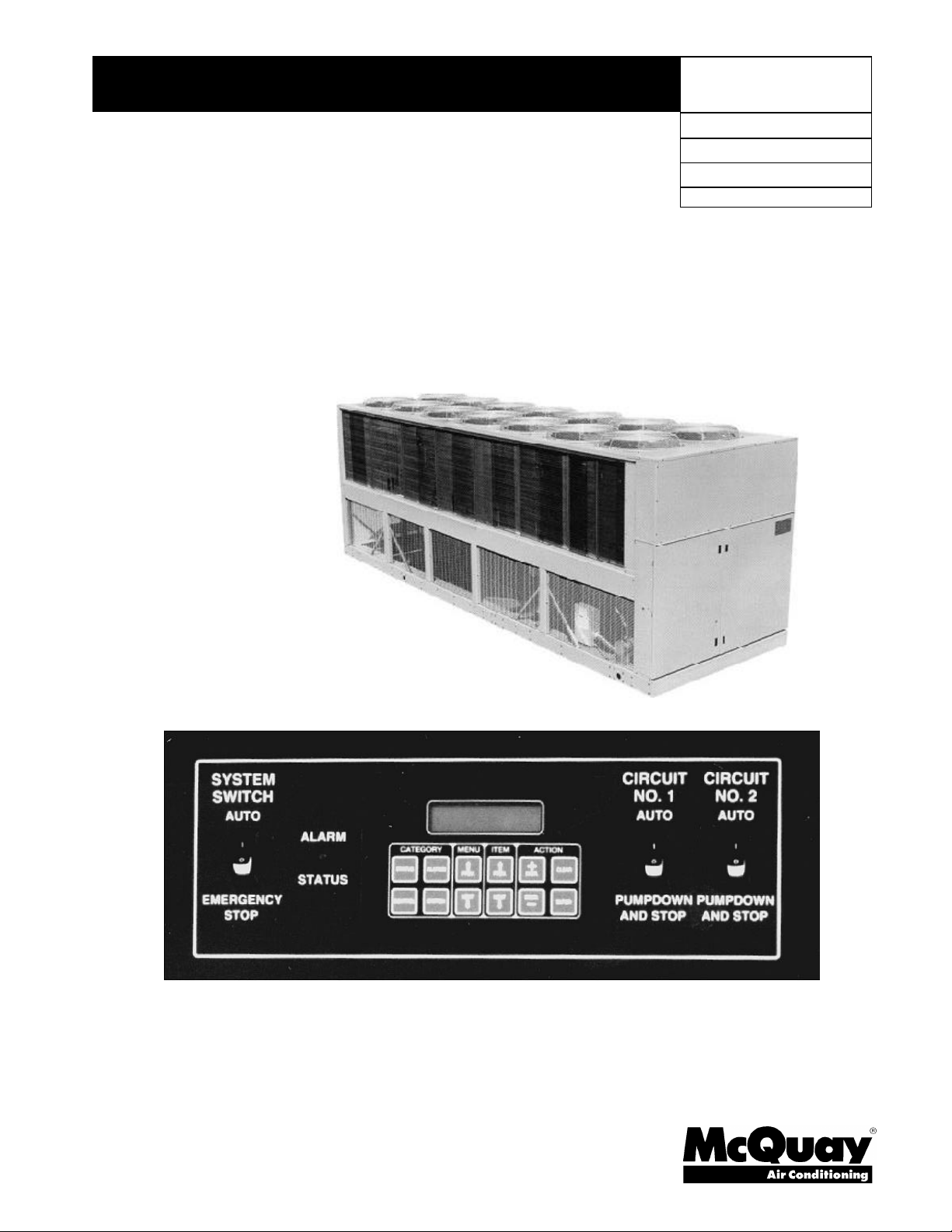
MicroTech Control System for Air-Cooled Screw Compressors
Models: ALS 125B through 425B
© 1999 McQuay International
Page 2

Table of Contents
Introduction.....................................3
General Description........................4
Control Panel Features...................4
Software Identification....................5
Controller Layout............................5
Component Data.............................6
Sensors and Transducers................8
Standard Sensors..........................................8
Optional Sensor Packages...........................8
Thermistor Sensors.......................................8
Pressure Transducers.................................10
Liquid Presence Sensor ..............................10
Sensor Data...................................11
Sensor Locations........................................11
Digital Inputs...............................................14
Optional Analog Outputs ..........................15
Digital Outputs............................................16
Installation.....................................18
Forced EXV Position Change...................25
EXV Evaporator Pressure Control...........25
Chilled Water Reset Options........26
Condenser Fan Control.................28
Condenser Fan Staging.............................28
Head Pressure Control ...............................28
Lift Pressure Dead Band............................29
Condenser Fan Stage Up ..........................29
High Pressure Stage Up ............................30
Condenser Fan Stage Down.....................30
SpeedTrol Logic .........................................30
Pumpdown......................................31
Safety Systems..............................32
ALS Unit – MicroTech Control Alarms...32
MicroTech Controller Test
Procedures.....................................36
Keypad/Display.............................37
MicroTech Component Test
Procedures.....................................38
Unit Sequence of Operation..........20
Compressor Control......................21
Compressor Staging Control
Sequence........................................22
Four Compressor Unit................................22
Three Compressors Unit............................22
Two Compressors Unit...............................22
Project-Ahead Calculation.........................23
Interstage Timer..........................................23
Anti-Cycle Timer.........................................23
Lead-Lag of Refrigerant Circuits.24
Electronic Expansion Valve..........24
Overview......................................................24
EXV Superheat Control..............................24
McQuay" is a registered trademark of McQuay International
"Illustrations and data cover the McQuay International products at the time of publication and we reserve the right to make changes in design
1997 McQuay International
and construction at anytime without notice"
Keypad Key Functions..................49
Personal Computer Specification.51
MicroTech Menu Structure..........52
Menus for Two (2) Screw
Compressor Units..........................53
Menus for Three (3) Screw
Compressor Units..........................61
Menus for Four (4) Screw
Compressor Units..........................68
Schematics and Drawings.............77
2 OM ALSMICRO
Page 3

Introduction
This manual provides installation, setup and troubleshooting information for the MicroTech controller
provided on McQuay air-cooled screw compressor chillers. Please refer to the current version of
installation manual IOMM ALS for unit application information as well as water and refrigerant piping
details. All operating descriptions contained in this manual are based on the current MicroTech
controller software version at time of publication. Contact McQuay Technical Response Center at 1877-349-7782 for information on specific code versions. Chiller operating characteristics and menu
selections may vary depending on the actual software version installed.
This equipment generates, uses and can radiate radio frequency energy and if not
installed and used in accordance with the instructions manual, may cause
interference to radio communications. It has been tested and found to comply with
the limits for a class A digital device, pursuant to part 15 of the FCC rules. These
limits are designed to provide reasonable protection against harmful interference
when the equipment is operated in a commercial environment.
Operation of this equipment in a residential area is likely to cause harmful
interference in which case the user will be required to correct the interference at his
own expense. McQuay International disclaims any liability resulting from any
interference or for the correction thereof.
CAUTION
CAUTION
The McQuay MicroTech control panel contains static sensitive components. A static
discharge while handling electronic circuit boards may cause damage to the
components.
To prevent such damage during service involving board replacement, McQuay
recommends discharging any static electrical charge by touching the bare metal
inside the panel before performing any service work.
CAUTION
Excessive moisture in the control panel can cause hazardous working conditions and
improper equipment operation.
When servicing equipment during rainy weather conditions, the electrical devices
and MicroTech components housed in the main control panel must be protected.
The MicroTech controller is designed to operate within an ambient temperature range of minus 40 to
plus 185°F and a maximum relative humidity of 95% (non-condensing).
OM ALSMICRO 3
Page 4
General Description
The MicroTech Unit Control Panel, available on all McQuay ALS products, contains a Model 250 or
280 Microprocessor based controller, which provides all monitoring, and control functions required
for the safe, efficient operation of the unit. The operator can monitor all operating conditions by
using the panel's built in 2 line by 16 character display and keypad or by using an IBM compatible
computer running McQuay Monitor software. In addition to providing all normal operating controls,
the MicroTech controller monitors all safety devices on the unit and will shut the system down and
close a set of alarm contacts if an alarm condition develops.
Important operating conditions at the time an alarm occurs are retained in the controller's memory to
aid in troubleshooting and fault analysis. The system is protected by a password scheme, which only
allows access, by authorized personnel. The operator must enter a valid password into the panel
keypad before any setpoints may be altered.
Table 1, Unit Identification
ALS Air-Cooled Chiller with Screw Compressors
Control Panel Features
Ø Flexible control of leaving chilled water with convenient reset capability.
Ø Enhanced head pressure control on air-cooled units resulting in increased total unit SEER.
Ø Convenient, easy to read 2 line by 16-character display for plain English readout of operating
temperatures and pressures, operating modes or alarm messages.
Ø Keypad adjustment of unit safeties such as low water temperature cutout, high pressure cutout,
suction pressure cutout, and freeze protection. The operator can use the keypad to monitor
various operating conditions, setpoints or alarm messages.
Ø Security password protection against unauthorized changing of setpoints and other control
parameters.
Ø Complete plain English diagnostics to inform the operator of system warnings and alarms. All
alarms are time and date stamped so there is no guessing of when the alarm condition occurred.
In addition, the operating conditions that existed at the instant of shutdown can be recalled to
aid in isolating the cause of the problem.
Ø Soft loading feature to reduce electrical consumption and peak demand charges during chilled
water loop pulldown.
Ø Easy integration into building automation systems via separate 4-20 milliamp signals for chilled
water reset and demand limiting. McQuay's Open Protocol feature is fully supported.
Ø Flexible internal time clock for on/off scheduling.
Ø Communications capabilities for local system monitoring, changing of setpoints, trend logging,
remote reset, alarm and event detection, via IBM compatible PC. The optional modem kit
supports the same features from an off-site PC running McQuay Monitor software.
Ø Special service modes may be used to override automatic unit staging during system checkout
and service.
Unit Identification
4 OM ALSMICRO
Page 5
Software Identification
Version
Software
Controller software is factory installed and tested in each panel prior to shipment. The software is
identified by a program code that is printed on a small label attached to the controller. The software
version may also be displayed on the keypad/display by viewing the last menu item in the Misc.
Setup menu.
The software "version" is the 6th & 7th location of the software number. In the example, the version
is "19" and the revision to the software is "A".
Revisions are released in alphabetical order.
Number of Compressors
Controller Layout
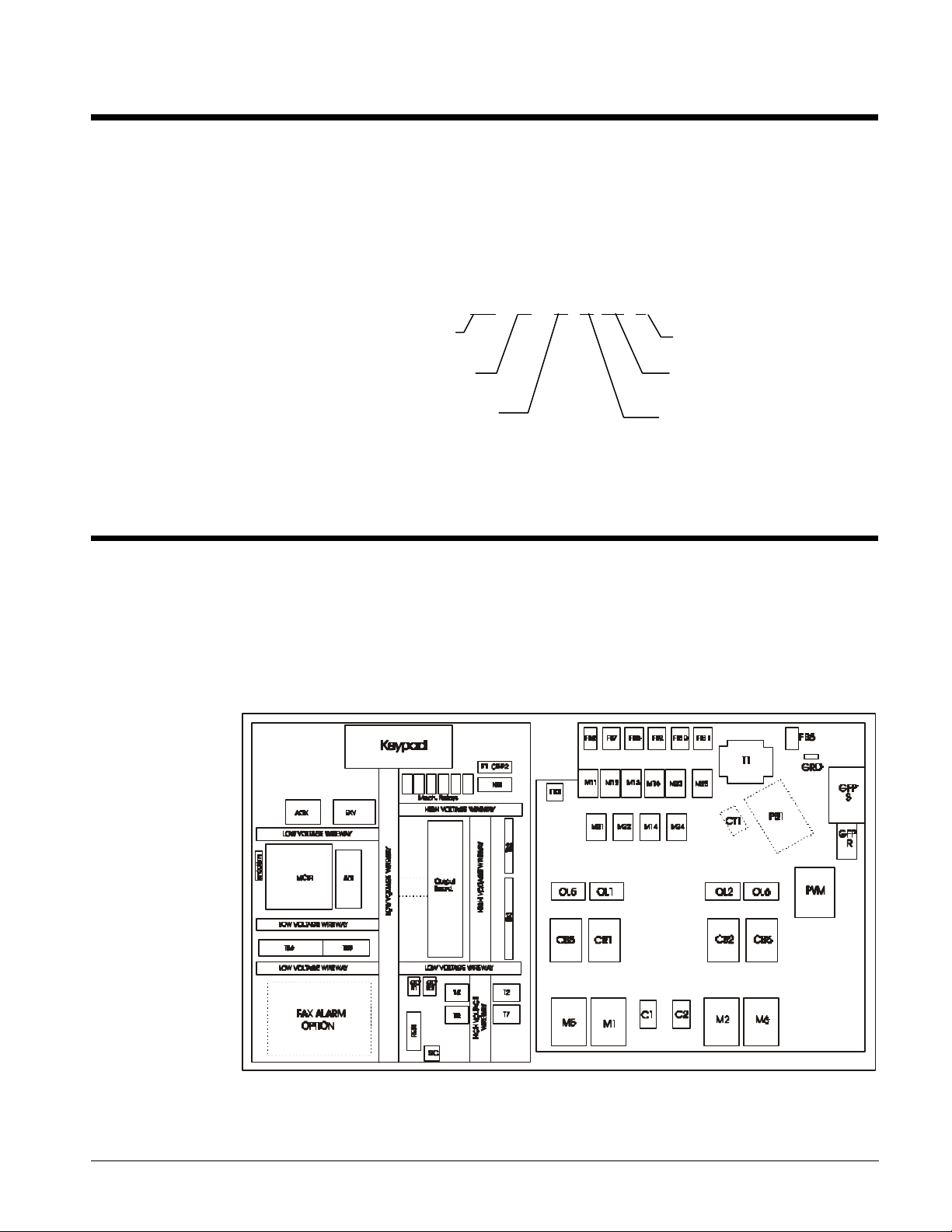
All major MicroTech components are mounted inside the control section side of the unit's control
cabinet. The individual components are interconnected by ribbon cables, shielded multi-conductor
cables, or discrete wiring. Transformers T-2 and T-4 provide power for the system. All field wiring
must enter the control cabinet through the knockouts provided and be terminated on field wiring
terminal strips. The standard ALS keypad/display is located inside the control cabinet for protection
from the weather. See Figure 1 for typical control cabinet layout.
Figure 1, Typical control cabinet layout
Hardware
Screw Chiller
Refrigerant
Type 2 = R22
Type 3 = R134a
SC 3 2 E 19 A
Revision
E = I-P
S = SI
OM ALSMICRO 5
Page 6
Component Data
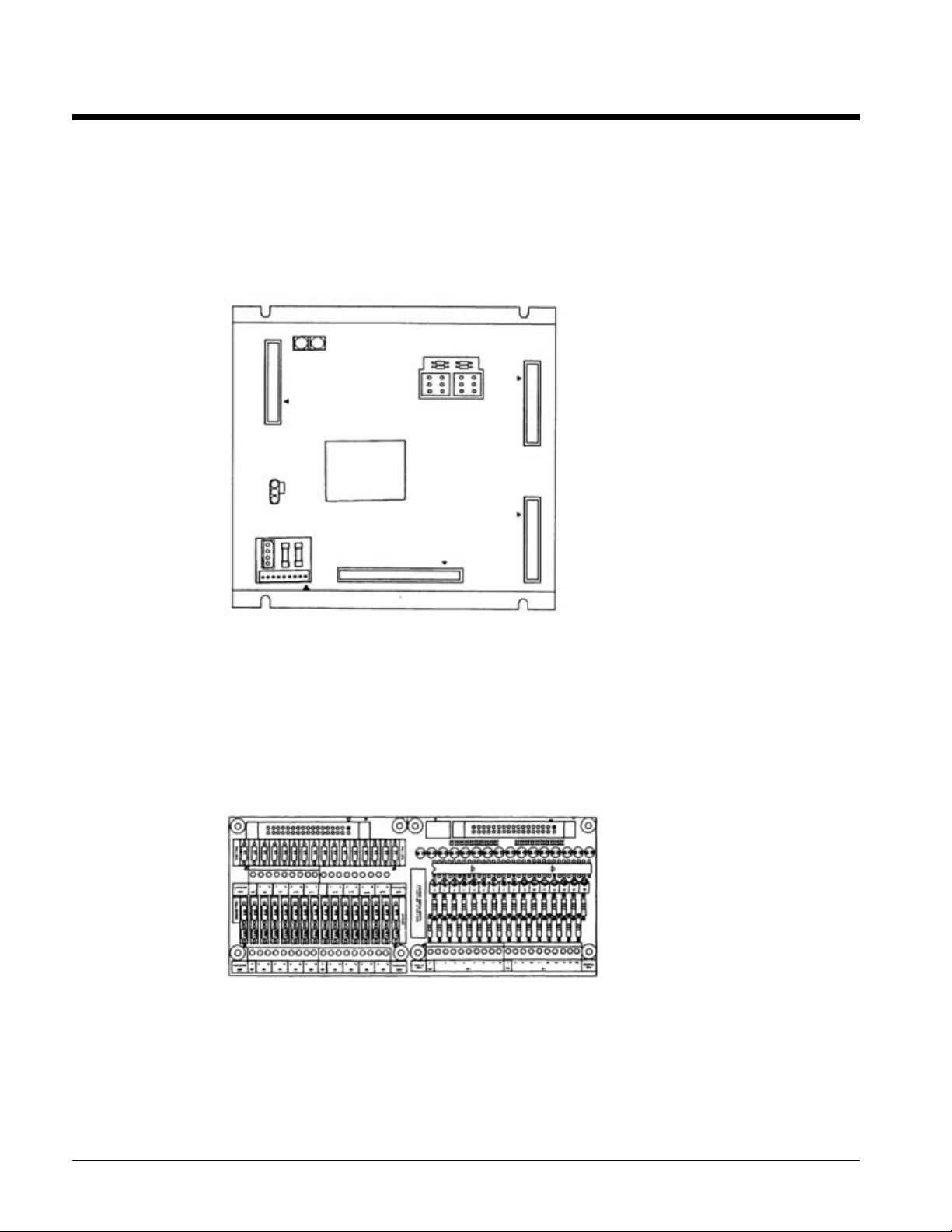
Microprocessor Control Board (MCB1)
The Model 250 or 280 Microprocessor Control Board contains the electronic hardware and software
required to monitor and control the unit. It receives input from the ADI Board and sends commands
to the Output Board to maintain the unit's optimum operating mode for the current conditions. Status
lights are mounted on the control board to indicate the operating condition of the microprocessor.
Figure 2, MCB1
Analog/Digital Input Board (ADI Board)
The ADI Board provides low voltage power for the temperature and pressure sensors. It also
provides electrical isolation between the Microprocessor Control Board and all 24V switch inputs.
LEDs are furnished on the board to give a visual indication of the status of all digital inputs. All
analog and digital signals from sensors, transducers and switches are received by the ADI Board and
then sent to the Microprocessor Control Board for interpretation.
Figure 3, ADI
Output Board
The Output Board contains up to 24 solid state relays, which are used to control all compressors,
condenser fans, solenoid valves and alarm annunciation.
It receives control signals from the Microprocessor Control Board through a 50-conductor ribbon
cable.
6 OM ALSMICRO
Page 7
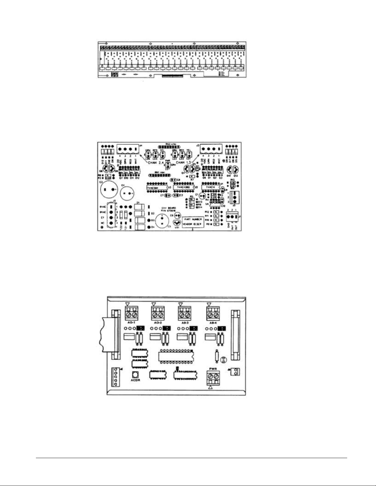
Figure 4, Output board
Electric Expansion Valve Board (EXV Board)
Each EXV Board will directly control up to two electronic expansion valves. The boards may be
cascaded together for units with more than two EXV's. Control instructions for the boards are
generated by the M250 controller.
Figure 5, EXV board
Analog Output Board (AOX Board) (With Optional SpeedTrol)
The AOX Board converts control instructions from the M250's expansion bus into an analog control
signal suitable for driving a variable speed condenser fan. Each AOX Board is factory set via jumper
to provide an output signal of 0 - 10 VDC.
Figure 6, AOX board
The Keypad/Display is the primary operator interface to the unit. All operating conditions, system
alarms and setpoints can be monitored from this display and all adjustable setpoints can be modified
from this keyboard if the operator has entered a valid operator password.
OM ALSMICRO 7
Page 8

Figure 7, Keypad display
Sensors and Transducers
Standard Sensors
Evaporator Leaving Water Temperature
Evaporator Refrigerant Pressure, Circuit #1, 2, 3 & 4
Condenser Refrigerant Pressure, Circuit #1, 2, 3 & 4
Suction Temperature, Circuit #1, 2, 3 & 4
Liquid Line Temperature, Circuit #1, 2, 3 & 4 (Provides direct display of subcooling and superheat)
Entering Evaporator Water Temperature
Outside Ambient Air Temperature
Optional Sensor Packages
Percent Unit Amps on 2 Compressor Units (Percent total unit amperage including compressors and
condenser fans. Does not include externally powered equipment such as water pumps.)
Percent Compressor Amps on 3 Compressor Units and Percent Circuit Amps (1 & 3, 2 & 4) on 4
Compressor Units.
Thermistor Sensors
MicroTech panels use a negative temperature coefficient thermistor for temperature sensing. A
normal sensor will measure 3000 ohms at 77°F.
Figure 8, Thermistor sensor
8 OM ALSMICRO
Page 9
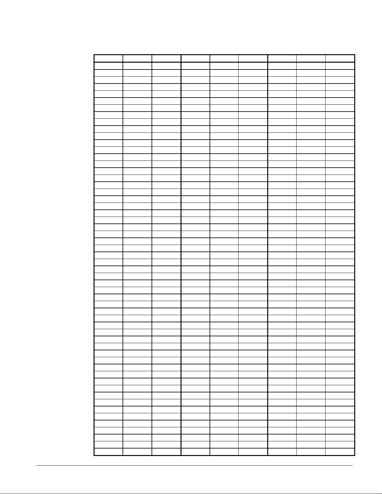
Table 2, MicroTech Thermistors
°F Ohms Volts °F Ohms Volts °F Ohms Volts
15 16,104 4.145 77 3,000 2.373 139 761 0.932
16 15,627 4.124 78 2,927 2.343 140 746 0.917
17 15,166 4.102 79 8,357 2.313 141 731 0.902
18 14,720 4.080 80 2,789 2.283 142 717 0.888
19 14,288 4.057 81 2,723 2.253 143 703 0.874
20 13,871 4.034 82 2,658 2.223 144 689 0.859
21 13,469 4.011 83 2,595 2.194 145 676 0.846
22 13,076 3.988 84 2,534 2.164 146 662 0.831
23 12,698 3.964 85 2,474 2.135 147 649 0.818
24 12,333 3.940 86 2,416 2.106 148 637 0.805
25 11,979 3.915 87 2,360 2.077 149 625 0.792
26 11,636 3.890 88 2,305 2.049 150 613 0.779
27 11,304 3.865 89 2,251 2.020 151 601 0.766
28 10,983 3.839 90 2,199 1.992 152 589 0.753
29 10,672 3.814 91 2,149 1.965 153 578 0.741
30 10,371 3.788 92 2,099 1.937 154 567 0.729
31 10,079 3.761 93 2,051 1.909 155 556 0.717
32 9,797 3.734 94 2,004 1.882 156 546 0.706
33 9,523 3.707 95 1,959 1.855 157 535 0.694
34 9,258 3.608 96 1,914 1.828 158 525 0.683
35 9,002 3.653 97 1,871 1.802 159 516 0.673
36 8,753 3.625 98 1,829 1.775 160 506 0.661
37 8,512 3.597 99 1,788 1.750 161 496 0.650
38 8,278 3.569 100 1,747 1.724 162 487 0.640
39 8,052 3.540 101 1,708 1.698 163 478 0.629
40 7,832 3.511 102 1,670 1.673 164 469 0.619
41 7,619 3.482 103 1,633 1.648 165 461 0.610
42 7,413 3.453 104 1,597 1.624 166 452 0.599
43 7,213 3.424 105 1,562 1.600 167 444 0.590
44 7,019 3.394 106 1,528 1.576 168 436 0.580
45 6,831 3.365 107 1,494 1.552 169 428 0.571
46 6,648 3.335 108 1,461 1.528 170 420 0.561
47 6,471 3.305 109 1,430 1.505 171 413 0.553
48 6,299 3.274 110 1,398 1.482 172 405 0.544
49 6,133 3.244 111 1,368 1.459 173 398 0.535
50 5,971 3.213 112 1,339 1.437 174 391 0.527
51 5,814 3.183 113 1,310 1.415 175 384 0.518
52 5,662 3.152 114 1,282 1.393 176 377 0.510
53 5,514 3.121 115 1,254 1.371 177 370 0.501
54 5,371 3.078 116 1,228 1.350 178 364 0.494
55 5,231 3.059 117 1,201 1.328 179 357 0.485
56 5,096 3.028 118 1,176 1.308 180 351 0.478
57 4,965 2.996 119 1,151 1.287 181 345 0.471
59 4,714 2.934 121 1,103 1.247 183 333 0.456
60 4,594 2.902 122 1,080 1.227 184 327 0.448
61 4,477 2.871 123 1,058 1.208 185 321 0.441
62 4,363 2.839 124 1,036 1.189 186 316 0.435
63 4,253 2.808 125 1,014 1.170 187 310 0.427
64 4,146 2.777 126 993 1.151 188 305 0.421
65 4,042 2.745 127 973 1.133 189 299 0.413
66 3,941 2.714 128 953 1.115 190 294 0.407
67 3,842 2.682 129 933 1.076 191 289 0.400
68 3,748 2.651 130 914 1.079 192 284 0.394
69 3,655 2.620 131 895 1.062 193 280 0.389
70 3,565 2.589 132 877 1.045 194 275 0.382
71 3,477 2.558 133 859 1.028 195 270 0.376
OM ALSMICRO 9
Page 10
72 3,392 2.527 134 842 1.012 196 266 0.371
73 3,309 2.496 135 825 0.995 197 261 0.364
74 3,328 2.465 136 809 0.980 198 257 0.359
75 3,150 2.434 137 792 0.963 199 252 0.353
76 3,074 2.404 138 777 0.948 200 248 0.348
Pressure Transducers
These transducers are selected for a specific operating range and provide an output signal, which is
proportional to the sensed pressure. The typical range for evaporator sensors is 0 to 150 psig with a
resolution of 0.1 psi. Condenser pressure sensors have a range of 0 to 450 psi and a resolution of 0.5
psi. The pressure transducers require an external 5 VDC power supply to operate that is provided by
the MicroTech controller. This connection should not be used to power any additional devices.
Figure 9, Pressure Transducer
Red Dot - Condenser
Blue Dot - Evaporator
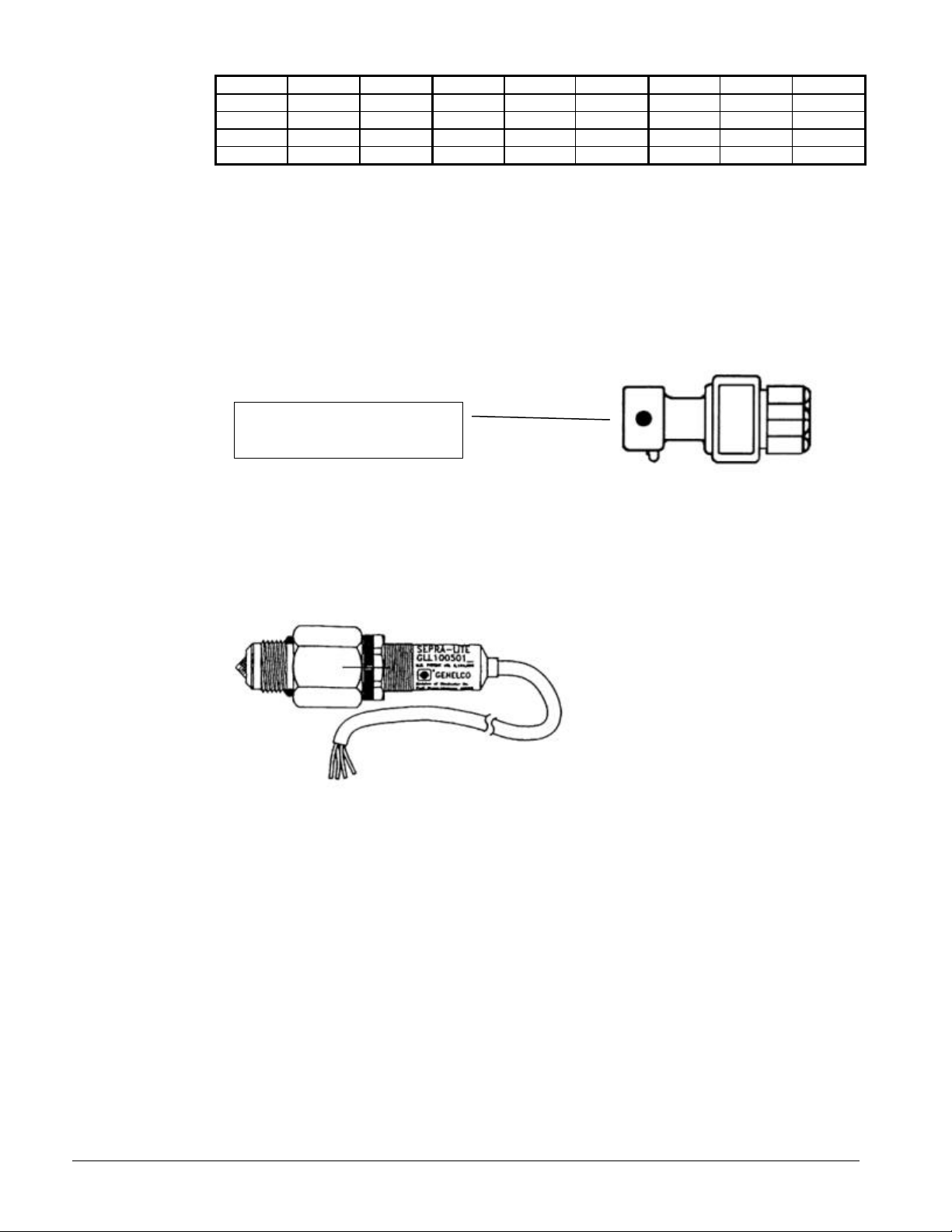
Liquid Presence Sensor
A liquid level sensor mounted at the liquid injection port in the compressor casting determines the
presence of liquid refrigerant. Whenever the glass prism sensor tip is in contact with liquid, the
sensor output signal will be high (>7 VDC). If no liquid is detected, the output will be low (O VDC).
Figure 10, Liquid Presence Sensor
10 OM ALSMICRO
Page 11
Sensor Data
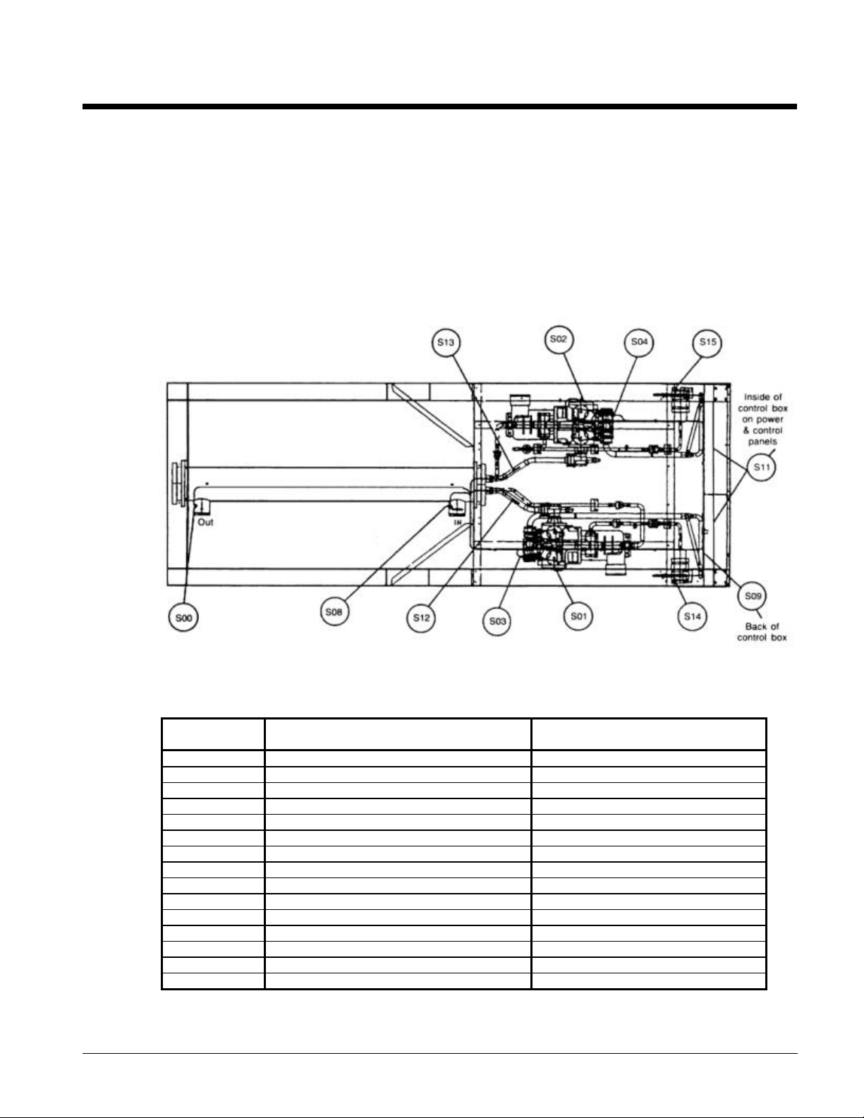
Sensor Locations
Analog Inputs
Analog inputs are used to read the various temperature and pressure sensors installed on the chiller as well
as any customer supplied 4-20mA reset signals. The controller's internal regulated 5 VDC and 12 VDC
supplies provide the correct operating voltage for the sensors.
Figure 11, Sensor Locations, Two Compressor Units
Table 3, Analog Inputs - 2 Compressor Units
Sensor
Number
S00 Evaporator Leaving Water Temperature Leaving Chilled Water Nozzle
S01 Evaporator Pressure Transducer Circuit #1 Common Circuit #1 Suction Line
S02 Evaporator Pressure Transducer Circuit #2 Common Circuit #2 Suction Line
S03 Condenser Pressure Transducer Circuit #1 Compressor #1 Discharge Cover
S04 Condenser Pressure Transducer Circuit #2 Compressor #2 Discharge Cover
Input05 Transducer Power Voltage Ratio (Internal)
Input06 Reset-Evaporator Water Temperature External 4-20 mA Signal
Input07 Demand Limit External 4-20 mA Signal
S08 Entering Evaporator Water Temperature Entering Chilled Water Nozzle
S09 O.A.T Back of the Control Box
S11 Percent Unit Amps CT1 and Signal Converter Board
S12 Suction Temperature Circuit #1 Well Brazed to the Circuit #1 Suction Line
S13 Suction Temperature Circuit #2 Well Brazed to the Circuit #2 Suction Line
S14 Liquid Line Temperature Circuit #1 Well Brazed to the Circuit #1 Liquid Line
S15 Liquid Line Temperature Circuit #2 Well Brazed to the Circuit #2 Liquid Line
OM ALSMICRO 11
Description Sensor Location
Page 12
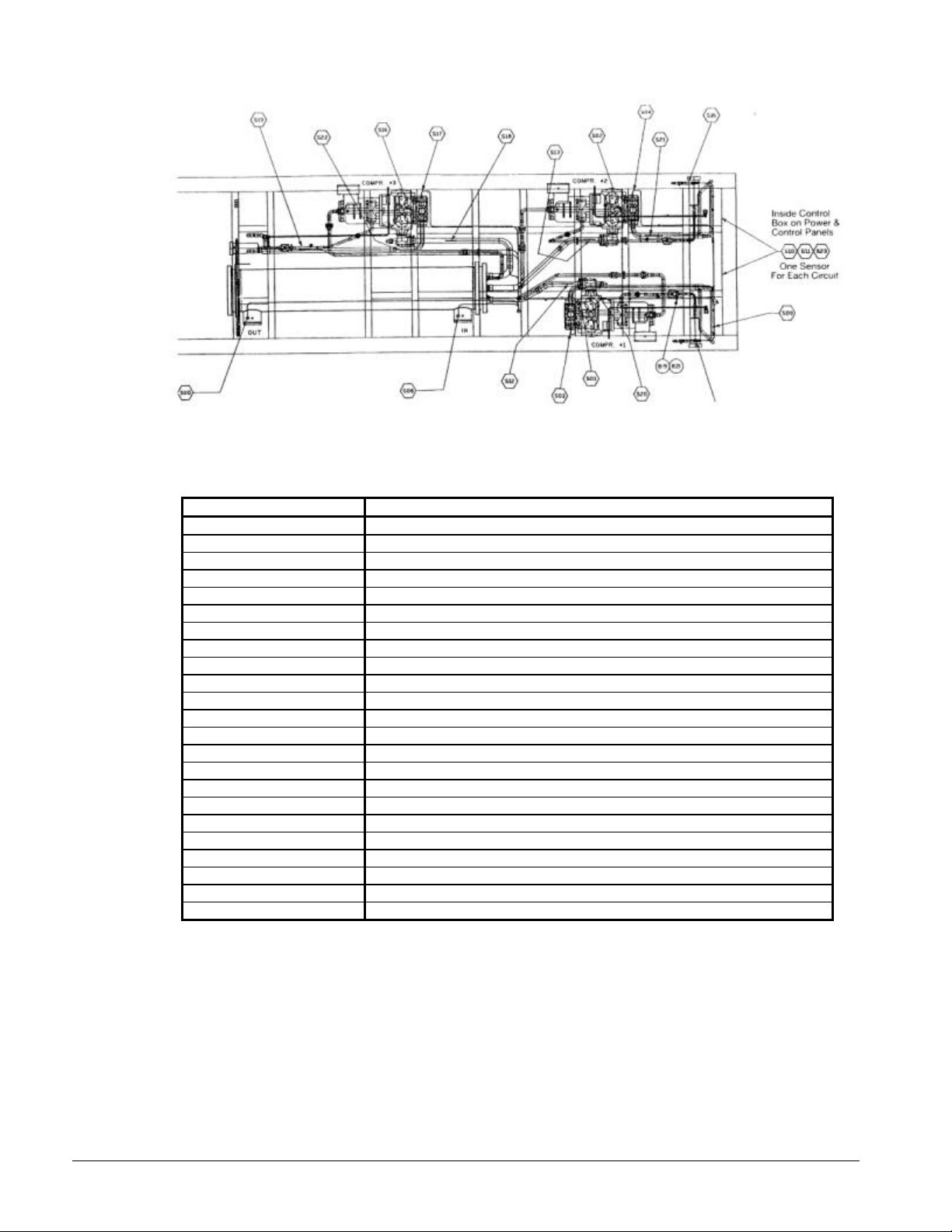
Figure 12, Sensor Locations - 3 Compressor Unit
Table 4, Analog Inputs - 3 Compressor Units
Sensor Number Description
S00 Evaporator Leaving Water Temperature
S01 Low Pressure Transducer Circuit #1
S02 Low Pressure Transducer Circuit #2
S03 High Pressure Transducer Circuit #1
S04 High Pressure Transducer Circuit #2
S06 Evaporator Water Temperature Reset (Field Supplied)
S07 Demand Limit (Field Supplied)
S08 Evaporator Entering Water Temperature
S09 Outside Air Temperature
S10 Percent Circuit Amps Circuit #1 (CT1)
S11 Percent Circuit Amps Circuit #2 (CT2)
S12 Suction Temperature Circuit #1
S13 Suction Temperature Circuit #2
S14 Liquid Line Temperature Circuit #1
S15 Liquid Line Temperature Circuit #2
S16 Low Pressure Transducer Circuit #3
S17 High Pressure Transducer Circuit #3
S18 Suction Temperature Circuit #3
S19 Liquid Line Temperature Circuit #3
S20 Discharge Temperature Circuit #1
S21 Discharge Temperature Circuit #2
S22 Discharge Temperature Circuit #3
S23 Percent Circuit Amps Circuit #3 (CT3)
12 OM ALSMICRO
Page 13
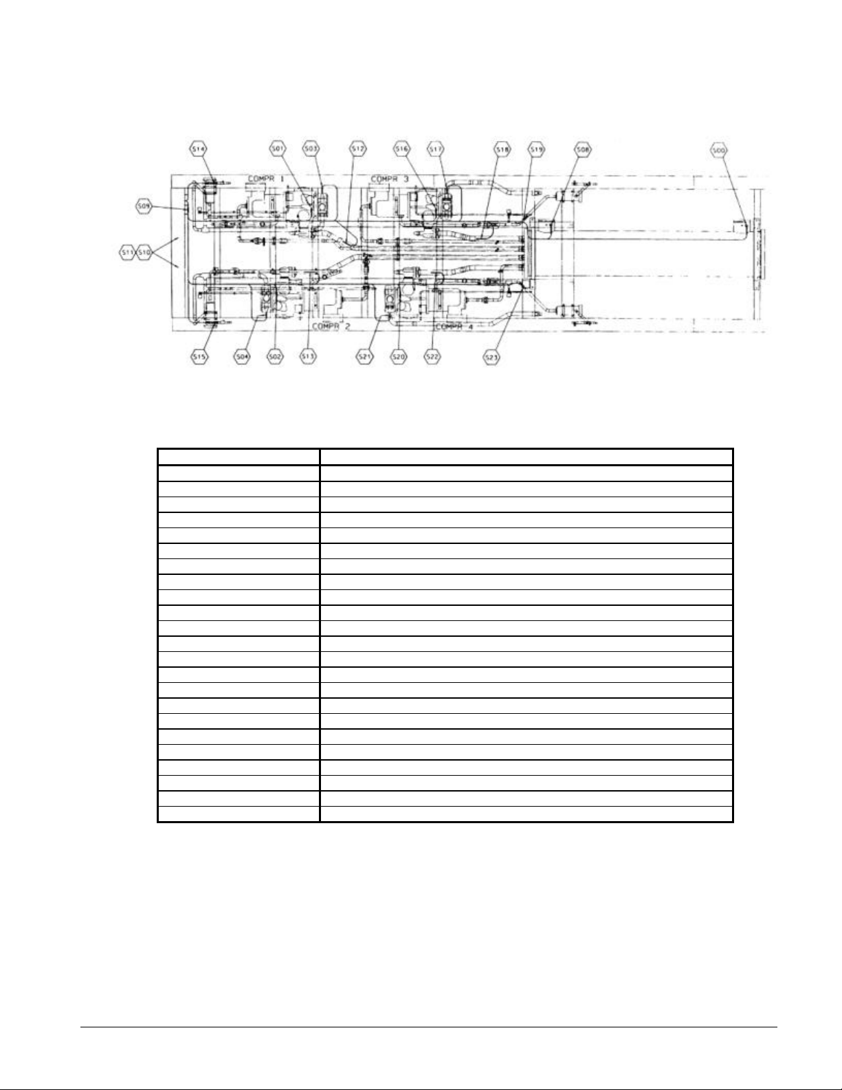
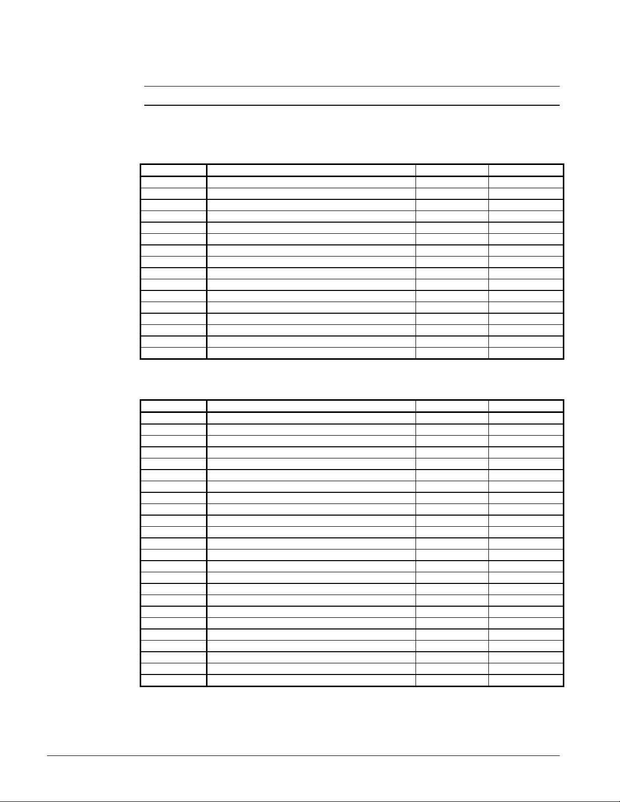
Figure 13, Sensor Locations - 4 Compressor Unit
Table 5, Analog Inputs - 4 Compressor Units
Sensor Number Description
S00 Evaporator Leaving Water Temperature
S01 Low Pressure Transducer Circuit #1
S02 Low Pressure Transducer Circuit #2
S03 High Pressure Transducer Circuit #1
S04 High Pressure Transducer Circuit #2
S06 Evaporator Water Temperature Reset (Field Supplied)
S07 Demand Limit (Field Supplied)
S08 Evaporator Entering Water Temperature
S09 Outside Air Temperature
S10 Percent Circuit Amps Circuit #1 & 3 (CT1)
S11 Percent Circuit Amps Circuit #2 & 4 (CT2)
S12 Suction Temperature Circuit #1
S13 Suction Temperature Circuit #2
S14 Liquid Line Temperature Circuit #1
S15 Liquid Line Temperature Circuit #2
S16 Low Pressure Transducer Circuit #3
S17 High Pressure Transducer Circuit #3
S18 Suction Temperature Circuit #3
S19 Liquid Line Temperature Circuit #3
S20 Low Pressure Transducer Circuit #4
S21 High Pressure Transducer Circuit #4
S22 Suction Temperature Circuit #4
S23 Liquid Line Temperature Circuit #4
OM ALSMICRO 13
Page 14
Digital Inputs
Note: All digital inputs are 24 VAC.
At 7.5 VAC to 24 VAC nominal the digital input contacts are considered closed, and the signal level is
high. Below 7.5 VAC nominal, the contacts are considered open, and the signal level is low.
Table 6, Digital Inputs - 2 Compressor Unit
Number Description Low Signal High Signal
0 Mechanical High Pressure Switch, Circuit #1 Alarm Normal
1 Liquid Presence Switch, Compressor #1 Alarm Normal
2 Motor Protect, Compressor #1 Alarm Normal
3 High Liquid Pressure Drop, #1 Alarm Normal
4 (Reserved) - -
5 System Switch (S1) Stop Run
6 Phase Voltage Monitor Alarm Normal
7 Pump Down Switch, Circuit #1 Normal Pumpdown
8 Mechanical High Pressure Switch, Circuit #2 Alarm Normal
9 Liquid Presence Switch, Compressor #2 Alarm Normal
10 Motor Protect, Compressor #2 Alarm Normal
11 High Liquid Pressure Drop, # 2 Alarm Normal
12 (Reserved) - -
13 Unit Remote Stop Switch Stop Run
14 Evap Water Flow Switch Alarm Normal
15 Pump Down Switch, Circuit #2 Normal Pumpdown
Table 7, Digital Inputs - 3 Compressor Unit
Number Description Led On Led Off
0 Mechanical High Pressure Switch, Circuit #1 Alarm Normal
1 Liquid Presence Sensor Compressor #1 No Liquid Liquid
2 Motor Protect, Compressor #1 Alarm Normal
3 High Liquid Pressure Drop, #1 Alarm Normal
4 Not Used - -
5 System On/Off Switch Off On
6 Phase Voltage Monitor Compressor #1 Alarm Normal
7 PumpDown Switch Compressor #1 Normal Pumpdown
8 Mechanical High Pressure Switch, Circuit #2 Alarm Normal
9 Liquid Presence Sensor Compressor #2 No Liquid Liquid
10 Motor Protect, Compressor #2 Alarm Normal
11 High Liquid Pressure Drop, #2 Alarm Normal
12 Not Used - -
13 Remote Start Stop Switch Stop Start
14 Evap Water Flow Switch No Flow Flow
15 PumpDown Switch, Circuit #2 Normal Pumpdown
16 Mechanical High Pressure Switch Circuit #3 Alarm Normal
17 Liquid Presence Sensor Compressor #3 No Liquid Liquid
18 Motor Prot Compressor #3 Alarm Normal
19 High Liquid Pressure Drop, #3 Alarm Normal
20 Not Used - -
21 Phase Volt Monitor Compressor #2 Alarm Normal
22 Phase Volt Monitor Compressor #3 Alarm Normal
23 PumpDown Switch Compressor #3 Alarm Normal
14 OM ALSMICRO
Page 15
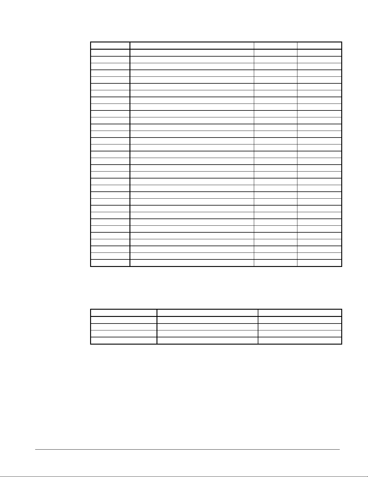
Table 8, Digital Inputs - 4 Compressor Unit
Number Description Led On Led Off
0 Mechanical High Pressure Switch, Circuit #1 Alarm Normal
1 Liquid Presence Sensor Compressor #1 No Liquid Liquid
2 Motor Protect, Compressor #1 Alarm Normal
3 High Liquid Pressure Drop, #1 Alarm Normal
4 Not Used - -
5 System On/Off Switch Off On
6 Phase Voltage Monitor Compressor #1 Alarm Normal
7 PumpDown Switch Compressor #1 Normal Pumpdown
8 Mechanical High Pressure Switch, Circuit #2 Alarm Normal
9 Liquid Presence Sensor Compressor #2 No Liquid Liquid
10 Motor Protect, Compressor #2 Alarm Normal
11 High Liquid Pressure Drop, #2 Alarm Normal
12 Not Used - -
13 Remote Start Stop Switch Stop Start
14 Evap Water Flow Switch No Flow Flow
15 PumpDown Switch, Circuit #2 Normal Pumpdown
16 Mechanical High Pressure Switch Circuit #3 Alarm Normal
17 Liquid Presence Sensor Compressor #3 No Liquid Liquid
18 Motor Prot Compressor #3 Alarm Normal
19 High Liquid Pressure Drop, #3 Alarm Normal
20 Not Used - -
21 Phase Volt Monitor Multi Point Alarm Normal
22 Not Used - -
23 Pumpdown Switch compressor #3 Normal Pumpdown
0 Mechanical High Pressure Switch Circuit #4 Alarm Normal
1 Liquid Presence Sensor Compressor #4 No Liquid Liquid
2 Motor Prot Compressor #4 Alarm Normal
3 High Liquid Pressure Drop, #4 Alarm Normal
4 Not Used - -
5 Not Used - -
6 Not Used - -
7 Pumpdown Switch Compressor #4 Normal Pumpdown
Optional Analog Outputs
Table 9, Analog Outputs
Number Description Signal Range
0 SpeedTrol, Circuit #1 0-10 VDC
1 SpeedTrol, Circuit #2 0-10 VDC
2 SpeedTrol, Circuit #3 0-10 VDC
3 SpeedTrol, Circuit #4 0-10 VDC
OM ALSMICRO 15
Page 16

Digital Outputs
Table 10, Digital Outputs - 2 Compressor Unit
Relay Description Off On
0 Alarm LED and Contact (Programmable) (Programmable)
1 Chilled Water Pump Stop Run
2 EXV Serial Data 1
3 EXV Serial Data 2
4 MCR Relay. Compressor#1 Stop Run
5 Top Solenoid, Compressor #1 Hold Load
6 Bottom Right Solenoid, Compressor #1 Hold Load
7 Bottom Left Solenoid, Compressor #1 Hold Load
8 MCR Relay, Compressor #2 Stop Run
9 Top Solenoid, Compressor #2 Hold Load
10 Bottom Right Solenoid, Compressor #2 Hold Unload
11 Bottom Left Solenoid, Compressor #2 Hold Load
12 Condenser Fan #1, Circuit #1 (M12) Off On
13 Condenser Fan #2, Circuit #1 (M13) Off On
14 Condenser Fan #3, Circuit #1 (M14) Off On
15 Condenser Fan #4, Circuit #1 (M15) Off On
16 Condenser Fan #1, Circuit #2 (M22) Off On
17 Condenser Fan #2, Circuit #2 (M23) Off On
18 Condenser Fan #3, Circuit #2 (M24) Off On
19 Condenser Fan #4, Circuit #2 (M25) Off On
20 Liquid Solenoid Valve, Circuit #1 Close Open
21 Liquid Solenoid Valve, Circuit #2 Close Open
22 (Spare)
23 (Spare)
Table 11, Digital Outputs - 3 Compressor Unit
Relay Description
0 Alarm Circuit
1 Chilled Water Pump Relay
2 EXV Control
3 EXV Control
4 Compressor #1 Contactor
5 Compressor #1 Top Solenoid Valve
6 Compressor #1 Bottom Right Solenoid Valve (feed)
7 Compressor #1 Bottom Left Solenoid Valve (vent)
8 Compressor #2 Contactor
9 Compressor #2 Top Solenoid Valve (feed)
10 Compressor #2 Bottom Right Solenoid Valve (feed)
11 Compressor #2 Bottom Left Solenoid Valve (vent)
12 Condenser Fan Contactor M-12
13 Condenser Fan Contactor M-13
14 Condenser Fan Contactor M-14
15 Condenser Fan Contactor M-15
16 Condenser Fan Contactor M-22
17 Condenser Fan Contactor M-23
18 Condenser Fan Contactor M-24
19 Condenser Fan Contactor M-25
20 Compressor #3 Contactor
21 Compressor #3 Top Solenoid Valve (feed)
22 Compressor #3 Bottom Right Solenoid Valve (feed)
23 Compressor #3 Bottom Left Solenoid Valve (vent)
24 Condenser Fan Contactor M-32
25 Condenser Fan Contactor M-33
16 OM ALSMICRO
Page 17
26 Condenser Fan Contactor M-34
27 Condenser Fan Contactor M-34
28 Optional Hot Gas Bypass - SV5
29 Optional Hot Gas Bypass - SV6
Table 12, Digital Outputs - 4 Compressor Unit
Relay Description
0 Alarm Circuit
1 Chilled Water Pump Relay
2 EXV Control
3 EXV Control
4 Compressor #1 Contactor
5 Compressor #1 Top Solenoid Valve
6 Compressor #1 Bottom Right Solenoid Valve (feed)
7 Compressor #1 Bottom Left Solenoid Valve (vent)
8 Compressor #2 Contactor
9 Compressor #2 Top Solenoid Valve (feed)
10 Compressor #2 Bottom Right Solenoid Valve (feed)
11 Compressor #2 Bottom Left Solenoid Valve (vent)
12 Condenser Fan Contactor M-12
13 Condenser Fan Contactor M-13
14 Condenser Fan Contactor M-14
15 Condenser Fan Contactor M-15
16 Condenser Fan Contactor M-22
17 Condenser Fan Contactor M-23
18 Condenser Fan Contactor M-24
19 Condenser Fan Contactor M-25
20 Compressor #3 Contactor
21 Compressor #3 Top Solenoid Valve (feed)
22 Compressor #3 Bottom Right Solenoid Valve (feed)
23 Compressor #3 Bottom Left Solenoid Valve (vent)
24 Condenser Fan Contactor M-32
25 Condenser Fan Contactor M-33
26 Condenser Fan Contactor M-34
27 Condenser Fan Contactor M-35
28 Optional Hot Gas Bypass - SV5
29 Optional Hot Gas Bypass - SV6
30 Not Used
31 Compressor #4 Contactor
32 Compressor #4 Top Solenoid Valve (feed)
33 Compressor #4 Bottom Right Solenoid Valve (feed)
34 Compressor #4 Bottom Left Solenoid Valve (vent)
35 Condenser Fan Contactor M-42
36 Condenser Fan Contactor M-43
37 Condenser Fan Contactor M-44
38 Condenser Fan Contactor M-45
OM ALSMICRO 17
Page 18

Installation
Controller Calibration
The control software is installed and tested by the factory prior to shipping therefore no periodic
calibration of the controller is required. All control and safety setpoints will be checked and adjusted
if necessary by the McQuayService start-up technician prior to starting the unit. The MicroTech
controller contains default setpoints that will be appropriate for most common installations.
Field Wiring
Analog sensors and transducers
All sensors and transducers required for normal chiller operation are installed and wired by the
factory. Any optional analog signals provided by the installing contractor require twisted, shielded
pair wire (Belden #8760 or equal).
Digital input signals
Remote contacts for all digital inputs such as the chilled water flow switch and the remote start/stop
switch must be dry contacts suitable for the 24 VAC control signals produced by the screw chiller
panel.
Digital outputs
Devices wired to the digital outputs typically are an optional Chilled Water Pump control relay or an
Alarm Annunciator. The MicroTech output device is a normally open solid state relay with an on
board, replaceable 5 amp fuse. The model 250 controller activates a solid state relay by sending a
"trigger" signal to the output board via the attached ribbon cable. The relay responds to the trigger
by lowering its resistance that allows current to flow through its "contacts". When the controller
removes the trigger signal, the relay's resistance becomes very high, causing the current flow to stop.
The status of all outputs is shown by individual red LEDs for ease of determining output status.
Interlock wiring
The installing contractor provides all interlock wiring to field devices such as flow switches and pump
starters. Refer to the Field Wiring Drawing as well as the unit wiring schematics and typical
application drawings at the end of this manual for details.
External alarm circuit
The MicroTech panel can activate an external alarm circuit when an alarm or pre-alarm condition is
detected. A 24 VAC voltage source is available at field wiring terminals #102 through #107 to power
an external alarm device such as a bell, light or relay. An alarm annunciator rated for a maximum load
of 1.8 Amps at 24 VAC is to be provided and wired by the installing contractor. The normal and alarm
states for the 24 VAC alarm signal are programmable by the operator. Available settings are:
Ø Pre-alarm annunciation: Close-or-Open-or-Blink
Ø Alarm annunciation: Close-or-Open
Power wiring
115 VAC power for the control transformer is derived from the 3-phase power connection provided by
the electrical contractor.
A separate disconnect for the cooler heating tape and control circuit transformer may be supplied as
options on some installations. Wiring for these circuits is to be provided by the installing contractor
and should conform to the National Electrical Code and all applicable local building codes.
Power supplies
There are several internal power supplies used by the controller and its associated circuitry. The
regulated 5 VDC power on terminal #42 is used to support the analog inputs on the ADI Board and
18 OM ALSMICRO
Page 19

should not be used to operate any external devices. An unregulated 12 VDC power supply is
available on field wiring terminal #56 and an unregulated 24 VAC supply is provided at terminal #81.
Both of these may be used for powering external devices such as low current relays and lights.
Demand limit and chilled water reset signals
Separate 4-20 milliamp signals for remote chilled water reset and demand limit can be provided by the
customer and should be connected to the appropriate terminals on the field wiring strip inside the
control cabinet. The optional demand limit and chilled water reset signals are 4 to 20 milliamp DC
signals. The resistive load used to condition the milliamp input signals is a 249 ohm resistor factory
mounted on the ADI Board.
Communication ports
Communication port "A" is provided on the MicroTech controller for connection to an IBM
compatible computer for local or remote system monitoring (Belden 8762 or equivalent). The network
uses the RS232 communication standard with a maximum cable length of 50 feet. All communication
network wiring utilizes low voltage shielded twisted pair cable. See the Personal Computer
Specification section of this manual for specific hardware requirements.
Communication port "B" is used to link the unit controller into a MicroTech network using the RS485
communication standard. Refer to the field wiring in this manual for details.
Modem Kit
An optional modem kit may be installed for remote monitoring of the chiller from an off-site PC
running McQuay's Monitor software. The kit comes complete with modem, wiring harness and
installation instructions.
Remote monitoring of the MicroTech controller requires a dedicated telephone line supplied by the
equipment owner. The McQuay Monitor software package used to establish a remote connection to
the modem kit must be purchased separately.
Telephone line for remote modem access
A voice quality, direct dial telephone line is required if remote access and monitoring of the unit
controller is desired. The phone line should be terminated with a standard RJ-11 modular phone plug.
OM ALSMICRO 19
Page 20

Unit Sequence of Operation
The following sequence of operation is typical for McQuay ALS air-cooled chillers. The sequence
may vary depending on various options that may be installed on the chiller.
Off Conditions
With power supplied to the unit, 115 VAC power is applied through the control fuse F1 to the
compressor casing heaters, the compressor motor protector circuits, the primary of the 24V control
circuit transformer and optionally, the evaporator heater (HTR5). The 24V transformer provides power
to the MicroTech controller and related components. With 24V power applied, the controller will
check the position of the front panel System Switch (S 1). If the switch is in the "stop, position the
chiller will remain off and the display will indicate the operating mode to be OFF:SystemSw. The
controller will then check the PumpDown Switches. If any switch is in the "stop" position, that
circuit's operating mode will be displayed as OFF:RemoteComm if this operating mode is in effect. If
an alarm condition exists which prevents normal operation of both refrigerant circuits, the chiller will
be disabled and the display will indicate OFF:AllCompAlarm.
The MicroTech controller allows the operator to manually set the chiller to an off mode via the
keypad. The display indicates this operating mode with the message OFF:ManualMode.
Assuming none of the above "Off" conditions are true, the controller will examine the internal time
schedule to determine if the chiller should start. The operating mode will be OFF:TimeClock if the time
schedule indicates an "off"' time period.
Start-up
If none of the above "Off" conditions are true, the MicroTech controller will initiate a start sequence
and energize the chilled water pump output relay. The display will indicate Starting as the operating
mode. The chiller will remain in the Waiting For Flow mode until the field installed flow switch
indicates the presence of chilled water flow. If flow is not proven within 30 seconds, the alarm output
will be activated and the chiller will continue to wait for proof of chilled water flow. When chilled
water flow is re-established, the alarm will be automatically cleared.
Waiting for Load
Once flow is established the controller will sample the chilled water temperature and compare it
against the Leaving Chilled Water Setpoint, the Control Band and the Load Delay which have been
programmed into the controller's memory. If the leaving chilled water temperature is above the
Leaving Chilled Water Setpoint plus ½ the adjustable Control Band plus the Start-up Delta Temperature
Setpoint, the controller will start the lead compressor.
Start Requested
In the Start Requested Mode, the electronic expansion valve is fully closed. The MicroTech controller
will read the evaporator pressure to ensure that at least 4 psi of refrigerant pressure is present. If the
evaporator pressure is less than 4 psi the compressor will not be enabled and the display will read
"NoStart-LoEvap".
Prepurge
In order to purge the compressor of any liquid refrigerant that may be present, the starting compressor
is operated at 50% capacity while the electronic expansion valve is held fully closed. The refrigerant
circuit will continue to run in this mode until either the evaporator refrigerant pressure drops to less
than 40 psi or 60 seconds has elapsed. If the evaporator pressure does not drop to 40 psi within the
60 seconds, the compressor will continue to run and the display will read "Failed Prepurge". The
alarm is logged in the alarm buffer.
20 OM ALSMICRO
Page 21

Opened EXV
With the evaporator pressure less than 40 psi and the compressor still running, the electronic
expansion valve will be driven open to 300 steps. If the evaporator pressure rises above the freezestat setpoint, the chiller will advance to Cool Staging Mode. If the circuit is in Cool Staging Mode and
after 20 seconds, the evaporator pressure remains below the freeze state setpoint but is greater than 2
psi, the controller will transition to Low Ambient Start Mode.
Low Ambient Start
If the difference between the freeze stat setpoint and the evaporator refrigerant pressure is greater
than 12 psi, the low ambient start timer will be set to l80 seconds. The compressor will continue to run
for 180 seconds from the moment the expansion valve is opened in an attempt to build up the
evaporator pressure. If the difference between the freeze stat setpoint and the evaporator refrigerant
pressure is greater than 12 psi, the following calculation will be used to set the low ambient start timer:
Low Ambient timer = 360 - (Pressure Difference X 15)
If the calculated low ambient timer value is greater than 360, the compressor will be stopped, the alarm
output will be activated and the display will indicate "FailLowAmbStart".
Cool Stage
Circuit capacity at initial start will be 50%. Once the chiller has started, the MicroTech controller will
add or subtract cooling capacity to maintain the chilled water setpoint. The current cooling stage will
be displayed on the keypad/display. Automatic chiller staging may be overridden by selecting
"Manual Cooling" as the operating mode and then choosing the desired cooling stage.
"Manual Cooling" will by-pass all interstage timers. This will result in rapid
compressor stage up and possible chilled water temperature overshoot. The unit will
not unload as the chillers water temperature reaches the setpoint.
Compressor Control
Normal Compressor Staging Logic
The Compressor Staging Logic uses an adjustable control band and interstage timers to determine the
correct number of cooling stages to activate. A project-ahead temperature calculation provides stable
operation. The total number of cooling stages for each circuit is dependent upon the "number of
cooling stages" setpoint.
Operation at 25% is not allowed on compressors #3 and #4.
For compressors #1 and 2, 25% is selectable by setting MinStage = 1. Then 30 minutes is the
maximum timer setting allowed at 25%. If the evaporator Delta-T is less than 1 degree F. then 5
minutes at 25% load is allowed.
Operation at 25% load is not allowed if the outside ambient air temperature is below the minimum
setpoint of 60°F.
CAUTION
OM ALSMICRO 21
Page 22
Compressor Staging Control Sequence
Four Compressor Unit
Staging Up Staging Down
Stage
10 75% 75% 50% 50% 62.5% 75% 75% 50% 50% 62.5%
11 75% 75% 75% 50% 68.8% 75% 75% 75% 50% 68.8%
12 75% 75% 75% 75% 75.0% 75% 75% 75% 75% 75.0%
13 100% 75% 75% 75% 81.3% 100% 75% 75% 75% 81.3%
14 100% 100% 75% 75% 87.5% 100% 100% 75% 75% 87.5%
15 100% 100% 100% 75% 93.8% 100% 100% 100% 75% 93.8%
16 100% 100% 100% 100% 100.0% 100% 100% 100% 100% 100.0%
Lead
Comp.
1 - - - - 0.0% 25% 0% 0% 0% 6.3%
2 50% 0% 0% 0% 12.5% 50% 0% 0% 0% 12.5%
3 75% 0% 0% 0% 18.8% 75% 0% 0% 0% 18.8%
4 50% 50% 0% 0% 25.0% 50% 50% 0% 0% 25.0%
5 75% 50% 0% 0% 31.3% 75% 50% 0% 0% 31.3%
6 75% 75% 0% 0% 37.5% 50% 50% 50% 0% 37.5%
7 75% 50% 50% 0% 43.8% 75% 50% 50% 0% 43.8%
8 75% 75% 50% 0% 50.0% 50% 50% 50% 50% 50.0%
9 75% 75% 75% 0% 56.3% 75% 75% 50% 50% 56.3%
Lag 1
Comp.
Lag 2
Comp.
Lag 3
Comp.
Unit
Capacity
Lead
Comp
Lag 1
Comp.
.
Lag 2
Comp.
Lag 3
Comp.
Unit
Capacity
Three Compressors Unit
Staging Up Staging Down
Stage
10 100% 75% 75% 83.3 100% 75% 75% 83.3
11 100% 100% 75% 91.7 100% 100% 75% 91.7
12 100% 100% 100% 100.0 100% 100% 100% 100.0
Lead
Comp.
1 - - - 0.0 25% 0% 0% 8.3
2 50% 0% 0% 16.7 50% 0% 0% 16.7
3 75% 0% 0% 25.0 75% 0% 0% 25.0
4 50% 50% 0% 33.3 50% 50% 0% 33.3
5 75% 50% 0% 41.7 75% 50% 0% 41.7
6 75% 75% 0% 50.0 50% 50% 50% 50.0
7 75% 50% 50% 58.3 75% 50% 50% 58.3
8 75% 75% 50% 66.6 75% 75% 50% 66.6
9 75% 75% 75% 75.0 75% 75% 75% 75.0
Lag 1
Comp.
Lag 2
Comp.
Unit
Capacity
Lead
Comp.
Lag 1
Comp.
Lag 2
Comp.
Capacity
Two Compressors Unit
Staging Up Staging Down
Stage
Lead
Comp.
1 - - 0.0 25% 0% 12.5
2 50% 0% 25.0 50% 0% 25.0
3 75% 0% 37.5 75% 0% 37.5
4 50% 50% 50.0 50% 50% 50.0
5 75% 50% 62.5 75% 50% 62.5
6 75% 75% 75.0 75% 75% 75.0
Lag 1
Comp.
Unit
Capacit
y
Lead
Comp.
Lag 1
Comp.
Unit
Capacity
Unit
22 OM ALSMICRO
Page 23

7 100% 75% 87.5 100% 75% 87.5
8 100% 100% 100.0 100% 100% 100.0
Project-Ahead Calculation
The Project-Ahead Calculation provides protection against an overshoot condition when the chilled
water temperature is outside the control band. During cooling mode, if the Chilled Water Temperature
is above the control band and the rate of temperature reduction is so great that in 120 seconds the
chilled water temperature will be below the control band, the controller will stage down. The ProjectAhead Calculation also moderates the controller's response to a rapid increase in leaving water
temperature.
Interstage Timer
The minimum time delay between stage up commands is set by the interstage timer setpoint
(default=120 sec). The interstage timer for stage down commands is 1/5 of the stage up timer.
Anti-Cycle Timer
Anti-cycle timers are used to protect the compressors from excessive starts and high motor winding
temperature. The anti-cycle timers are 5 minutes stop-to-start and 15 minutes start-to-start.
OM ALSMICRO 23
Page 24

Lead-Lag of Refrigerant Circuits
The following compressor control rules are enforced in the control software.
Ø The MicroTech controller will never turn on the lag compressor until the lead compressor is at
75% capacity or greater and additional cooling capacity is required.
Ø The MicroTech controller will not turn off the lag compressor until the lead compressor is
running at 50% capacity, the lag compressor is running at 25% capacity and a reduction in
cooling capacity is required. Three and four compressor units lag at 50% before pumpdown.
Automatic Lead-Lag
The controller provides automatic lead-lag of refrigeration circuits based on compressor operating
hours and the number of starts. The circuit with the fewest number of starts will be started first. If
circuits are operating and a stage down is required, the circuit with the most operating hours will cycle
off first.
Manual Lead-Lag
The operator may override automatic circuit selection by manually selecting the lead circuit via the
keypad or monitor.
When the setpoint equals "auto", the lead compressor is selected by the MicroTech controller based
upon which circuit has the least operating hours. Regardless of the mode selected, if the lead circuit
cannot operate due to an alarm condition or if off on cycle timers, the controller will switch to the lag
circuit.
Electronic Expansion Valve
Overview
McQuay screw compressor chillers are supplied with Sporlan SE-series electronic expansion valves.
The MicroTech controller generates valve positioning signals to maintain refrigerant circuit superheat
to within 1.5°F of the superheat setpoint. Valve positioning signals are converted to actuator step
pulses by the EXV board which in turn drives the valve's 3-phase DC stepper motor open or closed as
required. A control range of 0 steps (full closed) to 760 steps (full open) is available to provide precise
control of the valve position.
EXV Superheat Control
The electronic expansion valve position will be adjusted to maintain the refrigerant circuit's superheat
setpoint. Superheat setpoints are based on refrigerant circuit capacity. For circuit capacity of 25% to
50%, the superheat setpoint will be 8.0°F. For circuit capacity of 75% to 100%, the superheat setpoint
will be 10.0°F.
When the chiller control panel is powered up, the expansion valve will be driven closed 800 steps.
This ensures that the valve is fully closed prior to a call for cooling. When all refrigerant circuit
safeties are satisfied, the controller will initiate a start sequence. When the start sequence reaches
"open solenoid", the expansion valve will be driven open to the First Open setpoint (default=300
steps). The current suction line temperature is compared against the Suction Line Temperature
setpoint (evaporator temp plus superheat spt) to calculate superheat error (Err). The current suction
line temperature is also compared with the previous reading to calculate delta superheat error (Derr).
These two error values are used to determine the magnitude and direction of the expansion valve
positioning signal. A new valve positioning signal is calculated every 10 seconds, however, the
24 OM ALSMICRO
Page 25
interval at which these signals are issued to the EXV board is dependent on the magnitude of the
required positional change. If no change is required, the internal will be 60 seconds.
Forced EXV Position Change
With an increase in circuit capacity, the electronic expansion valve position will be opened by a fixed
percentage of its current position. This change will not occur if the superheat is less than 4°F below
the superheat setpoint.
With a decrease in circuit capacity, the electronic expansion valve position will be closed by a fixed
percentage of its current position.
Table 13, Staging Up
When Staging Up
From To Open
25% 50% 65%
50% 75% 50%
75% 100% 25%
Table 14, Staging Down
When Staging Down
From To Close
100% 75% 18%
75% 50% 40%
50% 25% 60%
EXV Evaporator Pressure Control
The electronic expansion valve control will maintain a constant superheat for suction line temperature
up to 60°F. For suction line temperatures greater than 61°F, the expansion valve control logic will
maintain a constant evaporator temperature to avoid overloading the compressor motor. The control
point will be the Evap Temp setpoint (default=50°F) and the control method will be the standard
MicroTech Step and Wait algorithm. When the suction line temperature drops below 57°F, the
MicroTech logic will resume normal superheat control.
OM ALSMICRO 25
Page 26
Chilled Water Reset Options
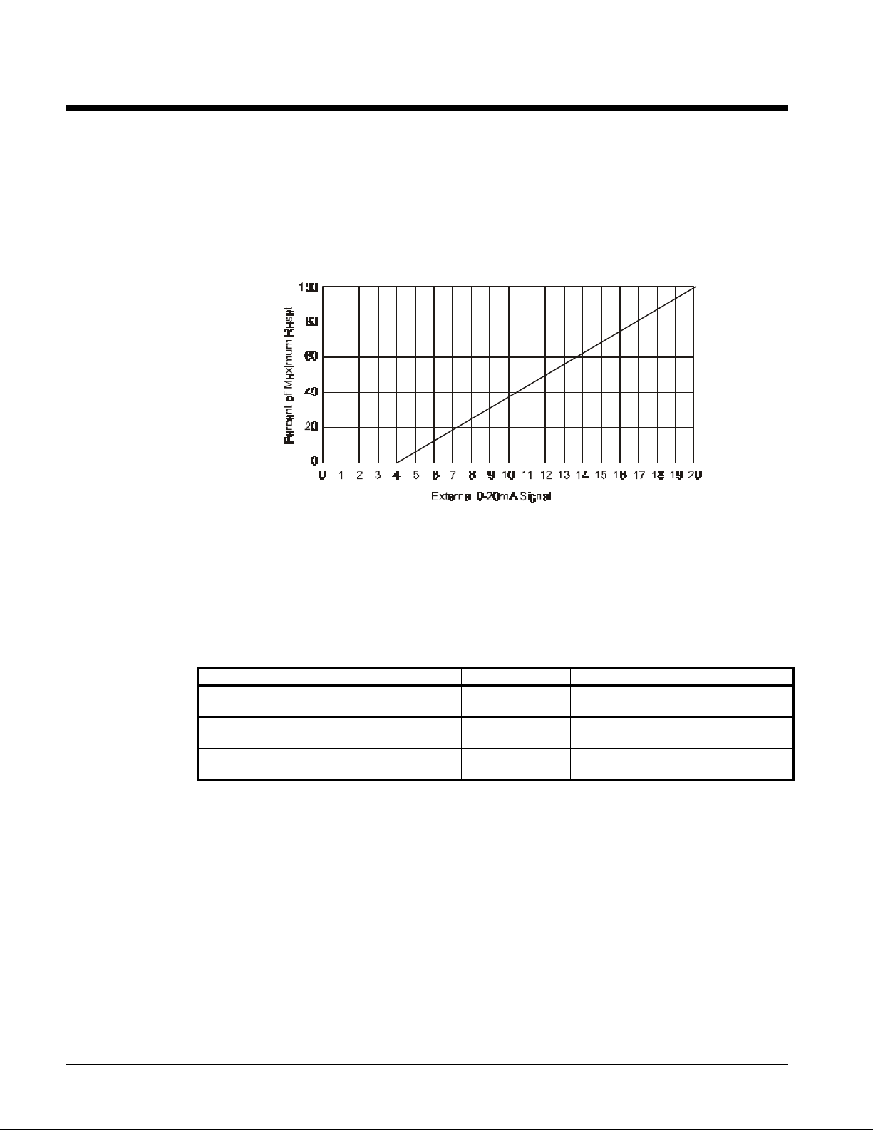
Chilled Water Reset (Remote 4-20mA)
The controller resets the chilled water setpoint based on an external 4 to 20mA signal. At 4mA or less,
no reset will occur. At 20mA, the chilled water setpoint will be reset by an amount equal to the value
stored in the Maximum Reset setpoint. The reset schedule is linear and may be calculated using
Figure 14.
Figure 14, Chilled Water Reset Schedule
Ice Mode
The MicroTech controller has dual chilled water setpoints when ice mode is selected. With an external
reset signal of 4mA or less, the chilled water reset will be zero. If the external reset signal is greater
than 4mA, maximum reset will be in effect. The following set points should be adjusted to
accommodate the reduced ice mode system temperature and pressure.
Table 15
Setpoint Monitors Default Ice Mode
FreezeStat Low Evap Pressure 54 psig
FreezeH20 Leaving Solution 36°F
StpPumpDn Final Pumpdown 34 psig
Note: Once the load is satisfied in Ice Mode, restart of chiller can not occur for 12 hours.
A pressure value equivalent to the
leaving solution temperature minus 10°F
A temperature value equal to the leaving
solution temperature minus 4°F
A pressure value equal to the
FreezeStat setpoint minus 10 psi
Network Reset
The reset mode can be set to "network" if chilled water reset via communications network is desired.
The chiller controller receives a signal from the network master panel in the range of 0% to 100% of
maximum reset.
Return Water Reset
When return water is selected as the reset mode, the MicroTech controller will adjust the leaving
chilled water setpoint to maintain a constant return water temperature equal to the return water
setpoint. The return water temperature is sampled every 5 minutes and a proportional correction is
made to the leaving chilled water setpoint. The corrected leaving water setpoint is never set to a
26 OM ALSMICRO
Page 27

value greater than the return water setpoint and is never set to a value less than the actual leaving
chilled water setpoint.
Remote Demand Limit
The controller will limit the total number of stages based on an external 4 to 20mA signal regardless of
the amount of cooling actually required. A 4mA or less signal will enable all stages while a 20mA
signal will allow only 1 stage to operate. The effect of the reset signal may be calculated by using
Figure 15.
Network Demand Limit
Unit demand limit via network communication may be selected if desired. The chiller controller
receives a demand limit signal from the network master panel in the range of 0% to 100% with 0
equaling no limit.
Keypad Selectable Demand Limit
In the menu Demand Limit, set Manual Demand = Stage, which is below the maximum available for the
unit.
Soft Loading
The soft loading feature limits the number of cooling stages which may be energized by the controller
to prevent unnecessary electrical demand and possible over-shoot of the desired leaving water
temperature. Soft loading is typically used during morning start-up. When the controller enters the
"Cool Staging" mode of operation, the controller will start a count down timer to indicate how long the
unit has been in the cool staging mode. The maximum number of cooling stages will be limited to the
soft load setpoint until the soft load count down timer equals zero.
Max Pull Down
The controller can limit the rate at which the chilled water loop temperature is reduced. Whenever the
rate of temperature decrease exceeds the maximum pull down setpoint, no additional cooling stages
will be activated.
OM ALSMICRO 27
Page 28
Condenser Fan Control
Condenser Fan Staging
The first condenser fan stage will be started in conjunction with the first compressor to provide initial
head pressure control. The MicroTech controller continuously monitors the lift pressure referenced
to several head pressure control setpoints and will adjust the number of operating condenser fans as
required to maintain proper head pressure.
Head Pressure Control
For each circuit, the first stage of condenser fans will be wired in parallel with the compressor output
so that they are energized with the compressor. For chillers with optional SpeedTrol, the first
condenser fan stage will receive a control signal from the AOX board that in turn modulates the
Johnson Controls S66DC-1 to provide variable speed fan operation. Each circuit has 3 additional
digital outputs available for refrigerant head pressure control. Each output will energize an additional
bank of condenser fans with each bank consisting of 1 or 2 fans depending on the size of the unit.
Each output energizes additional heat rejection due to increased airflow across the air-cooled
condenser regardless of the number of fans. If the outdoor ambient temperature is greater than 60°F
when the unit is started, one additional condenser fan stage will be energized. If the outdoor ambient
temperature is greater than 80°F, two additional fan stages will be energized.
ALS unit EERs are maximized by not allowing the last condenser fan stage to operate when the unit
capacity is 25% and the condenser pressure is below 200 psi. The last fan stage will operate if the
condenser pressure is above 220 psi at 25% unit capacity.
Lift Pressure Calculation
The expansion valve determines the minimum acceptable lift pressure. At low tonnage capacities, a
minimum lift pressure of approximately 60 psid must be maintained. At high tonnage capacities, a
higher lift pressure must be maintained to provide proper refrigerant flow through the expansion
valve. Refer to the following table for the lift pressure values maintained at various unit capacities.
Individual head pressure setpoints are provided at 25%, 50%, and 100% circuit capacity to optimize
chiller operation. For operation at 75% capacity and greater with outdoor air temperatures less than
60°F, the minimum lift will automatically be reset downward. The maximum available reset at 100%
capacity is 40 psid while the maximum reset at 75% capacity is 20 psid.
Table 16, Lift Pressure Values
Capacity Setpoint Adjustment Range
25% 90 psig 80 - 120
50% 100 psig 50 - 130
75% 110 psig Fixed
100% 140 psig 110 - 160
28 OM ALSMICRO
Page 29

Figure 15
Lift Pressure Dead Band
The MicroTech controller establishes a dead band above the minimum lift pressure that varies with
circuit capacity. If the lift pressure is within the dead band, no fan staging will occur. Condenser fan
staging will occur as follows for lift pressures above or below the dead band.
Table 17, Condenser Fan Staging With No SpeedTrol
Dead Band Table - No SpeedTrol
Unit Capacity Stage 0 Stage 1 Stage 2 Stage 3 Stage 4 Stage 5 Stage 6
100% 120 100 60 40 30 25 20
75% 120 70 50 30 25 20 20
50% 60 50 30 20 15 15 15
25% 50 30 20 10 10 10 10
Table 18, Condenser Fan Staging With SpeedTrol
Dead Band Table - With SpeedTrol
Unit Capacity Stage 0 Stage 1 Stage 2 Stage 3 Stage 4 Stage 5 Stage 6
100% 40 40 40 40 30 25 20
75% 40 40 40 30 25 20 20
50% 70 30 30 20 15 15 15
25% 80 30 20 10 10 10 10
Condenser Fan Stage Up
Every four seconds, the controller records the difference between the maximum condenser pressure
(as defined by the minimum lift plus the dead band) and the actual condenser refrigerant pressure.
This value is added to the previously recorded values and when the accumulated total is equal to or
greater than the stage up setpoint, the controller starts an additional fan stage. The accumulated total
OM ALSMICRO 29
Page 30
is set to zero whenever a fan stage change occurs or the condenser pressure falls inside the dead
band. Fan stages 5 or 6 will not be enabled unless the circuit capacity is greater than 50%.
High Pressure Stage Up
The controller logic will bring on multiple condenser fan stages if a rapid rise in pressure is detected.
Condenser Fan Stage Down
Every four seconds, the controller records the difference between the minimum condenser pressure
and the actual condenser refrigerant pressure. This value is added to the previously recorded values
and when the accumulated total is equal to or greater than the stage down setpoint, the controller
decrements a fan stage. The accumulated total is set to zero whenever a fan stage change occurs or
the condenser pressure rises inside the dead band. Fan stages 5 or 6 will automatically be disabled
whenever the circuit capacity falls to 50% or less.
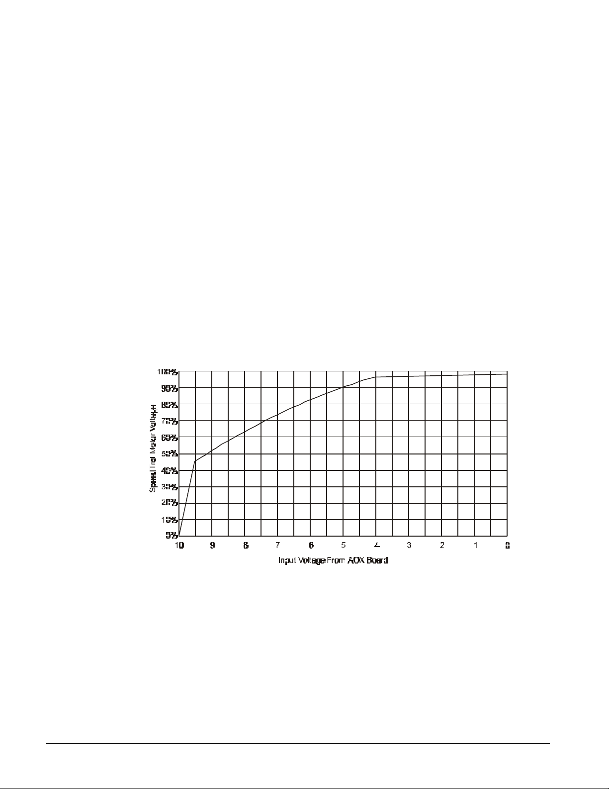
SpeedTrol Logic
When the SpeedTrol option is installed, the MicroTech controller will generate an analog signal via
the AOX board to directly control the S66DC-I variable speed fan motor control. The control signal is
proportional to the condenser pressure's relative position within the lift pressure dead band.
Minimum and maximum fan speed is defined by the minimum and maximum lift pressure setpoints.
When the condenser pressure is below the dead band, the fan speed will be set to 0% and when the
condenser pressure is above the dead band, the fan motor speed will be set to 100%.
Figure 16
30 OM ALSMICRO
Page 31

Pumpdown
Automatic Pumpdown
As the system chilled water requirements diminish, the compressors will be unloaded. As the system
load continues to drop, the electronic expansion valve will be driven to 0 steps, (closed) and the
refrigerant circuit will go through a PumpDown sequence. As the evaporator pressure falls below the
StopPumpDownPres setpoint while pumping down, the compressors and condenser fans will stop. If
the evaporator pressure is greater than the StopPumpDownPres setpoint after 180 seconds have
elapsed, the compressor will stop and the display will read "Can'tPumpDown". The alarm output will
be activated.
Manual Pumpdown
When the compressor is running and the circuit pumpdown switch is moved from the Auto position
to the Stop position, the circuit will pumpdown and stop when the evaporator pressure falls below the
"StopPumpDownPres" setpoint.
When the compressor is not running and the circuit pumpdown switch is moved from the Auto
position to the Stop position, the controller will initiate a pumpdown only if the evaporator pressure is
above the "Begin Pumpdown Pressure" setpoint. The compressor will stop when the evaporator
pressure falls below the "Stop Pumpdown Pressure" setpoint.
An additional pumpdown sequence can be performed by moving the pumpdown switch to the Auto
position for approximately 3 seconds and then back to the Stop position. If the evaporator pressure is
above the "Begin Pumpdown Pressure" setpoint, the controller will initiate a pumpdown sequence
and the compressor will stop when the evaporator pressure falls below the "StopPumpdownPressure"
setpoint.
Service Pumpdown
The normal pumpdown sequence will stop when the evaporator pressure equals the Stop Pumpdown
setpoint pressure. A control setpoint called FullPumpDown has been provided which will allow an
extended pumpdown for service purposes.
The default value for the FullPumpDown setpoint is "No". By changing this setting to "Yes", the
circuit will attempt to pump down to 10 psi during the next pumpdown cycle. If 10 psi cannot be
obtained, the compressor will stop after 300 seconds have elapsed. The setpoint will be set to "No"
automatically at the end of the cycle.
Note: All pumpdown modes are disabled if the system switch (Sl) is in the Stop position.
Note: Compressor capacity during a pumpdown sequence will be 50%.
CAUTION
Do not close any liquid line service valves for a service pumpdown. The compressor
must have liquid injection available whenever it is running. Failure to provide liquid
injection could cause compressor damage.
OM ALSMICRO 31
Page 32

Safety Systems
ALS Unit – MicroTech Control Alarms
Note: Those alarms which are Automatically reset will log an occurrence in the alarm buffer
Unit Alarms - Common to all Unit Refrigerant Circuits
No.
Alarm
Display
1 "BadPhase
Volts"
2 "LossofChW
Flow"
3 "LvgWater
Freeze"
4 "BadLvgWtr
Sen"
5 "No 5VDC
@AI#5"
Circuit Alarms
6 "NoStart-
LoEvap"
Pump
Reset
Auto No Hardware Voltage Incoming power phasing incorrect or not within voltage limits.
Auto Yes No Setpoints Chiller Flow Switch open for more than 3 sec. In Cooling Status
(Auto)Upon flow switch closure * To Prevent chiller freeze-up due to loss of water flow to chiller
Manual Yes Monitor and keypad Chiller leaving water falls below the adjustable Freeze Water Trip
Manual None Controller detects an open or shorted leaving water sensor.
Manual None Voltage at Controller Analog Input not between 4.15 & 4.94 VDC.
Manual No Memory location Evaporator pressure below 4 psi when compressor start is
Down
Adjustable
Setpoints
Range Setting * To prevent operation with reverse rotation, or improper or
unbalanced voltage.
setpoint(36F default)
Logic will not allow this alarm to occur in Auto Control. LWT setpoint
will default to 4 degrees F above the Water Freeze Trip setpoint.
* To prevent chiller freeze-up
* To prevent unit damage due to operation with defective sensor.
* To prevent operation with improper voltage to transducers and
controller
requested. Circuit will not start.
* To prevent start-up with no refrigerant in the unit.
Alarm Description and Reason for Alarm
7 "NoEvapPres
Drop"
8 "FailEXV/
LoChrg"
9 "FailedPre
Purge"
10 "FailLow
Ambient"
Manual No Memory locations Evaporator pressure fails to drop a preset amount during start-up. 6
psig in 16 seconds
* To shutdown circuit and liquid injection if compressor fails to start
due to a possible open contactor.
Manual Evap. Pressure fails to rise after Exv is opened.
* To prevent operation with bad EXV or severe undercharge.
Auto No 40psig is a memory
location, 60sec
timer is adjustable
on Monitor and
Keypad
Manual No Memory location Evaporator Pressure fails to rise above the Freeze stat setpoint after
During startup the EXV will not open until the suction pressure falls
to 40 psig within a default 60 seconds. If these two settings are not
met a non-shutdown alarm will occur.
* To alert service tech that circuit is not pumping normally.
180seconds.
* To prevent operation with evaporator pressure too low during
start-up.
32 OM ALSMICRO
Page 33

No.
Evaporator pressure falls and stays below Frz Stat setpoint for a
11 "No Liquid
Alarm
Display
Start"
Reset
Auto/
Manual
Pump
Down
No Memory location 20 seconds with no liquid at liquid presence sensor or 29 seconds
Adjustable
Setpoints
Alarm Description and Reason for Alarm
with 9 occurrences of liquid
The first occurrence is auto reset while the second is a manual
reset.
* To prevent overheating of the screw due to lack of liquid feed.
12 "No Liquid Run" Manual No Memory locations
for time w/out liquid
13 "FreezeStage
Dwn"
14 "Freezstat
Prot"
Awaiting new
logic
15 "Hi Cond Pres" Manual No Trip adjustable on
16 "HiPresStag
Dwn"
Auto No Keypad and Monitor The evaporator pressure must remain below the Freeze Stat
Manual No Keypad and Monitor
key, Mon
Auto No Trip adjustable on
key, Mon
12 seconds without liquid at 100 and 75% load, 30 seconds w/out
liquid at 50 and 25%
* To prevent overheating of the screw due to lack of liquid feed
during running
setpoint for a period of time to calculate an error(see DD pg 55)
Algorithm: Timer = 113-13 x press diff. Press diff = Freezestat
setpoint - Evap press. Timer determines when the stage down will
occur.
* To prevent evaporator tube freeze due to low pressure operation
timer longer than freezestagedown. The first freezestat protect is
auto clearing. The second is a manual reset if it occurs within 60
minutes of the first occurrence.
* To prevent evaporator tube freeze due to low pressure operation
Condenser pressure exceeds set max. value(380default)
* To prevent excessive condenser pressure operation.
When cond. pressure falls within 20psig of the HP trip setpoint
(default of 380psig) the compressor will stage down. 30 min. must
pass from time of stage down and the OAT must fall 3F below
temperature of stage down before a stage up occurs.
17 "HiPresStage
Hld
18 "Hi Mech Pres" Manual No Hardware(switch) Condenser pressure exceeds Mech. Hi Press switch value(380psig)
19 "Motor Protect" Manual No Hardware(overload
20 "Can'tPump
Down"
21 "Below Min
Lift"
22 "BadEvapPres
Sen"
Auto No Trip adjustable on
key, Mon
)/
Gardistor
(reset overload) * To protect compressor motor from excessive amps or high motor
Auto No Press. setpoint on
Mon, Key
120Sec timer
Memory Address
Manual No Memory addresses When Condenser pressure - Evaporator pressure= < Setpoint for
Manual No None Evaporator Pressure Transducer is failed open or shorted.
When condenser pressure falls within 40psig of HP trip setpoint. The
compressor will not stage up.
* To prevent excessive condenser pressure per Safety agency
requirements
Motor Protection opened due to high amps or high motor temp.
temp operation
Circuit failed to reach Stop pumpdown Setpoint default of 34psig in
90Sec during any pumpdown shutdown
* To alert Service Tech. That circuit may not be pumping properly.
254 seconds this alarm occurs. Setpoint at 25 and 50% load is:
30psig for R22 and 134A, 24psig for 407C. Setpoint at 75 and
100% load is:50psig for R22 and 134A.
* To shutdown the circuit if compressor power is lost during
operation. PreCursor alarm for low press differential conditions.
OM ALSMICRO 33
Page 34

* To prevent operation with bad pressure transducer
34 OM ALSMICRO
Page 35

No.
23 "BadCondPres
Alarm
Display
Sen"
Reset
Manual No None Cond Pressure Transducer is failed open or shorted.
Pump
Down
Adjustable
Setpoints
Alarm Description and Reason for Alarm
* To prevent operation with bad condenser press transducer.
24 "BadSuctTemp
Sen"
25 "LowSubCool
Temp"
26 "HighLiqPress
Drop"
*awaiting
hardware
27 "Repower
a/loss"
28 "LoEvapPress" Manual No Memory Address Protect in case of bad pressure transducer. When the circuit is
Manual No None Suct Temperature Sensor is failed open or shorted.
* To prevent operation with bad suction line temp sensor (used
for Exp. Valve control)
Manual Yes 5F is adjustable on
the monitor, 5min is
a memory address
Manual Yes Hardware setpoint Hardware addition to send an open signal to Digital Inputs
Auto No None If power is lost on running circuit then this alarm appears and logs
Alarm for detecting a unit that is low on charge. Valid only at 75
and 100% load operation. Liquid Line subcooling monitored and if
below a default of 5F for 5 minutes then this alarm will occur.
Both the 5F and 5 minute timers are adjustable from the
* To prevent operation with abnormal low charge quantity
#3(sys1) and #11(sys2) when a pressure differential (charging
valve psig - LI psig) exceeds 35 psig(or what pressure is set on
the switch). Open condition must remain for 15 seconds before
alarm i
*To prevent conditions where the filter dryer is clogged, a liq inj
solenoid fails, or the liquid line shutoff valve is closed.
into buffer upon re-power. A 15min Off:Cycle timer is activated.
Off:Ready circuits are free to start at repower.
*To help identify jobs with poor power supply
running and the evaporator pressure falls below 10 psig.
Pressure must remain below 10 psig for 30 Seconds. Often 2
freezestagedowns will occur just prior to alarm.
29 "Hi Dschrg
Temp"
Manual No Memory Address Applies to 3 compressor units only. Alarm occurs when the
discharge temperature is above 160F.
System Alarms
Alarm conditions that are common to both refrigerant circuits are considered to be system alarms. On
a system alarm, the MicroTech controller will shut down both compressors and energize the alarm
output.
Freeze protect stage down and freeze stat protect
The controller records the amount of time the evaporator refrigerant pressure is below the freeze stat
setpoint (default=54 psi). The magnitude of the error will determine the time delay before a circuit
stage down or alarm shutdown occurs.
Table 19
Error S.D. Delay Alarm Delay
2 psi 100 seconds 160°
4 psi 87 seconds 140°
6 psi 74 seconds 100°
8 psi 60 seconds 100°
10 psi 48 seconds 80°
12 psi 35 seconds 40°
14 psi 22 seconds 40°
Once the time delay is satisfied, the controller will stage down once every 20 seconds. If the
controller stages down to cooling stage 0, the circuit will pump down and the compressor will stop.
The circuit will restart automatically when the anti-cycle timer expires.
OM ALSMICRO 35
Page 36

MicroTech Controller Test Procedures
CAUTION
Service test mode should only be used by McQuayService personnel or other factory
trained technicians. The following test procedures will disable all normal chiller
controls and safeties. All compressors MUST be disabled by opening circuit breakers
or by disconnecting the 3-phase power before beginning tests. Failure to do so can
result in severe compressor damage.
Service Test (Digital Outputs)
Select control mode, Menu 13 (Two Screw Compressor), Control mode, and set the chiller's control
mode to Service Testing. Select Menu 24 (Two Screw Compressor), Service test, and with the Prev or
Next item keys, select the digital output you wish to test. Enter the service password when prompted
by the display. Pressing the Inc key will turn the selected output on, pressing the Decr key will turn it
off. All outputs except 1, 2, 4 and 8 will remain in their last commanded state until the Service Testing
mode is turned off. Manually operating outputs 1 and 2 will drive the electronic expansion valve open
or closed. Compressor MCR outputs 4 and 8 will only remain in the on state for 15 seconds.
Exit the Service Testing mode by selecting the desired chiller operating mode from Menu 13 (Two
Screw Compressor), Control mode.
Service Test (Digital Inputs)
Select control mode, Menu 13 (Two Screw Compressor), Control mode, and set the chiller's control
mode to Service Testing. Select Menu 24 (Two Screw Compressor), Service test, and the Prev or Next
item keys, select test # 16, DHI. The current state of the first 8 digits inputs (0-7) will be represented
on the keypad/display as a row of ones or zeroes where 1 equals "on" and O equals "off'. By
manipulating field wired devices (system switch, motor project, etc.) and watching the keypad/display,
the status of the first eight digital inputs can be verified.
Press the Next item key to select test #17, DH2. The current state of the second 8 digits inputs (8-15)
will be represented on the keypad/display as a row of ones or zeros where 1 equals "on" and 0 equals
"off'. By manipulating field wired devices (flow switch, remote stop switch, etc.) and watching the
keypad/display, the status of the second eight digital inputs can be verified.
Exit the Service Testing mode by selecting the desired chiller operating mode from Menu 13 (Two
Screw Compressor), Control mode.
36 OM ALSMICRO
Page 37

Keypad/Display
Overview
The information stored in the MicroTech controller can be accessed through the keypad using a tree
like structure. This tree structure is divided into Categories, Menus and Menu items. There are three
categories that make up the tree structure: STATUS, CONTROL, and ALARM. Each category is
divided into Menus and each menu into Menu Items. The three categories are described below.
Status Category
Menus and menu items in this category provide information on the MicroTech operating conditions
and the chiller operating conditions. The entries under each menu item in this category provide
information only and are not changeable through the MicroTech keypad.
Control Category
Menus and menu items in this category provide for the input of all the unit parameters.
These include cooling control, compressor control and condenser fan control parameters as well as
time schedules and alarm limits. The entries under these menu items are changeable through the
MicroTech keypad.
Alarm Category
Menus and menu items in this category provide information regarding current and previous alarm
condition.
Display Format
The current MENU is shown on the top line and the current MENU ITEM is shown on the bottom line
of the display. The operator cannot select either English (Inch-Pounds) or metric (SI) units via the
keypad. The units must either be ordered English or Metric or alternatively have revised software
downloaded into the unit in the field.
.
Inch-Pound Units:
Temperature = °F (Fahrenheit)
Pressure = Psi (Pounds per square inch)
Psig (Pounds per square inch, gauge)
Psid (Pounds per square inch, differential)
SI Units:
Temperature = °C (Celsius)
Pressure = kPa (kilo Pasc al)
kPag (kilo Pascal, gauge)
kPad (kilo Pascal, differential)
OM ALSMICRO 37
Page 38

MicroTech Component Test Procedures
Status LED diagnostics
The MCB status LED indications can aid in controller diagnostics. If the status LEDs do not operate
normally as described in the "Component Date" section of this handout (see Table 1 and Table 2),
there is a problem with the MCB. Following are troubleshooting procedures for the various
symptoms.
Red LED remains on
If the red LED remains on after the 5-second self-test period, it is likely that the MCB is defective.
However, this can also occur in some instances if there is a power supply problem. Refer to
"Troubleshooting Power Problems" below.
Red and green LEDs off
If the red and green LEDs do not turn on after power is applied to the controller, there is likely a
defective component or a problem in the controller's power distribution circuits. Refer to
"Troubleshooting Power Problems" below.
Troubleshooting Power Problems
The MCB status receives 18 VAC, center-tapped power from a transformer. It then distributes both 5
VDC and 13 VDC power to various MicroTech components. A problem that exists in any of these
components can affect the MCB and thus the entire control system. Power problems can be caused
by an external short, which can blow a fuse, or a defective component, which can either blow a fuse or
create an excessive load on the power supply. An excessive load can lower the power supply
voltages to unacceptable levels. Use the following procedure to isolate the problem.
Note: This procedure may require two or three spare MCB fuses.
1. Verify that circuit breaker CB1 is closed.
2. Remove the MCB Power In connector and check for 9 VAC between the terminals on the plug
corresponding to terminals 2 and 3 on the board (Figure 2, MCB1). Then check for 9 VAC
between the terminals on the plug corresponding to terminals 1 and 3 on the board. (Readings of
9-12 VAC are acceptable.)
If 9 VAC is present between both sets of terminals, go to step 3.
If 9 VAC is not present between both sets of terminals, check both transformers and all wiring
between the 115 VAC source and the Power In plug.
3. Remove power from the controller by opening circuit breaker CB1. Check the MCB power supply
input fuses (Fl and F2) with an ohmmeter. See Figure 3, ADI. A good fuse will have negligible
resistance through it (less than 2 ohms).
If either or both fuses are blown, replace them. Go to step 4.
If the fuses are intact, the MCB is defective.
4. Reconnect the Power In connector and disconnect all other connectors on the MCB. Cycle
power to the controller (close and then open CB1) and check the power fuses.
If both fuses are intact, go to step 5.
5. If either fuse blows, the MCB is defective. Reconnect the keypad/display ribbon cable (if
equipped with keypad/display door). Cycle power to the controller and check the power fuses.
If both fuses are intact, go to step 6.
If either fuse blows, check the keypad/display and the connecting ribbon cable for shorts. Either
one may be defective.
38 OM ALSMICRO
Page 39

6. Reconnect the analog input ribbon cable. Cycle power to the controller and check the power
fuses.
If both fuses are intact, go to step 7.
If either fuse blows, check the ADI board, the connecting ribbon cable, and the field wiring for
shorts. Any of these may be defective. Try repeating this step after removing or swapping the
ADI board.
7. Reconnect the digital input ribbon cable. Cycle power to the controller and check the power
fuses.
If both fuses are intact, go to step 8.
If either fuse blows, check the ADI board, the connecting ribbon cable, and the field wiring for
shorts. Any of these may be defective.
8. Reconnect the digital output ribbon cable to the MCB. Cycle power to the controller and check
the power fuses.
If both fuses are intact, go to step 9.
If either fuse blows, check Output Board and the connecting ribbon cable. Either of these may be
defective.
9. If there are any AOX-4 boards, reconnect the expansion bus ribbon cable to the MCB: otherwise,
go to stop 10. Cycle power to the controller and check the power fuses.
If both fuses are intact, go to step 10.
If either fuse blows, check the analog output expansion modules (if any), the connecting ribbon
cables, and the field wiring for shorts. Any of these may be defective.
10. With circuit breaker CB1 open, measure the resistance between field terminals "DC-GAD" and "5
VDC". It should be greater than 20 ohms.
If the resistance is greater than 20 ohms, go to step 11 if the controller is equipped with at least
one AOX-4 board or a modem. Otherwise, the problem is indeterminate. Obtain factory service.
If the resistance is less than 20 ohms, it is likely that the keypad/display, the Output Board, or an
external (field supplied) load is excessively loading the MCB's 5 VDC power supply. Isolate the
problem by taking resistance measurements on each of these devices with the wiring
disconnected. The resistance across the power input terminals on the keypad/display (G and 5V)
should be close to infinite. The resistance across the power input terminals on the Output Board
(+ and -) should not be less than 3000 ohms. If the component resistances are proper, check the
resistance of the field supplied loads (if any) and check the wiring and connections throughout
the 5 VDC power supply circuit.
11. Disconnect the connector plugs from the modem and the power plug from all AOX-4 boards (as
applicable). With circuit breaker CB1 open, measure the resistance between field terminals "DCGAD" and " 13 VDC". It should be infinite.
If the resistance is infinite, go to step 12.
If the resistance is not infinite, a short exists somewhere in the 13 VDC power supply wiring.
12. Reconnect the Aux/Out connector plug to the MCB. If there's a modem, reconnect its AMP plug
to port A. With circuit breaker CB1 open, measure the resistance between field terminals "DCGAD" and "13 VDC". It should steadily rise to a value greater than 5000 ohms (within
approximately 30 seconds).
If the resistance rises above 5000 ohms, go to step 13.
If the resistance does not rise above 5000 ohms, the MCB is defective.
13. One at a time, reconnect the modem and each AOX-4 board (as applicable). Each time a
component is reconnected, measure the resistance between field terminals "DC-GAD" and " 13
VDC". It should steadily rise to a value greater than 5000 ohms.
If the resistance rises above 5000 ohms, repeat this step until the modem and all AOX-4 boards
(as applicable) have been checked out. If the problem persists, it is indeterminate. Obtain factory
service.
OM ALSMICRO 39
Page 40

If the resistance does not rise above 5000 ohms, the modem or the AOX-4 board just connected is
defective. (With the power plug disconnected, the resistance across an AOX-4 board's "DC" and
"G" terminals should not be less than 3 meg ohms.)
Figure 17, MCB Power Supply Terminals
Troubleshooting Communications Problems
If a communications problem occurs, check the following items:
Ø Check the port B voltages
Ø Check the port B fuses
Ø Check the network integrity
Ø Check the network addressing
The best way to accomplish these checks is to perform the start-up procedures as specified in the
"Network Commissioning" section of the appropriate IM manual. If these procedures have been
performed and the problem persists, obtain factory service.
Troubleshooting the Keypad/Display Interface
The Keypad/Display Interface is connected to the MCB via a ribbon cable and discrete wiring for the
back light. The MCB provides operating voltages, control signal outputs for the display, and input
conditioning for the keypad inputs.
Display is hard to read
The clarity of the LCD display can be affected by ambient temperature. Typically, less contrast will
result with cooler temperature. If the display is difficult to read, adjust the contrast trim pot, which is
located on the back of the keypad/display assembly.
Back light not lit
The Keypad/Display Interfaces supplied with the MicroTech control panel is equipped with a back
light. If the light does not come on, check for 5 VDC at terminal 9 on the IDC connector on the KDI
and for 5 VDC on the field wiring terminal strip.
Check for 5 VDC on the IDC connector on the MCB aux/out. To check for the 5 VDC on the IDC
connector, pull back the plug about one-eighth of an inch and place the test leads against the exposed
pins. If there is no voltage the MCB is probably defective.
Display is blank or garbled
If the MCB appears to be functioning properly and the display is completely blank or garbled, perform
the following procedure:
1. Try cycling power to the controller by opening and then closing circuit breaker CB1.
2. Try adjusting the contrast trim pot, which is located on the back of the keypad/display assembly.
If the contrast trim pot has no effect, it is likely that either the keypad/display or its ribbon cable
is defective.
40 OM ALSMICRO
Page 41

3. After removing power from the controller, check the ribbon cable and connections between the
keypad/display and the MCB. Look for bent pins. Restore power after reconnecting the ribbon
cable.
4. Try swapping a known good ribbon cable and keypad/display. Swap these components
separately to isolate the problem. Remove power from the controller before disconnecting the
suspect component, and restore power after connecting the replacement component. If the
problem persists, it is likely that the MCB is defective.
Troubleshooting Analog Inputs
An analog input, such as a temperature sensor, is connected to the Analog Input terminal strip on the
ADI board. The ADI board then conditions the analog input. The conditioned input is transferred to
the MCB via a ribbon cable.
Analog input not read by the MCB
If the MCB appears to be functioning properly and the analog input is not being read by the MCB,
perform the following procedure:
1. Try cycling power to the controller by opening and then closing circuit breaker CB1.
2. Check the ribbon cable, power wiring connector, and the field wiring connections from the analog
input device. Look for bent pins, cable on backwards, or miswires. Restore power after
reconnecting all cables and wires.
3. If the problem persists, try swapping a known good ribbon cable, an ADI board, or analog input
device. Swap these components separately to isolate the problem. Remove power from the
controller before disconnecting the suspect component, and restore power after connecting the
replacement component. If the problem persists, it is likely that the MCB is defective.
Troubleshooting Digital Inputs
A digital input device is connected to the Digital Input terminal strip on the Input Conditioning
Module Terminal Board. 24 VAC, supplied by the CSC, is sent to the digital input device via a supply
wire. (CSC is a Chiller System Controller that is a separate MicroTech Network panel). When a
contact in the digital device makes, a return signal is sent back to the Digital Input terminal strip. The
Input Conditioning Module (ICM) then conditions the signal. The conditioned digital input is then
sent to the MCB via a ribbon cable.
Digital input not read by the MCB
If the MCB appears to be functioning properly and the digital input is not being read by the MCB,
perform the following procedure:
1. Try cycling power to the controller by opening and then closing circuit breaker CB1.
2. Check the ribbon cable, power wiring connector, and the field wiring connections from the digital
input device. Look for bent pins, cable on backward, or miswiring. Restore power after
reconnecting all cables and wires.
3. If the problem persists, try swapping a known good ribbon cable, an ADI board, or a digital input
device. Swap these components separately to isolate the problem. Remove power from the
controller before disconnecting the suspect component, and restore power after connecting the
replacement component. If the problem persists, it is likely that the MCB is defective.
Troubleshooting Analog Outputs
Variable voltage or current control signals are sent to analog outputs by the MCB through the Analog
Output Expansion Module (AOX-4) (This can be on the ALS units as the optional fan speed control).
The MCB sends a voltage or current signal to the AOX-4 via a ribbon cable. Jumpers on the AOX-4
determine what type of output will be sent to the analog output device. The analog output signals are
OM ALSMICRO 41
Page 42

sent from the AOX-4 by connecting a two-pin Phoenix connector to the Analog Output Ports on the
AOX-4.
Analog output device is not operating correctly
If the MCB appears to be functioning properly and the analog output device is not operating
correctly, perform the following procedure:
1. Try cycling power to the controller by opening and then closing circuit breaker CB1.
2. Check the ribbon cable(s), power wiring from the transformer to the AOX-4, field wiring
connections from the AOX-4 to the analog output device, and the power wiring from the external
power supply to the output device. Look for bent pins, cable on backwards, or miswiring.
Restore power after reconnecting all cables and wires.
Note: If the analog output signal supplied by the MCB is a voltage signal (0-5, 0-10 VDC),
the external power supply ground must be grounded to the MCB chassis ground.
3. If the problem persists, try swapping a known good AOX-4, ribbon cable(s), analog output
device, or external power supply. Swap these components separately to isolate the problem.
Remove power from the controller and analog output device before disconnecting the suspect
component, and restore power after connecting the replacement component. If the problem
persists, it is likely that the MCB is defective.
Troubleshooting Output Boards
Each output on the Output Board consists of a solid-state relay, a LED, 5-amp fuse, and an MOV
(metal oxide varistor).
Normally, when the MCB commands an output to energize, the solid-state relay turns on and the LED
will glow. The output of each solid-state relay is in series with a 5-amp fuse. These fuses resemble
small resistors and are located on the board adjacent to the relays they serve. The fuses are pressed
into place. They can be removed with needle nose pliers. The MOV, which is located on the
underside of the output board, protects the solid-state relay from high transient voltages. MOVs are
part of the output board and cannot be replaced.
Following are troubleshooting procedures for various symptoms of output board problems.
Note: It should be possible to determine whether a solid-state relay is defective by using
these procedures. However, if you need more information on troubleshooting them, refer to
"Troubleshooting Solid-State relays" below.
42 OM ALSMICRO
Page 43
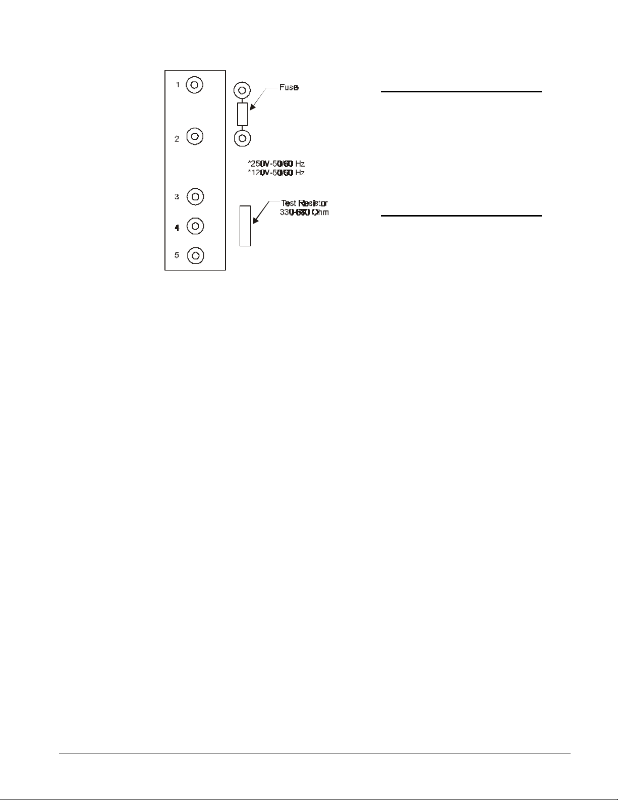
Figure 18, Output Board Relay Socket
WARNING
Electric shock hazard. Can
cause severe injury or death.
Even when power to the panel is
off, solid-state relay socket
terminals 1 and 2 on the output
board could be connected to
high voltage (see Figure 5, EXV
board). Avoid them.
One LED out
If one of the Output Board LEDs fails to illuminate when the MCB is commanding the associated
output to energize, perform the following procedure:
1. Remove power from the controller by opening CB1. Swap the suspect relay with a known good
relay. Try to choose a relay that will not affect unit operation. Restore power by closing CB1.
If the LED does not light, go to step 2.
If the LED lights, the suspect relay is defective.
2. Remove power from the controller. Check the ribbon cable and connections between the OB and
the MCB. Look for bent pins.
If the cable and connections are intact, go to stop 3.
3. Remove the relay from the suspect socket. Install a 330-680 ohm resistor between terminals 3 and
5 as shown in Figure 5, EXV board. Restore power by placing CB1 to the ON position. The LED
should light regardless of the controller's command.
If the output LED illuminates, it is likely that the MCB is defective.
If the LED does not illuminate, the output board is defective.
All LEDs out
If the MCB is commanding at least two outputs to energize and none of the Output Board LEDs are lit,
perform the following procedure:
1. Verify that 5 VDC is present at the Output Board's power terminals.
If 5 VDC is not present, go to step 2.
If 3 VDC is present, check the ribbon cable and connections between the output board and MCB.
Look for bent pins. If the cable and connections are intact, the Output Board or the MCB is
defective.
2. Remove power from the controller by placing CB1 to the OFF position. Disconnect at least one
wire from the power input terminals of the Output Board. The resistance should not be less than
3000 ohms.
If the resistance is greater than the acceptable value, go to step 3.
If the resistance is less the acceptable value, the Output Board is defective.
OM ALSMICRO 43
Page 44

LED lit, output not energized
If the LED of a suspect relay is lit but the load connected to it is not energized, and everything is
intact between the MCB and the control side of the relay, perform the following procedure to isolate
the problem:
1. Verify that 24 or 120 VAC power is present at the suspect output's screw terminal on the Output
Board.
2. Remove power from the controller by opening CB1. Swap the suspect relay with a known good
relay. Try to choose a relay that will not affect unit operation. Restore power by closing CB1.
If the output load energizes, the suspect relay is bad. Replace the relay.
If the output load does not energize (when LED is lit again), check the load circuit wiring and
components.
Output energized, LED not lit
If the LED of a suspect relay is not lit, but the load connected to it is energized, either the solid-state
relay or the MOV is bad. The solid-state relay output and the MOV, which are in parallel, can both fail
closed. Perform the following procedure to isolate the problem:
1. Remove power from the controller by opening CB1. Pull the solid-state relay from the suspect
output's socket.
2. Restore power by closing CB1.
If the output load remains energized when there is no relay in the socket, the output's MOV has
failed and thus the Output Board must be replaced.
If the output load de-energizes, the relay that was pulled is defective.
Contact chatter
Contact chatter is very rapid opening and closing of contacts. It is usually caused by low voltage at
the electromechanical relay or contactor coil. If contact chatter is occurring on a relay or contactor
connected to one of the Output Board solid-state relays, it is also possible that a faulty connection
exists on the power supply terminals of the Aux/Out plug connector on the MCB and the Output
Board. In very rare instances, contact chatter can be caused by a faulty solid-state relay. Perform the
following procedure to isolate the problem:
1. Verify that the voltage at the load's power supply and at the solid-state relay contacts is
adequate.
2. Remove power from the controller by opening CB1. Swap the suspect relay with a known good
relay. Try to choose a relay that will not affect unit operation. Restore power by closing CB1. If
the chatter does not stop, go to step 3. If the chatter stops, the suspect relay is defective.
Replace the relay.
3. Remove power from the controller by opening CB1. Try to improve the connections in the
AUX/Out plug insulation displacement terminals by pressing down on the wires with a small
screwdriver.
4. Check all other wiring and connectors for bent pins or miswires. If the chatter does not stop, the
electromechanical relay or contactor is probably defective.
Troubleshooting Solid-State Relays
As shown on the unit wiring diagrams, the solid-state relays on the Output Boards all have normally
open "contacts". Actually, these contacts do not exist as they do in electromechanical relays.
Instead of using contacts to switch the load, the solid-state relay changes its resistance from low
(closed), when it is energized, to high (open), when it is de-energized. (This high resistance is
approximately 1 00K ohms.) Because the output circuit through the solid-state relay remains
continuous regardless of whether the relay is energized, troubleshooting a solid-state relay with a
voltmeter can be tricky.
44 OM ALSMICRO
Page 45
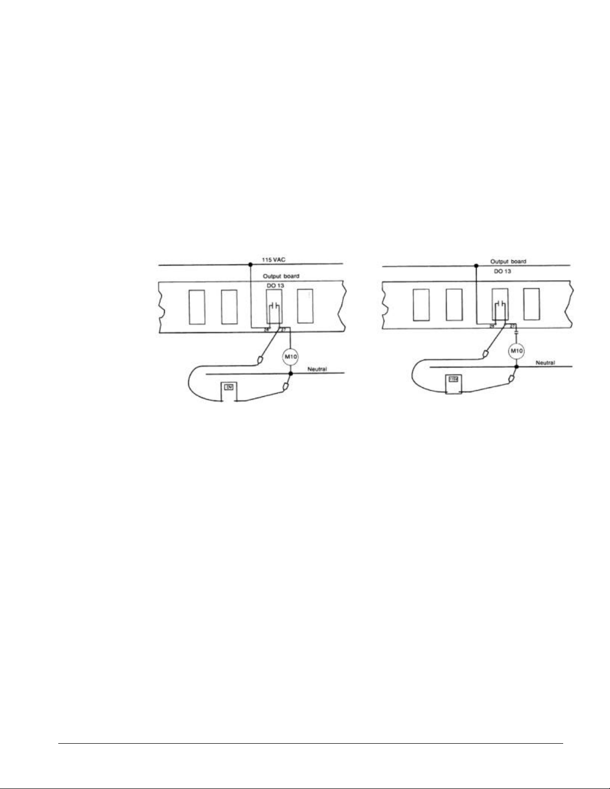
In a typical circuit, a power source is connected across a single relay output and a load (see Figure
19). In this circuit, a solid-state relay will behave like an electromechanical relay. If the relay is
energized, the relay output will be hot. If the relay is deenergized, a small voltage will be present.
The circuit shown in Figure 20 is similar to a typical circuit; the difference is that there is an open set
of contacts, or a disconnection between the relay output and the load. In this circuit, a solid-state
relay will not behave like an electromechanical relay. If the solid-state relay is energized, the relay
output will be hot (as expected). However, if the solid-state relay is de-energized, the relay output will
still appear to be hot. This is because the relay output and the voltmeter form a continuous circuit in
which the relay's resistance, though high, is insignificant compared to the voltmeter's resistance.
This means that nearly all the voltage is dropped across the voltmeter. Therefore, the voltmeter
indicates that voltage is present. If a low wattage light bulb of the appropriate voltage is used instead
of a voltmeter, the bulb's low resistance will load the circuit enough to eliminate the false voltage
indication. In this situation, an incandescent test lamp is a better tool than a voltmeter.
Figure 19, Testing A Typical Relay Circuit Figure 20, Testing A Typical Relay
Circuit With A Disconnection
MCB Replacement
If an MCB board is defective and must be replaced, the proper controller software must be loaded into
the replacement MCB. This can be done either at the factory or at the building site - if a PC equipped
with appropriate Monitor software is available.
The factory will download the proper controller software into a replacement MCB board before it is
shipped if you include the program code with the replacement MCB part order. Only McQuayService
or authorized service agencies are allowed to do this.
Connecting the Communications Trunk
Use the following three procedures to connect the chiller controllers to the network.
Communications cable check
The network communications cable should have been installed in accordance with the instructions in
the "Field Wiring" section of this manual. This procedure will verify that there are no shorts or stray
voltages anywhere in the communications trunk.
OM ALSMICRO 45
Page 46

Before beginning, verify that the port B connectors are disconnected from every controller on the
trunk.
1. Verify that there is no voltage between any conductor and ground.
Use a voltmeter to test for voltage at the field wiring terminal block or directly on the port B
connector of the level-1 controller. With one lead on the control panel chassis (ground), check
for voltage at the "+" "-", and "ground" terminals. There should be no AC or DC voltage (see the
Signal and Terminal columns of Table 3). If the conductors are properly terminated, this check will
test for stray voltage throughout the trunk.
Note: If you get a 2 or 3 VDC reading, it indicates that one or more powered controllers
are connected to the trunk. These controllers should be located and disconnected.
2. Verify that there are no shorts between any two conductors.
Use an ohmmeter to test for shorts at field wiring terminal block or directly on the port B
connector of the level-1 controller. For the three combinations of conductor pairs, there should
be infinite resistance between the conductors. If the conductors are properly terminated, this
check will test for shorts throughout the trunk.
Note: If you find a resistance that is high but less than infinite, it indicates that one or
more non-powered controllers are connected to the trunk. These controllers should be
located and disconnected.
3. Verify that the communications wiring is continuous over the trunk and that the field terminations
are correct. (This step is optional but recommended; to do it, you must know the physical layout
of the network's communications trunk.)
Go to the last controller on one end of the daisy-chain and place a jumper across the "+" to
"ground" and "-" to "ground".
Remove the jumper and repeat this step for the other two conductor pairs: "+" to "ground" and
"-" to "ground".
If there is continuity for each conductor pair, the wiring is continuous and it is likely (but not
guaranteed) that the terminations are correct throughout the trunk.
If there is no continuity for one or more conductor pairs, there may be a break in the trunk or the
terminations at one or more controllers may have been mixed up.
Table 20, Port B Voltages; AMP Type Connector
Port B (RS 485)
Signal Terminal
+ 4 3.0 ± 0.3 VDC
- 3 2.0 ± 0.3 VDC
Ground 5 0.0 ± 0.2 VDC
Acceptable Voltage
Reading
Table 21, Network Communications Field Wiring Terminals
Controller
CSC T11-B+ T11-B- T11-GND
Screw Chiller TB4-54 TB4-53 TB4-55
+ - Ground
Network Comm Field Terminal
46 OM ALSMICRO
Page 47
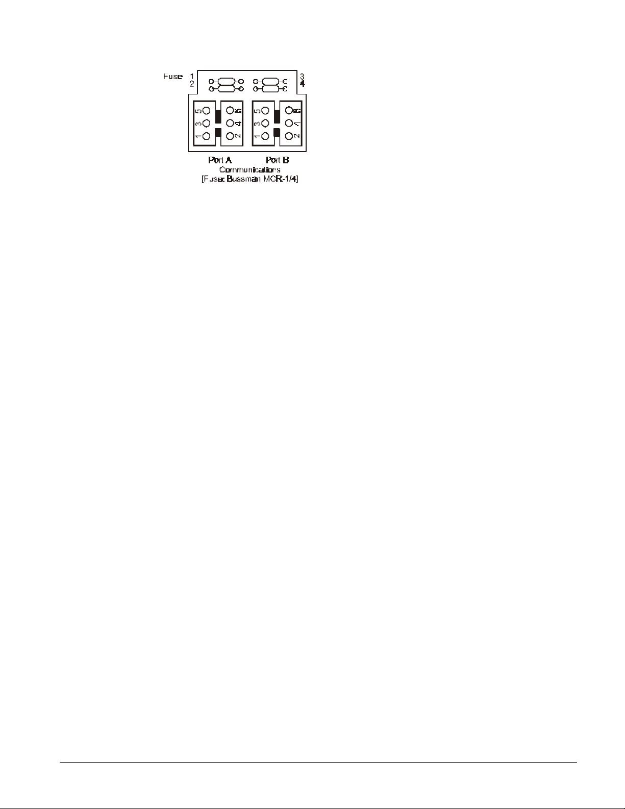
Figure 21, AMP Connector Terminal Configuration
Level-1 controller connection
In order for the chillers and other level-2 controllers in a network to connect and communicate with the
level 1 controller is connected first.
1. Set the network address to 00 (level 1). See "Addressing the Controllers" above for more
information.
2. Push the circuit breaker (CB1) button to power up the CSC and verify that there is power to the
MCB by observing the LEDs.
3. Check the voltages of port B on field wiring terminals (TB2).
Use a DC voltmeter to test for proper voltages. With the ground lead on the control panel
chassis (ground), check the voltage at the "+" "-", and "ground,' terminals. Refer to Table 20,
Port B voltages; AMP type connector, for the correct voltage levels.
If no voltage or improper voltage levels are found, verify that the panel is energized.
4. Plug the network communication AMP connector into port B.
Level-2 controller connection
This procedure will verify that proper communications have begun for each controller as it is
connected to the network. You can connect the level-2 controllers in any order; however, it is better
to follow the daisy-chain as you proceed. This will make troubleshooting easier if communications
problems occur.
As a result of the previous procedures, the network communications connector should be
disconnected from the B port at every controller on the trunk except for the level 1 controller. Be sure
that this is true before beginning this procedure.
For communications to occur, each networked controller must have the proper hex switch setting and
the proper voltages at its port B terminals.
1. Set the network address (hex switch setting) to match the address on the engineering schedule.
Each controller must have a unique address.
2. Turn on power to the level-2 controller. Refer to the controller installation manuals for
information on how to turn on power to each controller.
3. Check the voltages of port B directly on the AMP connector. The trunk must not be connected
to the controller when you do this.
Use a DC voltmeter to test for proper voltages. With the ground lead on the control panel
chassis (ground), check the voltage at the "+" "-", and "ground" terminals. Refer to Table 21,
Port B voltages; AMP type connector, for the correct voltage levels.
If no voltage or improper voltage levels are found, verify that the controller is energized.
4. Check for proper communication trunk voltages at the field wiring terminals (if any) or directly on
the connector. The trunk must not be connected to the controller when you do this.
OM ALSMICRO 47
Page 48

If no voltage or improper voltages are found, check the wiring between the port terminals and the
field terminals (if any), using Table 20, Port B voltages; AMP type connector, and Table 21. Verify
that the three conductors are properly terminated in the network communications connector. If
there is still a problem, verify that the level-1 controller is energized and that the communications
trunk wiring is intact.
5. Plug the network connector into port B.
6. Verify communications have begun between the level-1 controller and the level-2 controller:
To verify communications using Monitor for Windows software, network diagnostics must be
performed. To run network diagnostics, select the pull-down menu "Comm." Select "Network
Diagnostic," which will then display the "Network Diagnostics Parameters Setup" dialog box.
Using the "Network Diagnostics Parameters Setup" dialog box, you can choose to continually
loop the diagnostics, or have a single sweep of each controller being connected to the network.
You can also perform the following functions:
Ø Display Program ID and status
Ø Restrict display of level-3s to units with errors
Ø Clear communications errors if found
Ø Log errors to file
As the different controllers are connected to the network, their information is displayed on the
Network Diagnostic Error Display screen. By looking at the headings labeled "Address" and
"Error codes," network communications to a particular controller can be verified. If there are no
error codes, network communications to the controller was successful. If the "Error code" reads
"Does not respond," a communications problem has occurred. For more on network diagnostics,
see "Chapter 5-Comm Menu" in "MicroTech Monitor for Windows" user's manual.
If a communications problem occurred, check the following items:
Ø Make sure the hex switches on each controller are set to the correct values.
Ø Make sure the controller has power supplied to it. Make sure the communication line is
properly connected to port B.
Ø Make sure the controller is level 2 by directly connecting the PC to it. (You must know how
to change communications passwords to do this.)
7. Go to the next controller and repeat steps 1 through 6. Do this for each controller being
connected to the network.
Note: To verify communications more quickly and easily, use two people in the
commissioning of the network. Because some jobs have units located throughout a building,
having one person perform the commissioning procedure may be difficult. When there are two
people, one person can stay at the PC connected to the level-l controller and the other person
can go to each individual unit controller. Using a radio or other two-way communication
equipment, they can indicate when a specific controller is connected and whether
communications between the controllers is occurring.
48 OM ALSMICRO
Page 49

Keypad Key Functions
The MicroTech keypad consists of twelve pressure sensitive membrane switches (Refer to Figure 7).
These keys are used to step through, access, and manipulate the information in the MicroTech
controller tree structure. The keypad keys are divided into four groups with two or four keys in each.
Keypad password
When changing any menu item entry, the user is prompted to enter the password. The change will
not be allowed until the correct password is entered. The password for ALS units is always the
successive pressing of the following "ACTION" group keys:
Once this has been done, the user can make changes to menu item entries. After entering the correct
password, the controller will allow a 5 minute time period during which the operator may make any
necessary setpoint adjustments. Any keypad activity will reset the timer for the full 5 minutes so the
password only needs to be entered once per session. After 5 minutes of inactivity, the password
access time will expire providing protection against unauthorized users.
Category group
The keys in this group provide quick access to strategic menus throughout the menu tree structure.
This reduces the need to step through all the menus, one by one, in order to reach the desired menu.
"ENTER" "ENTER" "ENTER" "ENTER"
A. STATUS - Pressing the "STATUS" key at any time shifts the display to the first menu of the
STATUS category which is Menu 1, CHILLER STATUS.
B. CONTROL - Pressing the "CONTROL" key at any time shifts the display the first menu of the
CONTROL category which is:
MENU 13 or 16 or 19, CONTROL MODE (2, 3, 4 compressor)
C. ALARMS - Pressing the "ALARMS" key at any time shifts the display to the first menu of the
ALARMS category which is:
MENU 28, 31, 34, #1 CURRENT ALARM 2, 3, 4, compressor)
D. SWITCH - Pressing the "SWITCH" key at any time toggles the display between the current menu
(status/control) item and the related menu (control/status) item somewhere else in the tree
structure. For example, if this key is pressed while the current menu item is menu item 4A
(Leaving Evaporator=), the display shifts to menu item 14A (Leaving Evaporator Setpoint=). This
provides for easy review of actual versus setpoint values.
Menu group
The keys in this group are for stepping from menu to menu in the menu tree-structure.
A. PREV. - Pressing "PREV." shifts the display to the previous menu.
Note: When Menu 1, CHILLER STATUS, is currently in the display (the first menu in the
menu tree structure), pressing "PREV." causes an "end of menus" message to appear in
the display. Pressing "PREV." again causes the display to wrap around to the last menu
in the tree structure.
B. NEXT - Pressing "NEXT" shifts the display to the next menu.
OM ALSMICRO 49
Page 50

Note: When the last menu in the menu tree structure is currently in the display, pressing
"NEXT" causes an "end of menus" message to appear in the display. Pressing "NEXT"
again causes the display to wrap around to the first menu in the structure.
Action Group
The keys in this group are for making changes to unit control parameters and setpoints or for clearing
alarm conditions. Changes do not go into effect nor are they remembered until the ENTER key is
pressed.
Note: Before a change to a parameter can be made or before an alarm can be cleared, the
display prompts the user with an "Enter Password" message. At this prompt, the password
must be entered before the user can continue with the action.
("Enter" "Enter" "Enter" "Enter")
A. INCR. - When changing the value of a menu item entry, pressing "INCR. +" increments the
displayed value to the next higher value or selects the next available option.
B. DECR. - When changing the value of a menu item entry, pressing "DECR.-" decrements the
displayed number to the next lower value or selects the previous available option.
C. ENTER - Once a change has been made to a desired value, pressing "ENTER" locks in the new
value and causes it to take effect.
D. CLEAR - Pressing "ALARMS" followed by "CLEAR" clears the current alarm. Also, when a
change is made to a menu item, pressing "CLEAR" returns the display to the original value as
long as "ENTER" has not yet been pressed.
Note: The cause of an alarm should always be determined and corrected before clearing the
alarm through the keypad.
Example of keypad operation
As an example of using the keypad key functions, consider reprogramming the Leaving Evaporator
Setpoint from 44°F to 42°F. This consists of changing the Menu 14 (Two Screw Compressor), Lvg
evap spts - values for R-22 refrigerant, entry from "44°F to 42°F." Assume Menu 1 Chiller status, is
currently in the display. The following key sequence is followed:
1. Press the "CATEGORY" group "CONTROL" key one time. This switches the display to Menu 13
(Two Screw Compressor), Control mode (the first menu in the "CONTROL" category).
2. Press the "MENU" group "NEXT" key once. This shifts the display to Menu 14 (Two Screw
Compressor), Lvg evap spts - values for R-22 refrigerant. (Leaving Evaporator Setpoint).
3. Press the "ACTION" group "DEC-" key one time. This prompts the user to enter the password.
("Enter" "Enter" "Enter" "Enter").
4. After the "Password Verified" message, press the "ACTION" group "DEC-" key four times. This
changes the menu item entry to 42°F.
5. Press the "ACTION" group "ENTER" key one time. This stores the new entry into the
MicroTech controller memory.
6. Pressing the "CATEGORY" group "STATUS" key then shifts the display back to Menu 1, Chiller
status.
50 OM ALSMICRO
Page 51

Personal Computer Specification
For McQuay Monitor Software
1. IBM PC or 100% true compatible, 486DX or better including:
a) 3 ½ inch, 1.44 MB floppy diskette drive - utilized for loading the MicroTech Monitor program
into the hard disk of the computer. Also provides capability of archiving historical data and
system back-up.
b) 8 Megabyte RAM (Random Access Memory) - The computer must have 8 Megabytes in
order to run the MicroTech Monitor Program.
c) RS232 serial port - A direct communications interface connection between the PC and the
MicroTech Controller. The communications port must be recognized as COM1 or COM2 and
the connector should be a 9 Pin Male.
d) Parallel Printer Port - For hard-copy custom reports of all accumulated data.
e) Mouse or trackball.
f) Hard Disk Drive (120 Megabyte min.) - A mass data storage area for the operator interface
and custom report software.
g) 101 Enhanced Keyboard - Required for more advanced functions of the operator interface
and custom report software.
h) The computer shall include MS-DOS 6.2 or greater, Windows 3.1 or greater and all owner's
manuals.
i) The computer shall have an internal time clock that is battery backed to maintain system time
and date.
j) The computer shall have an internal, 9600-Baud, Hayes compatible modem if remote access
and monitoring of the MicroTech unit controller is desired. The modem shall be addressable
as COM1 or COM2.
2. Multisync Super VGA Color Monitor - For use with the Super VGA graphics.
3. Printer, 192 CPS (Characters Per Second) Epson LQ-510 or equivalent. Must have the ability of
supporting IBM extended character graphics.
4. Printer Cable, For communications connection between the PC and the printer.
The computer is used for changing setpoints, monitoring data, trend logging, diagnostics, and
remotely clearing alarms within the MicroTech system. The computer is normally a dedicated personal
computer, however, the operator may choose to exit the Monitor program from time to time to perform
other functions such as word processing or data manipulation using a spreadsheet program. It
should be noted, however, that for maximum convenience and functionality, the computer should be
considered a dedicated computer for the MicroTech system.
The communications cable from the unit control panel to the personal computer is shielded, twisted
pair wire (Belden #8761 or equal). The communications adheres to the industry standards of RS232C
and the rate of communications is 9600 baud. The recommended maximum distance from the personal
computer to the control panel is 50 feet. If the required distance is in excess of 50 feet, an optional RS232 extension kit is required (contact McQuay).
A voice quality, direct dial telephone line is required if remote access and monitoring of the unit
controller is desired. The phone line should be terminated with a standard RJ-11C modular phone
plug.
OM ALSMICRO 51
Page 52

MicroTech Menu Structure
A complete listing of the information stored in the MicroTech controller tree structure is shown in the
following tables. These tables show the menu numbers and names along with their corresponding
menu items and menu item entries as they appear on the MicroTech display. The # symbol is used
where the controller would normally display a numerical value. Also included in this figure is the
corresponding switch menu for each menu item.
Notes:
1. Status Category - Where more than one menu item entry is listed under a menu item, the list
includes all the entries that can appear in the display for the particular item. The entry that shows
in the display depends on the operating status of the unit.
2. Control Category - Where more than one menu item entry is listed under a menu item, the list
includes all the choices from which the user can select. The selected entry appears in the display.
3. Alarm Category - The entries listed include all the possible alarm messages. The display reads
the alarm conditions that occur.
Status menus
Provide chiller operating information and display of sensor readings. The items listed under these
status menus are affected by the settings under the associated control menus and are not directly
adjusted via the keypad.
Control menus
All adjustable control parameters and setpoints, time schedules, control options and alarm thresholds
are accessed through these menus.
CAUTION
Any changes to these parameters must be determined and implemented by qualified
personnel with a thorough understanding of how these parameters affect the
operation of the unit. Negligent or improper adjustment of these controls may result
in damage to the unit or personal injury.
Alarm menus
Display any alarm conditions that may be present in the unit. All alarm messages are accompanied by
the date and time when the alarm occurred.
52 OM ALSMICRO
Page 53

Menus for Two (2) Screw Compressor Units
Table 22, Two Compressor Menu, Status
Menu Item Display Default Range
Chiller Status
Off: Manual Mode
Off: System Sw
Off: Remote Comm
Off: Remote Sw
Off: Time Clock
Off: Alarm
Off: PumpDnSw's
Off: AmbientLck
1
1
2
3
4
5
6
7
Circ #1 Status
Circ #2 Status
Water Temp's
Circ #1 Pres's
Circ #2 Pres's
Circ #1 Temp's
Starting
Waiting for Flow
Waiting for Load
CoolStageUp
CoolStageDn
Cool Staging #
ManualCool
2 InterStg=xxxsec
Hold stage = xxmin
3
Hi Loop Temp= xxx
Off: SystemSw
Off: ManualMde
Off: Alarm
Off: PumpDwnSw
Off: CycleTime xx
WaitFlooded
OFF: Ready
1
Starting….
Pre-Purge….
Opened EXV….
LowAmbStart
Cooling %Cap=xxx
Pumping Down
See Circ#1 Above
1 Lvg Evap=xxx.x°F(°C) N/A,Open ,Short °F(°C)
2 Ent Evap=xxx.x°F(°C) N/A,Open ,Short °F(°C)
3 Ent Cond=xxx.x°F(°C) N/A,Open ,Short °F(°C)
4 Lvg Cond=xxx.x°F(°C) N/A,Open ,Short °F(°C)
1 Evpxxx.xpsi(kPa) xx°F(°C) 145+oF, Open oF, Short °F(°C)
2 Cndxxx.xpsi(kPa) xx°F(°C) 145+oF, Open oF, Short °F(°C)
3 MinCondPr=xxx#
4 MaxCondPr=xxx#
5 EXV Position=xxx
6 Cond Fan Stage=x
See Circ#1 Above
1 Satur Evap=xxx°F(°C) N/A xx°F(°C)
2 SuctLine=xxx.x°F(°C) N/A,Open, Short °F(°C)
3 Super Ht=xxx.x°F(°C) N/A xx°F(°C)
OM ALSMICRO 53
Page 54

4 Satur Cond=xxx°F(°C) N/A xx°F(°C)
5 CondAppr=xxx°F N/A,Open, Short °F(°C)
6 LiquidLn=xxx.x°F(°C) N/A,Open, Short °F(°C)
7 SubCoolg=xxx.x°F(°C) N/A xx°F(°C)
Table 22, Continued
Menu Item Display Default Range
Circ #2 Temp's
8
9
10
12
See Circ#1 Above
Chiller Amps
1 PercentRLA= xxx%
Comp RunHours
1 #1 Total =xxxxxx
2 #2 Total =xxxxxx
3 #1 @ 25% =xxxxxx
4 #1 @ 50% =xxxxxx
5 #1 @ 75% =xxxxxx
6 #1 @ 100% =xxxxxx
7 #2 @ 25% =xxxxxx
8 #2 @ 50% =xxxxxx
9 #2 @ 75% =xxxxxx
10 #2 @ 100% =xxxxxx
Compr Starts
1 #1 Total =xxxxxx11
2 #2 Total =xxxxxx
Air Temp
1 Outdoor =xxx.x°F(°C) N/A,Open, Short °F(°C)
Table 23, Two Compressor Menu, Control Mode
Menu Item Display Default Range
Control Mode
Manual Unit Off Manual Unit Off
Automatic
Manual Staging
13
1
AutoCirc#1-Off#2
OffCirc#1-Auto#2
Service Testing
2 Manual Stage=xx 0 0-8
54 OM ALSMICRO
Page 55

Table 24, Two Compressor Menu, Set Points
Menu Item Display Default Range
Lvg Evap Spts - (Values for R-22 Refrigerant)
1 Actv Spt=xxx.x°F(°C) Not Changeable
2 Lvg Evap=xxx.x°F(°C) 44.0 10-80
3 CntrlBand=x.x°F(°C) 3.0 1.4-5
4 StartUpD-T=x.x°F(°C) 2.0 0-8
5 ShutDnD-T=x.x°F(°C) 0.5 0-1
6 MaxPullDn=x.x°F(°C) 1.0 .1-2
None, Return, 4-20ma, Ice,
Network, Outdoor
14
15
16
17
18
7 ResetOpt=None None
8 ResetSig=xx.xma
9 MaxChWRst=xx.x°F 10 0-45
10 ReturnSpt=xx.x°F 54 15-80
11 OaTBegRst=xx.x°F 75 0-90
12 OaTMaxRst=xx.x°F 60 0-90
13 HiChWTmp=xx.x°F 70 20-90
14 Amb Lock=xx.x°F 0 -10-60
15 AmbStage=xx.x°F 60 30-80
SoftLoad Spts
1 Time Left = xx min 0 0-254
2 SoftLoad = xx min. 20 0-254
3 SoftLdMaxStg = x 3 2-8
4 LoadDelay = xx sec 15 0-254
CompressorSPT
1 LeadCircuit=Auto Auto Auto, #1, #2
2 InterStg=xxxsec 120 60-240
3 InterStgDiv=x 1/5 1/2-1/10
4 MinST-ST=xxxmin 15 5-40
5 MinSP-ST=xxxmin 5 3-30
6 PrePurSp=xxxsec 60 0-99
Head Pres Spt
1 MinLift 25%=xxx 100 80-120
2 MinLift 50%=xxx 100 90-130
3 MinLift100%=xxx 140 110-160
4 DeadBandMult=x.x 1.0 0.8-1.3
5 StageUpErr=xxx 300 200-990
6 StageDnErr=xxx 80 50-300
Demand Limits
Demand Lim=xstg
DemandSg=xxx.xma
1
Man Demand=xstg 8 4-8
Table 25, Two Compressor Menu, Time/Date
Menu Item Display Default Range
Time / Date
Time=xx: Current hour 0-23
xx: Current min 0-591
19
OM ALSMICRO 55
xx Current sec 0-59
xx/ Current day N/A
xx/ Current mon 1-12
2
xx/xx/xx Current date 1-31
xx Current year 0-99
Page 56

Table 26, Two Compressor Menu, Schedule
Menu Item Display Default Range
Schedule
1 Override=xx.xxHr 0 0-63.5
2 NMP Schedule=xx N/A 1-32
Sun xx: - : 0 0-23
Sun :xx- : 0 0-59
3
20
21
Sun : -xx: 23 0-23
Sun : - :xx 59 0-59
4-9 Same as 3 above
Hol xx: - : 0 0-23
Hol :xx- : 0 0-59
10
Hol : -xx: 23 0-23
Hol : - :xx 59 0-59
Holiday Date
#1 Date=N/A None None-Dec
1
#1 Date= xx 0 0-31
2 #1 Dur=xxDay(s) 0 0-31
Table 27, Two Compressor Menu, Service Test
Menu Item Display Default Range
Service Test
1 #0 Output 0=Off On-Off
2 #1 Output 1=Off On-Off
3 #2 EXV Pos#1=xxx 0 0-760
4 #3 EXV Pos#2=xxx 0 0-760
5 #4 Output 4=Off On-Off
6 #5 Output 5=Off On-Off
7 #6 Output 6=Off On-Off
8 #7 Output 7=Off On-Off
9 #8 Output 8=Off On-Off
10 #9 Output 9=Off On-Off
22
11 #10Output 10=Off On-Off
12 #11Output 11=Off On-Off
13 #12Output 12=Off On-Off
14 #13Output 13=Off On-Off
15 #14Output 14=Off On-Off
16 #15Output 15=Off On-Off
17 #16Output 16=Off On-Off
18 #17Output 17=Off On-Off
19 #18Output 18=Off On-Off
20 #19Output 19=Off On-Off
21 #20 DH1=10110110
22 #21 DH2=10110110
23 #22 AI#5x.xxVdc
Table 28, Two Compressor Menu, Alarm Spts.
Menu Item Display Default Range
Alarm Spts
1 StpPumpDn=xxxpsi 34 10-54
2 FullPumpdown=xx No/Yes
23
56 OM ALSMICRO
3 FreezStat=xxxpsi 54 20-60
4 FreezH2O=xx.x°F 36 N/A 0.5-40
5 Hi Pres =xxpsi 380 280-426
6 LowSubcool=x.x°F 5°F 0-8°F
Page 57

Table 29, Two Compressor Menu, Misc. Setup
Menu Item Display Default Range
Misc Setup
Unit Type=ALS125
Unit Type=ALS140
Unit Type=ALS155
Unit Type=ALS170
1
Unit Type=ALS175
Unit Type=ALS185
Unit Type=ALS195
Unit Type=ALS204
2 Units = xx English English/Metric
3 AirCldCnd=xx Local Local/Remote
4 SpeedTrol = xx No Yes/no
5 Power =xxHz 60 50/60
6 Port A Baud=xx 9600 ukwn,1200,2400,9600
7 Pre-Alarm=xx Blink Blink,open,closed
24
8 Alarm=xx Closed Closed,open,blink(N/O),blink(N/C)
9 OAT Select=xx LCL None,lcl,rmt
10 Amb Lockout=xx No Yes, No
11 Low Amb Opr=xx Yes Yes, No
12 LvgEvpAdj=xx.x°F 0 -.8 - .8
13 EntEvpAdj=xx.x°F 0 -.8 - .8
14 #1EvpAdj=xx.xpsi 0 -2 - +2
15 #2EvpAdj=xx.xpsi 0 -2 - +2
16 #1CndAdj=xx.xpsi 0 -8 - +8
17 #2CndAdj=xx.xpsi 0 -8 - +8
Refrigerant=xx R22, R134a, R407C
18
**Refrigerant type is not selectable on keypad, new code must be downloaded.
19 Min Stage =x 1 1-2
20 LowEvpDTmr=xxM 5 2-15
21 MaxStg1Tmr= xxM 30 10-50M
22 IDENT=SC22U20N
23 Rel. Date MM/DD/YY
Table 30, Two Compressor Menu, Alarms
Menu Item Display Default Range
#1 Curr Alarm
None
HiPresStageHld
HiPresStagDwn
FreezeStageDwn
LossofChWFlow
Can'tPumpDown
NoStart-LoEvap
25
OM ALSMICRO 57
FailedPrePurge
1
FailLow Amb Start
FreezeStatProt
LoEvapPress
Motor Protect
Repower a/loss
No CondWatFlow
NoEvapPresDrop
Below Min Lift
Page 58

Table Continued on Next Page
58 OM ALSMICRO
Page 59

Table 30, Two Compressor Menu (Continued)
Menu Item Display Default Range
No Liquid Run
No Liquid Start
LowSubCoolTemp
HighLiqPressDrop
Hi Dschrg Temp
Hi Cond Press
Hi Mech Pres
BadSuctTempSen
1
BadEvapPresSen
BadCondPresSen
FailEXV/LoChrg
BadPhase/Volts
LvgWaterFreeze
No 5 Vdc @AI#5
BadLvgWaterSen
2 (@ hr:mn mm/dd/yy)
Evap = xx.xpsi
145+psi
3
Openpsi
Shortpsi
Cond = xx.xpsi
450+psi
4
25
26
27
Openpsi
Shortpsi
Suctline=xxx.x°F
n/a °F
5
Open °F
Short °F
LiquidLn=xxx.x°F
n/a °F
6
Open °F
Short °F
Evap Lvg=xxx.x°F
n/a °F
7
Open °F
Short °F
OA/LCnWT=xxx.x°F
n/a °F
8
Open °F
Short °F
9 Capacity = xxx.x%
10 Fan Stage=x
11 Evap Ent= xxx.x°F
12 ExpVPos=xxx
13 Subcool=x.x°F
#2Curr Alarm
1 See #1 Curr Alarm Above
#1Prev Alarms
1 1-same as menu 25
2 1-hr:mn mm/dd/yy
3 2-same as menu 24
4 2-hr:mn mm/dd/yy
5 3-same as menu 24
6 3-hr:mn mm/dd/yy
7 4-same as menu 24
8 4-hr:mn mm/dd/yy
9 5-same as menu 24
OM ALSMICRO 59
Page 60

28
10 5-hr:mn mm/dd/yy
#2Prev Alarms
2 See #1Prev Alarms Above
60 OM ALSMICRO
Page 61
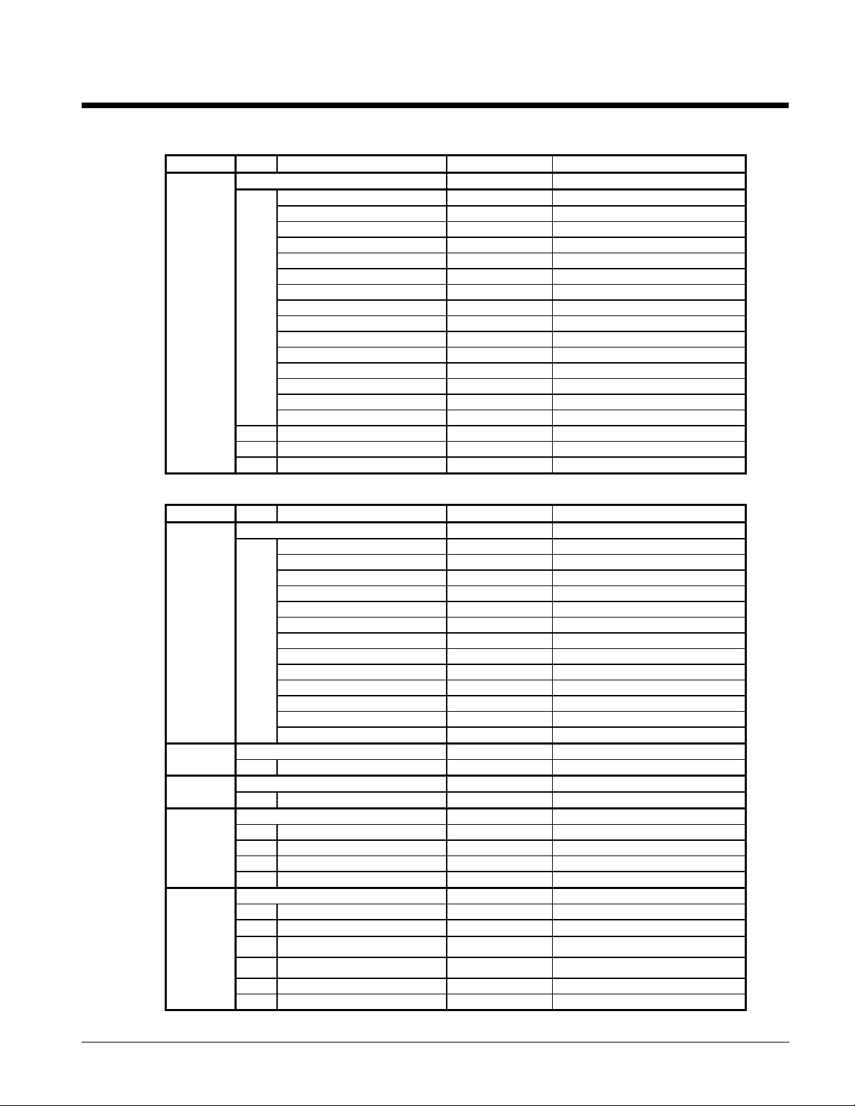
Menus for Three (3) Screw Compressor Units
Table 31, Three Compressor Menu, Test Software
Menu Item Display Default Range
TEST SOFTWARE
Off: Manual Mode
Off: System Sw
Off: Remote Comm
Off: Remote Sw
Off: Time Clock
Off: Alarm
Off: PumpDnSw's
Off: AmbientLck
1
1
Table 32, Three Compressor Menu, Status
Menu Item Display Default Range
2
3
4
5
6
Starting
Waiting for Flow
Waiting for Load
CoolStageUp
CoolStageDn
Cool Staging #
ManualCool
2 InterStg=###sec
3 Hold stage = ##min
4 Hi Loop Temp= ###
Circ #1 Status
Off: SystemSw
Off: ManualMde
Off: Alarm
Off: PumpDwnSw
Off: CycleTime ###
WaitFlooded
OFF: Ready
1
Starting….
Pre-Purge….
Opened EXV….
LowAmbStart
Cooling %Cap=###
Pumping Down
Circ #2 Status
1 Same as Cir#1 above
Circ #3 Status
1 Same as Cir#1 above
Water Temp's
1 Lvg Evap=###.#°F(°C)
2 Ent Evap=###.#°F(°C)
3 Ent Cond=###.#°F(°C) N/A
4 Lvg Cond=###.#°F(°C) N/A
Circ#1 Pres's
1 Evp###.#psi(kPa) ##°F(°C)
2 Cnd###.#psi(kPa) ##°F(°C)
3
MinCondPr=####
4
MaxCondPr=####
5 EXV Position=###
6 Cond Fan Stage=#
OM ALSMICRO 61
Page 62

Table Continued on Next Page
62 OM ALSMICRO
Page 63
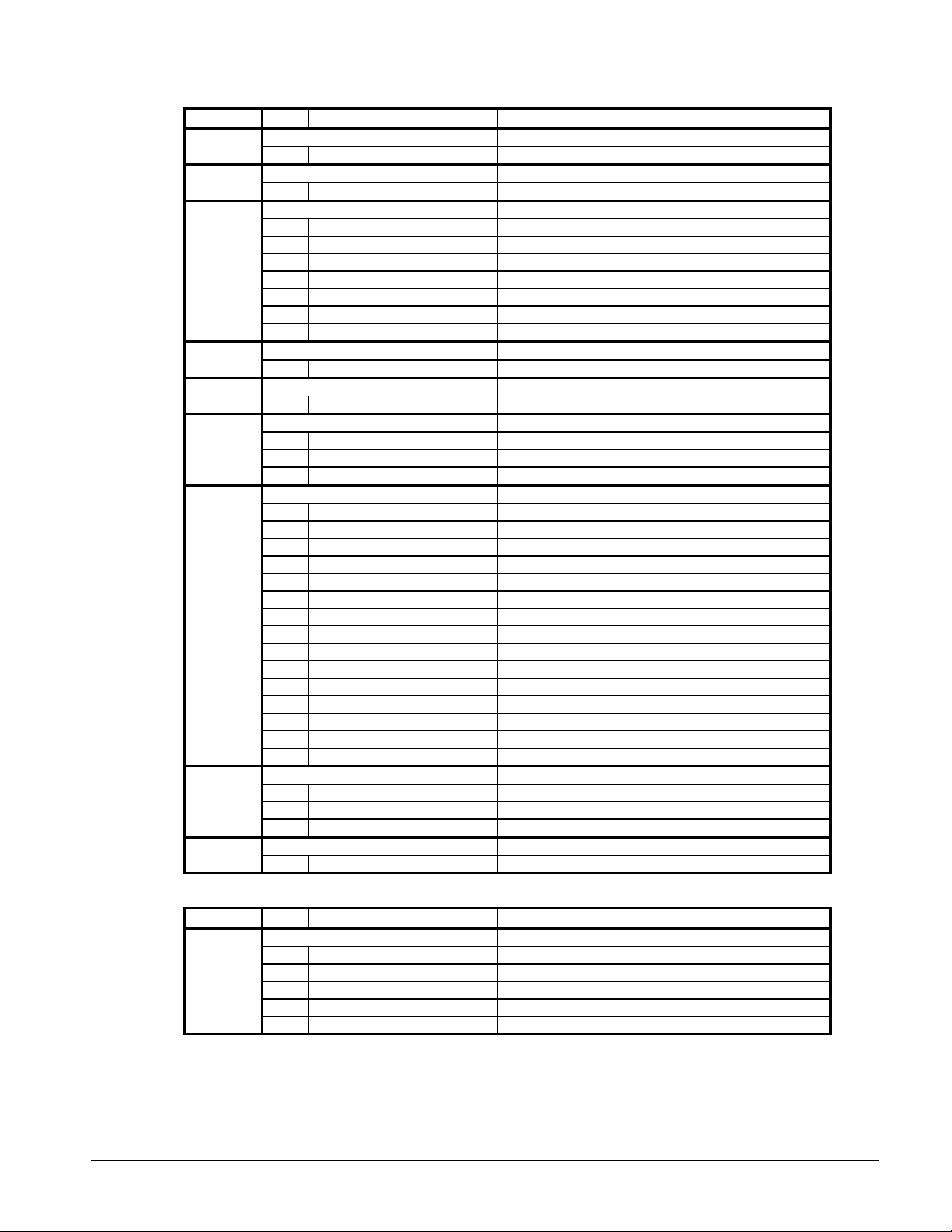
Table 32, Three Compressor Menu, Status (Continued)
Menu Item Display Default Range
Circ#2 Pres's
7
8
9
10
11
12
13
14
15
1 Same as above
Circ#3 Pres's
1 Same as above
Circ#1 Temp's
1 Satur Evap=###°F(°C)
2 SuctLine=###.#°F(°C)
3 Super Ht=###.#°F(°C)
4 Satur Cond=###°F(°C)
5 LiquidLn=###.#°F(°C)
6 SubCoolg=###.#°F(°C)
7 Dscharge=###.#°F(°C)
Circ#2 Temp's
1 Same as above
Circ#3 Temp's
1 Same as above
Chiller amps
1 #1 PrcntRLA= ###% N/A %
2 #2 PrcntRLA= ###% N/A %
3 #3 PrcntRLA= ###% N/A %
Comp RunHours
1 #1 Total =######
2 #2 Total =######
3 #3 Total =######
4 #1 @ 25% =######
5 #1 @ 50% =######
6 #1 @ 75% =######
7 #1 @ 100% =######
8 #2 @ 25% =######
9 #2 @ 50% =######
10 #2 @ 75% =######
11 #2 @ 100% =######
12 #3 @ 25% =######
13 #3 @ 50% =######
14 #3 @ 75% =######
15 #3 @ 100% =######
Compr Starts
1 #1 Total =######
2 #2 Total =######
3 #3 Total =######
Air temp
1 Outdoor =###.#°F(°C)
Table 33, Three Compressor Menu, Control Mode
Menu Item Display Default Range
Control mode
1 Manual Unit Off Manual Unit Off
16
OM ALSMICRO 63
Automatic
Manual Staging 0
Service Testing
2 Manual Stage=## 0 0-12
Page 64

Table 34, Three Compressor Menu, Set Points
Menu Item Display Default Range
Lvg Evap Spts - (values for R-22 refrigerant)
1 Actv Spt=###.#°F(°C) 44 Not Changeable
2 Lvg Evap=###.#°F(°C) 44.0 10-80, .5
3 CntrlBand=#.#°F(°C) 3.0 1-5, .2
4 StartUpD-T=#.#°F(°C) 2.0 0-8, .5
5 ShutDn D-T=#.#°F(°C) 0.5 0-1, .5
6 MaxPullDn=#.#°F(°C) 2.0 .5-5, .1
None, Return, 4-20ma, Network, Ice,
Auto,(123)(132)(213)(231)(312)(321
17
18
19
20
21
7 ResetOpt=None None
8 ResetSig=##.#ma 0.0ma
9 MaxChWRst=##.#°F 10 0-45, .5
10 ReturnSpt=##.#°F 54 15-80, .5
11 No OaTRst=##.#°F 75 0-90, 1
12 MaxOaTRst=##.#°F 60 0-90, 1
13 HiChWTmp=##.#°F 70 20-90, .5
14 Amb Lock=##.#°F 0 -10-60, 1
15 AmbStage=##.#°F 60 30-80, 1
SoftLoad Spts
1 Time Left = ## min 0 0-254, 1
2 SoftLoad = ## min. 20 0-254, 1
3 SoftLdMaxStg = # 7 2-12
4 LoadDelay = ## sec 15 0-254, 1
CompressorSPT
1 Lead/Lag = xxxx Auto
2 InterStg=###sec 120 60-240, 10sec
3 InterStgDiv= ## 1/5 1/ (2-10), x InterStg
4 MinST-ST=###min 15 5-40, 1min
5 MinSP-ST=###min 5 3-30, 1min
6 MinLdTmr=###min 5 5-30, 1min
7 PrePurSp=###sec 60 0-198, 1sec
Head Pres Spt
1 MinLift 25%=### 100 80-120, 1
2 MinLift 50%=### 110 90-130, 1
3 MinLift100%=### 140 110-160, 1
4 DeadBandMult=#.# 1 8-1.3, .1
5 StageUpErr=### 300 200-990, 10
6 StageDnErr=### 80 50 - 300, 10
Demand Limits
1 Demand Lim=#stg 12stg
2 DemandSg=###.#ma 0.0ma
3 Man Demand=###stg 4 6-12
Time / Date
1 Time=##:##:##22
2 Day of week ##/##/##
Outdoor
)
Table 35, Three Compressor Menu, Schedule
Menu Item Display Default Range
Schedule
1 Override=##.##Hr
23
64 OM ALSMICRO
2 NMP Schedule=xx N/A N/A,1-32
3 Day ##:##-##:##
4-9 Same as 3 above
10 Hol xxx ##:##-##:##
Holiday Date24
1 #1 Date= xxx # N/A Jan-Dec
Page 65

2 #1 Dur= ## Day(s) 0 0-31
Service Test
1
#0 Output 0=Off
OFF
On-Off
2
#1 Output 1=Off
OFF
On-Off
3
#2 EXV Pos#1=###00-760
4
#3 EXV Pos#2=###00-760
5
#4 EXV Pos#3=###00-760
6
#5 Output 4=xxx
OFF
On-Off
7
#6 Output 5=xxx
OFF
On-Off
8
#7 Output 6=xxx
OFF
On-Off
9
#8 Output 7=xxx
OFF
On-Off
10
#9 Output 8=xxx
OFF
On-Off
11
#10 Output 9=xxx
OFF
On-Off
12
#11Output 10=xxx
OFF
On-Off
13
#12Output 11=xxx
OFF
On-Off
14
#13Output 12=xxx
OFF
On-Off
15
#14Output 13=xxx
OFF
On-Off
16
#15Output 14=xxx
OFF
On-Off
17
#16Output 15=xxx
OFF
On-Off
18
#17Output 16=xxx
OFF
On-Off
19
#18Output 17=xxx
OFF
On-Off
20
#19Output 18=xxx
OFF
On-Off
21
#20Output 19=xxx
OFF
On-Off
22
#21Output 20=xxx
OFF
On-Off
23
#22Output 21=xxx
OFF
On-Off
24
#23Output 22=xxx
OFF
On-Off
25
#24Output 23=xxx
OFF
On-Off
26
#25Output 24=xxx
OFF
On-Off
27
#26Output 25=xxx
OFF
On-Off
28
#27Output 26=xxx
OFF
On-Off
29
#28Output 27=xxx
OFF
On-Off
30
#29 DH1=########
10110110
31
#30 DH2=########
10110110
32
#31 DH3=########
10110110
33
#32 AI#5=#.## Vdc
4.55
Alarm Spts
1
StpPumpDn=###psi3410-54, 2
2
FullPumpDown=xxNoNo/Yes
3
FreezStat= ##psi5420-60, 2
4
FreezH2O=##.#°F
36
N/A 0.5-40, .5
5
Hi Pres =##psi
380
280-426, 2
6
LowSubcool=#.#°F
5°F
0-8°F, .1
Misc Setup
1
Unit Type=ALS###
ALS205
ALS205, 220, 235, 250, 265, 280
2
Units = xxxxxxx
English
English/Metric
3
SpeedTrol = xxNoYes/no
4
Power =##Hz6050/60
5
Port A Baud=####
9600
1200,2400,9600,ukwn
6
Pre-Alarm=xxxxxx
Blink
Blink,open,closed
7
Alarm=xxxxxx
Closed
Closed,open,blink(N/O),blink(N/C)
8
OAT Select=xxx
Lcl
None,lcl,rmt
9
Amb Lockout=xxNoYes, No
10
Low Amb Opr=xx
Yes
Yes, No
11
LvgEvpAdj=##.#°F0-.8 - .8, .1
12
EntEvpAdj=##.#°F0-.8 - .8, .1
13
#1EvpAdj=##.#psi0-4 - +4, .1
14
#2EvpAdj=##.#psi0-4 - +4, .1
15
#3EvpAdj=##.#psi0-4 - +4, .1
16
#1CndAdj=##.#psi
0
-10 - +15, .1
17
#2CndAdj=##.#psi
0
-10 - +15, .1
18
#3CndAdj=##.#psi
0
-10 - +15, .1
19
Refrigerant=R22
R22
20
IDENT=SC22x20#
3-28 same as 1 and 2 above Up to 14 Holidays Stored
Table 36, Three Compressor Menu, Service Test
Menu Item Display Default Range
25
26
27
Must download correct code to change
OM ALSMICRO 65
Page 66

21
Rel. Date
MM/DD/YY
Table 37, Three Compressor Menu, Alarms
Menu Item Display Default Range
28
#1 Curr Alarm
None
HiPresStageHld
HiPresStageDwn
FreezeStageDwn
LossofChWFlow
Can'tPumpDown
NoStart-LoEvap
FailedPrePurge
FailLowAmbient
FreezeStatProt
HighLiqPressDrop
Motor Protect
Repower a/loss
NoEvapPresDrop
1
Below Min Lift
No Liquid Run
No Liquid Start
Hi Dschrg Temp
Hi Cond Press
Mech Hi Press
BadSuctTempSen
BadEvapPresSen
BadCondPresSen
BadPhase/Volts
LvgWaterFreeze
No 5 Vdc @AI#5
BadLvgWaterSen
LowSubcoolTemp
2 (@ hr:mn mm/dd/yy)
Evap = ##.#psi
145+psi
3
Openpsi
Shortpsi
Cond = ###.#psi
450+psi
4
Openpsi
Shortpsi
Suctline=###.#°F
n/a °F
5
Open °F
Short °F
LiquidLn=###.#°F
n/a °F
6
Open °F
Short °F
7 Subcool = #.#°F
Evap Lvg=###.#°F
n/a °F
8
Open °F
Short °F
9 Evap Ent= ###.#°F
OutsideA= ###.#°F
n/a °F
10
Open °F
Short °F
66 OM ALSMICRO
Page 67
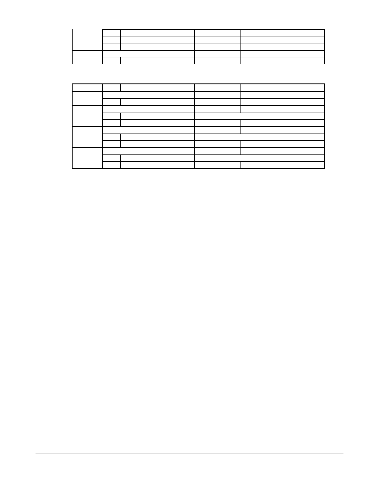
11 Capacity = ###%
12 Fan Stage=#
13 ExpV Pos = ###
29
Table Continued on Next Page
#2 Curr Alarm
1 Same as #1Curr above
Table 37, Three Compressor Menu, Alarms (Continued)
Menu Item Display Default Range
#3 Curr Alarm30
1 Same as #1Curr above
31
32
33
#1Prev Alarms
1 1-Alarm Title(menu22) 5 Alarms Stored in Buffer
2 1-hr:mn mm/dd/yy
#2Prev Alarms
1 1-Alarm Title(menu22) 5 Alarms Stored in Buffer
2 1-hr:mn mm/dd/yy
#3Prev Alarms
1 1-Alarm Title(menu22) 5 Alarms Stored in Buffer
2 1-hr:mn mm/dd/yy
OM ALSMICRO 67
Page 68

Menus for Four (4) Screw Compressor Units
Table 38, Four Compressor Menu, Test Software
Menu Item Display Default Range
Test Software
Off: Manual Mode
Off: System Sw
Off: Remote Comm
Off: Remote Sw
Off: Time Clock
Off: Alarm
Off: PumpDnSw's
Off: AmbientLck
1
1
Table 39, Four Compressor Menu, Status
Menu Item Display Default Range
2
3
4
5
7
8
Starting
Waiting for Flow
Waiting for Load
CoolStageUp
CoolStageDn
Cool Staging #
ManualCool
2 InterStg=###sec
3 Hold stage = ##min
4 Hi Loop Temp= ###
Circ #1 Status
Off: SystemSw
Off: ManualMde
Off: Alarm
Off: PumpDwnSw
Off: CycleTime ###
WaitFlooded
OFF: Ready
1
Starting….
Pre-Purge….
Opened EXV….
LowAmbStart
Cooling %Cap=###
Pumping Down
Circ #2 Status
1 Same as Cir#1 above
Circ #3 Status
1 Same as Cir#2 above
Circ #4 Status
1 Same as Cir#3 above
Water Temp's
1 Lvg Evap=###.#°F(°C)6
2 Ent Evap=###.#°F(°C)
Circ#1 Pres's
1 Evp###.#psi(kPa) ##°F(°C)
2 Cnd###.#psi(kPa) ##°F(°C)
3 MinCondPr=####
4 MaxCondPr=####
5 EXV Position=###
6 Cond Fan Stage=#
Circ#2 Pres's
1 Same as above
68 OM ALSMICRO
Page 69

10
9
Circ#3 Pres's
1 Same as above
Circ#4 Pres's
1 Same as above
OM ALSMICRO 69
Page 70

Table 39, Four Compressor Menu, Status (Continued)
Menu Item Display Default Range
Circ#1 Temp's
1 Satur Evap=###°F(°C)
2 SuctLine=###.#°F(°C)
11
12
13
14
16
17
18
3 Super Ht=###.#°F(°C)
4 Satur Cond=###°F(°C)
5 LiquidLn=###.#°F(°C)
6 SubCoolg=###.#°F(°C)
Circ#2 Temp's
1 Same as above
Circ#3 Temp's
1 Same as above
Circ#4 Temp's
1 Same as above
Chiller amps
1 #1+3 PctRLA= ###% N/A %15
2 #2+4 PctRLA= ###% N/A %
Comp RunHours
1 #1 Total =######
2 #2 Total =######
3 #3 Total =######
4 #4 Total =######
5 #1 @ 25% =######
6 #1 @ 50% =######
7 #1 @ 75% =######
8 #1 @ 100% =######
9 #2 @ 25% =######
10 #2 @ 50% =######
11 #2 @ 75% =######
12 #2 @ 100% =######
13 #3 @ 25% =######
14 #3 @ 50% =######
15 #3 @ 75% =######
16 #3 @ 100% =######
17 #4 @ 25% =######
18 #4 @ 50% =######
19 #4 @ 75% =######
20 #4 @ 100% =######
Compr Starts
1 #1 Total =######
2 #2 Total =######
3 #3 Total =######
4 #4 Total =######
Air temp
1 Outdoor =###.#°F(°C)
Table 40, Four Compressor Menu, Control Mode
Menu Item Display Default Range
Control Mode
Manual Unit Off Manual Unit Off
Automatic
1
Manual Staging 0
19
70 OM ALSMICRO
Service Testing
2 Manual Stage=## 0 0-16
3 Circ 1 Mode=xxxx Auto Auto, Off
4 Circ 2 Mode=xxxx Auto Auto, Off
5 Circ 3 Mode=xxxx Auto Auto, Off
Page 71

6 Circ 4 Mode=xxxx Auto Auto, Off
Table 41, Four Compressor Menu, Set Points
Menu Item Display Default Range
Lvg Evap Spts - (values for R-22 refrigerant)
1 Actv Spt=###.#°F(°C) 44 Not Changeable
2 Lvg Evap=###.#°F(°C) 44.0 10-80, .5
3 CntrlBand=#.#°F(°C) 3.0 1.4-5, .2
4 StartUpD-T=#.#°F(°C) 2.0 0-8, .5
5 ShutDn D-T=#.#°F(°C) 0.5 0-1, .5
6 MaxPullDn=#.#°F(°C) 2.0 .5-5, .1
None, Return, 4-20ma, Network, Ice,
Auto,(1234)(1324)(2143)(2413)(3412)(3142
)(4321)(4231)
20
21
22
23
24
7 ResetOpt=None None
8 ResetSig=##.#ma 0.0ma
9 MaxChWRst=##.#°F 10 0-45, .5
10 ReturnSpt=##.#°F 54 15-80, .5
11 OaTBegRst=##.#°F 75 0-90, 1
12 OaTMaxRst=##.#°F 60 0-90, 1
13 HiChWTmp=##.#°F 70 20-90, .5
14 Amb Lock=##.#°F 0 -10-60, 1
15 AmbStage=##.#°F 60 30-80, 1
SoftLoad Spts
1 Time Left = ## min 0 0-254, 1
2 SoftLoad = ## min. 20 0-254, 1
3 SoftLdMaxStg = # 12 1-16
4 LoadDelay = ## sec 15 0-254, 1
CompressorSPT
1 Lead = xxxx Auto
2 InterStg=###sec 120 60-480, 10sec
3 InterStgDiv= ## 1/5 1/ (2-10), x InterStg
4 MinST-ST=###min 15 5-40, 1min
5 MinSP-ST=###min 5 3-30, 1min
6 PrePurSp=###sec 60 0-198, 2sec
Head Pres Spt
1 MinLift 25%=### 100 80-120, 1
2 MinLift 50%=### 110 90-130, 1
3 MinLift100%=### 140 110-160, 1
4 DeadBandMult=#.# 1 .8-1.3, .1
5 StageUpErr=### 300 200-990, 10
6 StageDnErr=### 80 50 - 300, 10
Demand Limits
1 Demand Lim=#stg 16stg
2 DemandSg=###.#ma 0.0ma
3 Man Demand=###stg 16 8-16
Time / Date
1 Time=##:##:##25
2 Day of week ##/##/##
Outdoor
Table 42, Four Compressor Menu, Schedule
Menu Item Display Default Range
Schedule
1 Override=##.##Hr
26
27 Holiday Date
OM ALSMICRO 71
2 NMP Schedule=xx N/A N/A,1-32
3 Day ##:##-##:##
4-9 Same as 3 above
10 Hol xxx ##:##-##:##
Page 72

1 #1 Date= xxx # N/A Jan-Dec
2 #1 Dur= ## Day(s) 0 0-31
3-28 same as 1 and 2 above Up to 14 Holidays Stored
72 OM ALSMICRO
Page 73

Table 43, Four Compressor Menu, Service Test
Menu Item Display Default Range
Service Test
1 #0 Output 0=Off OFF On-Off
2 #1 Output 1=Off OFF On-Off
3 #2 EXV Pos#1=### 0 0-760
4 #3 EXV Pos#2=### 0 0-760
5 #4 EXV Pos#3=### 0 0-760
6 #5 EXV Pos#4=###
7 #6 Output 4=xxx OFF On-Off
8 #7 Output 5=xxx OFF On-Off
9 #8 Output 6=xxx OFF On-Off
10 #9 Output 7=xxx OFF On-Off
11 #10 Output 8=xxx OFF On-Off
12 #11 Output 9=xxx OFF On-Off
13 #12Output 10=xxx OFF On-Off
14 #13Output 11=xxx OFF On-Off
15 #14Output 12=xxx OFF On-Off
16 #15Output 13=xxx OFF On-Off
17 #16Output 14=xxx OFF On-Off
18 #17Output 15=xxx OFF On-Off
19 #18Output 16=xxx OFF On-Off
20 #19Output 17=xxx OFF On-Off
21 #20Output 18=xxx OFF On-Off
28
29
Table Continued on Next Page
22 #21Output 19=xxx OFF On-Off
23 #22Output 20=xxx OFF On-Off
24 #23Output 21=xxx OFF On-Off
25 #24Output 22=xxx OFF On-Off
26 #25Output 23=xxx OFF On-Off
27 #26Output 24=xxx OFF On-Off
28 #27Output 25=xxx OFF On-Off
29 #28Output 26=xxx OFF On-Off
30 #29Output 27=xxx OFF On-Off
31 #30Output 28=xxx
32 #31Output 29=xxx
33 #32Output 31=xxx
34 #33Output 32=xxx
35 #34Output 33=xxx
36 #35Output 34=xxx
37 #36Output 35=xxx
38 #37Output 36=xxx
39 #38Output 37=xxx
40 #39Output 38=xxx
41 #40 DH1=######## 10110111
42 #41 DH2=######## 10110110
43 #42 DH3=######## 10110100
44 #43 DH4=######## 10110100
45 #44 AI#5=#.## Vdc 4.55
Alarm Spts
1 StpPumpDn=###psi 34 10-54, 2
2 FullPumpDown=xx No No/Yes
3 FreezStat= ##psi 54 20-60, 2
4 FreezH2O=##.#°F 36 N/A 0.5-40, .5
5 Hi Pres =##psi 380 280-426, 2
6 LowSubcool=#.#°F 5°F 0-8°F, .1
OM ALSMICRO 73
Page 74

Table 43, Four Compressor Menu, Service Test (Continued)
Menu Item Display Default Range
Misc Setup
1 Unit Type=ALS### ALS300 ALS315, 330, 340, 360, 370, 380, 425
2 Units = xxxxxxx English English/Metric
3 SpeedTrol = xx No Yes/No
4 Power =##Hz 60 50/60
5 Port A Baud=#### 9600 1200,2400,9600,ukwn
6 Pre-Alarm=xxxxxx Blink Blink,open,closed
7 Alarm=xxxxxx Closed Closed,open,blink(N/O),blink(N/C)
8 OAT Select=xxx Lcl None,lcl,rmt
9 Amb Lockout=xx No Yes, No
10 Low Amb Opr=xx Yes Yes, No
30
11 LvgEvpAdj=##.#°F 0 -.8 - .8, .1
12 EntEvpAdj=##.#°F 0 -.8 - .8, .1
13 #1EvpAdj=##.#psi 0 -4 - +4, .1
14 #2EvpAdj=##.#psi 0 -4 - +4, .1
15 #3EvpAdj=##.#psi 0 -4 - +4, .1
16 #4EvpAdj=##.#psi 0 -4 - +4, .1
17 #1CndAdj=##.#psi 0 -10 - +15, .1
18 #2CndAdj=##.#psi 0 -10 - +15, .1
19 #3CndAdj=##.#psi 0 -10 - +15, .1
20 #4CndAdj=##.#psi 0 -10 - +15, .1
21 Refrigerant=R22 R22 Must download correct code to change
22 IDENT=SC42x20x
23 REL. 00/00/00
Table 44, Four Compressor Menu, Alarms
Menu Item Display Default Range
#1 Curr Alarm
None
HiPresStageHld
HiPresStageDwn
FreezeStageDwn
LossofChWFlow
Can'tPumpDown
NoStart-LoEvap
FailedPrePurge
FailLowAmbient
FreezeStatProt
HighLiqPressDrop
Motor Protect
Repower a/loss
NoEvapPresDrop
31
1
Below Min Lift
No Liquid Run
No Liquid Start
Hi Dschrg Temp
Hi Cond Press
Mech Hi Press
BadSuctTempSen
BadEvapPresSen
BadCondPresSen
BadPhase/Volts
LvgWaterFreeze
No 5 Vdc @AI#5
BadLvgWaterSen
LowSubCoolTemp
2 (@ hr:mn mm/dd/yy)
74 OM ALSMICRO
Page 75

Table Continued on Next Page
OM ALSMICRO 75
Page 76

Table 44, Four Compressor Menu, Alarms (Continued)
Menu Item Display Default Range
Evap = ##.#psi
145+psi
3
Openpsi
Shortpsi
Cond = ###.#psi
450+psi
4
Openpsi
Shortpsi
Suctline=###.#°F
n/a °F
5
Open °F
Short °F
LiquidLn=###.#°F
n/a °F
6
31
32
33
34
Open °F
Short °F
7 Subcool = #.#°F
Evap Lvg=###.#°F
n/a °F
8
Open °F
Short °F
9 Evap Ent= ###.#°F
OutsideA= ###.#°F
n/a °F
10
Open °F
Short °F
11 Capacity = ###%
12 Fan Stage=#
13 ExpV Pos = ###
#2 Curr Alarm
1 Same as #1 Curr above
#3 Curr Alarm
1 Same as #1 Curr above
#4 Curr Alarm
1 Same as #1 Curr above
#1Prev Alarms
1 1-Alarm Title(menu22) 5 Alarms Stored in Buffer35
2 1-hr:mn mm/dd/yy
#2Prev Alarms
1 1-Alarm Title(menu22) 5 Alarms Stored in Buffer36
2 1-hr:mn mm/dd/yy
#3Prev Alarms
1 1-Alarm Title(menu22) 5 Alarms Stored in Buffer37
2 1-hr:mn mm/dd/yy
#4Prev Alarms
1 1-Alarm Title(menu22) 5 Alarms Stored in Buffer38
2 1-hr:mn mm/dd/yy
76 OM ALSMICRO
Page 77
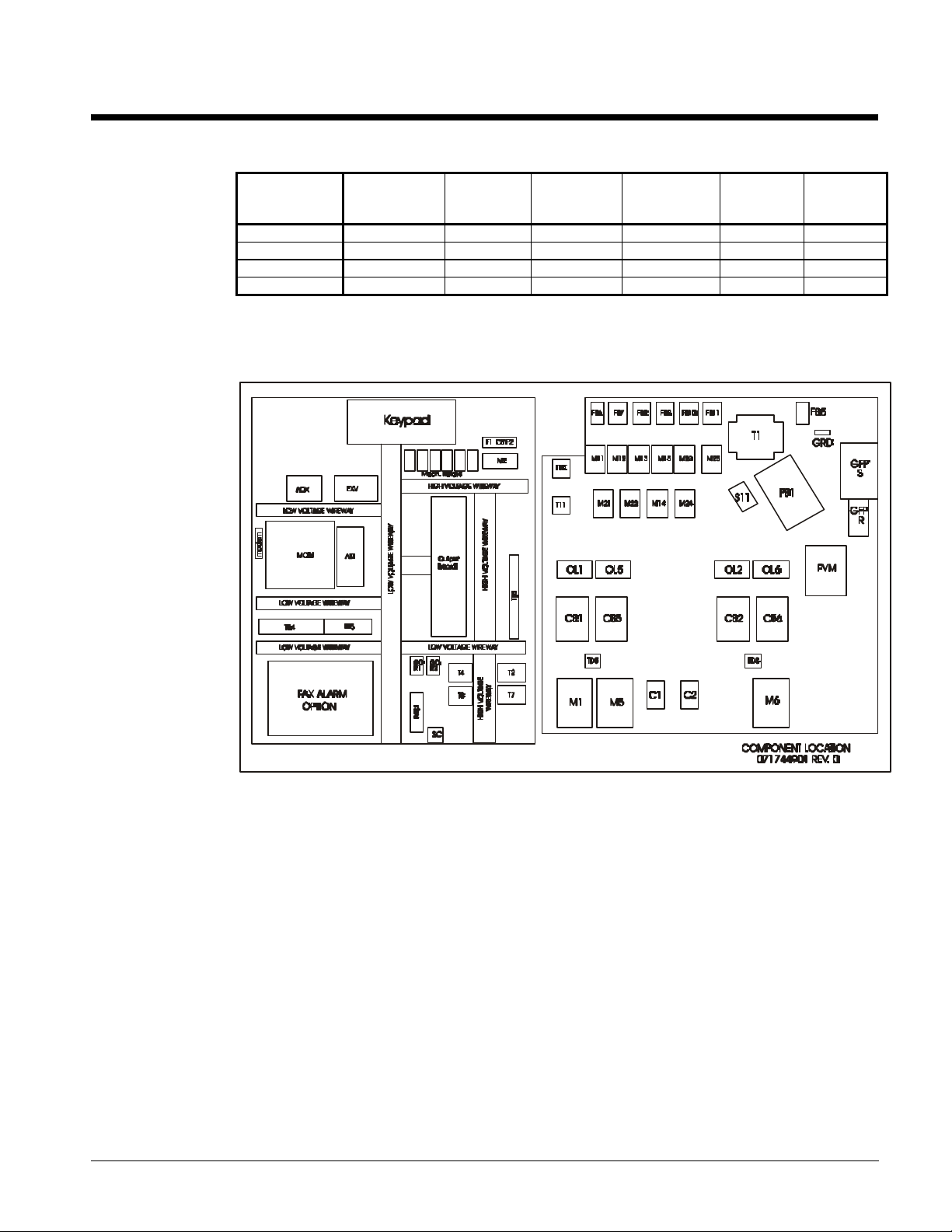
Schematics and Drawings
Table 45, ALS Schematics & Diagrams
Unit
ALS 070A-100A 073176801 704352C-01 074558501 074558601 074558401 719740C-01
ALS 125A-204A 717449-01 704352C-01 716995D-01 716996D-01 716997D-01 719740C-01
ALS 205A-280A 717460-01 704352C-01 718507D-01 718508D-01 718509D-01 719740C-01
ALS 300A-425A 719869-01 704352C-01 718640D-01 718641D-01 718642D-01 719740C-01
Control Cabinet Layout - ALS 125A-204A
Control
Cabinet
Layout
Wiring
Legend
Unit
Control
Stage
Output
MicroTech
Schematic
Field
Wiring
OM ALSMICRO 77
Page 78

Control Cabinet Layout - ALS 205A-280A
Control Cabinet Layout - ALS 300A-425A
78 OM ALSMICRO
Page 79

ALS 125A - 204A Unit Control
OM ALSMICRO 79
Page 80

ALS 205A - 208A Unit Control
80 OM ALSMICRO
Page 81

ALS 300A - 425A Unit Control
OM ALSMICRO 81
Page 82

ALS 125A - 204A Staging Output Schematic
82 OM ALSMICRO
Page 83
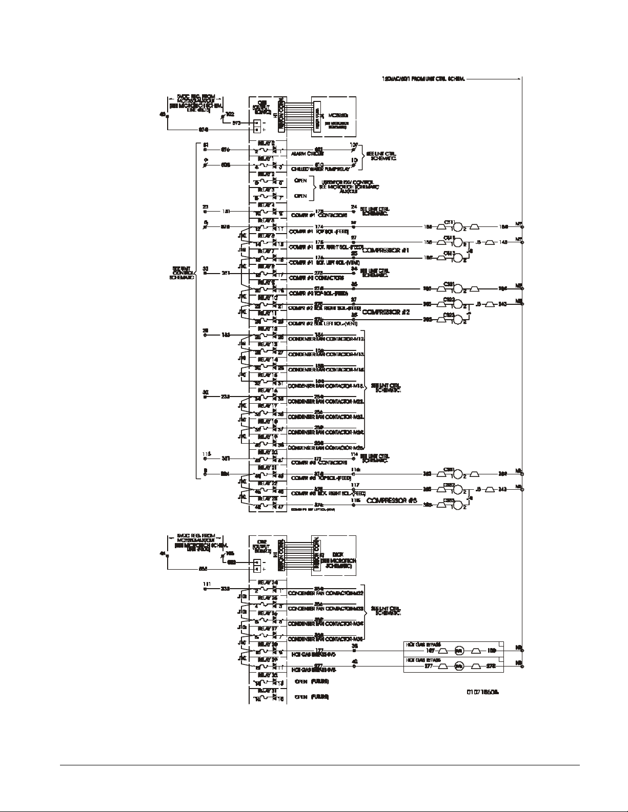
ALS 205A - 280A Staging Output Schematic
OM ALSMICRO 83
Page 84

ALS 300A - 425A Staging Output Schematic
84 OM ALSMICRO
Page 85

ALS 125A - 204A MicroTech Schematic
OM ALSMICRO 85
Page 86

ALS 125A - 204A MicroTech Schematic, continued
86 OM ALSMICRO
Page 87

ALS 205A - 280A MicroTech Schematic
OM ALSMICRO 87
Page 88
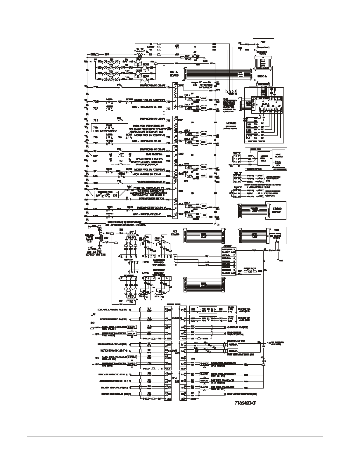
ALS 300A - 425A MicroTech Schematic
88 OM ALSMICRO
Page 89
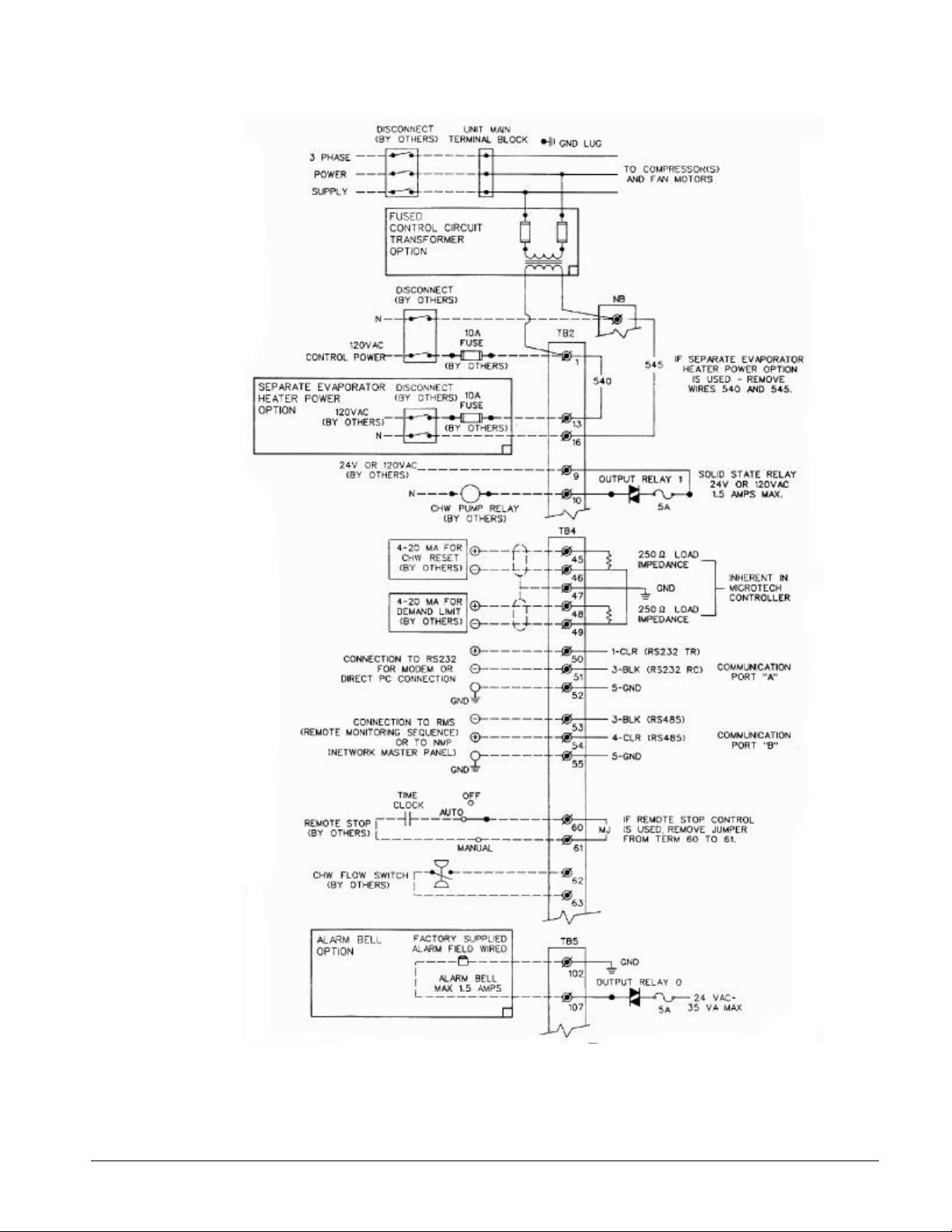
ALS Field Wiring - 0719740C-01
OM ALSMICRO 89
Page 90

Wiring Legend
90 OM ALSMICRO
Page 91

Page 92

Post Office Box 2510, Staunton, Virginia 24402-2510 • (800) 432-1342 • www.mcquay.com
 Loading...