

Page 1
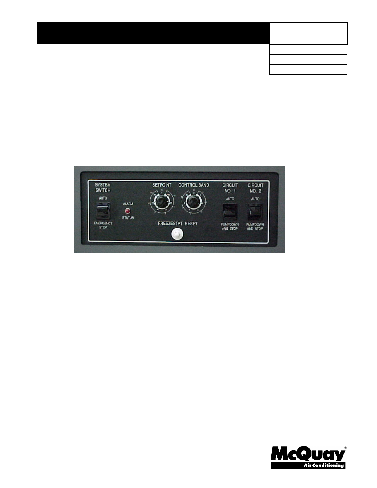
Installation and Operating Manual
Leaving Water Controller, AS-UNT33n-1
Applied to ALR C/D/E and WHR D/E
IOM UNT33n
Group: Chiller
Date: May 2000
Supersedes: IM 552
© 1996 McQuay International
Page 2

Table of Contents
Introduction........................................................................................3
Specifications.....................................................................................4
Installation..........................................................................................5
Dimensional Data................................................................................6
Electrical Data.....................................................................................7
Operation...........................................................................................9
Additional Features............................................................................11
Settings And Adjustments.................................................................. 12
System Checkout and Troubleshooting .............................................. 13
Zone Terminal User's Guide.............................................................. 16
Zone Terminal Glossary.................................................................... 21
"McQuay" is a registered trademarks of McQuay International
"Illustrations and information cover McQuay International products at the time of publication and we reserve the right to make
changes in design and construction at anytime without notice"
2 IOM UNT33
1996 McQuay International
Page 3
Introduction
This controller is the standard controller on ALR "C", "D" or “E” vintage and WHR "D" or "E"
vintage packaged chillers where control of leaving water temperature is desired. On these units with
the controller factory installed, the control is pre-set and calibrated and should not need any
adjustment other than the control setpoint.
For further information on the AS-UNT33n-1 Microprocessor based leaving water controller and
accessories contact McQuay International for specification sheets for each individual control.
The controller and sensor covered in this Installation and Operating Manual is also available as a
substitute replacement for earlier ALR and WHR units.
General Description
The AS-UNT33n-1 Microprocessor-based Leaving Water Control is designed to control multiple
capacity steps of cooling from a single sensor.
The AS-UNT33n-1 operation is based on an adjustable Setpoint and Control Band as shown in the
OPERATION section of this document. If the leaving chilled water temperature begins to rise to the
desired Setpoint plus Control Band/2 (upper limit) , Cooling Stage 1 brings on the first stage of cooling.
Additional stages of cooling will follow as long as the leaving water temperature remains above the
upper limit of the Control Band. As the leaving water temperature begins to drop to Setpoint minus
Control Band/2 (lower limit), cooling stages will begin to de-energize.
There will be no energizing or de-energizing of cooling stages as long as the leaving water temperature
is between the upper and lower limits of the Control Band.
As a rule, anytime the leaving water temperature is above the upper limit of the Control Band, stages
will be energized, and anytime the leaving water temperature falls below the lower limit of the Control
Band, stages will be de-energized.
At the initial start of the unit a time delay will occur. There is a 60 second Interstage On Delay
between stages. Each stage incorporates minimum on and off timers with a maximum cycle rate of six
cycles per hour.
CAUTION-Offering this control
device is not intended to imply that
rapid cycling of compressors is
condoned. If an application
produces rapid cycling, the control
and/or the application must be
reviewed and altered to prevent
compressor failure.
Table 1, Standard Control Characteristics
DESCRIPTION
AS-UNT-33n-1
Setpoint Range
Control Band Range
Interstage On Delay Between Stages 60 seconds
Minimum Off Time (each stage) 5 minutes
Minimum On Time (each stage) 60 seconds
Soft Start During Start-up
10°F to 60°F (-12°C to
+15°C) Adjustable
0°F to 10°F (0°C to 6°C)
Adjustable
50% command over 5
minutes
SETTING
Table 2, Controller Specific Characteristics
CONTROLLER
DESCRIPTION
AS-UNT330-1 4 or 6 Honeywell
AS-UNT332-1 8 Honeywell
AS-UNT334-1 4 or 6 Johnson Controls
AS-UNT336-1 8 Johnson Controls
IOM UNT33 3
NUMBER OF
STAGES
LEAVING WATER
SENSOR
Page 4
Specifications
Electrical Ratings:
Input voltage and frequency (terminals
24 VAC–COMMON) 20 to 30 VAC at 50/60 Hz
(50 Hz requires download.)
Power Consumption:
25 VA at 24 VAC and 50/60 Hz
Input Signal:
Honeywell sensor—positive temperature
coefficient of 4.8 ohms/Degree F; resistance of
3484 ohms at 77°F.
Johnson Controls sensor—positive temperature
Number of Stages Selection:
Refer to Table 5, Figure 1 for stage selection
Temperature Ranges:
Ambient: -40°F to +150°F.
Humidity Rating:
5 to 90% RH non-condensing.
Leaving Water Sensor:
The Honeywell C7173Al017, Honeywell
C7170A1010, or Johnson Controls TE-6300-300
senses Leaving Water Temperature on control
terminals AI3 and AI3 COM.
coefficient of 3 ohms/Degree F; resistance of 1000
ohms at 70°F.
.
Table 3, Contact Rating
CONTACT VOLTAGE (V) INRUSH (VA) RUNNING (VA)
N.O. 24 240 60
N.C. 24 75 30
N.O. 120/240 750 75
N.C. 120/240 240 40
Table 4, Accessories
Model No.
Johnson TE-6313P-1 070312301 1 Outdoor Air Sensor Used for reset of Leaving Water Setpoint.
Johnson TE-6300-300 070312401 1 Immersion Sensor (30 ft. cord) Senses Leaving or Return Water Temperature.
Sensor Well 047441506 1 Immersion Well Used with TE-6300-300.
Johnson TE-6410S2000
Johnson AS-ZTU3301
Honeywell
C7173A1017
Honeywell
C7170A1010
Honeywell 121371A 048442403 1 Copper Immersion Well Used with C7173A1017 or C7170A1010.
Honeywell 121371E 048442404 1 Stainless Steel Immersion Well Used with C7173A1017 or C7170A1010.
Johnson AS-KIT100-0 1 Resistor Test Kit Used for field diagnostics.
McQuay
Part No.
070312801
070312701 1 Zone Terminal
048442405 1 Immersion Sensor (30 ft. cord) Sensing of Leaving Water Temperature.
048442402 1 Immersion Sensor (10 ft. cord) Sensing of Leaving Water Temperature.
Quantit
y
depends on
# of zones
Description Application
Zone Temperature Sensor Used for zone temperature reset.
Used for monitoring and local control of
designated points.
4 IOM UNT33
Page 5
Installation
AS-UNT330-1
STANDARDS COMPLIANCE
The UNT Controller complies with the following standards:
* CSA C22.2 No. 205* UL 916 * IEEE 472
* IEEE 446 * VDE 0871 Class B * IEEE 587 Category A
* IEEE 518 * FCC Part 15, Subpart A, Cl. J * NEMA ICS 2, Part 2-230
All wiring must comply with local codes and ordinances:
1. Disconnect power before making connections to avoid electrical shock or equipment damage.
2. Check ratings given in the specification and on the product to make sure the controller fits the application.
3. Choose a location for the AS-UNT33n-1 controller that is not exposed to the weather and where controls,
connections, and the zone bus phone jack are accessible.
4. Mount the controller with three No. 8 screws through the mounting holes in the base. (See Figure 2.)
5. Install immersion well and sensor bulb in the Leaving Chilled Water piping as instructed by the installation manual
for the unit being controlled.
6. Connect 24 VAC to terminals marked 24 VAC and COM. CAUTION: Never spark the 24 V power leads to check for
power.
CAUTION: Do not run low-voltage wiring in the same conduit as line-voltage wiring (30 VAC or above) or
wiring that switches power to highly inductive loads (such as contactors, coils, motors, or generators).
7. Wire the compressor and capacity controls steps to the individual controller relay terminals as shown in the unit
wiring diagram.
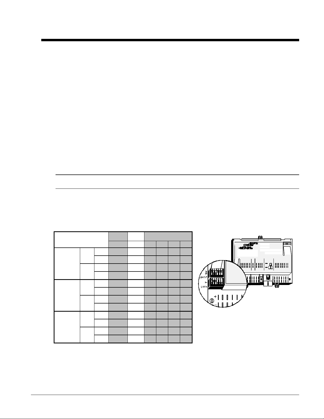
8. Adjust SW1 and SW2 on AI2 for the appropriate number of cooling stages. The AS-UNT330-1/AS-UNT334-1 is
factory set for 6 stages by Johnson Controls. The AS-UNT332-1/AS-UNT336-1 is factory set for 8 stages.
Table 5, Dipswitch Settings
Dipswitch Settings
Factory
Set
Stage
Select
Factory Set
AS-UNT33n-1 AI 1 AI 2 AI 3 AI 4 AI 5 AI 6
AS-UNT330-1 SW2 10 V • • • •
AS-UNT334-1 2 V • •
4 stage
SW1 T •
(set by others) V • • • • •
AS-UNT330-1 SW2 10 V • • • •
AS-UNT334-1 2 V • •
6 Stage
SW1 T • •
(Factory Set) V • • • •
AS-UNT332-1 SW2 10 V • • • • •
AS-UNT336-1 2 V •
8 Stage
SW1 T • •
(Factory Set) V • • • •
Figure 1, Analog Input Switches
C
D
V
5
1
+
A N A LO G I N PU TS
B IN A R Y IN
COM
PW R
I N
2 4V
B IN A R Y CO M
A C
BIN ARY INA NAL OGIN PUTS
BINA RY OUT PUT S
ANAL O G I N PU TS
1 2 3 4 5 6 1 2 3 4
A N A L OG I N P U TS
CO MM ON
B IN A RY OU TP U T
1 2 3 4 5 6 7 8
2 4V A C TO L OA D S
IOM UNT33 5
Page 6
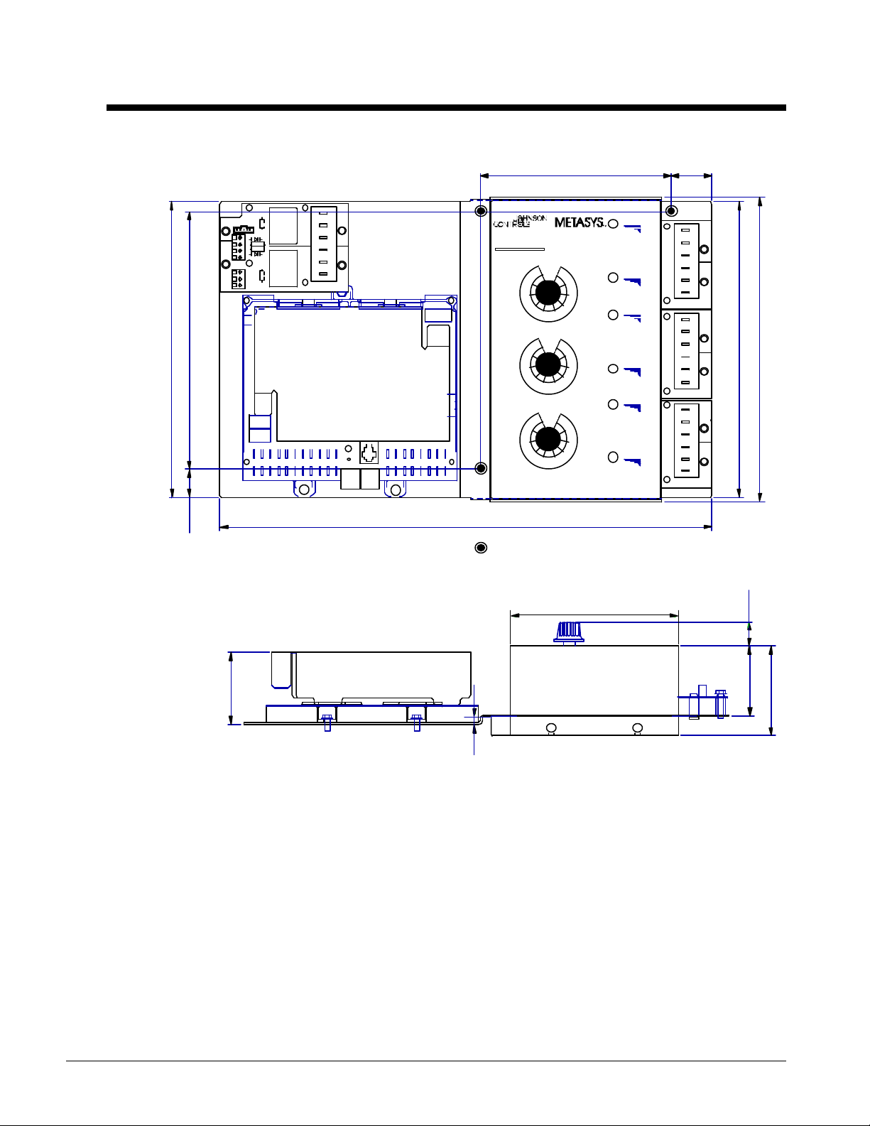
Dimensional Data
Figure 2, Dimensional Data
These relays are for the
7th and 8th stages.
COOL 8
COOL 7
7.78
8.95
SW2
SW1
ANALOG INPUTS BINARY IN
1.245.80
C
B
A
C
B
A
BINARY OUTPUTS
McQuay
RECIPROCATING
CHI LLER CONTROL
SETPOIN T
RESET
CON TROL BAND
COOL 6
COOL 5
COOL 4
COOL 3
COOL 2
COOL 1
C
B
A
C
B
A
C
B
A
C
B
A
C
B
A
C
B
A
8.95
9.23
0.89
14.90
= mounting holes
5.16
2.23
0.74
2.17
2.77
0.25
6 IOM UNT33
Page 7
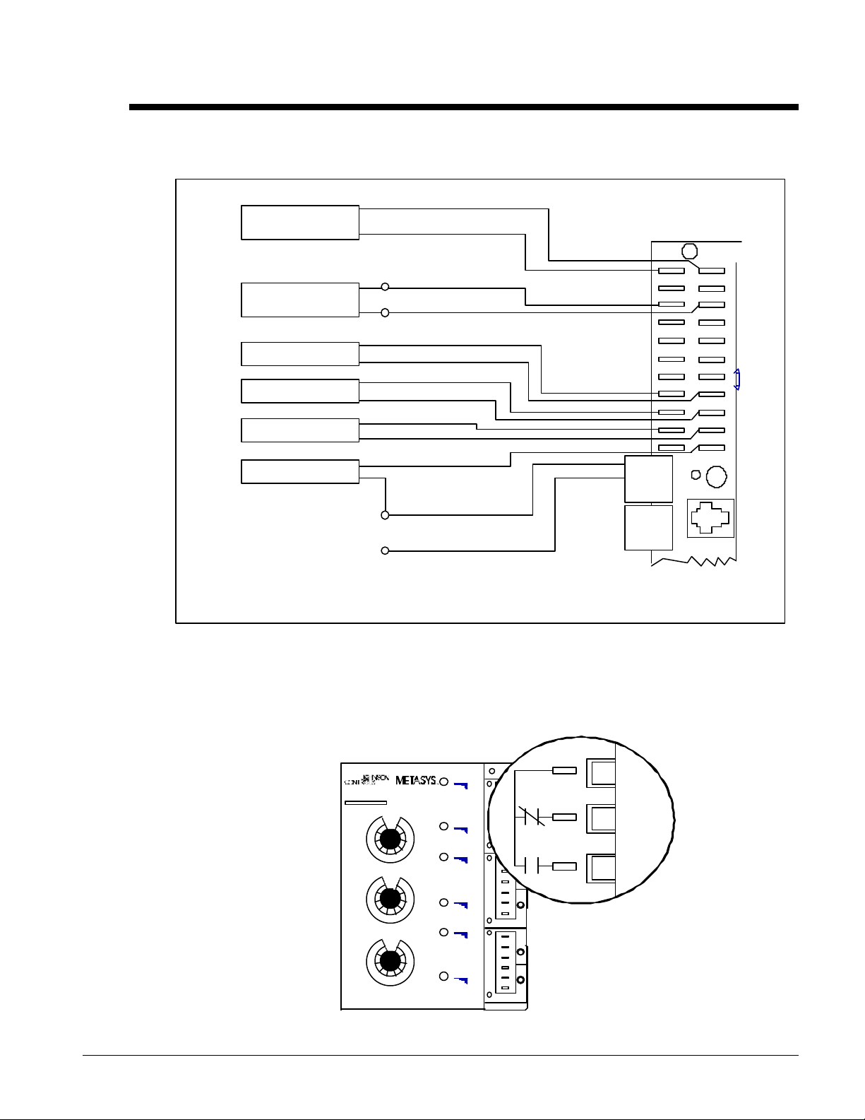
Electrical Data
Sensor for Outdoor, Return Water, or Zone Temperature Reset options are connected to AI-1 and AI-CM.
Figure 3, Wiring Diagram
Note: See Additional Features on page 11 for explanation.
DEMAND LIMIT*
(1)
(2)
0-10 VDC
LEAVING
WATER SENSOR
SHUTDOWN*
COMP LEAD/LAG*
ICE MODE*
FLOW INTERLOCK
Indicates
*
optional
feature.
24VAC
(+)
AI CM
25
26
528
529
(-)
AI CM
AI CM
AI CM
AI CM
AI CM
+15VDC
24VAC
24VAC
24VAC
24VAC
24 C OM Z
VAC B U S
P5 P6
AI1
AI2
AI3
AI4
AI5
AI6
+15VDC
BI1
BI2
BI3
BI4
ANALOG INPUTS BINARY IN
DS
REF N 2 N 2
18
28
512/518
519
- +
P4
(1)
(2) Field connections must be made between TB3-18 and BI-4 for unit to operate.
NNotes:
1. Sensor for Outdoor, Return Water, or Zone Temperature Reset options are connected to Al-1 and Al-CM.
2. Field connections must be made between TB3-18 and Bl-4 for unit to operate.
3. If a time clock is desired, it should be installed between 24 VAC and Bl1. The time clock switch should be installed as follows:
Open to Run and Close to Stop.
Figure 4, Stage Relay Configuration
M cQuay
C ONT ROL BA ND
S ET PO I NT
RE SET
RECIPROCATING
CHILLER CONT ROL
COO L 6
COO L 5
COO L 4
COO L 3
COO L 2
COO L 1
C
B
A
C
B
A
C
B
A
C
B
A
C
B
A
C
B
A
C
B
A
Stage Relays
COM
NC
NO
Note: Refer to Unit Wiring
Diagram for Stage
Wiring.
IOM UNT33 7
Page 8
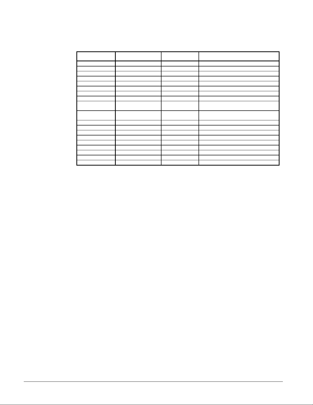
Table 6, Wiring Location Cross Reference
Lead #
512 TB3-18 to TB3-29 (4,6,8 Stages) Not Needed (See Note 1 and 2)
518 TB3-29 to "TR" " TB3-18 to 24 VAC
519 "TR" " Common
522 Ground " Not Needed
524 "7" " Not Needed (See Note 3)
525 TB3-23 to TB3-24 " Not Needed
526 "6" " Not Needed (See Note 3)
527 "P" to "P1" " Not Needed or Zone Terminal Adjust
528 "T" "
529 "T1" "
400 OHM Resister "7" to "8" 4 Stages
600 OHM Resister "7" to "8" 6 Stages See Table 5
800 OHM Resister "7" to "8" 8 Stages
523 Ground 8 Stages Not Needed
535 "1" " Not Needed
536 "2" " Not Needed
537 "3" " Not Needed
538 "4" " Not Needed
539 "5" " Not Needed
Note 1: To install Flow Switch Contacts, connect between TB3-18 and UNT BI-4.
Note 2: To install Time Clock Contacts, connect between TB3-18 and UNT BI-1.
Note 3: The options are as follows. (Option A is standard; options B, C, and D require field download. See "Features Requiring
Configuration and/or Field Adjustment" section for more information):
A. The standard is Demand Limit Input. 0-10VDC signal is required. Connect leads to AI-1 and AI-CM on the
controller.
B. Johnson Controls Outdoor Air Sensor if Outdoor Air Reset is used.
C. Johnson Controls Zone Temperature Sensor if Zone Temperature Reset is used.
D. Johnson Controls Return Water Sensor if Return Water Reset is used.
Honeywell (H/W)
W7100G
Stages
AI-3 (JCI or H/W Leaving Water Sensor. See
Johnson Controls (JCI)
AS-UNT33n-1
appropriate sensor section)
AI-CM (JCI or H/W Leaving Water Sensor.
See appropriate sensor section)
8 IOM UNT33
Page 9

Operation
AS-UNT33n-1
LEAVING
WATER
CONTROL
COOLER
ZONE
TEMPERATURE
OR
OUTDOOR AIR
RESET
(optional)
PUMP
RETURN
WATER SENSOR
(optional)
LEAVING
WATER
SENSOR
COOLING LOAD
RETURN
WATER
LEAVING
WATER
Chiller System
Figure 5, Chiller System
Chiller systems are used to
provide cold water for comfort
cooling or process applications.
Control of the compressor
operation to supply that chilled
water may be initiated by sensing
return water temperature or
leaving water temperature. If
precise control of leaving water
temperature is desired a ASUNT33n-1 controller is
recommended.
LEAVING WATER TEMPERATURE CONTROL
OPERATION
Leaving water temperature will be
controlled to the actual leaving water
setpoint. The actual leaving water setpoint
will be a function of what mode of
operation the controller is in and if a reset
option is used. The Control Band
potentiometer located on the front of the
controller is used to determine the Actual
Leaving Dead Band and Prop Band.
Actual Leaving Dead Band: Control Band
(AI6)/2.
Actual Leaving Prop Band: Dead Band *
Number of Stages.
Example:
Control Band = 4 Deg F
Number of Stages = 6
Dead Band = 4/2 = 2 Deg F
Prop Band = 2 * 6 = 12 Deg F
As the leaving water temperature rises above the actual leaving water setpoint, but within the leaving
dead band, there will be no increase in the Compressor Command. As the leaving water temperature
continues to rise above the Dead Band and into the Prop Band, the Compressor Command will be
increased. When Leaving Integration Gain is used, a Proportional Plus Integral command will be
calculated. As the Compressor Command increases, stages of cooling capacity will be energized.
Minimum on, off, interstage times, and cycles per hour attributes will control the stages.
As the leaving water temperature decreases towards the actual leaving water setpoint, the Compressor
Command will be decreased. Upon reentering the Dead Band, the current Compressor Command will
be maintained. If the Leaving Water Temperature falls below the Actual Leaving Water Setpoint
(using the same Dead Band), the Compressor Command will again start to decrease.
Figure 6, Leaving Water Control
Algorithm Operation
57
PB
47
45
43
LWSP
DB
DB
Control
Band
IOM UNT33 9
Page 10

The "Control Band" is the non-staging area of the control. Anytime the Leaving Water Temperature is
outside of the Control Band limits, staging will occur. Anytime the Leaving Water Temperature is within the
Control Band limits, no staging occurs. As shown in Figure 6, with a 45°F Setpoint and a 4°F Control Band
setting, stages of cooling energize when the Leaving Water is 47°F or higher. Stages de-energize when the
Leaving Water is 43°F or lower (4°F difference). All stages will remain in their current state between 43°F
and 47°F.
AS-UNT33n-1 LED OPERATION
The AS-UNT33n-1 has one LED for each staged output. The LED on the AS-UNT33n-1 will light
simultaneously as that stage relay energizes. If the LED is not lit, the stage is not energized. When a stage
relay energizes, the normally closed contacts open, and the normally open contacts close.
JOHNSON CONTROLS LEAVING WATER SENSOR
Note: Johnson Controls or Honeywell Leaving Water Sensors may be used with the AS-UNT33n-1. Refer
to Table 4, page 4. A description of the Honeywell sensor follows the description of the Johnson Controls
sensor. Accuracy can be determined by measuring sensor resistance and making a comparison to the
temperature and resistance chart. The thin-film nickel sensor has a reference resistance of 1000 ohms at
70°F (21°C) and a change in resistance of approximately 3 ohms/ °F (5 ohms/°C). See Table 7 for resistance
values at selected temperatures.
Table 7, Johnson Controls Leaving Water Sensor, TE-6300-300
Temperature Resistance (Ohms) Temperature Resistance (Ohms)
°° F °° C Nickel °° F °° C Nickel
0 -18 803 70 21 1000
10 -12 830 80 27 1030
20 -7 858 90 32 1060
30 -1 885 100 38 1090
40 4 914 110 43 1121
50 10 942 120 49 1152
60 16 971
HONEYWELL LEAVING WATER SENSOR
The C7173A and C7170A are sensors for use in applications requiring a broad temperature sensing range.
Unlike thermistors, the C7173A and C7170A have a positive temperature coefficient (PTC); resistance
increases as the temperature increases. As shown in Table 8, the resistance curve increases by 4.8 ohms
per degree F temperature rise [8.6 ohms/C].
Resistance in the sensor wiring positively offsets the temperature sensed by 1 degree F every 4.8 ohms
[8.6 ohms/C] of resistance. Use short wire lengths or larger gauge wire when longer lengths are
necessary.
With an accurate thermometer (+/-l°F [.5°C]), measure the fluid temperature at the sensor location,
allowing time for the thermometer to stabilize before reading. Use an ohmmeter to measure the resistance
across the sensor wires. Then verify sensor accuracy with the temperature/resistance values in Table 8.
Table 8, Honeywell Temperature/Resistance Table for C7173A, Leaving Water Sensor
TEMP
°° F
23 3224.8 32 3268.0 41 3311.2 50 3354.4 59 3397.6 68 3440.8 77 3484.0 86 3527.2
24 3229.6 33 3272.8 42 3316.0 51 3359.2 60 3402.4 69 3445.6 78 3488.8 87 3532.0
25 3234.4 34 3277.6 43 3320.8 52 3364.0 61 3407.2 70 3450.4 79 3493.6 88 3536.8
26 3239.2 35 3282.4 44 3325.6 53 3368.8 62 3412.0 71 3455.2 80 3498.4 89 3541.6
27 3244.0 36 3287.2 45 3330.4 54 3373.6 63 3416.8 72 3460.0 81 3503.2 90 3546.4
28 3248.8 37 3292.0 46 3335.2 55 3378.4 64 3421.6 73 3464.8 82 3508.0 91 3551.2
29 3253.6 38 3296.8 47 3340.0 56 3383.2 65 3426.4 74 3469.3 83 3512.8 92 3556.0
30 3258.4 39 3301.6 48 3344.8 57 3388.0 66 3431.2 75 3474.4 84 3517.6 93 3560.8
31 3263.2 40 3306.4 49 3349.6 58 3392.8 67 3436.0 76 3479.2 85 3522.4 94 3565.6
OHMS
TEMP
°° F
OHMS
TEMP
°° F
OHMS
TEMP
°° F
OHMS
TEMP
°° F
OHMS
TEMP
°° F
OHMS
TEMP
°° F
OHMS
TEMP
°° F
OHMS
10 IOM UNT33
Page 11

Additional Features
The following features are also included with the controller algorithm operation. Where there is a
point number specified after the feature name (e.g., AI3), a sensor or contact closure input is required.
LEAVING WATER LOW LIMIT
If the Leaving Water sensor reads a reliable value below an adjustable Leaving Water Low Limit
(LWLL) for more than 3 seconds, the compressor command will be forced to 0% immediately. Once the
Leaving Water Temperature rises above the LWLL by a LWLL Differential (LWLLD), a normal control
sequence will be initiated. Default values are 15°F for the LWLL and 5°F for the LWLLD. Leaving
Water Low Limit will effect compressor commands only.
The default value for the Leaving Low Limit and Differential is adjustable through the Zone Terminal,
HVAC PRO Software, or Johnson Controls Facility Management System.
DEMAND LIMIT INPUT - ANALOG INPUT (AI1)
Demand Limit Input will effect the control strategy as follows. This AI will inversely limit the
Compressor Command for external demand limiting control strategies. As the input goes from 0 - 10
VDC, the Compressor Command will be proportionally limited from 100% to 0%. For example, if the
Demand Limit Input is 5 VDC, the Compressor Command cannot exceed 50%, if 8 VDC is present, the
maximum Compressor Commands will be 20% and so on. The Demand Limiting function can operate
when the control is in the Occupied mode only. Demand Limiting will not occur while in the Ice Mode.
CAUTION: For the Demand Limit Input feature, use only 0-10 VDC input.
COOLING DIAGNOSTICS
The Leaving Water Temperature sensor will be used to determine a drop in Leaving Water
Temperature over time whenever a stage is energized. When a stage is energized, if the Leaving Water
Temperature does not drop by 1°F in five minutes, this is considered a Cooling "Stage Failure." This
failure point can be monitored with the use of a Zone Terminal or Johnson Controls Facility
Management System. Once a Failure has occurred for a particular stage, the alarm can only be cleared
by producing the change in temperature over time or by cycling power.
SHUTDOWN MODE (BI-1)
When shutdown mode is enabled, all stages will be de-energized.
COMPRESSOR LEAD/LAG CONTROL (BI2)
If Lead/Lag Control is desired, a BI (Binary Input) point can be configured to initiate the mode of
operation. When BI2 is open, circuit 1 is the lead. When BI2 is closed, circuit 2 is the lead. The lead
circuit will not change unless all stages are off.
ICE MODE (BI3)
When Ice Mode is enabled, the controller will control Leaving Water Temperature to Ice Mode
Setpoint (default is 23°F). This mode can be enabled or disabled through a BI (Binary Input) hardware
point.
When Ice Mode is enabled, the current Leaving Water Temperature will be compared to the Ice Mode
Setpoint. If it is above the Setpoint, the Compressor Command will be forced to 100%. When the
Leaving Water Temperature drops below the Ice Mode Setpoint, the Compressor Command will be
forced to 0%. These are the only two levels of Compressor Command during Ice Mode. Once the
Compressor Command has fallen to 0% or the Ice Mode is de-activated, the control will return to the
Chiller On or Shutdown Mode. The control will not cycle to maintain an Ice Mode Setpoint.
Whatever triggered Ice Mode must be released before Ice Mode can be triggered again.
The default value for the Ice Mode Setpoint is adjustable through the Zone Terminal, HVAC PRO
Software, or Johnson Controls Facility Management System.
IOM UNT33 11
Page 12

FLOW INTERLOCK INPUT (BI4)
After a transition from Shutdown Mode or Restart Delay the controller will wait 10 seconds for a
verification of Pump Status. If Pump Status is verified during this time, normal control will occur. If
Pump Status is not verified, a "Pump Failure" point will be initiated.
If Pump Status had previously been verified, and then is lost for a period of three seconds, the
Compressor Commands will be forced to zero. If Pump Status is lost for a period of 10 seconds (Pump
Status Delay Timer), the Pump Failure Alarm will be initiated. Once Pump Status is again verified,
normal control will occur and the Alarm will be cleared.
Settings and Adjustments
SETPOINT KNOB
HVAC Applications-Typical Setpoints for HVAC applications range from 42°F to 50°F [5°C to 10°C].
These Setpoints may change due to many factors, including desired space temperature,
required/desired humidity conditions, etc.
CONTROL BAND KNOB
Set for the desired Control Band in accordance with the following formula. Increasing the Control
Band slows down the response of the AS-UNT33n-1, and increases the temperature deviation.
Lowering the Control Band speeds up the response of the AS-UNT33n-1, while decreasing the
temperature deviation from Setpoint.
The Control Band Setpoint should be as narrow as possible without causing hunting or rapid cycling.
If instability, hunting or rapid cycling occurs, widen the Control Band Setpoint. McQuay International
recommends the following formula for calculating the minimum Control Band Setpoint:
Temperature drop across vessel (∆T) at full load/number of stages + .5°F.
Example:
10°F∆T/4 stages of cooling +.5°F = 3°F Control Band.
RESET KNOB
This adjustment adds to the Leaving Water Setpoint, when the control is factory downloaded to
incorporate an Outdoor Air, Zone Temperature, or Return Water Reset function. The standard
application does not include reset; therefore, this Setpoint is disregarded in the algorithm.
12 IOM UNT33
Page 13

System Checkout and Troubleshooting
LWR
B
LWSPOALLOAHLOAR
B
(OALL=OAHL-OARB
)
Equipment needed:
1. Digital Voltmeter 2. Resistor Harness (AS-KIT100-0) included with controller
Table 9, Troubleshooting
Step Action Verification
1 Disconnect power to AS-UNT33n-1.
2 Disconnect compressor and unloader line voltage power. Check for 0 VAC at compressor and unloader contactors or
3 Remove Fast-On for Control Band input from AI6 and
connect resistors as shown.
relays.
AI CM
AI6
+15VDC
4
Set Setpoint knob on AS-UNT33n-1 to 10oF (-12oC).
5 Turn 24 VAC power on to the AS-UNT33n-1. Check for 24 VAC power at AS-UNT33n-1
6 After approximately 70 seconds, all stages will be
7
8 All stages should now be turned off quickly in a
9 Remove power from AS-UNT33n-1 terminals. Check for 0 VAC at compressor and unloader contactors or
10 Reconnect all wiring as originally installed.
11 Reconnect AS-UNT33n-1 power supply, close
energized quickly in an ascending order.
Move Setpoint to 60oF (16oC).
descending order.
compressor disconnects and place Setpoints as desired.
All LED's should be ON. The number of stage LED's illuminated
should correspond to the control model number. If there is a
discrepancy, the stage selection DIP switch (AI2) should be
checked for proper settings. Refer to page 2, Figure 1, Table 5.
All LED's should be OFF.
relays.
System is now operational.
FEATURES REQUIRING FACTORY CONFIGURATION AND/OR FIELD
ADJUSTMENT
RESET OPTIONS
One of the following three reset
options can be selected: Outdoor Air
Reset, Zone Temperature Reset, and
Return Water Reset. The reset
options described below operate on
identical strategies. The main
differences are Setpoints and sensor
locations.
Leaving Water Setpoint and Leaving
Water Reset Band are adjusted using
the Setpoint adjustment knobs on the
front of the AS-UNT33n-1.
Outdoor Air, Zone Temperature, and
Return Water High Limits and their respective Reset Bands are values that can be adjusted by use of a
Zone Terminal, HVAC PRO Software, or Johnson Controls Facility Management System.
Ramping Strategy
Figure 7, Outdoor Air Reset
IOM UNT33 13
Page 14

This ramping strategy applies to all three reset options. When a reset function is used, a Ramping of
sensor
sensor
sensor
sensor
sensor
sensor
sensor
sensor
sensor
Nine sensors wired in
a series/parallel
arrangement for large
areas.
AI1
AI1 COM
the Compressor Command is also used. Two adjustable variables setup the ramp as needed. These
are Ramp Output and Ramp Time.
The Ramp is used to meter the Proportional Command into the Sequencer when conditions don't
require a quick startup of all stages. For example, if the Outdoor Air Temperature (OAT) is at Outdoor
Air Low Limit (OALL), with OALL being equal to Outdoor Air High Limit minus Outdoor Air Reset
Band (OAHL - OARB), the stages do not need to be energized as quickly as they do if the OAT is at
the Outdoor Air High Limit (OAHL). When the OAT is at OAHL, the Proportional Command is fed to
the Sequencer at the same rate as it is calculated. But if the OAT drops below the OAHL, the
Proportional Command is ramped to the Sequencer. This allows for a slower startup of stages.
OUTDOOR AIR RESET
When this option is chosen, an Outdoor Air Temperature (OAT) sensor (AI1) is required.
Four variables are used to setup the reset ramp that calculates the Actual Leaving Water Setpoint.
These are: Leaving Water Setpoint (AI4), Leaving Reset Band (AI5), Outdoor Air High Limit (OAHL),
and Outdoor Air Reset Band (OARB).
As the OAT increases above the Outdoor Air Low Limit (OALL), the Actual Leaving Water Setpoint is
decreased from its Leaving High Limit (Leaving Water Setpoint plus Leaving Reset Band) to the
Leaving Water Setpoint. When OAT reaches the OAHL, the Actual Leaving Water Setpoint equals
the Leaving Water Setpoint (AI4). If the OAT sensor is missing or unreliable, no reset occurs and the
Actual Leaving Water Setpoint equals the Leaving Water Setpoint. If the Leaving Water Sensor (AI3)
becomes unreliable, the compressor command is forced to 0%.
Outdoor Temperature Lockout: If an Outdoor Air Temperature sensor is installed and reliable, the
shutdown mode is initiated whenever it senses, for more than five minutes, an input below the
adjustable Outdoor Temperature Lockout (OTL) Setpoint (45°F).
The default value for this Setpoint is adjustable through the Zone Terminal, HVAC PRO Software, or
Johnson Controls Facility Management System.
ZONE TEMPERATURE RESET
When this option is chosen, a Zone Temperature must be made available to the controller. There are
two ways to do this. The first is through an adjustable Analog Data Float (ADF) point. With the use
of a Johnson Controls Facility Management System, a Zone Temperature or average of multiple Zone
Temperatures can be shared with the controller through the ADF point. The second is through a Zone
Temperature Sensor connected directly to the controller. Regardless of which method is used, the
control strategy is the same.
Four variables are used to setup the reset
ramp that calculates the Actual Leaving
Figure 8, Average Zone Temp. Using TE-6410S-2000
Sensors
Water Setpoint. These are: Leaving Water
Setpoint (AI4), Leaving Reset Band (AI5),
Zone Temperature High Limit (ZTHL), and
Zone Temperature Reset Band (ZTRB).
As the Zone Temperature increases above
the Zone Temperature Low Limit (ZTLL),
the controller decreases the Actual
Leaving Water Setpoint from its Leaving
High Limit (Leaving Water Setpoint plus
Leaving Reset Band) to the Leaving Water
Setpoint. When the Zone Temperature
reaches the ZTHL, the Actual Leaving
Water Setpoint equals the Leaving Water
Setpoint (AI4).
14 IOM UNT33
Page 15

Figure 9, Zone Temperature Reset
(RWLL=RWHL-RWRB
)
If the Zone Temperature sensor is
missing or unreliable, or if there is an
unreliable Zone Temperature value at
the Analog Data Float (ADF) point, no
reset occurs and the Actual Leaving
LWRB
Water Setpoint equals the Leaving
Water Setpoint. If the Leaving Water
Sensor (AI3) becomes unreliable, the
compressor command is forced to 0%.
(ZTLL=ZTHL -Z TRB)
LWSP
ZTLL ZTHL
ZTRB
RETURN WATER RESET
When this option is chosen, a Return Water Temperature (RWT) sensor (AI1) is required. Four
variables are used to setup the reset ramp that calculates the Actual Leaving Water Setpoint. These
are: Leaving Water Setpoint (AI4), Leaving Reset Band (AI5), Return Water High Limit (RWHL), and
Return Water Reset Band (RWRB).
As the RWT increases above the
Return Water Low Limit (RWLL), the
Figure 10, Return Water Reset
controller decreases the Actual Leaving
Water Setpoint from its Leaving High
Limit (Leaving Water Setpoint plus
Leaving Reset Band) to the Leaving
Water Setpoint. When RWT reaches
LWRB
the RWHL, the Actual Leaving Water
Setpoint equals the Leaving Water
Setpoint (AI4). If the RWT sensor is
missing or unreliable, no reset occurs
and the Actual Leaving Water Setpoint
equals the Leaving Water Setpoint. If
LWSP
RWLL RWHL
RWRB
the Leaving Water Sensor (AI3) becomes unreliable, the compressor command is forced to 0%.
When Return Water Reset is chosen, a Fail Smart Logic option is also available. This option works as
follows. If the Leaving Water Sensor (AI3) becomes unreliable, the controller switches from Leaving
Water control to Return Water control. Actual Return Water Setpoint equals Leaving Water Setpoint
(AI4) plus an adjustable Leaving Water Setpoint Offset. This value takes into account the
temperature differential between Leaving and Return water temperatures, which is typically about
10°F. If both the Leaving and Return water sensors are unreliable, the compressor is forced to 0%.
IOM UNT33 15
Page 16

Zone Terminal User's Guide
This user's guide contains step-bystep instructions for using the
Zone Terminal (AS-ZTU330-1) on a
McQuay Reciprocating Chiller (ASUNT33n-1).
This guide assumes you are familiar
with the McQuay Reciprocating
Chiller. This guide contains
examples of the Zone Terminal (ZT)
screen that is standard with the ZT
accessory to the McQuay
Reciprocating Chiller.
USER'S GUIDE
ORGANIZATION
Three major sections describe how
to use the Zone Terminal.
Introduction and Overview:
Explains in general terms the
features and operating modes of
the Zone Terminal.
Getting Started: Includes an explanation of the Keys, Displays, and Symbols on the Zone Terminal.
Also includes an explanation of the Zone Terminal labels and how to install them. In addition, this
section instructs the user about handling Alarm Status and connecting the Zone Terminal.
Making ZT Adjustments: Includes specific instructions for making set point adjustments with the
Zone Terminal.
OVERVIEW OF THE ZONE TERMINAL
The Zone Terminal (ZT) is a hand-held or wall-mounted device that monitors and adjusts your
McQuay Reciprocating Chiller information.
A standard telephone-style jack connects the ZT to the McQuay Reciprocating Chiller controller
directly or through the TE-6410S-2000 Zone Temperature Sensor.
Features
The ZT provides:
• Portability
• Simultaneous monitoring of three different settings or values
• Easy operation with only seven buttons
• Flashing numbers to show which items are ZT adjustable
• Flashing symbols to notify you of alarm conditions
Capabilities
With the ZT, you can:
• Quickly identify a chiller alarm and its location
• Monitor and adjust up to 18 different settings
To familiarize yourself with the ZT, refer to Figure 12.
16 IOM UNT33
Page 17

Figure 11, Zone Terminal Template (See Glossary for Definitions)
Disp lay Item List Warning Signal
Displa y
Button
1
2
3
Mode
Selector
Button
M ode
Selector
Panel
Displa y Indicator Do t
Lvg Water Temp
Demand L imit
Lvg Reset Band
Lvg Cntrl Band
Lvg Dead Band
Lvg Prop Band
Lv g Setp oint
Lvg Low L imit
Low Limit Di ff
Fa ilsoft Set pt
Comp Com mand
Ice Mode S etpt
Cool Diag Time
Cool Diag Temp
Oper at ing Mode Indicat or
MONITOR
ADJUST
TIME SCHEDULE
PASSWORD
ENTER
McQuay Chiller with Demand Limit ON OFF
INSERT 12
R amp Ou tput
Ramp Time
Up/Down Arrow Keys
Door
Disp lay A rea 1 1
Disp lay Ar ea 2 1
Disp lay Ar ea 3 1
On/Off Status
Chiller Off
Cht 2 Lead
Stage 1
Fail Stage 1
Stage 2
Fail Stage 2
Stage 3
Fail Stage 3
Stage 4
Fail Stage 4
Stage 5
Fail Stage 5
Stage 6
Fail Stage 6
Stage 7
Fail Stage 7
Stage 8
Fail Stage 8
ALARM
Alarm Light
OPERATING MODES
Two operating modes are included: Monitor and Adjust.
Monitor Mode
As soon as the ZT is connected, it completes a self-check, and starts up in the Monitor Mode. Monitor Mode lets
you view up to three of chiller settings/sensed values at a time.
To allow you to monitor your system, a clear plastic Insert (factory made and installed) relates the ZT’s output to
your McQuay Reciprocating Chiller system.
You can simultaneously monitor the chiller in three ways:
• Monitor up to three settings/sensed values. A maximum of six items are accessible in each of the three
displays.
• Read the symbols to the right of the display numbers to learn the on/off status of various inputs, outputs,
or modes (| = On status; m = Off status). This provides continuous monitoring of 18 different statuses
(on/off).
• Monitor alarm status–a flashing red alarm light and any flashing symbol ( |, m, s) visually notifies you
when your chiller has an alarm condition.
Adjust Mode
In Adjust Mode, the ZT displays information in each of the three numerical displays. Typically, the displays are set
up so that the relationship between the values can be viewed simultaneously. For example:
IOM UNT33 17
Page 18

Table 10, Displays, Symbols, Keys, and Buttons
DISPLAYS,
SYMBOLS, KEYS,
DESCRIPTION
BUTTONS
Display Button
1, 2, 3
Enter Key
Flashing Numbers
Flashing
ss , mm , ( | )
Mode Selector
Button
On/Off Status
Symbols( | ) for
On/a circle ( mm ) for
Off
Red Alarm Light
Up ( ↑↑) or Down
(↓↓) Arrow Keys
ll
Select the value you want to monitor or
adjust.
Use to commit your changes.
Adjustments are not processed unless
you press Enter.
Appear in Display 1, 2, or 3 to indicate
numbers you can adjust. Numbers that
do not flash are monitor only numbers.
Shows an item is in alarm.
Press this button to select Operating
Modes: Monitor, Adjust, Password,
Time Scheduling. A green Mode
Indicator light moves through the modes.
Observe On/Off conditions of a point in
the HVAC controller with these
symbols. A bar (| ) for On, a circle (m)
for Off. These are always monitor only
items. If the symbol flashes, item is in
alarm.
Flashes anytime a problem exists
regardless of which Operating Mode
you have entered.
Use these keys to adjust a flashing
number.
Appears in the displays, and
corresponds to the item you are
monitoring or adjusting.
Display 1 = Lvg Water Temp
Display 2 = Lvg Setpoint
Display 3 = Comp Command
This operating mode allows you to adjust
any flashing setpoints. Setpoints adjusted
by the ZT remain in effect until you
change them
GETTING STARTED
DISPLAYS, SYMBOLS, KEYS, AND
BUTTONS
The Zone Terminal simultaneously
displays three set points or sensed values.
In addition, flashing symbols indicate
when items are in a state of alarm. The
keys, buttons, displays, and symbols are
explained below.
Figure 12, Installing the Insert
Note: The insert is normally factoryinstalled. These steps are required only if the
insert is not already installed.
To use the ZT, you'll need the plastic label
which is included with your ZT.
Insert
The clear plastic Insert is a custom-made label
unique to your chiller. Use this Insert when
monitoring or adjusting specific items of your
system:
1. With the ZT on a flat surface, press the
white tab with your index finger (Fig. 12).
2. Pull the front cover of the ZT away from
the back and slide the Insert into position.
3. Press the ZT together. With the Insert in
place and the ZT connected, the l in the
top position of each display lines up with
the first word.
18 IOM UNT33
Page 19

CONNECTING THE ZONE TERMINAL
You can wall-mount the ZT, or use it as a portable tool for convenient access to any chiller
information.
Figure 13, Connecting ZT to a Reciprocating
Chiller Controller Using 6 to 8 Pin Cable
6 Pin
Connection
ALARM STATUS
The ZT indicates an alarm as follows
(see Figure 12):
McQuay Reciprocating Controller
Connection
A standard telephone-style jack
connects the ZT to a McQuay Chiller
Controller directly or through a TE6410S-2000 sensor.
AS-UNT3 30-1
+15VD C
CO M MO N
B I N A R Y I NA N A L OG I NP U TS
BI N A R Y COM
BIN ARY INA NALOG INPUTS
1 2 3 4 5 6 1 2 3 4
A N A LOG I N P UT S
Connection
8 Pin
BINARY OUTPUT
CO M
1 2 3 4 5 6 7 8
TO
ZONE
P W R
STAT
I N
24 V
24 V A C TO L OA D S
A C
BIN ARY OUTPUTS
Connect ZT
here.
1 2 3 4 5 6 7 8
OFF
Figure 14, Connecting ZT to a TE-6410S-2000
(METASTAT) Sensor Using Coiled 6 to 6 Pin Cable
• The warning signal (s) flashes to the
right of the Display Indicator dot
( l ) if the system operating values
are in alarm.
• The On/Off Status bar ( | ) or circle
(m) flashes when an On/Off status is
in alarm.
• The red alarm light to the right of the
Mode Selector Panel flashes when
any of the above items are in alarm.
Alarms cannot be cleared with the ZT.
The problem must be corrected by
maintenance or repair of the affected item.
Connect ZT
here.
Open cover.
IOM UNT33 19
Page 20

MAKING ZONE TERMINAL ADJUSTMENTS
Adjusting Control Settings
You can adjust only a flashing number with the ZT. If the number does not flash, that item is a monitor only
item. Adjust Control Settings in Display 1, 2, or 3 as follows:
1. Press the Mode Selector Button until the green Mode Indicator Light moves next to the word Adjust.
2. Press either Display Button 1, 2, or 3 to locate adjustable items, which are indicated by flashing numbers.
If you continue pressing the display buttons, the dot ( l ) in each display changes positions and the
corresponding number appears.
3. Press the Up ( - ) or Down ( ¯ ) Arrow key until you reach the number you want to enter. If you hold down the
Up ( - ) or Down ( ¯ ) Arrow keys, you can speed through the numbers more quickly.
Press Enter. After you press Enter, the numbers stop flashing for a few seconds. This pause tells you the ZT
has processed your adjustment.
4. Press any of the Display Buttons to make other adjustments, and repeat Steps 2 and 3.
Note: Some adjustable set points have high and low limits beyond which you cannot adjust them.
Adjustable Points
The following McQuay Reciprocating Chiller points are adjustable by the Zone Terminal.
Table 11, Adjustable points
FULL POINT NAME TEMPLATE NAME
Leaving Low Limit Lvg Low Limit
Low Limit Differential Low Limit Diff
Ice Mode Setpoint Ice Mode Setpt
Failsoft Setpoint Failsoft Setpt
Cool Diagnostic Time Cool Diag Time
Cool Diagnostic Temperature Cool Diag Temp
Note: Refer to the Glossary (next section) for definitions
20 IOM UNT33
Page 21

Zone Terminal Glossary
Chiller Off
A "|" indicates the chiller is in Shutdown Mode.
Ckt 2 Lead
A "|" indicates circuit 2 is lead circuit.
Comp Command
The Compressor Command is the percent of Chiller capacity that is required.
Cool Diag Time/Temp
When a compressor stage is started, the controller must sense the Leaving Water Temperature change (Cool Diag
Temp) within a time span (Cool Diag Time) or a Full Stage Alarm will occur.
Demand Limit
The percentage by which the maximum Compressor Command of 100% is reduced.
Failsoft Setpt
If the adjustable Leaving Water Setpoint setting ion the face of the controller fails, the failsoft setpoint is the value
the Leaving Water Setpoint defaults to.
Fail Stage n
A "|" indicates a possible fault condition exists.
Ice Mode Setpt
The Leaving Water Temperature at which Ice Mode operation is concluded.
Low Limit Diff
The amount the Leaving Water Temperature has to increase above the Leaving Water Low Limit to allow
compressors to restart.
Lvg Cntrl Band
The Leaving Water Control Band is centered around the Leaving Water Setpoint. When the Leaving Water
Temperature is within the Leaving Water Control Band, stages will not be energized or de-energized.
Lvg Dead Band
The Leaving Water Dead Band is one half of the Leaving Water Control Band.
Lvg Low Limit
When Leaving Water reaches the Leaving Water Low Limit, the Compressor Command will be forced to 0%.
Lvg Prop Band
The Leaving Water Proportional Band is the Leaving Water Dead Band multiplied by the number of stages.
Lvg Reset Band
When reset functions are used, the Leaving Water Reset Band is the amount the Leaving Water Setpoint is
automatically increased. The Leaving Water Reset Band adjustment can be found on the face of the controller.
Lvg Setpoint
The Leaving Water Temperature setting by which the controller will control to. The Leaving Water Setpoint
adjustment can be found on the face of the controller.
Lvg Water Temp
The temperature of the leaving water from a McQuay Reciprocating Chiller.
Ramp Output/Time
Ramp Output and Time are used to determine softstart. They define the percentage rate of increase for the
Compressor Command.
Stage n
A "|" indicates stage is energized.
IOM UNT33 21
Page 22

22 IOM UNT33
Page 23

Page 24

P.O. Box 2510, Staunton, Virginia 24402 USA • (800) 432-1342 • www.mcquay.com
 Loading...