

Page 1
Product Manual
Air-Cooled Reciprocating Water Chillers
ALR 110F through 150F
110 to 150 Tons, 380 to 525 kW
R-22
60 Hertz
PM ALR2-3
Group: Chiller
Date: August 2000
Supersedes: PM ALR2-2
© 2000 McQuay International
Page 2
Table of Contents
Introduction...................................................................................................................3
Design Advantages.........................................................................................................4
Selection Procedure.......................................................................................................9
Performance Adjustment Factors..................................................................................10
Performance Data........................................................................................................12
Part Load Data............................................................................................................14
Pressure Drops............................................................................................................15
Sound Data..................................................................................................................16
Electrical Data..............................................................................................................20
Physical Data...............................................................................................................27
Dimensional Data.........................................................................................................29
Installation and Application...........................................................................................30
Remote Evaporator......................................................................................................40
Dimensions, Remote Evaporator...................................................................................42
Optional Features.........................................................................................................43
Specifications...............................................................................................................45
Remote evaporator arrangement
is not in ARI certification
Our facility is ISO Certified
"McQuay" is a registered trademark of McQuay International
"Information covers McQuay International products at the time of publication and we reserve the right to make changes in
design and construction at anytime without notice"
2 ALR 110F – 150F Product Manual ALR2-3
1997 McQuay International
Page 3
Introduction
McQuay International offers a complete line of air-cooled chillers from 10 to 425 tons (35 to
1500 kW) utilizing scroll, reciprocating, and rotary screw compressors.
The McQuay ALR reciprocating compressor, air-cooled chiller is a product of the McQuay
commitment to offer reliable, energy efficient equipment design. A design approach
incorporating high quality compressors and uncompromised operating efficiency. McQuay
International will provide its customers with products and services that meet or exceed their
expectations in terms of quality, availability and competitiveness.
Efficiency
• Cross-circuit compressor unloading
• Copeland DISCUS compressors
• High efficiency lanced fin condenser coils
ARI 550/590-98 Certified
FEATURES-BENEFITS
Reliability
• Rugged compressor design
• Factory installed operating and safety controls
• Factory run tested with water hookup
• Code and agency approval
Flexibility
• Complete factory assembly
• Large size availability in small capacity increments
• A wide variety of field and factory installed options
• Available with remote evaporator (R-22 only)
Serviceability
• Semi-hermetic compressors
• Suction and discharge service valves
• Dual refrigerant circuits
Product Manual ALR2-3 ALR 110F – 150F 3
Page 4

Design Advantages
Construction
The ALR 110F through 150F are factory assembled and mounted on a rugged steel channel base. The
channel base distributes the unit weight for low roof loading. Lifting holes in the base simplify
rigging. Optional wire mesh base guards are available to prevent intrusion to the area under the coils.
The units pass the ASTM B117 500 hour salt spray test.
Compressors
ALR 110F through 150F chillers use Copeland DISCUS semi-hermetic compressors. These
compressors are designed for Refrigerant 22 and the high loading associated with air-cooled
applications.
Semi-hermetic, 1750 rpm induction type motors are used. The motors are refrigerant-gas cooled.
Solid-state modules in the motor terminal box respond to temperature sensors imbedded in all three
motor windings, providing inherent thermal overload protection for all run and start conditions.
The compressor housing is constructed from closed grained, high nickel content, alloy cast-iron with
no bolted joint between the motor and compressor. The housing includes a cast-iron cylinder head
and stator cover, and a crankcase oil sightglass. A suction strainer built into the compressor in the gas
stream between the suction service valve and the motor, filters out foreign and abrasive particles. An
internal relief valve relieves discharge pressure to the suction side for safety protection at high
compression ratios as required by ANSI/ASHRAE 15 Safety Code.
Main bearings are solid cast bronze insert type with oversized bearing area that result in ultra-low
bearing loading.
The crankshaft is die-forged, high strength iron alloy with integral counterweights, statically and
dynamically balanced for smooth operation.
Connecting rods are lightweight aluminum with integral bearing surfaces on the crankshaft and piston
ends. Pistons are close grain cast iron with oil and compression rings. Piston pins are full floating
type for long life.
Compressors have a forced-feed lubrication system with positive oil displacement, a reversible oil
pump, and an operating oil charge. The pump feeds oil through rifle drilled passages in the crankshaft
to all bearing surfaces. Magnetic plugs trap magnetic particles that enter the crankcase. The oil
supply filters through a large area oil strainer. A crankcase heater minimizes oil dilution by refrigerant
at start-up.
Condenser Coils
Condenser coils have internally enhanced seamless copper tubes arranged in a staggered row pattern.
The tubes are mechanically expanded into McQuay lanced and rippled aluminum fins with full fin
collars. See the Application Section of this manual for optional corrosive resistant fin material and
coatings. An integral subcooler circuit provides subcooling to effectively eliminate the possibility of
liquid flashing. Vinyl coated wire mesh coil guards for fin protection are supplied as standard.
Condenser Fans and Motors
Multiple direct drive propeller fans operate in formed bell shaped orifices at low tip speeds for
maximum efficiency and minimum noise and vibration. A heavy-gauge close mesh fan guard protects
each fan.
Each condenser fan motor is heavy-duty, 3-phase with permanently lubricated ball bearings and
inherent overload protection.
4 ALR 110F – 150F Product Manual ALR2-3
Page 5

Hot Gas Mufflers
Hot gas discharge line mufflers are installed in each refrigerant circuit to reduce the overall sound
levels.
Evaporator
The evaporator is direct expansion, shell-and-tube type with water flowing in the baffled shell side and
refrigerant flowing through the tubes. Two independent refrigerant circuits within the evaporator
serve the unit's dual refrigerant circuits.
The evaporator has a carbon steel shell and seamless high efficiency copper tubes roller expanded
into a carbon steel tube sheet.
Refrigerant heads are carbon steel with multi-pass baffles to ensure oil return and are removable to
permit access to the tubes from either end. For water removal and venting, 1/2" (12.7mm) vent and
drain plugs are provided on the top and bottom of the shell.
The evaporator is wrapped with an electric resistance heater cable and insulated with 3/4" (19mm)
thick vinyl nitrate polymer sheet insulation, protecting against water freeze-up at ambient air
temperatures to -20°F (-29°C). An ambient thermostat controls the heater cable.
The insulation has a K factor of 0.28 at 75°F (23°C). The fitted and cemented in place insulation is
painted with a resilient vinyl base paint to resist cracking.
The tube side maximum working pressure is 315 psig (2170 kPa). The water side working pressure is
152 psig (1047 kPa). Each evaporator is designed, constructed, inspected, and stamped according to
the requirements of the ASME Boiler and Pressure Vessel Code.
NOTE : A chilled water pump starter interlock, water flow switch or both, must be field installed to
protect against evaporator freeze-up under low water flow conditions.
Electrical Control Center
Operating controls, safety controls, control transformer, and motor starting equipment is factory wired,
operationally tested, and ready for service. All centrally located controls are in a weatherproof,
hinged control center with key-locked doors. Panel access doors include steel rod door retainers to
secure the doors when open.
A fixed 5-minute, solid-state lockout timer delays compressor restart after a safety cutout, power
interruption, or thermostat cycling.
Power connection to the unit can be single-point or multiple-point. Single point is usually more
economical. Multiple point provides separate power for each of two compressor circuits plus a third
circuit for the fans and control power.
Part winding start is standard on 208 and 230 volt compressor motors. Across-the-line start is
standard on 380, 460 and 575 volts.
Circuit Breakers
Circuit breakers are factory installed, providing unit compressor short circuit protection.
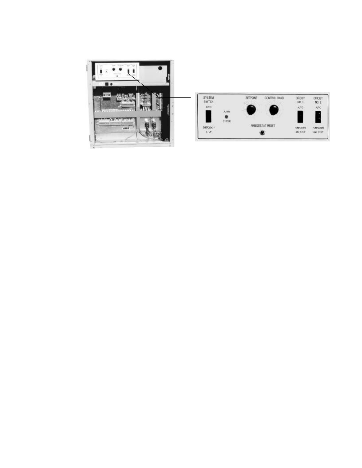
Standard UNT Controller
This microprocessor based control accomplishes unit capacity control by staging compressors and by
cylinder unloading based on leaving chilled water temperature. Setpoint and control band are easily
field adjusted. Anti-cycling and stage delay timers are included. Safety controls include low
refrigerant pressure, low evaporator flow (field installed flow switch), low oil pressure, and sensor
failures. Outside air temperature sensor is standard. Reset options are; outside air, return water,
remote reset, demand limit, zone temperature reset. The optional Zone Terminal and Display control is
required to adjust the reset setpoints.
Product Manual ALR2-3 ALR 110F – 150F 5
Page 6
Thirty feet of sensor cable is included, rolled up in the control panel, on remote evaporator models.
The cable can be field spliced for a total run not to exceed 75 feet.
Figure 1, Standard UNT Controller
UNT with Optional Zone Terminal and Display
The optional Zone Terminal and Display can be mounted in the chiller control panel or remotely
located providing monitoring and adjusting of certain functions.
• Monitoring
• Monitor up to three setting or sensed values
• Monitor 18 different on/off inputs
• Monitor alarm status via a flashing alarm light and flashing symbol
• Adjusting allows adjustment of any flashing set points, three at a time, typically set up so that the
relationship between values can be viewed simultaneously. For example:
• Display 1 = Lvg Water temp, Display 2 = Lvg Water SP, Display 3 = % Unit Load
6 ALR 110F – 150F Product Manual ALR2-3
Page 7

Figure 2, Zone Terminal Configuration
Display Item List
Display Indicator Dot
Warning Signal
On/Off Status
Display
Button 1
Mode
Selector
Button
Mode
Selector
Panel
Door
2
3
Mc Quay AGZ/AG R Global Chiller
Lvg Water Temp
Evap Pres #1
Evap Pres #2
OA/AI3 Input
OA/AI3 HiLimSP
OA/AI3 ResetSP
Lvg Water SP
LvgWtr RBnd SP
Contrl Band SP
Actual Lvg SP
Unoccpd Lvg SP
OA Lockout SP
% Unit Load
Lvg Low Lim SP
SoftSta Capcty
SoftStart Time
Cir #1 Starts
Cir #2 Starts
Operating Mode Indicator
MONI TOR
ADJU ST
TIME SCH EDU LE
PASS WORD
ENTER
INSERT 10
Display Area 11
Display Area 21
Display Area 31
Up/Down Arrow Keys
ON OFF
Occupied
Flow Failure
OA Lockout
Cir#2Lead=On
Pmp/Stp #1=0
Pmp/Stp #2=0
Solenoid #1
Solenoid #2
Frzstat#1Alm
Frzstat#2Alm
MinLowPres#1
MinLowPres#2
Compressor 1
Compressor 2
Stage 3
Stage 4
Stage 5 Opt.
Stage 6 Opt.
ALARM
Alarm Light
AGZ-AGR
Optional MicroTech Control
The exclusive MicroTech microprocessor control is common throughout McQuay equipment. The
interface is a 12 key keypad and 2-line, 32 character backlit liquid crystal display. The MicroTech
continuously performs self-diagnostic checks on all system temperatures, pressures, and safeties, and
will automatically shut down a circuit or the entire unit if a fault condition occurs. The cause, time,
and date of the occurrence is recorded and can be displayed. The seven previous incidents are kept
in memory for service reference.
If a fault occurs, the controller takes preventive measures in an effort to keep the unit operating;
staging down capacity, activating a pre-alarm signal, and automatically switching to the alarm menu on
the display. Pre-alarms are self-clearing when the fault condition is no longer present.
Critical shutdown alarms such as high condenser pressure (with mechanical back up), freeze
protection, oil pressure (with mechanical back up), and low evaporator pressure are manual reset and
must be cleared at the keypad to resume operation.
Choose the MicroTech control and Open Protocol options to interface with virtually any building
management system and perform remote monitoring and control by hard wiring or modem. A nominal
site license fee is required for a Building Automation System (BAS) interface.
A single chiller can connect directly to the BAS. Two or more units will require an Open Protocol
Panel (OPM) for connection.
Thirty feet of sensor cable is included, rolled up in the control panel, on remote evaporator models.
The cable can be field spliced for a total run not to exceed 75 feet.
Product Manual ALR2-3 ALR 110F – 150F 7
Page 8
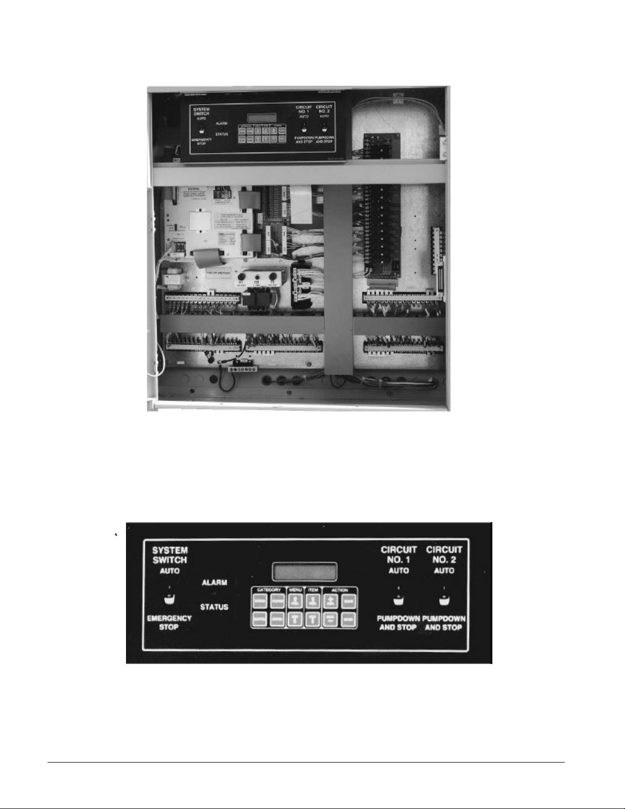
Figure 3, Optional MicroTech Control Panel
Figure 4, MicroTech Control
8 ALR 110F – 150F Product Manual ALR2-3
Page 9

Selection Procedure
Selection Procedure
Table 4 (R-22) covers the range of leaving evaporator water temperatures and ambient air temperatures
encompassed under ARI 550/590-98. Table 5 covers SI units. The tables are based on a 10 degree F
temperature drop through the evaporator (2.4 gpm/ton). Adjustment factors for applications having
other than a 10 degree F drop can be found in Table 3. The minimum leaving chilled water temperature
setpoint without glycol is 40°F. For brine selections, see Table 1 for ethylene glycol or Table 2 for
propylene glycol adjustment factors. Ratings are based on a 0.0001 fouling factor in the evaporator at
sea level operation. See Table 3 for other fouling factors, derates for different delta-Ts, or altitude
correction factors. For applications outside the catalog ratings contact your local McQuay sales
representative.
Selection example
Given:
R-22, 110 tons minimum.
95°F ambient temperature
264 gpm, 54°F - 44°F chilled water
0.0001 evaporator fouling factor
1. From Performance Table 4, an ALR 110F at the given conditions will produce 110.9 tons with a
compressor kW input of 120.6 and a unit EER of 9.8
2. Use the following formula (for water) to calculate missing elements:
tons°∆×
= gpm
24
FT
3. Determine the evaporator pressure drop. Using Figure 5, enter at 264 gpm and follow up to the
ALR 110 line intersect. Read horizontally to obtain an evaporator pressure drop of 14.3 feet of
water.
Selection example using ethylene glycol
Given:
R-22, 105 tons minimum
95°F ambient air temperature
54°F - 44°F chilled water temperature
0.0001 evaporator fouling factor
Protect from freezing down to 0°F
1. From Table 1, select an ethylene glycol concentration of 40% to protect against freezing at 0°F.
2. At 40% glycol: Capacity = 0.961, kW = 0.976,
flow = 1.121, pressure drop = 1.263
3. Consider the ALR 110F and correct with 40% ethylene glycol factors.
4. Correct capacity = 0.961 x 110.9 tons = 106.6 tons
5. Correct compressor kW = 0.976 x 120.6 kW = 119.5 kW
6. Correct chilled water flow for flow required for the glycol solution:
246.106
tons°∆×
= capacity) corrected(at flowWater
10
FT
Glycol flow (at 40% solution) = 1.121 x 256 gpm = 286.8 gpm
gpm 256 =
Determine the evaporator pressure drop. Using Figure 5, enter at 256 gpm (water flow rate) and follow
up to the ALR 110F line intersect. Read horizontally to obtain an evaporator pressure drop of 13.6
feet. The pressure drop for 40% solution = 1.263 x 13.6 feet = 17.2 feet of water
Product Manual ALR2-3 ALR 110F – 150F 9
Page 10
Performance Adjustment Factors
Ethylene and Propylene Glycol Factors
ALR units can operate with a leaving chilled fluid temperature range of 20°F (-6°C) to 60°F (10°C). A
glycol solution is required when leaving chilled fluid temperature is below 40°F (4.6°C). The use of
glycol will reduce the performance of the unit depending on concentration. Manufacturers do not
recommend the use of solutions of less than 25 percent due to the possibility of insufficient corrosion
protection.
Altitude Correction Factors
Performance tables are based at sea level. Elevations other than sea level affect the performance of the
unit. The decreased air density will reduce condenser capacity, consequently reducing the unit's
performance. For performance at elevations other than sea level refer to Table 3.
Evaporator Temperature Drop Factors
Performance tables are based on a 10 degree F (5.5 degree C) temperature drop through the evaporator.
Adjustment factors for applications having temperature drops from 6 degree F to 16 degree F (3.3
degree C to 8.9 degree C) are in Table 3. Temperature drops outside this range may affect the control
system's capability to maintain acceptable control and are not recommended.
The maximum water temperature that can be circulated through the evaporator in a non-operating
mode is 100°F (37.8°C).
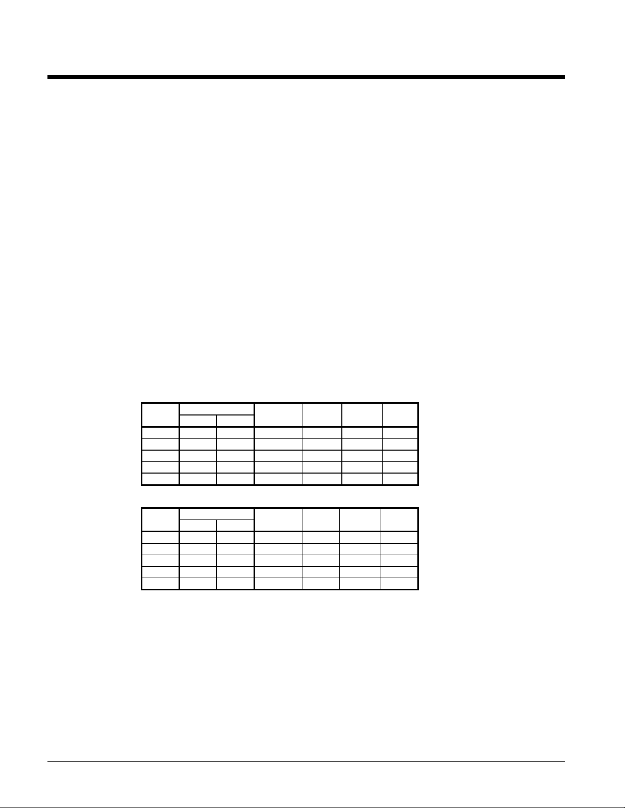
Table 1, Ethylene Glycol
Freeze Point%
E.G.
10 26 -3 0.991 0.996 1.013 1.070
20 18 -8 0.982 0.992 1.040 1.129
30 7 -14 0.972 0.986 1.074 1.181
40 -7 -22 0.961 0.976 1.121 1.263
50 -28 -33 0.946 0.966 1.178 1.308
Table 2, Propylene Glycol
P.G.
10 26 -3 0.987 0.992 1.010 1.068
20 19 -7 0.975 0.985 1.028 1.147
30 9 -13 0.962 0.978 1.050 1.248
40 -5 -21 0.946 0.971 1.078 1.366
50 -27 -33 0.929 0.965 1.116 1.481
Units operating with glycol solutions are not included in the ARI
Certification Program.
°F °C
Freeze Point%
°F °C
Capacity Power Flow PD
Capacity Power Flow PD
Fouling factor
Performance tables are based on a fouling factor of 0.0001 ft2 x hr x °F/Btu (0.0176 m2 x °C/kW) per
ARI Standard 550/590-98. As fouling is increased, performance decreases. Refer to Table 3 for
performance at other than 0.0001 (.0176) fouling factor.
Foreign matter in the chilled water system will adversely affect the heat transfer capability of the
evaporator, and could increase the pressure drop and reduce the water flow. To ensure optimum unit
operation, proper water treatment must be maintained.
10 ALR 110F – 150F Product Manual ALR2-3
Page 11
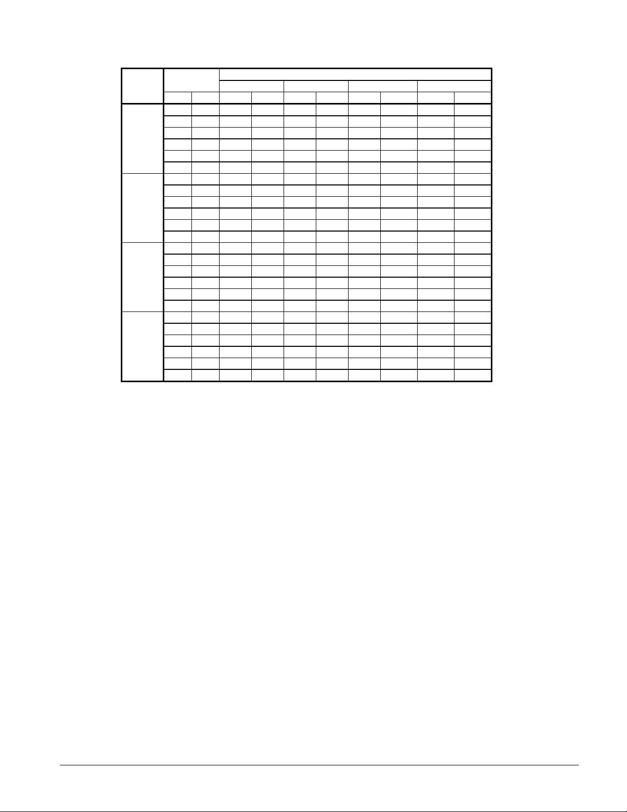
Table 3, Capacity and Power Derates
Chilled Water
SEA
LEVEL
2000 feet
(610 m)
4000 feet
(1220 m)
6000 feet
(1830 m)
Delta-T
°F °C Cap. Power Cap. Power Cap. Power Cap. Power
6 3.3 0.992 0.995 0.985 0.993 0.962 0.986 0.919 0.972
8 4.4 0.995 0.997 0.988 0.995 0.965 0.988 0.922 0.974
10 5.6 1.000 1.000 0.993 0.998 0.970 0.991 0.927 0.977
12 6.7 1.005 1.002 0.998 1.000 0.975 0.993 0.932 0.979
14 6.8 1.010 1.005 1.003 1.003 0.980 0.996 0.936 0.982
16 8.9 1.014 1.007 1.007 1.005 0.984 0.998 0.940 0.984
6 3.3 0.978 1.005 0.971 1.003 0.949 0.996 0.906 0.982
8 4.4 0.982 1.007 0.975 1.005 0.953 0.998 0.910 0.984
10 5.6 0.986 1.009 0.979 1.007 0.956 1.000 0.914 0.986
12 6.7 0.992 1.011 0.985 1.009 0.962 1.002 0.919 0.988
14 6.8 0.997 1.014 0.990 1.012 0.967 1.005 0.924 0.991
16 8.9 1.000 1.016 0.993 1.014 0.970 1.007 0.927 0.993
6 3.3 0.966 1.016 0.959 1.014 0.937 1.007 0.895 0.993
8 4.4 0.969 1.018 0.962 1.016 0.940 1.009 0.898 0.995
10 5.6 0.973 1.021 0.966 1.019 0.944 1.012 0.902 0.998
12 6.7 0.978 1.025 0.971 1.023 0.949 1.016 0.906 1.002
14 6.8 0.982 1.027 0.975 1.025 0.953 1.018 0.910 1.004
16 8.9 0.986 1.028 0.979 1.026 0.956 1.019 0.914 1.005
6 3.3 0.953 1.025 0.946 1.023 0.924 1.016 0.883 1.002
8 4.4 0.955 1.028 0.948 1.026 0.926 1.019 0.885 1.005
10 5.6 0.959 1.031 0.952 1.029 0.930 1.022 0.889 1.008
12 6.7 0.963 1.034 0.956 1.032 0.934 1.024 0.893 1.011
14 6.8 0.968 1.036 0.961 1.034 0.939 1.026 0.897 1.013
16 8.9 0.972 1.037 0.965 1.035 0.943 1.027 0.901 1.014
0.0001 (0.0176) 0.00025 (0.044) 0.00075 (0.132) 0.00175 (0.308)ALTITUDE
NOTE: Contact McQuay sales office for applications above 6,000 feet.
Fouling Factor
Product Manual ALR2-3 ALR 110F – 150F 11
Page 12
Performance Data
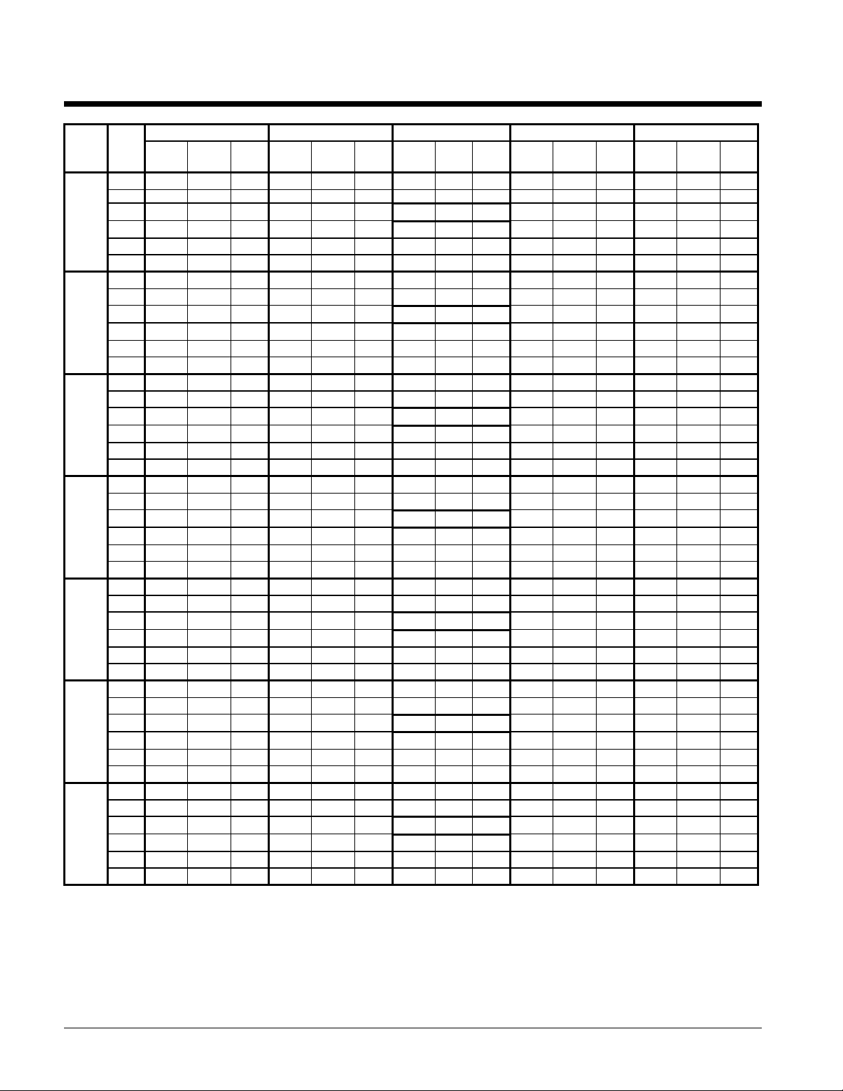
Table 4, ALR 110F - 150F, R-22, I-P Units
ALR
LWT
SIZE
110F
120F
130F
135F
140F
145F
150F
NOTES:
1. Bold box areas certified in accordance with ARI Standard 550/590-98.
2. Ratings based on HCFC-22, evaporator fouling of 0.0001, evaporator temperature drop of 10°F and sea level altitude.
3. For 208V units multiply capacity and EER by 0.98. For units with SpeedTrol option multiply capacity and EER by 0.99.
4. Interpolation is allowed; extrapolation is not permitted. Consult McQuay for performance outside the cataloged ratings.
5. kWi input is for compressors only. EER is for the entire unit, including compressors, fan motors and control power.
6. For LWT of 40°F and below please refer to application considerations for reciprocating chillers located in this manual.
(°F)
40.0 115.8 99.7 12.1 109.6 108.3 10.8 103.4 116.7 9.4 96.8 125.1 8.4 90.9 133.5 7.3
42.0 118.9 101.0 12.4 113.3 110.0 10.9 106.9 118.6 9.6 100.3 127.4 8.5 94.0 136.1 7.5
44.0 123.4 102.4 12.6 116.9 111.6 11.1
46.0 127.5 103.7 12.9 120.8 113.2 11.3 114.5 122.5 10.0 107.2 131.8 8.8 100.3 141.2 7.7
48.0 130.8 104.9 13.2 123.9 114.8 11.6 117.5 124.4 10.1 110.0 133.9 8.9 103.0 143.8 7.9
50.0 136.0 106.2 13.5 129.1 116.5 11.8 122.0 126.2 10.4 114.7 136.2 9.1 107.5 146.4 8.0
40.0 127.7 106.9 11.8 120.9 116.1 10.5 114.1 125.1 9.2 106.7 134.1 8.2 100.2 143.1 7.2
42.0 131.2 108.3 12.1 124.9 117.9 10.7 117.8 127.2 9.4 110.6 136.6 8.3 103.7 145.9 7.3
44.0 136.1 109.7 12.3 129.0 119.7 10.9
46.0 140.6 111.1 12.6 133.2 121.3 11.1 126.3 131.3 9.8 118.2 141.3 8.6 110.6 151.3 7.6
48.0 144.2 112.4 12.9 136.7 123.0 11.3 129.6 133.4 9.9 121.3 143.6 8.7 113.6 154.2 7.7
50.0 150.0 113.9 13.2 142.4 124.8 11.6 134.6 135.3 10.1 126.5 146.0 8.9 118.6 156.9 7.8
40.0 135.4 117.1 12.2 128.2 127.2 10.8 120.9 137.1 9.5 113.1 147.0 8.4 106.3 156.8 7.4
42.0 139.1 118.7 12.4 132.5 129.1 11.0 124.9 139.3 9.6 117.3 149.7 8.5 109.9 159.9 7.5
44.0 144.2 120.2 12.5 136.7 131.1 11.0
46.0 149.0 121.8 12.8 141.3 133.0 11.2 133.9 143.9 9.9 125.3 154.8 8.7 117.3 165.8 7.6
48.0 152.9 123.2 13.0 144.9 134.8 11.4 137.4 146.1 10.0 128.6 157.3 8.8 120.4 168.9 7.8
50.0 159.0 124.7 13.3 151.0 136.8 11.7 142.7 148.3 10.2 134.1 160.0 9.0 125.7 171.9 7.9
40.0 139.7 123.8 11.8 132.2 134.4 10.5 124.7 144.9 9.2 116.7 155.4 8.2 109.6 165.7 7.2
42.0 143.5 125.4 12.1 136.6 136.5 10.7 128.9 147.3 9.4 121.0 158.2 8.3 113.4 169.0 7.3
44.0 148.8 127.1 12.3 141.1 138.6 10.8
46.0 153.8 128.7 12.6 145.7 140.6 11.1 138.1 152.1 9.8 129.3 163.6 8.6 121.0 175.3 7.6
48.0 157.8 130.2 12.9 149.5 142.5 11.3 141.7 154.5 9.9 132.6 166.3 8.7 124.2 178.6 7.7
50.0 164.0 131.9 13.2 155.8 144.6 11.5 147.2 156.7 10.1 138.4 169.2 8.9 129.7 181.7 7.8
40.0 145.9 129.9 11.6 138.1 141.1 10.3 130.3 152.1 9.0 121.9 163.1 8.0 114.5 173.9 7.0
42.0 149.9 131.7 11.8 142.7 143.3 10.5 134.6 154.6 9.2 126.4 166.1 8.1 118.4 177.4 7.1
44.0 155.4 133.4 12.3 147.3 145.5 10.8
46.0 160.6 135.1 12.6 152.2 147.5 11.1 144.3 159.6 9.8 135.1 171.7 8.6 126.4 184.0 7.6
48.0 164.8 136.7 12.9 156.1 149.6 11.3 148.0 162.1 9.9 138.5 174.5 8.7 129.7 187.4 7.7
50.0 171.4 138.4 13.2 162.7 151.8 11.5 153.8 164.5 10.1 144.6 177.5 8.9 135.5 190.7 7.8
40.0 149.7 132.5 11.9 141.6 143.9 10.6 133.6 155.1 9.3 125.0 166.3 8.2 117.4 177.3 7.2
42.0 153.7 134.2 12.2 146.4 146.1 10.7 138.1 157.6 9.4 129.6 169.3 8.4 121.4 180.9 7.3
44.0 159.4 136.0 12.4 151.1 148.3 10.9
46.0 164.7 137.8 12.7 156.1 150.4 11.1 147.9 162.8 9.8 138.5 175.1 8.6 129.6 187.6 7.6
48.0 169.0 139.4 13.0 160.1 152.5 11.4 151.8 165.3 9.9 142.1 178.0 8.8 133.0 191.1 7.7
50.0 175.7 141.1 13.2 166.8 154.7 11.6 157.7 167.7 10.2 148.2 181.0 8.9 138.9 194.5 7.9
40.0 156.2 138.7 11.9 147.8 150.6 10.6 139.5 162.3 9.3 130.5 174.0 8.2 122.6 185.6 7.2
42.0 160.4 140.5 12.2 152.8 152.9 10.7 144.1 165.0 9.4 135.3 177.2 8.4 126.8 189.3 7.3
44.0 166.4 142.3 12.4 157.7 155.3 10.9
46.0 171.9 144.2 12.7 162.9 157.4 11.1 154.4 170.3 9.8 144.5 183.2 8.6 135.3 196.3 7.6
48.0 176.4 145.9 13.0 167.1 159.6 11.4 158.4 173.0 9.9 148.3 186.3 8.8 138.9 200.0 7.7
50.0 183.4 147.7 13.2 174.1 162.0 11.6 164.6 175.5 10.2 154.7 189.5 8.9 145.0 203.5 7.9
Capac.
Tons
75.0°F 85.0°F 95.0°F 105.0°F 115.0°F
PWR
kWi
EER
Capac.
Tons
PWR
kWi
Capac.
EER
Tons
110.9 120.6 9.8
122.2 129.2 9.6
129.6 141.6 9.7
133.7 149.7 9.6
139.7 157.1 9.6
143.2 160.2 9.6
149.5 167.7 9.6
PWR
kWi
Capac.
EER
Tons
103.8 129.6 8.5 97.1 138.6 7.6
114.4 138.9 8.3 107.1 148.6 7.4
121.3 152.2 8.4 113.5 162.8 7.5
125.1 160.9 8.3 117.1 172.2 7.4
130.7 168.9 8.3 122.3 180.7 7.4
134.1 172.2 8.4 125.5 184.2 7.5
139.9 180.2 8.4 130.9 192.8 7.5
PWR
kWi
EER
Capac.
Tons
PWR
kWi
EER
12 ALR 110F – 150F Product Manual ALR2-3
Page 13
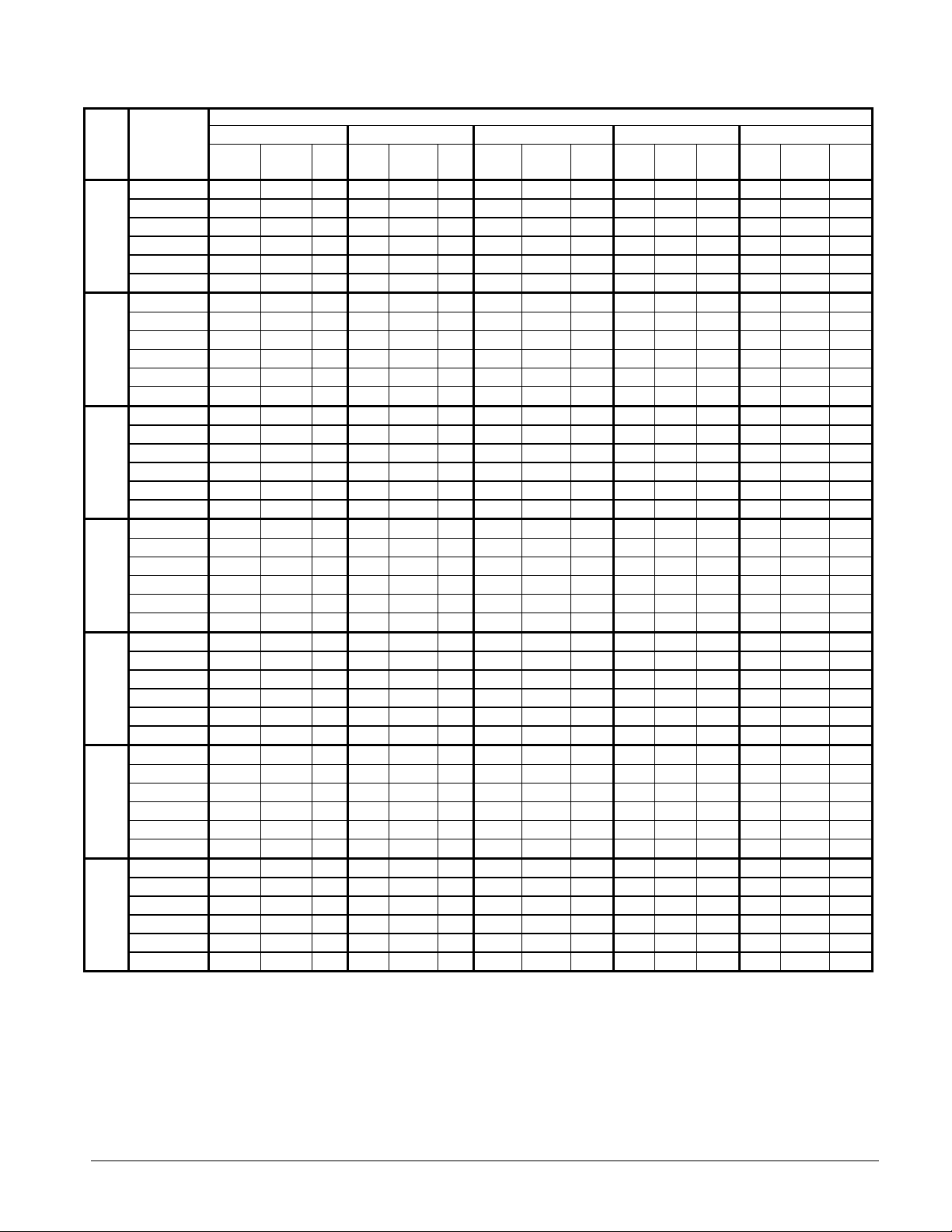
Table 5, ALR 110F - 150F, R-22, SI Units
AMBIENT AIR TEMPERATURE
ALR
SIZE
110F
120F
130F
135F
140F
145F
150F
NOTES:
1. Ratings based on HCFC-22, evaporator fouling of 0.0176, evaporator temperature drop of 5.6°C and sea level altitude.
2. For 208V units multiply capacity and COP by 0.98.
3. For units with SpeedTrol option multiply capacity and COP by 0.99.
4. Interpolation is allowed; extrapolation is not permitted. Consult McQuay for performance outside the cataloged ratings.
5. kWi input is for compressors only. COP is for the entire unit, including compressors, fan motors and control power.
6. For LWT of 5°C and below please refer to application considerations for reciprocating chillers.
LWT
(°C)
5.0 (41.0°F) 412.8 100.4 3.6 392.0 109.1 3.2 369.8 117.7 2.8 346.6 126.3 2.5 325.1 134.8 2.2
6.0 (42.8°F) 424.5 101.6 3.7 403.6 110.6 3.2 381.4 119.4 2.8 357.6 128.3 2.5 335.0 137.1 2.2
7.0 (44.6°F) 438.2 102.8 3.7 415.4 112.1 3.3 393.7 121.1 2.9 368.5 130.3 2.5 344.9 139.4 2.2
8.0 (46.4°F) 450.7 103.9 3.8 427.1 113.5 3.3 404.8 122.9 2.9 378.9 132.2 2.6 354.7 141.7 2.3
9.0 (48.2°F) 461.9 105.0 3.9 437.7 114.9 3.4 414.8 124.6 3.0 388.4 134.2 2.6 363.8 144.1 2.3
10.0 (50.0°F) 478.3 106.2 3.9 454.2 116.5 3.5 429.2 126.2 3.0 403.5 136.2 2.7 378.2 146.4 2.3
5.0 (41.0°F) 455.3 107.6 3.5 432.3 117.0 3.1 407.8 126.1 2.7 382.2 135.4 2.4 358.5 144.5 2.1
6.0 (42.8°F) 468.2 108.9 3.6 445.0 118.6 3.2 420.6 128.0 2.8 394.4 137.5 2.4 369.4 147.0 2.2
7.0 (44.6°F) 483.3 110.1 3.6 458.1 120.2 3.2 434.2 129.9 2.8 406.4 139.6 2.5 380.3 149.4 2.2
8.0 (46.4°F) 497.0 111.4 3.7 471.0 121.7 3.3 446.4 131.7 2.9 417.9 141.7 2.5 391.1 151.9 2.2
9.0 (48.2°F) 509.3 112.6 3.8 482.7 123.2 3.3 457.5 133.6 2.9 428.3 143.8 2.6 401.1 154.4 2.3
10.0 (50.0°F) 527.5 113.9 3.9 500.8 124.8 3.4 473.3 135.3 3.0 445.0 146.0 2.6 417.0 156.9 2.3
5.0 (41.0°F) 482.7 117.9 3.6 458.3 128.1 3.2 432.3 138.2 2.8 405.2 148.3 2.5 380.1 158.3 2.2
6.0 (42.8°F) 496.3 119.3 3.6 471.8 129.9 3.2 445.9 140.2 2.8 418.1 150.7 2.5 391.6 161.1 2.2
7.0 (44.6°F) 512.3 120.7 3.7 485.6 131.7 3.2 460.3 142.3 2.9 430.8 153.0 2.5 403.2 163.7 2.2
8.0 (46.4°F) 526.9 122.1 3.8 499.3 133.3 3.3 473.3 144.3 2.9 443.0 155.3 2.6 414.7 166.4 2.2
9.0 (48.2°F) 540.0 123.3 3.8 511.7 135.0 3.4 485.0 146.3 2.9 454.1 157.6 2.6 425.3 169.2 2.3
10.0 (50.0°F) 559.2 124.7 3.9 531.0 136.8 3.4 501.8 148.3 3.0 471.7 160.0 2.6 442.1 171.9 2.3
5.0 (41.0°F) 497.9 124.6 3.5 472.8 135.5 3.1 446.0 146.1 2.7 418.0 156.8 2.4 392.1 167.4 2.1
6.0 (42.8°F) 512.0 126.1 3.6 486.7 137.4 3.2 460.0 148.3 2.8 431.4 159.3 2.4 404.0 170.3 2.2
7.0 (44.6°F) 528.5 127.6 3.6 501.0 139.2 3.2 474.9 150.4 2.8 444.5 161.7 2.5 416.0 173.1 2.2
8.0 (46.4°F) 543.5 129.0 3.7 515.1 141.0 3.3 488.3 152.6 2.9 457.0 164.2 2.5 427.8 176.0 2.2
9.0 (48.2°F) 557.0 130.4 3.8 527.9 142.7 3.3 500.3 154.7 2.9 468.5 166.6 2.6 438.7 178.9 2.3
10.0 (50.0°F) 576.9 131.9 3.9 547.8 144.6 3.4 517.7 156.7 3.0 486.7 169.2 2.6 456.1 181.7 2.3
5.0 (41.0°F) 520.1 130.8 3.4 493.9 142.2 3.0 465.9 153.3 2.7 436.7 164.6 2.4 409.6 175.6 2.1
6.0 (42.8°F) 534.9 132.3 3.5 508.5 144.2 3.1 480.6 155.6 2.7 450.6 167.2 2.4 422.0 178.7 2.1
7.0 (44.6°F) 552.1 133.9 3.6 523.3 146.1 3.2 496.0 157.9 2.8 464.3 169.7 2.5 434.5 181.7 2.2
8.0 (46.4°F) 567.8 135.4 3.7 538.1 147.9 3.3 510.0 160.1 2.9 477.4 172.3 2.5 446.9 184.7 2.2
9.0 (48.2°F) 581.9 136.9 3.8 551.4 149.8 3.3 522.7 162.4 2.9 489.4 174.8 2.6 458.3 187.8 2.3
10.0 (50.0°F) 602.7 138.4 3.9 572.2 151.8 3.4 540.8 164.5 3.0 508.4 177.5 2.6 476.4 190.7 2.3
5.0 (41.0°F) 533.4 133.4 3.5 506.4 145.0 3.1 477.7 156.4 2.7 447.8 167.8 2.4 420.1 179.1 2.1
6.0 (42.8°F) 548.5 134.9 3.6 521.4 147.0 3.2 492.8 158.7 2.8 462.1 170.5 2.4 432.8 182.2 2.2
7.0 (44.6°F) 566.2 136.5 3.7 536.7 149.0 3.2 508.7 161.0 2.8 476.1 173.1 2.5 445.6 185.2 2.2
8.0 (46.4°F) 582.2 138.1 3.7 551.8 150.8 3.3 523.0 163.3 2.9 489.6 175.7 2.5 458.2 188.3 2.2
9.0 (48.2°F) 596.7 139.5 3.8 565.5 152.7 3.3 536.0 165.6 2.9 501.8 178.3 2.6 470.0 191.4 2.3
10.0 (50.0°F) 618.0 141.1 3.9 586.8 154.7 3.4 554.5 167.7 3.0 521.3 181.0 2.6 488.6 194.5 2.3
5.0 (41.0°F) 556.7 139.6 3.5 528.6 151.7 3.1 498.6 163.6 2.7 467.3 175.6 2.4 438.4 187.4 2.1
6.0 (42.8°F) 572.5 141.2 3.6 544.2 153.8 3.2 514.3 166.0 2.8 482.3 178.4 2.4 451.7 190.7 2.2
7.0 (44.6°F) 590.9 142.9 3.7 560.1 155.9 3.2 530.9 168.5 2.8 496.9 181.1 2.5 465.1 193.9 2.2
8.0 (46.4°F) 607.7 144.5 3.7 575.9 157.9 3.3 545.9 170.9 2.9 511.0 183.9 2.5 478.3 197.1 2.2
9.0 (48.2°F) 622.8 146.0 3.8 590.2 159.8 3.3 559.4 173.3 2.9 523.7 186.6 2.6 490.5 200.4 2.3
10.0 (50.0°F) 645.0 147.7 3.9 612.4 162.0 3.4 578.8 175.5 3.0 544.1 189.5 2.6 509.9 203.5 2.3
25°C (77°F) 30°C (86°F) 35°C (95°F) 40°C (104°F) 45°C (113°F)
Capac.kWPWR
kWi
COP
Capac.kWPWR
kWi
COP
Capac.kWPWR
kWi
COP
Capac.kWPWR
kWi
COP
Capac.kWPWR
kWi
COP
Product Manual ALR2-3 ALR 110F – 150F 13
Page 14
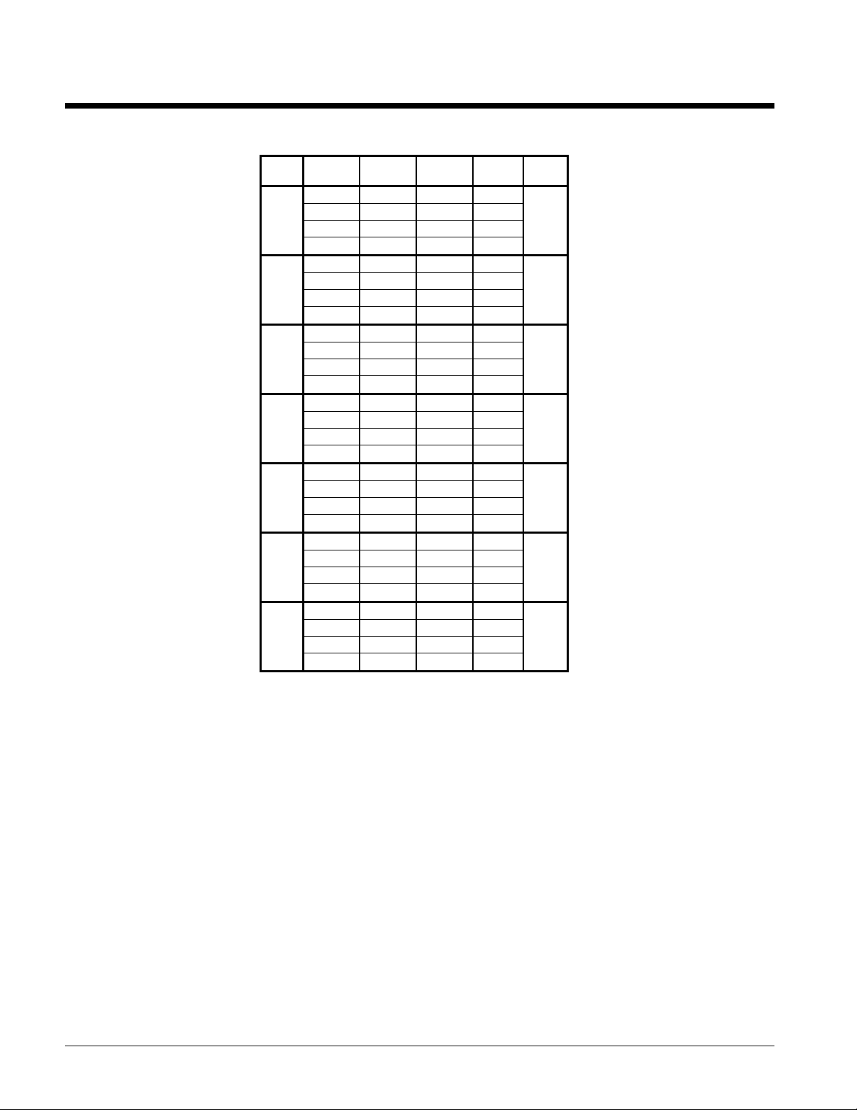
Part Load Data
Table 6, Part Load Data R-22,
Unit
% Load
Size
100.00 110.9 135.6 9.8
110F 75.00 83.5 79.9 12.5 14.0
50.00 55.6 44.9 14.9
25.00 27.9 21.1 15.9
100.00 122.2 152.8 9.6
120F 75.00 92.4 89.9 12.3 14.0
50.00 61.6 48.7 15.2
25.00 30.8 24.1 15.3
100.00 129.6 161.0 9.7
130F 75.00 97.2 95.9 12.2 13.6
50.00 64.8 54.0 14.4
25.00 32.4 24.8 15.7
100.00 133.7 168.0 9.6
135F 75.00 100.3 100.3 12.0 13.4
50.00 66.8 55.3 14.5
25.00 33.4 28.2 14.2
100.00 139.7 174.8 9.6
140F 75.00 104.7 102.5 12.3 13.7
50.00 69.8 56.9 14.7
25.00 34.9 27.0 15.5
100.00 143.2 178.2 9.6
145F 75.00 107.5 104.4 12.4 13.5
50.00 71.6 61.3 14.0
25.00 35.9 27.7 15.5
100.00 149.5 186.0 9.6
150F 75.00 112.1 109.4 12.3 13.4
50.00 74.7 64.4 13.9
25.00 37.4 29.4 15.3
Capacity
Tons
Unit Power
kW
EER IPLV
14 ALR 110F – 150F Product Manual ALR2-3
Page 15
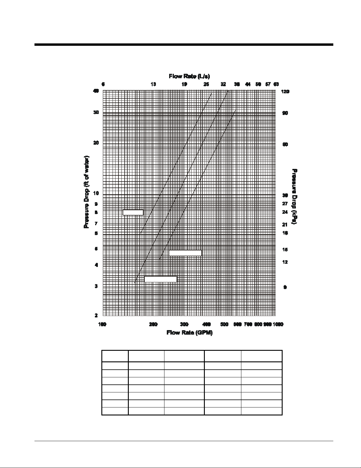
Pressure Drops
Figure 5, 110F through 150F Evaporator Pressure Drop Curve
ALR 110
ALR 145 - 150
ALR 120 - 140
Minimum/Maximum Flow Rates
ALR Unit
Size
110
120
130
135
140
145
150
Minimum Flow
gpm (l/s)
165 (10.4) 6.0 (17.9) 435 (27.4) 39.0 (116.0)
180 (11.4) 4.3 (12.8) 480 (30.3) 30.5 (90.0)
195 (12.3) 5.1 (15.2) 520 (32.8) 37.5 (111.8)
200 (12.6) 5.3 (15.8) 535 (33.8) 40.0 (119.2)
205 (13.0) 5.8 (17.3) 550 (34.7) 42.0 (125.2)
215 (13.6) 4.3 (12.8) 570 (36.0) 29.5 (87.9)
220 (13.9) 4.5 (13.4) 590 (37.2) 31.0 (92.4)
Pressure Drop
ft. (kPa)
Maximum Flow
gpm (l/s)
Pressure Drop
ft. (kPa)
Product Manual ALR2-3 ALR 110F – 150F 15
Page 16
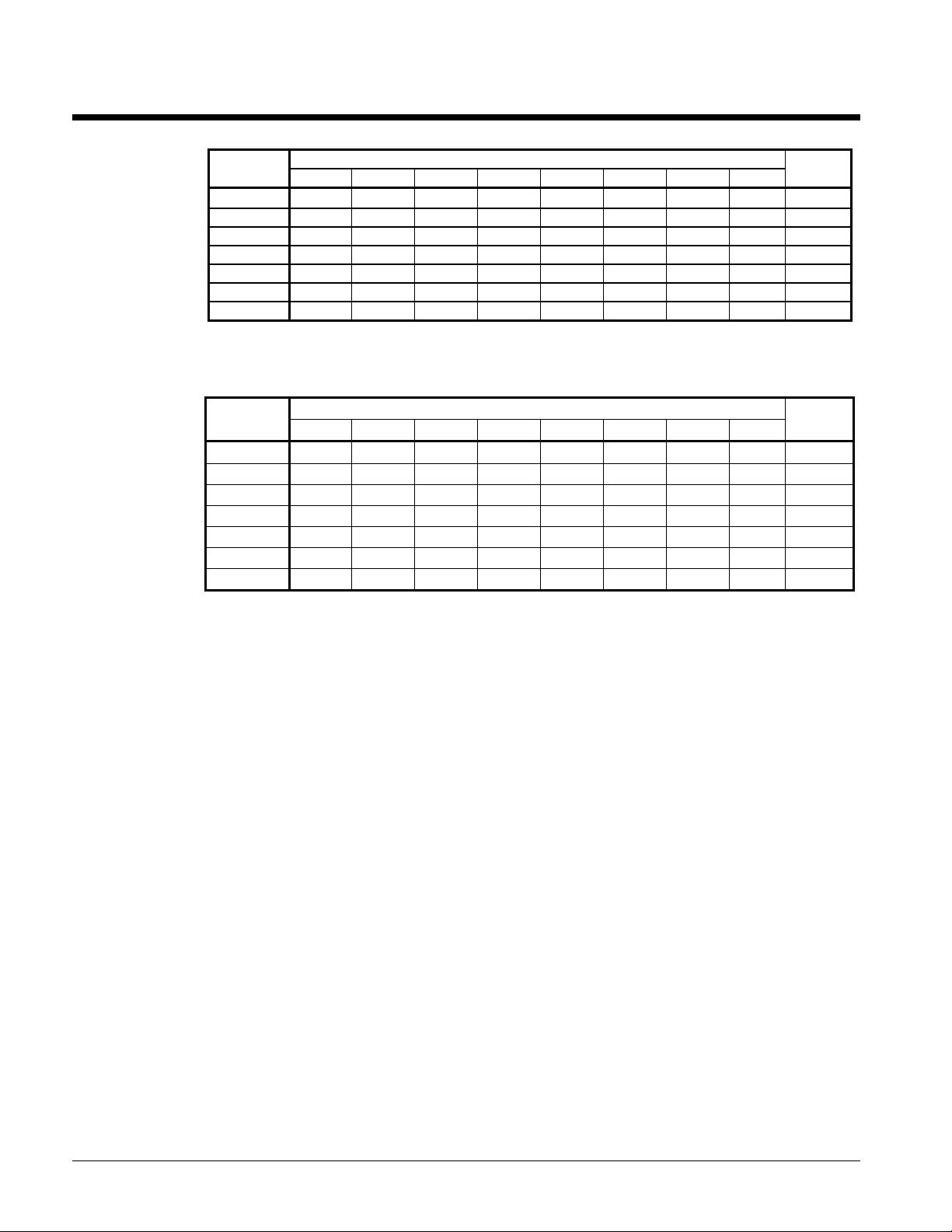
Sound Data
Table 7, ALR 110F - 150F, Sound Pressure
ALR
Unit Size
110 65 68 69 66 62 60 57 53 68.5
120
130
135
140
145
150
NOTES
1. Based on Uniform Spherical Radiation, Q=1
2. Sound pressure at 30 feet from unit.
63 hz 125 hz 250 hz 500 hz 1000 hz 2000 hz 4000 hz 8000 hz
65 68 69 66 62 60 57 53 68.5
66 69 70 67 63 61 58 54 69.5
66 69 70 67 63 61 58 54 69.5
67 70 71 68 63 61 59 54 70.0
67 70 71 68 63 61 59 54 70.0
68 71 72 69 64 62 59 55 71.0
Octave Band Sound Pressure Levels Per ARI Standard 370 (dB)
Table 8, ALR 110F - 150F, Sound Power
ALR
Unit Size
110 95 98 99 96 92 90 87 83 98.5
120
130
135
140
145
150
Per ARI 370 - Sound Rating of Large Outdoor Refrigerating and Air-Conditioning Equipment
63 hz 125 hz 250 hz 500 hz 1000 hz 2000 hz 4000 hz 8000 hz
95 98 99 96 92 90 87 83 98.5
96 99 100 97 93 91 89 84 99.5
96 99 100 97 93 91 89 84 99.5
97 100 101 98 93 91 89 84 100.0
97 100 101 98 93 91 89 84 100.0
98 101 102 99 94 92 89 85 101.0
Octave Band Sound Power Levels Per ARI Standard 370 (dB)
Overall "A"
Weighted
Overall "A"
Weighted
Sound levels can be as important as unit cost and efficiency, and must be addressed before the start
of any development program. Efforts by McQuay Design Engineers to design chillers that are
sensitive to the sound requirements of the market have paid off.
Background Information
Sound is a vibration in an elastic medium and is essentially a pressure and particle displacement
phenomena. A vibrating body produces compression waves and as the waves are emitted from the
vibrating body, molecules are ultimately compressed. These waves are transmitted through gases,
liquids, or solids-anything that is elastic or viscous.
The sound data provided in this section is presented with both sound pressure (Q=1 and 30 feet from
unit) and sound power levels. Sound power is the total sound energy radiated by a source per unit of
time integrated over the surface through which the sound is radiated. Sound power is a calculated
quantity and cannot be measured directly like sound pressure. Sound power is not dependent on the
surrounding environment or distance from the source, as is sound pressure.
Sound pressure varies with the distance from the source and is dependent on its surroundings. For
example, a brick wall located 10 feet from a unit will affect the sound pressure measurements differently
than a brick wall at 20 feet. Sound pressure is measured in decibels (dB), which is a dimensionless
ratio (on a logarithmic scale) between measured sound pressure and a reference sound pressure level.
Sound Pressure Levels - Full Load
Sound pressure tables give the overall "A" weighted sound pressure levels which are considered
typical of what may be measured in a free field with a hand held sound meter, in the absence of any
nearby reflective surfaces. The sound pressure levels (Table 7) are measured at 30 feet from the side
of the unit at 100% unit load, no reflecting walls Q=1, and ARI conditions, 95°F (35°C) ambient air
temperature and 54/44°F (12/7°C) evaporator water temperatures for air-cooled units.
16 ALR 110F – 150F Product Manual ALR2-3
Page 17

Sound Power Levels
Acoustical consultants may require sound power octave band data to perform a detailed acoustical
analysis. The previous tables present sound power levels per ARI Standard 370 “Sound Rating of
Large Outdoor Refrigerating and Air Conditioning Equipment”. These standards were developed to
establish uniform methods of determining the sound power radiated by large outdoor and indoor
equipment. The aforementioned methods are based on providing sound power levels by octave band
and the overall ‘A’ weighted value. Sound pressure measurements are taken over a prescribed area
around the unit and the data is mathematically calculated to give the sound power, dB.
Sound Reduction due to Distance from the Unit
The distance between a source of sound and the location of the sound measurement plays an
important role in minimizing sound problems. The equation below can be used to calculate the sound
pressure level at any distance if the sound power is known.
Lp=Lw-(20 log r) + (10 log Q) - .5
Lp = sound pressure
Lw = sound power
r = distance from unit in feet
Q = directionality factor
The directionality factor, "Q", is a dimensionless number that compensates for the type of sound
reflection from the source. For example, a unit sitting on a flat roof or ground with no other reflective
surfaces or attenuation due to grass, snow, etc., between source and receiver: Q=1.
Figure 6, "Q" Definition, Plan View, Unit Located in Center
Uniform Spherical Radiation
Q=1 no reflecting surface
Uniform Hemispherical Radiation
Q=2 single reflecting surface
Uniform Radiation over ¼ of sphere
Q=4 two reflecting surfaces
With Q=1, no reflecting walls, the equation simplifies to: Lp = Lw - (20)(log r) –0.5
With Q=2, for a unit sitting on a flat roof or ground with one wall as a reflective surface the equation
simplifies to: Lp = Lw - (20)(log r) + 2.5
The equations are reduced to table form in Table 9 for various distances and the three most usual
cases of "Q" type of location.
Table 9, dB Conversion of Sound Power to Pressure for Distance
Distance From Sound Source
ft (m)
30 (9) 30.0 27.1 24.0
50 (15) 34.5 31.6 28.5
75 (23) 38.0 35.1 32.0
100 (30) 40.5 37.6 34.5
150 (46) 44.0 41.1 38.0
200 (61) 46.5 43.6 40.5
300 (91) 50.0 47.6 44.0
dB Reduction from Sound Power at the Source
to Sound Pressure at Referenced Distance
Q=1 Q=2 Q=4
Product Manual ALR2-3 ALR 110F – 150F 17
Page 18

Figure 7, Sound Pressure Attenuation Due to Distance from Unit
(Plus or Minus from Table 7)
Air-Cooled Unit Orientation to Minimize Sound
The ALR chiller’s sound is directional in nature allowing the contractor/engineer to position the unit
to minimize potential noise problems. Because the sound pressure levels are lower at both ends of the
unit than at the sides, the chiller should be oriented such that the control box end or end opposite the
control box faces the direction where the lowest sound level is required.
The control box end provides an excellent acoustic barrier to the compressor sound as it covers one
full end of the unit. The sound pressure levels at the control box end will be 5 dBA less than on the
sides. On the end opposite the control box, the compressor sound is blocked by the coil structure,
evaporator and naturally attenuated by distance as the compressors are located approximately ¾ the
length of the unit away from this end. The sound pressure levels at the end opposite the control box
will be 4 dBA less than on the sides.
Figure 8, Sound Directionality
Sound pressure levels per Table 7
C
Compressor
Sound pressure levels
here 5 dBA lower
than Table 7
o
n
t
r
o
l
Evaporator
Compressor
Sound pressure levels per Table 7
Sound pressure levels
here 4 dBA lower
than Table 7
Sound Pressure Levels, Low Ambient Operation
Air-cooled unit operation below 95°F (35°C) will also result in lower sound pressure levels. The sound
pressure level will decrease 3 dB proportionally from 95°F to 65°F. For example, at 95°F the sound
pressure is per Error! Reference source not found., at 85°F one dB can be subtracted, at 75°F two dB
can be subtracted, and so on for any temperature between 65°F and 95°F.
18 ALR 110F – 150F Product Manual ALR2-3
Page 19

Sound Pressure Levels, Multiple Units
Multiple air-cooled unit installations will have a higher sound level than a single unit on a
doubling basis. Two units will have approximately 3 dB higher sound level of one unit, 4 units
will be approximately 6 dB louder, and 8 units approximately 9 dB louder than one unit.
Sound Control
Walls adjacent to a unit
(20 feet {6.1 meters} or
less) will reflect sound
outwards, increasing the
sound pressure on the
side away from the wall.
This sound increase could
be as high as 3 dB for one
wall and as high as 6 dB
for a corner location. Unit
orientation and/or
distance as noted above
will decrease sound levels.
Sound levels can also be controlled by the installation of barrier walls. To be effective as sound
blockers, walls must be solid with no open penetrations. Sound tends to leak out of openings.
Block walls with filler material and slots on the side facing the unit are especially effective. The
wall should be about 10 feet high (two feet higher than the unit) and located at least 10 feet away
so as not to affect unit performance. A three-sided enclosure will be the most effective solution
and will reduce sound levels by about 10 dB. Remember that the wall will increase the sound
level on the side opposite it by 3 to 6 dB (one or three sided wall). Note: The effect of adjacent
walls on air recirculation and restriction must always be considered when employing sound
barrier walls.
Product Manual ALR2-3 ALR 110F – 150F 19
Page 20

Electrical Data
Table 10, ALR 110F - 150F, Electrical Data, Single Point
ALR
Unit
Size
110F
120F
130F
135F
140F
145F
150F
NOTES
1. A "HACR" breaker is a circuit breaker designed for use on equipment with multiple motors. It stands for Heating, Air Conditioning, Refrigeration.
2. See page 25 for other Electrical Data notes.
Volts Hz
208
230
460
575
208
230
460
575
208
230
460
575
208
230
460
575
208
230
460
575
208
230
460
575
208
230
460
575
60
60
60
60
60
60
60
Min. Circuit
Ampacity
(MCA)
503
492
248
188
555
526
274
200
592
554
293
210
626
590
302
224
656
622
310
236
656
622
310
236
690
666
334
261
Field Wire
Quantity Wire Gauge Quantity Size
6
6
3
3
6
6
3
3
6
6
3
3
6
6
3
3
6
6
3
3
6
6
3
3
6
6
3
3
400
350
250
3/0
500
400
300
4/0
500
500
350
4/0
400
350
350
4/0
400
400
400
250
400
400
400
250
500
500
400
300
(Conduit Connection)
Hub
1 4.00 (102) 600
1 4.00 (102) 600
1 2.50 (64) 300
1 2.00 (51) 200
1 4.00 (102) 600
1 4.00 (102) 600
1 2.50 (64) 300
1 2.00 (51) 225
1 4.00 (102) 700
1 4.00 (102) 600
1 2.50 (64) 300
1 2.00 (51) 225
2 2.50 (64) 700
2 2.50 (64) 700
1 2.50 (64) 350
1 2.00 (51) 250
2 3.00 (76) 700
2 3.00 (76) 700
1 2.50 (64) 350
1 2.50 (64) 250
2 3.00 (76) 700
2 3.00 (76) 700
1 2.50 (64) 350
1 2.50 (64) 250
2 3.00 (76) 800
2 3.00 (76) 800
1 3.00 (76) 350
1 2.50 (64) 300
Fuse or HACR Breaker Size
Recommended Maximum
600
600
300
225
600
500
300
225
700
600
350
250
700
700
350
250
700
700
350
250
700
700
350
250
800
800
400
300
20 ALR 110F – 150F Product Manual ALR2-3
Page 21

Table 11, ALR 110F - 150F, Electrical Data, Multiple Point
ALR
Unit
Size
110F
120F
130F
135F
140F
145F
150F
Notes:
1. Separate disconnects are required for each circuit.
2. See page 25 for other Electrical Data notes.
Min.
Ckt.
Volts
Amps
MCA
208 60 3 6 1 1.50 (38) 60 60
230 60 3 6 1 1.50 (38) 60 60
460 29 3 10 1 1.00 (25) 30 30
575 24 3 10 1 1.00 (25) 25 25
208 60 3 6 1 1.50 (38) 60 60
230 60 3 6 1 1.50 (38) 60 60
460 29 3 10 1 1.00 (25) 30 30
575 24 3 10 1 1.00 (25) 25 25
208 71 3 4 1 2.00 (51) 80 80
230 71 3 4 1 2.00 (51) 80 80
460 35 3 8 1 1.25 (32) 35 35
575 28 3 10 1 1.00 (25) 30 30
208 71 3 4 1 2.00 (51) 80 80
230 71 3 4 1 2.00 (51) 80 80
460 35 3 8 1 1.25 (32) 35 35
575 28 3 10 1 1.00 (25) 30 30
208 71 3 4 1 2.00 (51) 80 80
230 71 3 4 1 2.00 (51) 80 80
460 35 3 8 1 1.25 (32) 35 35
575 28 3 10 1 1.00 (25) 30 30
208 71 3 4 1 2.00 (51) 80 80
230 71 3 4 1 2.00 (51) 80 80
460 35 3 8 1 1.25 (32) 35 35
575 28 3 10 1 1.00 (25) 30 30
208 71 3 4 1 2.00 (51) 80 80
230 71 3 4 1 2.00 (51) 80 80
460 35 3 8 1 1.25 (32) 35 35
575 28 3 10 1 1.00 (25) 30 30
Power Supply
Fans and Controls
Field Wire Hub Field Wire Hub Field Wire Hub
Qty.
Wire
Size
Qty.
Hub
Size
Field
Fusing(1)
Rec.
Fuse
Size
Max.
Fuse
Size
Min.
Ckt
Amps
MCA
218
218
108
83
251
240
124
91
277
257
137
97
296
277
142
104
311
293
146
110
311
293
146
110
311
293
146
110
Power Supply
Wire
Qty.
Size
3
3
3
3
3
250
3
250
3
3
3
300
3
300
3
3
3
350
3
300
3
3
3
400
3
350
3
3
3
400
3
350
3
3
3
400
3
350
3
3
Circuit #1
Qty
4/0
4/0
2
4
1
3
1/0
3
1/0
2
1/0
2
1/0
2
1/0
2
Field
Fusing (1)
Rec.
Fuse
Hub
Size
Size
2.00
1
1
1
1
1
1
1
1
1
1
1
1
1
1
1
1
1
1
1
1
1
1
1
1
1
1
1
1
(51)
2.00
(51)
1.25
(32)
1.00
(25)
2.50
(64)
2.50
(64)
1.25
(32)
1.25
(32)
2.50
(64)
2.50
(64)
1.50
(38)
1.25
(32)
2.50
(64)
2.50
(64)
1.50
(38)
1.25
(32)
2.50
(64)
2.50
(64)
1.50
(38)
1.25
(32)
2.50
(64)
2.50
(64)
1.50
(38)
1.25
(32)
2.50
(64)
2.50
(64)
1.50
(38)
1.25
(32)
250 300 251
250 300 240
125 150 124
100 110 91
300 300 277
300 300 257
150 150 137
110 125 97
350 400 277
300 350 257
175 175 137
110 125 97
350 400 296
350 350 277
175 200 142
125 125 104
350 400 311
350 400 293
175 200 146
125 150 110
350 400 311
350 400 293
175 200 146
125 150 110
350 400 344
350 400 336
175 200 170
125 150 135
Max.
Fuse
Size
Min.
Ckt
Amps
MCA)
Power Supply
Circuit #2
Wire
Qty.
Size
3
250
3
250
3
1
3
3
3
300
3
300
3
1/0
3
3
3
300
3
300
3
1/0
3
3
3
350
3
300
3
1/0
3
2
3
400
3
350
3
1/0
3
2
3
400
3
350
3
1/0
3
2
3
500
3
500
3
2/0
3
1/0
Qty.
1
1
1
1
1
1
1
1
1
1
1
1
1
1
1
1
1
1
1
1
1
1
1
1
1
1
1
1
Hub
Size
2.50
(64)
2.50
(64)
1.25
(32)
1.25
(32)
2.50
(64)
2.50
(64)
1.50
(38)
1.25
(32)
2.50
(64)
2.50
(64)
1.50
(38)
1.25
(32)
2.50
(64)
2.50
(64)
1.50
(38)
1.25
(32)
3.00
(76)
2.50
(64)
1.50
(38)
1.25
(32)
3.00
(76)
2.50
(64)
1.50
(38)
1.25
(32)
3.00
(76)
3.00
(76)
2.00
(51)
1.50
(38)
Field
Fusing (1)
Rec.
Max.
Fuse
Fuse
Size
Size
300 350
225 350
150 175
110 125
300 400
250 350
175 175
110 125
300 400
250 350
175 175
110 125
350 400
300 400
175 200
125 150
350 400
300 400
175 200
125 150
350 400
300 400
175 200
125 150
400 500
350 500
200 250
175 200
Product Manual ALR2-3 ALR 110F – 150F 21
Page 22

Table 12, ALR 110F -150F, Compressor and Condenser Fan Motor Amp Draw
ALR
Unit
Volts
Size
208
110F
120F
130F
135F
140F
145F
150F
See page 25 for other Electrical Data notes.
230
460
575
208
230
460
575
208
230
460
575
208
230
460
575
208
230
460
575
208
230
460
575
208
230
460
575
Rated Load Amps Locked Rotor Amps
Compressors Compressors
No.1No.2No.3No.
97 97 97 123
97 97 97 114
48 48 48 61
37 37 37 43
97 123 123 123
97 114 114 114
48 61 61 61
37 43 43 43
123 123 123 123
114 114 114 114
61 61 61 61
43 43 43 43
123 123 138 138
114 114 130 130
61 61 65 65
43 43 49 49
138 138 138 138
130 130 130 130
65 65 65 65
49 49 49 49
138 138 138 138
130 130 130 130
65 65 65 65
49 49 49 49
138 138 138 165
130 130 130 165
65 65 65 84
49 49 49 69
Motors
4
(Each)
No.
Fan
Of
Fan
Fan
Motors
Motor
(Each)
5.8 10 23.7 565 565 565 650 340 340 340 400
5.8 10 21.4 565 565 565 594 340 340 340 340
2.8 10 10.7 283 283 283 297 156 156 156 195
2.3 10 11.5 230 230 230 245 138 138 138 152
5.8 10 23.7 565 650 650 650 340 400 400 400
5.8 10 21.4 565 594 594 594 340 340 340 340
2.8 10 10.7 283 297 297 297 156 195 195 195
2.3 10 11.5 230 245 245 245 138 152 152 152
5.8 12 23.7 650 650 650 650 400 400 400 400
5.8 12 21.4 594 594 594 594 340 340 340 340
2.8 12 10.7 297 297 297 297 195 195 195 195
2.3 12 11.5 245 245 245 245 152 152 152 152
5.8 12 23.7 650 650 754 754 400 400 463 463
5.8 12 21.4 594 594 594 594 340 340 340 340
2.8 12 10.7 297 297 297 297 195 195 195 195
2.3 12 11.5 245 245 245 245 152 152 152 152
5.8 12 23.7 754 754 754 754 463 463 463 463
5.8 12 21.4 594 594 594 594 340 340 340 340
2.8 12 10.7 297 297 297 297 195 195 195 195
2.3 12 11.5 245 245 245 245 152 152 152 152
5.8 12 23.7 754 754 754 754 463 463 463 463
5.8 12 21.4 594 594 594 594 340 340 340 340
2.8 12 10.7 297 297 297 297 195 195 195 195
2.3 12 11.5 245 245 245 245 152 152 152 152
5.8 12 23.7 754 754 754 1070 463 463 463 654
5.8 12 21.4 594 594 594 1070 340 340 340 654
2.8 12 10.7 297 297 297 510 195 195 195 330
2.3 12 11.5 245 245 245 405 152 152 152 262
Across-The-Line Reduced Inrush
No. 1 No. 2 No. 3 No. 4 No. 1 No. 2 No. 3 No. 4
22 ALR 110F – 150F Product Manual ALR2-3
Page 23

Table 13, ALR 110F - 150F, Field Wiring Data, Single Point Power
ALR
Unit
Size
110F
120F
130F
135F
140F
145F
150F
See page 25 for other Electrical Data notes.
Volts
208 840 (2 qty.) 1/0 - 600 MCM 600 (2 qty.) 250 - 500 MCM
230 840 (2 qty.) 1/0 - 600 MCM 600 (2 qty.) 250 - 500 MCM
460 335 (1 qty.) #4 - 400 MCM 400 (1 qty.) 250 - 500 MCM
575 335 (1 qty.) #4 - 400 MCM 250 (1qty.) #4 - 350 MCM
208 840 (2 qty.) 1/0 - 600 MCM 600 (2 qty.) 250 - 500 MCM
230 840 (2 qty.) 1/0 - 600 MCM 600 (2 qty.) 250 - 500 MCM
460 335 (1 qty.) #4 - 400 MCM 400 (1 qty.) 250 - 500 MCM
575 335 (1 qty.) #4 - 400 MCM 250 (1qty.) #4 - 350 MCM
208 840 (2 qty.) 1/0 - 600 MCM N/A
230 840 (2 qty.) 1/0 - 600 MCM N/A
460 335 (1 qty.) #4 - 400 MCM 400 (1 qty.) 250 - 500 MCM
575 335 (1 qty.) #4 - 400 MCM 250 (1qty.) #4 - 350 MCM
208 840 (2 qty.) 1/0 - 600 MCM N/A
230 840 (2 qty.) 1/0 - 600 MCM N/A
460 335 (1 qty.) #4 - 400 MCM 400 (1 qty.) 250 - 500 MCM
575 335 (1 qty.) #4 - 400 MCM 250 (1qty.) #4 - 350 MCM
208 840 (2 qty.) 1/0 - 600 MCM N/A
230 840 (2 qty.) 1/0 - 600 MCM N/A
460 335 (1 qty.) #4 - 400 MCM 400 (1 qty.) 250 - 500 MCM
575 335 (1 qty.) #4 - 400 MCM 400 (1 qty.) 250 - 500 MCM
208 840 (2 qty.) 1/0 - 600 MCM N/A
230 840 (2 qty.) 1/0 - 600 MCM N/A
460 335 (1 qty.) #4 - 400 MCM 400 (1 qty.) 250 - 500 MCM
575 335 (1 qty.) #4 - 400 MCM 400 (1 qty.) 250 - 500 MCM
208 840 (4 qty.) 1/0 - 600 MCM N/A
230 840 (4 qty.) 1/0 - 600 MCM N/A
460 840 (2 qty.) 1/0 - 600 MCM 400 (1 qty.) 250 - 500 MCM
575 840 (2 qty.) 1/0 - 600 MCM 400 (1 qty.) 250 - 500 MCM
Terminal
Amps
Wiring to
Standard Power Block
Connector Wire Range/Phase
(Copper Wire Only)
Terminal
Amps
Wiring to Optional Factory Mounted
Disconnect Switch
Connector Wire Range/Phase
(Copper Wire Only)
Product Manual ALR2-3 ALR 110F – 150F 23
Page 24

Table 14, ALR 110F through 150F, Field Wiring Data, Multiple Point Power
ALR
Unit
Size
110F
120F
130F
135F
140F
145F
150F
See page 25 for all Electrical Data notes.
Volts
208 175 335 335 (1 qty.) #12 - 2/0 (1 qty.) #4 - 400 MCM (1 qty.) #4 - 400 MCM
230 175 335 335 (1 qty.) #12 - 2/0 (1 qty.) #4 - 400 MCM (1 qty.) #4 - 400 MCM
460 175 175 175 (1 qty.) #12 - 2/0 (1 qty.) #12 - 2/0 (1 qty.) #12 - 2/0
575 175 175 175 (1 qty.) #12 - 2/0 (1 qty.) #12 - 2/0 (1 qty.) #12 - 2/0
208 175 840 840 (1 qty.) #12 - 2/0 (2 qty.) 1/0 - 600 MCM (2 qty.) 1/0 - 600 MCM
230 175 840 840 (1 qty.) #12 - 2/0 (2 qty.) 1/0 - 600 MCM (2 qty.) 1/0 - 600 MCM
460 175 335 335 (1 qty.) #12 - 2/0 (1 qty.) #4 - 400 MCM (1 qty.) #4 - 400 MCM
575 175 335 335 (1 qty.) #12 - 2/0 (1 qty.) #4 - 400 MCM (1 qty.) #4 - 400 MCM
Terminal Amps Connector Wire Range Per Phase (Copper Wire Only)
Circuit 1 Circuit 2 Circuit 3 Circuit 1 (Fans) Circuit 2 Circuit 3
Wiring to Standard Power Block
24 ALR 110F – 150F Product Manual ALR2-3
Page 25

Notes for “Electrical Data Single Point” and “Electrical Data Multiple Point” Power:
1. Table 10 through Table 11, Field Fuse Size for recommended and maximum is based on use of time-delay
fuses.
2. Unit wire size ampacity (MCA) is equal to 125% of the largest compressor-motor RLA plus 100% of RLA
of all other loads in the circuit including the control transformer.
3. The control transformer is furnished as standard.
4. If a separate 115V power supply is used for the control circuit, then size wire for 12 amps.
5. Recommended power lead wire sizes for 3 conductors per conduit are based on 100% conductor ampacity
in accordance with NEC. Wire sizes for 6 conductors per conduit are based on 80% conductor ampacity in
accordance with NEC. Voltage drop has not been included. Therefore, it is recommended that power leads
be kept short. All terminal block connections must be made with copper (type THW) wire.
6. The unit power terminal block may have 2 lugs per phase. Single or parallel conductors should be used for
power connections as listed under “Recommended Power Lead Wire Size.”
7. “Recommended Fuse Sizes” are selected at approximately 150% of the largest compressor RLA, plus 100%
of all other loads in the circuit.
8. “Maximum Fuse Sizes” are selected at approximately 225% of the largest compressor RLA, plus 100% of
all other loads in the circuit.
9. The recommended power lead wire sizes are based on an ambient temperature of 86°F. Ampacity
correction factors must be applied for other ambient temperatures. Refer to the National Electrical Code
Handbook.
10. The MCA may vary depending on options selected (SpeedTrol, totally enclosed fan motors).
Voltage Limitations:
Within 10% of nameplate rating.
Notes for “Compressor and Condenser Fan Amp Draw”:
1. Compressor RLA values are for wiring sizing purposes only but do not reflect normal operating current
draw at rated capacity. If unit is equipped with SpeedTrol condenser fan motors, the first motor on each
refrigerant circuit is a single phase, 1hp motor, with a FLA of 2.8 amps at 460 volts, 5.6 amps at 208, 230,
and 575 volts.
2. Compressor LRA for reduced inrush start is for the first winding only. If the unit is equipped with
SpeedTrol motors, the first motor is a single phase, 1 hp motor, with a LRA of 7.3 amps at 460 volts, 14.5
amps at 208, 230 and 575 volts.
Notes for “Field Wiring Data” - Both Single and Multiple Point Power:
1. Optional disconnect switch is only available on single power source units.
2. Single point power supply requires a single disconnect to supply electrical power to the unit. This power
must be fused.
3. Multiple point power supply requires three independent power circuits, each with separate disconnect.
4. All field wiring to unit power block or optional non-fused disconnect switch must be copper.
5. All field wire size values given in table apply to 75°C rated wire per NEC.
Product Manual ALR2-3 ALR 110F – 150F 25
Page 26

Figure 9, ALR 110F through 150F, Typical Field Wiring Diagram
2
8
AMBIENT
24VACOF
F
CHILLERFLOW
LEGENDFIELDCONNECTIONTERMINAL
CHILLERCONTROL(CIRCUIT1
)
(CIRCUIT2
)
3 PHASE
1
2
4
P OW ER
SUP PLY
OPTIONAL
DISCONNECT
B K
540
F 1
S 1
1 7
1 8
13 F2
UNI T MAIN
TERM I NALBLOCK
SEPARTE 115V
POW ERFORCOOLER
HEATER (SEE NOTEA)
C OOLER HEATER
THEMOSTAT TC2.
1 20 V
24 V
T2
STANDARD FUSED
CONTROL CIRCUIT
TRANSFORMER
COOLER HEATER
C HILLE R C O NTROL
TOC OMP RESSOR(S)
AND FAN MOTORS.
WH
1 6
54 5
NB
2 7
WH
SEE NOTE A
SWI TCHCONTACT
AUT O
5
ON
TI MECLOCK
CO NTACT
TH ERMOSTAT
B I4
B I1
CHI LLERCONTROL
N OTE A :
IT MA Y B E DE S IRAB L E TO HA V E T HE UN IT
C O OLER HE AT ER ON A S EPA RA TE DISC ON NE CT
S WITC H FROM T HE M A IN UN IT P OWE R S UP P LY
S O TH AT T HE U NIT M A Y B E S HUT DOWN WITH
O UT DE FE AT ING TH E FRE EZ E P ROTE C TIO N
FAC T ORY WIRING
F I ELD WIRING
P ROV IDED B Y THE CO OLE R H EA TE R. T O A C C O MP L ISH T HIS, REM OV E WIRE S 5 40 A N D 5 4 5
A N D F IELD WIRE TE RM INA LS 13 A ND 16 T O A
S E PA RAT E 11 5V P OWE R SO URC E.
26 ALR 110F – 150F Product Manual ALR2-3
Page 27

Physical Data
Table 15, Physical Data ALR 110F through 135F
PHYSICAL DATA
BASIC DATA Ckt.1 Ckt.2 Ckt.1 Ckt.2 Ckt.1 Ckt.2 Ckt.1 Ckt.2
Unit Capacity @ ARI Conditions, Tons (kW) (1) 110.9 (388.1) 122.2 (427.7) 129.6 (453.6) 133.7 (468.0)
Number Of Refrigerant Circuits 2 2 2 2
Unit Operating Charge, R-22, Lbs. 115 115 120 120 120 120 120 120
Unit Operating Charge, R-22, (kg) (52.1) (52.1) (54.4) (54.4) (54.4) (54.4) (54.4) (54.4)
Cabinet Dimensions, LxWxH, In. 229 x 83 x 89 229 x 83 x 89 229 x 83 x 89 229 x 83 x 89
Cabinet Dimensions, LxWxH, (mm) (5809 x 2118 x 2210) (5809 x 2118 x 2210) (5809 x 2118 x 2210) (5817 x 2118 x 2210)
Unit Operating Weight, Lbs. (kg) 9700 (4394) 9880 (4476) 9880 (4476) 9880 (4476)
Unit Shipping Weight, Lbs. (kg) 9420 (4267) 9550 (4326) 9550 (4326) 9550 (4326)
Add'l Weight If Copper Finned Coils, Lbs. (kg) 1370 (620) 1370 (620) 1370 (620) 1370 (620)
COMPRESSORS
Type Semi-Hermetic Semi-Hermetic Semi-Hermetic Semi-Hermetic
Nominal Horsepower 30-30 30-35 30-35 35-35 35-35 35-35 35-40 35-40
Number Of Cylinders Per Compressor 6 - 6 6 - 6 6 - 6 6 - 6 6 - 6 6 - 6 6 - 6 6 - 6
Oil Charge Per Compressor, oz. 140 - 140 140 - 140 140 - 140 140 - 140 140 - 140 140 - 140 140 - 255 140 - 255
Oil Charge Per Compressor, (l) (4.1 – 4.1) (4.1 – 4.1) (4.1 – 4.1) (4.1 – 4.1) (4.1 – 4.1) (4.1 – 4.1) (4.1 – 6.5) (4.1 – 6.5)
CAPACITY REDUCTION STEPS - PERCENT OF COMPRESSOR DISPLACEMENT
Staging - Circuit #1 in Lead 0-16-32-40-48 0-15-32-39-48 0-17-33-42-50 0-16-32-40-48
Staging - Circuit #2 in Lead 0-16-32-40-48 0-17-32-41-48 0-17-33-42-50 0-16-32-40-48
CONDENSERS - HIGH EFFICIENCY FIN AND TUBE TYPE WITH INTEGRAL SUBCOOLING
Coil Face Area,Sq. Ft. 115 115 115 115 115 115 115 115
Coil Face Area, (M2) (10.3) (10.3) (10.3) (10.3) (10.3) (10.3) (10.3) (10.3)
Finned Height x Finned Length, In. 80 x 208 80 x 208 80 x 208 80 x 208 80 x 208 80 x 208 80 x 208 80 x 208
Finned Height x Finned Length, (mm)
Fins Per Inch x Rows Deep 16 x 3 16 x 3 16 x 3 16 x 3 16 x 3 16 x 3 16 x 3 16 x 3
Maximum Relief Valve Pressure Setting, psig (kPa) 450 (3103) 450 (3103) 450 (3103) 450 (3103) 450 (3103) 450 (3103) 450 (3103) 450 (3103)
CONDENSER FANS - DIRECT DRIVE PROPELLER TYPE
Number Of Fans - Fan Diameter, In. (mm) 10 - 28 (711) 10 - 28 (711) 12 - 28 (711) 12 - 28 (711)
Number Of Motors - HP (kW) 10 - 1.5 (1.1) 10 - 1.5 (1.1) 12 - 1.5 (1.1) 12 - 1.5 (1.1)
Fan And Motor RPM, 60 Hz 1140 1140 1140 1140
60 Hz Fan Tip Speed, FPM 8357 8357 8357 8357
60 Hz Total Unit Airflow, CFM 90200 90200 108240 108240
DIRECT EXPANSION EVAPORATOR - BAFFLED SHELL AND THRU-TUBE
Diameter, in. - Length, in. 12.8 x 94.6 14.0 x 95.5 14.0 x 95.5 14.0 x 95.5
Diameter, (mm) - Length, (mm) 325 x 2403 356 x 2426 356 x 2426 356 x 2426
Water Volume, Gallons, (L) 34 (127) 40 (150) 40 (150) 40 (150)
Maximum Water Pressure, psig (kPa) 152 (1047) 152 (1047) 152 (1047) 152 (1047)
Maximum Refrigerant Working Pressure, psig (kPa) 300 (2066) 300 (2066) 300 (2066) 300 (2066)
Water Inlet / Outlet Victaulic Connections, In. (mm) 5 (127) 8 (203) 8 (203) 8 (203)
Drain - NPT int, In. (mm) .5 (12.7) .5 (12.7) .5 (12.7) .5 (12.7)
Vent - NPT int, In. (mm) .5 (12.7) .5 (12.7) .5 (12.7) .5 (12.7)
NOTE:
1. Nominal capacity based on R-22, 95°F ambient air and 54°F/44°F water range.
110F 120F 130F 135F
-64-84-92-100 -67-84-91-100 -67-83-92-100 -66-84-92-100
-68-84-92-100 -65-84-91-100 -67-83-92-100 -66-84-92-100
(2032 x
5283)
(2032 x
5283)
(2032 x
5283)
ALR MODEL NUMBER
(2032 x
5283)
(2032 x
5283)
(2032 x
5283)
(2032 x
5283)
(2032 x
5283)
Product Manual ALR2-3 ALR 110F – 150F 27
Page 28

Table 16, Physical Data ALR 140F through 150F
PHYSICAL DATA
BASIC DATA Ckt.1 Ckt.2 Ckt.1 Ckt.2 Ckt.1 Ckt.2
Unit Capacity @ ARI Conditions (1), Tons (kW) 139.7 (489.0) 143.2 (501.2) 149.5 (523.3)
Number Of Refrigerant Circuits 2 2 2
Unit Operating Charge, R-22, Lbs. 125 125 130 130 130 130
Unit Operating Charge, R-22, (kg) (56.6) (56.6) (58.9) (58.9) (58.9) (58.9)
Cabinet Dimensions, LxWxH, In. 229 x 83 x 89 229 x 83 x 89 229 x 83 x 89
Cabinet Dimensions, LxWxH, (mm) (5817 x 2118 x 2210) (5817 x 2118 x 2210) (5817 x 2118 x 2210)
Unit Operating Weight, Lbs. (kg) 9885 (4478) 9890 (4480) 10090 (4571)
Unit Shipping Weight, Lbs. (kg) 9555 (4328) 9560 (4330) 9760 (4421)
Add'l Weight If Copper Finned Coils, Lbs. (kg) 1370 (620) 1370 (621) 1370 (621)
COMPRESSORS
Type Semi-Hermetic Semi-Hermetic Semi-Hermetic
Nominal Horsepower 40-40 40-40 40-40 40-40 40-40 40-50
Number Of Cylinders Per Compressor 6 - 6 6 - 6 6 - 6 6 - 6 6 - 6 6 - 8
Oil Charge Per Compressor, oz. 255 - 255 255 - 255 255 - 255 255 - 255 255 - 255 255 - 255
Oil Charge Per Compressor, (l) (6.5 – 6.5) (6.5 – 6.5) (6.5 – 6.5) (6.5 – 6.5) (6.5 – 6.5) (6.5 – 6.5)
CAPACITY REDUCTION STEPS - PERCENT OF COMPRESSOR DISPLACEMENT
Staging - Circuit #1 in Lead 0-17-33-42-50 0-17-33-42-50 0-15-32-40-64
Staging - Circuit #2 in Lead 0-17-33-42-50 0-17-33-42-50 0-15-32-40-48
CONDENSERS - HIGH EFFICIENCY FIN AND TUBE TYPE WITH INTEGRAL SUBCOOLING
Coil Face Area,Sq. Ft. 115 115 115 115 115 115
Coil Face Area, (M2) (10.3) (10.3) (10.3) (10.3) (10.3) (10.3)
Finned Height x Finned Length, In. 80 x 208 80 x 208 80 x 208 80 x 208 80 x 208 80 x 208
Finned Height x Finned Length, (mm)
Fins Per Inch x Rows Deep 16 x 3 16 x 3 16 x 3 16 x 3 16 x 3 16 x 3
Maximum Relief Valve Pressure Setting, psig (kPa) 450 (3103) 450 (3103) 450 (3103) 450 (3103) 450 (3103) 450 (3103)
CONDENSER FANS - DIRECT DRIVE PROPELLER TYPE
Number Of Fans - Fan Diameter, In. (mm) 12 - 28 (711) 12 - 28 (711) 12 - 28 (711)
Number Of Motors - HP (kW) 12 - 1.5 (1.1) 12 - 1.5 (1.1) 12 - 1.5 (1.1)
Fan And Motor RPM, 60 HZ 1140 1140 1140
60 Hz Fan Tip Speed, FPM 8357 8357 8357
60 Hz Total Unit Airflow, CFM 108240 108240 108240
DIRECT EXPANSION EVAPORATOR - BAFFLED SHELL AND THRU-TUBE
Diameter, in. - Length, in. 14.0 x 95.5 16.0 x 96.8 16.0 x 96.8
Diameter, (mm) - Length, (mm) 356 x 2426 406 x 2459 406 x 2459
Water Volume, Gallons, (L) 40 (150) 55 (208) 55 (208)
Maximum Water Pressure, psig (kPa) 152 (1047) 152 (1047) 152 (1047)
Maximum Refrigerant Working Pressure, psig (kPa) 300 (2066) 300 (2066) 300 (2066)
Water Inlet / Outlet Victaulic Connections, In. (mm) 8 (203) 8 (203) 8 (203)
Drain - NPT int, In. (mm) .5 (12.7) .5 (12.7) .5 (12.7)
Vent - NPT int, In. (mm) .5 (12.7) .5 (12.7) .5 (12.7)
NOTES:
1. Nominal capacity based on R-22, 95°F ambient air and 54°F/44°F water range.
140F 145F 150F
-67-83-92-100 -67-83-92-100 -64-84-92-100
-67-83-92-100 -67-83-92-100 -68-84-92-100
(2032 x
5283)
(2032 x
5283)
ALR MODEL
(2032 x
5283)
(2032 x
5283)
(2032 x
5283)
(2032 x
5283)
28 ALR 110F – 150F Product Manual ALR2-3
Page 29

Dimensional Data
Figure 10, 110F through 150F Dimensions
ALR
SIZE
110F
120F
130F
135F
140F
145F
150F
"A"
LENGTH
229 (5809) 5 (127.0) 95.8 (2433) 17.1 (434) 16.3 (414) 31.4 (798) 95.5 (2426) 41.7 (1059) 36.0 (914) 102 (2591) 192 (4877) 10
229 (5809) 8 (203.2) 94.7 (2405) 17.5 (445) 16.3 (414) 30.7 (780) 97.0 (2464) 41.7 (1059) 36.0 (914) 102 (2591) 192 (4877) 10
229 (5809) 8 (203.2) 94.7 (2405) 17.5 (445) 16.3 (414) 30.7 (780) 97.0 (2464) 41.7 (1059) 36.0 (914) 102 (2591) 192 (4877) 12
229 (5809) 8 (203.2) 94.7 (2405) 17.5 (445) 16.3 (414) 30.7 (780) 97.0 (2464) 41.7 (1059) 36.0 (914) 102 (2591) 192 (4877) 12
229 (5809) 8 (203.2) 94.7 (2405) 17.5 (445) 16.3 (414) 30.7 (780) 97.0 (2464) 41.7 (1059) 36.0 (914) 102 (2591) 192 (4877) 12
229 (5809) 8 (203.2) 94.8 (2408) 17.2 (437) 18.3 (465) 29.8 (757) 99.0 (2515) 41.7 (1059) 36.0 (914) 102 (2591) 192 (4877) 12
229 (5809) 8 (203.2) 94.8 (2408) 17.2 (437) 18.3 (465) 29.8 (757) 99.0 (2515) 41.7 (1059) 36.0 (914) 102 (2591) 192 (4877) 12
CONN.
SIZE (1)
WATER CONNECTIONS CENTER OF GRAVITY ISOLATOR LOCATION
B C E F X Y R S T
NOTE: Only left hand evaporator connections (as shown) are available.
NOTE: Add 22 in. (559 mm)
to each side for hail guards.
NO.
OF
FANS
Air
Discharge
Product Manual ALR2-3 ALR 110F – 150F 29
Page 30

Installation and Application
Unit Placement
ALR units are for outdoor applications and can be mounted either on a roof or at ground level. Set
units on a solid and level foundation. For roof mounted applications, install the unit on a steel channel
or I-beam frame to support the unit above the roof. For ground level applications, install the unit on a
substantial base that will not settle. A one-piece concrete slab with footings extended below the frost
line is recommended. Be sure the foundation is level (within 1/2"(13mm) over its length and width).
The foundation must be strong enough to support the operating weights listed in Table 15 and Table
16.
On ground level applications protect the unit against vandalism using the optional lower guard
screens or by erecting a screen fence. The fence must allow free flow of air to the condenser coil for
proper unit operation.
Clearances
The flow of air to and from the condenser coil must not be impeded. Restricting airflow or allowing air
recirculation will result in a decrease in unit performance and efficiency because discharge pressures
are increased. There must be no obstruction above the unit that would deflect discharge air
downward where it could be recirculated back to the inlet of the condenser coil. The condenser fans
are propeller type and will not operate with
ductwork on the fan outlet.
Figure 11, Clearances
Install the unit with enough side clearance for air
entrance to the coil and for servicing. Provide
service access to the evaporator, compressors,
electrical control panel and piping components as
shown in Figure 10 and Figure 11. The 10 foot
clearance opposite the control panel is for
evaporator tube pulling. This space can be reduced
to 4 feet by removing the evaporator or providing
some other means (i.e. door) for tube pulling.
Do not allow debris to accumulate near the unit. Air
movement may draw debris into the condenser coil
causing coil starvation. Give special consideration
to low ambient operation where snow can
accumulate. Keep condenser coils and fan
discharge free of snow or other obstructions to
permit adequate airflow for proper unit operation.
30 ALR 110F – 150F Product Manual ALR2-3
Page 31

Restricted Air Flow
General
The clearances required for penalty-free operation of ALR air-cooled condensers are described in the
previous section. Inevitably there are situations where these clearances cannot be maintained due to
site restrictions such as units being too close together or a fence or wall restricting airflow, or both.
Fortunately the McQuay ALR chillers have several features that mitigate the penalties attributed to
restricted airflow.
• The condenser section is “U” shaped, as shown below. This allows inlet air for these coils to
come in from either side. A vertical coil and its adjacent horizontal coil are manifolded together to
serve one circuit.
• The optional MicroTech control is proactive in response to “off-design conditions”. In the case
of single or compounded influences restricting airflow to the unit, the microprocessor will act to
keep the compressor(s) running (at reduced capacity) rather than allowing a shut-off on high
discharge pressure.
• The optional MicroTech control can be programmed to sequence the compressors in the most
advantageous way. For example, in the diagram shown below, it might be desirable to program
circuit 2 to be the lag circuit (last circuit to reach full load) during periods of high ambient
temperatures.
Figure 12, Coil and Fan Arrangement
The following sections discuss the most common situations of condenser air restriction and give
capacity and power adjustment factors for each. It should be noted that in unusually severe
conditions the optional MicroTech controller would adjust the unit operation to remain online until a
safe condition is reached.
Product Manual ALR2-3 ALR 110F – 150F 31
Page 32

Case 1, Building or Wall on One Side of One Unit
The existence of a screening wall or the wall of a building in close proximity to an air-cooled chiller is
quite common in both rooftop and ground level applications. Hot air recirculation on the coils
adjoining the wall will increase compressor discharge pressure, decreasing capacity and increasing
power consumption. Only the compressors connected to these coils will be affected. Circuits
opposite the wall are unaffected.
When close to a wall, it is desirable to place chillers on the North or East side of them. It is also
desirable to have prevailing winds blowing parallel to the unit’s long axis. The worst case is to have
wind blowing hot discharge air into the wall.
Figure 13, Unit Adjacent to Wall
Figure 14, Adjustment Factors
32 ALR 110F – 150F Product Manual ALR2-3
Page 33

Case 2, Two Units Side By Side
Two or more units sited side by side are quite common. If spaced closer than 12 feet (3.7 meters) it is
necessary to adjust the performance of each unit; circuits adjoining each other are affected. NOTE:
This case applies only to two units side by side. See Case 3 for three or more parallel units. Should
one of the two units also have a wall adjoining it, see Case 1. Add the two adjustment factors
together and apply to the unit located between the wall and the other unit.
Mounting units end to end will not necessitate adjusting performance. Depending on the actual
arrangement, sufficient space must be left between the units for access to the control panel (door
opening and/or evaporator tube removal. See “Clearance” section of this guide for requirements for
specific units.
Pit or solid wall surrounds should not be used where the ambient air temperature exceeds 105°F (40°C).
Figure 15, Two Units Side by Side
Figure 16, Adjustment Factor
6 8 10 12
(1.8) (2.4) (3.0) (3.6)
6 8 10 12
(1.8) (2.4) (3.0) (3.6)
Product Manual ALR2-3 ALR 110F – 150F 33
Page 34

Case 3, Three or More Units Side By Side
When three or more units are side by side, the outside chillers (1 and 3 in this case) are influenced by
the middle unit only on their inside circuits. Their adjustment factors will be the same as Case 2. All
inside units (only number 2 in this case) are influenced on both sides and must be adjusted by the
factors shown below.
Figure 17, Three or More Units
Figure 18, Adjustment Factor
34 ALR 110F – 150F Product Manual ALR2-3
Page 35

Case 4, Open Screening Walls
Decorative screening walls are often used to help conceal a unit either on grade or on a rooftop.
These walls should be designed such that the combination of their open area and distance from the
unit do not require performance adjustment. It is assumed that the wall height is equal to or less than
the unit height when mounted on its base support. This is usually satisfactory for concealment.
The distance from the ends of the unit to the end walls should be sufficient for service, opening
control panel doors, and pulling evaporator tubes, as applicable.
If each side wall is different distance from the unit, the distances can be averaged providing either wall
is not more than 8 feet (2.4 meters) from the unit. For example, do not average 4 feet and 20 feet to
equal 12 feet.
Figure 19, Open Screening Walls
Figure 20, Wall Free Area vs. Distance
Product Manual ALR2-3 ALR 110F – 150F 35
Page 36

Case 5, Pit/Solid Wall Installation
Pit installations have historically caused many operating problems and great care should be exercised
if they are to be used on an installation. Recirculation and restriction can both occur. A solid wall
surrounding a unit is substantially the same as a pit and the data presented here should be used.
Steel grating is sometimes used to cover a pit for safety considerations. The grating material must
provide abundant open area or serious recirculation problems will occur. It would be prudent to have
any pit installation reviewed by McQuay application engineers prior to installation.
Figure 21, Pit Installation
Figure 22, Adjustment Factor
36 ALR 110F – 150F Product Manual ALR2-3
Page 37

Chilled Water Piping
Flush the system water piping thoroughly before making connections to the unit evaporator. A
strainer of 40 mesh should be installed in the return water line before the inlet to the chiller. Design the
water piping so the chilled water circulating pump discharges into the evaporator inlet.
Connect the return water line to the evaporator inlet connection (the connection closest to the
compressors). Connect the supply water line to the evaporator outlet connection.
Install a flow switch in the horizontal piping of the supply (evaporator outlet) water line.
Provide drain connections at low points in the system to permit complete drainage of the system. Air
vents should be located at the high points in the system to purge air out of the system. A vent
connection on top of the evaporator vessel permits the purging of air out of the evaporator. Purge air
from the water system before unit start-up to ensure adequate flow through the evaporator.
Pressure gauges should be installed in the inlet and outlet water lines to the evaporator. Pressure drop
through the evaporator should be measured to calculate proper flow as determined from Figure 5.
Vibration eliminators are recommended in both the supply and return water lines.
Chilled water piping should be insulated to reduce heat loss and prevent condensation. Chillers not
running in the winter should have their water systems thoroughly drained to protect against freezing.
If the chiller operates year round, or if the system is not drained for the winter, the chilled water piping
exposed to outdoor temperature should be protected against freezing. Wrap the lines with a heater
cable and add proper amount of glycol to the system to further protect the system during low ambient
periods.
Chilled Water Piping
On ALR 110F through 150F the thermostat sensor is factory mounted in the leaving water well. If an
optional high return water sensor is provided, install sensor bulb in a field supplied tee or strap to the
outside of the water line.
Figure 23, Typical Chilled Water Piping
Series Compared to Parallel Operation
Consider system pressure drop when designing the water piping. Parallel piped systems have half of
the total system flow going through the evaporator of each chiller, reducing the individual unit and
total system pressure drop.
Series piped evaporators require that the total system water flows through both evaporators. Not only
is the pressure drop through each evaporator increased but the pressure drops must be added
together to obtain the total evaporator pressure drop. Series piped evaporators normally require larger
circulating pumps for the chilled water system.
Product Manual ALR2-3 ALR 110F – 150F 37
Page 38

Temperature and Water Flow Limitations
ALR units are designed to operate in ambient conditions from 30°F (-1°C) to 115°F (46°C). A low
ambient option with SpeedTrol allows operation down to 0°F (-18°C). The minimum ambient air
temperature is based on still conditions where the wind is not greater than five mph. Greater wind
velocities will result in reduced discharge pressure, increasing the minimum operating ambient
temperature. The ALR air-cooled chillers are available with a field installed hail and wind baffle. The
baffles allow the chiller to operate effectively down to the ambient temperature for which the unit was
designed.
Evaporator flow rates below the minimum values may result in laminar flow causing freeze-up
problems, scaling and poor control. Flow rates above the maximum values will result in unacceptable
pressure drops and may cause excessive nozzle and tube erosion, potentially leading to failure.
System Water Volume
It is important to have adequate water volume in the system to provide an opportunity for the chiller
to sense a load change, adjust to the change and stabilize. As the expected load change becomes
more rapid, a greater water volume is needed. The system water volume is the total amount of water in
the evaporator, air handling products and associated piping. If the water volume is too low,
operational problems can occur including rapid compressor cycling, rapid loading and unloading of
compressors, erratic refrigerant flow in the chiller, improper motor cooling, shortened equipment life
and other undesirable occurrences.
For normal comfort cooling applications where the cooling load changes relatively slowly, we
recommend a minimum system volume of seven minutes times the flow rate. For example, if the design
chiller flow rate is 300 GPM, we recommend a minimum system volume of 2100 gallons (300 GPM x 7
minutes).
For process applications where the cooling load can change rapidly, additional system water volume is
needed. A process example would be the cooling of hot metal objects. The load would be very stable
until the hot metal is dipped into the water tank. Then, the load would increase drastically. For this
type of application, we recommend that the normal comfort cooling recommendation addressed above
plus three minutes of ballast for every 10% quick change in load. For example, if the hot metal example
load changes from a stable 50% load to an immediate 100% load for metal cooling, the recommended
system volume would increase to 6600 gallons.
System volume = {300 GPM X 7 Minutes} + {(5 increment of 10% increase) X (3 Minutes) X 300 GPM}
= 6600 Gallons
Since there are many other factors that can influence performance, systems may successfully operate
below these suggestions. However, as the water volume decreases below these suggestions, the
possibility of problems increases. We believe that these guidelines should be an industry standard
and not just recommendations from McQuay.
Variable Water Flow
Variable water flow involves changing the water flow through the evaporator as the load changes.
McQuay chillers are designed for this duty provided that the rate of change in water flow is slow and
the minimum & maximum flow rates for the vessel are not exceeded.
The recommended change in water flow is 10% of the change per minute. For the ALR control logic,
there are timers that limit the rate of unloading or loading allowed. A slow change allows the chiller to
sense a change in load, react to the change and stabilize preventing operational problems.
For example, assume that an ALR has a design flow of 400 GPM and the minimum vessel flow rate of
250 GPM. The allowable amount of flow change is 150 GPM. Therefore, the maximum rate of change
recommended would be 15 GPM/minute (150 X .10).
The water flow GPM through the vessel must remain between the minimum and maximum values listed
on Figure 5. If flow drops below the minimum allowable, laminar flow can occur that reduces heat
transfer. If the flow exceeds the maximum rate, excessive high pressure drops and tube erosion can
occur.
38 ALR 110F – 150F Product Manual ALR2-3
Page 39

Evaporator Freeze Protection
Evaporator freeze protection can be a concern in the application of air-cooled water chillers. To protect
against freeze-up, insulation and an electric heater cable are furnished with the unit. This protects the
evaporator down to -20°F (-29°C) ambient. Although the evaporator is equipped with freeze
protection, it does not protect water piping external to the unit or the evaporator if there is a power
failure or heater cable burnout. Consider the following recommendations for additional protection.
1. If the unit will not be operated during the winter, drain evaporator end chilled water piping. Drain
and vent connections are provided on the evaporator to ease draining.
2. Add a glycol solution to the chilled water system to provide antifreeze protection. Freeze point
should be approximately ten degrees below minimum design ambient temperature.
The evaporator heater cable is wired to the 115 volt circuit in the control box. This power should be
supplied from a separate source, but it may be supplied from the control circuit. Operation of the
heater cable is automatic through the ambient sensing thermostat that energizes the evaporator heater
cable for protection against freeze-up. Unless the evaporator is drained in the winter, the disconnect
switch to the evaporator heater must not be open.
Coil Material/Coating
The correct choice of fin material or selection of a coating can have a dramatic effect on the life and
efficiency of the coil when corrosive or abrasive material is present. McQuay offers a variety of coil
options to satisfy most ambient conditions.
Aluminum Fin
Lanced (slotted) 16 fpi aluminum fin is the standard fin material. It is used in non-corrosive, nonabrasive applications. Tubes are copper and completely covered by the fin shoulders on the face of
the coil.
Copper Fin
Optional copper fins are a solid ripple fin design, 18 fpi. Tubes are copper and completely covered by
the fin shoulders on the face of the coil. Copper fin provides good coil protection against chemicals
that do not affect copper and is widely used in salt spray applications.
Black Fin
Optional Black Fin is aluminum finstock precoated with a 0.06 to 0.12 mil thick phenolic epoxy coating.
It is a low cost solution for certain corrosive applications including salt spray. Passes 1000 hour salt
spray test per ASTM B117.
ElectroFin™ Coating
Optional ElectroFin™ is a flexible dip and baked epoxy coating applied to the coil and coil frame after
the coil is fabricated and prior to the coil being installed in the unit at the factory. It can be used on
both aluminum and copper fins. The entire coil, including the fin edges, is covered with a uniform
coating. There is no bridging of the fin slots. This coating is resistant to a wide range of chemicals
including salt spray. It cannot be applied in the field after a unit is manufactured. Passes 3000 hour
salt spray test per ASTM B117. Meets MIL-P-53084 (ME). It is resistant to the following chemical
fumes among many others:
Acetone
Carbon Tet
Fluorine Gas
Kerosene
Oleic Acid
Sucrose
Ammonia
Chlorides
Gasoline
Lactic Acid
Ozone
Sulfates
Benzene
Chlorine Gas
Glucose
Methanol
Phosgene
Sulfides
Boric Acid
Citric Acid
Glycol
Napthol
Salt Water
Sulfites
Butyl Alcohol
Diesel Fuel
Hydrofluoric Acid
Isobutyl Alcohol
Oxaloc Acid
Urea
CaCl
2
Ethyl Acetate
Hydogen Sulfide
Methyl Ketone
NaCl
Vinegar
Product Manual ALR2-3 ALR 110F – 150F 39
Page 40

Remote Evaporator
General
NOTE: Remote evaporator arrangements are not included in the ARI Certification Program
The ALR air-cooled chillers are available with remote evaporator on R-22 service only. This allows the
main unit to be installed outdoors to save interior room and eliminates the need for anti-freeze
solutions and heat tracing of chilled water lines since the chilled water system is indoors. There are
some general guidelines to review before proceeding:
1. R-22 only.
2. Maximum line length of 100 ft (30 m) and Total Equivalent Length (TEL) of 200 ft
(61 m).
3. No underground piping.
4. No hot gas bypass beyond 50 ft.
5. Units with remote evaporator are not included in the ARI Certification Program.
The remote evaporator is shipped separately, ready for quick and easy installation at the job site.
Refrigerant accessories such as liquid line shut-off valves, replaceable core filter-driers, liquid line
solenoid valves, expansion valves, and sightglasses are shipped in a kit for field installation and
wiring. The evaporator is equipped with entering and leaving chilled water temperature sensor wells.
The sensors are pre-wired to the ALR unit with 30 foot long sensor leads that must be field connected
to field furnished evaporator thermowells. The leads can be field spliced up to 75 feet.
and capacities are therefore not ARI certified.
ALR units are shipped with a holding charge of refrigerant. Field piping must be leak tested,
evacuated and the entire unit charged during installation. Do not exceed 150 psig test pressure unless
the unit is blanked off from the piping.
Standard insulation is ¾ inch Armaflex or equal UL approved insulation. Double insulation is available
as an option and is recommended in high humidity locations or for ice-making duty.
Performance Derate Factors
All performance tables and adjustment factors found in this catalog are applicable for remote
evaporator installations, however, a performance derate must be applied to the R-22 performance data
due to additional pressure drops in the suction and liquid lines which cause a loss of compressor
performance. These derates are based on a suction line pressure drop equivalent of approximately 2°F
(1°C) change in saturation temperature.
For R-22 applications:
Capacity = Tons (kW) x 0.97
Power = Compressor kW x 0.99
40 ALR 110F – 150F Product Manual ALR2-3
Page 41

Line Sizing
Line sizing and layout should follow procedures found in the ASHRAE Handbooks or other
recognized design manuals. Nominal circuit capacities are listed in Table 17. Unloading steps are
found in the Physical Data tables.
Table 17, Nominal Circuit Capacities
ALR Model
110F 53 (185) 57 (200)
120F 60 (210) 60 (210)
130F 65 (227) 65 (227)
135F 68 (238) 68 (238)
140F 70 (245) 70 (245)
145F 73 (255) 73 (255)
150F 70 (245) 80 (280)
Circuit 1 Circuit 2
Tons (kW) Tons (kW)
Dimensions
Use the ALR dimension drawing, Figure 10, for the ALR with remote evaporator. The refrigerant
connections are located approximately where the refrigerant connections to the unit mounted
evaporator are on a packaged chiller. The remote evaporator dimensions are on Figure 24.
Weights
Weights for the remote evaporators are listed on the following dimension page. Weights for the
outdoor unit can be calculated by subtracting the evaporator weight from the total unit weight found
in the Physical Data section.
Connection Sizes
Table 18, Connection Sizes
Unit Size
110 2 5/8 1 1/8 3 1/8 1 5/8 5
120 2 5/8 1 1/8 3 1/8 1 5/8 8
130 2 5/8 1 1/8 3 1/8 1 5/8 8
135 2 5/8 1 1/8 3 1/8 1 5/8 8
140 2 5/8 1 1/8 3 1/8 1 5/8 8
145 2 5/8 1 1/8 3 1/8 1 5/8 8
150 2 5/8 1 1/8 3 1/8 1 5/8 8
Suction (IDS) Liquid (IDS) Suction (IDS) Liquid (IDS) Water (in.)
ALR Unit Remote Evaporator
Product Manual ALR2-3 ALR 110F – 150F 41
Page 42

Dimensions, Remote Evaporator
Figure 24, Remote Evaporator for ALR 110 - ALR 150
ALR
Model
110 CDE350332801 34 (128) 1.4 (40.0) 934 (423) 635 (288) 34 (15.4) 34 (15.4)
120-140 CDE350332901 40 (150) 1.8 (52.4) 1127 (510) 758 (343) 45 (20.4) 45 (20.4)
145-150 CDE350281651 55 (208) 2.4 (67.2) 1464 (663) 943 (427) 57 (25.8) 57 (25.8)
Model
110 94.6 (2403) 19.7 (500) 12.8 (325) 85.2 (2164) 6.4 (163) 11.0 (279) 5 (152)
120-140 95.5 (2426) 20.4 (518) 14.0 (356) 84.0 (2134) 6.8 (173) 12.0 (305) 8 (203)
145-150 96.8 (2459) 21.4 (544) 16.0 (406) 84.6 (2149) 6.9 (175) 12.8 (325) 8 (203)
Evaporator
Model
Overall Dimensions in. (mm) DimensionsALR
Length "K" Height "A" "D" "J" "H" "B"
Water
Volume
gal. (l)
Refrigerant
Volume
cu.ft. (L)
Unit Weights
lb. (kg)
Operating Shipping Circuit 1 Circuit 2
R-22 Operating Charge
lb. (kg)
Conn.
"G"
42 ALR 110F – 150F Product Manual ALR2-3
Page 43

Optional Features
Electrical
Part Winding Start (380V, 460V, 575V)
Part winding start is standard on 208V and 230V units and optional on 380V, 460V and 575V. It works
in conjunction with the unit's standard compressor sequence start timers to reduce current inrush by
providing two-step start of each compressor. This feature is not normally required on the McQuay
multiple compressor, sequence start design.
Disconnect Switch (Factory Installed)
A factory installed, service use, non-fused disconnect switch with an installed through-the-door
handle is available with single point power supply.
Disconnect Switch (Field Installed)
The disconnect switch is available as a field installed kit. In this case, the through-the-door handle is
ordered as a separate kit for field installation. Field installation requires modification to the control
panel door.
TEFC Motors
Totally enclosed fan motors are available as an option to the standard weather protected motors.
Phase Loss/Voltage Protection
Three levels of phase failure protection are available as a field installed option to guard against
compressor motor burnout: (1) phase loss with under voltage protection, (2) phase loss with
under/over voltage protection, and (3) phase loss with under/over voltage protection and multiple
LED indication of fault type.
115 Volt Convenience Outlet
The outlet is located in the main Control panel section. Meets most code requirements for a
convenience outlet located at or on the unit.
Multiple Point Wiring Connections
Special that provides separate power blocks for each of two circuits (two compressors each) and fan
motors, total of three connections.
Controls
Hot Gas Bypass
Hot gas bypass permits unit operation down to 10% of full load capacity. This factory installed option
includes a hot gas bypass valve, solenoid valve, and manual shutoff valve. Hot gas bypass is
provided on both refrigerant circuits with the standard lead-lag switch provided.
Gauges
Optional factory mounted gauges include high side and low side refrigerant gauges for each
refrigerant circuit as well as oil pressure gauges for each compressor.
High Return Water Unloader Thermostat (UNT Control Only)
Optional field installed high return temperature unloader thermostat senses high return water
temperatures at startup and keeps the compressors unloaded to avoid unit shutdown due to
compressor motor overload. Field location of the thermostat bulb is required.
SpeedTrol Head Pressure Control
Optional SpeedTrol head pressure control allows unit operation down to 0°F (-18°C) on all models.
Product Manual ALR2-3 ALR 110F – 150F 43
Page 44

Dual Setpoint Control (Ice Storage Applications)
Unit sizes ALR 110F-150F must be equipped with the optional MicroTech controls for ice duty
applications.
MicroTech Controller
A complete factory installed microprocessor controller as described elsewhere in this manual.
Zone Terminal
For use with the standard UNT controller. It can be factory mounted on the unit or located remotely.
See detailed description elsewhere in this manual. Not for use with the optional MicroTech control.
Alarm Bell
A 24 volt alarm bell signals safety trip of the freeze protection pressurestat or high pressure cutout.
The bell is available in a field installed kit for remote installation.
Water Flow Switch
A 150 psi water flow switch is available for field installation in the chilled water piping to prevent
evaporator freeze-up under low or no flow conditions. Terminals are provided in the unit control
center for field hook-up of the water flow safety switch.
Unit
Protective Base Frame Guards
Optional factory installed base guards provide protection for the area under the coils on ground level
installations. Coil guards for fin protection are standard.
Copper Fin Condenser Coils
Copper fin condenser coils are available as an option on all models.
Black Fin Coil
Aluminum fin stock is precoated with a phenolic epoxy coating for corrosion protection.
ElectoFin™ Coil Coating
Aluminum or copper fin coils are available with ElectoFin™ baked epoxy coating for additional
corrosion protection. The coating is applied after coil assembly.
Vibration Isolators
Spring vibration isolators are available for field installation to reduce vibration transmission through
the unit base.
Double Insulation
A second layer of ¾ inch insulation is added to the standard single layer. Recommended for high
humidity locations and ice making applications.
Hail/Wind Guard
Field installed sheet metal guards to protect the unit coils from hail damage and to provide more stable
operation at low ambient temperatures by decreasing discharge pressure instability from wind.
44 ALR 110F – 150F Product Manual ALR2-3
Page 45

Specifications
NOTE: Specifications are available on disk from the local McQuay Representative
PART 1 - GENERAL
1.01 SUMMARY
1.02 REFERENCES
SECTION 15XXX
AIR-COOLED RECIPROCATING CHILLERS
ALR 110F-ALR 150F
Section includes design, performance criteria, refrigerants, controls, and installation
requirements for air-cooled reciprocating compressor packaged chillers.
Comply with applicable Standards/Codes of ARI 550/590-98, ANSI/ASHRAE 15, ETL, CETL,
ASME Section VIII, ASHRAE Standard 90.1, NEC, and OSHA as adopted by the State.
1.03 SUBMITTALS
A. Submit shop drawings and product data in accordance with the specifications.
B. Submittals shall include the following:
1. Dimensioned plan and elevation view drawings, required clearances, and
2. Summary of all auxiliary utility requirements such as: electricity, water,
3. Single line schematic drawing of the power field hookup requirements,
4. Schematic diagram of control system indicating points for field
5. Certification of factory run test of chiller unit signed by company officer.
6. Installation manuals.
location of all field connections.
compressed air, etc. Summary shall indicate quality and quantity of each
required utility.
indicating all items that are furnished.
interface/connection. Diagram shall fully delineate field and factory wiring.
Product Manual ALR2-3 ALR 110F – 150F 45
Page 46

1.04 QUALITY ASSURANCE
A. Qualifications; Equipment manufacturer must specialize in the manufacture of the
products specified and have five years experience with the equipment offered.
B Regulatory Requirements: Comply with the codes and standards specified
C Chiller manufacturer must be ISO registered.
1.05 DELIVERY AND HANDLING
A. Chillers shall be delivered to the job site completely assembled and charged with
refrigerant and oil by the manufacturer. For remote evaporator applications the
equipment shall be shipped with a holding charge of refrigerant.
B. Comply with the manufacturers instructions for rigging and handling equipment.
1.06 WARRANTY
The refrigeration equipment manufacturer’s guarantee shall be for a period of one year from
date of equipment start up but not more than 18 months from shipment. The guarantee shall
cover defects in material and workmanship within the above period, excluding refrigerant.
PART 2--PRODUCTS
2.01 ACCEPTABLE MANUFACTURERS
A. McQuay International
B. (Approved Equal)
2.02 UNIT DESCRIPTION
Provide and install as shown on the plans factory assembled, factory charged, and factory
run tested, air-cooled reciprocating compressor packaged chillers in the quantity specified.
Each chiller shall consist of multiple accessible-hermetic reciprocating compressors, direct
expansion evaporator, air-cooled condenser section, control system and all components
necessary for safe and controlled unit operation.
2.03 DESIGN REQUIREMENTS
A. General: Provide a complete reciprocating packaged chiller as specified herein and
as shown on the drawings. The unit shall be in accordance with the standards
referenced in section 1.02 and any local codes in effect.
B. Performance: Refer to the schedule of performance on the drawings. The chiller
shall be capable of stable operation to a minimum of 17 percent of full load without
hot gas bypass. Performance shall be in accordance with applicable ARI Standard.
46 ALR 110F – 150F Product Manual ALR2-3
Page 47

C. Acoustics: Sound pressure levels for the unit shall not exceed the following
specified levels. The manufacturer shall provide the necessary sound treatment to
meet these levels. Sound data shall be provided with the quotation. Test shall be in
accordance with ARI Standard 370.
63 125 250 500 1000 2000 4000 8000 dBA
____ ____ ____ ____ ____ ____ ____ ____ ____
2.04 CHILLER COMPONENTS
A. Compressors: The compressors shall be accessible hermetic reciprocating type with
suction and discharge service valves, crankcase oil heater and suction strainer.
Compressors shall have a forced feed lubrication system with a reversible oil pump
and initial oil charge. The compressor motor shall be refrigerant gas cooled, high
torque, hermetic induction type, four-pole, with inherent thermal protection on all
three phases and shall be mounted on RIS vibration isolator pads.
Octave Band
B. Evaporator: The evaporator shall be direct expansion type with carbon steel shell,
water baffles, and high efficiency internally finned copper tubes rolled into steel
tube sheets. Refrigerant heads shall be removable. It shall be insulated with 3/4
inch (19mm) closed cell polyurethane insulation and be heated with an electric
heater to provide freeze protection to -20°F (-29°C) ambient temperature. The
evaporator shall be designed, inspected, and stamped in accordance with ASME
Code requirements.
C. Condenser: The condenser coils shall be 3/8 inch (10mm) seamless copper tubes
mechanically bonded into plate type fins. The fins shall have full drawn collars to
completely cover the tubes. A subcooling coil shall be an integral part of the main
condenser coil. Condenser fans shall be propeller type arranged for vertical air
discharge and individually driven by direct drive fan motors. Each fan shall be in its
own compartment to eliminate cross flow of condenser air during fan cycling and
shall be equipped with a heavy-gauge fan guard. Fan motors shall be weather
protected, single-phase, direct-drive, 1140 rpm, open drip-proof type. Outside coils
shall be protected by a wire mesh coil guard to prevent fin damage.
D. Refrigerant Circuit: Each refrigerant circuit shall include a liquid line shutoff valve,
refrigerant filter-drier, sight glass with moisture indicator, liquid line solenoid valve
(no exceptions), thermal expansion valve, discharge gas muffler, insulated suction
line and a 450 psig (3104 kPa) relief valve.
Product Manual ALR2-3 ALR 110F – 150F 47
Page 48

E. Control System: A centrally located weatherproof control panel shall contain the
field power connection points, control interlock terminals, and control system.
Power and starting components shall include factory fusing of fan motors and
control circuit, individual contactors for each fan motor, solid-state start timer, solidstate compressor three-phase motor overload protection, inherent fan motor
overload protection and unit power terminal blocks for connection to remote
disconnect switch. Terminals shall also be provided for power supply to the
evaporator heater circuit. Hinged access doors shall be lockable. Deadfront panels
are required to protect against accidental contact with line voltage when accessing
the control system.
Safety and operating control shall include unit stop switch, limited recycling
pumpdown control, high and low pressure safety switches, leaving chilled water
temperature controller, freeze protection pressurestats, and fan cycling controls.
Unit shall provide recycling pumpdown protection at all times.
--OR--
E. Microprocessor based control system: A centrally located weatherproof control
panel shall contain the field power connection points, control interlock terminals,
and control system. Power and starting components shall include factory fusing of
fan motors and control circuit; individual contactors for each fan motor, solid-state
start timer, solid-state compressor three-phase motor overload protection, inherent
fan motor overload protection and unit power terminal blocks for connection to
remote disconnect switch. Terminals shall also be provided for power supply to the
evaporator heater circuit. Hinged access doors shall be lockable. Deadfront panels
are required to protect against accidental contact with line voltage when accessing
the control system.
The system shall stage the unit based on the leaving water temperature. Safeties
controlled by the microprocessor include oil differential pressure, motor protection,
high pressure, loss of refrigerant, loss of water flow, freeze protection, and low
refrigerant pressure. Controls shall include auto/stop switch, chilled water setpoint
adjustment, anti-recycle timer, and digital display with water temperature and
setpoint, operating temperatures and pressures, and diagnostic messages. The
following features and functions shall be included:
1. The LCD type display shall have a minimum of 32 characters with all
messages in plain English. Coded messages and LED displays are not
acceptable.
2. Critical parameters shall have their own section of control and be password
protected.
48 ALR 110F – 150F Product Manual ALR2-3
Page 49

3. Resetting chilled water temperature by either controlling the return water
temperature or by a remote 4-20mA DC signal.
4. A soft load function to prevent the system from operating at full load
during the chilled water pulldown period.
5. An electronic time clock to allow programming of a yearly schedule
accommodating weekends and holidays.
6. Auto restart after a power failure, not requiring external battery back-up or
auxiliary power for maintaining program memory.
7. Safety shutdowns shall be date and time stamped with system
temperatures and pressures recorded. A minimum of six previous
occurrences shall be kept in a revolving memory.
8. Start-to-start and stop-to-start timers to provide minimum compressor off-
time with maximum motor protection.
9. Capability of communication with a PC or remote monitoring through a
twisted pair RS-232 interface.
10. Lead-lag by manual selection or automatically by minimum circuit run
hours.
11. Discharge pressure control through intelligent cycling of condenser fans.
12. Continuous diagnostic checks of unit operation to provide a pre-alarm
signal in advance of a shutdown allowing time for remedial action to be
taken.
2.05 OPTIONS AND ACCESSORIES
The following options are to be included:
• Part winding start
• Three phase power loss with under and over voltage protection
• Refrigerant and oil pressure gauges
• High return water thermostat to keep compressor unloaded with high startup water
temperatures. Contractor to field mount sensor and field wire to control panel.
• High ambient unloader to unload compressor at pressures above 375 psig (2586 kPa)
• Hot gas bypass on all circuits
• Low ambient head pressure control to 0°F (-17.8°C)
• Copper fin condenser coils
• ElectroFin™ coated coils
• Chilled water flow switch to be field mounted in the chilled water line by the contractor
and field wired to terminals in the control panel.
• Spring vibration isolators for field installation
• Disconnect switch with through-the-door handle
Product Manual ALR2-3 ALR 110F – 150F 49
Page 50

PART 3 - EXECUTION
3.01 INSTALLATION
A. Install in strict accordance with manufacturer’s requirements, shop drawings, and
contract documents.
B. Adjust and level chiller in alignment on supports.
C. Coordinate electrical installation with electrical contractor.
D. Coordinate controls with control contractor.
E. Provide all appurtenances required to insure a fully operational and functional
chiller.
3.02 START-UP
A. Ensure proper charge of refrigerant and oil.
B. Provide testing, and starting of machine, and instruct the Owner in its proper
operation and maintenance.
50 ALR 110F – 150F Product Manual ALR2-3
Page 51

Page 52

Post Office Box 2510 Staunton, Virginia 24402-2510 USA • 800-432-1342 • www.mcquay.com
 Loading...