

Page 1
Installation, Operation and Maintenance Manual IOMM ALR-2
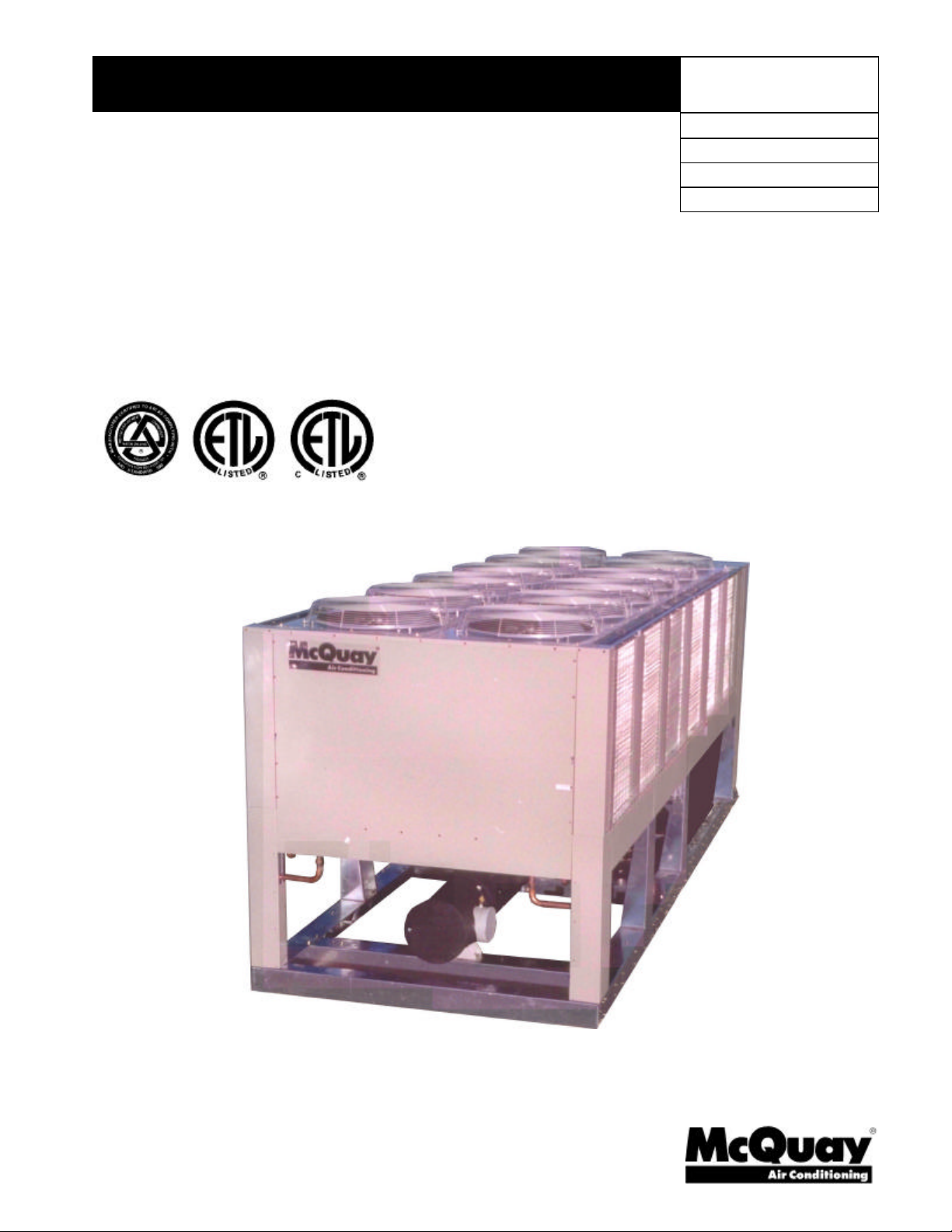
Packaged Air-Cooled Water Chiller
ALR 110F - ALR 150F
Refrigerant R-22, 60 Hertz
Group: Chiller
Part Number: 330145705
Effective: December 2000
Supersedes: IM ALR-1
© 1997 McQuay International
Page 2
Table of Contents
Introduction.................................................................................................................3
General Description..................................................................................................................................................3
Inspection..................................................................................................................................................................3
Installation.................................................................................................................................................................3
Handling....................................................................................................................................................................4
Installation and Application........................................................................................5
Location.....................................................................................................................................................................5
Vibration Isolators.....................................................................................................................................................7
Lifting and Mounting Weights...................................................................................................................................7
Water Piping..............................................................................................................................................................8
Refrigerant Charge...................................................................................................................................................10
Glycol Solutions......................................................................................................................................................10
Evaporator Water Flow and Pressure Drop............................................................................................................11
Variable Water Flow................................................................................................................................................11
Physical Data.............................................................................................................13
Electrical Data...........................................................................................................15
Field Wiring.............................................................................................................................................................15
Dimensional Data......................................................................................................23
Wind Baffles and Hail Guards..................................................................................24
Remote Evaporator...................................................................................................25
General....................................................................................................................................................................25
Dimensions, Remote Evaporator............................................................................................................................27
Unit Layout and Principles of Operation..................................................................28
Control Center.........................................................................................................................................................28
Start-up and Shutdown..............................................................................................29
Pre Start-up.............................................................................................................................................................29
Start-up ...................................................................................................................................................................29
Sequence of Operation............................................................................................................................................30
Unit Maintenance......................................................................................................31
Preventative Maintenance Schedule........................................................................................................................32
Refrigerant Charging................................................................................................................................................33
ALR Troubleshooting Chart ...................................................................................................................................34
"McQuay" is a registered trademarks of McQuay International
"Illustrations and data cover the McQuay International products at the time of publication and we reserve the right
to make changes in design and construction at anytime without notice"
2 ALR 110F through 150F IOMM ALR-2
1997 McQuay International
Page 3
Introduction
General Description
McQuay air-cooled water chillers are complete, self-contained, automatic refrigerating units. Every unit is
completely assembled, factory wired, charged, and tested. Each unit consists of twin air-cooled condensers with
integral subcooler sections, two accessible hermetic compressors per circuit, replaceable tube, dual circuit shelland-tube evaporator, and complete refrigerant piping. Liquid line components include manual liquid line shutoff
valves, sight-glass/moisture indicators, solenoid valves, and double diaphragm hydraulic element thermal
expansion valves. Other features include compressor crankcase heaters, an evaporator heater for chilled water
freeze protection, limited pumpdown during “on” or “off” periods, compressor lead-lag switch to alternate the
compressor starting sequence, and sequenced starting of compressors.
The electrical control center includes all safety and operating controls necessary for dependable automatic
operation. Condenser fan motors are fused in all three phases and started by their own three-pole contactors.
Compressors are protected by circuit breakers. Optional factory installed or field installed fused disconnect
switches are available.
Operator information on the standard UNT controller can be found in IOM UNT33n. Information on the
optional MicroTech control can be found in the latest version of OM-RCPMICRO.
Inspection
Check all items carefully against the bill of lading. Inspect all units for damage upon arrival. Report shipping
damage and file a claim with the carrier. Check the unit name plate before unloading, making certain it agrees with
the power supply available. McQuay is not responsible for physical damage after unit leaves the factory.
Note: Unit shipping and operating weights are available in the Physical Data tables beginning
on page 13.
Installation
Note: Installation is to be performed by qualified personnel who are familiar with local codes
and regulations.
WARNING
Sharp edges and coil surfaces are a potential hazard. Avoid contact with them.
IOMM ALR-2 ALR110F through 150F 3
Page 4

Handling
Be careful to avoid rough handling of the unit. Do not push or pull the unit from anything other than the base. Block the
pushing vehicle away from the unit to prevent damage to the sheet metal cabinet and end frame.
To lift the unit, 2 1/2" (64mm) diameter lifting holes are provided in the base of the unit. Arrange spreader bars and cables
to prevent damage to the condenser coils or cabinet (see Figure 2).
Figure 1, Suggested Pushing Arrangement
Figure 2, Required Lifting Arrangement
NOTES:
1. All four rigging points on a unit must be used. See Figure 5 for location, and weight at lifting points for a specific
size unit.
2. Crosswise and lengthwise spreader bars must be used to avoid damage to unit. Lifting cables from the unit
mounting holes up must be vertical.
3. The number of condenser fans can vary from this diagram.
4 ALR 110F through 150F IOMM ALR-2
Page 5

Installation and Application
Location
Unit Placement
ALR units are for outdoor applications and can be mounted on a roof or ground level. Set units on a solid and
level foundation. For roof mounted applications, install the unit on a steel channel or I-beam frame to support
the unit above the roof. For ground level applications, install the unit on a substantial base that will not settle. A
one piece concrete slab with footings extended below the frost line is recommended. Be sure the foundation is
level (within 1/2” [13 mm] over its length and width). The foundation must support the operating weights listed
in the Physical Data tables beginning on page 13.
On ground level applications protect the unit against vandalism by using the optional lower wire mesh guards or
by erecting a screen fence. The fence must allow free flow of air to the condenser coil for proper unit operation.
Clearances
The flow of air to and from the condenser coils must not be limited. Restricting air flow or allowing air
recirculation will result in a decrease in unit performance and efficiency. There must be no obstruction above the
unit that would deflect discharge air downward where it could be recirculated back to the inlet of the condenser
coil. The condenser fans are propeller type and will not operate with ductwork on the fan outlet.
Install the unit with enough side clearance for air entrance to the coil and for servicing. Provide service access to
the evaporator, compressors, electrical control panel and piping components as shown in Figure 3.
Do not allow debris to accumulate near the unit. Air movement may draw debris into the condenser coil causing
air starvation. Give special consideration to low ambient operation where snow can accumulate. Keep condenser
coils and fan discharge free of snow or other obstructions to permit adequate airflow.
Service Access
Each end of the unit must be accessible after installation for periodic service. Compressors, filter-driers, and
manual liquid line shutoff valves are accessible on each side of the unit adjacent to the control box. High
pressure, low pressure, and motor protector controls are on the compressor. Freezestats and cooler barrel
thermostats are near the cooler. Most other operational, safety and starting controls are located in the unit
control box.
The condenser fan and motors can be removed from the top of the unit.
IOMM ALR-2 ALR110F through 150F 5
Page 6
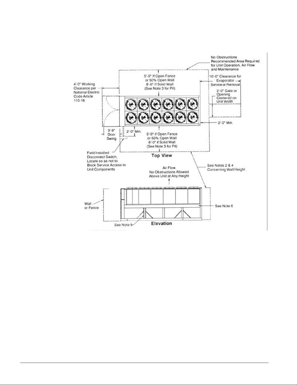
Figure 3, Clearance Requirements
Notes:
1. Minimum side clearance between two units is 12 feet.
2. Unit must not be installed in a pit or enclosure that is deeper or taller than the height of the unit unless extra
clearance is provided per note 4.
3. Minimum clearance on each side is 8 feet when installed in a pit no deeper than the unit height.
4. Minimum side clearance to a side wall or building taller than the unit height is 8 feet provided no solid wall
above 6 feet is closer than 12 feet to the opposite side of the unit.
5. The evaporator can be removed from the side of the unit.
6. Do not mount electrical conduits, etc, above the side rail on either side if the unit.
7. There must be no obstruction of the fan discharge.
Sound Isolation
The low sound level of the ALR reciprocating chiller is suitable for most applications. When additional sound
reduction is necessary, locate the unit away from sound sensitive areas. Avoid locations beneath windows or
between structures where normal operating sounds may be objectionable. Reduce structurally transmitted sound
by isolating water lines, electrical conduit and the unit itself. Use wall sleeves and rubber isolated piping hangers
to reduce transmission of water or pump noise into occupied spaces. Use flexible electrical conduit to isolate
sound through electrical conduit. Spring isolators are effective in reducing the low amplitude sound generated by
reciprocating compressors and for unit isolation in sound sensitive areas.
6 ALR 110F through 150F IOMM ALR-2
Page 7
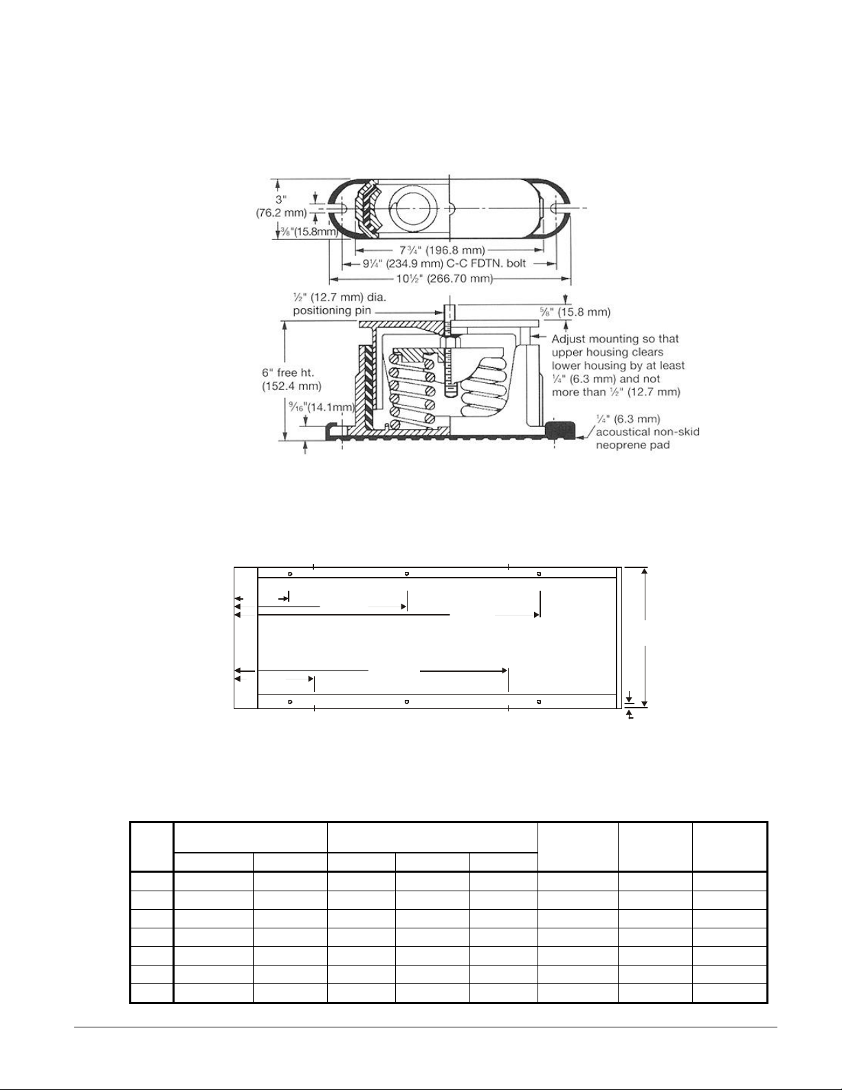
Vibration Isolators
Vibration isolators are recommended for all roof mounted installations or wherever vibration transmission is a
consideration.
Figure 4, Spring Flex Isolators
Lifting and Mounting Weights
Figure 5, ALR 110-150 Lifting and Mounting Locations
L2
ALR
Model
R2
36 (914)
BOX
CONTROL
46 (1168)
NOTES:
2 ½ in. (63.5 mm) lifting holes at location "L" on sides of base rails.
1 in. (25.4 mm) mounting holes at location "M" on bottom of base rails.
Lifting Weight for Each Point
102 (2591)
R1
L1
Mounting Loads for Each Point
lb (kg)
L1 & L2 L3 & L4 R1 & R2 R3 & R4 R5 & R6
R4
192 (4877)
161 (4089)
R3
lb. (kg)
110 2585 (1171) 2125 (963) 1835 (831) 1785 (809) 1230 (557) 9700 (4394) 9420 (4267) 1370 (620)
120 2570 (1164) 2205 (999) 1830 (829) 1805 (818) 1305 (591) 9880 (4476) 9550 (4326) 1370 (620)
130 2570 (1164) 2205 (999) 1830 (829) 1805 (818) 1305 (591) 9880 (4476) 9550 (4326) 1370 (620)
135 2570 (1164) 2205 (999) 1830 (829) 1805 (818) 1305 (591) 9880 (4476) 9550 (4326) 1370 (620)
140 2570 (1166) 2210 (1001) 1830 (829) 1805 (818) 1310 (593) 9890 (4478) 9560 (4340) 1370 (620)
145 2570 (1166) 2210 (1001) 1830 (829) 1805 (818) 1310 (593) 9890 (4480) 9560 (4330) 1370 (620)
150 2600 (1178) 2280 (1032) 1860 (842) 1840 (833) 1345 (609) 10090 (4571) 9760 (4421) 1370 (620)
L4
R6
83.4
(2118)
R5
L3
Operating Wt
lb. (kg)
2 (51)
Typical Spacing
for Isolator
Mounting (6)
Shipping Wt.
lb. (kg)
Copper Fin
Add
IOMM ALR-2 ALR110F through 150F 7
Page 8
Water Piping
Local authorities can supply the installer with the proper building and safety codes required for safe and proper
installation.
Install piping with minimum bends and changes in elevation to minimize pressure drop. Consider the following when
installing water piping:
1. Vibration eliminators to reduce vibration and noise transmission to the building.
2. Shutoff valves to isolate the unit from the piping system during unit servicing.
3. Manual or automatic air vent valves at the high points of the system. Install drains at the lowest points in
the system.
4. A means of maintaining adequate system water pressure (expansion tank or regulating valve).
5. Temperature and pressure indicators located at the unit to aid in unit servicing.
6. A strainer or other means of removing foreign matter from the water before it enters the pump. Place the
strainer far enough upstream to prevent cavitation at the pump inlet (consult pump manufacturer for
recommendations). The use of a strainer will prolong pump life and keep system performance up.
7. Place a strainer in the water line just before the inlet of the evaporator. This will help prevent foreign
material from entering and decreasing the performance of the evaporator.
CAUTION
If separate disconnect is used for the 110V supply to the evaporator heating cable, mark the
disconnect clearly to ensure disconnect is not accidentally shut off during cold seasons.
8. The shell-and-tube evaporator has a thermostat and heating cable to prevent freeze-up down to
-20°F (-29°C). It is suggested that the heating cable be wired to a separate 110V supply circuit. As
shipped from the factory, the heating cable is wired to the control circuit. All water piping to the unit must
also be protected to prevent freezing.
9. If the unit is used as a replacement chiller on a previously existing piping system, flush the system
thoroughly before unit installation. Regular water analysis and chemical water treatment on the evaporator
is recommended immediately at equipment start-up.
10. The total water quantity in the system should be sufficient to prevent frequent "on-off" cycling. For air-
conditioning systems, system gallons equal to 7 time the flow rate is recommended..
11. When glycol is added to the water system for freeze protection, the refrigerant suction pressure will be
lower, cooling performance less, and water side pressure drop greater. If the percentage of glycol is high, or
if propylene is used instead of ethylene glycol, the added pressure drop and loss of performance could be
substantial. Reset the freezestat and low leaving water alarm temperatures. The freezestat is factory set to
default at 36°F (2.2°C). Reset the freezestat setting to approximately 4 to 5 degrees F (2.3 to 2.8 degrees
C) below the leaving chilled water setpoint temperature. See the section titled “Glycol Solutions” for
additional information concerning glycol.
12. Perform a preliminary leak check before insulating the piping and filling the system.
13. Piping insulation should include a vapor barrier to prevent condensation and possible damage to the building
structure.
8 ALR 110F through 150F IOMM ALR-2
Page 9
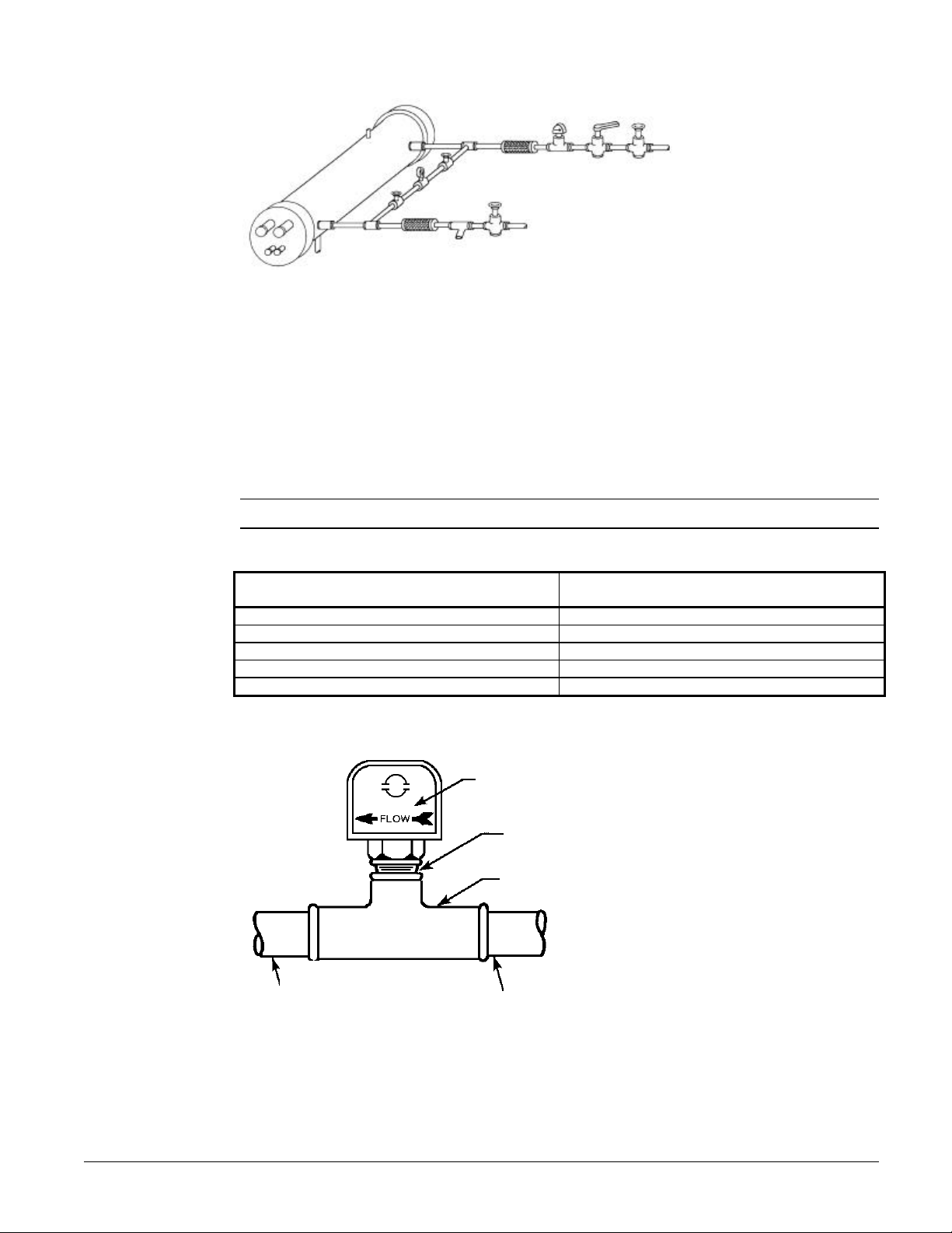
Figure 6, Typical Evaporator Water Piping
Vent
Outlet
Valved
pressure
gauge
Vibration
Eliminator
Flow
Switch
Balancing
valve
Gate valve
Protect all field piping
against freezing
Drain
Vibration
Eliminator
Water
strainer
Gate valve
Flow Switch
Mount a water flow switch in either the entering or leaving water line to shut down the unit when water flow is
interrupted.
A flow switch is available from McQuay (part number 017503300). It is a “paddle” type switch and adaptable
to any pipe size from 3” (76mm) to 8” (203mm) nominal. Certain minimum flow rates are required to close the
switch and are listed in Table 1. Installation should be as shown in Figure 7. Connect the normally open
contacts of the flow switch in the unit control center at terminals 5 and 6. There is also a set of normally closed
contacts on the switch that can be used for an indicator light or an alarm to indicate when a “no flow” condition
exists. Freeze protect any flow switch that is installed outdoors.
NOTE: Differential pressure switches are not recommended for outdoor installation.
Table 1, Flow Switch Minimum Flow Rates
NOMINAL PIPE SIZE MINIMUM REQUIRED FLOW TO
INCHES (MM) ACTIVATE SWITCH - GPM (L/s)
3 (76.20) 30 (1.9)
4 (101.6) 39 (2.5)
5 (127.0) 59 (3.7)
6 (152.4) 79 (5.0)
8 (203.0) 140 (8.8)
Figure 7, Flow Switch Installation
Flow direction
marked on switch
1" (25mm) NPT flow
switch connection
Tee
1 1/4" (32mm) pipe
dia. min. after
switch
1 1/4" (32mm) pipe
dia. min. before switch
Water Connections
Bring water piping to the evaporator from the bottom of the unit or through the side between the vertical
supports.
IOMM ALR-2 ALR110F through 150F 9
Page 10
Note: The procedure
does not specify the
type of glycol. Use
the derate factors
found in Table 2 for
corrections when
using ethylene glycol
and those in Table 3
for propylene glycol.
Refrigerant Charge
All units designed for use with HCFC-22 are shipped with an operating charge (remote evaporator applications
are shipped with a unit operating charge and may require additional charge for field piping). The operating charge
(using HCFC-22) for each unit is shown in the Physical Data tables beginning on page 13.
Glycol Solutions
The system glycol capacity, glycol solution flow rate, and pressure drop through the cooler may be calculated
using the following formulas and Table 4.
1. Capacity -- Find the reduced capacity by multiplying the chiller capacity with water by the capacity
correction factor "Cap".
2. Flow -- To determine evaporator flow (or Delta-T) knowing Delta-T (or GPM) and capacity:
)(24
GPM Glycol FactorFlow
×
=
For Metric Applications -- To determine evaporator L/s (or Delta-T) knowing Delta-T (or L/s) and kW:
L/s Glycol FactorFlow
=
kW
18.4
3. Pressure drop -- To determine pressure drop through the evaporator, when using glycol, enter the water
pressure drop curve on page 12 at the water flow. Multiply the water pressure drop by "PD" correction
factor from Table 2 or Table 3 to obtain corrected glycol pressure drop.
4. To determine the unit's power consumption when using glycol, multiply the water system kW by glycol
factor "kW".
Test coolant with a clean, accurate glycol solution hydrometer (similar to that found in service stations) to
determine the freezing point. Obtain the percent glycol from the freezing point table below. It is normally
recommended by the supplier that a minimum of 25% glycol solution by weight be used for protection against
corrosion.
glycolcapacity
TDelta
−
×
TDelta
−×
×
2,3) table(from
2,3) table(from
CAUTION
Do not use automotive grade antifreeze. Industrial grade glycols must be used. Automotive
antifreeze contains inhibitors that will cause plating on the copper
tubes within the chiller evaporator. The type and handling of glycol used
must be consistent with local codes.
Table 2, Ethylene Glycol
% Freeze Point
E.G. °F °C Cap. kW Flow PD
10 26 -3 0.991 0.996 1.013 1.070
20 18 -8 0.982 0.992 1.040 1.129
30 7 -14 0.972 0.986 1.074 1.181
40 -7 -22 0.961 0.976 1.121 1.263
50 -28 -33 0.946 0.966 1.178 1.308
Table 3, Propylene Glycol
% Freeze Point
P.G. °F °C Cap. kW Flow PD
10 26 -3 0.987 0.992 1.010 1.068
20 19 -7 0.975 0.985 1.028 1.147
30 9 -13 0.962 0.978 1.050 1.248
40 -5 -21 0.946 0.971 1.078 1.366
50 -27 -33 0.929 0.965 1.116 1.481
10 ALR 110F through 150F IOMM ALR-2
Page 11
Table 4, Capacity and Power Derates
SEA
LEVEL
2000 feet
(610 m)
4000 feet
(1220 m)
6000 feet
(1830 m)
Water
Delta-T
°F °C Cap. Power Cap. Power Cap. Power Cap. Power
6 3.3 0.992 0.995 0.985 0.993 0.962 0.986 0.919 0.972
8 4.4 0.995 0.997 0.988 0.995 0.965 0.988 0.922 0.974
10 5.6 1.000 1.000 0.993 0.998 0.970 0.991 0.927 0.977
12 6.7 1.005 1.002 0.998 1.000 0.975 0.993 0.932 0.979
14 6.8 1.010 1.005 1.003 1.003 0.980 0.996 0.936 0.982
16 8.9 1.014 1.007 1.007 1.005 0.984 0.998 0.940 0.984
6 3.3 0.978 1.005 0.971 1.003 0.949 0.996 0.906 0.982
8 4.4 0.982 1.007 0.975 1.005 0.953 0.998 0.910 0.984
10 5.6 0.986 1.009 0.979 1.007 0.956 1.000 0.914 0.986
12 6.7 0.992 1.011 0.985 1.009 0.962 1.002 0.919 0.988
14 6.8 0.997 1.014 0.990 1.012 0.967 1.005 0.924 0.991
16 8.9 1.000 1.016 0.993 1.014 0.970 1.007 0.927 0.993
6 3.3 0.966 1.016 0.959 1.014 0.937 1.007 0.895 0.993
8 4.4 0.969 1.018 0.962 1.016 0.940 1.009 0.898 0.995
10 5.6 0.973 1.021 0.966 1.019 0.944 1.012 0.902 0.998
12 6.7 0.978 1.025 0.971 1.023 0.949 1.016 0.906 1.002
14 6.8 0.982 1.027 0.975 1.025 0.953 1.018 0.910 1.004
16 8.9 0.986 1.028 0.979 1.026 0.956 1.019 0.914 1.005
6 3.3 0.953 1.025 0.946 1.023 0.924 1.016 0.883 1.002
8 4.4 0.955 1.028 0.948 1.026 0.926 1.019 0.885 1.005
10 5.6 0.959 1.031 0.952 1.029 0.930 1.022 0.889 1.008
12 6.7 0.963 1.034 0.956 1.032 0.934 1.024 0.893 1.011
14 6.8 0.968 1.036 0.961 1.034 0.939 1.026 0.897 1.013
16 8.9 0.972 1.037 0.965 1.035 0.943 1.027 0.901 1.014
0.0001 (0.0176) 0.00025 (0.044) 0.00075 (0.132) 0.00175 (0.308)ALTITUDE
Fouling FactorChilled
Evaporator Water Flow and Pressure Drop
Evaporator flow rate must fall between the minimum and maximum values shown in the evaporator pressure
drop curve. Flow rates below the minimum values will result in laminar flow that will reduce efficiency, cause
erratic operation of the expansion valve and could cause low temperature cutouts. Flow rates exceeding the
maximum values can cause erosion on the evaporator water connections and tubes.
Measure the chilled water pressure drop through the evaporator at field installed pressure taps. It is important
not to include the effect of valves or strainers in these readings.
Variable Water Flow
Variable water flow involves changing the water flow through the evaporator as the load changes. McQuay
chillers are designed for this duty provided that the rate of change in water flow is slow and the minimum and
maximum flow rates for the vessel are not exceeded.
Ten percent is the maximum allowable percent per minute change of flow. The ALR control logic has timers that
limit the rate of unloading or loading allowed. Slow changes allow the chiller the opportunity to sense a change,
react to the change and stabilize preventing operational problems.
IOMM ALR-2 ALR110F through 150F 11
Page 12

Figure 8, Evaporator Water Pressure Drops
ALR 110
ALR 145 - 150
ALR 120 - 140
Table 5, Minimum/Maximum Flow Rates
ALR Unit
Size
110 165 (10.4) 6.0 (17.9) 435 (27.4) 39.0 (116.0)
120 180 (11.4) 4.3 (12.8) 480 (30.3) 30.5 (90.0)
130 195 (12.3) 5.1 (15.2) 520 (32.8) 37.5 (111.8)
135 200 (12.6) 5.3 (15.8) 535 (33.8) 40.0 (119.2)
140 205 (13.0) 5.8 (17.3) 550 (34.7) 42.0 (125.2)
145 215 (13.6) 4.3 (12.8) 570 (36.0) 29.5 (87.9)
150 220 (13.9) 4.5 (13.4) 590 (37.2) 31.0 (92.4)
Minimum
Flow gpm
(l/s)
Pressure
Drop
ft. (kPa)
Maximum Flow
gpm (l/s)
Pressure
Drop ft. (kPa)
12 ALR 110F through 150F IOMM ALR-2
Page 13

Physical Data
Table 6 , Physical Data ALR 110F through 135F
PHYSICAL DATA
BASIC DATA Ckt.1 Ckt.2 Ckt.1 Ckt.2 Ckt.1 Ckt.2 Ckt.1 Ckt.2
Unit Capacity @ ARI Conditions, Tons (kW)
(1)
Number Of Refrigerant Circuits 2 2 2 2
Unit Operating Charge, R-22, lbs. 115 115 120 120 120 120 120 120
Unit Operating Charge, R-22, (kg) (52.1) (52.1) (54.4) (54.4) (54.4) (54.4) (54.4) (54.4)
Cabinet Dimensions, LxWxH, in. 229 x 83 x 89 229 x 83 x 89 229 x 83 x 89 229 x 83 x 89
Cabinet Dimensions, LxWxH, (mm)
Unit Operating Weight, lbs. (kg) 9700 (4394) 9880 (4476) 9880 (4476) 9880 (4476)
Unit Shipping Weight, lbs. (kg) 9420 (4267) 9550 (4326) 9550 (4326) 9550 (4326)
Add'l Weight If Copper Finned Coils, lbs. (kg) 1370 (620) 1370 (620) 1370 (620) 1370 (620)
COMPRESSORS
Type Semi-Hermetic Semi-Hermetic Semi-Hermetic Semi-Hermetic
Nominal Horsepower 30-30 30-35 30-35 35-35 35-35 35-35 35-40 35-40
Number Of Cylinders Per Compressor 6 - 6 6 - 6 6 - 6 6 - 6 6 - 6 6 - 6 6 - 6 6 - 6
Oil Charge Per Compressor, oz. 140 - 140 140 - 140 140 - 140 140 - 140 140 - 140 140 - 140 140 - 255 140 - 255
Oil Charge Per Compressor, (l) (4.1-4.1) (4.1–4.1) (4.1–4.1) (4.1–4.1) (4.1–4.1) (4.1–4.1) (4.1–6.5) (4.1–6.5)
CAPACITY REDUCTION STEPS - PERCENT OF COMPRESSOR DISPLACEMENT
Staging - Circuit #1 in Lead 0-16-32-40-48 0-15-32-39-48 0-17-33-42-50 0-16-32-40-48
Staging - Circuit #2 in Lead 0-16-32-40-48 0-17-32-41-48 0-17-33-42-50 0-16-32-40-48
CONDENSERS - HIGH EFFICIENCY FIN AND TUBE TYPE WITH INTEGRAL SUBCOOLING
Coil Face Area, sq. ft. 115 115 115 115 115 115 115 115
Coil Face Area, (m2) (10.3) (10.3) (10.3) (10.3) (10.3) (10.3) (10.3) (10.3)
Finned Height x Finned Length, in. 80 x 208 80 x 208 80 x 208 80 x 208 80 x 208 80 x 208 80 x 208 80 x 208
Finned Height x Finned Length, (mm)
Fins Per Inch x Rows Deep 16 x 3 16 x 3 16 x 3 16 x 3 16 x 3 16 x 3 16 x 3 16 x 3
Maximum Relief Valve Pressure Setting, psig
(kPa)
CONDENSER FANS - DIRECT DRIVE PROPELLER TYPE
Number Of Fans - Fan Diameter, In. (mm) 10 - 28 (711) 10 - 28 (711) 12 - 28 (711) 12 - 28 (711)
Number Of Motors - HP (kW) 10 - 1.5 (1.1) 10 - 1.5 (1.1) 12 - 1.5 (1.1) 12 - 1.5 (1.1)
Fan And Motor RPM, 60 Hz 1140 1140 1140 1140
60 Hz Fan Tip Speed, fpm 8357 8357 8357 8357
60 Hz Total Unit Airflow, cfm 90200 90200 108240 108240
DIRECT EXPANSION EVAPORATOR - BAFFLED SHELL AND THRU-TUBE
Diameter, in. - Length, in. 12.8 x 94.6 14.0 x 95.5 14.0 x 95.5 14.0 x 95.5
Diameter, (mm) - Length, (mm) 325 x 2403 356 x 2426 356 x 2426 356 x 2426
Water Volume, Gallons, (L) 34 (127) 40 (150) 40 (150) 40 (150)
Maximum Water Pressure, psig (kPa) 152 (1047) 152 (1047) 152 (1047) 152 (1047)
Maximum Refrigerant Working Pressure, psig
(kPa)
Water Inlet / Outlet Victaulic Connections, in.
(mm)
Drain - NPT int, in. (mm) .5 (12.7) .5 (12.7) .5 (12.7) .5 (12.7)
Vent - NPT int, in. (mm) .5 (12.7) .5 (12.7) .5 (12.7) .5 (12.7)
NOTE:
1. Nominal capacity based on 95°F ambient air and 54°F/44°F water range.
110F 120F 130F 135F
110.9 (388.1) 122.2 (427.7) 129.6 (453.6) 133.7 (468.0)
(5809 x 2118 x
2210)
64-84-92-100 67-84-91-100 67-83-92-100 66-84-92-100
8-84-92-100 5-84-91-100 67-83-92-100 66-84-92-100
(2032 x
5283)
450
(3103)
(2032 x
5283)
450
(3103)
300 (2066) 300 (2066) 300 (2066) 300 (2066)
5 (127) 8 (203) 8 (203) 8 (203)
(2032 x
5283)
(3103)
ALR MODEL NUMBER
(5809 x 2118 x
2210)
(2032 x
5283)
450
450
(3103)
(5809 x 2118 x
2210)
(2032 x
5283)
(3103)
(2032 x
450
(3103)
5283)
450
(5817 x 2118 x
2210)
(2032 x
5283)
450
(3103)
(2032 x
5283)
450
(3103)
IOMM ALR-2 ALR110F through 150F 13
Page 14

Table 7, Physical Data ALR 140F through 150F
PHYSICAL DATA
140F 145F 150F
BASIC DATA Ckt.1 Ckt.2 Ckt.1 Ckt.2 Ckt.1 Ckt.2
Unit Capacity @ ARI Conditions (1), Tons (kW) 139.7 (489.0) 143.2 (501.2) 149.5 (523.3)
Number Of Refrigerant Circuits 2 2 2
Unit Operating Charge, R-22, lbs. 125 125 130 130 130 130
Unit Operating Charge, R-22, (kg) (56.6) (56.6) (58.9) (58.9) (58.9) (58.9)
Cabinet Dimensions, LxWxH, in. 229 x 83 x 89 229 x 83 x 89 229 x 83 x 89
Cabinet Dimensions, LxWxH, (mm) (5817 x 2118 x 2210) (5817 x 2118 x 2210) (5817 x 2118 x 2210)
Unit Operating Weight, Lbs. (kg) 9885 (4478) 9890 (4480) 10090 (4571)
Unit Shipping Weight, Lbs. (kg) 9555 (4328) 9560 (4330) 9760 (4421)
Add'l Weight If Copper Finned Coils, lbs. (kg) 1370 (620) 1370 (621) 1370 (621)
COMPRESSORS
Type Semi-Hermetic Semi-Hermetic Semi-Hermetic
Nominal Horsepower 40-40 40-40 40-40 40-40 40-40 40-50
Number Of Cylinders Per Compressor 6 - 6 6 - 6 6 - 6 6 - 6 6 - 6 6 - 8
Oil Charge Per Compressor, oz. 255 - 255 255 - 255 255 - 255 255 - 255 255 - 255 255 - 255
Oil Charge Per Compressor, (l) (6.5 – 6.5) (6.5 – 6.5) (6.5 – 6.5) (6.5 – 6.5) (6.5 – 6.5) (6.5 – 6.5)
CAPACITY REDUCTION STEPS - PERCENT OF COMPRESSOR DISPLACEMENT
Staging - Circuit #1 in Lead 0-17-33-42-50 0-17-33-42-50 0-15-32-40-64
67-83-92-100 67-83-92-100 64-84-92-100
Staging - Circuit #2 in Lead 0-17-33-42-50 0-17-33-42-50 0-15-32-40-48
67-83-92-100 67-83-92-100 68-84-92-100
CONDENSERS - HIGH EFFICIENCY FIN AND TUBE TYPE WITH INTEGRAL SUBCOOLING
Coil Face Area,Sq. Ft. 115 115 115 115 115 115
Coil Face Area, (m2) (10.3) (10.3) (10.3) (10.3) (10.3) (10.3)
Finned Height x Finned Length, in. 80 x 208 80 x 208 80 x 208 80 x 208 80 x 208 80 x 208
Finned Height x Finned Length, (mm)
(2032 x
5283)
(2032 x
5283)
Fins Per Inch x Rows Deep 16 x 3 16 x 3 16 x 3 16 x 3 16 x 3 16 x 3
Maximum Relief Valve Pressure Setting, psig
(kPa)
450
(3103)
450
(3103)
CONDENSER FANS - DIRECT DRIVE PROPELLER TYPE
Number Of Fans - Fan Diameter, In. (mm) 12 - 28 (711) 12 - 28 (711) 12 - 28 (711)
Number Of Motors - HP (kW) 12 - 1.5 (1.1) 12 - 1.5 (1.1) 12 - 1.5 (1.1)
Fan And Motor RPM, 60 HZ 1140 1140 1140
60 Hz Fan Tip Speed, fpm 8357 8357 8357
60 Hz Total Unit Airflow, cfm 108240 108240 108240
DIRECT EXPANSION EVAPORATOR - BAFFLED SHELL AND THRU-TUBE
Diameter, in. - Length, in. 14.0 x 95.5 16.0 x 96.8 16.0 x 96.8
Diameter, (mm) - Length, (mm) 356 x 2426 406 x 2459 406 x 2459
Water Volume, Gallons, (L) 40 (150) 55 (208) 55 (208)
Maximum Water Pressure, psig (kPa) 152 (1047) 152 (1047) 152 (1047)
Maximum Refrigerant Working Pressure, psig
(kPa)
Water Inlet / Outlet Victaulic Connections, in.
(mm)
300 (2066) 300 (2066) 300 (2066)
8 (203) 8 (203) 8 (203)
Drain - NPT int, in. (mm) .5 (12.7) .5 (12.7) .5 (12.7)
Vent - NPT int, in. (mm) .5 (12.7) .5 (12.7) .5 (12.7)
NOTE:
1. Nominal capacity based on 95°F ambient air and 54°F/44°F water range.
ALR MODEL
(2032 x
5283)
450
(3103)
(2032 x
5283)
450
(3103)
(2032 x
5283)
450
(3103)
(2032 x
5283)
450
(3103)
14 ALR 110F through 150F IOMM ALR-2
Page 15

Electrical Data
20861
4.00 (102)
600
230
4926350
1
4.00 (102)
600
600
460
2483250
1
2.50 (64)
300
300
575
18833/0
1
2.00 (51)
200
225
20861
4.00 (102)
600
230
5266400
1
4.00 (102)
600
500
460
2743300
1
2.50 (64)
300
300
575
20034/0
1
2.00 (51)
225
225
20861
4.00 (102)
700
230
5546500
1
4.00 (102)
600
600
460
2933350
1
2.50 (64)
300
350
575
21034/0
1
2.00 (51)
225
250
20862
2.50 (64)
700
230
5906350
2
2.50 (64)
700
700
460
3023350
1
2.50 (64)
350
350
575
22434/0
1
2.00 (51)
250
250
20862
3.00 (76)
700
230
6226400
2
3.00 (76)
700
700
460
3103400
1
2.50 (64)
350
350
575
2363250
1
2.50 (64)
250
250
20862
3.00 (76)
700
230
6226400
2
3.00 (76)
700
700
460
3103400
1
2.50 (64)
350
350
575
2363250
1
2.50 (64)
250
250
20862
3.00 (76)
800
230
6666500
2
3.00 (76)
800
800
460
3343400
1
3.00 (76)
350
400
575
2613300
1
2.50 (64)
300
300
Field Wiring
CAUTION
Internal power wiring to the compressors for single and multiple point option
are different. Field wiring must be installed according to unit wiring diagram.
Wiring must comply with all applicable codes and ordinances. Warranty is void if wiring is not in accordance with
specifications. Copper wire is required for all power lead terminations at the unit. Aluminum or copper can be used for
all other wiring.
ALR units may be ordered with internal power wiring for either single or multiple point power connection. If single point
power connection is ordered, a single large power terminal block is provided and wiring within the unit is sized in
accordance with the National Electrical Code. A single field supplied fused disconnect is required. If multiple point power
wiring is ordered, three power connections, one per compressor circuit, one for condenser fans, and control circuit, are
required. Separate field supplied fused disconnects are required for each of the three circuits. A single power block is
provided for all of the condenser fans and the 115V control transformer.
If the evaporator heater is on a separate disconnect switch from the main unit power supply, the unit may be shut down
without defeating the freeze protection provided by the cooler heater.
Table 8, ALR 110F – 150F Electrical Data, Single Point
Field Wire Hub (Conduit Connection) Fuse or HACR Breaker SizeALR
Quantity Wire Gauge Quantity Size Recommended Maximum
Unit
Size
Volts Hz
Min. Circuit
Ampacity
(MCA)
110F
120F
130F
135F
140F
145F
150F
1. See page 21 for all Electrical Data notes.
2. A “HACR” breaker is designed for use on equipment with multiple motors. It stands for Heating, Air Conditioning,
Refrigeration
60
60
60
60
60
60
60
IOMM ALR-2 ALR 110F through 150F 15
Page 16

Table 9, ALR 110F – 150F Electrical Data, Multiple Point
ALR
Unit
Size
110F
120F
130F
135F
140F
145F
150F
Min.
Ckt.
Volts
Amp
MCA
208 60 3 6 1
230 60 3 6 1
460 29 3 10 1
575 24 3 10 1
208 60 3 6 1
230 60 3 6 1
460 29 3 10 1
575 24 3 10 1
208 71 3 4 1
230 71 3 4 1
460 35 3 8 1
575 28 3 10 1
208 71 3 4 1
230 71 3 4 1
460 35 3 8 1
575 28 3 10 1
208 71 3 4 1
230 71 3 4 1
460 35 3 8 1
575 28 3 10 1
208 71 3 4 1
230 71 3 4 1
460 35 3 8 1
575 28 3 10 1
208 71 3 4 1
230 71 3 4 1
460 35 3 8 1
575 28 3 10 1
Power Supply
Fans and Controls
Field Wire Hub Field Wire Hub Field Wire Hub
Wire
Qty.
Size
Qty.
Hub
Size
1.50
(38)
1.50
(38)
1.00
(25)
1.00
(25)
1.50
(38)
1.50
(38)
1.00
(25)
1.00
(25)
2.00
(51)
2.00
(51)
1.25
(32)
1.00
(25)
2.00
(51)
2.00
(51)
1.25
(32)
1.00
(25)
2.00
(51)
2.00
(51)
1.25
(32)
1.00
(25)
2.00
(51)
2.00
(51)
1.25
(32)
1.00
(25)
2.00
(51)
2.00
(51)
1.25
(32)
1.00
(25)
Field
Fusing(1)
Rec.
Fuse
Size
60 60
60 60
30 30
25 25
60 60
60 60
30 30
25 25
80 80
80 80
35 35
30 30
80 80
80 80
35 35
30 30
80 80
80 80
35 35
30 30
80 80
80 80
35 35
30 30
80 80
80 80
35 35
30 30
Max.
Fuse
Size
Min.
Ckt
Amp
MCA
218
218
108
83
251
240
124
91
277
257
137
97
296
277
142
104
311
293
146
110
311
293
146
110
311
293
146
110
Power Supply
Circuit #1
Wire
Qty.
Size
3
4/0
3
4/0
3
2
3
4
3
250
3
250
3
1
3
3
3
300
3
300
3
1/0
3
3
3
350
3
300
3
1/0
3
2
3
400
3
350
3
1/0
3
2
3
400
3
350
3
1/0
3
2
3
400
3
350
3
1/0
3
2
Qty
Field
Fusing (1)
Rec.
Fuse
Hub
Size
Size
2.00
1
1
1
1
1
1
1
1
1
1
1
1
1
1
1
1
1
1
1
1
1
1
1
1
1
1
1
1
(51)
2.00
(51)
1.25
(32)
1.00
(25)
2.50
(64)
2.50
(64)
1.25
(32)
1.25
(32)
2.50
(64)
2.50
(64)
1.50
(38)
1.25
(32)
2.50
(64)
2.50
(64)
1.50
(38)
1.25
(32)
2.50
(64)
2.50
(64)
1.50
(38)
1.25
(32)
2.50
(64)
2.50
(64)
1.50
(38)
1.25
(32)
2.50
(64)
2.50
(64)
1.50
(38)
1.25
(32)
250 300 251
250 300 240
125 150 124
100 110 91
300 300 277
300 300 257
150 150 137
110 125 97
350 400 277
300 350 257
175 175 137
110 125 97
350 400 296
350 350 277
175 200 142
125 125 104
350 400 311
350 400 293
175 200 146
125 150 110
350 400 311
350 400 293
175 200 146
125 150 110
350 400 344
350 400 336
175 200 170
125 150 135
Max.
Fuse
Size
Min.
Ckt
Amp
MCA
Power Supply
Circuit #2
Wire
Qty.
Size
3
250
3
250
3
1
3
3
3
300
3
300
3
1/0
3
3
3
300
3
300
3
1/0
3
3
3
350
3
300
3
1/0
3
2
3
400
3
350
3
1/0
3
2
3
400
3
350
3
1/0
3
2
3
500
3
500
3
2/0
3
1/0
Qty.
1
1
1
1
1
1
1
1
1
1
1
1
1
1
1
1
1
1
1
1
1
1
1
1
1
1
1
1
Hub
Size
2.50
(64)
2.50
(64)
1.25
(32)
1.25
(32)
2.50
(64)
2.50
(64)
1.50
(38)
1.25
(32)
2.50
(64)
2.50
(64)
1.50
(38)
1.25
(32)
2.50
(64)
2.50
(64)
1.50
(38)
1.25
(32)
3.00
(76)
2.50
(64)
1.50
(38)
1.25
(32)
3.00
(76)
2.50
(64)
1.50
(38)
1.25
(32)
3.00
(76)
3.00
(76)
2.00
(51)
1.50
(38)
Field
Fusing (1)
Rec.
Max.
Fuse
Fuse
Size
Size
300 350
225 350
150 175
110 125
300 400
250 350
175 175
110 125
300 400
250 350
175 175
110 125
350 400
300 400
175 200
125 150
350 400
300 400
175 200
125 150
350 400
300 400
175 200
125 150
400 500
350 500
200 250
175 200
16 ALR 110F through 150F IOMM ALR-2
Page 17

Table 10, ALR 110F –150F Compressor and Condenser Fan Motor Amp Draw
ALR
Unit
Volts
Size
208
230
110F
460
575
208
230
120F
460
575
208
123 123 123 123
230
130F
135F
140F
145F
150F
See page 21 for all Electrical Data notes.
114 114 114 114
460
575
208
123 123 138 138
230
114 114 130 130
460
575
208
138 138 138 138
230
130 130 130 130
460
575
208
138 138 138 138
230
130 130 130 130
460
575
208
138 138 138 165
230
130 130 130 165
460
575
Rated Load Amps Locked Rotor Amps
Compressors Compressors
No.1No.2No.3No.
97 97 97 123
97 97 97 114
48 48 48 61
37 37 37 43
97 123 123 123
97 114 114 114
48 61 61 61
37 43 43 43
61 61 61 61
43 43 43 43
61 61 65 65
43 43 49 49
65 65 65 65
49 49 49 49
65 65 65 65
49 49 49 49
65 65 65 84
49 49 49 69
Motors
(Each)
4
No.
Fan
5.8 10 23.7 565 565 565 650 340 340 340 400
5.8 10 21.4 565 565 565 594 340 340 340 340
2.8 10 10.7 283 283 283 297 156 156 156 195
2.3 10 11.5 230 230 230 245 138 138 138 152
5.8 10 23.7 565 650 650 650 340 400 400 400
5.8 10 21.4 565 594 594 594 340 340 340 340
2.8 10 10.7 283 297 297 297 156 195 195 195
2.3 10 11.5 230 245 245 245 138 152 152 152
5.8 12 23.7 650 650 650 650 400 400 400 400
5.8 12 21.4 594 594 594 594 340 340 340 340
2.8 12 10.7 297 297 297 297 195 195 195 195
2.3 12 11.5 245 245 245 245 152 152 152 152
5.8 12 23.7 650 650 754 754 400 400 463 463
5.8 12 21.4 594 594 594 594 340 340 340 340
2.8 12 10.7 297 297 297 297 195 195 195 195
2.3 12 11.5 245 245 245 245 152 152 152 152
5.8 12 23.7 754 754 754 754 463 463 463 463
5.8 12 21.4 594 594 594 594 340 340 340 340
2.8 12 10.7 297 297 297 297 195 195 195 195
2.3 12 11.5 245 245 245 245 152 152 152 152
5.8 12 23.7 754 754 754 754 463 463 463 463
5.8 12 21.4 594 594 594 594 340 340 340 340
2.8 12 10.7 297 297 297 297 195 195 195 195
2.3 12 11.5 245 245 245 245 152 152 152 152
5.8 12 23.7 754 754 754 1070 463 463 463 654
5.8 12 21.4 594 594 594 1070 340 340 340 654
2.8 12 10.7 297 297 297 510 195 195 195 330
2.3 12 11.5 245 245 245 405 152 152 152 262
Of
Fan
Motor
Fan
Motors
(Each)
Across-The-Line Reduced Inrush
No. 1 No. 2 No. 3 No. 4 No. 1 No. 2 No. 3 No. 4
IOMM ALR-2 ALR 110F through 150F 17
Page 18

Table 11, ALR 110F – 150F Field Wiring Data, Single Point Power
ALR
Unit
Size
110F
120F
130F
135F
140F
145F
150F
See page 21 for all other Electrical Data notes.
Volts
208 840 (2 qty.) 1/0 - 600 MCM 600 (2 qty.) 400 - 500 MCM
230 840 (2 qty.) 1/0 - 600 MCM 600 (2 qty.) 250 - 350 MCM
460 380 (1 qty.) #4 - 500 MCM 400 (1 qty.) 250 - 500 MCM
575 380 (1 qty.) #4 - 500 MCM 250 (1qty.) #4 - 350 MCM
208 840 (2 qty.) 1/0 - 600 MCM 600 (2 qty.) 250 - 500 MCM
230 840 (2 qty.) 1/0 - 600 MCM 600 (2 qty.) 400 - 500 MCM
460 380 (1 qty.) #4 - 500 MCM 400 (1 qty.) 250 - 500 MCM
575 380 (1 qty.) #4 - 500 MCM 250 (1qty.) #4 - 350 MCM
208 840 (2 qty.) 1/0 - 600 MCM 800 (2 qty.) 500 - 700 MCM
230 840 (2 qty.) 1/0 - 600 MCM 800 (2 qty.) 500 - 700 MCM
460 380 (1 qty.) #4 - 500 MCM 400 (1 qty.) 250 - 500 MCM
575 380 (1 qty.) #4 - 500 MCM 250 (1qty.) #4 - 350 MCM
208 840 (2 qty.) 1/0 - 600 MCM 800 (2 qty.) 500 - 700 MCM
230 840 (2 qty.) 1/0 - 600 MCM 800 (3 qty.) 3/0 - 400 MCM
460 380 (1 qty.) #4 - 500 MCM 400 (1 qty.) 250 - 500 MCM
575 380 (1 qty.) #4 - 500 MCM 250 (1qty.) #4 - 350 MCM
208 840 (2 qty.) 1/0 - 600 MCM 800 (2 qty.) 500 - 700 MCM
230 840 (2 qty.) 1/0 - 600 MCM 800 (2 qty.) 500 - 700 MCM
460 380 (1 qty.) #4 - 500 MCM 400 (1 qty.) 250 - 500 MCM
575 380 (1 qty.) #4 - 500 MCM 400 (1 qty.) 250 - 500 MCM
208 840 (2 qty.) 1/0 - 600 MCM 800 (2 qty.) 500 - 700 MCM
230 840 (2 qty.) 1/0 - 600 MCM 800 (2 qty.) 500 - 700 MCM
460 380 (1 qty.) #4 - 500 MCM 400 (1 qty.) 250 - 500 MCM
575 380 (1 qty.) #4 - 500 MCM 400 (1 qty.) 250 - 500 MCM
208 840 (4 qty.) 1/0 - 600 MCM 800 (2 qty.) 500 - 700 MCM
230 840 (4 qty.) 1/0 - 600 MCM 800 (2 qty.) 500 - 700 MCM
460 840 (2 qty.) 1/0 - 600 MCM 400 (1 qty.) 250 - 500 MCM
575 840 (2 qty.) 1/0 - 600 MCM 400 (1 qty.) 250 - 500 MCM
Terminal
Amps
Wiring to
Standard Power Block
Connector Wire Range/Phase
(Copper Wire Only)
Terminal
Amps
Wiring to Optional Factory Mounted
Disconnect Switch
Connector Wire Range/Phase
(Copper Wire Only)
18 ALR 110F through 150F IOMM ALR-2
Page 19

Table 12, ALR 110F – 150F, Field Wiring Data, Multiple Point Power with Power Blocks
ALR
Unit
Size
110F
120F
130F
135F
140F
145F
150F
See page 21 for all Electrical Data notes.
Volts
208 175 380 380 (1 qty.) #12 - 2/0 (1 qty.) #4 - 400 MCM (1 qty.) #4 - 400 MCM
230 175 380 380 (1 qty.) #12 - 2/0 (1 qty.) #4 - 400 MCM (1 qty.) #4 - 400 MCM
460 175 175 175 (1 qty.) #12 - 2/0 (1 qty.) #12 - 2/0 (1 qty.) #12 - 2/0
575 175 175 175 (1 qty.) #12 - 2/0 (1 qty.) #12 - 2/0 (1 qty.) #12 - 2/0
208 175 840 840 (1 qty.) #12 - 2/0 (2 qty.) 1/0 - 600 MCM (2 qty.) 1/0 - 600 MCM
230 175 840 840 (1 qty.) #12 - 2/0 (2 qty.) 1/0 - 600 MCM (2 qty.) 1/0 - 600 MCM
460 175 380 380 (1 qty.) #12 - 2/0 (1 qty.) #4 - 400 MCM (1 qty.) #4 - 400 MCM
575 175 380 380 (1 qty.) #12 - 2/0 (1 qty.) #4 - 400 MCM (1 qty.) #4 - 400 MCM
Terminal Amps Connector Wire Range Per Phase (Copper Wire Only)
Circuit 1 Circuit 2 Circuit 3 Circuit 1 (Fans) Circuit 2 Circuit 3
Wiring to Standard Power Block
IOMM ALR-2 ALR 110F through 150F 19
Page 20

Table 13, ALR 110F – 150F, Field Wiring Data, Multiple Point Power with Non-fused Disconnect
ALR
Unit
Size
110F
120F
130F
135F
140F
145F
150F
See page 21 for all Electrical Data notes.
Volts
208 100 225 225 (1 qty.) #14 - 1/0 (1 qty.) #4 – 4/0 (1 qty.) #4 – 4/0
230 100 225 250 (1 qty.) #14 - 1/0 (1 qty.) #4 – 4/0 (1 qty.) #4 - 350 MCM
460 100 150 150 (1 qty.) #4 - 1/0 (1 qty.) #4 – 4/0 (1 qty.) #4 – 4/0
575 100 150 150 (1 qty.) #14 - 1/0 (1 qty.) #4 – 4/0 (1 qty.) #4 – 4/0
208 100 400 400 (1 qty.) #14 - 1/0 (1 qty.) 250 - 400 MCM (1 qty.) 250 - 400 MCM
230 100 250 400 (1 qty.) #14 - 1/0 (1 qty.) #4 - 350 MCM (1 qty.) 250 - 400 MCM
460 100 150 150 (1 qty.) #14 - 1/0 (1 qty.) #4 – 4/0 (1 qty.) #4 – 4/0
575 100 150 150 (1 qty.) #14 - 1/0 (1 qty.) #4 – 4/0 (1 qty.) #4 – 4/0
208 100 400 400 (1 qty.) #14 - 1/0 (1 qty.) 250 - 400 MCM (1 qty.) 250 - 400 MCM
230 100 400 400 (1 qty.) #14 - 1/0 (1 qty.) 250 - 400 MCM (1 qty.) 250 - 400 MCM
460 100 225 225 (1 qty.) #14 - 1/0 (1 qty.) #4 – 4/0 (1 qty.) #4 – 4/0
575 100 150 150 (1 qty.) #14 - 1/0 (1 qty.) #4 – 4/0 (1 qty.) #4 – 4/0
Terminal Amps Connector Wire Range Per Phase (Copper Wire Only)
Circuit 1 Circuit 2 Circuit 3 Circuit 1 (Fans) Circuit 2 Circuit 3
Wiring to Optional Non-Fused Disconnect
20 ALR 110F through 150F IOMM ALR-2
Page 21

Notes for “Electrical Data Single Point” and “Electrical Data Multiple Point” Power:
1. Unit wire size ampacity (MCA) is equal to 125% of the largest compressor-motor RLA plus 100% of RLA
of all other loads in the circuit including the control transformer.
2. If the control transformer option is furnished, no separate 115V power is required.
3. If a separate 115V power supply is used for the control circuit, then the wire sizing is 12 amps.
4. Recommended power lead wire sizes for 3 conductors per conduit are based on 100% conductor ampacity
in accordance with NEC. Wire sizes for 6 conductors per conduit are based on 80% conductor ampacity in
accordance with NEC. Voltage drop has not been included. Therefore, it is recommended that power leads
be kept short. All terminal block connections must be made with copper (type THW) wire.
5. The unit power terminal block may have 2 lugs per phase. Single or parallel conductors should be used for
power connections as listed under “Recommended Power Lead Wire Size.”
6. “Recommended Fuse Sizes” are selected at approximately 150% of the largest compressor RLA, plus 100%
of all other loads in the circuit.
7. “Maximum Fuse Sizes” are selected at approximately 225% of the largest compressor RLA, plus 100% of
all other loads in the circuit.
8. The recommended power lead wire sizes are based on an ambient temperature of 86°F. Ampacity
correction factors must be applied for other ambient temperatures. Refer to the National Electrical Code
Handbook.
Voltage Limitations:
Unit Nameplate - 208V/60Hz/3Ph: 187V to 220V
Unit Nameplate - 230V/60Hz/3Ph: 207V to 253V
Unit Nameplate - 460V/60Hz/3Ph: 414V to 506V
Unit Nameplate - 575V/60Hz/3Ph: 517V to 633V
Notes for “Compressor and Condenser Fan Amp Draw”:
1. Compressor RLA values are for wiring sizing purposes only but do not reflect normal operating current
draw at rated capacity. If unit is equipped with SpeedTrol condenser fan motors, the first motor on each
refrigerant circuit is a single phase, 1hp motor, with a FLA of 2.8 amps at 460 volts, 5.6 amps at 208, 230,
and 575 volts.
2. Compressor LRA for reduced inrush start are for the first winding only. If the unit is equipped with
SpeedTrol motors, the first motor is a single phase, 1 hp motor, with a LRA of 7.3 amps at 460 volts, 14.5
amps at 208, 230 and 575 volts.
Notes for “Field Wiring Data” - Both Single and Multiple Point Power:
1. Single point power supply requires a single disconnect to supply electrical power to the unit. This power
must be fused.
2. Multiple point power supply requires two independent power circuits each with separate disconnects and
a separate control circuit.
3. All field wiring to unit power block or optional non-fused disconnect switch must be copper.
4. All field wire size values given in table apply to 75°C rated wire per NEC.
IOMM ALR-2 ALR 110F through 150F 21
Page 22

Figure 9, ALR 110F through 150F, Typical Field Wiring Diagram, Single Source Power
22 ALR 110F through 150F IOMM ALR-2
Page 23

Dimensional Data
Figure 10, ALR 110F through ALR 150F Dimensions
ALR
SIZE
110F
120F
130F
135F
140F
145F
150F
NOTE: Only left hand evaporator connections (as shown) are available.
"A"
LENGTH
229
(5809)
229
(5809)
229
(5809)
229
(5809)
229
(5809)
229
(5809)
229
(5809)
CONN.
SIZE (1)
5 (127.0) 95.8 (2433) 17.1 (434) 16.3 (414) 31.4 (798)
8 (203.2) 94.7 (2405) 17.5 (445) 16.3 (414) 30.7 (780)
8 (203.2) 94.7 (2405) 17.5 (445) 16.3 (414) 30.7 (780)
8 (203.2) 94.7 (2405) 17.5 (445) 16.3 (414) 30.7 (780)
8 (203.2) 94.7 (2405) 17.5 (445) 16.3 (414) 30.7 (780)
8 (203.2) 94.8 (2408) 17.2 (437) 18.3 (465) 29.8 (757)
8 (203.2) 94.8 (2408) 17.2 (437) 18.3 (465) 29.8 (757)
NOTE: Add 22 in. (559 mm)
to each side for hail guards.
WATER CONNECTIONS
B C E F X Y R S T
CENTER OF
GRAVITY
95.5
(2426)
97.0
(2464)
97.0
(2464)
97.0
(2464)
97.0
(2464)
99.0
(2515)
99.0
(2515)
41.7
(1059)
41.7
(1059)
41.7
(1059)
41.7
(1059)
41.7
(1059)
41.7
(1059)
41.7
(1059)
Air
Discharge
ISOLATOR LOCATION
36.0
(914)
36.0
(914)
36.0
(914)
36.0
(914)
36.0
(914)
36.0
(914)
36.0
(914)
102
(2591)
102
(2591)
102
(2591)
102
(2591)
102
(2591)
102
(2591)
102
(2591)
192
(4877)
192
(4877)
192
(4877)
192
(4877)
192
(4877)
192
(4877)
192
(4877)
NO.
OF
FANS
10
10
12
12
12
12
12
IOMM ALR-2 ALR 110F through 150F 23
Page 24

Wind Baffles and Hail Guards
11 Panel/Hail Guard
Wind Baffles/Hail Guards are a field installed option that is used to stabilize unit
operation in high wind areas and to assist in operation at low ambient temperatures.
Figure 11 is a sketch of a typical panel assembly on an ALR unit. The parts are shown
in the table to the right and referenced by balloon numbers.
Installation Instructions
1. The assembly consists of channel supports that are fastened to the coil
frame, wind baffles that are parallel to the coil, end panels and horizontal hail
guard panels located at the top of the coil.
2. Prepare pilot holes for mounting channel supports to the coil frame. Use the
prepunched holes in the channel supports to locate the holes. Drill 0.221 (#2
drill) holes in the frame at the top and bottom of the condenser coil,
Balloon
Number
1 Channel/Support
2 Panel/Wind Baffle
3 Screw, ¼-20 x ¾
4 Hex Nut, ¼-20
5 Lock Washer, ¼
6 Panel/End (L.H.)
7 Panel/End (R.H.)
8 Panel/Hail Guard
9 Screw, 10-24 x ½
10 Panel/Wind Baffle
Part Description
exercising care not to damage the coil itself.
3. Starting at the control box end, install the supports using (4) ¼-20 x ¼ self-threading screws. These ¼ inch screws are
required for adequate strength.
4. The horizontal hail guards are installed next. Starting at the control box end, install the hail guard panels on top of the
supports using (4) ¼-20 x ¾ self-threading screws, lock washers, and hex nuts.
5. Starting at the control box end, install the wind baffle panels on the front of the supports using (4) ¼-20 x ¾ self-threading
screws, lock washers, and hex nuts. Each panel overlaps the adjacent one.
6. Install the end panels by drilling three holes in the coil end frame and securing the end panel with ¼ inch screws. Use the
holes at the top, bottom and front of the end panel as a template and drill 0.166 (#19 drill) holes into the flange of the
supports. Install the #10-24 self-threading screws.
Figure 11, Panel Layout
24 ALR 110F through 150F IOMM ALR-2
Page 25

Remote Evaporator
General
NOTE: Remote evaporator arrangements are not included in the ARI Certification Program
and capacities are therefore not ARI certified.
The ALR air-cooled chillers are available with remote evaporator on R-22 service only. This allows the main unit
to be installed outdoors to save interior room and eliminates the need for anti-freeze solutions and heat tracing of
chilled water lines since the chilled water system is indoors. There are some general guidelines to review before
proceeding:
1. R-22 only.
2. Maximum line length of 100 ft (30 m) and Total Equivalent Length (TEL) of 200 ft
(61 m).
3. No underground piping.
4. Careful attention should be given to piping layout and employment of insulation and check valves when
using hot gas bypass.
5. Units with remote evaporator are not included in the ARI Certification Program.
The remote evaporator is shipped separately, ready for quick and easy installation at the job site. Refrigerant
accessories such as liquid line shut-off valves, replaceable core filter-driers, liquid line solenoid valves, expansion
valves, and sightglasses are shipped in a kit for field installation and wiring. The evaporator is equipped with
entering and leaving chilled water temperature sensor wells. The sensors leads are pre-wired to the ALR unit and
must be field connected to the evaporator thermowells.
• Units with Microtech Control will have 100 foot cables.
• Units with UNT Control will require field splicing the cables.
ALR units are shipped with an operating charge of refrigerant. Field piping must be leak tested, evacuated and
charged during installation. Do not exceed 150 psig test pressure unless the unit is blanked off from the piping.
Standard insulation is ¾ inch Armaflex or equal UL approved insulation. Double insulation is available as an
option and is recommended in high humidity locations or for ice-making duty.
Performance Derate Factors
All performance tables and adjustment factors found in this catalog are applicable for remote evaporator
installations, however, a performance derate must be applied to the R-22 performance data due to additional
pressure drops in the suction and liquid lines which cause a loss of compressor performance. These derates are
based on a suction line pressure drop equivalent of approximately 2°F (1°C) change in saturation temperature.
For R-22 applications:
Capacity = Tons (kW) x 0.97
Power = Compressor kW x 0.99
IOMM ALR-2 ALR 110F through 150F 25
Page 26

Line Sizing
Line sizing and layout should follow procedures found in the ASHRAE Handbooks or other recognized design
manuals. Nominal circuit capacities are listed in Table 14. Unloading steps are found in the Physical Data tables.
Table 14, Nominal Circuit Capacities
ALR Model
110F 53 (185) 57 (200)
120F 60 (210) 60 (210)
130F 65 (227) 65 (227)
135F 68 (238) 68 (238)
140F 70 (245) 70 (245)
145F 73 (255) 73 (255)
150F 70 (245) 80 (280)
Circuit 1 Circuit 2
Tons (kW) Tons (kW)
Dimensions
Use the ALR dimension drawing for the condensing unit section (no evaporator) and Figure 12 for the remote
evaporator. The refrigerant connections are located approximately where the refrigerant connections to the unit
mounted evaporator are on a packaged chiller. The remote evaporator dimensions are on Figure 12.
Weights
Weights for the remote evaporators are listed on the following dimension page. Weights for the outdoor unit can
be calculated by subtracting the evaporator weight from the total unit weight found in the Physical Data section.
Connection Sizes
Table 15, Connection Sizes
Unit Size
110 2 5/8 1 1/8 3 1/8 1 5/8 5
120 2 5/8 1 1/8 3 1/8 1 5/8 8
130 2 5/8 1 1/8 3 1/8 1 5/8 8
135 2 5/8 1 1/8 3 1/8 1 5/8 8
140 2 5/8 1 1/8 3 1/8 1 5/8 8
145 2 5/8 1 1/8 3 1/8 1 5/8 8
150 2 5/8 1 1/8 3 1/8 1 5/8 8
Suction (IDS) Liquid (IDS) Suction (IDS) Liquid (IDS) Water (in.)
ALR Unit Remote Evaporator
Refrigerant Piping
Field installed refrigerant piping should be leak checked and evacuated in accordance with good practice. The
refrigerant specialties (solenoid valve, expansion valve, filter-drier, and sight glass) are shipped in a kit with the
evaporator. All other valves and fittings are supplied by the contractor.
26 ALR 110F through 150F IOMM ALR-2
Page 27

Dimensions, Remote Evaporator
Figure 12, Remote Evaporator for ALR 110 - ALR 150
ALR
Model
110 CDE350332801 34 (128) 1.4 (40.0) 934 (423) 635 (288) 34 (15.4) 34 (15.4)
120-140 CDE350332901 40 (150) 1.8 (52.4) 1127 (510) 758 (343) 45 (20.4) 45 (20.4)
145-150 CDE350281651 55 (208) 2.4 (67.2) 1464 (663) 943 (427) 57 (25.8) 57 (25.8)
Model
110 94.6 (2403) 17.8 (452) 10.2 (259) 12.8 (325) 85.2 (2164) 6.4 (163) 11.0 (279) 5 (152)
120-140 95.5 (2426) 18.4 (467) 10.2 (259) 14.0 (356) 84.0 (2134) 6.8 (173) 12.0 (305) 8 (203)
145-150 96.8 (2459) 21.4 (544) 12.1307) 16.0 (406) 84.6 (2149) 6.9 (175) 12.8 (325) 8 (203)
Evaporator
Model
Overall Dimensions in. (mm) DimensionsALR
Length "K" Height "A" "C" "D" "J" "H" "B"
Water
Volume
gal. (l)
Refrigerant
Volume
cu.ft. (L)
Unit Weights
lb. (kg)
Operating Shipping Circuit 1 Circuit 2
R-22 Operating Charge
lb. (kg)
Conn.
"G"
IOMM ALR-2 ALR 110F through 150F 27
Page 28

Unit Layout and Principles of Operation
Figure 13, Major Component Locations
130F, 135F, 140F, 145F, 150F
Comp #1
Comp #3
110F, 120F
Cond
Fan
11
Cond
Fan
Control Center
21
Comp #2 Comp #4
Cond
Fan
12
Cond
Fan
22
Cond
Fan
13
Cond
Fan
23
Cond
Fan
14
Cond
Fan
24
Cond
Fan
15
Cond
Fan
25
Evaporator
Cond
Fan
16
Cond
Fan
26
Control Center
All electrical controls are enclosed in a weatherproof control center with keylocked, hinged access doors. The
control center has two separate compartments, high voltage and low voltage. All high voltage components are
located in the compartment on the right side of the unit when facing the control panel.
The low voltage components are located on the left side with the live terminals behind the deadfront panel. This
protects service personnel from live terminals when accessing the adjustable controls.
Control Center Layouts, ALR 110F through 150F
Figure 14, Left Side, 115V Control
Section
Figure 15, Right Side, High Voltage
Power Section
Note: 1. PB1, PB2, PB3 are used with multiple point power wiring.
2. Some illustrated components may be optional equipment.
28 ALR 110F through 150F IOMM ALR-2
Page 29

Start-up and Shutdown
Pre Start-up
1. Open all electric disconnects and check all electric connections for tightness. Check all compressor valve
connections for tightness.
2. Inspect all water piping for flow direction and correct connections at the evaporator.
3. Verify thermostat water temperature sensor is installed in the leaving water line (supply to building). On all
ALR units the sensor well and sensor are factory mounted.
4. Check compressor oil level. The oil level should be visible in the oil sightglass.
5. Check voltage of the unit power supply and make certain voltage is within ±10% of nameplate rating.
6. Check unit power supply wiring for proper ampacity and a minimum insulation temperature of 75°C.
7. Verify all mechanical and electrical inspections have been completed according to local codes.
8. Verify all auxiliary control equipment is operative and an adequate cooling load is available.
9. Open compressor suction and discharge shutoff valves until backseated. Always replace valve seal caps.
10. Open control stop switch S1(off) and place pumpdown switches PS1 and PS2 on “manual pumpdown”.
Turn on the main power and control disconnect switches. This will energize crankcase heaters. Wait at
least 12 hours before starting up unit.
11. Open all water flow valves and start the chilled water pump. Check all piping for leaks and vent the air
from the evaporator as well as from the system piping. Flush the evaporator and system piping to obtain
clean, noncorrosive water in the evaporator.
NOTE: If LWC1 is a UNT 33 Metasys control, the control must be energized before the chilled
water flow switch is closed.
CAUTION
Most relays and terminals in the unit control center are energized with S1
and the control circuit disconnect on. Do not close S1 until start-up.
Start-up
1. Verify compressor suction and discharge shutoff valves are backseated. Always replace valve seal caps.
2. Open oil equalization line valves.
3. Open manual liquid line shutoff valve at the outlet of the condenser subcooler.
4. Set temperature controller LWC1 to the desired chilled water temperature. Set the control band.
5. Start auxiliary equipment by turning on the following:
§ Time clock
§ Ambient thermostat and/or remote on/off switch
§ Chilled water pump.
6. Verify pumpdown switches PS1 and PS2 are in “manual pumpdown” (open) position. If pressures on the
low side of the system are above 60 psig (414 kPa), the unit will start and pump down.
7. After compressor lockout timer TD1 has timed out, start the system by moving pumpdown switches PS1
and PS2 to “auto pumpdown” position.
8. After running the unit for a short time, check the following:
§ Oil level in each compressor crankcase
IOMM ALR-2 ALR 110F through 150F 29
Page 30

§ Rotation of fans
§ Flashing in refrigerant sightglass.
9. Verify superheat temperature is at the factory setting of 8 to 12 degrees F (4.4 to 6.7 degrees C).
10. After system performance has stabilized, complete the “Compressorized Equipment Warranty Form”
(Form No. 415415Y) to obtain full warranty benefits. Return the form to McQuay International through
your sales representative.
Sequence of Operation
The following sequence of operation is typical for ALR air-cooled water chiller, Models ALR 110F through ALR
150F. The sequence varies depending upon options.
Start - up
With the control circuit power on and the control stop switch S1 closed, 115V power is applied through the
control circuit fuse F1 to the compressor crankcase heaters HTR1, HTR2, HTR3, and HTR4, the compressor
motor protections MP1, MP2, MP3 and MP4, and the primary of the 24V control circuit transformer. The 24V
transformer provides power to the contacts of the low pressure controls LP1 and LP2 and the compressor
lockout timer TD1 and TD2.
When the remote time clock or manual shutdown switch turns on the chilled water pump, the flow switch closes
and 115V power is applied to the relay contacts on the leaving water control LWC1. The unit will automatically
operate in response to the LWC1 if the manual pumpdown switches PS1 and PS2 are closed ( in the “auto”
position); the compressor lockout time relays R5, R6, R7, and R8; and the freezestats FS1 and FS2, high
pressure controls HP1 and HP2, and the compressor motor protectors MP1, MP2, MP3, and MP4 do not sense
failure conditions.
On a call for cooling, the leaving water control LWC1 completes the circuit to the liquid line solenoid valve SV1
for refrigerant circuit #1, opening the valve and allowing refrigerant to flow through the expansion valve and into
the evaporator. As the evaporator refrigerant pressure increases, the low pressure control LP1 closes. This
energizes the compressor starting relay R9, starting the compressor via the compressor contactors M1 and M5.
Closing the R9 contacts also energizes the condenser fan motor contacts M11 and M12 starting the fan motors.
As additional stages of cooling capacity are required, the leaving water control LWC1 energizes the liquid line
solenoid valve SV2 of the refrigerant circuit #2. After the compressor sequencing time delay TD11 has closed,
the same starting sequence is initiated in refrigerant circuit #2.
If still more cooling is required, the leaving water control will start the remaining compressors and then deenergize unloader solenoids until the capacity requirement is met.
Pumpdown
As the leaving water control is satisfied, it will unload the compressor(s) and then de-energize the liquid line
solenoid valve(s) SV1 and SV2, causing the valve(s) to close. When the compressor has pumped most of the
refrigerant out of the evaporator and into the condenser, the low pressure control(s) LP1 and LP2 will open. If
the refrigerant leaks into the low side causing the pressure to close the low pressure controls LP1 and LP2, the
compressor will start after a two-hour time delay. For normal temperature controlled operation, the timer is
bypassed and the compressor will start on a refrigerant pressure rise.
Note: Do not shut the unit down without going through the pumpdown cycle. Flow switch,
time clock, and ambient lockout thermostat must be wired to allow pumpdown when unit is
turned off.
30 ALR 110F through 150F IOMM ALR-2
Page 31

Unit Maintenance
1. Service on this equipment is to be performed by qualified refrigeration personnel familiar
with equipment operation, maintenance, correct servicing procedures, and the safety
hazards inherent in this work. Causes for repeated tripping of safety controls must be
investigated and corrected.
2. Disconnect all power before doing any service inside the unit.
3. Anyone servicing this equipment shall comply with the requirements set forth by the EPA
in regards to refrigerant reclamation and venting.
General
On initial start-up and periodically during operation, it will be necessary to perform certain routine service
checks. Among these are checking the liquid line sightglasses, taking condensing and suction pressure readings,
and checking to see that the unit has normal superheat and subcooling readings. A recommended maintenance
schedule is located at the end of this section.
It is suggested that the Maintenance Log be completed on a weekly basis. The log will serve as a useful tool for a
service technician in the event service is required.
Compressor Maintenance
The reciprocating compressors are semi-hermetic and require no maintenance.
CAUTION
Lubrication
No routine lubrication is required ALR units. The fan motor bearings are permanently lubricated and no further
lubrication is required. Excessive fan motor bearing noise is an indication of a potential bearing failure.
Compressor oil for R-22 use should be standard refrigeration mineral oil such as Suniso 3GS. For R-134a use
POE Mobile EAL ARTIC 22CC lubricant.
Electrical Terminals
WARNING
Electric shock hazard. Turn off all power before continuing with following service.
Electrical terminals should be checked semi-annually for tightness.
Condensers
The condensers are air-cooled and constructed of 3/8" (9.5mm) O.D. internally finned copper tubes bonded in a
staggered pattern into louvered aluminum fins. No maintenance is ordinarily required except the routine removal
of dirt and debris from the outside surface of the fins. McQuay recommends the use of foaming coil cleaners
available at most air conditioning supply outlets. Use caution when applying such cleaners as they may contain
potentially harmful chemicals. Care should be taken not to damage the fins during cleaning.
If the service technician has reason to believe that the refrigerant circuit contains noncondensables, purging may
be required strictly following Clean Air Act regulations governing refrigerant discharge to the atmosphere. The
purge Schrader valve is located on the vertical coil headers. Purge with the unit off, after shutdown of 15 minutes
or longer, to allow air to collect at the top of the coil. Restart and run the unit for a brief period. If necessary,
shut unit off and repeat the procedure.
NOTE: Follow all environment regulations when removing refrigerant from the unit.
IOMM ALR-2 ALR 110F through 150F 31
Page 32

Refrigerant Sightglass
The refrigerant sightglasses should be observed periodically. (A weekly observation should be adequate.) A
clear glass of liquid indicates that there is adequate refrigerant charge in the system to insure proper feed through
the expansion valve. Bubbling refrigerant in the sightglass, during stable run conditions, indicates that the system
may be short of refrigerant charge. Refrigerant gas flashing in the sightglass could also indicate an excessive
pressure drop in the liquid line, possibly due to a clogged filter-drier or a restriction elsewhere in the liquid line.
See Table 16 for maximum allowable pressure drops. If subcooling is low add charge to clear the sightglass. If
subcooling is normal (10°-15°F) and flashing is visible in the sightglass check the pressure drop across the filterdrier. Subcooling should be checked at full load with 70°F to 80°F (21°C to 27°C) outdoor air temperature and
all fans running.
An element inside the sightglass indicates the moisture condition corresponding to a given element color. If the
sightglass does not indicate a dry condition after about 12 hours of operation, the circuit should be pumped
down and the filter-drier changed.
Preventative Maintenance Schedule
PREVENTATIVE MAINTENANCE SCHEDULE
OPERATION WEEKLY
General
Complete unit log and review (Note 3) X
Visually inspect unit for loose or damaged components X
Inspect thermal insulation for integrity X
Clean and paint as required X
MONTHLY
(Note 1)
ANNUAL
(Note 2)
Electrical
Check terminals for tightness, tighten as necessary X
Clean control panel interior X
Visually inspect components for signs of overheating X
Verify compressor heater operation X
Test and calibrate all safety an operating controls X
Megger compressor motor every five years *
Refrigeration
Leak test X
Check sight glasses for clear flow X
Check filter-drier pressure drop (see manual for spec) X
Perform compressor vibration test X
Condenser
Clean condenser coils (Note 4) X
Check fan blades for tightness on shaft (Note 5) X
Check fans for loose rivets and cracks X
Check coil fins for damage X
Notes:
1. Monthly operations include all weekly operations.
2. Annual (or spring start-up) operations includes all weekly and monthly operations.
3. Log readings may be taken daily for a higher level of unit observation.
4. Coil cleaning may be required more frequently in areas with a high level of airborne particles.
5. Be sure fan motors are electrically locked out.
* Never Megger motors while they are in a vacuum.
32 ALR 110F through 150F IOMM ALR-2
Page 33

Filter-Driers
A replacement of the filter-drier is recommended any time excessive pressure drop is read across the filter-drier
and/or when bubbles occur in the sightglass with normal subcooling. The maximum recommended pressure drops
across the filter-drier are as follows:
Table 16, Filter-Drier Pressure Drop
PERCENT CIRCUIT MAXIMUM RECOMMENDED PRESSURE
LOADING (%) DROP ACROSS FILTER DRIER PSIG (KPA)
100% 10 (69)
75% 8 (55.2)
50% 5 (34.5)
25% 4 (27.6)
The filter-drier should also be changed if the moisture indicating liquid line sightglass indicates excess moisture in
the system.
During the first few months of operation the filter-drier replacement may be necessary if the pressure drop
across the filter-drier exceeds the values listed in the paragraph above. Any residual particles from the condenser
tubing, compressor and miscellaneous components are swept by the refrigerant into the liquid line and are caught
by the filter-drier.
Liquid Line Solenoid Valve
The liquid line solenoid valves that shut off refrigerant flow in the event of a power failure do not normally
require any maintenance. The solenoids may, however, require replacement of the solenoid coil or of the entire
valve assembly.
The solenoid coil can be checked to see that the stem is magnetized when energized by touching a screwdriver to
the top of the stem. If there is no magnetization either the coil is bad or there is no power to the coil.
The solenoid coil may be removed from the valve body without opening the refrigerant piping after pumpdown.
For personal safety shut off and lock out the unit power.
The coil can then be removed from the valve body by simply removing a nut or snap-ring located at the top of
the coil. The coil can then be slipped off its mounting stud for replacement.
To replace the entire solenoid valve follow the steps involved when changing a filter-drier.
Evaporator
The evaporator is the direct expansion, shell-and-tube type with refrigerant flowing through the tubes and water
flowing through the shell over the tubes. The tubes are internally finned to provide extended surface as well as
turbulent flow of refrigeration through the tubes. Normally no service work is required on the evaporator.
Refrigerant Charging
ALR air-cooled chillers are shipped factory charged with a full operating charge of refrigerant but there may be
times that a unit must be recharged at the job site. Units ordered with remote evaporator for indoor installation
are shipped with a holding charge of refrigerant. The system must be field charged by the contractor. Follow
these recommendations when field charging. Refer to the unit operating charge found in the Physical Data
Tables.
Unit charging can be done at any steady load condition (preferably at 75 to 100% load) and at any outdoor
temperature (preferably higher than 70°F (21.1°C). Unit must be allowed to run 5 minutes or longer so that the
condenser fan staging is stabilized at normal operating discharge pressure. For best results charge with two or
more condenser fans operating on each refrigerant circuit.
The ALR units have a condenser coil design with approximately 15% of the coil tubes located in a subcooler
section of the coil to achieve liquid cooling to within 5°F (3°C) of the outdoor air temperature when all condenser
IOMM ALR-2 ALR 110F through 150F 33
Page 34

fans are operating. This is equal to about 15°F-20°F (8.3°C-11.1°C) subcooling below the saturated condensing
temperature when the pressure is read at the liquid valve between the condenser coil and the liquid line filter
drier. Once the subcooler is filled, extra charge will not lower the liquid temperature and does not help system
capacity or efficiency. However, a little extra (10-15 lbs) will make the system less sensitive.
Note: As the unit changes load or fans cycle on and off, the subcooling will vary but should recover within
several minutes and should never be below 6°F (3.3°C) subcooling at any steady state condition. Subcooling will
vary somewhat with evaporator leaving water temperature and suction superheat. As the evaporator superheat
decreases the subcooling will drop slightly.
One of the following three scenarios will be experienced with an undercharged unit:
1. If the unit is slightly undercharged the unit will show bubbles in the sightglass. Recharge the unit as described
in the charging procedure below.
2. If the unit is moderately undercharged it will normally trip on freeze protection. Recharge the unit as
described in the charging procedure below. However, freezestat trips can also be an indication of low flow or
poor heat transfer due to tube fouling. Anti-freeze solutions may also cause freezestat trips.
3. If the unit is severely undercharged the unit will trip due to lack of liquid flow to the expansion valve. In this
case either remove the remaining charge by means of a proper reclamation system and recharge the unit with
the proper amount of refrigerant as stamped on the unit nameplate, or add refrigerant through the suction valve
on the compressor slowly. Feed liquid into the suction valve when the compressor is running. If the unit is
severely undercharged the unit may nuisance trip during this charging procedure. If this happens close off the
refrigerant from the tank and restart the unit. Once the unit has enough charge so that it does not trip out,
continue with step 2 of the charging procedure below.
Procedure to charge a moderately undercharged ALR unit:
1. If a unit is low on refrigerant you must first determine the cause before attempting to recharge the unit. Locate
and repair any refrigerant leak. Evidence of oil is a good indicator of leakage, however oil may not be visible at
all leaks. Liquid leak detector fluids work well to show bubbles at medium size leaks but electronic leak
detectors may be needed to locate small leaks.
2. Add the charge to the system through the suction shutoff valve or through the Schrader fitting on the tube
entering the evaporator between the compressor and the evaporator head.
3. The charge can be added at any load condition between 25-100% load per circuit but at least two fans should
be operating per refrigerant circuit if possible. The suction superheat should be in the 6°F-12°F (3.3°C-6.6°C)
range.
4. Add sufficient charge to clear the liquid line sightglass and until all flashing stops in the sightglass. Add an
extra 15-20 lbs. of reserve to fill the subcooler if the compressor is operating at 50-100% load.
5. Check the unit subcooling value by reading the liquid line pressure and temperature at the liquid line near the
filter-drier. The subcooling values should be between 6°F-20°F (6.6°C-11.1°C). The subcooling values will be
highest at 75-100% load, approximately 12°F-20°F (6.6°C-11.1°C) and lowest at 50% load, approximately
6°F-12°F (3.3°C-6.6°C).
6. With outdoor temperatures above 60°F (15.6°C) all condenser fans should be operating and the liquid line
temperature should be within 5°F-10°F (2.8°C-5.6°C) of the outdoor air temperature. At 25-50% load the
liquid line temperature should be within 5°F (2.8°C) of outdoor air temperature with all fans on. At 75-100%
load the liquid line temperature should be within 10°F (5.6°C) of outdoor air temperature with all fans on.
7. Overcharging of refrigerant will raise the compressor discharge pressure due to filling of the condenser tubes
with excess refrigerant.
ALR Troubleshooting Chart
PROBLEM POSSIBLE CAUSES POSSIBLE CORRECTIVE STEPS
Compressor will not 1. Main Switch. 1. Close Switch.
Run 2. Fuse Blown. Circuit breakers open 2. Check electrical circuits and motor windings for shorts or grounds.
3. Thermal overloads tripped 3. Overloads are auto-reset Check unit closely when unit comes back on
34 ALR 110F through 150F IOMM ALR-2
Investigate for possible overloading. Replace fuse or reset breakers
after fault is corrected. Check for loose or corroded connections.
Page 35

4. Defective contactor or coil. 4. Repair or replace
5. System Shutdown by safety devices 5. Determine type and cause of shutdown and correct it before resetting
6. No cooling required 6. None. Wait until unit class for cooling
7. Liquid line solenoid will not open 7. Repair or replace solenoid coil. Check wiring
8. Motor electrical trouble 8. Check motor for opens, shorts, or burnout
9. Loose wiring 9. Check all wire junctions. Tighten all terminal screws
Compressor noisy 1. Compressor running in reverse 1. Check unit and compressor for correct phasing
or vibrating 2. Improper piping support on suction or discharge 2. Relocate, add, or remove hangers
High Discharge 1. Noncondensables in system 1. Purge the noncondensables used accepted practice
Pressure 2. System overcharged with refrigerant 2. Remove excess, check liquid subcooling
Low Discharge 1. Wind blowing into coil at low ambient 1. Shield coil from direct wind
Pressure 2. Faulty condenser temperature regulation 2. Check condenser control operation
High Suction 1. Excessive water temperature 1. Check control settings
Pressure 2. Excessive load 2. Reduce load or add additional equipment
Low Suction
Pressure
Compressor will not 1. Defective capacity control 1. Replace
stage up 2. Faulty thermostat stage or broken wire 2. Replace
Compressor Staging 1. Thermostat control band not set properly 1. Set control band wider
Intervals to Short 2. Erratic water thermostat 2. Replace
Compressor Oil 1. Low oil level 1. Check and add oil
Level Too high or 2. Loose fitting on oil line 2. Check and tighten system
Too Low 3. Level too high 3. Adjust thermal expansion valve
Compressor loses 1. Lack of refrigerant 1. Check for leaks and repair. Add refrigerant
Oil 2. Excessive compression ring blow-by 2. Replace compressor
Motor Overload 1. Low voltage during high load conditions 1. Check supply voltage for excessive line drop
Relays or Circuit 2. Defective or grounded wiring in motor 2. Replace compressor motor
Breakers Open 3. Loose power wiring 3. Check all connections and tighten
Compressor 1. Operating beyond design conditions 1. Add facilities so conditions are within allowable limits
Thermal Protection 2. Discharge valve partially shut 2. Open valve
Switch Open 3. Blown compressor internal gasket 3. Replace gasket
3. Worn compressor isolator bushing 3. Replace
4. Worn Compressor 4. Replace
3. Discharge shutoff valve partially closed 3. Open valve
4. FanTrol wiring not correct 4. Check FanTrol wiring
5. Fan not running 5. Check electrical circuit, Check fan motor
6. Dirty condenser coil 6. Clean coil
3. Insufficient refrigerant in system 3. Check for leaks. Repair and add charge
4. Low suction pressure 4. See corrective steps for Low Suction Pressure
5. Only one compressor operating 5. See corrective steps for Compressor Will Not Stage Up
3. Expansion valve overfeeding 3. Check remote bulb. Regulate superheat
4. Compressors running in reverse 4. Check for proper phasing
1. Lack of refrigerant 1. Check for leaks, Repair and add charge. Check liquid sightglass
2. Clogged liquid line filter drier 2. Check pressure drop across filter drier. Replace
3. Expansion valve malfunctioning 3. Check and reset for proper superheat
4. Condensing temperature to low 4. Check means for regulating condenser temperature
5. Compressor will not unload 5. See corrective steps for Compressor Staging Intervals Too Low
6. Insufficient water flow 6. Adjust flow
7. Evaporator head ring gasket slippage 7. Take pressure drop across vessel and contact factory to obtain
8. Evaporator dirty 8. Clean chemically
3. Stages not set for application 3. Reset thermostat setting for application
3. Insufficient water flow 3. Adjust flow
4. Insufficient water flow - Level too high 4. Adjust flow
5. Excessive liquid in crankcase - Level too high 5. Check crankcase heater. Reset expansion valve for higher
3. Suction superheat too high 3. Adjust superheat
4. Crankcase heater burnout 4. Replace crankcase heater
4. High condenser temperature 4. See corrective steps for High Discharge Pressure
5. Power line fault causing unbalanced voltage 5. Check supply voltage. Notify power company. Do not start until fault
line. Allow time for auto-reset.
safety switch
design pressure drop for that vessel
superheat. Check liquid line solenoid valve operation.
is corrected.
IOMM ALR-2 ALR 110F through 150F 35
Page 36

Post Office 2510, Staunton, Virginia 24402-2510 USA • (800) 432-1342 • www.mcquay.com
 Loading...