

Page 1

BULLETIN NO. IM 172
JULY 1978
INSTALLATION AND
MAINTENANCE DATA
PACKAGED AIR COOLED WATER CHILLER
TYPE ALR-060 THRU 130A
GROUP
McQuay-PERFEX
Inc. 13600 Industrial Park Blvd., P.O. Box 1551, Minneapolis, Mn. 55440
@
Page 2
TABLE OF CONTENTS
INTRODUCTION
NOMENCLATURE
PRE-INSTALLATION
INSTALLATION
HANDLING
LOCATION
ACCESS FOR SERVICING
VIBRATION ISOLATORS
WATER PIPING
PIPING PRACTICES
CHILLED WATER THERMOSTAT
FLOW SWITCH
PIPING CONNECTIONS
FIELD WIRING
START-UP AND SHUT-DOWN
ELECTRICAL
CONTROL CENTER
CONTROL PANEL LAYOUTS
ELECTRICAL LEGEND
SEQUENCE OF OPERATION
PUMPDOWN
MAJOR COMPONENT LOCATIONS
WIRING SCHEMATICS
DESCRIPTION OF UNIT CONTROLS
UNIT MAINTENANCE
GENERAL
REFRIGERANT SIGHT GLASS
FILTER-DRIERS
LIQUID LINE SOLENOID VALVE
THERMOSTATIC EXPANSION VALVE
EVAPORATOR
CONDENSERS
COMPRESSOR WEAR AND LEAD-LAG
COMPRESSOR OIL LEVEL
FAN BELT TENSION
FAN SHAFT BEARINGS
FAN MOTOR BEARINGS
ELECTRICAL TERMINALS
IN WARRANTY RETURN MATERIAL PROCEDURE
TROUBLE SHOOTING CHART
...................................................
...................................................
...............................................
...............................................
...................................................
...................................................
...................................
....................................
.............................................
...........................................
...............................
................................................
......................................
.............................................
...................................
...............................................
......................................
...................................
.......................................
................................
CYCLE
..........................................
...............................
....................................
.........................
.........................................
.................................................
.................................
...........................................
..............................
.........................
...........................................
..............................................
............................
....................................
........................................
......................................
......................................
....................................
......................................
.-.8-l
..11-13
..13-16
..16-4 7
.-.16-l
..18-19
..21-3 9
..40-4 7
..47-5 1
..48-4 9
..49-5 0
.......................
.
.
.
..4- 7
.
.
..5- 6
..6- 7
0
.
..8- 9
.
..10
7
..17
..18
..19
..2 0
..4 7
..4 7
..4 7
..4 8
..5 0
..5 0
..5 0
..5 1
..5 1
..5 1
..5 1
..5 1
..5 2
Page 2
Page 3
INTRODUCTION
McQuay type ALR Seasonpak air cooled water chillers are complete self
contained automatic refrigerating units that include the latest in
engineered components arranged to provide a compact and efficient
unit.
evacuation,
installation.
with integral subcooler sections,
pressors,
and complete refrigerant piping.
included are:
filter driers,
dicators,
valves.
evaporator heater for chilled water freeze protection, recycling
pumpdown during "on" or "off" seasons,
alternate the compressor starting sequence,
of compressors.
The electrical control center includes all safety and operating con-
trols necessary for dependable automatic operation.
and fan motor is fused in all three conductor legs and started by its
own three pole contactor.
Each unit is completely assembled and factory wired before
charging and testing,
Each unit consists of: twin air cooled condensers
replaceable tube dual circuit shell and tube evaporator,
manual liquid line
liquid line solenoid valves, sight glass/moisture in-
and double diaphragm hydraulic element thermal expansion
Other features include:
and comes complete and ready for
multiple accessible hermetic com-
Liquid line components that are
shutoff
compressor crankcase heaters, an
compressor lead lag switch to
valves,
and sequenced starting
replaceable core
Each compressor
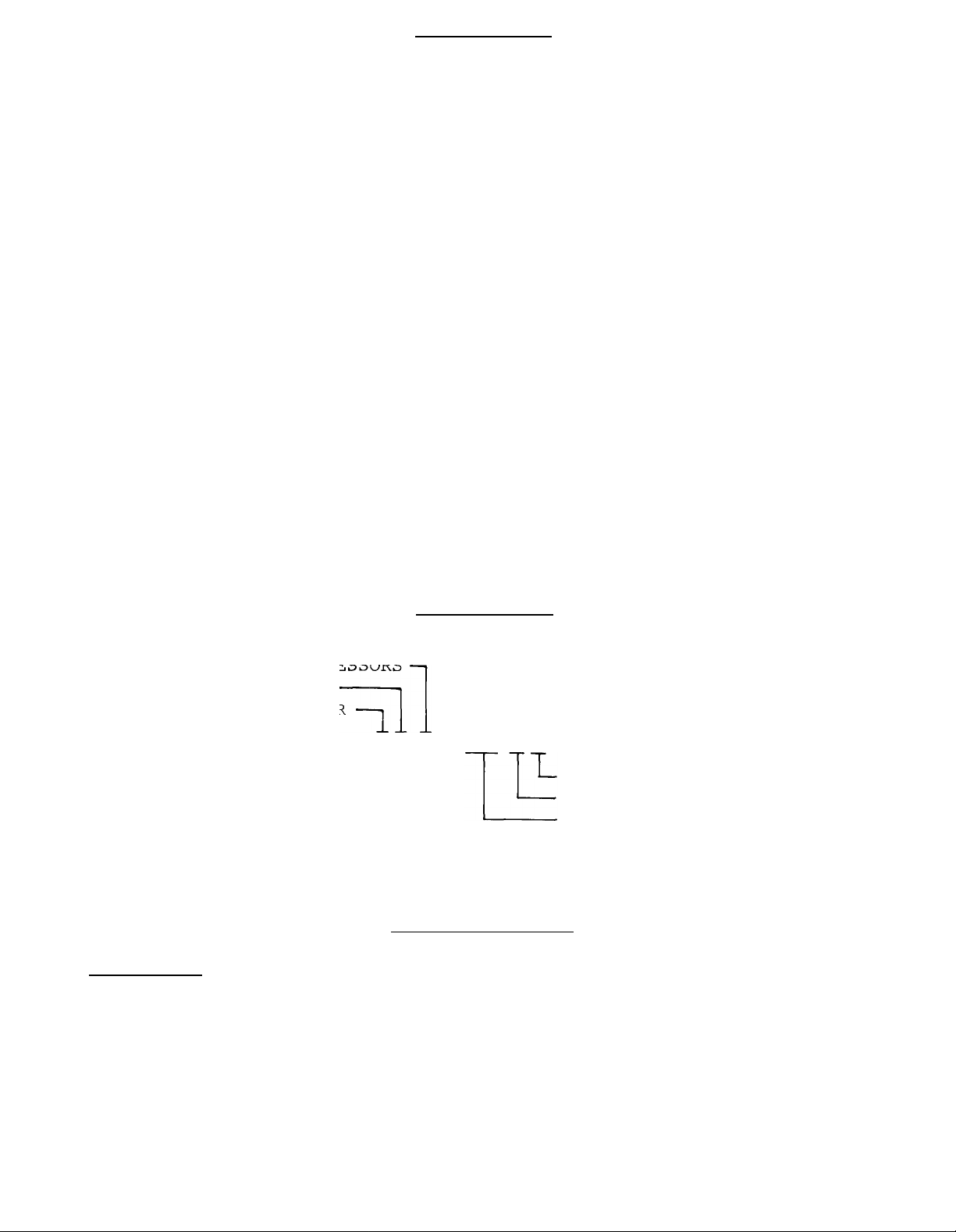
NOMENCLATURE
RECIPROCATING COMPRESSORS
LOW POWER CONSUMING
AIR COOLED CONDENSER
11
-It
ALR- 085AD
DUAL REFRIGERANT CIRCUITS
DESIGN VINTAGE
NOMINAL CAPACITY (TONS)
PRE-INSTALLATION
Inspection
When the equipment is received,
against the bill of lading to insure a complete shipment.
should be carefully inspected for damage upon arrival.
damage should be reported to the carrier and a claim should be filed.
The unit serial plate should be checked before unloading the unit to
be sure that it agrees with the power supply available.
all items should be carefully checked
All units
All shipping
Page 3
Page 4
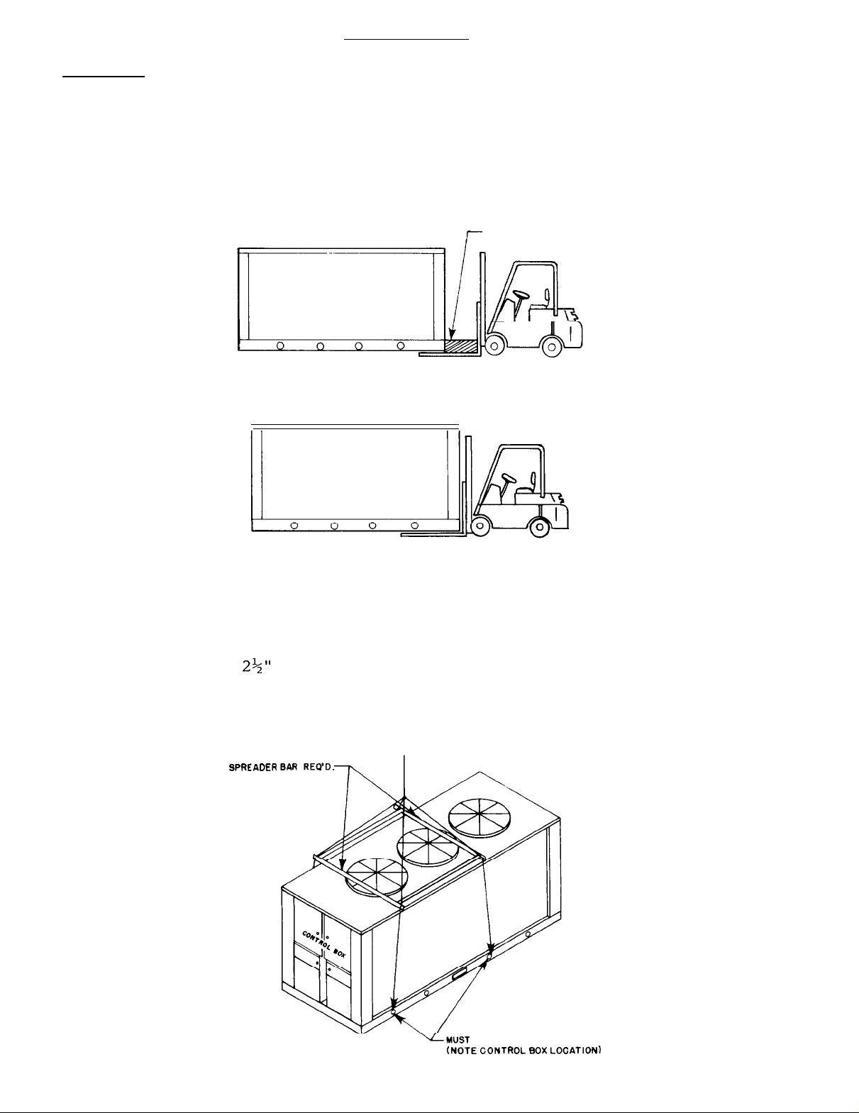
Handling
INSTALLATION
Care should betaken to avoid rough handling or shock due to
ping the unit.
Do not push or pull the unit from anything other
drop-
than the base,and block the pushing vehicle away from the unit to
prevent damageto the sheet metal cabinet.
FIGURE 1
SUGGESTED PUSHING ARRANGEMENT
7
GOOD PUSHING ARRANGEMENT
CABINET DAMAGE UNLIKELY
(See Figure 1).
BLOCKING
POOR PUSHING ARRANGEMENT
CABINET DAMAGE LIKELY
Never allow any part of the unit to fall during unloading or moving
as this may result in serious damage.
To lift the unit,
2%"
diameter lifting holes are
provided in the base
of the unit. Spreader bars and cables should bearranged to prevent
damage to the condenser coils or unit cabinet.
FIGURE 2
SPRE
SUGGESTED LIFTING ARRANGEMENT
:ADER
(See Figure 2).
Page 4
‘LMUST
(NOTE CONTROL
USE THESE RIGGING HOLES
Box
LOCATION)
Page 5

Location
Due to the vertical condenser design, it is recommended that certain
precautions be taken before installation to orient the unit so that
prevailing winds blow parallel to the unit length thus minimizinq
effects on condensing pressure.
the unit in this manner, a wind
If it is not practical to orient
deflecting fence should be
consi-
dered.
It is also necessary to provide
the unit for service access and
60 in.
(1
fan diameter) should be allowed on each side of the unit
for condenser air inlet and compressor removal on units 060
adequate clearance on all sides of
satisfactory performance.
At least
&
065.
If parallel units are installed side by side, 120 in. should be
allowed between units.
This will prevent excessive condensing
temperatures and enhance system performance and operating economy.
Clearance for service access should be at least 78 in. at the
control center end for compressor removal on units 075 thru 130
and sufficient at the end opposite the control center for evaporator tube replacement.
FIGURE 3
60” MINIMUM-CLEARANCE
These clearances are illustrated in Figure 3.
CLEARANCE AROUND UNIT
FOR AIR INLET
11
60” MINIMUM CLEARANCE
FOR AIR INLET AND COMPRESSOR
REMOVAL ON ALR-060,065
NOTE: Minimum vertical clearance above unit should be
4
h
10 feet
I I
Access for Servicing
Each end of the unit must be accessible after installation for peri-
odic service work.
Compressors,
filter driers,
and manual liquid
line shutoff valves are accessible from the control center end of the
unit through removable access panels on unit sizes 075 thru 130 and
hinged side access doors on unit sizes 060 and 065.
safety,
They are protected by a keylocked,
tains internal "dead front"
nel from high
operational controls.
located just below the main control center.
and starting controls are located in the unit control center.
weatherproof enclosure which con-
doors for protection of service person-
voltage starting controls while servicing low voltage
All resettable or adjustable controls are
There is one resettable
All operational,
control enclosure on each side of the unit and each encl.osure contains
controls for compressors on that side of the unit.
Capped connections
for field service gauges are also located inside these enclosures. In
addition,
each of these enclosures are removable to improve access to
compressors for field replacement.
Page 5
Page 6
The condenser fans, motors,
and drives are accessible through a walk-
in, keylocked access door on units ALR-075 thru 130 or a removable
access panel on units ALR-060 and
located at the end of the unit opposite the control center.
065.
The access door or panel is
Expan-
sion valves are accessible from the same access door on unit sizes
075 thru 130 and from side access doors at the control center end
on unit sizes 060 and 065.
An internal fan guard is located below the condenser fans and drives
on units 075 thru 130.
This guard must be removed to service the
fan drives but must always be re-installed when service work is com-
plete.
On unit sizes 060 and 065,
an interlock switch kills power
to condenser fans whenever the access panel is removed for service
work on fans or drives.
CAUTION:
Disconnect all power to the unit while
servicing condenser fan drives.
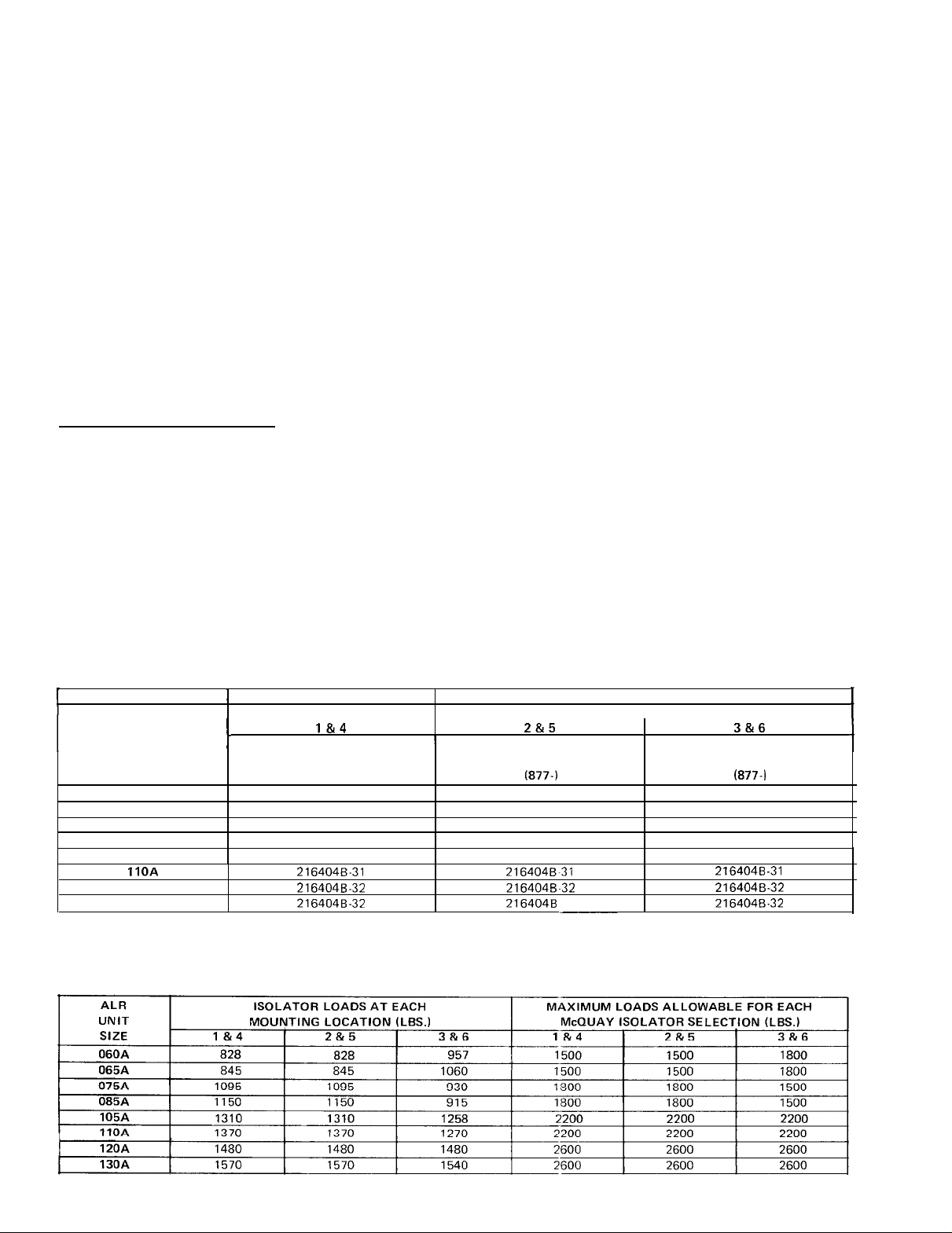
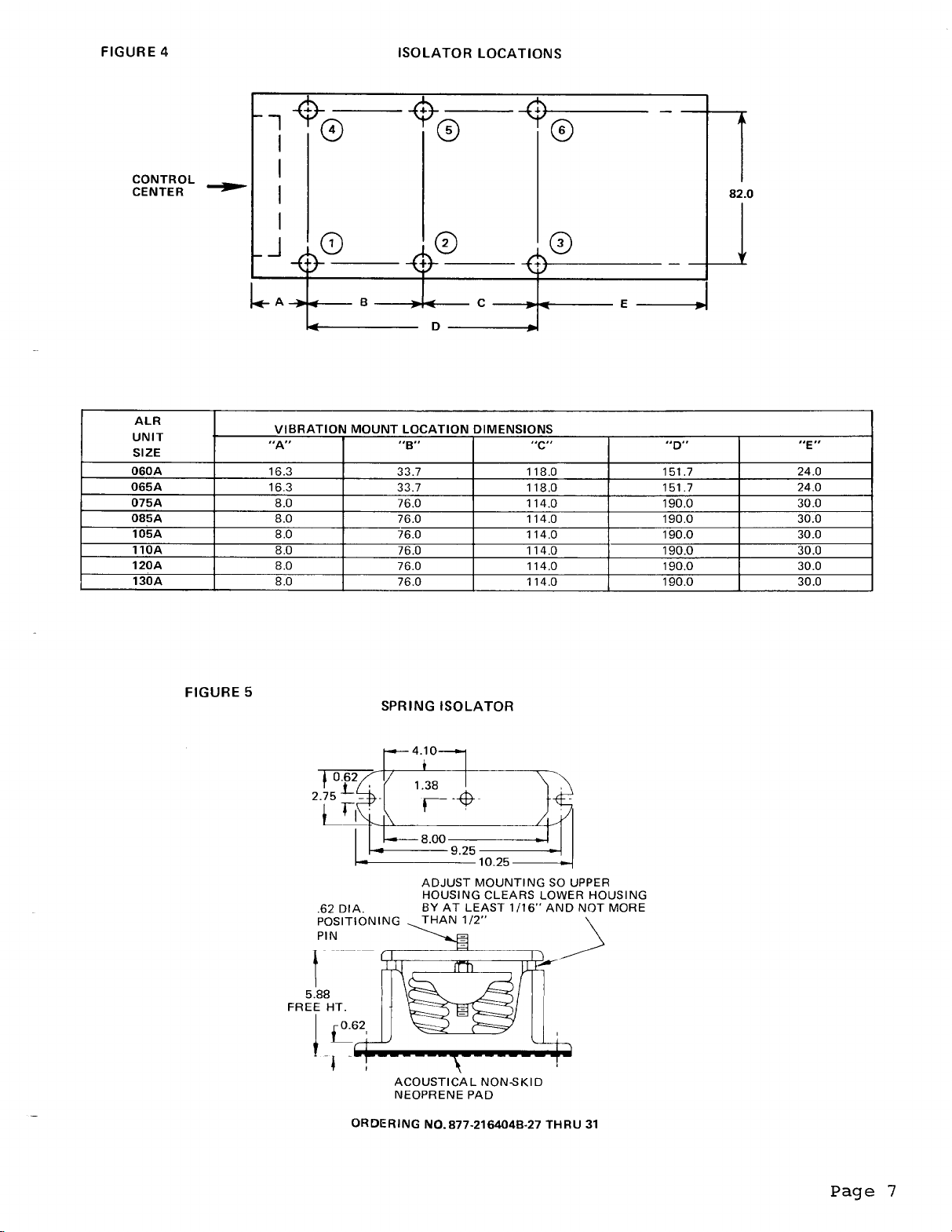
Vibration Isolators
Vibration isolators are recommended for all roof mounted installa-
tions or wherever vibration transmission is a consideration.
lists spring isolators for all ALR unit sizes.
tor locations in relation to the unit control center.
Figure 4 shows isola-
Figure 5 gives
Table 1
dimensions that are required to secure each McQuay isolator selection
to the mounting surface.
For applications which require a higher degree of isolation efficiency,
Table 2 shows the isolator loads at each location shown in Figure 4,
and the maximum loads for each McQuay selection.
TABLE 1
I
ALR LOCATIONS LOCATIONS
UNIT
SIZE
060A
065A
075A 2 164048-28
085A 2 16404B-28
105A
IIOA
120A
130A
I
l&4
t
ORDERING
NUMBER NUMBER
(877-j
216404B-27
216404B-27 216404B-27
2164048.31
216404B.31
216404B.32 216404B-32
216404B.32 216404B
VIBRATION ISOLATORS
SPRING ISOLATORS
Z&5
I
ORDERING
(877-j
216404B~27
216404B-28
216404B-28
216404B-31
2164048-31
32
__-
I
I
LOCATIONS
3&6
ORDERING
NUMBER
(877-i
216404B-28
216404B-28
216404B-27
216404B-27
216404B-31
216404B.31
216404B-32
216404B-32
I
1
_
TABLE 2
Page 6
ISOLATOR LOADS
Page 7
Page 8
WATER PIPING
Piping Practices
Due to the variety of piping practices, it is advisable to follow
the recommendations of local authorities.
They can supply the in-
staller with the proper building and safety codes required for a
safe and proper installation.
Basically,
the piping should be designed with a minimum number of
bends and changes in elevation to keep system cost down and perfor-
mance up.
1.
Vibration eliminators to reduce vibration and noise transmission
It should contain:
to the building.
Shutoff valves to isolate the unit from the piping system dur-
2.
ing unit servicing.
Manual or automatic air vent valves at the high points of the
3.
system.
4.
Some means of maintaining adequate system water pressure (e.g.;
expansion tank or regulating valve).
5.
Temperature and pressure indicators located at the unit to aid
in unit servicing.
6.
A strainer or some means of removing foreign matter from the
water before it enters the pump.
It should be placed far enough
upstream to prevent cavitation at the pump inlet (consult pump
manufacturer for recommendations).
The use of a strainer will
prolong pump life and thus keep system performance up.
Prior to insulating the piping and filling the system, a preliminary
leak check should be made.
Piping insulation should include a vapor barrier to prevent moisture
condensation and possible damage to the building structure.
It is
important to have the vapor barrier on the outside of the insulation
to prevent condensation within the insulation on the cold surface
of the pipe.
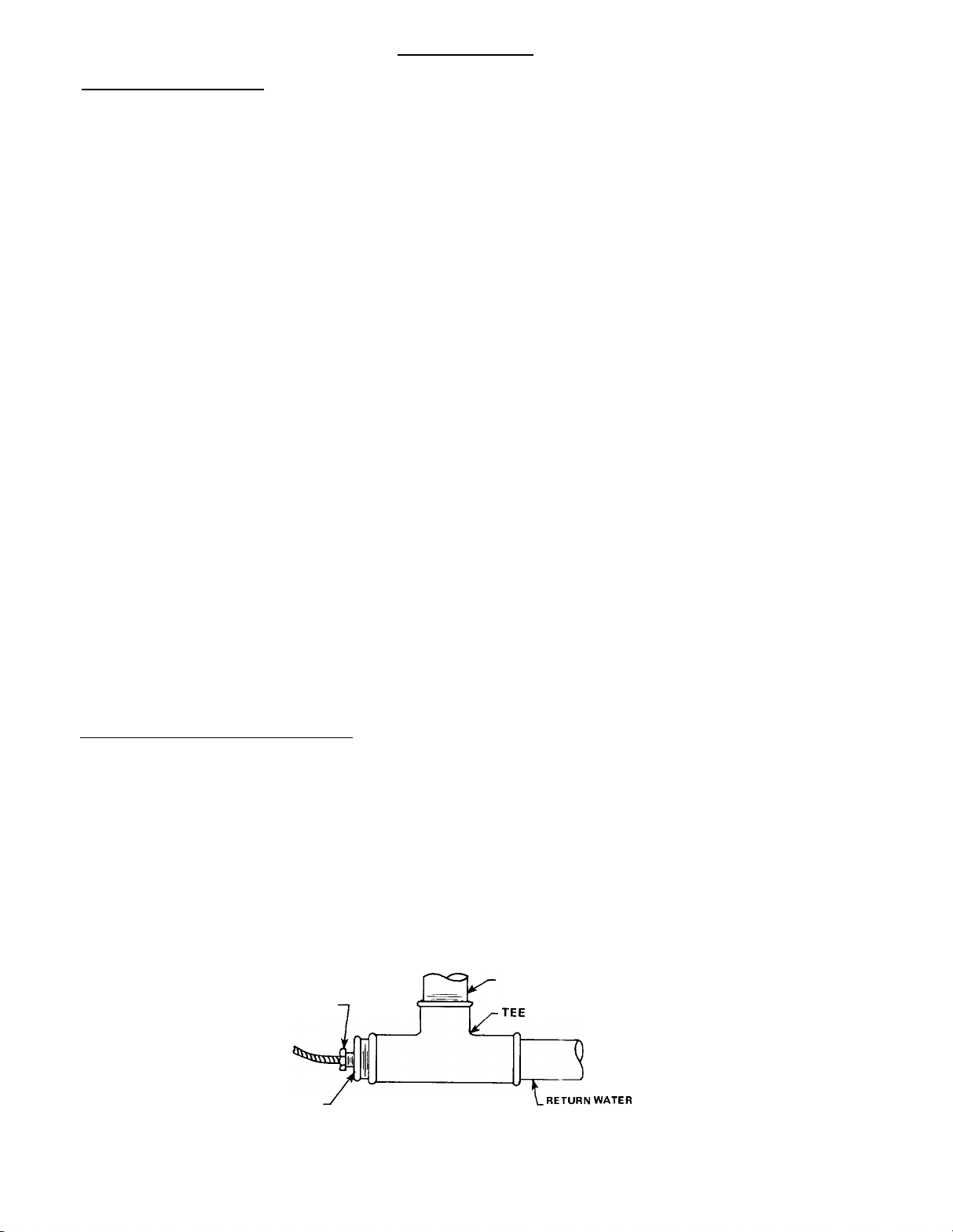
Chilled Water Thermostat
The chilled water thermostat is mounted inside the unit control center.
On models ALR-075A through
130A,
the thermostat sensor is fac-
tory mounted in the return water connection of the evaporator. On
models
water line as shown in Figure 6.
ALR-060A
and
065A,,
the sensor must be installed in the return
The thermostat sensor should be in-
sulated after installation.
FIGURE 6
THERMOSTAT
SENSOR
REDUCING
BUSHING
THERMOSTAT SENSOR INSTALLATION
RETURN WATER CONNECTION
OF EVAPORATOR
7
1
LRETURN WATER LINE
Page 8
Page 9

CAUTION:
Flow Switch
Thermostats have maximum operating temperature limits of:
ALR-060 and 065
140F on return water for standard ca-
pacity reduction.
125F on return water for optional capacity reduction.
ALR-075 throuqh 130
125F on return water for standard capacity reduction.
250F on return water for optional ca-
pacity reduction.
Temperatures exceeding these limits may damage the controls.
WATER FLOW SWITCH
A
ing water line to insure that there will be adequate water
cooling load to the evaporator before the unit can start.
safeguard against slugging the compressors on start up.
MUST
BE MOUNTED in either the entering
or
leav-
flow and
This will
It also
serves to shut down the unit in the event that water flow is interrupted to guard against evaporator freeze up.
A flow switch is available from McQuay under ordering number 860-
175033x-00.
size from
to close the switch and are listed in Table 3.
It is a "paddle"
1"
to 6" nominal.
type switch and adaptable to any pipe
Certain minimum flow rates are required
Installation
should be as shown in Figure 7.
TABLE
3
FLOW SWITCH MINIMUM FLOW RATES
NOMINAL
PIPE SIZE
(INCHES)
1
1
l/4
1
l/2
2
2112
3
4
5
6
MINIMUM REQUIRED
FLOW TO ACTIVATE
SWITCH
6.00
9.80
12.70
18.80
24.30
30.00
39.70
58.70
79.20
(GPM)
FIGURE 7
+ FLOW4
DIA.
-
5 PIPE
AFTER SWITCH
MINIMUM 5 PIPE DIA.-MINIMUM
FLOW DIRECTION
/
J’
MARKED ON SWITCH
1.00
NPT FLOW SWITCH
CONNECTION
BEFORE SWITCH
Electrical connections in the unit control center should be made at
terminals 11 and 12.
should be wired between these two terminals.
_
normally closed contacts on the switch that could be used for an in-
The normally open contacts of the flow switch
There is also a set of
dicator light or an alarm to indicate when a "no flow" condition
exists.
Page 9
Page 10
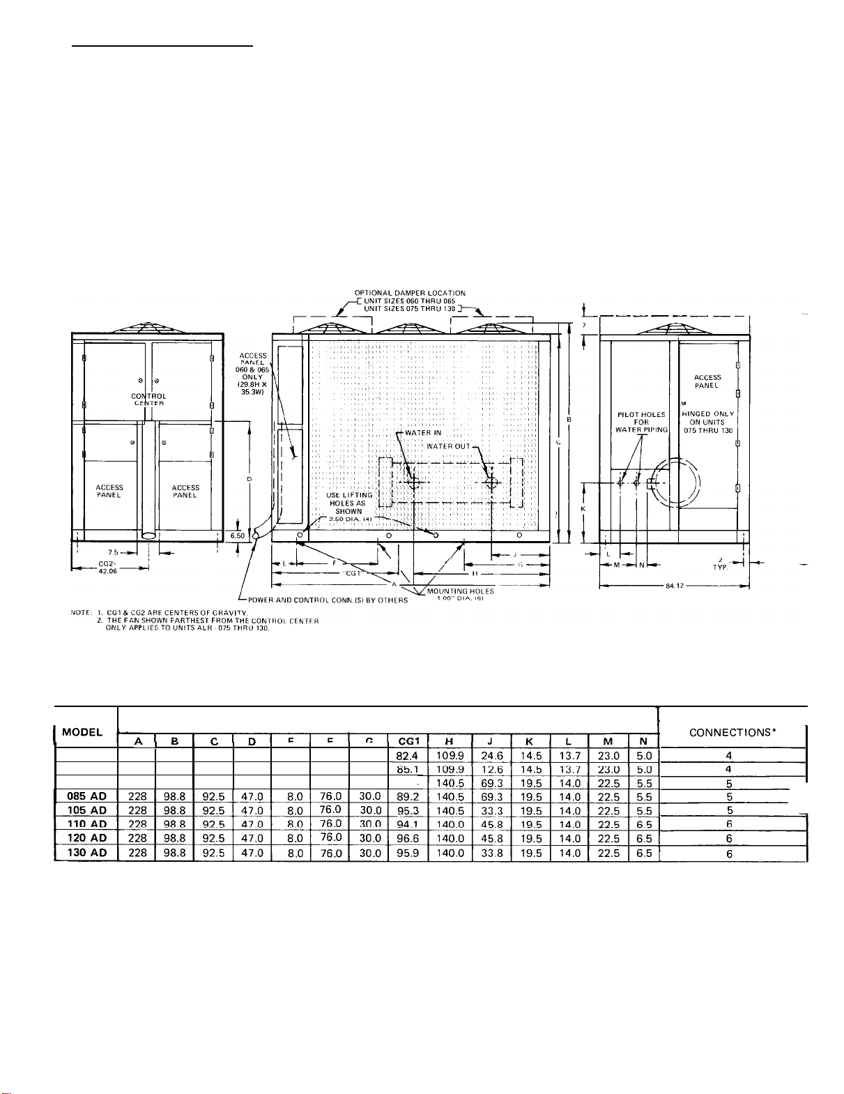
Piping Connections
Water piping connections at the unit vary in size and style depen-
ding on the baffle option ordered.
These connection variations are
shown in the table with Figure 8.
Piping through the unit cabinet can be through the end or bottom of
the unit as the application dictates.
hole centers for piping through the end of the unit.
Pilot holes locate
Figure 8 gives
the proper
the necessary dimensions for either piping method.
FIGURE 8
1
ALR
r\,
Y
Y
060AD 192 80.0 73.8 36.1 16.3 33.7 24.0
065AD 192 80.0 73.8 36.1 16.3 33.7 24.0
075AD 228 98.8 92.5 47.0 8.0 76.0 30.0 91.4
*COOLER CONNECTIONS
Y
-
Ail
connections
couplings by others.
DIMENSIONS (INCHES)
are NPS steel
Page 10
tib.1
pipe.
4
thru
6-inch
pipe
connections are
furnished
COOLER
with grooves for
I
victaulic
Page 11
Field Wirinq
FIELD WIRING
Wiring should be done in accordance with
all applicable codes and
ordinances.
Warranty
-Warranty is voided if wiring is not in accordance with specifica-
tions.
An
open fuse indicates a short, ground, or overload.
Before
replacing a fuse or restarting a compressor or fan motor, the trouble must be found and corrected.
Copper wire is required for all power lead terminations at the unit
while either aluminum or copper can be used for all other wiring.
All unit sizes are set up as standard for separate 115 volt power
supply circuits for the control circuit and cooler heater.
The con-
trol circuit only or both the control circuit and cooler heater can
be powered off of the main unit power supply if the optional control
circuit transformer is ordered.
have the unit
the main unit
out defeating
cooler heater on a separate disconnect switch from
power supply so that the unit may be shut down with-
the freeze protection provided by the cooler heater.
It may be desirable, however, to
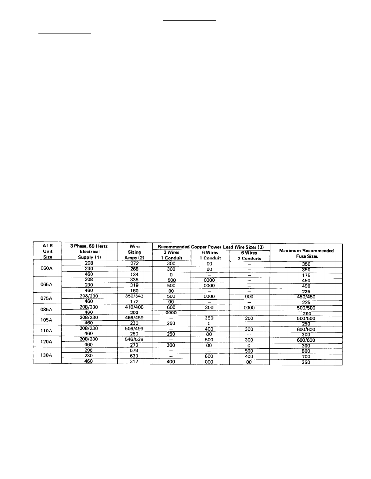
TABLE 4
Wire sizing ampacities and recommended power lead wire sizes
Notes: 1. Separate terminals provide for the field connection of a
separate
2. Wire sizing amps are equal to 125% of the Nameplate
Amps of the largest motor plus 100% of the Nameplate
Amps of all other loads in the circuit (the control circuit
is not included). To include the control circuit, add 10
amps to 208 or 230 volt units and 5 amps to 460 volt
units. Recommended power lead wire and maximum fuse
sizes are not affected.
3. Recommended power lead wire sizes for three conductors per conduit are based on 100% conductor
115/60/1
power supply to the control circuit.
ampacity at 86 F ambient for no more than 3 conductors
per conduit. Wire sizes for six conductors per conduit are
based on 80% of the above mentioned conductor
ampacity in accordance with NEC. Voltage drop has not
been included, therefore, it is recommended that power
leads be kept short. All terminal block connections must
be made with copper wire.
4.
The unit power terminal block has two lugs per phase.
Single or parallel conductors per phase may be used for
power hookup as listed under “Recommended Power
Lead Wire Size.”
The cooler heater cable current draw is 3.5 amps.
5.
Page 11
Page 12

Page 13

A standard feature on all ALR units is
COPSTM(Controlled
Override of
Pump Shutdown),a system for interlocking the field supplied chilled
water pump into the chiller control system.
A relay (R-19) is wired
into the unit control circuit so that a time clock and/or ambient
thermostat can be connected to a pair of terminals (6 and 11) inside the unit control center.
starter.
Once the pump starts,
The time clock can energize a pump
the flow switch and/or pump inter-
lock will close and energize that part of the control circuit that
will allow the unit to start.
This feature makes it possible to start the chilled water pump and
the chiller simultaneously only when cooling is required.
For re-
cycling pumpdown without a demand for cooling, a pair of relays
(energized by low pressure controls) are also wired into this cir-
cuit to start the pump,
close the flow switch and pump down the
unit.
NOTE:
If a time clock,
ambient thermostat and/or re-
mote on-off switch are not used, terminals 6
and 11 must be jumpered together before the
unit will start.
Figure 9 shows typical field wiring that is required for unit installation.
FIGURE 9
TYPICAL FIELD WIRING DIAGRAM
Standard is separate power supply circuits for controls
and cooler heater. These circuits may be combined by
installing jumpers from terminals 1
NOTE C:
Pump starter, contacts of R9,
terminals 7 & 8 are limited to 250 volts maximum.
CUSTOMER CONNECTION
FIELD WIRING
FACTORY WIRING
BLACK WIRING (LINE)
WHITE WIRING (NEUTRAL)
flow switch and/or starter interlock.
-
9 & 10 - 20.
R10,
and
R19
between
START - UP AND SHUT DOWN
Pre Start-Up
1.
With all electric disconnects open,
check all screw or lug type
electrical connections to be sure they are tight for good electrical contact.
fore shipment,
Although all factory connections are tight be-
some loosening may have resulted from shipping
vibration,
2.
Inspect all water piping for flow direction and correct connections at the evaporator.
Page 13
Page 14
3.
4.
5.
6.
7.
8.
9.
10.
Open all water flow valves and start the chilled water pump.
Check all piping for leaks and vent the air from the evaporator
as well as from the system piping.
system piping to obtain clean,
orator circuit.
Check to see that the thermostat water temperature sensor is installed in the return water line (return to chiller).
075A through
ALR-060A
tion,
and the sensor should be secured in the well with the retaining
clip provided. On ALR-075A through 130A units with optional cap-
acity reduction,the sensor is installed directly into the return
water line i.e.;
Check the compressor oil level. Prior to start-up, the oil level should cover at least
Remove the (8) compressor shipping blocks that are attached to the
compressor rails and the base of the unit.
not have shipping blocks.
Check the voltage of the unit power supply and see that it is
within the
balance must be with _+ 2%.
Check the unit power supply wiring for adequate ampacity and a
minimum insulation temperature rating of 75C.
Verify that all mechanical and electrical inspections have been
completed per local codes.
See that all auxiliary control equipment is operative and that
an adequate cooling load is available forinitial start up.
and 065A units with standard or optional capacity reduc-
the sensor well should be full of heat conducting
13OA
+
10%
units with standard capacity reduction, or
no well or heat conducting compound is required.
l/2
tolerance that is allowed.
non-corrosive water in the evap-
of the oil sight glass.
Flush the evaporator and
On
ALR-
compound
The ALR 060 and 065 do
Phase voltage un-
_
Start-Up
1.
Open the compressor suction and discharge
back seated.
2.
Open the manual liquid line shutoff valve at the outlet of the
subcooler.
Check to see that pumpdown switches
3.
pumpdown"position and the control stop switch
"on
"
position.
Adjust the dial on temperature controller
4.
chilled water temperature.
Throw the main power and control circuit disconnects to the "on"
5.
position.
CAUTION:
6.
Allow the crankcase heaters to operate for at least 8 hours prior
to start-up.
Start the auxiliary equipment for the installation by turning
7.
on the time clock,
if the unit and chilled water pump are electrically interlocked
by using the COPS
8.
Start the system by moving pumpdown switches
"auto.
9.
After system performance has stabilized, it
"Compressorized Equipment Warranty Form" (form no. 206036A) be
completed to obtain full warranty benefits.
with the unit and after completion should be returned to McQuay's
Service Department through your sales representative.
pumpdown" position.
Always replace valve seal caps.
(PSl &
Most relays and terminals in the unit
control center are hot with
control circuit
ambient thermostat and/or remote on/off switch
method discussed in "Field Wiring".
disconnect
shutoff valves until
PS2) are in the
(Sl)
is in the
TCl
to the desired
Sl
and the
on.
(PSl &
is
necessary that the
This form is shipped
PS2) to the
"man.
Page 14
Page 15

Temporary Shut-Down
Move pumpdown switches
After
pump.
It is important that the compressors pump down before the water flow
to the unit is interrupted to avoid freeze up in the evaporator.
Start-Up After Temporary Shut-Down
1.
2.
3.
Extended Shut-Down
1.
2.
3.
4.
5.
6.
7.
the compressors have pumped down, turn off the chilled water
NOTE:
Start the chilled water pump.
With control stop switch
down switches
Observe the unit operation for a short time to be sure that the
compressors do not cut out on low oil pressure.
Close the manual liquid line shutoff valves.
After the compressors have pumped down, turn off the chilled
water pump.
Turn off all power to the unit and to the chilled water pump.
Move the control stop switch
Close the compressor suction and discharge valves.
Tag all opened disconnect switches to warn against start up be-
fore opening the compressor suction and discharge valves.
Drain all water from the unit evaporator and chilled water pip-
ing if the unit is to be shut down during winter.
With the unit left in this condition, it is
capable of recycling pumpdown operation. To
defeat this mode of operation, simply move
control stop switch
(PSl &
(PSl
& PS2) to the "man. pumpdown" position.
(Sl)
to the "off" position.
(Sl)
in the
PS2) to the "auto. pumpdown" position.
(Sl)
to the "off" position.
"on"
position, move pump-
Start-Up After Extended Shut-Down
1.
Inspect all auxiliary equipment to see that it is in satisfac-
tory operating condition.
2.
Remove all debris that has collected on the surface of the condenser coils.
3.
Open the compressor suction and discharge valves.
4.
Open the manual liquid line shut off valves.
c
J.
Check to see that pumpdown switches
ual pumpdown position.
6.
Turn on the electric power to the unit and other parts of the
system.
7.
Allow the crankcase heaters to operate for at least 8 hours
prior to start-up.
8.
Start the chilled water pump and purge the water piping as well
as the evaporator in the unit.
9.
Check to see that the control stop switch
tion.
CAUTION:
Most relays and terminals in the unit
control center are hot with
control circuit disconnect on.
(PSl
and PS2) are in the man-
(S1)is
Sl
in the
and the
"on"
posi-
Page 15
Page 16

10.
Start the unit by moving
pumpdown
switches
(PSl
& PS2) to the
"auto.pumpdown" position.
11.
After running the unit for a short time check the oil level in
each compressor crankcase and check for flashing in the refrigerant sight glass (see "Maintenance" on Page 47).
ELECTRICAL
Control Center
All electrical controls are enclosed in a weatherproof control cen-
ter with keylocked, hinged access doors.
posed of three separate enclosures.
The upper enclosure is the
largest and contains all of the 208, 230,
fan motor starting controls.
Also included in this enclosure but
partitioned separately are the exposed terminal type
ational controls.
A "dead front"
cover over the high voltage sec-
The control center is com-
or 460 volt compressor and
-
115 volt oper-
tion protects service personnel from high voltage starting controls
while servicing low voltage operational controls.
Below the upper enclosure are two smaller,
contain 115 volt adjustable or resettable controls.
separate enclosures that
There is one of
these enclosures on each side of the unit, and each contains controls
for the compressors on that side.
Power supply conduits are intended to come into the bottom of the
upper enclosure and between the two lower enclosures.
mended that the unit disconnect switch be mounted away
but
Figure 10 recommends unit mounting arrangements if the disconnect
it is recomfrom the unit
must be unit mounted.
Page 16
Page 17

Page 18

ELECTRICAL LEGEND
-A--
---_
--CL
200
\\
AB
F1
F2
Ft31,2,3.4
FE5
FB11,12,13
FS1.2
HP1.2
HP
HTRl,
HTR5
JB
LPI,2
LP
Ml thru 8
Ml
1,12,13
MPI
thru 4
OP1,2,3,4
OP
PBl
PC1 and PC2
TC5 and TC6
PS1.2
R3.4
R5,6,7.8
R9.10
R13.14
R15, 16
R17.18
RI9
Sl
S2,3,4
Tl
TD1,2,3,4
TD5.6,7.8
TD9,lO
TD11,12,13
NB1.2
TB6,7
TB5.8.9
TCl
SC1
T2
T4
TC2
thru 4
FIELD WIRING AND NUMBERED TERMINAL
OPTIONAL WIRING
FACTORY WIRING AND NUMBERED TERMINAL
WIRE NUMBER
OPTIONAL CONTROLS
CONNECTER
ALARM BELL
CONTROL CIRCUIT FUSE
EVAPORATOR HEATER FUSE
FUSE BLOCKS (COMP.
CONTROL CIRCUIT TRANSFORMER FUSE BLOCK - OPTIONAL
FUSE BLOCKS (COND. FAN
FREEZE CONTROLS (REF. CIRCUIT
HIGH PRESSURE CONTROLS (REF. CIRCUIT
HIGH PRESSURE GAUGE -OPTIONAL
CRANKCASE HEATERS (COMP.
EVAPORATOR HEATER
JUNCTION BOX (FOR ALARM BELL)
LOW PRESSURE CONTROLS (REF. CIRCUIT
LOW PRESSURE GAUGE -OPTIONAL
CONTACTORS (COMP.
CONTACTORS (COND. FAN
MOTOR PROTECTORS (COMP.
OIL PRESSURE CONTROLS (COMP.
01
L PRESSURE GAUGE - OPTIONAL
MAIN POWER TERMINAL BLOCK
FANTROL PRESSURE CONTROLS
FANTROL TEMPERATURE CONTROLS
PUMPDOWN
STARTER RELAYS (COMP.
SAFETY RELAYS (COMP.
LOW PRESSURE RELAYS (REF. CIRCUIT
LOW AMBIENT START RELAYS (REF. CIRCUIT
COMPRESSOR LOCKOUT RELAYS
CONDENSER FAN RELAY
PUMP STARTER RELAY
CONTROL STOP SWITCH
LEAD-LAG SWITCHES
CONTROL CIRCUIT TRANSFORMER
PART WINDING TIME DELAYS (COMP.
COMP. LOCKOUT TIME DELAYS (COMP. 1,2,3,4)
LOW AMBIENT START TIME DELAYS (CIRCUIT 1,2)
COMP. SEQUENCING TIME DELAYS (STAGES
TERMINAL BLOCKS (NEUTRAL-FACTORY WIRING)
TERMINAL BLOCKS (HOT-FACTORY WIRING)
TERMINAL BLOCKS (FIELD WIRING)
WATER TEMP. CONTROL THERMOSTAT
OPTIONAL WATER TEMP. CONTROL THERMOSTAT SIGNAL CENTER
OPTIONAL WATER TEMP. CONTROL THERMOSTAT TRANSFORMER
ALARM BELL TRANSFORMER
COOLER HEATER THERMOSTAT
SWITCHES (REF. CIRCUIT 1.2)
-
SEE WI RING DIAGRAMS
1,2,3,4)
11,12,13)
1,2,3,4)
11,12,13)
3,4)
1,2,3,4)
1,2)
1,2,3,4)
-
OPTIONAL
1,2,3,4)
1,2,3,4)
-
OPTIONAL
-
OPTIONAL
-
OPTIONAL
1,2)
1,2)
1,2,3,4)
1,2)
1,2)
-OPTIONAL
-OPTIONAL
-
OPTIONAL
-
OPTIONAL
2,3,4)
Sequence of Operation
The following sequence of operation is typical for ALR Seasonpak air
cooled water chiller operation.
unit,
referred
pressors
but where components that apply to the fourth compressor are
the equivalent components for the third and second
to,
of a 3 or 2 compressor unit are
It is written for a 4 compressor
indicated in parentheses.
Page 18
com-
Page 19

With the control circuit power on,
and manual pumpdown switches
115 volt power is applied through control circuit fuse
compressor crankcase heaters
also to the contacts of low pressure switches
PSl
HTRl
control stop switch
and PS2 closed ("Auto" position),
through HTR4,
(HTR3,
LPl
and LP2.
~1
closed,
Fl
to the
HTR2,) and
When the remote time clock or manual shutdown switch turns "on",
pump starter relay
the chilled water pump.
thermostatic circuit also close. With the flow switch closed, if
freeze controls FSl and 2,
pressor motor protectors MPl through MP4 (MP3,
alarm condition,safety relays
applying power to the water temperature controller
operate automatically in response to
On a call for cooling,
gizes liquid line solenoid valve
refrigerant to flow into the evaporator.
builds up,
relay
compressor number 1.
denser fan relay R17,
condenser fan motor contactors
units,
If additional stages of cooling are required, temperature control
thermostat
delay relay TDll has sequenced closed,
sequence in refrigerant circuit number 2.
R9
low pressure control
which closes to energize compressor contactor Ml, starting
or
Mll,
TCl
energizes liquid line solenoid valve SV2 after time
R19
is energized,
Relay
the temperature control thermostat
Closing relay
closing its contacts and providing power to
&
12 on 2 compressor units.
R19,
high pressure controls HP1 and 2 and com-
R5
LPl
Mll,
closing contacts 1 and 3 to start
contacts 4,
through R8 (R7,
TCl.
SVl,
opening the valve and allowing
closes,
R9
contacts also energizes con-
12 & 13 on 3 & 4 compressor
6, 7 and 9 in the
MP2)
do not sense an
R6)
are energized
TCl.
As refrigerant pressure
energizing low pressure
to initiate the same starting
The unit will
TCl
ener-
COPSTM
On 3 and 4 compressor units,
the third and fourth stages of temperature control thermostat
energize the third and fourth compressors after time delay relays TD
TD13
12 and
Pumpdown Cycle
As temperature control thermostat
contacts,
valve to close.
gerant from the evaporator to the condenser,
LPl
opens,
Should a closed solenoid valve allow refrigerant to leak to the low
side of the refrigerant circuit during unit "off"
in pressure will cause the low pressure control to close, energizing
the low pressure relay and starting the compressor for pumpdown.
have sequenced closed.
de-energizing liquid line solenoid valve
When the compressor has pumped most of the refri-
shutting down the compressor and condenser fan motors.
if additional cooling is still required
TCl
TCl
is satisfied, it opens its
SVl,
causing the
the low pressure control
time,
the buildup
Page 19
Page 20

Page 21

Page 22

Page 23

Page 24

Page 25

Page 26

Page 27

Page 28

Page 29

Page 30

Page 31

Page 32

Page 33

Page 34

Page 35

Page 36

Page 37

Page 38

Page 39

Page 40

Page 41

High Pressure Control
The high pressure control is a single pole pressure activated switch
that opens on a pressure rise to de-energize the entire control circuit except for compressor crankcase heaters and the cooler heater.
It senses condenser pressure and is factory set to open at 380 PSIG
and can be manually reset closed at 315 PSIG.
To check the control,
either block off condenser surface or start the unit with fuses in
only one fan fuse block
(FB11)
control by watching condenser pressure rise.
and observe the cut-out point of the
The highest point
reached before cut-out is the cut-out setting of the control.
CAUTION:
Although there is an additional pressure relief device in
the system set at 425 PSIG,it is highly recommended that the "control
Stop"
switch
(S1)
be close at hand in case the high pressure control
should malfunction.
Low Pressure Control
The low pressure control is a single pole
on a pressure rise.
It senses evaporator
set to close at 60 PSIG and automatically
the control (unit must be running),
move the pumpdown
and PS2) to the "man. pumpdown" position.
down
condenser pressure will rise and evaporator pressure will drop.
pressure switch that closes
pressure and is factory
open at 35 PSIG.
To check
switch(es) (PSl
As the compressor pumps
The lowest evaporator pressure reached before cut-out is the cut-out
setting of the control.
to the "auto. pumpdown" position,
By moving the pumpdown
evaporator pressure will rise.
switch(es) (PSl &
PS2)
The
highest evaporator pressure reached before compressor re-start is the
cut in setting of the control.
Freeze Control
LINE (SEE NOTE
LINE (SEE NOTE 2)
NOTES: 1. Hot whenever unit compressor(s) is running.
1)
CONTACT
2. Hot whenever control circuit flow
stop switch
3. Provides power to energize compressor contactors
through low pressure relay
T2
(S1)
are closed.
L M
YI
(R9
or
BIMETALLIC CONTACT
switch
and control
R10).
NEUTRAL
HEATER ELEMENT
LINE (SEE NOTE 3)
The freeze control is very similar to the oil pressure control in
operation except that it senses evaporator pressure only rather than
a pressure differential.
It contains a pressure actuated contact
that upon a fall in evaporator pressure energizes a heater element
that in turn opens a normally closed bimetallic contact.
bimetallic contact opens,
it de-energizes the entire control circuit
except for the compressor crankcase heaters and cooler heater.
When the
The
control is factory set to close at 52 PSIG and open at 54 to 57 PSIG.
It takes approximately 60 seconds to warm the heater element enough
to open the bimetallic contact.
This time delay period prevents
nuisance cutouts due to a momentary drop in suction pressure, but
since the control senses pressure rather than temperature, it still
provides quicker response for protection than a temperature sensing
control.
Page 41
Page 42

To check the control,
be connected across terminals of the pressure activated contact.
the unit running,
terminals.
(PSl
and PS2) to the "manual pumpdown" position. Evaporator pressure
will begin to drop.
vated contacts of the control will have closed.
pressure at which this happens.
down before the 60 second delay period,
not open before the unit shuts down.
tion may be checked after the pumpdown cycle is complete by connecting
a
jumper
control.
that evaporator pressure is sufficiently low.
the bimetallic contacts of the control should open.
Should the control(s) cause the unit to shut down during normal operation,
bimetallic contacts of the control will have cooled enough to allow
the control to be manually reset.
ty control,
prolong the time required before reset.
from terminal 1 in the control center to terminal T2 of the
Observing evaporator pressure,
This will energize the heater element of the control provided
a period of about 2 minutes will be required before the
repeated successive operations of the freeze control will
the system must be operating.
there should be a 115 volt potential across these
move the pumpdown
When the voltmeter goes to zero, the pressure acti-
Because the unit will have pumped
bimetallic contacts L
This part of the control opera-
Within about
Similar to the oil pressure safe-
A voltmeter should
switch(es)
Note the evaporator
&
M will
60
seconds,
With
Fantrol
Fantrol is a system for progressively turning on or off condenser
fans when they are no longer required.
denser capacity (typically in low outdoor ambient temperatures) and
is accomplished by a combination of pressure and temperature actu-
ated controls.
when the first compressor in the unit starts.
12) is controlled by a pair of parallel wired pressure switches,
one of which senses condenser pressure in refrigerant circuit No.1
and one which senses pressure in circuit
13-3 fan units only) is controlled by a pair of parallel wired tem-
perature switches,
ture for refrigerant circuit No.1 and one for circuit
and temperature control set points are indicated below.
-
Head Pressure Control
The first fan (No.
one of which senses condenser air inlet tempera-
This is done to reduce con-
11) is started by its contactor
The second fan (No.
No.2.
The third fan (No.
No.2.
-1
* No.
fan 13 on 060 and 065 unit.
To check the cut-in points of the controls, the unit must initially
be off.
cedures outlined in this bulletin,
to the "auto. pumpdown" position.
rise and the compressor(s) should start with fan No. 11 starting
immediately.
pressure as it rises.
mately 270 PSIG,
On 3 fan units, fan No.
the ambient air at the condenser inlet reaches 80F.
Page 42
With the unit prepared for start up according to the pro-
move pumpdown switches
Evaporator pressure will begin to
After the compressor(s) starts, observe condenser
When the condenser pressure reaches approxi-
contactor Ml2 should pull in to start fan No. 12.
13 should start via contactor Ml3 whenever
Pressure
(PSl &
PS2)
Page 43

It may be difficult to check the cut-out point of fan No. 13 (on 3
fan units) at the instant it happens,
the ambient air at the condenser inlet is below 70F.
cut-out point of fan No. 12,
unit must be
available or the fan operation and condenser pressure(s)
some means of reducing the load on the
must be observed as the load drops off naturally.
but it should be off whenever
To check the
When the conden-
ser pressure drops to approximately 170 PSIG, contactor Ml2 should
drop out to turn off fan No. 12.
Dampertrol
-
Optional Head Pressure Control
t
0
0
0
DAMPERTROL IN OPEN POSITION
t
-
DAMPER SECTION
UNIT CONDENSER
r
DAMPER SECTION
CONDENSER
DAMPERTROL IN BYPASS POSITION
Dampertrol is also a system for reducing condenser capacity when it
is not required.
It consists of an assembly of damper blades, link-
ages and blade operators installed over the first fan turned on by
Fantrol (Fan No.
11) and arranged to operated as shown above.
The
blade operators sense condenser pressure and extend or contract in
response to that pressure to open or close the damper blades as re-
quired to maintain adequate condenser pressure.
factory set to begin opening the damper blades at 170
The operators are
_+
5 PSIG and
to be fully open at 250 _+ 10 PSIG.
To check the damper blade operator pressure settings, the unit should
be started with the fuses removed from fans 11 and 13 (on 3 fan units
only).
should be completely closed.
At condenser pressures below 170 2 5 PSIG, the damper blades
As pressure rises above 170
2
5 PSIG,
the damper blades should begin opening and be fully open at 250 +
10 PSIG, leaving the fuses in on fan 12 will prevent head pressure
from becoming excessive since this fan will start after the fully
open setting of the damper operators has been observed.
Page 43
Page 44

Part Windinq Start
LINE
-
Optional
PART WINDING
;;;I
IS
NOTE: Line
only hot when the unit thermostat calls for compressor to run
COMPRESSOR CONTACTOR
(2nd
MOTOR WINDING)
Part winding start is available on all voltage units and consists of
a solid state time delay wired in series with the contactor that ener-
gizes the 2nd winding of each compressor motor.
limit current in-rush to the compressors upon start up.
Its purpose is to
As each com-
pressor starts,the contactor for the first motor winding is energized
instantly while that for the second motor winding is delayed for 1
second.
Control checkout is best accomplished by observation as each contactor is pulled in to see that the 1 second delay occurs before the
second contactor pulls in.
-
Low Ambient Start
Optional
NOTE :
Line is only hot when the unit thermostat calls for compressor to run
Low ambient start is available on all units as an option with Fantrol
and included automatically with optional Dampertrol or Seasontrol.
It consists of a solid state normally closed time delay wired in
series with a relay.
These are both wired in parallel to the liquid
line solenoid valve so that when the solenoid valve is energized by
the unit thermostat,
through the time delay.
the low ambient start relay is also energized
The relay has contacts that essentially
short circuit the low pressure control and allow the compressor to
start with the low pressure control open.
3/4
After about 2
the relay.
If the system has not built up enough evaporator pressure
to close the low pressure control,
minutes,
the time delay will open and de-energize
the compressor will stop.
The
time delay can be reset to its original normally closed position by
moving the pumpdown
position.
Moving the pumpdown switch back to the "auto. pumpdown"
switch(es) (PSl
or PS2) to the "man. pumpdown"
position will again energize the relay for another attempt at start
up.
If the system has built up enough evaporator pressure, the com-
pressor will continue to run.
Page 44
Page 45

To check the control,
wire(s) (No.113
&
LP2) from terminal 4 in the unit control center.
SC
turn off all power to the unit and remove the
213) leading to the low pressure control(s)
Remove the com-
(LPl
pressor fuses and jumper across terminals L & M of the freeze con-
trol(s) and oil pressure safety control(s).
Energize the control
circuit by turning on the control circuit disconnect or main power
disconnect (depending on the installation) and the control stop
switch
After about 2
Sl.
The compressor contactors should pull in instantly.
3/4
minutes they should drop out again.
Compressor Lockout - Optional
LOW PRESSURE
MI AUX.
NOTE)
NOTE:
Hot whenever freeze control and high pressure con
trol permit safe
I
t
I’ ‘2
TO UNIT THERMOSTAT
operation
RI5
I I
II 13
COMI?
LOCKOUT
TIME DELAY
COMPRESSOR
NEUTRALS
Compressor lockout consists of a solid state time delay wired in
series with the compressor contactor(
rapid compressor cycling when cooJ_ing demands are erratic.
Its purpose is to prevent
The circuit illustrated above is for the lead compressor in each refrigerant circuit. The circuit for the second compressor(s) performs the
same function but is wired differently (see unit wiring diagram).
When the unit thermostat no longer calls for cooling and the com-
pressor contactor have opened,
the lockout time delay breaks open
the circuit preventing compressor re-start.
The circuit remains open for a period of 5 minutes so that if the
unit thermostat should call for cooling before the delay period has
expired,
the compressor will not re-start.
After 5 minutes, the
time delay will close its contacts to complete the circuit and be
ready for start up.
The time delay opens its contacts whenever power to terminal 4 is interrupted and resets closed automatically after the time delay period.
To check the control,the compressor(s) must be running initially.
(PSl
Move the
tion.
pumpdown switch
Immediately after the compressor(s) have stopped running,
move the pumpdown switch back to the "auto. pumpdown" position.
lead compressor should not re-start for 5 minutes.
pressor in the
onds after the
high enough to
refrigerant circuit should start approximately 20
lead compressor,
require it.
or PS2) to the "man. pumpdown" posi-
The
The second com-
sec-
provided that the cooling load is
Each refrigerant circuit can be checked
the same way.
Page 45
Page 46

Alarm Bell - Optional
The 24 volt alarm bell is mounted inside the control center but not
wired to the control circuit.
It is expected that in most cases,
the customer will want to relocate the bell where it will be more
easily heard in the event of a safety failure.
There are leads for
connection of the bell inside a junction box which is located in the
unit control center.
All that is necessary is that the bell be
mounted in a preferred location and wired to the leads in the junction box.
The bell is wired into the control circuit so that it will sound
whenever there is a failure due to low oil pressure, motor overload,
an evaporator freeze condition,
or excessive condenser pressure.
Hot Gas Bypass
HOT GAS BYPASS PIPING DIAGRAM
Solenoid Valve
Bypass Valve
-
Optional
External Equalizer
Connection to Suction
Side of Evapoator
Expansion Valve
Remote Bulb
HOT GAS BYPASS ADJUSTMENT RANGE
REMOTE BULB ADJUSTMENT RANGE
80
30 40
50
TEMP
(OF) AT BULB
60
70
LOCATION
90
100
110
Hot gas bypass is a system for maintaining evaporator pressure at or
above a minimum value.
The purpose for doing this is to keep the
velocity of the refrigerant as it passes through the evaporator high
enough for proper oil return to the compressor when cooling load con-
ditions are light.
The system consists of a solenoid valve piped in series with a pressure regulating valve as shown above.
The solenoid valve is factory
wired to open whenever the unit thermostat calls for the first stage
of cooling.
opening at 58 PSIG (32 F for R-22)
a 80 F.
ambient temperature.
The pressure regulating valve is factory set to begin
when the air charged bulb is in
Since the bulb is factory mounted on
the suction line and suction line temperatures are usually in the
50F. to 60F range,
the chart above indicates that for ALR chillers,
the valve is factory set to begin opening at 54 to 56 PSIG.
setting can be changed as indicated above by changing the pressure
of the air charge in the adjustable bulb.
setting,
clockwise.
remove the cap on the bulb and turn the adjustment screw
To lower the setting,
turn the screw counter-clockwise.
To raise the pressure
Do not force the adjustment beyond the range it is designed for as
this will damage the adjustment assembly.
Page 46
This
Page 47

The regulating valve opening point can be determined by slowly reducing the system load (or increasing the required chilled water temperature setting indicated on the unit thermostat), while observing
the suction pressure.
frigerant line on the evaporator side of the valve will begin to
feel warm to the touch.
CAUTION:
General
The hot gas line may become hot enough to
cause injury in a very short time so care
should be taken during valve checkout_
When the bypass valve start to open, the re-
UNIT MAINTENANCE
CAUTION:
On initial start up and periodically during
ation it will be necessary to perform certain routine service checks.
Among these are checking the compressor oil level and taking conden-
sing,
level should be visible in the oil sight glass with the compressor
running.
pressures can be read from the unit control center.
factory installed with a manual shut off valve on each gauge line.
The valves should be closed at all times except when gauge readings
are being taken.
off valves come factory installed inside the unit control center for
convenient connection of service gauges from outside the unit.
Refriqerant
The refrigerant sight glasses should be observed periodically. (a
monthly observation should be adequate.)
indicates that there is adequate refrigerant charge in the unit to
insure proper feed through the expansion valve.
ant in the sight glass indicates that the unit is short of refrigerant charge.
moisture.
moisture condition corresponds to a given element color.
sight glass does not indicate a dry condition after a few hours of
operation the unit should be pumped down and the cores in the
driers changed.
Disconnect all power before doing
suction,
On units ordered with gauges,
and oil pressure readings.
On units ordered without gauges, the gauge shut
Siqht
A color key on the face of the sight glass indicates what
Glass
An element inside the sight glass is sensitive to
any service inside the unit.
operation after install-
During operation, the oil
condensing suction and oil
The gauges are
A clear glass of liquid
Bubbling refriger-
If the
filter-
Filter-Driers
To change the filter drier core(s),
pumpdown switches
Turn off all power to the unit and install jumpers from terminals
21 to 24 and 41 to 44.
the unit by moving pumpdown switches
down" position.
when evaporator pressure reaches 0 PSIG, move the control stop
switch
solenoid valve(s) and isolate the short section of refrigeration
piping containing the filter-drier(s).
the filter-drier shell and replace the
After core replacement,
round the flange of the filter-drier
cores have been changed.
(Sl)
to the "off" position.
(PSl &
Close the manual liquid
PS2) to the "man. pumpdown" position.
Turn power to the unit back on and re-start
replace the cover plate. A leak check a-
pump
This will close the liquid line
the
(PSl &
line
Remove
core(s).
shell
is recommended after the
unit down by moving
PS2) to the "auto. pump-
shutoff valve(s) and
the cover plate from
Page
47
Page 48

Liquid Line Solenoid Valve
The liquid line solenoid valves,which are responsible for automatic
pumpdown during normal unit operation,do not normally require any
maintenance.
They may, however,require replacement of the solenoid
coil or of the entire valve assembly.
The solenoid coil may be removed from the valve body without opening
the refrigerant piping by moving pumpdown switches
the
"man.
pumpdown" position.
The coil can then be removed from the
(PSl & PS2)
to
valve body by simply removing a nut or snap ring located at the top
of the coil.
replacement.
fore returning pumpdown switches
The coil can then be slipped off its mounting stud for
Be sure to replace the coil on its mounting stud be-
(PSl &
PS2) to the "auto. pumpdown"
position.
To replace the entire solenoid valve,
use
of
the manual liquid line valve.
the unit must be pumped down by
Thermostatic Expansion Valve
__
INLET
HYDRAUL
BETWEEN
POWER ELEMENT
(CONTAINS DIAPHRAGM)
ADJUSTMENT SCREW
v/
CAP
FILL
.IC
DI
APHRAMS
The expansion valve is responsible for allowing the proper amount of
refrigerant to enter the evaporator regardless of cooling load. It
does this by maintaining a constant superheat.
(Superheat is the
difference between refrigerant temperature as it leaves the evaporator and the saturation temperature corresponding to the evaporator
pressure.)
superheat.
the valve,
adjustment screw.
All ALR chillers are factory set for between 8F and
If it is necessary to increase the superheat setting of
remove the cap at the bottom of the valve to expose the
Turn the screw clockwise (when viewed from the
adjustment screw end) to increase the superheat setting and counter-
clockwise to reduce superheat.
Allow time for system rebalance af-
ter each superheat adjustment.
Page 48
12F
Page 49

The expansion valve,
require replacement, but if it does,
using the manual liquid line shutoff
traced to the power element only,
like the solenoid valve, should not normally
the unit must be pumped down by
valve.
If the problem can be
it can be unscrewed from the valve
body without removing the valve but only after pumping the unit down
with t
he
manual liquid line shutoff valves.
Evapor
atorr
TOP VIEW OF TYPICAL DUAL CIRCUIT
SHELL AND TUBE EVAPORATOR
TER BAFFLES
ATER NOZZELS
TUBE SHEETS
HEAD RINGS
LIQUID CONNECTIONS
SUCTlOhl
CONNECTION
The evaporator is of the direct expansion,
shell and tube type with
refrigerant flowing through the tubes and water flowing through the
shell over the tubes. The tubes are internally finned to provide extended surface as well as turbulent flow of refrigerant through the
tubes.
Normally no service work is required on the evaporator.
There may be instances where a tube will leak refrigerant into the
water side of the system.
leak.
ends.
the problem can best be solved by plugging the tube at both
When the tube must be replaced, the old tube can be removed
In the cases where only one or two tubes
and replaced.
To remove a tube,
ing pumpdown switches
the unit should be temporarily pumped down by mov-
(PSl &
PS2) to the "man. pumpdown" position.
Power to the unit should be shut off to install jumpers from terminals 21 to 24 and 41 to 44.
Turn power to the unit back on the pump
down both refrigerant circuits until evaporator pressure is at or
near 0 PSIG by closing the manual liquid line shutoff valves at the
outlet of each condenser.
turning the valve stems clockwise.
Close both compressor suction valves by
These steps will insure
a
mini-
mum amount of refrigerant loss when the evaporator is opened up.
The tubes are mechanically expanded into the tube sheets (see sketch
above) at each end of the cooler.
is necessary to break this bond by collapsing the tube.
this at both ends of the shell,
ment.
The new tube can then be inserted and re-expanded into the
In order to remove the tubes it
After doing
the tube can be removed for replace-
tube sheet.
Page 49
Page 50

NOTE:
The bond produced by expansion must be refrigerant tight.
rolling the tube into the tube sheet.
This bond must be produced by
After re-assembling the evaporator,
should be introduced by momentarily opening the manual liquid line
valve.
Tube removal can only take place after the leaking tube is located.
This
that would work would be to subject each tube to air pressure by
plugging each end,
end plugs observe to see if there is a loss of air pressure over a
period of a minute or two.
Condensers
Condensers are air cooled and constructed with
bonded in a staggered pattern into rippled aluminum fins.
tenance is ordinarily required except the occasional removal of dirt
and debris from the outside surface of the fins.
not to damage the fins during cleaning.
Compressor Wear and Lead-Lag
A leak check should then be performed on the evaporator.
aspect depends on the ingenuity of the serviceman.
and with a pressure
Note:
The evaporator should always be supplied with
clean water to minimize scale build up on the
refrigerant tubes.
a small amount of refrigerant
One method
gauge
attached to one of the
3/8
O.D. copper tubes
No main-
Care should be taken
A
standard
for reversing the sequence that compressors start in.
the hot gas bypass option do not have lead-lag.)
compressor unit with the lead-lag switches in the "circuit 1 leads"
position,
lag switches in the "circuit 2 leads" position, the reversed starting
sequence is 2, 1, 4,
It is achieved electrically bu a multi-pole switching arrangement (see
Control Schematics on Pages 22 through 45.
lead lag switches in the unit control center be switched annually to
provide long compressor life.
Compressor Oil Level
Because of the large refrigerant charge required in an air cooled con-
densing unit it is usually necessary to put additional oil into the
system.
up and for sometime thereafter.
At the present time,
land for use in these compressors.
at about the midpoint of the sight glass on the compressor body.
Fan Belt Tension
Check the belt tension after the first 48 hours of operation.
time the belts should have acquired their permanent stretch and further adjustments should not be necessary.
recheck the belt tension every 3 months.
feature on all McQuay ALR air cooled chillers is a system
(Chillers with
For example, on a 4
the normal starting sequence is 1, 2, 3, 4.
3 (see Component Location Diagram on Page 20).
It is suggested that the
The oil level should be watched carefully upon initial start
Suniso
#3GS
oil is the only oil approved by
The oil level should be maintained
However it is advisable to
With the lead-
Cope-
By this
Fan Shaft Bearings
The fan shaft bearings do not require lubrication at the time the unit
is put into service.
year using STANDARD OIL COMPANY AMCO Multi-Purpose Lithium Grease.
DO NOT OVERLUBRICATE.
Page 50
-
The fan shaft bearings should be greased once a
Page 51

Fan Motor Bearings
All fan motors are ball bearing,
addition of grease at the time of installation.
pre-lubricated and do not require the
Periodically, the ball
\
bearings should be cleaned and the grease renewed, to gain the ultimate in service from the motor bearings.
Extreme care must be exercised to prevent foreign matter from entering
the ball bearings.
It is also important to avoid overgreasing.
Only
a high grade clean mineral grease having the following characteristics
should be used.
Consistency: A little stiffer than that of Vaseline,
maintained over the operating temperature range; melting point prefer-.,'
ably over 150C
(302OF);
freedom from separation of oil and soap under
/
operating and storage conditions and freedom from abrasive matter,
acid,
alkali and moisture.
Specific greasing instructions are to be found on the label attached
to the unit and should be generally followed.
Electrical Terminals
CAUTION!
ELECTRIC SHOCK HAZARD, TURN OFF ALL POWER BEFORE
CONTINUING
WITH FOLLOWING SERVICE.
All power electrical terminals should be retightened every
as they tend
to loosen in service due to normal heating and cooling at
6 months,
the wire.
IN WARRANTY RETURN MATERIAL PROCEDURE
;
1,
i
/
/ (1
/
,
COMPRESSOR:
who maintain
Copeland Refrigeration Corporation has stocking wholesalers
a stock ofreplacement compressors and service parts to
serve refrigeration contractors and servicemen as required.
When a compressor fails in warranty,
the inoperative compressor can be
taken to any authorized Copeland Wholesaler for an over-the-counter exchange or an advance replacement can be obtained.
Credit is issued on
the returned compressor upon receipt and factory inspection of the inoperative compressor.
pressor is definitely defective.
field that tests satisfactorily,
In this transaction,
If a compressor is received from the
a service charge plus a transportation
be certain that the com-
charge will be charged against its original credit value.
On all out-of-warranty compressor failures,
Copeland offers the same
field facilities for service and/or replacement as described above.
The credit issued on the returned compressor will be determined by the
repair charge established for that particular unit.
COMPONENTS OTHER THAN COMPRESSORS
cept by permission of authorized factory service personnel of
Inc.
with the returned material.
at Mpls., Minn. A "Return Goods"
Enter the information as called for on the
-
Material may not be returned ex-
McQuay,
tag will be sent to be included
tag in order to expedite handling at our factories and prompt issuance
of credits.
The return of the part does not constitute an order for replacement.
Therefore,
McQUAY Representative.
a purchase order must be enetered through your nearest
The order should include part name, part number,
model number and serial number of the unit involved.
Following our personal inspection of the returned part, and if it is
determined that the failure is due to faulty material or workmanship,
credit will be issued on customer's purchase order.
All parts shall be returned to the pre-designated McQUAY factory, trans-
portation charges prepaid.
Page 51
Page 52

TROUBLE SHOOTING CHART
PROBLEM
Compressor
will not run.
Compressor noisy
or vibrating.
High Discharge
Pressure
Low Discharge
Pressure.
High Suction
Pressure
Low Suction
Pressure
Compressor wi
not unload
or load up.
Compressor
Loading - Unloading
Intervals too short
Little or no
oil pressure.
Compressor
loses oil.
Motor overload
relays open or
fuses blown.
Compressor thermal
Protector Switch
open.
Freeze protection
opens.
ll l
POSSIBLE CAUSES
1. Main switch open.
2. Fuse blown.
3. Thermal overloads tripped or fuses blown.
4. Defective contactor or coil.
5. System shut down by safety devices.
6. No cooling required.
7. Liquid line solenoid will not open.
8. Motor electrical trouble.
9. Loose wiring
1.
Flooding of refrigerant into crankcase.
2. Worn compressor.
1. Dirty tube and fin surface
condenser).
2. Non-condensibles in system.
3. System overcharged with refrigerant.
4. Discharge shut off valve partially closed.
1.
Faulty condenser temperature regulation.
2. Suction shutoff valve partially closed.
3. Insufficient refrigerant in system.
4. Low suction pressure.
5. Compressor operating unloaded.
6. Low ambient controls not set properly.
1. Excessive load.
2. Expansion valve overfeeding.
3. Compressor unloaders open.
1. Lack of refrigerant.
2. Evaporator dirty.
3. Clogged liquid line filter-drier.
4. Clogged suction line or compressor suction
gas strainers.
5. Expansion valve malfunctioning.
6. Condensing temperature too low.
7. Compressor will not unload.
8. Insufficient water flow.
1. Defective capacity control.
2. Unloader mechanism defective.
3. Faulty thermostat stage or broken capillary
tube.
4. Stages not set for application.
1.
Erratic water thermostat.
2. Insufficient water flow.
1.
Clogged suction oil strainer.
2. Excessive liquid in crankcase.
3. Oil pressure gauge defective.
4. Low oil pressure safety switch defective.
5. Worn oil pump.
6. Oil pump reversing gear stuck in wrong
position.
7. Worn bearings.
8. Low oil level.
9. Loose fitting on oil lines.
10. Pump housing gasket leaks.
11.
Flooding of refrigerant into crankcase.
1. Lack of refriaerant.
2. Excessive
1.
Low voltage during high load conditions.
2. Defective or grounded wiring in motor or
power circuits.
3. Loose power wiring.
4. High condensing temperature.
5. Power line fault causing unbalanced voltage.
6. High ambient temperature around the
overload relay.
7. Failure of second starter to pull in on
winding start systems.
1. Operating beyond design conditions.
2. Discharge valve partially shut.
3. Blown valve plate gasket.
1. Thermostat set too low.
2. Low water flow.
3. Low suction
compression
pressure.
(air
cooled
ring blow-by.
part-
POSSIBLE CORRECTIVE STEPS
1.
Close
2. Check electrical circuits and motor winding for shorts or
3. Overloads are auto. reset. Check unit closely when unit
4. Repair or replace.
5. Determine type and cause of shutdown and correct it.
6. None. Wait until unit calls for cooling.
7. Repair or replace coil.
8. Check motor for opens, short circuit or burn-out.
9. Check all wire junctions. Tighten all terminal screws.
1. Check setting of expansion valve.
2. Replace.
1.
2. Purge the non-condensibles.
3. Remove excess.
4. Open valve.
1.
2. Open valve.
3. Check for leaks. Repair and add charge.
4. See below for Corrective Steps for low suction pressure.
5. See below for Corrective Steps for failure of compressor
6. Reset controls.
1. Reduce load or add additional equipment.
2. Check remote bulb. Regulate superheat.
3. See Corrective Steps below for failure of compressor
1. Check for leaks. Repair and add charge.
2. Clean chemically.
3. Replace
4. Clean strainers.
5. Check and reset for proper superheat. Replace if necessary.
6. Check means for regulating condensing temperature.
7. See Corrective Steps for failure of compressor to unload.
8. Adjust gpm.
1. Replace.
2. Replace.
3. Replace
4. Reset thermostat setting to fit application.
1. Replace.
2. Adjust gpm.
1. Clean.
2. Check crankcase heater. Reset expansion valve for higher
3. Repair or replace. Keep valve closed except when taking
4. Replace.
5. Replace.
6. Reverse direction of compressor rotation.
7. Replace compressor.
8. Add oil.
9. Check and tighten system.
10. Replace gasket.
11. Adjust thermal expansion valve.
1. Check for leaks and repair. Add refriaerant.
2. Replace compressor.
1. Check supply voltage for excessive line drop.
2. Replace compressor-motor.
3. Check all connections and tighten.
4. See Corrective Steps for high discharge pressure.
5. Check supply voltage. Notify power company. Do not
6. Provide ventilation to reduce heat.
7. Repair or replace starter or time delay mechanism.
1.
2. Open valve.
3. Replace gasket.
1. Reset to 400F or above.
2. Adjust gpm.
3. See “Low suction pressure”.
switch.
grounds. Investigate for possible overloading. Replace
fuse after fault is corrected.
comes back on line.
before resetting safety switch.
Clean.
Check condenser control operation.
to load up.
to load up.
cartrrdgefs).
superheat. Check liquid line solenoid valve operation.
readings.
start until fault is corrected.
Add facilities so that conditions are within allowable limits
FORM 339274Y REV. A
 Loading...