

Page 1
Installation Manual
SeasonPak
Packaged Air-Cooled Water Chiller
Models ALR 032E Through 185E
IM 676
Group: Chiller
Part Number: 594920Y
Date: July 1996
Supersedes: None
© 1996 McQuay International
Page 2

Table of Contents
Introduction........................................................................................................... 3
General Description .........................................................................................................................3
Inspection........................................................................................................................................3
Installation ......................................................................................................................................3
Handling .........................................................................................................................................3
Location ..........................................................................................................................................4
Service Access.................................................................................................................................5
Vibration Isolators ........................................................................................................................... 6
Water Piping....................................................................................................................................7
Flow Switch.....................................................................................................................................8
Water Connections...........................................................................................................................8
Refrigerant Charge .......................................................................................................................... 9
Glycol Solutions ..............................................................................................................................9
Evaporator Water Flow and Pressure Drop.....................................................................................10
Physical Data........................................................................................................12
Electrical Data......................................................................................................18
Field Wiring.................................................................................................................................. 18
Dimensional Data.................................................................................................36
Unit Layout and Principles of Operation............................................................38
Control Center ...............................................................................................................................38
Start-up and Shutdown.......................................................................................40
Pre Start-up ...................................................................................................................................40
Start-up .........................................................................................................................................40
Sequence of Operation...................................................................................................................41
2 IM 676
Page 3

Introduction
General Description
McQuay SeasonPak air-cooled water chillers are complete, self-contained automatic refrigerating
units. Every unit is completely assembled, factory wired, charged, and tested. Each unit consists of
twin air-cooled condensers with integral subcooler sections, multiple accessible hermetic
compressors, replaceable tube dual circuit shell-and-tube evaporator, and complete refrigerant
piping. Liquid line components include manual liquid line shutoff valves, sight-glass/moisture
indicators, solenoid valves, and double diaphragm hydraulic element thermal expansion valves.
Other features include compressor crankcase heaters, an evaporator heater for chilled water freeze
protection, limited pumpdown during “on” or “off” periods, compressor lead-lag switch to alternate
the compressor starting sequence, and sequenced starting of compressors.
automatic operation. Condenser fan motors are fused in all three phases and started by their own
three-pole contactors. Compressors are not fused but may be protected by optional circuit breakers,
or by a field installed fused disconnect.
Inspection
Check all items carefully against the bill of lading. Inspect all units for damage upon arrival.
Report shipping damage and file a claim with the carrier. Check the unit name plate before
unloading, making certain it agrees with the power supply available. McQuay is not responsible for
physical damage after unit leaves the factory.
The electrical control center includes all safety and operating controls necessary for dependable
Note: Unit shipping and operating weights are available in the Physical Data tables
beginning on page 12.
Installation
Note: Installation is to be performed by qualified personnel who are familiar with local
codes and regulations.
WARNING
Sharp edges and coil surfaces are a potential hazard. Avoid contact with them.
Handling
Be careful to avoid rough handling of the unit. Do not push or pull the unit from anything other
than the base. Block the pushing vehicle away from the unit to prevent damage to the sheet metal
cabinet and end frame (see Figure 1).
To lift the unit, 2 1/2" (64mm) diameter lifting holes are provided in the base of the unit.
Arrange spreader bars and cables to prevent damage to the condenser coils or cabinet (see Figure 2).
IM 676 3
Page 4
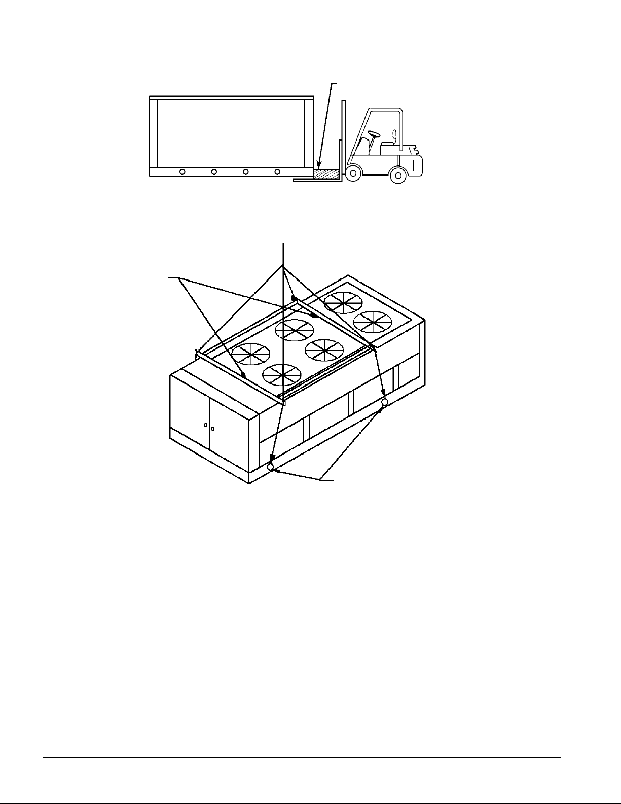
Figure 1, Suggested pushing arrangement
control box location)
Figure 2, Suggested lifting arrangement
Spreader bars
recommended (Use
Caution)
Blocking required
across full width
NOTE: Number of fans can vary
from this diagram. Lifting method
remains the same.
Must use these rigging
holes. (Be aware of
Location
Unit Placement
ALR units are for outdoor applications and can be mounted on a roof or ground level. Set units on a
solid and level foundation. For roof mounted applications, install the unit on a steel channel or Ibeam frame to support the unit above the roof. For ground level applications, install the unit on a
substantial base that will not settle. A one piece concrete slab with footings extended below the frost
line is recommended. Be sure the foundation is level (within 1/2” [13 mm] over its length and
width). The foundation must support the operating weights listed in the Physical Data tables
beginning on page 12.
On ground level applications protect fins against vandalism using the optional coil guards or by
erecting a screen fence. The fence must allow free flow of air to the condenser coil for proper unit
operation.
4 IM 676
Page 5
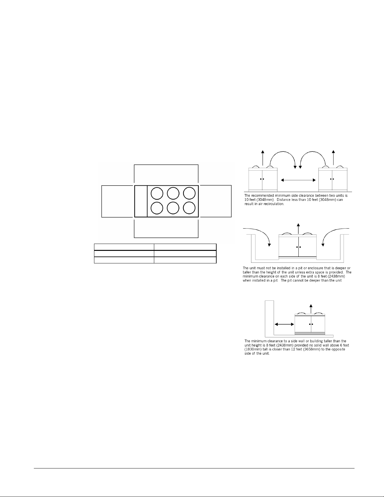
Clearances
air inlet
The flow of air to and from the condenser coil must not be limited. Restricting air flow or allowing
air recirculation will result in a decrease in unit performance and efficiency. There must be no
obstruction above the unit that would deflect discharge air downward where it could be recirculated
back to the inlet of the condenser coil. The condenser fans are propeller type and will not operate
with ductwork on the fan outlet.
Install the unit with enough side clearance for air entrance to the coil and for servicing.
Provide service access to the evaporator, compressors, electrical control panel and piping
components as shown in Figure 3.
Do not allow debris to accumulate near the unit. Air movement may draw debris into the
condenser coil causing air starvation. Give special consideration to low ambient operation where
snow can accumulate. Keep condenser coils and fan discharge free of snow or other obstructions to
permit adequate airflow.
Figure 3, Clearance requirements
5 ft. (1524mm) Clearance for
air inlet
4 Ft.
(1220mm)
clearance for
5 Ft. (1524mm) clearance for
ALR Unit Size Minimum "X" Dimension
032E -075E 8 ft (2438 mm)
080E - 185E 10 ft (3048 mm)
"X" clearance
for evaporator
tube removal
Sound Isolation
The ultra-low sound levels of the ALR reciprocating
chiller is suitable for most applications. When
additional sound reduction is necessary, locate the
unit away from sound sensitive areas. Avoid
locations beneath windows or between structures
where normal operating sounds may be
objectionable. Reduce structurally transmitted sound
by isolating water lines, electrical conduit and the
unit itself. Use wall sleeves and rubber isolated
piping hangers to reduce transmission of water or
pump noise into occupied spaces. Use flexible
electrical conduit to isolate sound through electrical
conduit. Spring isolators are effective in reducing the low amplitude sound generated by
reciprocating compressors and for unit isolation in sound sensitive areas.
Service Access
Each end of the unit must be accessible after installation for periodic service. Compressors, filterdriers, and manual liquid line shutoff valves are accessible on each side of the unit adjacent to the
control box. High pressure, low pressure, and motor protector controls are on the compressor.
Freezestats and cooler barrel thermostats are near the cooler. Most other operational, safety and
starting controls are located in the unit control box.
The condenser fan and motors can be removed from the top of the unit.
IM 676 5
Page 6
Vibration Isolators
Vibration isolators are recommended for all roof mounted installations or wherever vibration
transmission is a consideration.
Table 1 lists isolator loads and type. Table 2 lists spring isolator part numbers for all unit sizes. See
Dimensional Data beginning on page 36 for dimensions required to secure each isolator to the
mounting surface.
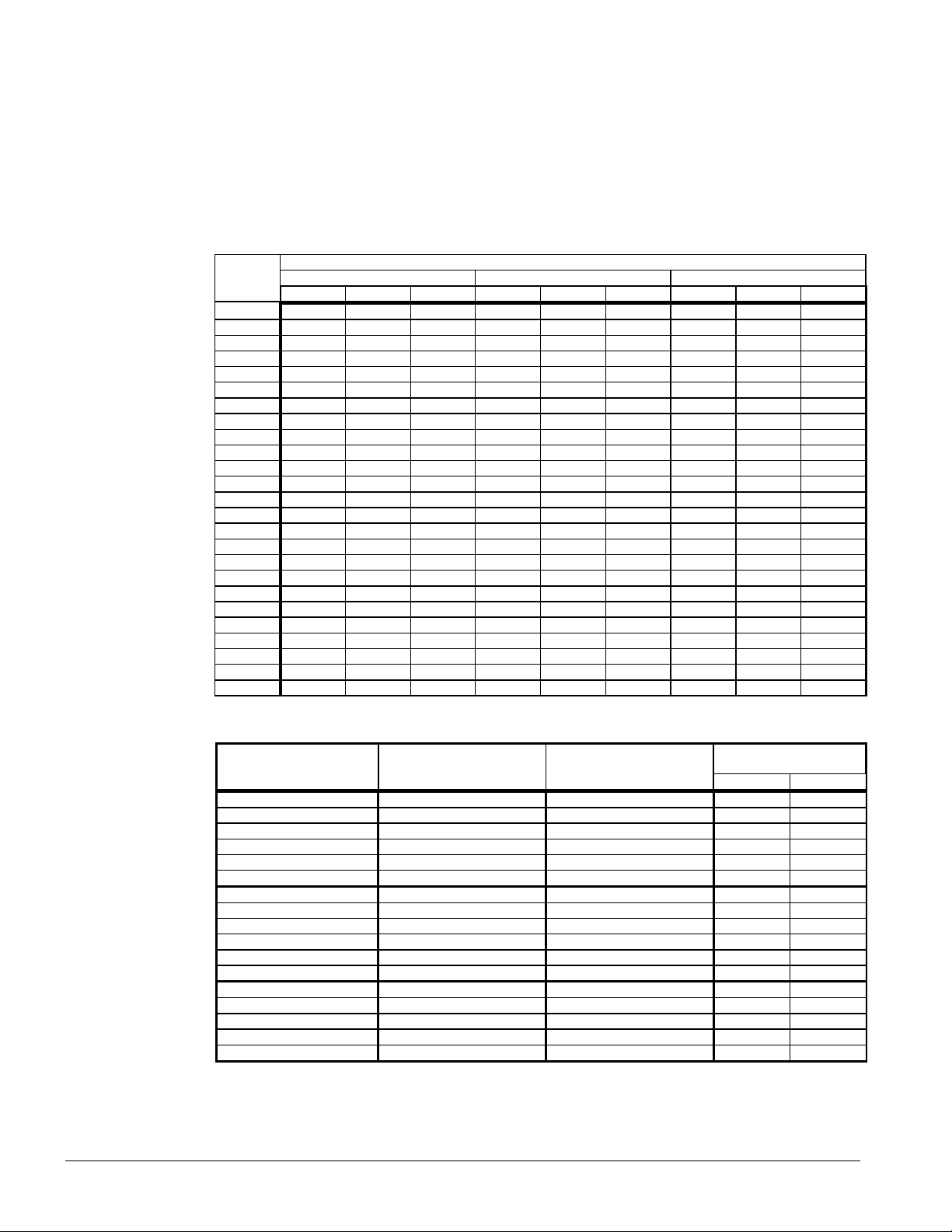
Table 1, Isolator loads and type
ALR ISOLATOR LOADS AND TYPE FOR EACH MOUNTING LOCATION
UNIT R S T
SIZE TYPE LB. KG TYPE LB. KG TYPE LB. KG
032E CP-1-28 669 303 CP-1-28 677 307 CP-1-28 677 307
035E CP-1-28 673 305 CP-1-28 680 308 CP-1-28 680 308
040E CP-1-28 692 314 CP-1-28 699 317 CP-1-28 699 317
045E CP-1-31 804 365 CP-1-31 794 360 CP-1-31 785 356
050E CP-1-31 822 373 CP-1-31 798 362 CP-1-31 800 363
055E CP-1-31 827 375 CP-1-31 819 371 CP-1-31 809 367
060E CP-1-32 850 386 CP-1-32 841 381 CP-1-32 835 379
065E CP-1-32 868 394 CP-1-32 858 389 CP-1-32 848 385
070E CP-1-32 1040 472 CP-1-32 998 453 CP-1-32 912 414
075E CP-1-32 1042 473 CP-1-32 1019 462 CP-1-32 914 415
080E CP-2-28 1110 503 CP-2-28 1122 509 CP-2-31 1296 588
085E CP-2-28 1180 535 CP-2-28 1186 538 CP-2-31 1474 669
090E CP-2-28 1182 536 CP-2-28 1186 538 CP-2-31 1475 669
100E CP-2-28 1193 541 CP-2-28 1214 551 CP-2-31 1508 684
110E CP-2-28 1339 607 CP-2-28 1364 619 CP-2-31 1697 770
120E CP-2-31 1362 618 CP-2-31 1490 676 CP-2-32 1748 793
130E CP-2-31 1492 677 CP-2-32 1570 712 CP-2-32 1838 834
135E CP-2-31 1506 683 CP-2-32 1670 758 CP-2-32 1904 864
140E CP-2-31 1556 706 CP-2-32 1752 795 CP-2-32 1912 867
145E CP-2-31 1572 713 CP-2-32 1680 762 CP-4-27 2093 949
150E CP-2-32 1601 726 CP-2-32 1704 773 CP-4-27 2120 962
160E CP-4-27 1948 884 CP-2-32 1962 890 CP-2-32 1848 838
170E CP-4-27 2052 931 CP-2-32 2002 908 CP-2-32 1849 839
180E CP-4-27 2052 931 CP-2-32 2002 908 CP-2-32 1849 839
185E CP-4-27 2052 931 CP-2-32 2002 908 CP-2-32 1849 839
NOTE: Two of each isolator type is required for a total of six per unit.
Table 2, Spring flex isolator part numbers
TYPE COLOR McQuay Each
Part No. Lb. KG
CP1-25 Red 477927A-25 450 204
CP1-26 Purple 477927A-26 600 272
CP1-27 Orange 477927A-27 750 340
CP1-28 Green 477927A-28 900 408
CP1-31 Gray 477927A-31 1100 499
CP1-32 White 477927A-32 1300 590
CP2-25 Red 477929A-25 900 408
CP2-26 Purple 477929A-26 1200 544
CP2-27 Orange 477929A-27 1500 681
CP2-28 Green 477929A-28 1800 817
CP2-31 Gray 477929A-31 2200 998
CP2-32 White 477929A-32 2600 1180
CP4-26 Purple 580513A-26 2400 1089
CP4-27 Orange 580513A-27 3000 1361
CP4-28 Green 580513A-28 3600 1633
CP4-31 Gray 580513A-31 4400 1996
CP4-32 White 580513A-32 5200 2359
6 IM 676
Max. Load
Page 7
Water Piping
Local authorities can supply the installer with the proper building and safety codes required for safe
and proper installation.
Install piping with minimum bends and changes in elevation to minimize pressure drop.
Consider the following when installing water piping:
1. Vibration eliminators to reduce vibration and noise transmission to the building.
2. Shutoff valves to isolate the unit from the piping system during unit servicing.
3. Manual or automatic air vent valves at the high points of the system. Install drains at the
lowest points in the system.
4. A means of maintaining adequate system water pressure (expansion tank or regulating valve).
5. Temperature and pressure indicators located at the unit to aid in unit servicing.
6. A strainer or other means of removing foreign matter from the water before it enters the pump.
Place the strainer far enough upstream to prevent cavitation at the pump inlet (consult pump
manufacturer for recommendations). The use of a strainer will prolong pump life and keep
system performance up.
7. Place a strainer in the water line just before the inlet of the evaporator. This will help prevent
foreign material from entering and decreasing the performance of the evaporator.
CAUTION
If separate disconnect is used for the 110V supply to the evaporator heating cable, mark
the disconnect clearly to ensure disconnect is not accidentally shut off during cold seasons.
8. The shell-and-tube evaporator has a thermostat and heating cable to prevent freeze-up down to -
20°F (-29°C). It is suggested that the heating cable be wired to a separate 110V supply circuit.
As shipped from the factory, the heating cable is wired to the control circuit. All water piping
to the unit must also be protected to prevent freezing.
9. If the unit is used as a replacement chiller on a previously existing piping system, flush the
system thoroughly before unit installation. Regular water analysis and chemical water
treatment on the evaporator is recommended immediately at equipment start-up.
10. The total water volume in the system should be sufficient to prevent frequent “on-off” cycling.
Turnover rate should not be less than 15 minutes for normal variable cooling loads. Turnover
rate for process cooling or a constant load,should not be less than 6 minutes.
11. When glycol is added to the water system for freeze protection, the refrigerant suction pressure
will be lower, cooling performance less, and water side pressure drop greater. If the percentage
of glycol is high, or if propylene is used instead of ethylene glycol, the added pressure drop and
loss of performance could be substantial. Reset the freezestat and low leaving water alarm
temperatures. The freezestat is factory set to default at 36°F (2.2°C). Reset the freezestat
setting to approximately 4 to 5 degress F (2.3 to 2.8 degress C) below the leaving chilled water
setpoint temperature. See the section titled “Glycol Solutions” for additional information
concerning glycol.
12. Perform a preliminary leak check before insulating the piping and filling the system.
13. Piping insulation should include a vapor barrier to prevent condensation and possible damage
to the building structure.
IM 676 7
Page 8
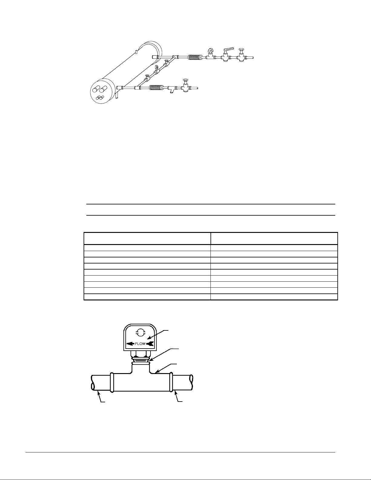
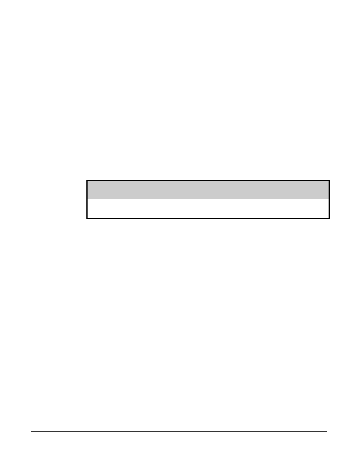
Figure 4, Typical field evaporator water piping
Vent
Outlet
Valved
pressure
gauge
Vibration
Eliminator
Flow
Switch
Balancing
valve
Gate valve
Protect all field piping
against freezing
Drain
Vibration
Eliminator
Water
strainer
Gate valve
Flow Switch
Mount a water flow switch in either the entering or leaving water line to shut down the unit when
water flow is interrupted.
A flow switch is available from McQuay (part number 00175033-00). It is a “paddle” type
switch and adaptable to any pipe size from 3” (76mm) to 8” (203mm) nominal. Certain minimum
flow rates are required to close the switch and are listed in Table 3. Installation should be as shown
in Figure 5. Connect the normally open contacts of the flow switch in the unit control center at
terminals 5 and 6. There is also a set of normally closed contacts on the switch that can be used for
an indicator light or an alarm to indicate when a “no flow” condition exists. Freeze protect any flow
switch that is installed outdoors.
NOTE: Differential pressure switches are not recommended for outdoor installation.
Table 3, Flow switch minimum flow rates
NOMINAL PIPE SIZE MINIMUM REQUIRED FLOW TO
INCHES (MM) ACTIVATE SWITCH - GPM (L/S)
1 (25.4) 6.00 (0.38)
11/4 (31.8) 9.80 (0.62)
11/2 (38.1) 12.70 (0.80)
2 (50.8) 18.80 (1.20)
21/2 (63.50 24.30 (1.50)
3 (76.20 30.00 (1.90)
4 (101.6) 39.70 (2.50)
5 (127.0) 58.70 (3.70)
6 (152.4) 79.20 (5.00)
Figure 5, Flow switch installation
Flow direction
marked on switch
1" (25mm) NPT flow
switch connection
Tee
5" (127mm) pipe dia.
Min. after switch
5" (127mm) pipe dia.
Min. before switch
Water Connections
Bring water piping to the cooler from the bottom of the unit or through the side between the vertical
supports.
8 IM 676
Page 9

Note: The procedure
does not specify the
type of glycol. Use
the derate factors
found in Table 4 for
corrections when
using ethylene glycol
and those in Table 5
for propylene glycol.
Note: On units sizes 160E through 185E there is a diagonal bracket off of a vertical support
which will interfere with the water connection if brought in from the side. This brace can be
removed, but only after the unit is in place.
Refrigerant Charge
All units are designed for use with HCFC-22 and other refrigerants. See nameplate for specific
refrigerant used. Units are shipped with an operating charge. The operating charge
(using HCFC-22) for each unit is shown in the Physical Data tables beginning on page 12.
Glycol Solutions
The system glycol capacity, glycol solution flow rate in GPM, and pressure drop through the cooler
may be calculated using the following formulas and table.
1. Capacity -- Find the reduced capacity by multiplying the chiller’s capacity with water by the
capacity correction factor C.
2. Flow -- To determine evaporator gpm (or Delta-T) knowing Delta-T (or gpm) and capacity:
×
Glycol GPM (from table)=
24 capacity glycol
Delta T
For Metric Applications -- To determine evaporator L/s (or Delta-T) knowing Delta-T (or L/s)
and kW:
Glycol L / s (from table)=
4. 18
kW
× −
Delta T
3. Pressure drop -- To determine pressure drop through the evaporator, when using glycol, enter
the water pressure drop curve on page 11 at the actual glycol GPM. Multiply the water pressure
drop by PD correction factor from Table 4 or Table 5 to obtain corrected glycol pressure drop.
4. To determine the unit's power consumption when using glycol, multiply the water system kW by
factor kW.
Test coolant with a clean, accurate glycol solution hydrometer (similar to that found in service
stations) to determine the freezing point. Obtain percent glycol from the freezing point table below.
On glycol applications it is normally recommended by the supplier that a minimum of 25% solution
by weight be used for protection against corrosion.
( )
−
×
Flow
×
G
IM 676 9
Page 10
CAUTION
Do not use an automotive grade antifreeze. Industrial grade glycols must be used.
Automotive antifreeze contains inhibitors which will cause plating on the copper tubes
within the chiller evaporator. The type and handling of glycol used must be consistent with
local codes.
Table 4, Ethylene glycol
% Freeze Point
E.G. °F °C Cap. kW GPM PD
10 26 -3 0.991 0.996 1.013 1.070
20 18 -8 0.982 0.992 1.040 1.129
30 7 -14 0.972 0.986 1.074 1.181
40 -7 -22 0.961 0.976 1.121 1.263
50 -28 -33 0.946 0.966 1.178 1.308
Table 5, Propylene glycol
% Freeze Point
P.G. °F °C Cap. kW GPM PD
10 26 -3 0.987 0.992 1.010 1.068
20 19 -7 0.975 0.985 1.028 1.147
30 9 -13 0.962 0.978 1.050 1.248
40 -5 -21 0.946 0.971 1.078 1.366
50 -27 -33 0.929 0.965 1.116 1.481
Table 6, Capacity and power derates
Chilled Water Fouling Factor
ALTITUDE °F °C Cap. kW Cap. kW Cap. kW
SEA 10 5.6 1.000 1.000 0.975 0.986 0.919 0.939
LEVEL 12 6.7 1.005 1.002 0.980 0.989 0.923 0.941
2000 feet 12 6.7 0.992 1.011 0.970 0.998 0.914 0.949
4000 feet 12 6.7 0.978 1.025 0.956 1.008 0.904 0.958
6000 feet 12 6.7 0.963 1.034 0.942 1.017 0.895 0.966
Delta-T 0.00025 (0.044) 0.00075 (0.132) 0.00175 (0.308)
6 3.3 0.992 0.995 0.996 0.982 0.911 0.935
8 4.4 0.995 0.997 0.969 0.984 0.914 0.937
14 6.8 1.010 1.005 0.985 0.991 0.928 0.943
16 8.9 1.014 1.007 0.989 0.993 0.930 0.944
6 3.3 0.978 1.005 0.957 0.990 0.903 0.943
8 4.4 0.982 1.007 0.961 0.993 0.905 0.945
10 5.6 0.986 1.009 0.965 0.995 0.909 0.947
14 6.8 0.997 1.014 0.973 1.001 0.919 0.952
16 8.9 1.000 1.016 0.975 1.002 0.921 0.953
6 3.3 0.966 1.016 0.944 0.999 0.894 0.951
8 4.4 0.969 1.018 0.947 1.001 0.896 0.953
10 5.6 0.973 1.021 0.952 1.005 0.900 0.956
14 6.8 0.982 1.027 0.959 1.011 0.909 0.960
16 8.9 0.986 1.028 0.961 1.015 0.911 0.961
6 3.3 0.953 1.025 0.930 1.009 0.884 0.961
8 4.4 0.955 1.028 0.934 1.011 0.887 0.962
10 5.6 0.959 1.031 0.939 1.013 0.890 0.964
14 6.8 0.968 1.036 0.946 1.020 0.899 0.968
16 8.9 0.972 1.037 0.949 1.024 0.902 0.969
10 IM 676
Page 11
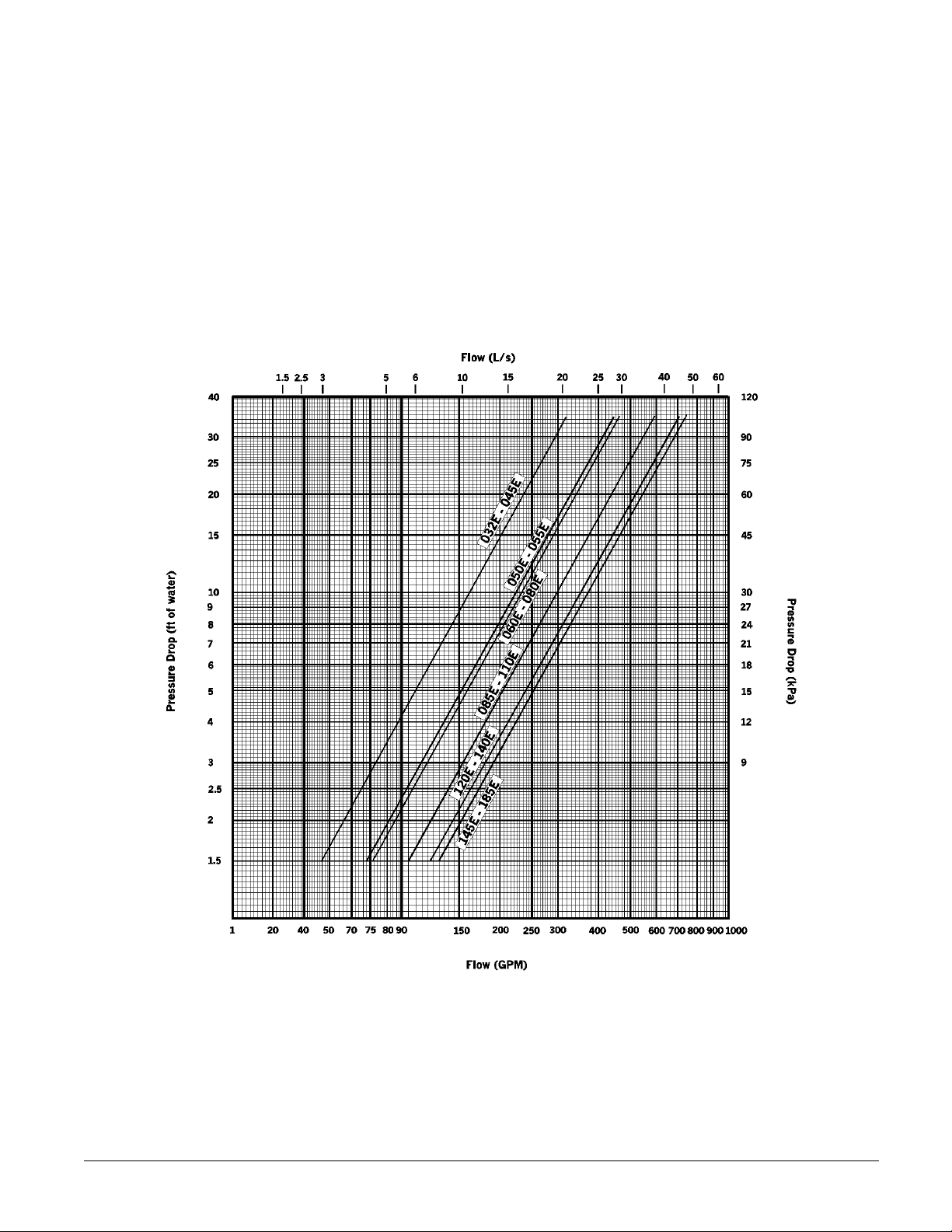
Evaporator Water Flow and Pressure Drop
Evaporator flow rate must fall between the minimum and maximum values shown in the evaporator
pressure drop curve. Flow rates below the minimum values will result in laminar flow which will
reduce efficiency, cause erratic operation of the expansion valve and could cause low temperature
cutouts. Flow rates exceeding the maximum values can cause erosion on the evaporator water
connections and tubes.
Measure the chilled water pressure drop through the evaporator at field installed pressure taps.
It is important not to include the effect of valves or strainers in these readings.
Varying chilled water flow through the evaporator while the compressor(s) are operating is not
recommended.
Figure 6, Evaporator water pressure drop curve
IM 676 11
Page 12
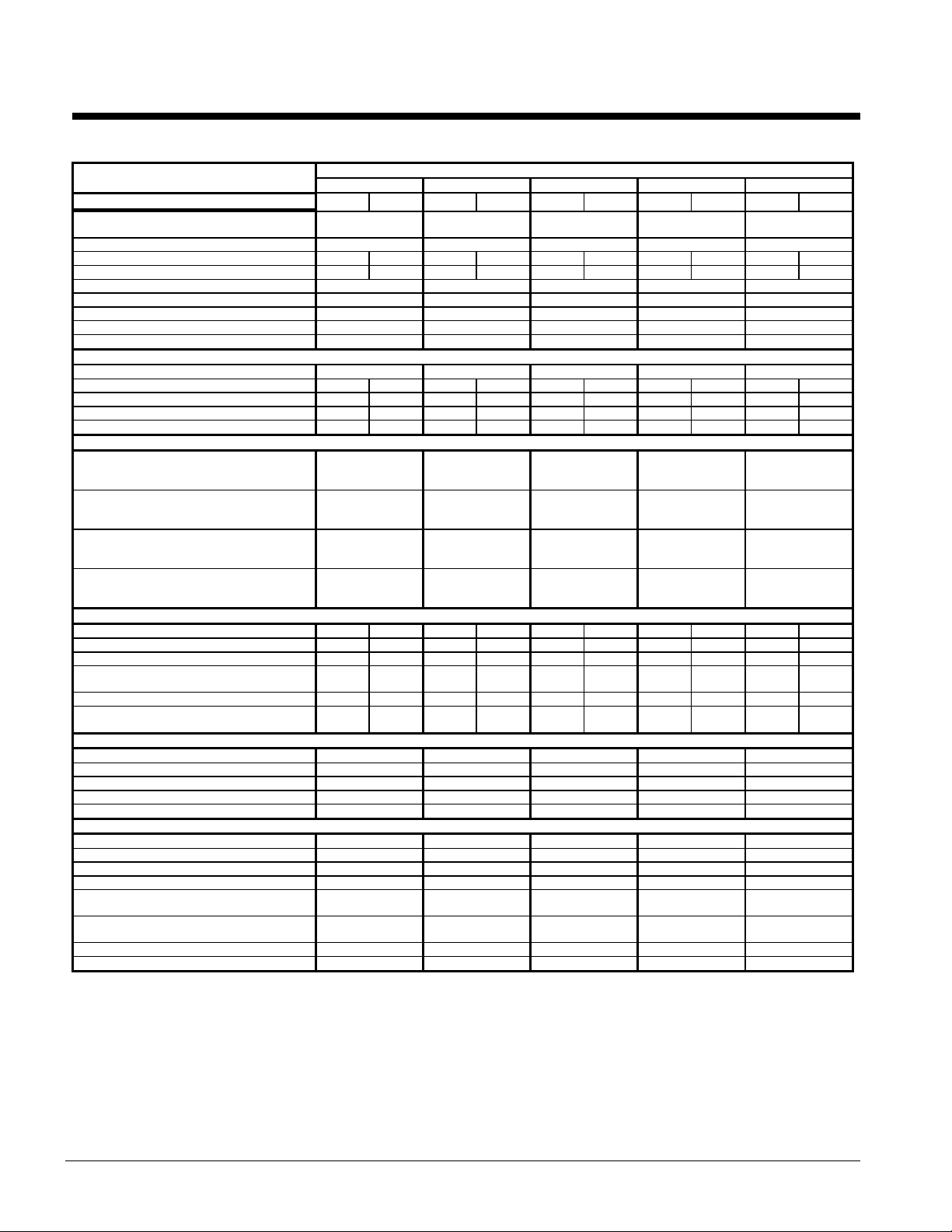
Physical Data
Table 7 , Physical data ALR032E Through 050E
PHYSICAL DATA ALR MODEL NUMBER
BASIC DATA Ckt.1 Ckt.2 Ckt.1 Ckt.2 Ckt.1 Ckt.2 Ckt.1 Ckt.2 Ckt.1 Ckt.2
Unit Capacity @ ARI Conditions (1),
Tons (kW)
Number Of Refrigerant Circuits 2 2 2 2 2
Unit Operating Charge, R-22, lb. 20 20 23 23 30 30 32 32 32 32
Unit Operating Charge, R-22, (kg) (9.1) (9.1) (11.3) (11.3) (13.6) (13.6) (13.6) (13.6) (13.6) (13.6)
Cabinet Dimensions, LxWxH, In. 123 x 83 x 59 123 x 83 x 59 123 x 83 x 59 176 x 83 x 59 176 x 83 x 59
Cabinet Dimensions, LxWxH, (mm) (3124 x 2108 x 1499) (3124 x 2108 x 1499) (3124 x 2108 x 1499) (4470 x 2108 x 1499) (4470 x 2108 x 1499)
Unit Operating Weight, Lb. (kg) 4045 (1835) 4065(1853) 4180 (1896) 4765 (2162) 4840 (2196)
Unit Shipping Weight, Lb. (kg) 3895 (1767) 3915 (1785) 4030 (1828) 4615 (2094) 4690 (2127)
Add'l Weight If Copper Finned Coils, Lb. (kg) 270 (122) 270 (122) 370 (168) 410 (186) 410 (186)
COMPRESSORS
Type Semi-Hermetic Semi-Hermetic Semi-Hermetic Semi-Hermetic Semi-Hermetic
Nominal Horsepower 20 20 20 22 25 25 25 30 30 30
Number Of Cylinders Per Compressor 4 4 4 4 4 4 4 6 4 6
Oil Charge Per Compressor, Oz. 130 130 130 130 130 130 130 140 140 140
Oil Charge Per Compressor, (g) (3686) (3686) (3686) (3686) (3686) (3686) (3686) (3969) (3969) (3969)
CAPACITY REDUCTION STEPS - PERCENT OF COMPRESSOR DISPLACEMENT
Standard Staging - Circuit #1 in Lead
Standard 4 Stages 0-25-50-75-100 0-22-50-72-100 0-25-50-75-100 0-21-60-81-100 0-23-59-82-100
Standard Staging - Circuit #2 in Lead
Standard 4 Stages 0-25-50-75-100 0-28-50-78-100 0-25-50-75-100 0-39-60-79-100 0-36-59-77-100
Optional Staging - Circuit #1 in Lead
Optional 6 Stages N/A N/A N/A N/A N/A
032E 035E 040E 045E 050E
32.5 (114.3) 34.6 (121.7) 40.4 (142.0) 45.9 (161.4) 50.8 (178.6)
Optional Staging - Circuit #2 in Lead
Optional 6 Stages N/A N/A N/A N/A N/A
CONDENSERS - HIGH EFFICIENCY FIN AND TUBE TYPE WITH INTEGRAL SUBCOOLING
Maximum Relief Valve Pressure Setting, psig
CONDENSER FANS - DIRECT DRIVE PROPELLER TYPE
Number Of Fans - Fan Diameter, In. (mm) 4 - 26 (660) 4 - 26 (660) 4 - 26 (660) 6 - 26 (660) 6 - 26 (660)
DIRECT EXPANSION EVAPORATOR - BAFFLED SHELL AND THRU-TUBE
Maximum Refrigerant Working Pressure, psig
Water Inlet / Outlet Victaulic Connections,
NOTE:
1. Nominal capacity based on 95F ambient air and 54F/44F water range.
Coil Face Area,Sq. Ft. 28.3 28.3 28.3 28.3 28.3 28.3 43.1 43.1 43.1 43.1
Coil Face Area, (M2) (2.6) (2.6) (2.6) (2.6) (2.6) (2.6) (4) (4) (4) (4)
Finned Height x Finned Length, In. 40 x 102 40 x 102 40 x 102 40 x 102 40 x 102 40 x 102 40 x 155 40 x 155 40 x 155 40 x 155
Finned Height x Finned Length, (mm) (1016 x
Fins Per Inch x Rows Deep 16 x 2 16 x 2 16 x 2 16 x 2 16 x 3 16 x 3 16 x 2 16 x 2 16 x 2 16 x 2
(kPa)
Number Of Motors - HP (kW) 4 - 1.0 (.7) 4 - 1.0 (.7) 4 - 1.0 (.7) 6 - 1.0 (.7) 6 - 1.0 (.7)
Fan And Motor RPM, 60/50Hz 1100/915 1100/915 1100/915 1100/915 1100/915
60 Hz Fan Tip Speed, FPM 7760 7760 7760 7760 7760
60 Hz Total Unit Airflow, CFM 28400 29840 26980 42000 42000
Diameter, in. - Length, Ft. 10 - 08 10 - 08 10 - 08 10 - 08 12 - 08
Diameter, (mm) - Length, (mm) (254 - 2439) (254 - 2439) (254 - 2439) (254 - 2439) (305 - 2439)
Water Volume, Gallons, (L) 17.90 (67.8) 17.90 (67.8) 17.90 (67.8) 17.90 (67.8) 24.30 (92)
Maximum Water Pressure, psig (kPa) 175 (1207) 175 (1207) 175 (1207) 175 (1207) 175 (1207)
(kPa)
In. (mm)
Drain - NPT int, In. (mm) .375 (9.5) .375 (9.5) .375 (9.5) .375 (9.5) .375 (9.5)
Vent - NPT int, In. (mm) .375 (9.5) .375 (9.5) .375 (9.5) .375 (9.5) .375 (9.5)
2591)
(3103)
(1016 x
2591)
450
(3103)
225 (1552) 225 (1552) 225 (1552) 225 (1552) 225 (1552)
4 (101.6) 4 (101.6) 4 (101.6) 4 (101.6) 5 (127)
450
(1016 x
2591)
450
(3103)
(1016 x
2591)
450
(3103)
(1016 x
2591)
450
(3103)
(1016 x
2591)
450
(3103)
(1016 x
3937)
450
(3103)
(1016 x
3937)
450
(3103)
(1016 x
3937)
450
(3103)
(1016 x
3937)
450
(3103)
12 IM 676
Page 13
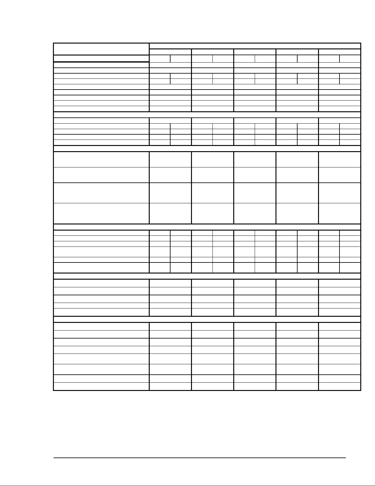
Table 8, Physical data ALR055E Through 075E
PHYSICAL DATA ALR MODEL NUMBER
BASIC DATA Ckt.1 Ckt.2 Ckt.1 Ckt.2 Ckt.1 Ckt.2 Ckt.1 Ckt.2 Ckt.1 Ckt.2
Unit Capacity @ ARI Conditions (1), Tons (kW) 54.6 (192.0) 59.6 (209.6) 64.0 (225.0) 69.0 (242.6) 72.2 (253.9)
Number Of Refrigerant Circuits 2 2 2 2 2
Unit Operating Charge, R-22, Lb. 45 45 45 45 45 45 58 58 60 60
Unit Operating Charge, R-22, (kg) (15.9) (15.9) (15.9) (15.9) (18.1) (18.1) (18.1) (18.1) (20.4) (20.4)
Cabinet Dimensions, LxWxH, In. 176 x 83 x 59 176 x 83 x 59 176 x 83 x 59 229 x 83 x 59 229 x 83 x 59
Cabinet Dimensions, LxWxH, (mm) (4470 x 2108 x 1499) (4470 x 2108 x 1499) (4470 x 2108 x 1499) (5817 x 2108 x 1499) (5817 x 2108 x 1499)
Unit Operating Weight, Lb. (kg) 4910 (2228) 5052 (2292) 5148 (2335) 5900 (2677) 5950 (2700)
Unit Shipping Weight, Lb. (kg) 4760 (2160) 4850 (2200) 4946 (2244) 5635 (2556) 5685 (2579)
Add'l Weight If Copper Finned Coils, Lb. (kg) 410 (186) 615 (279) 615 (279) 825 (374) 825 (374)
COMPRESSORS
Type Semi-Hermetic Semi-Hermetic Semi-Hermetic Semi-Hermetic Semi-Hermetic
Nominal Horsepower 30 30 30 35 35 35 35 40 40 40
Number Of Cylinders Per Compressor 6 6 6 6 6 6 6 6 6 6
Oil Charge Per Compressor, Oz. 140 140 140 140 140 140 140 255 255 255
Oil Charge Per Compressor, (g) (3969) (3969) (3969) (3969) (3969) (3969) (3969) (7229) (7229) (7229)
CAPACITY REDUCTION STEPS - PERCENT OF COMPRESSOR DISPLACEMENT
Standard Staging - Circuit #1 in Lead
Standard 4 Stages 0-33-50-83-100 0-30-67-82-100 0-33-50-83-100 0-32-67-83-100 0-33-50-83-100
Standard Staging - Circuit #2 in Lead
Standard 4 Stages 0-33-50-83-100 0-36-67-85-100 0-33-50-83-100 0-35-67-84-100 0-33-50-83-100
Optional Staging - Circuit #1 in Lead
Optional 6 Stages 0-17-33-50-67-83-
Optional Staging - Circuit #2 in Lead
Optional 6 Stages 0-17-33-50-67-83-
055E 060E 065E 070E 075E
100
100
0-15-33-48-67-82-
100
0-18-33-51-67-85-
100
0-17-33-50-67-83-
100
0-17-33-50-67-83-
100
0-16-33-49-67-83-
100
0-17-33-51-67-84-
100
0-17-33-50-67-83-
100
0-17-33-50-67-83-
100
CONDENSERS - HIGH EFFICIENCY FIN AND TUBE TYPE WITH INTEGRAL SUBCOOLING
Maximum Relief Valve Pressure Setting, psig
CONDENSER FANS - DIRECT DRIVE PROPELLER TYPE
Number Of Fans - Fan Diameter, In. (mm) 6 - 26 (660) 6 - 26 (660) 6 - 26 (660) 8 - 26 (660) 10 - 26 (660)
DIRECT EXPANSION EVAPORATOR - BAFFLED SHELL AND THRU-TUBE
Maximum Refrigerant Working Pressure, psig
Water Inlet / Outlet Victaulic Connections,
NOTE:
1. Nominal capacity based on 95F ambient air and 54F/44F water range.
Coil Face Area,Sq. Ft. 43.1 43.1 43.1 43.1 43.1 43.1 57.8 57.8 57.8 57.8
Coil Face Area, (M2) (4) (4) (4) (4) (4) (4) (5.4) (5.4) (5.4) (5.4)
Finned Height x Finned Length, In. 40 x 155 40 x 155 40 x 155 40 x 155 40 x 155 40 x 155 40 x 208 40 x 208 40 x 208 40 x 208
Finned Height x Finned Length, (mm) (1016 x
Fins Per Inch x Rows Deep 16 x 3 16 x 3 16 x 3 16 x 3 16 x 3 16 x 3 16 x 3 16 x 3 16 x 3 16 x 3
(kPa)
Number Of Motors - HP (kW) 6 - 1.0 (.7) 6 - 1.0 (.7) 6 - 1.0 (.7) 8 - 1.0 (.7) 10 - 1.0 (.7)
Fan And Motor RPM, 60/50Hz 1100/915 1100/915 1100/915 1100/915 1100/915
60 Hz Fan Tip Speed, FPM 7760 7760 7760 7760 7760
60 Hz Total Unit Airflow, CFM 38250 38250 38250 51000
Diameter, in. - Length, Ft. 12 - 08 12 - 08 12 - 08 12 - 08 12 - 08
Diameter, (mm) - Length, (mm) (305 - 2439) (305 - 2439) (305 - 2439) (305 - 2439) (305 - 2439)
Water Volume, Gallons, (L) 24.30 (92) 24.30 (92) 24.30 (92) 24.30 (92) 24.30 (92)
Maximum Water Pressure, psig (kPa) 175 (1207) 175 (1207) 175 (1207) 175 (1207) 175 (1207)
(kPa)
In. (mm)
Drain - NPT int, In. (mm) .375 (9.5) .375 (9.5) .375 (9.5) .375 (9.5) .375 (9.5)
Vent - NPT int, In. (mm) .375 (9.5) .375 (9.5) .375 (9.5) .375 (9.5) .375 (9.5)
3937)
(3103)
(1016 x
3937)
450
(3103)
225 (1552) 225 (1552) 225 (1552) 225 (1552) 225 (1552)
5 (127) 5 (127) 5 (127) 5 (127) 5 (127)
450
(1016 x
3937)
450
(3103)
(1016 x
3937)
450
(3103)
(1016 x
3937)
450
(3103)
(1016 x
3937)
450
(3103)
(1016 x
5283)
450
(3103)
(1016 x
5283)
450
(3103)
(1016 x
5283)
450
(3103)
(1016 x
5283)
450
(3103)
58000
IM 676 13
Page 14
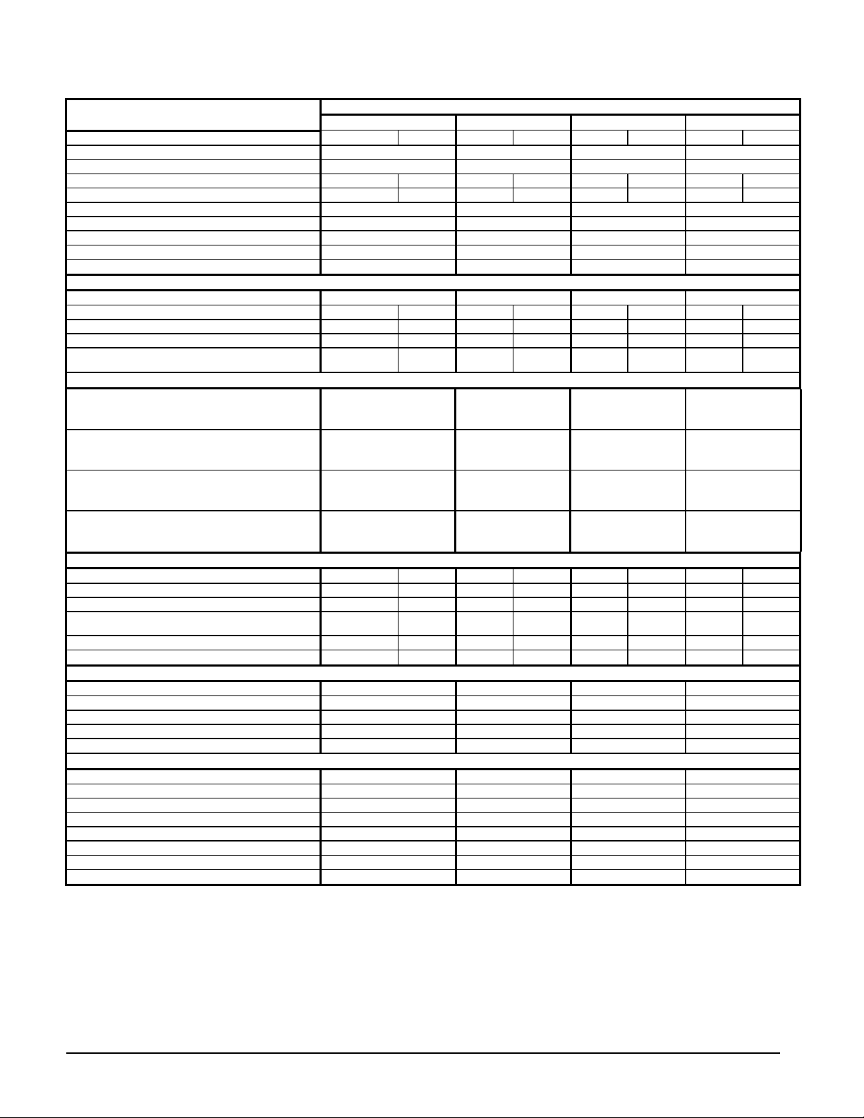
Table 9, Physical data ALR080E Through 100E
PHYSICAL DATA ALR MODEL NUMBER
080E 085E 090E 100E
BASIC DATA Ckt.1 Ckt.2 Ckt.1 Ckt.2 Ckt.1 Ckt.2 Ckt.1 Ckt.2
Unit Capacity @ ARI Conditions (1), Tons (kW) 81.3 (285.9) 85.3 (300.0) 92.7 (326.0) 99.2 (348.8)
Number Of Refrigerant Circuits 2 2 2 2
Unit Operating Charge, R-22, Lb. 62 62 65 65 65 65 68 68
Unit Operating Charge, R-22, (kg) (22.7) (22.7) (22.7) (22.7) (24.9) (24.9) (24.9) (24.9)
Cabinet Dimensions, LxWxH, In. 229 x 83 x 59 229 x 83 x 59 229 x 83 x 59 229 x 83 x 59
Cabinet Dimensions, LxWxH, (mm) (5817 x 2108 x 1499) (5817 x 2108 x 1499) (5817 x 2108 x 1499) (5817 x 2108 x 1499)
Unit Operating Weight, Lbs. (kg) 7055 (3200) 7680 (3484) 7685 (3486) 7830 (3552)
Unit Shipping Weight, Lbs. (kg) 6685 (3032) 7310 (3316) 7315 (3318) 7535 (3418)
Add'l Weight If Copper Finned Coils, Lb. (kg) 826 (375) 826 (375) 826 (375) 826 (375)
COMPRESSORS
Type Semi-Hermetic Semi-Hermetic Semi-Hermetic Semi-Hermetic
Nominal Horsepower 25-25 25-25 25-25 30-25 30-25 30-25 30-30 30-30
Number Of Cylinders Per Compressor 4 - 4 4 - 4 4 - 4 4 - 4 6 - 4 6 - 4 6 - 4 6 - 4
Oil Charge Per Compressor, Oz. 130 - 130 130 - 130 130 - 130 140 - 130 140 - 130 140 - 130 140 - 140 140 - 140
Oil Charge Per Compressor, (g) (3686 - 3686) (3686 -
3686)
CAPACITY REDUCTION STEPS - PERCENT OF COMPRESSOR DISPLACEMENT
Standard Staging - Circuit #1 in Lead
Standard 6 Stages 0-13-25-38-50-75-100 0-12-24-36-48-72-100 0-19-39-48-58-79-100 0-18-36-45-54-76-100
Standard Staging - Circuit #2 in Lead
Standard 6 Stages 0-13-25-38-50-75-100 0-12-24-36-48-76-100 0-19-39-48-58-79-100 0-18-36-45-54-76-100
Optional Staging - Circuit #1 in Lead
Optional 8 Stages 0-13-25-38-50 0-12-24-36-48 0-19-39-48-58 0-18-36-45-76
-63-75-88-100 -60-76-88-100 -69-81-90-100 -68-82-91-100
Optional Staging - Circuit #2 in Lead
Optional 8 Stages 0-13-25-38-50 0-12-24-36-48 0-19-39-48-58 0-18-36-45-76
-63-75-88-100 -64-76-88-100 -69-81-90-100 -68-82-91-100
CONDENSERS - HIGH EFFICIENCY FIN AND TUBE TYPE WITH INTEGRAL SUBCOOLING
Coil Face Area,Sq. Ft. 57.8 57.8 57.8 57.8 57.8 57.8 57.8 57.8
Coil Face Area, (M2) (5.4) (5.4) (5.4) (5.4) (5.4) (5.4) (5.4) (5.4)
Finned Height x Finned Length, In. 40 x 208 40 x 208 40 x 208 40 x 208 40 x 208 40 x 208 40 x 208 40 x 208
Finned Height x Finned Length, (mm) (1016 x 5283) (1016 x
5283)
Fins Per Inch x Rows Deep 16 x 3 16 x 3 16 x 3 16 x 3 16 x 3 16 x 3 16 x 3 16 x 3
Maximum Relief Valve Pressure Setting, psig (kPa) 450 (3103) 450 (3103) 450 (3103) 450 (3103) 450 (3103) 450 (3103) 450 (3103) 450 (3103)
CONDENSER FANS - DIRECT DRIVE PROPELLER TYPE
Number Of Fans - Fan Diameter, In. (mm) 10 - 26 (660) 10 - 26 (660) 10 - 26 (660) 10 - 26 (660)
Number Of Motors - HP (kW) 10 - 1.0 (.7) 10 - 1.0 (.7) 10 - 1.0 (.7) 10 - 1.0 (.7)
Fan And Motor RPM, 60/50Hz 1100/915 1100/915 1100/915 1100/915
60 Hz Fan Tip Speed, FPM 7760 7760 7760 7760
60 Hz Total Unit Airflow, CFM 58000 58000 58000 58000
DIRECT EXPANSION EVAPORATOR - BAFFLED SHELL AND THRU-TUBE
Diameter, in. - Length, Ft. 12 - 08 14 - 10 14 - 10 14 - 10
Diameter, (mm) - Length, (mm) (305 - 2439) (356 - 3048) (356 - 3048) (356 - 3048)
Water Volume, Gallons, (L) 24.30 (92) 36.10 (136.6) 36.10 (136.6) 36.10 (136.6)
Maximum Water Pressure, psig (kPa) 175 (1207) 175 (1207) 175 (1207) 175 (1207)
Maximum Refrigerant Working Pressure, psig (kPa) 225 (1552) 225 (1552) 225 (1552) 225 (1552)
Water Inlet / Outlet Victaulic Connections, In. (mm) 5 (127) 6 (152.4) 6 (152.4) 6 (152.4)
Drain - NPT int, In. (mm) .375 (9.5) .375 (9.5) .375 (9.5) .375 (9.5)
Vent - NPT int, In. (mm) .375 (9.5) .375 (9.5) .375 (9.5) .375 (9.5)
NOTE:
1. Nominal capacity based on 95F ambient air and 54F/44F water range.
(3686 -
3686)
(1016 x
5283)
(3969 -
3686)
(1016 x
5283)
(3969 -
3686)
(1016 x
5283)
(3969 -
3686)
(1016 x
5283)
(3969 -
3969)
(1016 x
5283)
(3969 -
3969)
(1016 x
5283)
14 IM 676
Page 15

Table 10, Physical data ALR100E Through 135E
PHYSICAL DATA ALR MODEL NUMBER
110E 120E 130E 135E
BASIC DATA Ckt.1 Ckt.2 Ckt.1 Ckt.2 Ckt.1 Ckt.2 Ckt.1 Ckt.2
Unit Capacity @ ARI Conditions (1), Tons (kW) 107.8 (379.0) 120.7 (424.4) 130.6 (459.2) 135.5 (476.4)
Number Of Refrigerant Circuits 2 2 2 2
Unit Operating Charge, R-22, Lb. 87 87 90 90 120 120 120 120
Unit Operating Charge, R-22, (kg) (36.3) (36.3) (36.3) (36.3) (38.6) (38.6) (38.6) (38.6)
Cabinet Dimensions, LxWxH, In. 229 x 83 x 89 229 x 83 x 89 229 x 83 x 93 229 x 83 x 93
Cabinet Dimensions, LxWxH, (mm) (5809 x 2118 x 2369) (5809 x 2118 x 2369) (5809 x 2118 x 2369) (5809 x 2118 x 2369)
Unit Operating Weight, Lbs. (kg) 8800 (3992) 9200 (4173) 9800 (4445) 10160 (4609)
Unit Shipping Weight, Lbs. (kg) 8505 (3858) 8760 (3974) 9350 (4241) 9735 (4416)
Add'l Weight If Copper Finned Coils, Lbs. (kg) 1105 (501) 1105 (501) 1652 (750) 1652 (750)
COMPRESSORS
Type Semi-Hermetic Semi-Hermetic Semi-Hermetic Semi-Hermetic
Nominal Horsepower 30-30 30-35 30-35 35-35 35-35 35-35 35-40 35-40
Number Of Cylinders Per Compressor 6 - 6 6 - 6 6 - 6 6 - 6 6 - 6 6 - 6 6 - 6 6 - 6
Oil Charge Per Compressor, Oz. 140 - 140 140 - 140 140 - 140 140 - 140 140 - 140 140 - 140 140 - 255 140 - 255
Oil Charge Per Compressor, (g) (3969 -
3969)
CAPACITY REDUCTION STEPS - PERCENT OF COMPRESSOR DISPLACEMENT
Standard Staging - Circuit #1 in Lead
Standard 6 Stages 0-16-32-40-48-71-100 0-15-32-39-48-74-100 0-17-33-42-50-75-100 0-16-32-40-48-74-100
Standard Staging - Circuit #2 in Lead
Standard 6 Stages 0-16-32-40-48-76-100 0-17-32-41-48-76-100 0-17-33-42-50-75-100 0-16-32-40-48-74-100
(3969 -
3969)
(3969 -
3969)
(3969 -
3969)
(3969 -
3969)
(3969 -
3969)
(3969 -
7229)
(3969 -
7229)
Optional Staging - Circuit #1 in Lead
Optional 8 Stages 0-16-32-40-48 0-15-32-39-48 0-17-33-42-50 0-16-32-40-48
-64-84-92-100 -67-84-91-100 -67-83-92-100 -66-84-92-100
Optional Staging - Circuit #2 in Lead
Optional 8 Stages 0-16-32-40-48 0-17-32-41-48 0-17-33-42-50 0-16-32-40-48
-68-84-92-100 -65-84-91-100 -67-83-92-100 -66-84-92-100
CONDENSERS - HIGH EFFICIENCY FIN AND TUBE TYPE WITH INTEGRAL SUBCOOLING
Coil Face Area,Sq. Ft. 115.6 115.6 115.6 115.6 115.6 115.6 115.6 115.6
Coil Face Area, (M2) (10.3) (10.3) (10.3) (10.3) (10.3) (10.3) (10.3) (10.3)
Finned Height x Finned Length, In. 80 x 208 80 x 208 80 x 208 80 x 208 80 x 208 80 x 208 80 x 208 80 x 208
Finned Height x Finned Length, (mm) (2032 x
5283)
Fins Per Inch x Rows Deep 16 x 2 16 x 2 16 x 2 16 x 2 16 x 3 16 x 3 16 x 3 16 x 3
Maximum Relief Valve Pressure Setting, psig (kPa) 450 (3103) 450 (3103) 450 (3103) 450 (3103) 450 (3103) 450 (3103) 450 (3103) 450 (3103)
CONDENSER FANS - DIRECT DRIVE PROPELLER TYPE
Number Of Fans - Fan Diameter, In. (mm) 10 - 28 (711) 10 - 28 (711) 12 - 28 (711) 12 - 28 (711)
Number Of Motors - HP (kW) 10 - 1.5 (1.1) 10 - 1.5 (1.1) 12 - 1.5 (1.1) 12 - 1.5 (1.1)
Fan And Motor RPM, 60/50Hz 1100/915 1100/915 1100/915 1100/915
60 Hz Fan Tip Speed, FPM 8063 8063 8063 8063
60 Hz Total Unit Airflow, CFM 94710 94710 108240 108240
DIRECT EXPANSION EVAPORATOR - BAFFLED SHELL AND THRU-TUBE
Diameter, in. - Length, Ft. 14 - 10 16 - 10 16 - 10 16 - 10
Diameter, (mm) - Length, (mm) (356 - 3048) (406 - 3048) (406 - 3048) (406 - 3048)
Water Volume, Gallons, (L) 36.10 (136.6) 43.6 (165) 43.6 (165) 43.6 (165)
Maximum Water Pressure, psig (kPa) 175 (1207) 175 (1207) 175 (1207) 175 (1207)
Maximum Refrigerant Working Pressure, psig (kPa) 225 (1552) 225 (1552) 225 (1552) 225 (1552)
Water Inlet / Outlet Victaulic Connections, In. (mm) 6 (152.4) 6 (152.4) 6 (152.4) 6 (152.4)
Drain - NPT int, In. (mm) .375 (9.5) .375 (9.5) .375 (9.5) .375 (9.5)
Vent - NPT int, In. (mm) .375 (9.5) .375 (9.5) .375 (9.5) .375 (9.5)
NOTE:
1. Nominal capacity based on 95F ambient air and 54F/44F water range.
(2032 x
5283)
(2032 x
5283)
(2032 x
5283)
(2032 x
5283)
(2032 x
5283)
(2032 x
5283)
(2032 x
5283)
IM 676 15
Page 16

Table 11, Physical data ALR140E Through 160E
PHYSICAL DATA ALR MODEL NUMBER
140E 145E 150E 160E
BASIC DATA Ckt.1 Ckt.2 Ckt.1 Ckt.2 Ckt.1 Ckt.2 Ckt.1 Ckt.2
Unit Capacity @ ARI Conditions (1), Tons (kW) 139.7 (491.2) 144.7 (508.8) 149.9 (527.0) 157.8 (554.8)
Number Of Refrigerant Circuits 2 2 2 2
Unit Operating Charge, R-22, Lbs 125 125 130 130 130 130 140 140
Unit Operating Charge, R-22, (kg) (45.4) (45.4) (45.4) (45.4) (45.4) (45.4) (49.9) (49.9)
Cabinet Dimensions, LxWxH, In. 229 x 83 x 93 229 x 83 x 93 229 x 83 x 93 263 x 83 x 93
Cabinet Dimensions, LxWxH, (mm) (5809 x 2118 x 2369) (5809 x 2118 x 2369) (5809 x 2118 x 2369) (6690 x 2118 x 2369)
Unit Operating Weight, Lbs. (kg) 10440 (4736) 10690 (4849) 10850 (4922) 11515 (5223)
Unit Shipping Weight, Lbs. (kg) 10040 (4554) 10290 (4668) 10450 (4740) 11115 (5042)
Add'l Weight If Copper Finned Coils, Lb. (kg) 1652 (750) 1652 (750) 1652 (750) 1930 (876)
COMPRESSORS
Type Semi-Hermetic Semi-Hermetic Semi-Hermetic Semi-Hermetic
Nominal Horsepower 40-40 40-40 40-40 40-40 40-40 40-50 40-50 40-50
Number Of Cylinders Per Compressor 6 - 6 6 - 6 6 - 6 6 - 6 6 - 6 6 - 8 6 - 8 6 - 8
Oil Charge Per Compressor, Oz. 255 - 255 255 - 255 255 - 255 255 - 255 255 - 255 255 - 255 255 - 255 255 - 255
Oil Charge Per Compressor, (g) (7229 -
7229)
CAPACITY REDUCTION STEPS - PERCENT OF COMPRESSOR DISPLACEMENT
Standard Staging - Circuit #1 in Lead
Standard 6 Stages (N/A on MicroTech Units) 0-17-33-42-50-75-100 0-17-33-42-50-75-100 0-15-32-40-48-72-100 0-17-33-42-50-77-100
Standard Staging - Circuit #2 in Lead
Standard 6 Stages (N/A on MicroTech Units) 0-17-33-42-50-75-100 0-17-33-42-50-75-100 0-15-32-40-48-76-100 0-17-33-42-50-77-100
(7229 -
7229)
(7229 -
7229)
(7229 -
7229)
(7229 -
7229)
(7229 -
7229)
(7229 -
7229)
(7229 -
7229)
Optional Staging - Circuit #1 in Lead
Optional 8 Stages (Std. on MicroTech Units) 0-17-33-42-50 0-17-33-42-50 0-15-32-40-64 0-17-33-42-50
-67-83-92-100 -67-83-92-100 -64-84-92-100 -63-71-86-100
Optional Staging - Circuit #2 in Lead
Optional 8 Stages (Std. on MicroTech Units) 0-17-33-42-50 0-17-33-42-50 0-15-32-40-48 0-17-33-42-50
-67-83-92-100 -67-83-92-100 -68-84-92-100 -63-71-86-100
CONDENSERS - HIGH EFFICIENCY FIN AND TUBE TYPE WITH INTEGRAL SUBCOOLING
Coil Face Area,Sq. Ft. 115.6 115.6 115.6 115.6 115.6 115.6 135 135
Coil Face Area, (M2) (10.3) (10.3) (10.3) (10.3) (10.3) (10.3) (12.5) (12.5)
Finned Height x Finned Length, In. 80 x 208 80 x 208 80 x 208 80 x 208 80 x 208 80 x 208 80 x 243 80 x 243
Finned Height x Finned Length, (mm) (2032 x
5283)
Fins Per Inch x Rows Deep 16 x 3 16 x 3 16 x 3 16 x 3 16 x 3 16 x 3 16 x 3 16 x 3
Maximum Relief Valve Pressure Setting, psig (kPa) 450 (3103) 450 (3103) 450 (3103) 450 (3103) 450 (3103) 450 (3103) 450 (3103) 450 (3103)
CONDENSER FANS - DIRECT DRIVE PROPELLER TYPE
Number Of Fans - Fan Diameter, In. (mm) 12 - 28 (711) 12 - 28 (711) 12 - 28 (711) 14 - 28 (711)
Number Of Motors - HP (kW) 12 - 1.5 (1.1) 12 - 1.5 (1.1) 12 - 1.5 (1.1) 14 - 1.5 (1.1)
Fan And Motor RPM, 60/50Hz 1100/915 1100/915 1100/915 1100/915
60 Hz Fan Tip Speed, FPM 8063 8063 8063 8063
60 Hz Total Unit Airflow, CFM 108240 108240 108240 126280
DIRECT EXPANSION EVAPORATOR - BAFFLED SHELL AND THRU-TUBE
Diameter, in. - Length, Ft. 16 - 10 18 - 10 18 - 10 18 - 10
Diameter, (mm) - Length, (mm) (406 - 3048) (457 - 3048) (457 - 3048) (457 - 3048)
Water Volume, Gallons, (L) 43.6 (165) 57.30 (216.9) 57.30 (216.9) 57.30 (216.9)
Maximum Water Pressure, psig (kPa) 175 (1207) 175 (1207) 175 (1207) 175 (1207)
Maximum Refrigerant Working Pressure, psig (kPa) 225 (1552) 225 (1552) 225 (1552) 225 (1552)
Water Inlet / Outlet Victaulic Connections, In. (mm) 6 (152.4) 6 (152.4) 6 (152.4) 6 (152.4)
Drain - NPT int, In. (mm) 0.375 (9.5) 0.375 (9.5) 0.375 (9.5) 0.375 (9.5)
Vent - NPT int, In. (mm) 0.375 (9.5) 0.375 (9.5) 0.375 (9.5) 0.375 (9.5)
NOTE:
1. Nominal capacity based on 95F ambient air and 54F/44F water range.
(2032 x
5283)
(2032 x
5283)
(2032 x
5283)
(2032 x
5283)
(2032 x
5283)
(2032 x
6172)
(2032 x
6172)
16 IM 676
Page 17

Table 12, Physical data ALR170E Through 185E
PHYSICAL DATA ALR MODEL NUMBER
170E 180E 185E
BASIC DATA Ckt.1 Ckt.2 Ckt.1 Ckt.2 Ckt.1 Ckt.2
Unit Capacity @ ARI Conditions (1), Tons (kW) 167.2 (587.9) 177.3 (623.4) 185.8 (653.3)
Number Of Refrigerant Circuits 2 2 2
Unit Operating Charge, R-22, Lb. 140 140 145 145 145 145
Unit Operating Charge, R-22, (kg) (52.2) (52.2) (54.4) (54.4) (54.4) (54.4)
Cabinet Dimensions, LxWxH, In. 263 x 83 x 93 263 x 83 x 93 263 x 83 x 93
Cabinet Dimensions, LxWxH, (mm) (6690 x 2118 x 2369) (6690 x 2118 x 2369) (6690 x 2118 x 2369)
Unit Operating Weight, Lbs. (kg) 11805 (5355) 11805 (5355) 11805 (5355)
Unit Shipping Weight, Lbs. (kg) 11405 (5174) 11405 (5174) 11405 (5174)
Add'l Weight If Copper Finned Coils, Lb. (kg) 1930 (876) 1930 (876) 1930 (876)
COMPRESSORS
Type Semi-Hermetic Semi-Hermetic Semi-Hermetic
Nominal Horsepower 50-50 50-50 50-60 50-60 60-60 60-60
Number Of Cylinders Per Compressor 8 - 8 8 - 8 8 - 8 8 - 8 8 - 8 8 - 8
Oil Charge Per Compressor, Oz. 255 - 255 255 - 255 255 - 255 255 - 255 255 - 255 255 - 255
Oil Charge Per Compressor, (g) (7229 -
7229)
CAPACITY REDUCTION STEPS - PERCENT OF COMPRESSOR DISPLACEMENT
Standard Staging - Circuit #1 in Lead
Standard 6 Stages (N/A on MicroTech Units) 0-19-37-44-50-75-100 0-17-34-40-46-73-100 0-19-37-44-50-75-100
Standard Staging - Circuit #2 in Lead
Standard 6 Stages (N/A on MicroTech Units) 0-19-37-44-50-75-100 0-17-34-40-46-73-100 0-19-37-44-50-75-100
(7229 -
7229)
(7229 -
7229)
(7229 -
7229)
(7229 -
7229)
(7229 -
7229)
Optional Staging - Circuit #1 in Lead
Optional 8 Stages (Std. on MicroTech Units) 0-19-37-44-50 0-17-34-40-46 0-19-37-44-50
-62-75-87-100 -67-89-94-100 -62-75-87-100
Optional Staging - Circuit #2 in Lead
Optional 8 Stages (Std. on MicroTech Units) 0-19-37-44-50 0-17-34-40-46 0-19-37-44-50
-62-75-87-100 -67-89-94-100 -62-75-87-100
CONDENSERS - HIGH EFFICIENCY FIN AND TUBE TYPE WITH INTEGRAL SUBCOOLING
Coil Face Area,Sq. Ft. 135 135 135 135 135 135
Coil Face Area, (M2) (12.5) (12.5) (12.5) (12.5) (12.5) (12.5)
Finned Height x Finned Length, In. 80 x 243 80 x 243 80 x 243 80 x 243 80 x 243 80 x 243
Finned Height x Finned Length, (mm) (2032 x
6172)
Fins Per Inch x Rows Deep 16 x 3 16 x 3 16 x 3 16 x 3 16 x 3 16 x 3
Maximum Relief Valve Pressure Setting, psig (kPa) 450 (3103) 450 (3103) 450 (3103) 450 (3103) 450 (3103) 450 (3103)
CONDENSER FANS - DIRECT DRIVE PROPELLER TYPE
Number Of Fans - Fan Diameter, In. (mm) 14 - 28 (711) 14 - 28 (711) 14 - 28 (711)
Number Of Motors - HP (kW) 14 - 1.5 (1.1) 14 - 1.5 (1.1) 14 - 1.5 (1.1)
Fan And Motor RPM, 60/50Hz 1100/915 1100/915 1100/915
60 Hz Fan Tip Speed, FPM 8063 8063 8063
60 Hz Total Unit Airflow, CFM 126280 126280 126280
DIRECT EXPANSION EVAPORATOR - BAFFLED SHELL AND THRU-TUBE
Diameter, in. - Length, Ft. 18 - 10 18 - 10 18 - 10
Diameter, (mm) - Length, (mm) (457 - 3048) (457 - 3048) (457 - 3048)
Water Volume, Gallons, (L) 57.30 (216.9) 57.30 (216.9) 57.30 (216.9)
Maximum Water Pressure, psig (kPa) 175 (1207) 175 (1207) 175 (1207)
Maximum Refrigerant Working Pressure, psig (kPa) 225 (1552) 225 (1552) 225 (1552)
Water Inlet / Outlet Victaulic Connections, In. (mm) 6 (152.4) 6 (152.4) 6 (152.4)
Drain - NPT int, In. (mm) .375 (9.5) .375 (9.5) .375 (9.5)
Vent - NPT int, In. (mm) .375 (9.5) .375 (9.5) .375 (9.5)
NOTE:
1. Nominal capacity based on 95F ambient air and 54F/44F water range.
(2032 x
6172)
(2032 x
6172)
(2032 x
6172)
(2032 x
6172)
(2032 x
6172)
IM 676 17
Page 18

Electrical Data
Field Wiring
CAUTION
Internal power wiring to the compressors for single and multiple point option are different. Field wiring must be
installed according to unit wiring diagram.
Wiring must comply with all applicable codes and ordinances. Warranty is void if wiring is not in accordance with
specifications. Copper wire is required for all power lead terminations at the unit. Aluminum or copper can be used for all
other wiring.
ALR units may be ordered with internal power wiring for either single or multiple point power connection. If single
point power connection is ordered, a single large power terminal block is provided and wiring within the unit is sized in
accordance with the National Electrical Code. A single field supplied fused disconnect is required. An optional factory
mounted transformer may be installed.
If multiple point power wiring is ordered, three power connections, one per compressor circuit, one for condenser fans,
and control circuit, are required. Separate field supplied fused disconnects are required for each of the three circuits. A
single power block is provided for all of the condenser fans and the optional 115V control transformer.
If the evaporator heater is on a separate disconnect switch from the main unit power supply, the unit may be shut down
without defeating the freeze protection provided by the cooler heater.
18 IM 676
Page 19

Table 13, 032E - 070E Electrical Data Single Point
Minimum POWER SUPPLY FIELD FUSE SIZE
ALR Circuit Field Wire Hub
Unit Volts HZ. Ampacity Wire Nominal Recommended Maximum
Size (MCA) Quantity Gauge Quantity Size
208 151 3 2/0 1 1.50 (38) 175 200
032E 460 60 76 3 4 1 1.00 (25) 90 100
035E 460 60 76 3 4 1 1.00 (25) 90 100
040E 460 60 92 3 3 1 1.25 (32) 110 125
045E 460 60 108 3 2 1 1.25 (32) 125 150
050E 460 60 113 3 2 1 1.25 (32) 150 150
055E 460 60 118 3 1 1 1.25 (32) 150 150
060E 460 60 134 3 1/0 1 1.50 (51) 175 175
065E 460 60 147 3 1/0 1 1.50 (38) 175 200
070E 460 60 156 3 2/0 1 1.50 (38) 200 200
075E 460 60 164 3 2/0 1 1.50 (38) 200 225
See page 33 for all Electrical Data notes.
230 151 3 2/0 1 1.50 (38) 175 200
575 58 3 6 1 1.00 (25) 70 80
208 151 3 2/0 1 1.50 (38) 175 200
230 151 3 2/0 1 1.50 (38) 175 200
575 61 3 6 1 1.00 (25) 70 80
208 183 3 3/0 1 2.00 (51) 225 250
230 183 3 3/0 1 2.00 (51) 225 250
575 79 3 4 1 1.00 (25) 90 100
208 217 3 4/0 1 2.00 (51) 250 300
230 217 3 4/0 1 2.00 (51) 250 300
575 89 3 3 1 1.25 (32) 110 125
208 228 3 4/0 1 2.00 (51) 300 300
230 228 3 4/0 1 2.00 (51) 300 300
575 94 3 3 1 1.25 (32) 110 125
208 238 3 250 1 2.50 (64) 300 300
230 238 3 250 1 2.50 (64) 300 300
575 94 3 3 1 1.25 (32) 110 125
208 270 3 300 1 2.50 (64) 350 350
230 259 3 300 1 2.50 (64) 300 350
575 102 3 2 1 1.25 (32) 125 125
208 296 3 350 1 2.50 (64) 350 400
230 276 3 300 1 2.50 (64) 350 350
575 108 3 2 1 1.25 (32) 125 150
208 322 3 400 1 3.00 (76) 400 450
230 303 3 350 1 2.50 (64) 350 400
575 120 3 1 1 1.25 (32) 150 150
208 344 3 500 1 3.00 (76) 400 450
230 326 3 400 1 3.00 (76) 400 450
575 130 3 1 1 1.25 (32) 150 175
IM 676 19
Page 20

Table 14, 080E - 135E Electrical Data Single Point
Minimum POWER SUPPLY FIELD FUSE SIZE
ALR Circuit Field Wire Hub
Unit Volts HZ. Ampacity Wire Nominal Recommended Maximum
Size (MCA) Quantity Gauge Quantity Size
208 355 3 500 1 3.00 (76) 400 400
230 355 3 500 1 3.00 (76) 400 400
080E 460 60 177 3 3/0 1 2.00 (51) 200 200
575 154 3 2/0 1 1.50 (51) 175 175
208 368 3 500 1 3.00 (76) 400 450
230 368 3 500 1 3.00 (76) 400 450
085E 460 60 184 3 3/0 1 2.00 (51) 200 225
575 160 3 2/0 1 1.50 (51) 175 175
208 402 6 250 1 3.00 (76) 450 450
230 402 6 250 1 3.00 (76) 450 450
090E 460 60 200 3 3/0 1 2.00 (51) 225 225
575 165 3 2/0 1 1.50 (51) 200 200
208 424 6 300 1 4.00 (102) 450 500
230 424 6 300 1 4.00 (102) 450 500
100E 460 60 210 3 4/0 1 2.00 (51) 225 250
575 175 3 2/0 1 1.50 (51) 200 200
208 494 6 350 1 4.00 (102) 600 600
230 483 6 350 1 4.00 (102) 600 500
110E 460 60 244 3 250 1 2.50 (64) 300 300
575 184 3 3/0 1 2.00 (51) 200 225
208 547 6 500 1 4.00 (102) 600 600
230 517 6 400 1 4.00 (102) 600 600
120E 460 60 270 3 300 1 2.50 (64) 300 300
575 196 3 3/0 1 2.00 (51) 225 225
208 584 6 500 1 4.00 (102) 700 700
230 546 6 500 1 4.00 (102) 600 600
130E 460 60 289 3 350 1 2.50 (64) 300 300
575 206 3 4/0 1 2.00 (51) 225 225
208 615 6 350 2 2.50 (64) 700 700
230 579 6 350 2 2.50 (64) 700 700
135E 460 60 298 3 350 1 2.50 (64) 350 350
575 220 3 300 1 2.00 (51) 250 250
See page 33 for all Electrical Data notes.
20 IM 676
Page 21

Table 15, 140E - 185E Electrical Data Single Point
Minimum POWER SUPPLY FIELD FUSE SIZE
ALR Circuit Field Wire Hub
Unit Volts HZ. Ampacity Wire Nominal Recommended Maximum
Size (MCA) Quantity Gauge Quantity Size
208 643 6 500 2 3.00 (76) 700 700
230 609 6 500 2 3.00 (76) 700 700
140E 460 60 306 3 350 1 2.50 (64) 350 350
575 232 3 250 1 2.50 (64) 250 250
208 643 6 500 2 3.00 (76) 700 700
230 609 6 500 2 3.00 (76) 700 700
145E 460 60 306 3 350 1 2.50 (64) 350 350
575 232 3 250 1 2.50 (64) 250 250
208 677 6 500 2 3.00 (76) 800 800
230 653 6 500 2 3.00 (76) 800 800
150E 460 60 328 3 400 1 3.00 (76) 350 450
575 257 3 300 1 2.50 (64) 300 300
208 716 6 500 2 3.00 (76) 800 800
230 700 6 500 2 3.00 (76) 800 800
160E 460 60 352 3 500 1 3.00 (76) 400 400
575 281 3 300 1 2.50 (64) 300 300
208 770 6 600 2 3.00 (76) 800 800
230 770 6 600 2 3.00 (76) 800 800
170E 460 60 388 3 600 1 3.00 (76) 450 450
575 321 3 400 1 3.00 (76) 350 350
208 860 12 300 2 4.0 (102) 1000 1000
230 860 12 300 2 4.0 (102) 1000 1000
180E 460 60 413 3 600 1 3.00 (76) 500 500
575 337 3 500 1 3.00 (76) 400 400
208 940 12 350 2 4.0 (102) 1000 1000
230 940 12 350 2 4.0 (102) 1000 1000
185E 460 60 435 6 300 1 3.00 (76) 500 500
575 351 3 500 1 3.00 (76) 400 400
See page 33 for all Electrical Data notes.
IM 676 21
Page 22

Table 16, 032E - 075E Electrical Data Multiple Point
Electrical Circuit #1 - Fans and Transformer Electrical Circuit #2 - Compressor Circuit #1 Electrical Circuit #3 - Compressor Circuit #2
ALR Min. Power Supply Field Fusing Min. Power Supply Field
Fusing
Unit Volts HZ. Circuit Field Wire Hub Rec. Max. Circuit Field Wire Hub Rec. Max. Circuit Field Wire Hub Rec. Max.
Size Amps Wire Hub Fuse Fuse Amps Wire Hub Fuse FuseAmps Wire Hub Fuse Fuse
(MCA) Qty. Gauge Qty. Size Size Size (MCA) Qty. Gauge Qty. Size Size Size (MCA) Qty. GaugeQty. Size Size Size
Min. Power Supply Field Fusing
208 17 3 12 1 1.00
(25)
230 17 3 12 1 1.00
(25)
032E 460 60 8.5 3 14 1 .75
(19)
575 9.4 3 14 1 .75
(19)
208 17 3 12 1 1.00
(25)
230 17 3 12 1 1.00
(25)
035E 460 60 8.5 3 14 1 .75
(19)
575 9.4 3 14 1 .75
(19)
208 17 3 12 1 1.00
(25)
230 17 3 12 1 1.00
(25)
040E 460 60 8.5 3 14 1 .75
(19)
575 9.4 3 14 1 .75
(19)
208 25 3 12 1 1.00
(25)
230 25 3 12 1 1.00
(25)
045E 460 60 12.5 3 14 1 .75
(19)
575 13.8 3 14 1 .75
(19)
208 25 3 12 1 1.00
(25)
230 25 3 12 1 1.00
(25)
050E 460 60 12.5 3 14 1 .75
(19)
575 13.8 3 14 1 .75
(19)
208 25 3 12 1 1.00
(25)
230 25 3 12 1 1.00
(25)
055E 460 60 12.5 3 14 1 .75
(19)
575 13.8 3 14 1 .75
(19)
208 25 3 12 1 1.00
(25)
230 25 3 12 1 1.00
(25)
060E 460 60 12.5 3 14 1 .75
(19)
575 13.8 3 14 1 .75
(19)
See page 33 for all Electrical Data notes.
20 20 75 3 4 1 2.00
(51)
20 20 75 3 4 1 2.00
(51)
15 15 38 3 8 1 1.25
(32)
15 15 28 3 10 1 1.00
(25)
20 20 75 3 4 1 2.00
(51)
20 20 75 3 4 1 2.00
(51)
15 15 38 3 8 1 1.25
(32)
15 15 28 3 10 1 1.00
(25)
20 20 93 3 3 1 2.00
(51)
20 20 93 3 3 1 2.00
(51)
15 15 47 3 8 1 1.25
(32)
15 15 39 3 8 1 1.25
(32)
25 25 93 3 3 1 2.00
(51)
25 25 93 3 3 1 2.00
(51)
15 15 47 3 8 1 1.25
(32)
15 15 39 3 8 1 1.25
(32)
25 25 107 3 2 1 2.00
(51)
25 25 107 3 2 1 2.00
(51)
15 15 53 3 6 1 1.50
(38)
15 15 45 3 8 1 1.25
(32)
25 25 119 3 1 1 2.00
(51)
25 25 119 3 1 1 2.00
(51)
15 15 59 3 6 1 1.50
(38)
15 15 45 3 8 1 1.25
(32)
25 25 119 3 1 1 2.00
(51)
25 25 119 3 1 1 2.00
(51)
15 15 59 3 6 1 1.50
(38)
15 15 45 3 8 1 1.25
(32)
100 125 75 3 4 1 2.00
(51)
100 125 75 3 4 1 2.00
(51)
50 60 38 3 8 1 1.25
(32)
35 45 28 3 10 1 1.00
(25)
100 125 75 3 4 1 2.00
(51)
100 125 75 3 4 1 2.00
(51)
50 60 38 3 8 1 1.25
(32)
35 45 30 3 10 1 1.00
(25)
125 150 93 3 3 1 2.00
(51)
125 150 93 3 3 1 2.00
(51)
60 80 47 3 8 1 1.25
(32)
50 60 39 3 8 1 1.25
(32)
125 150 119 3 1 1 2.00
(51)
125 150 119 3 1 1 2.00
(51)
60 80 59 3 6 1 1.50
(38)
50 60 45 3 8 1 1.25
(32)
150 175 119 3 1 1 2.00
(51)
150 175 119 3 1 1 2.00
(51)
70 90 59 3 6 1 1.50
(38)
60 80 45 3 8 1 1.25
(32)
150 200 119 3 1 1 2.00
(51)
150 200 119 3 1 1 2.00
(51)
80 100 59 3 6 1 1.50
(38)
60 80 45 3 8 1 1.25
(32)
150 200 152 3 2/0 1 1.50
(38)
150 200 140 3 1/0 1 1.50
(38)
80 100 75 3 4 1 2.00
(51)
60 80 53 3 6 1 1.50
(38)
100 125
100 125
50 60
35 45
100 125
100 125
50 60
40 50
125 150
125 150
60 80
50 60
150 200
150 200
80 100
60 80
150 200
150 200
80 100
60 80
150 200
150 200
80 100
60 80
200 250
200 250
100 125
70 90
22 IM 676
Page 23

Table 17, 032E - 075E Electrical Data Multiple Point (continued)
Electrical Circuit #1 - Fans and Transformer Electrical Circuit #2 - Compressor Circuit #1 Electrical Circuit #3 - Compressor Circuit #2
ALR Min. Power Supply Field
Unit Volts HZ. Circuit Field Wire Hub Rec. Max. Circuit Field Wire Hub Rec. Max. Circuit Field Wire Hub Rec. Max.
Size Amps Wire Hub Fuse Fuse Amps Wire Hub Fuse Fuse Amps Wire Hub Fuse Fuse
(MCA) Qty. Gauge Qty. Size Size Size (MCA) Qty. Gauge Qty. Size Size Size (MCA) Qty. Gauge Qty. Size Size Size
208 25 3 12 1 1.00
230 25 3 12 1 1.00
065E 460 60 12.5 3 14 1 .75
575 13.8 3 14 1 .75
208 33 3 10 1 1.00
230 33 3 10 1 1.00
070E 460 60 16.5 3 12 1 1.00
575 18.1 3 12 1 1.00
208 41 3 8 1 1.25
230 41 3 8 1 1.25
075E 460 60 21 3 12 1 1.00
575 23 3 12 1 1.00
Fusing
25 25 152 3 2/0 1 1.50
(25)
25 25 140 3 1/0 1 1.50
(25)
15 15 75 3 4 1 2.00
(19)
15 15 53 3 6 1 1.50
(19)
35 35 152 3 2/0 1 1.50
(25)
35 35 140 3 1/0 1 1.50
(25)
20 20 75 3 4 1 2.00
(25)
20 20 53 3 6 1 1.50
(25)
45 45 169 3 2/0 1 1.50
(32)
45 45 159 3 2/0 1 1.50
(32)
25 25 80 3 4 1 2.00
(25)
25 25 60 3 6 1 1.50
(25)
Min. Power Supply Field
Fusing
200 250 152 3 2/0 1 1.50
(38)
200 250 140 3 1/0 1 1.50
(38)
100 125 75 3 4 1 2.00
(51)
70 90 53 3 6 1 1.50
(38)
200 250 169 3 2/0 1 1.50
(38)
200 250 159 3 2/0 1 1.50
(38)
100 125 80 3 4 1 2.00
(51)
70 90 60 3 6 1 1.50
(38)
225 300 169 3 2/0 1 1.50
(38)
225 250 159 3 2/0 1 1.50
(38)
110 125 80 3 4 1 2.00
(51)
80 100 60 3 6 1 1.50
(38)
Min. Power Supply Field
Fusing
200 250
(38)
200 250
(38)
100 125
(51)
70 90
(38)
225 300
(38)
225 250
(38)
110 125
(51)
80 100
(38)
225 300
(38)
225 250
(38)
110 125
(51)
80 100
(38)
Table 18, 080E - 135E Electrical Data Multiple Point
Electrical Circuit #1 - Fans and Transformer Electrical Circuit #2 - Compressor Circuit #1 Electrical Circuit #3 - Compressor Circuit #2
ALR Min. Power Supply Field
Unit Volts HZ. Circuit Field Wire Hub Rec. Max. Circuit Field Wire Hub Rec. Max. Circuit Field Wire Hub Rec. Max.
Size Amps Wire Hub Fuse Fuse Amps Wire Hub Fuse Fuse Amps Wire Hub Fuse Fuse
(MCA) Qty. Gauge Qty. Size Size Size (MCA) Qty. Gauge Qty. Size Size Size (MCA) Qty. Gauge Qty. Size Size Size
208 41 3 8 1 1.25
(32)
230 41 3 8 1 1.25
(32)
080E 460 60 21 3 12 1 1.00
(25)
575 23 3 12 1 1.00
(25)
208 41 3 8 1 1.25
(32)
230 41 3 8 1 1.25
(32)
085E 460 60 21 3 12 1 1.00
(25)
575 23 3 12 1 1.00
(25)
208 41 3 8 1 1.25
(32)
230 41 3 8 1 1.25
(32)
090E 460 60 21 3 12 1 1.00
(25)
575 23 3 12 1 1.00
(25)
208 41 3 8 1 1.25
(32)
230 41 3 8 1 1.25
(32)
100E 460 60 21 3 12 1 1.00
(25)
575 23 3 12 1 1.00
(25)
Fusing
45 45 167 3 2/0 1 2.00
45 45 167 3 2/0 1 2.00
25 25 84 3 4 1 1.00
25 25 70 3 4 1 1.00
45 45 167 3 2/0 1 2.00
45 45 167 3 2/0 1 2.00
25 25 84 3 4 1 1.00
25 25 70 3 4 1 1.00
45 45 193 3 3/0 1 2.00
45 45 193 3 3/0 1 2.00
25 25 96 3 3 1 1.25
25 25 76 3 4 1 1.00
45 45 204 3 4/0 1 2.00
45 45 204 3 4/0 1 2.00
25 25 101 3 2 1 1.25
25 25 81 3 4 1 1.00
See page 33 for all Electrical Data notes.
Min. Power Supply Field
Fusing
200 225 167 3 2/0 1 2.00
(51)
200 225 167 3 2/0 1 2.00
(51)
100 110 84 3 4 1 1.00
(25)
80 100 70 3 4 1 1.00
(25)
200 225 181 3 3/0 1 2.00
(51)
200 225 181 3 3/0 1 2.00
(51)
100 110 90 3 3 1 1.25
(25)
80 100 76 3 4 1 1.00
(25)
225 250 193 3 3/0 1 2.00
(51)
225 250 193 3 3/0 1 2.00
(51)
110 125 96 3 3 1 1.25
(32)
90 110 76 3 4 1 1.00
(25)
250 250 204 3 4/0 1 2.00
(51)
250 250 204 3 4/0 1 2.00
(51)
125 125 101 3 2 1 1.25
(32)
100 110 81 3 4 1 1.00
(25)
Min. Power Supply Field
Fusing
200 225
(51)
200 225
(51)
100 110
(25)
80 100
(25)
225 250
(51)
225 250
(51)
110 125
(32)
90 110
(25)
225 250
(51)
225 250
(51)
110 125
(32)
90 110
(25)
250 250
(51)
250 250
(51)
125 125
(32)
100 110
(25)
IM 676 23
Page 24

Table 19, 080E - 135E Electrical Data Multiple Point (continued)
Electrical Circuit #1 - Fans and Transformer Electrical Circuit #2 - Compressor Circuit #1 Electrical Circuit #3 - Compressor Circuit #2
ALR Min. Power Supply Field
Unit Volts HZ. Circuit Field Wire Hub Rec. Max. Circuit Field Wire Hub Rec. Max. Circuit Field Wire Hub Rec. Max.
Size Amps Wire Hub Fuse Fuse Amps Wire Hub Fuse Fuse Amps Wire Hub Fuse Fuse
(MCA) Qty. Gauge Qty. Size Size Size (MCA) Qty. Gauge Qty. Size Size Size (MCA) Qty. Gauge Qty. Size Size Size
208 60 3 6 1 1.50
(38)
230 60 3 6 1 1.50
(38)
110E 460 60 29 3 10 1 1.00
(25)
575 24 3 10 1 1.00
(25)
208 60 3 6 1 1.50
(38)
230 60 3 6 1 1.50
(38)
120E 460 60 29 3 10 1 1.00
(25)
575 24 3 10 1 1.00
(25)
208 71 3 4 1 2.00
(51)
230 71 3 4 1 2.00
(51)
130E 460 60 35 3 8 1 1.25
(32)
575 28 3 10 1 1.00
(25)
208 71 3 4 1 2.00
(51)
230 71 3 4 1 2.00
(51)
135E 460 60 35 3 8 1 1.25
(32)
575 28 3 10 1 1.00
(25)
Fusing
60 60 214 3 4/0 1 2.00
60 60 214 3 4/0 1 2.00
30 30 106 3 2 1 1.25
25 25 81 3 4 1 1.00
60 60 247 3 250 1 2.50
60 60 235 3 250 1 2.50
30 30 122 3 1 1 1.25
25 25 89 3 3 1 1.25
80 80 273 3 300 1 2.50
80 80 252 3 250 1 2.50
35 35 135 3 1/0 1 1.50
30 30 95 3 3 1 1.25
80 80 290 3 350 1 2.50
80 80 271 3 300 1 2.50
35 35 140 3 1/0 1 1.50
30 30 102 3 2 1 1.25
See page 33 for all Electrical Data notes.
Min. Power Supply Field
Fusing
250 300 247 3 250 1 2.50
(51)
250 300 235 3 250 1 2.50
(51)
125 150 122 3 1 1 1.25
(32)
100 110 89 3 3 1 1.25
(25)
300 350 273 3 300 1 2.50
(64)
300 300 252 3 250 1 2.50
(64)
150 150 135 3 1/0 1 1.50
(32)
110 125 95 3 3 1 1.25
(32)
350 350 273 3 300 1 2.50
(64)
300 350 252 3 250 1 2.50
(64)
175 175 135 3 1/0 1 1.50
(38)
110 125 95 3 3 1 1.25
(32)
350 400 290 3 350 1 2.50
(64)
350 350 271 3 300 1 2.50
(64)
175 200 140 3 1/0 1 1.50
(38)
125 150 102 3 2 1 1.25
(32)
Min. Power Supply Field
Fusing
300 350
(64)
300 300
(64)
150 150
(32)
110 125
(32)
350 350
(64)
300 350
(64)
175 175
(38)
110 125
(32)
350 350
(64)
300 350
(64)
175 175
(38)
110 125
(32)
350 400
(64)
350 350
(64)
175 200
(38)
125 150
(32)
Table 20, 140E - 185E Electrical Data Multiple Point
Electrical Circuit #1 - Fans and Transformer Electrical Circuit #2 - Compressor Circuit #1 Electrical Circuit #3 - Compressor Circuit #2
ALR Min. Power Supply Field Fusing Min. Power Supply Field Fusing Min. Power Supply Field
Unit Volts HZ.Circuit Field Wire Hub Rec. Max. Circuit Field Wire Hub Rec. Max. Circuit Field Wire Hub Rec. Max.
Size Amps Wire Hub Fuse Fuse Amps Wire Hub Fuse Fuse Amps Wire Hub Fuse Fuse
208 71 3 4 1 2.00
230 71 3 4 1 2.00
140E 460 60 35 3 8 1 1.25
575 28 3 10 1 1.00
208 71 3 4 1 2.00
230 71 3 4 1 2.00
145E 460 60 35 3 8 1 1.25
575 28 3 10 1 1.00
(MCA) Qty Gauge Qty Size Size Size (MCA) Qty Gauge Qty Size Size Size (MCA) Qty Gauge Qty Size Size Size
80 80 304 3 350 1 2.50
(51)
80 80 286 3 350 1 2.50
(51)
35 35 144 3 1/0 1 1.50
(32)
30 30 108 3 2 1 1.25
(25)
80 80 304 3 350 1 2.50
(51)
80 80 286 3 350 1 2.50
(51)
35 35 144 3 1/0 1 1.50
(32)
30 30 108 3 2 1 1.25
(25)
350 400 304 3 350 1 2.50
(64)
350 400 286 3 350 1 2.50
(64)
175 200 144 3 1/0 1 1.50
(38)
125 150 108 3 2 1 1.25
(32)
350 400 304 3 350 1 2.50
(64)
350 400 286 3 350 1 2.50
(64)
175 200 144 3 1/0 1 1.50
(38)
125 150 108 3 2 1 1.25
(32)
See page 33 for all Electrical Data notes.
Fusing
350 400
(64)
350 400
(64)
175 200
(38)
125 150
(32)
350 400
(64)
350 400
(64)
175 200
(38)
125 150
(32)
24 IM 676
Page 25

Table 26, 140E - 185E Electrical Data Multiple Point (continued)
Electrical Circuit #1 - Fans and Transformer Electrical Circuit #2 - Compressor Circuit #1 Electrical Circuit #3 - Compressor Circuit #2
ALR Min. Power Supply Field Fusing Min. Power Supply Field Fusing Min. Power Supply Field Fusing
Unit Volts HZ.Circuit Field Wire Hub Rec. Max. Circuit Field Wire Hub Rec. Max. Circuit Field Wire Hub Rec. Max.
Size Amps Wire Hub Fuse Fuse Amps Wire Hub Fuse Fuse Amps Wire Hub Fuse Fuse
208 71 3 4 1 2.00
230 71 3 4 1 2.00
150E 460 60 35 3 8 1 1.25
575 28 3 10 1 1.00
208 83 3 4 1 2.00
230 83 3 4 1 2.00
160E 460 60 40 3 8 1 1.25
575 33 3 10 1 1.00
208 83 3 4 1 2.00
230 83 3 4 1 2.00
170E 460 60 40 3 8 1 1.25
575 33 3 10 1 1.00
208 83 3 4 1 2.00
230 83 3 4 1 2.00
180E 460 60 40 3 8 1 1.25
575 33 3 10 1 1.00
208 83 3 4 1 2.00
230 83 3 4 1 2.00
185E 460 60 40 3 8 1 1.25
575 33 3 10 1 1.00
(MCA) Qty Gauge Qty Size Size Size (MCA) Qty Gauge Qty Size Size Size (MCA) Qty Gauge Qty Size Size Size
80 80 304 3 350 1 2.50
(51)
80 80 286 3 350 1 2.50
(51)
35 35 144 3 1/0 1 1.50
(32)
30 30 108 3 2 1 1.25
(25)
90 90 338 3 500 1 3.00
(51)
90 90 330 3 400 1 3.00
(51)
40 40 167 3 2/0 1 2.00
(32)
35 35 133 3 1/0 1 1.50
(25)
90 90 365 3 500 1 3.00
(51)
90 90 365 3 500 1 3.00
(51)
40 40 185 3 3/0 1 2.00
(32)
35 35 153 3 2/0 1 2.00
(25)
90 90 415 6 300 1 3.00
(51)
90 90 415 6 300 1 3.00
(51)
40 40 199 3 3/0 1 2.00
(32)
35 35 162 3 2/0 1 2.00
(25)
90 90 455 6 350 1 4.00
(51)
90 90 455 6 350 1 4.00
(51)
40 40 210 3 4/0 1 2.00
(32)
35 35 169 3 2/0 1 2.00
(25)
350 400 338 3 500 1 3.00
(64)
350 400 330 3 400 1 3.00
(64)
175 200 167 3 2/0 1 2.00
(38)
125 150 133 3 1/0 1 1.50
(32)
400 400 338 3 500 1 3.00
(76)
400 400 330 3 400 1 3.00
(76)
200 225 167 3 2/0 1 2.00
(51)
175 200 133 3 1/0 1 1.50
(38)
450 500 365 3 500 1 3.00
(76)
450 500 365 3 500 1 3.00
(76)
225 250 185 3 3/0 1 2.00
(51)
175 200 153 3 2/0 1 2.00
(51)
500 600 415 6 300 1 3.00
(76)
500 600 415 6 300 1 3.00
(76)
225 250 199 3 3/0 1 2.00
(51)
200 225 162 3 2/0 1 2.00
(51)
600 600 455 6 350 1 4.00
(102)
600 600 455 6 350 1 4.00
(102)
250 300 210 3 4/0 1 2.00
(51)
200 225 169 3 2/0 1 2.00
(51)
400 400
(76)
400 400
(76)
200 225
(51)
175 200
(38)
400 400
(76)
400 400
(76)
200 225
(51)
175 200
(38)
450 500
(76)
450 500
(76)
225 250
(51)
175 200
(51)
500 600
(76)
500 600
(76)
225 250
(51)
200 225
(51)
600 600
(102)
600 600
(102)
250 300
(51)
200 225
(51)
See page 33 for all Electrical Data notes.
IM 676 25
Page 26

Table 21, 032E - 075E Compressor And Condenser Fan Motor Amp Draw
Rated Load Amps Locked Rotor Amps
ALR Compressors Fan No. Of Fan Compressors
Unit Volts HZ. No. No. No. No. Motors Fan Motors Across-The-Line Reduced Inrush
Size 1 2 3 4 (Each) Motors (Each) No. 1 No. 2 No. 3 No. 4 No. 1 No. 2 No. 3 No. 4
208 60 60 ---- ---- 4.0 4 17.0 308 308 ---- ---- 188 188 ---- ---230 60 60 ---- ---- 4.0 4 17.0 308 308 ---- ---- 188 188 ---- ----
032E 460 60 30 30 ---- ---- 2.0 4 8.5 154 154 ---- ---- 104 104 ---- ----
575 22 22 ---- ---- 2.2 4 10.3 135 135 ---- ---- 81 81 ---- ---208 60 60 ---- ---- 4.0 4 17.0 308 374 ---- ---- 188 222 ---- ---230 60 60 ---- ---- 4.0 4 17.0 308 374 ---- ---- 188 222 ---- ----
035E 460 60 30 30 ---- ---- 2.0 4 8.5 154 187 ---- ---- 104 108 ---- ----
575 22 24 ---- ---- 2.2 4 10.3 135 135 ---- ---- 81 81 ---- ---208 74 74 ---- ---- 4.0 4 17.0 428 428 ---- ---- 250 250 ---- ----
230 74 74 ---- ---- 4.0 4 17.0 428 428 ---- ---- 250 250 ---- ----
040E 460 60 37 37 ---- ---- 2.0 4 8.5 214 214 ---- ---- 132 132 ---- ----
575 31 31 ---- ---- 2.2 4 10.3 172 172 ---- ---- 103 103 ---- ---208 74 95 ---- ---- 4.0 6 17.0 428 565 ---- ---- 250 340 ---- ----
230 74 95 ---- ---- 4.0 6 17.0 428 565 ---- ---- 250 340 ---- ----
045E 460 60 37 47 ---- ---- 2.0 6 8.5 214 283 ---- ---- 132 156 ---- ----
575 31 36 ---- ---- 2.2 6 10.3 172 230 ---- ---- 103 138 ---- ---208 85 95 ---- ---- 4.0 6 17.0 470 565 ---- ---- 292 340 ---- ----
230 85 95 ---- ---- 4.0 6 17.0 470 565 ---- ---- 292 340 ---- ----
050E 460 60 42 47 ---- ---- 2.0 6 8.5 235 283 ---- ---- 141 156 ---- ----
575 36 36 ---- ---- 2.2 6 10.3 200 230 ---- ---- 130 138 ---- ---208 95 95 ---- ---- 4.0 6 17.0 565 565 ---- ---- 340 340 ---- ----
230 95 95 ---- ---- 4.0 6 17.0 565 565 ---- ---- 340 340 ---- ----
055E 460 60 47 47 ---- ---- 2.0 6 8.5 283 283 ---- ---- 156 156 ---- ----
575 36 36 ---- ---- 2.2 6 10.3 230 230 ---- ---- 138 138 ---- ---208 95 121 ---- ---- 4.0 6 17.0 565 650 ---- ---- 340 400 ---- ----
230 95 112 ---- ---- 4.0 6 17.0 565 594 ---- ---- 340 340 ---- ----
060E 460 60 47 60 ---- ---- 2.0 6 8.5 283 297 ---- ---- 156 195 ---- ----
575 36 42 ---- ---- 2.2 6 10.3 230 245 ---- ---- 138 152 ---- ---208 121 121 ---- ---- 4.0 6 17.0 650 650 ---- ---- 400 400 ---- ----
230 112 112 ---- ---- 4.0 6 17.0 594 594 ---- ---- 340 340 ---- ----
065E 460 60 60 60 ---- ---- 2.0 6 8.5 297 297 ---- ---- 195 195 ---- ----
575 42 42 ---- ---- 2.2 6 10.3 245 245 ---- ---- 152 152 ---- ---208 121 135 ---- ---- 4.0 8 17.0 650 754 ---- ---- 400 463 ---- ---230 112 127 ---- ---- 4.0 8 17.0 594 594 ---- ---- 340 340 ---- ----
070E 460 60 60 64 ---- ---- 2.0 8 8.5 297 297 ---- ---- 195 195 ---- ----
575 42 48 ---- ---- 2.2 8 10.3 245 245 ---- ---- 152 152 ---- ---208 135 135 ---- ---- 4.0 10 17.0 754 754 ---- ---- 463 463 ---- ----
230 127 127 ---- ---- 4.0 10 17.0 594 594 ---- ---- 340 340 ---- ----
075E 460 60 64 64 ---- ---- 2.0 10 8.5 297 297 ---- ---- 195 195 ---- ----
575 48 48 ---- ---- 2.2 10 10.3 245 245 ---- ---- 152 152 ---- ----
See page 33 for all Electrical Data notes.
26 IM 676
Page 27

Table 22, 080E -135E Compressor And Condenser Fan Motor Amp Draw
Rated Load Amps Locked Rotor Amps
ALR Compressors Fan No. Of Fan Compressors
Unit Volts HZ. No. No. No. No. Motors Fan Motors Across-The-Line Reduced Inrush
Size 1 2 3 4 (Each) Motors (Each) No. 1 No. 2 No. 3 No. 4 No. 1 No. 2 No. 3 No. 4
208 74 74 74 74 4.0 10 17.0 428 428 428 428 250 250 250 250
230 74 74 74 74 4.0 10 17.0 428 428 428 428 250 250 250 250
080E 460 60 37 37 37 37 2.0 10 8.5 214 214 214 214 132 132 132 132
575 31 31 31 31 2.2 10 10.3 172 172 172 172 103 103 103 103
208 74 74 74 85 4.0 10 17.0 428 428 428 470 250 250 250 292
230 74 74 74 85 4.0 10 17.0 428 428 428 470 250 250 250 292
085E 460 60 37 37 37 42 2.0 10 8.5 214 214 214 235 132 132 132 141
575 31 31 31 36 2.2 10 10.3 172 172 172 200 103 103 103 130
208 95 95 74 74 4.0 10 17.0 565 565 428 428 340 340 250 250
230 95 95 74 74 4.0 10 17.0 565 565 428 428 340 340 250 250
090E 460 60 47 47 37 37 2.0 10 8.5 283 283 214 214 156 156 132 132
575 36 36 31 31 2.2 10 10.3 230 230 172 172 138 138 103 103
208 95 95 85 85 4.0 10 17.0 565 565 470 470 340 340 292 292
230 95 95 85 85 4.0 10 17.0 565 565 470 470 340 340 292 292
100E 460 60 47 47 42 42 2.0 10 8.5 283 283 235 235 156 156 141 141
575 36 36 36 36 2.2 10 10.3 230 230 200 200 138 138 130 130
208 95 95 95 121 5.8 10 23.7 565 565 565 650 340 340 340 400
230 95 95 95 112 5.8 10 21.4 565 565 565 594 340 340 340 340
110E 460 60 47 47 47 60 2.8 10 10.7 283 283 283 297 156 156 156 195
575 36 36 36 42 2.3 10 11.5 230 230 230 245 138 138 138 152
208 95 121 121 121 5.8 10 23.7 565 650 650 650 340 400 400 400
230 95 112 112 112 5.8 10 21.4 565 594 594 594 340 340 340 340
120E 460 60 47 60 60 60 2.8 10 10.7 283 297 297 297 156 195 195 195
575 36 42 42 42 2.3 10 11.5 230 245 245 245 138 152 152 152
208 121 121 121 121 5.8 12 23.7 650 650 650 650 400 400 400 400
230 112 112 112 112 5.8 12 21.4 594 594 594 594 340 340 340 340
130E 460 60 60 60 60 60 2.8 12 10.7 297 297 297 297 195 195 195 195
575 42 42 42 42 2.3 12 11.5 245 245 245 245 152 152 152 152
208 121 121 135 135 5.8 12 23.7 650 650 754 754 400 400 463 463
230 112 112 127 127 5.8 12 21.4 594 594 594 594 340 340 340 340
135E 460 60 60 60 64 64 2.8 12 10.7 297 297 297 297 195 195 195 195
575 42 42 48 48 2.3 12 11.5 245 245 245 245 152 152 152 152
See page 33 for all Electrical Data notes.
IM 676 27
Page 28

Table 23, 140E - 185E Compressor And Condenser Fan Motor Amp Draw
Rated Load Amps Locked Rotor Amps
ALR Compressors Fan No. Of Fan Compressors
Unit Volts HZ. No. No. No. No. Motors Fan Motors Across-The-Line Reduced Inrush
Size 1 2 3 4 (Each) Motors (Each) No. 1 No. 2 No. 3 No. 4 No. 1 No. 2 No. 3 No. 4
208 135 135 135 135 5.8 12 23.7 754 754 754 754 463 463 463 463
230 127 127 127 127 5.8 12 21.4 594 594 594 594 340 340 340 340
140E 460 60 64 64 64 64 2.8 12 10.7 297 297 297 297 195 195 195 195
575 48 48 48 48 2.3 12 11.5 245 245 245 245 152 152 152 152
208 135 135 135 135 5.8 12 23.7 754 754 754 754 463 463 463 463
230 127 127 127 127 5.8 12 21.4 594 594 594 594 340 340 340 340
145E 460 60 64 64 64 64 2.8 12 10.7 297 297 297 297 195 195 195 195
575 48 48 48 48 2.3 12 11.5 245 245 245 245 152 152 152 152
208 135 135 135 162 5.8 12 23.7 754 754 754 1070 463 463 463 654
230 127 127 127 162 5.8 12 21.4 594 594 594 1070 340 340 340 654
150E 460 60 64 64 64 82 2.8 12 10.7 297 297 297 510 195 195 195 330
575 48 48 48 68 2.3 12 11.5 245 245 245 405 152 152 152 262
208 135 135 162 162 5.8 14 23.7 754 754 1070 1070 463 463 654 654
230 127 127 162 162 5.8 14 21.4 594 594 1070 1070 340 340 654 654
160E 460 60 64 64 82 82 2.8 14 10.7 297 297 510 510 195 195 330 330
575 48 48 68 68 2.3 14 11.5 245 245 405 405 152 152 262 262
208 162 162 162 162 5.8 14 23.7 1070 1070 1070 1070 654 654 654 654
230 162 162 162 162 5.8 14 21.4 1070 1070 1070 1070 654 654 654 654
170E 460 60 82 82 82 82 2.8 14 10.7 510 510 510 510 330 330 330 330
575 68 68 68 68 2.3 14 11.5 405 405 405 405 262 262 262 262
208 162 162 202 202 5.8 14 23.7 1070 1070 1070 1070 654 654 654 654
230 162 162 202 202 5.8 14 21.4 1070 1070 1070 1070 654 654 654 654
180E 460 60 82 82 93 93 2.8 14 10.7 510 510 510 510 330 330 330 330
575 68 68 75 75 2.3 14 11.5 405 405 405 405 262 262 262 262
208 202 202 202 202 5.8 14 23.7 1070 1070 1070 1070 654 654 654 654
230 202 202 202 202 5.8 14 21.4 1070 1070 1070 1070 654 654 654 654
185E 460 60 93 93 93 93 2.8 14 10.7 510 510 510 510 330 330 330 330
575 75 75 75 75 2.3 14 11.5 405 405 405 405 262 262 262 262
See page 33 for all Electrical Data notes.
28 IM 676
Page 29

Table 24, 032E -075E Field Wiring Data, Single Point Power
ALR Standard Power Block Optional Disconnect Switch
Unit Volts HZ. Terminal Connector Wire Range Terminal Connector Wire Range
Size Amps (Copper Wire Only) Amps (Copper Wire Only)
208 335 (1 qty.) #4 - 400 MCM 225 (1 qty.) #3 - 300 MCM
230 335 (1 qty.) #4 - 400 MCM 225 (1 qty.) #3 - 300 MCM
032E 460 60 335 (1 qty.) #4 - 400 MCM 100 (1 qty.) #14 - 1/0
575 335 (1 qty.) #4 - 400 MCM 100 (1 qty.) #14 - 1/0
208 335 (1 qty.) #4 - 400 MCM 225 (1 qty.) #3 - 300 MCM
230 335 (1 qty.) #4 - 400 MCM 225 (1 qty.) #3 - 300 MCM
035E 460 60 335 (1 qty.) #4 - 400 MCM 100 (1 qty.) #14 - 1/0
575 335 (1 qty.) #4 - 400 MCM 100 (1 qty.) #14 - 1/0
208 335 (1 qty.) #4 - 400 MCM 225 (1 qty.) #3 - 300 MCM
230 335 (1 qty.) #4 - 400 MCM 225 (1 qty.) #3 - 300 MCM
040E 460 60 335 (1 qty.) #4 - 400 MCM 100 (1 qty.) #14 - 1/0
575 335 (1 qty.) #4 - 400 MCM 100 (1 qty.) #14 - 1/0
208 335 (1 qty.) #4 - 400 MCM 225 (1 qty.) #3 - 300 MCM
230 335 (1 qty.) #4 - 400 MCM 225 (1 qty.) #3 - 300 MCM
045E 460 60 335 (1 qty.) #4 - 400 MCM 150 (1 qty.) #4 - 4/0
575 335 (1 qty.) #4 - 400 MCM 100 (1 qty.) #14 - 1/0
208 335 (1 qty.) #4 - 400 MCM 400 (1 qty.) 250 - 500 MCM
230 335 (1 qty.) #4 - 400 MCM 400 (1 qty.) 250 - 500 MCM
050E 460 60 335 (1 qty.) #4 - 400 MCM 150 (1 qty.) #4 - 4/0
575 335 (1 qty.) #4 - 400 MCM 100 (1 qty.) #14 - 1/0
208 335 (1 qty.) #4 - 400 MCM 400 (1 qty.) 250 - 500 MCM
230 335 (1 qty.) #4 - 400 MCM 400 (1 qty.) 250 - 500 MCM
055E 460 60 335 (1 qty.) #4 - 400 MCM 150 (1 qty.) #4 - 4/0
575 335 (1 qty.) #4 - 400 MCM 100 (1 qty.) #14 - 1/0
208 335 (1 qty.) #4 - 400 MCM 400 (1 qty.) 250 - 500 MCM
230 335 (1 qty.) #4 - 400 MCM 400 (1 qty.) 250 - 500 MCM
060E 460 60 335 (1 qty.) #4 - 400 MCM 150 (1 qty.) #4 - 4/0
575 335 (1 qty.) #4 - 400 MCM 150 (1 qty.) #4 - 4/0
208 335 (1 qty.) #4 - 400 MCM 400 (1 qty.) 250 - 500 MCM
230 335 (1 qty.) #4 - 400 MCM 400 (1 qty.) 250 - 500 MCM
065E 460 60 335 (1 qty.) #4 - 400 MCM 250 (1 qty.) #4 - 350 MCM
575 335 (1 qty.) #4 - 400 MCM 150 (1 qty.) #4 - 4/0
208 840 (2 qty.) 1/0 - 600 MCM 400 (1 qty.) 250 - 500 MCM
230 840 (2 qty.) 1/0 - 600 MCM 400 (1 qty.) 250 - 500 MCM
070E 460 60 335 (1 qty.) #4 - 400 MCM 250 (1 qty.) #4 - 350 MCM
575 335 (1 qty.) #4 - 400 MCM 150 (1 qty.) #4 - 4/0
208 840 (2 qty.) 1/0 - 600 MCM 400 (1 qty.) 250 - 500 MCM
230 840 (2 qty.) 1/0 - 600 MCM 400 (1 qty.) 250 - 500 MCM
075E 460 60 335 (1 qty.) #4 - 400 MCM 250 (1 qty.) #4 - 350 MCM
575 335 (1 qty.) #4 - 400 MCM 150 (1 qty.) #4 - 4/0
See page 33 for all Electrical Data notes.
Wiring to Wiring to
IM 676 29
Page 30

Table 25, 080E - 135E Field Wiring Data ,Single Point Power
Wiring to Wiring to
ALR Standard Power Block Optional Disconnect Switch
Unit Volts HZ. Terminal Connector Wire Range Terminal Connector Wire Range
Size Amps (Copper Wire Only) Amps (Copper Wire Only)
208 840 (2 qty.) 1/0 - 600 MCM 400 (1 qty.) 250 - 500 MCM
230 840 (2 qty.) 1/0 - 600 MCM 400 (1 qty.) 250 - 500 MCM
080E 460 60 335 (1 qty.) #4 - 400 MCM 250 (1qty.) #4 - 350 MCM
575 335 (1 qty.) #4 - 400 MCM 250 (1qty.) #4 - 350 MCM
208 840 (2 qty.) 1/0 - 600 MCM 400 (1 qty.) 250 - 500 MCM
230 840 (2 qty.) 1/0 - 600 MCM 400 (1 qty.) 250 - 500 MCM
085E 460 60 335 (1 qty.) #4 - 400 MCM 250 (1qty.) #4 - 350 MCM
575 335 (1 qty.) #4 - 400 MCM 250 (1qty.) #4 - 350 MCM
208 840 (2 qty.) 1/0 - 600 MCM 600 (2 qty.) 250 - 500 MCM
230 840 (2 qty.) 1/0 - 600 MCM 600 (2 qty.) 250 - 500 MCM
090E 460 60 335 (1 qty.) #4 - 400 MCM 250 (1qty.) #4 - 350 MCM
575 335 (1 qty.) #4 - 400 MCM 250 (1qty.) #4 - 350 MCM
208 840 (2 qty.) 1/0 - 600 MCM 600 (2 qty.) 250 - 500 MCM
230 840 (2 qty.) 1/0 - 600 MCM 600 (2 qty.) 250 - 500 MCM
100E 460 60 335 (1 qty.) #4 - 400 MCM 250 (1qty.) #4 - 350 MCM
575 335 (1 qty.) #4 - 400 MCM 250 (1qty.) #4 - 350 MCM
208 840 (2 qty.) 1/0 - 600 MCM 600 (2 qty.) 250 - 500 MCM
230 840 (2 qty.) 1/0 - 600 MCM 600 (2 qty.) 250 - 500 MCM
110E 460 60 335 (1 qty.) #4 - 400 MCM 400 (1 qty.) 250 - 500 MCM
575 335 (1 qty.) #4 - 400 MCM 250 (1qty.) #4 - 350 MCM
208 840 (2 qty.) 1/0 - 600 MCM 600 (2 qty.) 250 - 500 MCM
230 840 (2 qty.) 1/0 - 600 MCM 600 (2 qty.) 250 - 500 MCM
120E 460 60 335 (1 qty.) #4 - 400 MCM 400 (1 qty.) 250 - 500 MCM
575 335 (1 qty.) #4 - 400 MCM 250 (1qty.) #4 - 350 MCM
208 840 (2 qty.) 1/0 - 600 MCM N/A
230 840 (2 qty.) 1/0 - 600 MCM N/A
130E 460 60 335 (1 qty.) #4 - 400 MCM 400 (1 qty.) 250 - 500 MCM
575 335 (1 qty.) #4 - 400 MCM 250 (1qty.) #4 - 350 MCM
208 840 (2 qty.) 1/0 - 600 MCM N/A
230 840 (2 qty.) 1/0 - 600 MCM N/A
135E 460 60 335 (1 qty.) #4 - 400 MCM 400 (1 qty.) 250 - 500 MCM
575 335 (1 qty.) #4 - 400 MCM 250 (1qty.) #4 - 350 MCM
See page 33 for all Electrical Data notes.
30 IM 676
Page 31

Table 26, 140E - 185E Field Wiring Data, Single Point Power
Wiring to Wiring to
ALR Standard Power Block Optional Disconnect Switch
Unit Volts HZ. Terminal Connector Wire Range Terminal Connector Wire Range
Size Amps (Copper Wire Only) Amps (Copper Wire Only)
208 840 (2 qty.) 1/0 - 600 MCM N/A
230 840 (2 qty.) 1/0 - 600 MCM N/A
140E 460 60 335 (1 qty.) #4 - 400 MCM 400 (1 qty.) 250 - 500 MCM
575 335 (1 qty.) #4 - 400 MCM 400 (1 qty.) 250 - 500 MCM
208 840 (2 qty.) 1/0 - 600 MCM N/A
230 840 (2 qty.) 1/0 - 600 MCM N/A
145E 460 60 335 (1 qty.) #4 - 400 MCM 400 (1 qty.) 250 - 500 MCM
575 335 (1 qty.) #4 - 400 MCM 400 (1 qty.) 250 - 500 MCM
208 840 (4 qty.) 1/0 - 600 MCM N/A
230 840 (4 qty.) 1/0 - 600 MCM N/A
150E 460 60 840 (2 qty.) 1/0 - 600 MCM 400 (1 qty.) 250 - 500 MCM
575 840 (2 qty.) 1/0 - 600 MCM 400 (1 qty.) 250 - 500 MCM
208 840 (*) (4 qty.) 1/0 - 600 MCM N/A
230 840 (*) (4 qty.) 1/0 - 600 MCM N/A
160E 460 60 840 (2 qty.) 1/0 - 600 MCM 400 (1 qty.) 250 - 500 MCM
575 840 (2 qty.) 1/0 - 600 MCM 400 (1 qty.) 250 - 500 MCM
208 840 (*) (4 qty.) 1/0 - 600 MCM N/A
230 840 (*) (4 qty.) 1/0 - 600 MCM N/A
170E 460 60 840 (2 qty.) 1/0 - 600 MCM 600 (1 qty.) 250 - 500 MCM
575 840 (2 qty.) 1/0 - 600 MCM 400 (1 qty.) 250 - 500 MCM
208 840 (*) (4 qty.) 1/0 - 600 MCM N/A
230 840 (*) (4 qty.) 1/0 - 600 MCM N/A
180E 460 60 840 (2 qty.) 1/0 - 600 MCM 600 (1 qty.) 250 - 500 MCM
575 840 (2 qty.) 1/0 - 600 MCM 400 (1 qty.) 250 - 500 MCM
208 840 (*) (4 qty.) 1/0 - 600 MCM N/A
230 840 (*) (4 qty.) 1/0 - 600 MCM N/A
185E 460 60 840 (2 qty.) 1/0 - 600 MCM 600 (1 qty.) 250 - 500 MCM
575 840 (2 qty.) 1/0 - 600 MCM 400 (1 qty.) 250 - 500 MCM
* There are 2 power blocks, each having 840 terminal amps. (1680 total terminal amps)
See page 33 for all other Electrical Data notes.
IM 676 31
Page 32

Table 27, 032E - 075E Field Wiring Data, Multiple Point Power
ALR Wiring to Standard Power Block
Unit Volts HZ. Terminal Amps Connector Wire Range (Copper Wire Only)
Size Circuit 1 Circuit 2 Circuit 3 Circuit 1 Circuit 2 Circuit 3
208 175 175 175 (1 qty.) #12 - 2/0 (1 qty.) #12 - 2/0 (1 qty.) #12 - 2/0
032E 460 60 175 175 175 (1 qty.) #12 - 2/0 (1 qty.) #12 - 2/0 (1 qty.) #12 - 2/0
035E 460 60 175 175 175 (1 qty.) #12 - 2/0 (1 qty.) #12 - 2/0 (1 qty.) #12 - 2/0
040E 460 60 175 175 175 (1 qty.) #12 - 2/0 (1 qty.) #12 - 2/0 (1 qty.) #12 - 2/0
045E 460 60 175 175 175 (1 qty.) #12 - 2/0 (1 qty.) #12 - 2/0 (1 qty.) #12 - 2/0
050E 460 60 175 175 175 (1 qty.) #12 - 2/0 (1 qty.) #12 - 2/0 (1 qty.) #12 - 2/0
055E 460 60 175 175 175 (1 qty.) #12 - 2/0 (1 qty.) #12 - 2/0 (1 qty.) #12 - 2/0
060E 460 60 175 175 175 (1 qty.) #12 - 2/0 (1 qty.) #12 - 2/0 (1 qty.) #12 - 2/0
065E 460 60 175 175 175 (1 qty.) #12 - 2/0 (1 qty.) #12 - 2/0 (1 qty.) #12 - 2/0
070E 460 60 175 175 175 (1 qty.) #12 - 2/0 (1 qty.) #12 - 2/0 (1 qty.) #12 - 2/0
075E 460 60 175 175 175 (1 qty.) #12 - 2/0 (1 qty.) #12 - 2/0 (1 qty.) #12 - 2/0
See page 33 for all Electrical Data notes.
230 175 175 175 (1 qty.) #12 - 2/0 (1 qty.) #12 - 2/0 (1 qty.) #12 - 2/0
575 175 175 175 (1 qty.) #12 - 2/0 (1 qty.) #12 - 2/0 (1 qty.) #12 - 2/0
208 175 175 175 (1 qty.) #12 - 2/0 (1 qty.) #12 - 2/0 (1 qty.) #12 - 2/0
230 175 175 175 (1 qty.) #12 - 2/0 (1 qty.) #12 - 2/0 (1 qty.) #12 - 2/0
575 175 175 175 (1 qty.) #12 - 2/0 (1 qty.) #12 - 2/0 (1 qty.) #12 - 2/0
208 175 335 335 (1 qty.) #12 - 2/0 (1 qty.) #4 - 400 MCM (1 qty.) #4 - 400 MCM
230 175 335 335 (1 qty.) #12 - 2/0 (1 qty.) #4 - 400 MCM (1 qty.) #4 - 400 MCM
575 175 175 175 (1 qty.) #12 - 2/0 (1 qty.) #12 - 2/0 (1 qty.) #12 - 2/0
208 175 335 335 (1 qty.) #12 - 2/0 (1 qty.) #4 - 400 MCM (1 qty.) #4 - 400 MCM
230 175 335 335 (1 qty.) #12 - 2/0 (1 qty.) #4 - 400 MCM (1 qty.) #4 - 400 MCM
575 175 175 175 (1 qty.) #12 - 2/0 (1 qty.) #12 - 2/0 (1 qty.) #12 - 2/0
208 175 335 335 (1 qty.) #12 - 2/0 (1 qty.) #4 - 400 MCM (1 qty.) #4 - 400 MCM
230 175 335 335 (1 qty.) #12 - 2/0 (1 qty.) #4 - 400 MCM (1 qty.) #4 - 400 MCM
575 175 175 175 (1 qty.) #12 - 2/0 (1 qty.) #12 - 2/0 (1 qty.) #12 - 2/0
208 175 335 335 (1 qty.) #12 - 2/0 (1 qty.) #4 - 400 MCM (1 qty.) #4 - 400 MCM
230 175 335 335 (1 qty.) #12 - 2/0 (1 qty.) #4 - 400 MCM (1 qty.) #4 - 400 MCM
575 175 175 175 (1 qty.) #12 - 2/0 (1 qty.) #12 - 2/0 (1 qty.) #12 - 2/0
208 175 335 335 (1 qty.) #12 - 2/0 (1 qty.) #4 - 400 MCM (1 qty.) #4 - 400 MCM
230 175 335 335 (1 qty.) #12 - 2/0 (1 qty.) #4 - 400 MCM (1 qty.) #4 - 400 MCM
575 175 175 175 (1 qty.) #12 - 2/0 (1 qty.) #12 - 2/0 (1 qty.) #12 - 2/0
208 175 335 335 (1 qty.) #12 - 2/0 (1 qty.) #4 - 400 MCM (1 qty.) #4 - 400 MCM
230 175 335 335 (1 qty.) #12 - 2/0 (1 qty.) #4 - 400 MCM (1 qty.) #4 - 400 MCM
575 175 175 175 (1 qty.) #12 - 2/0 (1 qty.) #12 - 2/0 (1 qty.) #12 - 2/0
208 175 840 840 (1 qty.) #12 - 2/0 (2 qty.) 1/0 - 600 MCM (2 qty.) 1/0 - 600 MCM
230 175 840 840 (1 qty.) #12 - 2/0 (2 qty.) 1/0 - 600 MCM (2 qty.) 1/0 - 600 MCM
575 175 175 175 (1 qty.) #12 - 2/0 (1 qty.) #12 - 2/0 (1 qty.) #12 - 2/0
208 175 840 840 (1 qty.) #12 - 2/0 (2 qty.) 1/0 - 600 MCM (2 qty.) 1/0 - 600 MCM
230 175 840 840 (1 qty.) #12 - 2/0 (2 qty.) 1/0 - 600 MCM (2 qty.) 1/0 - 600 MCM
575 175 175 175 (1 qty.) #12 - 2/0 (1 qty.) #12 - 2/0 (1 qty.) #12 - 2/0
32 IM 676
Page 33

Table 28, 080E - 185E Field Wiring Data, Multiple Point Power
ALR Wiring to Standard Power Block
Unit Volts HZ. Terminal Amps Connector Wire Range (Copper Wire Only)
Size Circuit 1 Circuit 2 Circuit 3 Circuit 1 Circuit 2 Circuit 3
208 175 335 335 (1 qty.) #12 - 2/0 (1 qty.) #4 - 400 MCM (1 qty.) #4 - 400 MCM
080E 460 60 175 175 175 (1 qty.) #12 - 2/0 (1 qty.) #12 - 2/0 (1 qty.) #12 - 2/0
085E 460 60 175 175 175 (1 qty.) #12 - 2/0 (1 qty.) #12 - 2/0 (1 qty.) #12 - 2/0
090E 460 60 175 175 175 (1 qty.) #12 - 2/0 (1 qty.) #12 - 2/0 (1 qty.) #12 - 2/0
100E 460 60 175 175 175 (1 qty.) #12 - 2/0 (1 qty.) #12 - 2/0 (1 qty.) #12 - 2/0
110E 460 60 175 175 175 (1 qty.) #12 - 2/0 (1 qty.) #12 - 2/0 (1 qty.) #12 - 2/0
120E 460 60 175 175 175 (1 qty.) #12 - 2/0 (1 qty.) #12 - 2/0 (1 qty.) #12 - 2/0
130E 460 60 175 175 175 (1 qty.) #12 - 2/0 (1 qty.) #12 - 2/0 (1 qty.) #12 - 2/0
135E 460 60 175 175 175 (1 qty.) #12 - 2/0 (1 qty.) #12 - 2/0 (1 qty.) #12 - 2/0
140E 460 60 175 335 335 (1 qty.) #12 - 2/0 (1 qty.) #4 - 400 MCM (1 qty.) #4 - 400 MCM
145E 460 60 175 335 335 (1 qty.) #12 - 2/0 (1 qty.) #4 - 400 MCM (1 qty.) #4 - 400 MCM
150E 460 60 175 335 335 (1 qty.) #12 - 2/0 (1 qty.) #4 - 400 MCM (1 qty.) #4 - 400 MCM
160E 460 60 175 335 335 (1 qty.) #12 - 2/0 (1 qty.) #4 - 400 MCM (1 qty.) #4 - 400 MCM
170E 460 60 175 335 335 (1 qty.) #12 - 2/0 (1 qty.) #4 - 400 MCM (1 qty.) #4 - 400 MCM
180E 460 60 175 335 335 (1 qty.) #12 - 2/0 (1 qty.) #4 - 400 MCM (1 qty.) #4 - 400 MCM
185E 460 60 175 335 335 (1 qty.) #12 - 2/0 (1 qty.) #4 - 400 MCM (1 qty.) #4 - 400 MCM
See page 33 for all Electrical Data notes.
230 175 335 335 (1 qty.) #12 - 2/0 (1 qty.) #4 - 400 MCM (1 qty.) #4 - 400 MCM
575 175 175 175 (1 qty.) #12 - 2/0 (1 qty.) #12 - 2/0 (1 qty.) #12 - 2/0
208 175 335 335 (1 qty.) #12 - 2/0 (1 qty.) #4 - 400 MCM (1 qty.) #4 - 400 MCM
230 175 335 335 (1 qty.) #12 - 2/0 (1 qty.) #4 - 400 MCM (1 qty.) #4 - 400 MCM
575 175 175 175 (1 qty.) #12 - 2/0 (1 qty.) #12 - 2/0 (1 qty.) #12 - 2/0
208 175 335 335 (1 qty.) #12 - 2/0 (1 qty.) #4 - 400 MCM (1 qty.) #4 - 400 MCM
230 175 335 335 (1 qty.) #12 - 2/0 (1 qty.) #4 - 400 MCM (1 qty.) #4 - 400 MCM
575 175 175 175 (1 qty.) #12 - 2/0 (1 qty.) #12 - 2/0 (1 qty.) #12 - 2/0
208 175 335 335 (1 qty.) #12 - 2/0 (1 qty.) #4 - 400 MCM (1 qty.) #4 - 400 MCM
230 175 335 335 (1 qty.) #12 - 2/0 (1 qty.) #4 - 400 MCM (1 qty.) #4 - 400 MCM
575 175 175 175 (1 qty.) #12 - 2/0 (1 qty.) #12 - 2/0 (1 qty.) #12 - 2/0
208 175 335 335 (1 qty.) #12 - 2/0 (1 qty.) #4 - 400 MCM (1 qty.) #4 - 400 MCM
230 175 335 335 (1 qty.) #12 - 2/0 (1 qty.) #4 - 400 MCM (1 qty.) #4 - 400 MCM
575 175 175 175 (1 qty.) #12 - 2/0 (1 qty.) #12 - 2/0 (1 qty.) #12 - 2/0
208 175 335 335 (1 qty.) #12 - 2/0 (1 qty.) #4 - 400 MCM (1 qty.) #4 - 400 MCM
230 175 335 335 (1 qty.) #12 - 2/0 (1 qty.) #4 - 400 MCM (1 qty.) #4 - 400 MCM
575 175 175 175 (1 qty.) #12 - 2/0 (1 qty.) #12 - 2/0 (1 qty.) #12 - 2/0
208 175 335 335 (1 qty.) #12 - 2/0 (1 qty.) #4 - 400 MCM (1 qty.) #4 - 400 MCM
230 175 335 335 (1 qty.) #12 - 2/0 (1 qty.) #4 - 400 MCM (1 qty.) #4 - 400 MCM
575 175 175 175 (1 qty.) #12 - 2/0 (1 qty.) #12 - 2/0 (1 qty.) #12 - 2/0
208 175 335 335 (1 qty.) #12 - 2/0 (1 qty.) #4 - 400 MCM (1 qty.) #4 - 400 MCM
230 175 335 335 (1 qty.) #12 - 2/0 (1 qty.) #4 - 400 MCM (1 qty.) #4 - 400 MCM
575 175 175 175 (1 qty.) #12 - 2/0 (1 qty.) #12 - 2/0 (1 qty.) #12 - 2/0
208 175 840 840 (1 qty.) #12 - 2/0 (2 qty.) 1/0 - 600 MCM (2 qty.) 1/0 - 600 MCM
230 175 840 840 (1 qty.) #12 - 2/0 (2 qty.) 1/0 - 600 MCM (2 qty.) 1/0 - 600 MCM
575 175 335 335 (1 qty.) #12 - 2/0 (1 qty.) #4 - 400 MCM (1 qty.) #4 - 400 MCM
208 175 840 840 (1 qty.) #12 - 2/0 (2 qty.) 1/0 - 600 MCM (2 qty.) 1/0 - 600 MCM
230 175 840 840 (1 qty.) #12 - 2/0 (2 qty.) 1/0 - 600 MCM (2 qty.) 1/0 - 600 MCM
575 175 335 335 (1 qty.) #12 - 2/0 (1 qty.) #4 - 400 MCM (1 qty.) #4 - 400 MCM
208 175 840 840 (1 qty.) #12 - 2/0 (2 qty.) 1/0 - 600 MCM (2 qty.) 1/0 - 600 MCM
230 175 840 840 (1 qty.) #12 - 2/0 (2 qty.) 1/0 - 600 MCM (2 qty.) 1/0 - 600 MCM
575 175 335 335 (1 qty.) #12 - 2/0 (1 qty.) #4 - 400 MCM (1 qty.) #4 - 400 MCM
208 175 840 840 (1 qty.) #12 - 2/0 (2 qty.) 1/0 - 600 MCM (2 qty.) 1/0 - 600 MCM
230 175 840 840 (1 qty.) #12 - 2/0 (2 qty.) 1/0 - 600 MCM (2 qty.) 1/0 - 600 MCM
575 175 335 335 (1 qty.) #12 - 2/0 (1 qty.) #4 - 400 MCM (1 qty.) #4 - 400 MCM
208 175 840 840 (1 qty.) #12 - 2/0 (2 qty.) 1/0 - 600 MCM (2 qty.) 1/0 - 600 MCM
230 175 840 840 (1 qty.) #12 - 2/0 (2 qty.) 1/0 - 600 MCM (2 qty.) 1/0 - 600 MCM
575 175 335 335 (1 qty.) #12 - 2/0 (1 qty.) #4 - 400 MCM (1 qty.) #4 - 400 MCM
208 175 840 840 (1 qty.) #12 - 2/0 (2 qty.) 1/0 - 600 MCM (2 qty.) 1/0 - 600 MCM
230 175 840 840 (1 qty.) #12 - 2/0 (2 qty.) 1/0 - 600 MCM (2 qty.) 1/0 - 600 MCM
575 175 335 335 (1 qty.) #12 - 2/0 (1 qty.) #4 - 400 MCM (1 qty.) #4 - 400 MCM
208 175 840 840 (1 qty.) #12 - 2/0 (2 qty.) 1/0 - 600 MCM (2 qty.) 1/0 - 600 MCM
230 175 840 840 (1 qty.) #12 - 2/0 (2 qty.) 1/0 - 600 MCM (2 qty.) 1/0 - 600 MCM
575 175 335 335 (1 qty.) #12 - 2/0 (1 qty.) #4 - 400 MCM (1 qty.) #4 - 400 MCM
IM 676 33
Page 34

Notes for “Electrical Data Single Point” and “Electrical Data Multiple Point” Power:
1. Unit wire size ampacity (MCA) is equal to 125% of the largest compressor-motor RLA plus 100% of RLA of all other
loads in the circuit including the control transformer.
2. If the control transformer option is furnished, no separate 115v power is required.
3. If a separate 115V power supply is used for the control circuit, then the wire sizing amps is:
• 10 amps for unit sizes ALR032E through ALR075E
• 12 amps for unit sizes ALR080E through ALR185E
4. Recommended power lead wire sizes for 3 conductors per conduit are based on 100% conductor ampacity in
accordance with NEC. Wire sizes for 6 conductors per conduit are based on 80% conductor ampacity in accordance
with NEC. Voltage drop has not been included. Therefore, it is recommended that power leads be kept short. All
terminal block connections must be made with copper (type THW) wire.
5. The unit power terminal block may have 2 lugs per phase. Single or parallel conductors should be used for power
connections as listed under “Recommended Power Lead Wire Size.”
6. “Recommended Fuse Sizes” are selected at approximately 150% of the largest compressor RLA, plus 100% of all other
loads in the circuit.
7. “Maximum Fuse Sizes” are selected at approximately 225% of the largest compressor RLA, plus 100% of all other
loads in the circuit.
8. The recommended power lead wire sizes are based on an ambient temperature of 86° F. Ampacity correction factors
must be applied for other ambient temperatures. Refer to the National Electrical Code Handbook.
Voltage Limitations:
Unit Nameplate - 208V/60Hz/3Ph: 187V to 253V (except ALR060E through ALR155E: 187V to 220V)
Unit Nameplate - 230V/60Hz/3Ph: 187V to 253V (except ALR060E through ALR155E: 207V to 253V)
Unit Nameplate - 460V/60Hz/3Ph: 414V to 506V
Unit Nameplate - 575V/60Hz/3Ph: 517V to 633V
Notes for “Compressor and Condenser Fan Amp Draw”:
1. Compressor RLA values are for wiring sizing purposes only but do not reflect normal operating current draw at rated
capacity. If unit is equipped with SpeedTrol condenser fan motors, the first motor on each refrigerant circuit is a single
phase, 1hp motor, with a FLA of 2.8 amps at 460 volts, 5.6 amps at 208, 230, and 575 volts.
2. Compressor LRA for reduced inrush start are for the first winding only. If the unit is equipped with SpeedTrol motors,
the first motor is a single phase, 1 hp motor, with a LRA of 7.3 amps at 460 volts, 14.5 amps at 208, 230 and 575 volts.
Notes for “Field Wiring Data” - Both Single and Multiple Point Power:
1. Single point power supply requires a single disconnect to supply electrical power to the unit. This power must be
fused.
2. Multiple point power supply requires two independent power circuits each with separate disconnects and a separate
control circuit.
3. All field wiring to unit power block or optional non-fused disconnect switch must be copper.
4. All field wire size values given in table apply to 75° C rated wire per NEC.
34 IM 676
Page 35

Figure 7,ALR 032E through 185E, typical field wiring diagram
IM 676 35
Page 36

Dimensional Data
Figure 8, 032E through 100E Dimensions
ALR EVAPORATOR WATER CONNECTIONS CENTER OF GRAVITY ISOLATOR LOCATION NUMBER
UNIT "A" CONN. B C D E X Y R S T OF
SIZE LENGTH SIZE (1) FANS
032E
123 (3124) 4 (102) 96.3 (2446) 11.0 (279) 22.7 (477) 14.9 (378) 55.0 (1397) 41.7 (1059) 13 (330) 43 (1092) 109 (2769) 4
035E
123 (3124) 4 (102) 96.3 (2446) 11.0 (279) 22.7 (477) 14.9 (378) 55.0 (1397) 41.7 (1059) 13 (330) 43 (1092) 109 (2769) 4
040E
123 (3124) 4 (102) 96.3 (2446) 11.0 (279) 22.7 (477) 14.9 (378) 55.0 (1397) 41.7 (1059) 13 (330) 43 (1092) 109 (2769) 4
045E
176 (4470) 4 (102) 98.4 (2499) 13.0 (330) 29.7 (754) 14.9 (378) 77.0 (1956) 41.7 (1059) 13 (330) 58 (1473) 162 (4115) 6
050E
176 (4470) 5 (127) 98.4 (2499) 13.0 (330) 28.6 (726) 15.9 (404) 77.0 (1956) 41.7 (1059) 13 (330) 58 (1473) 162 (4115) 6
055E
176 (4470) 5 (127) 98.4 (2499) 13.0 (330) 28.6 (726) 15.9 (404) 77.0 (1956) 41.7 (1059) 13 (330) 58 (1473) 162 (4115) 6
060E
176 (4470) 5 (127) 98.4 (2499) 13.0 (330) 28.6 (726) 15.9 (404) 77.0 (1956) 41.7 (1059) 13 (330) 58 (1473) 162 (4115) 6
065E
176 (4470) 5 (127) 98.4 (2499) 13.0 (330) 28.6 (726) 15.9 (404) 77.0 (1956) 41.7 (1059) 13 (330) 58 (1473) 162 (4115) 6
070E
229 (5817) 5 (127) 150.6 (3825) 66.8 (1697) 28.6 (726) 15.9 (404) 90.0 (2286) 41.7 (1059) 13 (330) 58 (1473) 215 (5461) 8
075E
229 (5817) 5 (127) 150.6 (3825) 66.8 (1697) 28.6 (726) 15.9 (404) 90.0 (2286) 41.7 (1059) 13 (330) 58 (1473) 215 (5461) 10
080E
229 (5817) 5 (127) 150.6 (3825) 66.8 (1697) 28.6 (726) 15.9 (404) 90.0 (2286) 41.7 (1059) 13 (330) 58 (1473) 215 (5461) 10
085E
229 (5817) 6 (152.4) 117.6 (2987) 13.8 (351) 28.6 (726) 19.5 (495) 88.0 (1059) 41.7 (1059) 13 (330) 58 (1473) 215 (5461) 10
090E
229 (5817) 6 (152.4) 117.6 (2987) 13.8 (351) 28.6 (726) 19.5 (495) 88.0 (1059) 41.7 (1059) 13 (330) 58 (1473) 215 (5461) 10
100E
229 (5817) 6 (152.4) 117.6 (2987) 13.8 (351) 28.6 (726) 19.5 (495) 104.7 (2659) 41.7 (1059) 13 (330) 58 (1473) 215 (5461) 10
36 IM 676
Page 37

Figure 9, 110E through 185E Dimensions
ALR EVAPORATOR CENTER OF GRAVITY ISOLATOR LOCATION NUMBER
UNIT "A" CONN. WATER CONNECTIONS X Y R S T OF
SIZE LENGTH SIZE (1) B C E FANS
110E
120E
130E
135E
140E
145E
150E
160E
170E
180E
185E
229 (5817) 6 (152.4) 117.6
(2987)
229 (5817) 6 (152.4) 118.5
(3010)
229 (5817) 6 (152.4) 118.5
(3010)
229 (5817) 6 (152.4) 118.5
(3010)
229 (5817) 6 (152.4) 118.5
(3010)
229 (5817) 6 (152.4) 118.5
(3010)
229 (5817) 6 (152.4) 118.5
(3010)
263 (6680) 6 (152.4) 153.2
(3891)
263 (6680) 6 (152.4) 153.2
(3891)
263 (6680) 6 (152.4) 153.2
(3891)
263 (6680) 6 (152.4) 153.2
(3891)
13.8 (351) 19.5 (495) 106.5
(2705)
12.9 (328) 19.5 (495) 106.5
(2705)
12.9 (328) 19.5 (495) 107.0
(2718)
12.9 (328) 19.5 (495) 105.0
(2667)
12.9 (328) 19.5 (495) 108.0
(2743)
12.9 (328) 20.5 (521) 103.0
(2616)
12.9 (328) 20.5 (521) 105.0
(2667)
47.6 (1209) 20.5 (521) 121.0
(3074)
47.6 (1209) 20.5 (521) 119.0
(3023)
47.6 (1209) 20.5 (521) 118.0
(2997)
47.6 (1209) 20.5 (521) 118.0
(2997)
41.7 (1059) 13 (330) 58 (1473) 215 (5461) 10
41.7 (1059) 13 (330) 58 (1473) 215 (5461) 10
41.7 (1059) 13 (330) 58 (1473) 215 (5461) 12
41.7 (1059) 13 (330) 58 (1473) 215 (5461) 12
41.7 (1059) 13 (330) 58 (1473) 215 (5461) 12
41.7 (1059) 13 (330) 58 (1473) 215 (5461) 12
41.7 (1059) 13 (330) 58 (1473) 215 (5461) 12
41.7 (1059) 13 (330) 95 (2413) 250 (6350) 14
41.7 (1059) 13 (330) 95 (2413) 250 (6350) 14
41.7 (1059) 13 (330) 95 (2413) 250 (6350) 14
41.7 (1059) 13 (330) 95 (2413) 250 (6350) 14
IM 676 37
Page 38

Unit Layout and Principles of Operation
Figure 10, Major component locations
The figure below illustrates component locations for each unit size.
Control Center
All electrical controls are enclosed in a weatherproof control center with keylocked, hinged access
doors. The control center has two separate compartments, high voltage and low voltage. All high
voltage components are located in the compartment on the right side of the unit.
The low voltage components are located on the left side with the live terminals behind the
deadfront panel. This protects service personnel from live terminals when accessing the adjustable
and resettable controls.
Control center layouts ALR 032E through 75E
Figure 11, Left side, 115V control section Figure 12, Right side, high voltage power
section
Note: PB1, PB2, PB3 are used with multiple point power wiring
38 IM 676
Page 39

Control center layouts ALR 080E through 185E
Stationary Panel
6" (152mm) Min.
Figure 13, Left side, 115V control section Figure 14, Right side, high voltage power
section
Note: PB1, PB2, PB3 are used with multiple point power wiring
Figure 15,Recommended field installed unit disconnect location
Hinged Doors on
Control Center
9.5"
(241mm)
Min.
Disconnect Switch
Power
Into
Unit
Note: Mount disconnect on stationary panel so it does not interfere with hinged doors or
with air intake into coil.
IM 676 39
Page 40

Start-up and Shutdown
Pre Start-up
1. Open all electric disconnects and check all electric connections for tightness. Check all
compressor valve connections for tightness.
2. Inspect all water piping for flow direction and correct connections at the evaporator.
3. Verify thermostat water temperature sensor is installed in the leaving water line (supply to
building). On all ALR units the sensor well and sensor are factory mounted.
4. Check compressor oil level. The oil level should be visible in the oil sightglass.
5. Check voltage of the unit power supply and make certain voltage is within ±10% of nameplate
rating.
6. Check unit power supply wiring for proper ampacity and a minimum insulation temperature of
75°C.
7. Verify all mechanical and electrical inspections have been completed according to local codes.
8. Verify all auxiliary control equipment is operative and an adequate cooling load is available.
9. Open compressor suction and discharge shutoff valves until backseated. Always replace valve
seal caps.
10. Open control stop switch S1(off) and place pumpdown switches PS1 and PS2 on “manual
pumpdown,”. Turn on the main power and control disconnect switches. This will energize
crankcase heaters. Wait at least 12 hours before starting up unit.
11. Open all water flow valves and start the chilled water pump. Check all piping for leaks and
vent the air from the evaporator as well as from the system piping. Flush the evaporator and
system piping to obtain clean, noncorrosive water in the evaporator.
NOTE: If LWC1 is a Unit 33 Metasys control, the control must be energized before the
chilled water flow switch is closed.
CAUTION
Most relays and terminals in the unit control center are energized with S1 and the control
circuit disconnect on. Do not close S1 until start-up.
Start-up
1. Verify compressor suction and discharge shutoff valves are backseated. Always replace valve
seal caps.
2. Open oil equalization line valve (ALR 080E through 185E only).
3. Open manual liquid line shutoff valve at the outlet of the condenser subcooler.
4. Set temperature controller LWC1 to the desired chilled water temperature. Set the control
band.
5. Start auxillary equipment by turning on the following:
§ Time clock
§ Ambient thermostat and/or remote on/off switch
§ Chilled water pump.
6. Verify pumpdown switches PS1 and PS2 are in “manual pumpdown” (open) position. If
pressures on the low side of the system are above 60 psig (414 kPa), the unit will start and
pump down.
40 IM 676
Page 41

7. After compressor lockout timer TD1 has timed out, start the system by moving pumpdown
switches PS1 and PS2 to “auto pumpdown” position.
8. After running the unit for a short time, check the following:
§ Oil level in each compressor crankcase
§ Rotation of fans
§ Flashing in refrigerant sightglass.
9. Verify superheat temperature is at the factory setting of 8 to 12 degrees F (4.4 to 6.7 degrees C).
10. After system performance has stabilized, complete the “Compressorized Equipment Warranty
Form” (Form No. 415415Y) to obtain full warranty benefits. Return the form to McQuay
International through your sales representative.
Sequence of Operation
The following sequence of operation is typical for ALR SeasonPak air-cooled water chiller, Models
ALR 032E through ALR 185E (items in italics apply only to Models ALR 080E through 185E).
The sequence varies depending upon options.
Start - up
With the control circuit power on and the control stop switch S1 closed, 115V power is applied
through the control circuit fuse F1 to the compressor crankcase heaters HTR1 and HTR2 (HTR3 and
HTR4), the compressor motor protections MP1 and MP2 (MP3 and MP4), and the primary of the
24V control circuit transformer. The 24V transformer provides power to the contacts of the low
pressure controls LP1 and LP2 and the compressor lockout timer TD1 and TD2.
When the remote time clock or manual shutdown switch turns on the chilled water pump, the
flow switch closes and 115V power is applied to the relay contacts on the leaving water control
LWC1. The unit will automatically operate in response to the LWC1 if the manual pumpdown
switches PS1 and PS2 are closed ( in the “auto” position); the compressor lockout time relays R5
and R6 (R7 and R8); and the freezestats FS1 and FS2, high pressure controls HP1 and HP2, and the
compressor motor protectors MP1 and MP2 (MP3 and MP4) do not sense failure conditions.
On a call for cooling, the leaving water control LWC1 completes the circuit to the liquid line
solenoid valve SV1 for refrigerant circuit #1, opening the valve and allowing refrigerant to flow
through the expansion valve and into the evaporator. As the evaporator refrigerant pressure
increases, the low pressure control LP1 closes. This energizes the compressor starting relay R9,
starting the compressor via the compressor contactors M1 and M5. Closing the R9 contacts also
energizes the condenser fan motor contacts M11 and M12 starting the fan motors.
As additional stages of cooling capacity are required, the leaving water control LWC1 energizes
the liquid line solenoid valve SV2 of the refrigerant circuit #2. After the compressor sequencing
time delay TD11 has closed, the same starting sequence is initiated in refrigerant circuit #2.
If still more cooling is required, the leaving water control will start the remaining compressors
and then de-energize unloader solenoids until the capacity requirement is met.
IM 676 41
Page 42

Pumpdown
As the leaving water control is satisfied, it will unload the compressor(s) and then de-energize the
liquid line solenoid valve(s) SV1 and SV2, causing the valve(s) to close. When the compressor has
pumped most of the refrigerant out of the evaporator and into the condenser, the low pressure
control(s) LP1 and LP2 will open. If the refrigerant leaks into the low side causing the pressure to
close the low pressure controls LP1 and LP2, the compressor will start after a two-hour time delay.
For normal temperature controlled operation, the timer is bypassed and the compressor will start on
a refrigerant pressure rise.
Note: Do not shut the unit down without going through the pumpdown cycle. Flow switch,
time clock, and ambient lockout thermostat must be wired to allow pumpdown when unit is
turned off.
.
42 IM 676
Page 43

Page 44

13600 Industrial Park Boulevard, P.O. Box 1551, Minneapolis, MN 55440 USA (612) 553-5330
 Loading...