

Page 1
Installation and
Maintenance Data
Bulletin No. IM 268-6
March 1995
Part No.
585558Y
SeasonPak@
Packaged Air Cooled Water Chiller
Models ALR 035D
Thru
185D
01995 McQuay International
Page 2
Table of Contents
Introduction
General Description
.......................................................
Nomenclature................................................................
Inspection......................................................................
Installation
Handling.........................................................................
Location.........................................................................
Service Access..............................................................
Vibration Isolators..
....................................................
Water Piping..................................................................
.
Flow
Switch
Water Connections
Refrigerant Charge
Glycol
Solutions
Evaporator Water Flow and Pressure Drop
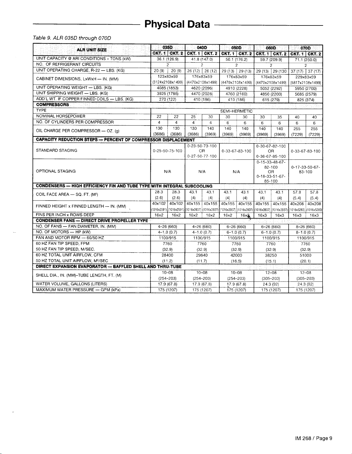
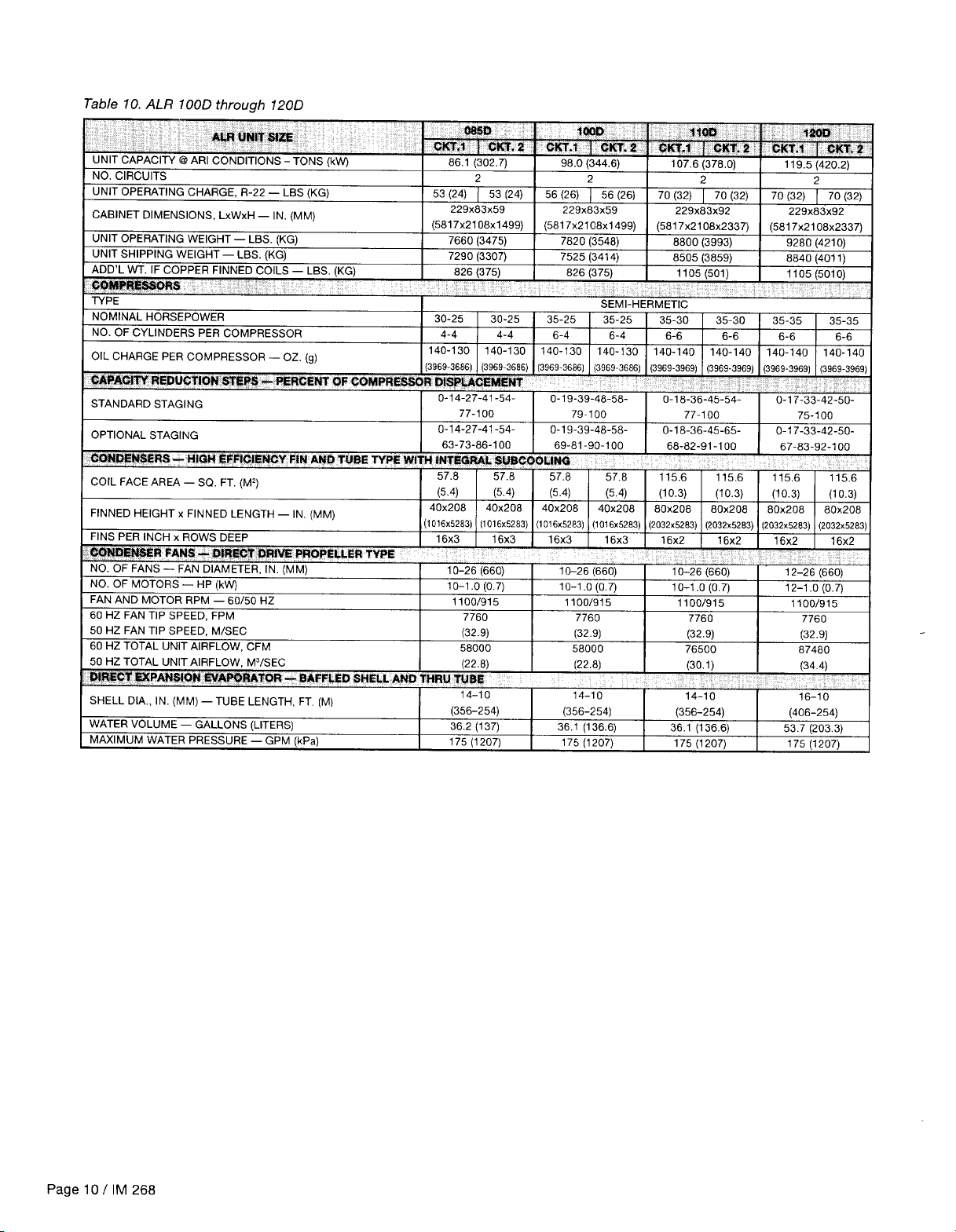
Physical Data
Major Components
Dimensional Data
...........................................................
.......
........................................................
........................................................
.........................................................
...............
..............................................................
......................................................
.....................................................
Field Wiring
ElectricalData Single Point
Electrical Data Multiple Point
VoltageLimitations
............................................
Compressor and Condenser Fan Motors
Customer Wiring
TypicalField Wiring
Information................................
Diagram.......................................
...................................
................................
.............
Unit Layout and Principles of Operation
Major Component
Locations.......................................
ControlCenter.......................................................
DisconnectLocation
Electrical
Legend
Sequence of Operation
....................................................
.........................................................
...............................................
Start-up and Shutdown
Pre Start-up.................................................................
Start-up........................................................................
Temporary Shutdown
Start-up After Temporary Shutdown..
Extended Shutdown
..................................................
.........................
....................................................
9-12
14-16
17-l 8
19-21
. ......
22-23
24-26
28-29
4, 5
7-8
8
13
21
27
28
29
30
31
32
32
32
32
33
3
System Maintenance
3
3
3
4
4
General.........................................................................
Fan
Motor Bearings
ElectricalTerminals..
Compressor Oil
Oil
Equalization
Condensers..
Refrigerant
Sightglass.................................................
.....................................................
....................................................
Level
............................................................
................................................................
Lead-Lag......................................................................
6
7
Service
7
7
Filter-Driers
LiquidLine Solenoid Valve
Thermostatic
Evaporator
..................................................................
Expansion Valve
...................................................................
In Warranty Return Material Procedure
Compressor
Components
.................................................................
Other Than
Appendix
Standard Controls
Thermostat
Control
Oil
Pressure Safety Control
High
Low
Compressor
..............................................................
Band
...........................................................
Pressure Control
Pressure Control
Lockout..............................................
Compressor Motor Protector
Pressure Control
FanTroll
Head
Optional Controls
Pressure Control
SpeedTroll
Head
High Ambient Control
High Return Water Control
Low Ambient Start
Freeze
Control
PartWinding
Phase/Voltage
Hot Gas Bypass
........................................................
Start...................................................
Monitor.....................................
......................................................
Controls,Settings and
Troubleshooting Chart
..................................................
..........................................
....................................
Compressors
......................
..............................37-38
............................................
.............................................
.................................
..............................
.........................
.............................................
.....................................
..................................................
41-42
Functions
.............................................
...........................43-44
45-46
33
33
33
33
33
34
34
34
34
34
35
35
36
36
37
37
38
38
38
38
39
40
40
41
41
41
41
42
Page 2 / IM 268
Product Warranty
...........................................................
See freeze protection references under the heading “Water Piping” on pages 6 and 13.
“FanTrol,” “McQuay.”
of McQuay International, Minneapolis, Minnesota, USA.
“Bulletin Illustrations cover the general appearance of McQuay International products at the time of
publication and we reserve the right to make changes in design and construction at anytime without notice.”
SeasonPak” and “SpeedTrol” are registered trademarks
“
46
Page 3

Introduction
General Description
McQuay type SeasonPak air cooled water chillers are complete, self-contained automatic refrigerating units that include the latest in engineered components arranged to
provide a compact and efficient unit. Each unit is completely
assembled and factory wired before evacuation, charging
and testing, and comes complete and ready for installation.
Each unit consists of twin air cooled condensers with integral
subcooler sections, multiple accessible hermetic compres-
sors, replaceable tube dual circuit shell-and-tube evaporator, and complete refrigerant piping. Liquid line components
that are included are manual liquid line shutoff valves, sightglass/moisture indicators, and double diaphragm hydraulic
element thermal expansion valves. Other features include
Nomenclature
Reciprocating Compressors
compressor crankcase heaters, an evaporator heater for
chilled water freeze protection, limited pumpdown during
“on” or “off” seasons, compressor lead-lag switch to alternate the compressor starting sequence, and sequenced
starting of compressors.
The electrical control center includes all safety and operating controls necessary for dependable automatic operation. Condenser fan motors are fused in all three conductor
legs and started by their own three-pole contactors. Compressors are not fused but may be protected by optional
circuit breakers, or
bythe
field installed fused disconnect for
protection.
Inspection
When the equipment is received all items should be carefully
checked against the bill of lading to insure a complete
shipment. All units should be carefully inspected for damage
upon arrival. All shipping damage must be reported to the
carrier and a claim must be filed with the carrier. The unit
serial plate should be checked before unloading the unit to
be sure that it agrees with the power supply available.
Physical damage to unit after acceptance is not the responsibility of
McQuay.
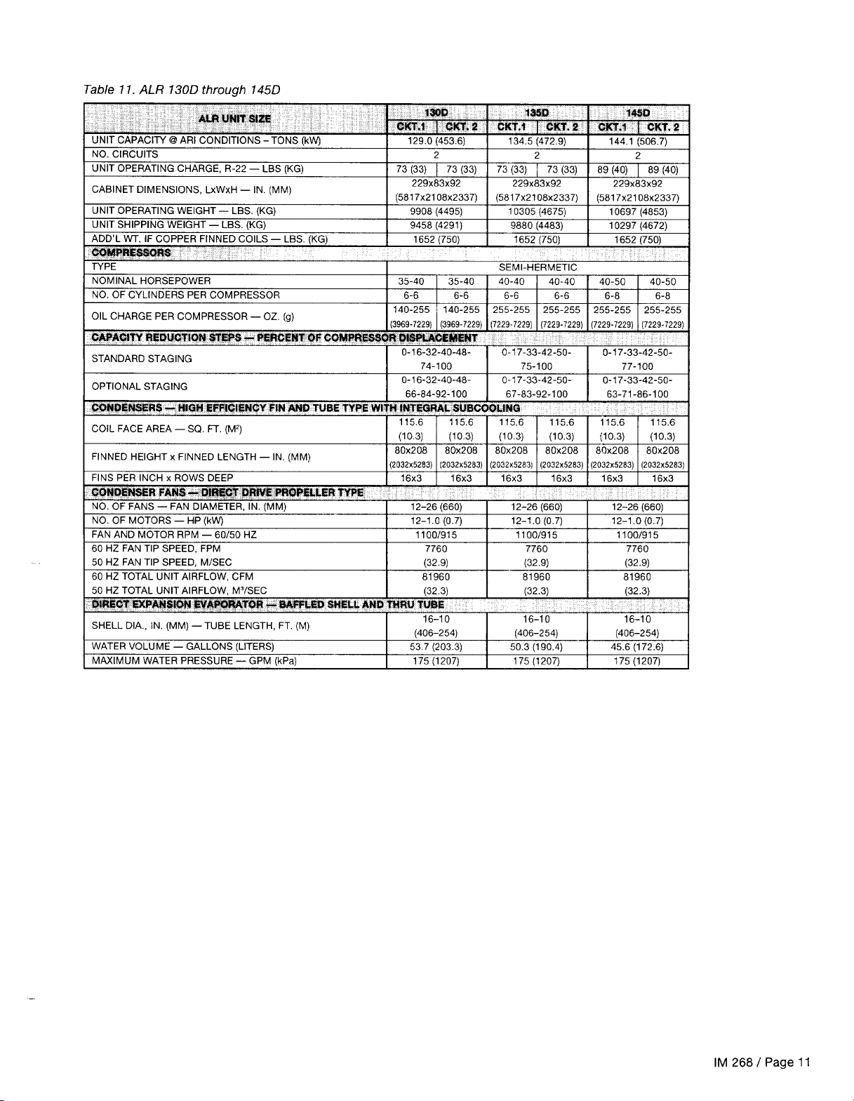
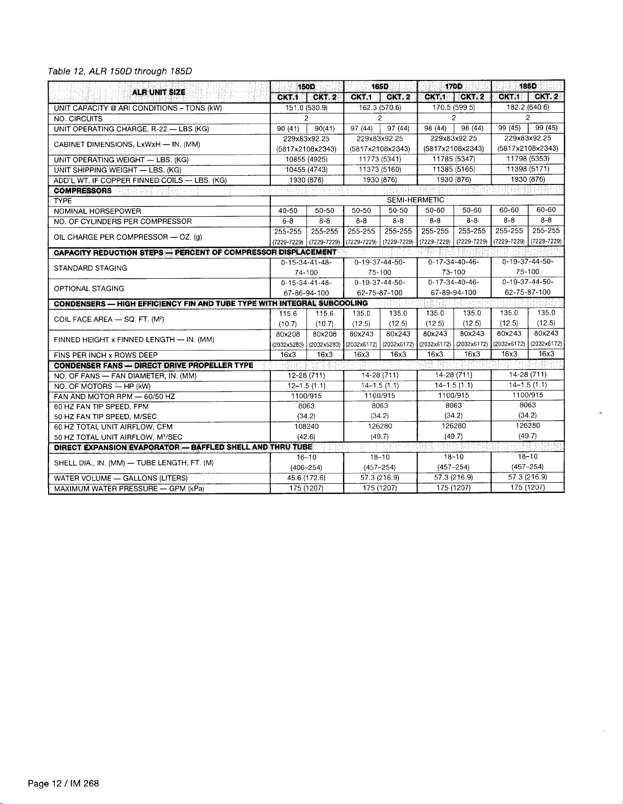
Note: Unit shipping and operating weights areavailable in
the Physical Data tables on pages 9 through 12.
Installation
Note: Installation and maintenance are to be performed
only by qualified personnel who are familiar with local
codes and regulations, and experienced with this type of
equipment.
.
Sharp edges and coil surfaces are a potential injury
hazard Avoid contact with them.
Handling
Care should be taken to avoid rough handling or shock due moving as this may result in serious damage.
to dropping the unit. Do not push or pull the unit from any- To lift the unit,
thing other than the base, and block the pushing vehicle
provided in the base of the unit. Spreader bars and cables
away from the unit to prevent damage to the sheet metal should be arranged to prevent damage to the condenser
cabinet and end frame (see Figure 1).
coils or unit cabinet (see Figure 2).
Never allow any part of the unit to fall during unloading or
Figure
1.
Suggested pushing arrangement
Blocklng Required
/-Across
Full Width
Figure 2. Suggested lifting arrangement
Spreader Bars
Recommended
(Use
CautIonI
2-1/2”
(64mm) diameter lifting holes are
Note: Number of fans can
vary from this diagram. but
lifting
method remains the
same.
(Note Control Box
LocatIon)
IM 268 / Page 3
Page 4

Location
Care should be taken in the location of the unit to provide
proper airflow to the condenser, minimizing effects on condensing pressure.
Due to the vertical condenser design of the ALR 110
through 185 chillers, it is recommended that the unit is
oriented to that prevailing winds blow parallel to the unit
lenght, thus minimizing the effects on condensing pressure.
If it is not practical to orient the unit in this manner, a wind
deflector should be constructed.
Minimizing clearances as shown in Figure 3 will prevent
most discharge air recirculation to the condenserwhich will
have a significant effect on unit performance.
Table 7. Clearances
Au? WJIT SIZE
035D -
070D
085D - 185D 10 ft. (3048mm) Min.
Notes:
1.
Minimum clearance between units is 1’2 ft.
2.
Units must not be installed in a pit that
3.
Minimum clearance on each side is 12 ft. (3658mm) when installed w a pit.
“X”
DHWENION
8
ft. (2438mm) Min.
(3658mm).
IS
deeper than the height of the
unit.
Service Access
Figure 3. Clearance requirements
;I-~-:_1
Each end of the unit must beaccessible after installation for assembly should be removed for service.
periodic service work. Compressors, filter-driers, and manual
liquid line shutoff valves are accessible on each side of the
to the
unit adjacent
control box. High pressure, low pressure,
The fan blade and fan motor rain shield must be removed
for access to wirinq terminals at the top of the motor.
and motor protector controls are on the compressor.
Freezestats and cooler barrel thermostats are nearthecooler.
Most other operational, safety and starting controls are
located in the unit control box.
On all ALR units the condenser fans and motors can be
removed from the top of the unit. A complete fan/motor
Disconnect all power to the unit while servicing con-
denser fan motors. Failure to do so may cause bodily
injury or death.
Vibration Isolators
Vibration isolators are recommended for all roof mounted
installations or wherever vibration transmission is a consideration. Table 2 lists spring isolators for all ALR unit sizes.
Figure4 shows isolator locations in relation to the unit control
center. Figure 5 gives dimensions that are required to secure
Table 2. Vibration isolators (spring) Table 3. Spring flex isolators
ICPl-31 (CPl-31 (CPl-31 /CPl-31 (CPi-31 (CPl-31
10
ID
1
CPl-321CPl-32
1
CPl-321CPl-321CPl -321CPI
-32
each McQuay isolator selection to the mounting surface.
Table 4 shows the isolator loads at each location in Figure 4,
and the maximum loads for each McQuay selection are
shown in Table 3.
L
Page 4
I IM
1300
135D
14!H3
?soD
1650
17Cm
1950
268
CPZ-28 CP2-28
CP2-31 CP2-31
CP2-31
CP2-32 CP2-32
CP2-31
CP2-32 CP2-32 CP2-32
CP2-31
CP2-32 CP4-27 CP2-32
CP2-32 CP2-32 CP4-27 CP2-32
CP4-27 CP2-32 CP2-32 CP4-27 CP2-32 CP2-32
CP4-27 CP2-32 CP2-32 CP4-27 CP2-32 CP2-32
CP4-27 CP2-32 CP2-32 CP4-27 CP2-32 CP2-32
CP2-31
CP2-32
CP2-28 CP2-28
CP2-31 CPZ-31 CP2-32
CP2-31
CP2-32 CP2-32
CP2-31
CP2-31
CPZ-32
CP2-31
J
Page 5

Page 6

Water Piping
Due to the variety of piping practices, it is advisable to follow
the recommendations of local authorities. They can supply
the installer with the proper building and safety codes re-
quired for a safe and proper installation.
Basically, the piping should be designed with a minimum
number of bends and changes in elevation to keep system
cost down and performance up. It should contain:
1.
Vibration eliminatorstoreducevibrationand noisetrans-
mission to the building.
2.
Shutoff valves to isolate the unit from the piping system
during unit servicing.
3.
Manual or automatic air vent valves at the high points of
the system. Drains should be placed at the lowest points
in the system.
Some means of maintaining adequate system water
4.
pressure (e.g., expansion tank or regulating valve).
Temperature and pressure indicators located at the unit
5.
to aid in unit servicing.
A strainer or some means of removing foreign matter
6.
from the water before it enters the pump. It should be
placed far enough upstream to prevent cavitation at the
pump inlet (consult pump manufacturer for recommendations). The use of a strainer will prolong pump life and
thus keep system performance up.
A strainer should also be placed in the water lines just
7.
prior to
the inlets of the evaporator and condenser. This
will aid in preventing foreign material from entering and
decreasing the performance of the evaporator.
8.
The shell-and-tube cooler has a thermostat and heating
cable to prevent feeze-up, due to low ambient, down to
-20°F (-29°C). It is suggested that the heating cable be
wired to a separate 11 OV supply circuit. As shipped from
the factory, it is factory wired to the control circuit. Any
water piping to the unit must also be protected to
prevent feezing.
9.
If the unit is used as a replacement chiller on a previously
existing piping system, the system should bethoroughly
flushed prior to unit installation and then regular water
analysis and chemical water treatment on the evaporator and condenser is recommended immediately at
equipment start-up.
10. The total quantity of water in the system should be
11. In the event glycol is added to the water system, as an
If a separate disconect is
the cooler heating cable, it should be clearly marked
so that it is not accidentally shut off during cold
seasons.
preliminary leak check should be made.
moisture condensationand possible damage to the building
structure. It is important to have the vapor barrier on the
outside of the insulation to prevent condensation within the
insulation on the cold surface of the pipe.
Figure 6. ALR evaporator
J
sufficient to prevent frequent “on-off” cycling. The total
quantity of water, in the system, turnover rate should not
be less than 15 minutes.
afterthought for freeze protection, recognize that the
refrigerant suction pressure will be lower, cooling performance less, and water side pressure drop is greater.
If the percentage of glycol is large, or if propylene is
employed instead of ethylene glycol, the added pressure drop and loss of performance could be substantial.
Reset the freezestat and low leaving water alarm temperatures. The freezestat is factory set to default at 36°F
(2.2%). Reset the freezestat setting to approximately
to 5°F (2.3” to 2.8%) below the leaving chilled water
setpoint temperature. See the section titled
“Glycol
Solutions” for additional information concerning glycol.
used for the
110V supply to
Prior to insulating the piping and filling the system, a
Piping insulation should include a vapor barrierto prevent
1
1L
T-
4”
III
Figure 7. Typical field evaporator water piping
Page 6 / IM 268
Pressure
Gauge
Vibration
Eliminator
Lf
Water
Strainer
Gate
Valve
awitch
Note: Chilled water piping should be insulated.
Balancing
Valve
Gate
Valve
Page 7

Flow
A water flow switch must be mounted in either the entering
or leaving water line to insure that there will be adequate
water flow and cooling load to the evaporator before the unit
can start. This will safeguard against slugging the compres-
sors on startup. It also serves to shut down the unit in the
event that water flow is interrupted to guard against evaporator freeze-up.
A flow switch is available from McQuay under ordering
number 00175033-00. It is a “paddle” type switch and
Switch
adaptable to any pipe size from 1” (25mm) to 6” (152mm)
nominal. Certain minimum flow rates are required to close
the switch and are listed in Table 6. Installation should be as
shown in Figure 8. Electrical connections in the unit control
center should be made at terminals 5 and 6. The normally
open contacts of the flow switch should be wired between
these two terminals. There is also a set of normally closed
contacts on the switch that could be used for an indicator
light or an alarm to indicate when a “no flow” condition exists.
Table 6. Flow switch minimum flow rates
2% ( 63.5)
3( 76.2) 30.00
4
(101.6)
5
(127.0)
6
(152.4)
Note: Water pressure differential switches are not recommended for outdoor
applications.
24.30 (1.50)
(1.90)
39.70
(2.50)
58.70
(3.70)
79.20
k5.00)
Water Connections
Water piping to thecooler can be brought up from the bottom
of the unit or through the side between the vertical supports.
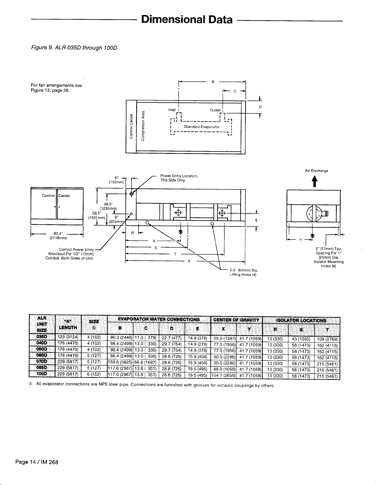
The dimensional data on pages 14 through 16 give the
necessary dimensions and locations for all piping connections.
Refrigerant Charge
All units are designed for use with Refrigerant 22 and are
shipped with an operating charge. The operating charge for
Figure 8.
L5’
(127mm)
Min.
After Switch
Note: On units sizes
Dia.
150D
through
L
5’ (127mm) Pipe Dia.
Min. Before Switch
185D
there is a
diagonal bracket off of a vertical support which will interfere with
the water connection if brought in from the side. This brace
can be removed, but only after the unit is in place.
each unit is shown in the Physical Data tables on pages 9
through 12.
Glycol Solutions
The system glycol capacity, glycol solution flow rate in gpm,
and pressure drop through the cooler may be calculated
using the following formulas and table.
Note: The procedure below does not specify the type of
glycol. Use thederatefactors found in Table 7 for corrections
when using ethylene glycol and those in Table 8 for propylene glycol.
1.
Capacity -Cooling capacity is reduced from that with
plain water. To find the reduced value multiply the chiller’s
water system tonnage by the capacity correction factor C
to find the chiller’s capacity in the glycol system.
2.
Flow -To determine evaporator gpm (or AT) knowing AT
(or gpm) and capacity:
Glycol
gpm =
24
x
capacity
For Metric Applications
(or AT) knowing AT (or Ips) and
Glycol Ips =
kW
4.18 x
(glycol)
AT
x G (from table)
-To determine evaporator Ips
kW:
x Flow (from table)
AT
Pressure drop
-To determine pressure drop through
the cooler, when using glycol, enter the water pressure
drop curve on page8 at the actual glycol gpm. Multiply the
water pressure drop found there by P to obtain corrected
glycol pressure drop.
To determine glycol system
kW
by factor K.
multiply the
water system
kW,
Test coolant with a clean, accurate glycol solution hy-
drometer (similar to that found in service stations) to deter-
mine the freezing point. Obtain percent glycol from the
freezing point table below. On glycol applications it is nor-
mally recommended by the supplier that a minimum of 25%
solution by weight be used for protection against corrosion.
Do not use an automative grade antifreeze. Industrial
grade glycols must be used. Automotive antifreeze
contains inhibitors which will cause plating on the
copper tubes within the chiller evaporator. The type
and handling of glycol used must be consistent with
local codes.
IM 268 / Page 7
Page 8

Page 9
Page 10
Page 11
Page 12
Page 13
Page 14
Page 15

Page 16

Page 17

Field
Wiring must comply with all applicable codes and ordinances. Warranty is voided if wiring is not in accordance with
specifications. An open fuse indicates a short, ground, or
overload. Before replacing a fuse or restarting a compressor
or fan motor, the trouble must be found and corrected.
Copper wire is required for all power lead terminations at
the unit while either aluminum or copper can be used for all
other wiring.
ALR units may be ordered with internal power wiring for
either single or multiple point power connection. If single
point power connection is ordered, a single large power
terminal block is provided and wiring within the unit is sized
in accordance with the National Electrical Code.
supplied disconnect is required. An optional
transformer may be performed.
If multiple point power wiring is ordered, three power
connections, one per compressor circuit plus one for con-
denser
fans and control circuit, are required and wiring within
the unit is sized in accordance with the National Electrical
Code. Separate field supplied disconnects are required for
each of the three circuits. A single power block is provided for
all of the condenser fans and the optional 115V control
transformer.
It may be desirable to have the unit cooler heater on a
separate disconnect switch from the main unit power supply
so that the unit may be shut down without defeating the
freeze protection provided by the cooler heater.
A single
field
factory mounted
Wiring
Internal power wiring to the compressors for the
single point versus the multiple point option are different. It is imperative that the proper field wiring be
installed according to the way the unit is built.
Canadian c-ETL listing
Canadian units which are c-ETL listed and are equipped for
multiple point power connections have a sticker (see figure
below) next to the wiring diagram in the control box. This
notifies the installer that local authorities may require the unit
to be connected to a single electrical power source. Check
with local authorities for requirements.
Although
be prowded with
optlons requiring more
than one source of
electrical supply. some
electrical
authorities may require
this unit to be
connected to a
external electrical
supply.
this umt
inspectlon
wngle
may
Table 14. Electrical data single point
03fiD
CWD
MOD
OS00
07QQ
085R
continued on next page
IM 268 / Page
17
Page 18

Page 19

Page 20

Page 21

Page 22

Page 23

Page 24

Page 25

Page 26

Page 27

Page 28

Page 29

Page 30

Page 31

Sequence of Operation
The following sequence of operation is typical for ALR
Season Pak air cooled water chiIler. Models ALR035D through
ALR 185D (items in italics apply only to Models ALR 0850
through
upon options.
185D).
The sequence vanes somewhat depending
Start-up
With the control circuit power on and the control stop switch
S1
closed,
fuse
HTR2
MP1
control circuit transformer. The 24V transformer provides
power to the contacts of the low pressure controls LP1 and
LP2 and the compressor lockout time delays
When the remote time clock or manual shutdown switch
turns on the chilled water pump, the flow switch closes and
115V
water control
response to the LWC1 provided the manual pumpdown
switches PS1 and PS2 are closed (in the “auto” position); the
compressor lockout time relays R5 and R6 (R7 and
thefreezestats FS1 and FS2, high pressurecontrols HP1 and
HP2, and the compressor motor protectors
(MP3 and MP4) do not sense failure conditions.
On a call for cooling, the leaving water control LCW1
energizes the liquid line solenoid valve SV1 for refrigerant
circuit
through the expansion valve and into the evaporator. As the
evaporator refrigerant pressure increases, the low pressure
115V
power is applied through the control circuit
F1
to the compressor crankcase heaters (HTR1 and
(HTR3
and
HTR4),
the compressor motor protections
and MP2
power is applied to the relay contacts on the leaving
#1,
(MP3
and
MP4
and the primary of the 24V
TD1
and TD2.
LWC1
The unit will automatically operate in
R8);
and
MP1
and MP2
opening the valve and allowing refrigerant to flow
control PL1 closes. This energizes the compressor starting
relay
R9,
starting the compressor via the compressor contactors Ml and
thecondenserfan motorcontacts
starting the fan motors.
As additional stages of cooling capacity are required, the
leaving water control LCW1 energizes the liquid line solenoid
valve SV2 of the refrigerant circuit
sequencing time delay
sequence is initiated in refrigerant circuit
If still more cooling is required, the leaving water control
will start
unloader solenoids until the capacity requirement is met.
M5.
Closing the R9 contacts also energizes
M11,
M12, Ml3 and M14,
#2.
TD11
has closed, the same starting
the
remaining compressors and then de-energize
After the compressor
#2.
Pumpdown
As the leaving water control is satisfied, it will unload the
compressor(s) and then de-energize the liquid line solenoid
valve(s)
compressor has pumped most of the refrigerant out of the
evaporator and into the condenser, the low pressure control(s)
PL1 and LP2 will open. If the refrigerant leaks into the low
side causing the pressure to close the low pressure controls
LP1 and LP2, the compressor will start after a two-hour time
delay to pump the refrigerant into the condenser coil. If there
is a call for cooling during the two-hour time delay, the timer
is bypassed and the compressor will start.
pumpdown cycle. Flow switch, time clock and ambient
lockout thermostat must be wired to allow pumpdown when
unit is turned off.
SV1
and SV2, causing
Note:
Do not shut the unit down without going through the
the valve(s)
to close. When the
IM 268 / Page 31
Page 32

Start-up and Shutdown
1.
With all electric disconnects open, check all screw or lug
type electric connections to be sure they are tight for
good electrical contact. Check all compressor valve
connections for tightness to avoid refrigerant loss at
start-up. Although all factory connections are tight before shipment, some loosening may have resulted from
shipping vibration.
2.
Inspect all water piping for flow direction and correct
connections at the evaporator.
Check to see that the thermostat water temperature
3.
sensor is installed in the leaving water line (supply to
building). On all ALR
factory mounted.
4.
Check the compressor oil level. Prior to start-up, the oil
level should cover at least one-third of the oil sightglass.
5.
Check the voltage of the unit power supply and see that
it is within the
voltage unbalance must be within
Check the unit power supply wiring for adequate am-
6.
pacity
and a minimum insulation temperature of 75°C.
Verifythat all mechanical and electrical inspections have
7.
been completed per local codes.
units the
*lo%
tolerance that is allowed. Phase
sensor well and sensor are
*2%.
Pre Start-up
See that all auxiliary control equipment is operatrve and
8.
that an adequate cooling load is available for initial start-
up.
Open the compressor suction and discharge shutoff
9.
valves until backseated. Always replace valve seal caps.
Making sure control stop switch
10.
pumpdown switches
pumpdown,” throw the main power and control disconnect switches to “on.” This will energize crankcase
heaters. Wait a minimum of 12 hours before starting up
unit.
11.
Open all water flow valves and start the chilled water
pump. Check all piping for leaks and vent theairfrom the
evaporator as well as from the system piping. Flush the
evaporator and system piping to obtain clean, noncorrosive water in the evaporator.
Most relays andterminals in the unit control center are
hot with Sl and the control circuit disconnect on. Do
not close
S1
until start-up.
S1
is open (off) and
PS1
and PS2 are on “manual
Start-up
1.
Double check that the compressor suction and discharge shutoff valves are backseated. Always replace
valve seal caps.
Open the oil equalization line valve
2.
185D
only).
3.
Open the manual liquid line shutoff valve at the outlet of
the subcooler.
4.
Adjust the dial on temperature controller LCW1 to the
desired chilled water temperature and set the control
band (see “Thermostat” on page 37).
Start the auxiliary equipment for the installation by
5.
turning on the time clock, ambient thermostat and/or
remote on/off switch, and chilled water pump.
Check to
6.
in the “manual pumpdown” (open) position. If pressures
on the low side of the system are above 60 psig (414
kPa),
Move pumpdown switches PSI and PS2 to the “manual
pumpdown” position. After the compressors have pumped
down, turn off the chilled water pump.
see that
the unit will start and pump down.
pumpdown switches PS1 and PS2 are
(ALR 085D
through
Temporary
10.
Shutdown
the water flow to the unit is interrupted to avoid freeze-up in
the evaporator.
7.
After the compressor lockout timer
start the system by moving the pumpdown switches
PS1 and PS2 to the “auto pumpdown” position.
8.
After running the unit for a short time, check the oil level
in each compressor crankcase, rotation of condenser
fans, and check for flashing in the refrigerant sightglass
(see “Maintenance” on page 34).
Superheat is factory adjusted to maintain between 8°F
9.
and 12°F
between 8°F and 12°F
After system performance has stabilized, it is necessary
that the “Compressorized Equipment Warranty Form”
(Form No.
ranty benefits. This form is shipped with the unit, and
after completion should be returned to McQuay Service
through your sales representative.
It is important that the compressors pumpd down before
(4.4”C
415415Y)
and
6.7”C).
Verify that the superheat is
(4.4X
be completed to obtain full war-
and
TD1
has timed out,
6.7X).
1.
Start the chilled water pump.
2. With emergency stop switch
pumpdown switches PS1 and PS2 to the “auto pumpdown” position.
3.
Observe the unit operation for a short time to be sure that
the compressors do not cut out on low oil pressure.
/
Page 32
IM 268
Start-up After Temporary Shutdown
S1
in the “on” position, move
If shutdown occurs or will continue through periods
below freezing ambient temperatures, make
sions to insure against chiller vessel freeze-up.
provi-
Page 33

Extended Shutdown
1.
Close the manual liquid line shutoff valves.
2. After the compressors have pumped down, turn off the
chilled water pump.
3.
Turn off all
4. Move the emergency stop switch
5. Close the compressor suction and discharge valves and
the oil equalization line valve.
power to
the unit and to the chilled water pump.
S1
to the “off” position.
System Maintenance
General
6. Tag all opened disconnect switches to warn against startup before the compressor suction and discharge valves.
7.
If glycol is not used in the system, drain all water from the
unit evaporator and chilled water piping if the unit is to be
shut down during winter. Do not leave the vessels or
piping open to the atmosphere over the shutdown
period.
On initial start-up and periodically during operation, it will be
necessary to perform certain routine service checks. Among
these are checking the compressor oil level and taking
condensing, suction and oil pressure readings. During the
operation, the oil level should be visible in the oil sightglass
with the compressor running. On units ordered with gauges,
condensing, suction and oil pressures can be read from the
vertical supports on each side of the unit adjacent to the
compressors.
Fan Motor Bearings
The fan shaft bearings are of the permanently lubricated type. No lubrication is required.
Excessive fan motor bearing noise is an indication of a potential bearing failure.
Electrical Terminals
Electric shock hazard. Turn off all power before con-
tinuing with following service.
Compressor Oil Level
The oil level should be watched carefully upon initial start-up
and for some time thereafter.
At the present time, Suniso No.
Texaco WF32 oils are approved by
compressors. The oil level should be maintained at about
one-third of the sightglass on the compressor body. Oil
levels may fluctuate between compressors in the same
refrigerant circuit on four-compressor units (ALR 085Dthrough
185D).
Oil may be added to the Copeland compressor through
the oil fill hole in the crankcase. To add oil, isolate the crank-
case and pour or pump in the necessary oil. If the system
contains no refrigerant, no special precautions are neces-
3GS,
Calumet R015, and
Copeland
for use in these
The gauges are factory installed with a manual shutoff
valve on each gauge line. The valves should be closed at all
times except when gauge readings are being taken. On units
ordered without gauges, Shrader fittings should be installed
in the plugged ports provided on the suction and discharge
King valves on each compressor circuit,
All power electrical terminals should be retightened every six
months, as they tend to loosen in service due to normal
heating and cooling of the wire.
sary other than keeping the oil clean and dry.
If the system contains a refrigerant charge, close the
suction valve and reduce crankcase pressure to
(6.9 to 13.8
charge valve.
Add the required amount of oil. During the period the
compressor is exposed to the atmosphere, the refrigerant
will generate a vapor pressure, retarding the entrance of
contaminants. Before resealing the compressor, purge the
crankcase by opening the suction valve slightly for
seconds. Close the oil port, open the compressor valves and
restore the system to operation.
kPa).
Stop the compressor and close the dis-
1
to 2 psig
1
or 2
Oil Equalization
Units with four compressors (ALR 085D through
equipped with oil equalization lines connecting the crankcases of both compressors in each refrigerant circuit. This
allows the oil to move from one compressor crankcase to the
other during normal operation, and balance between the two
when the compressors are off. This method of equalization
prohibits the oil level from dropping below the level of the
sightglass. Some difference in crankcase oil levels wills till
185D)
come
exist during unit operation.
The oil equalization line contains a manual shutoff valve
for isolating a compressor during service work. The ball
valves are shipped in the closed position with a tag attached
stating “Notice, Valve Shipped In Closed Position. Can Be
Open For Normal Operation.” When valves are closed for
compressor service, make sure they are opened again for
unit operation.
IM 268
/
Page 33
Page 34

Condensers
Condensers are air cooled and constructed with
O.D. internally finned copper tubes bonded in a staggered
pattern into slit aluminum fins. No maintenance is ordinarily
required except the occasional removal of dirt and debris
from the outside surface of the fins. McQuay recommends
the use of foaming coil cleaners available at air conditioning
7~”
(9.5mm)
Refrigerant Sightglass
The refrigerant sightglasses should be observed periodically.
(A monthly observation should be adequate.) A clear
glass of liquid indicates that there is adequate refrigerant
charge in the system to insure proper feed through the
expansion valve. Bubbling refrigerant in the sightglass indicates that the system is short of refrigerant charge. Refrigerant gas flashing in the sightglass could also indicate an
Lead-Lag
An optional feature on all McQuay ALR air cooled chillers is
a system for reversing the sequence in which the compressors start. (Chillers with the hot gas bypass option on only
one circuit do not have lead-lag.) For example, on a unit with
the lead-lag switches in the “circuit 1 leads” position, the
normal starting sequence is compressor
#1
then compres-
supply outlets. Use caution when applying such cleaners as
they may contain potentially harmful chemicals. Care should
be taken not to damage
of the purge valve on the condenser will prevent the buildup
of nonconcondensables. The purge valve is located under
the
#1
fan deck of each compressor circuit.
excessive pressure drop in the line, possibly due to a clogged
filter-drier or a restriction elsewhere in the system. An ele-
ment insidethe sightglass indicates what moisture condition
corresponds to a given element color. If the sightglass does
not indicate a dry condition after
the unit should be pumped down and the filter-driers changed.
#2.
With the lead-lag switches in the “circuit 2 leads”
sor
position, the reversed starting sequence is compressor
then compressor #1 . It is achieved electrically by a multipole
switching arrangement. It is suggested that the lead-lag
switches in the unit control center be switched annually to
provide even compressor life.
the
fins during cleaning. Periodic use
about
12 hours of operation,
#2,
Service
Service on this equipment is to be performed by
qualified refrigeration personnel familiar with equip- the unit.
ment operation, maintenance, correct servicing procedures, and the safety hazards inherent to this work.
Causes for repeated tripping of safety controls must
be investigated and corrected.
I
Filter-Driers
To change the filter-drier, pump the unit down by moving
pumpdown switches
position.
Move the control switch
all power to the unit and install jumpers across the terminals
shown in the table. This will jump out the low pressure
PS1
and PS2 to
the“manual
S1
to the “off” position. Turn off
pumpdown”
Disconnect all power before doing any service inside
I
I
requirements set forth by the EPA in regards to refrig-
controls. Close the manual liquid line shutoff valve(s). Turn
power to the unit back on and restart the unit by moving the
control switch S1 to the “on” position. The unit will start
pumping down past the low pressure setting. When the
evaporator pressures reaches 0 to 5 psig (0 to 34.5
move control switch S1 to the “off” position.
Frontseat the suction line King valve(s). Remove and
replace the filter-drier(s). Evacuate the lines through the
liauid line manual shutoff
that may have entered during filter replacement. Aleakcheck
is recommended before returning the unit to operation.
valve(s)
1
kPa),
to remove noncondensables
Liquid Line Solenoid Valve
The liquid line solenoid valves, which are responsible for
automatic pumpdown during normal unit operation, do not
normally require any maintenance. They may, however,
require replacement of the solenoid coil or of the entire valve
assembly.
The solenoid coil may be removed from the valve body
without opening the refrigerant piping by moving pumpdown
switches Ps1 and PS2 to the “manual pumpdown” position.
Page 34
/
IM 268
The coil can then be removed from the valve body by simply
removing a nut or snap-ring located at the top of the coil. The
coil can then be slipped off its mounting stud for replacement Be sure to replace the coil on its mounting stud before
returning pumpdown switches
pumpdown” position.
To replace the entire solenoid valve, follow the steps
involved when changing a filter-drier.
Ps1
and PS2 to the “auto
Page 35

Thermostatic
The expansion valve is responsible for allowing the proper
amount of refrigerant to enter the evaporator regardless of
cooling load. It does this by maintaining a constant superheat. (Superheat is the difference between refrigerant temperature as it leaves the evaporator and the saturation
temperature corresponding to the evaporator pressure.) All
ALR chillers are factory set for between 8°F and 12°F
(4.4%
to 6.7%) superheat. If it is necessary to increase the superheat setting of the valve, remove the cap at the bottom of the
valve to expose the adjustment screw. Turn the screw
clockwise (when viewed from the adjustment screw end) to
increase superheat and counterclockwise to reduce superheat. Allow time for system rebalance after each superheat
adjustment.
The expansion valve, like the solenoid valve, should not
normally require replacement, but if it does, the unit must be
pumped down by following the steps involved when changing a filter-drier.
If the problem can be traced to the power element only, it
can be unscrewed from the valve body without removing the
valve, but only after pumping the unit down.
Evaporator
The evaporator is of the direct expansion, shell-and-tube
type with refrigerant flowing through the tubes and water
flowing through the shell overthetubes. The tubes are internally finned to provide extended surface as well as turbulent
flow of refrigerant through the tubes. Normally no service
work is required on the evaporator. There may be instances
where a tube will leak refrigerant into the water side of the
system. In the cases where only one or two tubes leak, the
problem can best be solved by plugging the tube at both
ends. When the tube must be replaced, the old tube can be
removed and replaced.
To remove a tube, the unit should be temporarily pumped
down. Follow the steps involved when changing a filter-drier.
The tubes are mechanically expanded into the tube sheets
(see Figure 20) at each end of the cooler. In order to remove
the tubes, it is necessary to break this bond by collapsing the
tube. After doing this at both ends of the shell, the tube can
be removed for replacement. The new tube can then be
inserted and re-expanded into the tube sheet.
of typical dual circuit shell-and-tube evaporator
view
Liquid Connections
Expansion Valve
Figure 19. Thermostatic expansion valve
Power Element
(Contains Diaphragm)
-
Spring
Adjustment Screw
The bond produced by expansion must be refrigerant
tight. This bond must be
(red) to the tube and rolling it into the tube sheet.
After re-assembling the evaporator, a small amount of
refrigerant should be introduced by momentarily opening the
manual liquid line valve. A leak check should then be performed on the evaporator.
Tube removal can only take place after the leaking tube is
located. One method would be to subject each tube to air
pressure by plugging each end and, with a pressure gauge
attached to one of the end plugs, observing if there is a loss
of air pressure over a period of a minute or two.
Another method is to place a cork plug in each tube on
both ends of the cooler and applying pressure to the shell of
the cooler. After a period of time, the pressure will leak from
the shell into the leaking tube or tubes and pop out the cork
plug.
produced
by applying Locktite
Re
rlgerant lubes
Water Nozzles
IM 268 / Page 35
Page 36

In-Warranty Return Material Procedure
Compressor
Copeland Refrigeration Corporation has stocking wholesalers who maintain a stock of replacement compressors and
service parts to serve refrigeration contractors and service
personnel.
When a compressor fails in warranty, contact your local
sales representative, or Warranty Claims Department at the
address on the cover of this bulletin. You will be authorized
to exchange the defective compressor at a Copeland wholesaler, or an advance replacement can be obtained. A credit
is issued you by the wholesaler for the returned compressor
after Copeland factory inspection of the inoperative compressor. If that compressor is out of Copeland’s warranty a
salvage credit only is allowed. Provide full details;
Components Other Than Compressors
Material may not be returned except by permission of authorized factory service personnel at Minneapolis, Minnesota. A
“return goods” tag will be sent to be included with the
returned material. Enter the information as called for on the
tag in order to expedite handling at our factories and prompt
issuance of credits.
The return of the part does not constitute an order for
replacement. Therefore, a purchase order must be entered
through your nearest McQuay representative. The order
i.e,
unit
model and unit serial numbers. Include the invoice and the
salvage value credit memo copies and we will reimburse the
difference. In thistransaction, be certain
is definitely defective. If a compressor is received from the
field that tests satisfactorily, a service charge plus a transportation charge will be charged against its original credit
value.
On all out-of-warranty compressor failures, Copeland
offers the same field facilities for service and/or replacement
as described above. The credit issued by Copeland on the
returned compressor will be determined by the repair charge
established for the particular unit.
should include part name, part number, model number and
serial number of the unit involved.
Following our personal inspection of the returned part,
and if it is determined that the failure is due to faulty material
or workmanship, and in warranty, credit will be issued on
customer’s purchase order.
All parts shall be returned to the pre-designated factory,
transportation charges prepaid.
that the
compressor
Page 36
/
IM 268
Page 37

Appendix
Standard Controls
Perform an operation check on all unit safety controls
once per year.
Thermostat
The AS-UNT33n-1 microprocessor-based leaving water
control is designed to control multiple capacity steps of
cooling from a single sensor.
The device is provided with up to eight steps of capacity.
The
AS-UNT33n-1
setpoint and control band as shown in “Control Band” below.
If the Leaving Chilled Water Temperature begins to rise to the
desired setpoint plus control band /2 (upper limit), cooling
stage 1 makes bringing on the first stage of cooling. Additional stages of cooling will follow as long as the leaving water
temperature remains above the upper limit of the control
band. As the leaving water temperature begins to drop to
setpoint
will begin to de-energize.
stages as long as the leaving water temperature is between
the upper and lower limits of the control band.
the upper limit of the control band, stages will be energized,
and anytime the leaving water temperature falls below the
lower
is a 60 second interstage On Delay between stages. Each
stage incorporates minimum on and off timers with a maximum cycle rate of six cycles per hour.
scription of the control’s application, settings, adjustments,
and checkout procedures.
minus control band /2 (lower limit), cooling stages
There will be no energizing or de-energizing of cooling
As a rule, any time the leaving water temperature is above
limit of
At the initial start of the unit a time delay will occur. There
Note: Refer to bulletin IM 552 for a more complete de-
operation is based on an adjustable
the control band, stages will be de-energized.
Control band
Leaving Water Temperature will be controlled to the Actual
Leaving Water Setpoint. The Actual Leaving Water Setpoint
will be a function of what mode of operation the controller is
in and if a reset option is used. The Control Band potentiometer located on the front of the controller is used to determine
the Actual Leaving Dead Band and Prop Band.
Actual Leaving Dead Band: Control band
Actual Leaving Prop Band: Dead band * number of stages.
Example:
Control band = 4°F (2.2%)
=
2*6 =
12°F (6.7%)
6
Number of stages
Dead band = 4/2 =2”F (1 .1 “C)
Prop band =
As the Leaving Water Temperature rises above the Actual
Leaving Water Setpoint, but within the Leaving Dead Band,
there will be no Compressor Command (Staging). As the
Leaving Water Temperature continues to rise above the
Dead Band and into the Prop Band, the Compressor Command will be increased. When Leaving Integration Gain is
used, a Proportional Plus Integral command will be calculated. As the Compressor Command increases, stages of
cooling capacitywill be energized. Minimum on, off, interstage
timers, and cycles per hour attributes will control the stages.
As the Leaving Water Temperature decreases towards
(A16)/2.
Figure 27. AS-UNT33n-1 leaving water control algorithm
the Actual Leaving Water Setpoint, the Compressor Com-
mand will be decreased. Upon re-entering the Dead Band,
the current Compressor Command will be maintained. If the
Leaving Water Temperature falls below the Actual Leaving
Water
Command will again start to decrease.
The “Control Band” is the non-stage area
Anytime the Leaving Water Temperature is outside of the
Control Band limits, staging will occur. Anytime the Leaving
Water Temperature is within the Control Band limits, no
staging occurs. As shown in the figure below, with a 45°F
(7.2%)
stages of cooling energize when the Leaving Water is 47°F
(8.3%) or higher. Stages de-energize when the Leaving
Water is 43°F (6.1%) or lower
stages
and 47°F (8.3%).
Operation limits
Do not operate unit at a thermostat setting below 42°F (6°C)
or above 50°F (10%) as serious problems may result such as
cooler freeze-up or compressor overheating.
operation
Setpoint
will
(using the same Dead Band),
setpoint and a 4°F (2.2%) Control Band setting,
[4”F
remain in
their
current state between 43°F (6.1 “C)
(2.2%) difference]. All
the Compressor
of the
controller.
Oil pressure safety control
The oil pressure safety control is a manually resettable
device which senses the differential between oil pressure at
the discharge of the compressor oil pump and suction
pressure inside the compressor crankcase. When the oil
pressure reaches approximately 15 psig (103
crankcase suction pressure, the pressure actuated contact
of the control opens from its normally closed position. If this
pressure differential cannot be developed, the contact will
remain closed and energize a heater element within the
control. The heater element warms a normally closed bimetallic contact and causes the contact to open, de-energizing
a safety relay and breaking power to the compressor.
It takes about 120 seconds to warm the heater element
enough to open the bimetallic contact, thus allowing time for
the pressure differential to develop.
If during operation, the differential drops below 10 psig
kPa)
above the
IM 268
/
Page 37
Page 38

(69
kPa),
the heater element will be energized and the
compressor will stop. The control can be reset by pushing
the reset button on the control. If the compressor does not
restart, all a few minutes for the heater elements and bime-
tallic contacts to cool and reset the control again.
To
check the
the unit. Open thecircuit breakers
control, pumpdown and shut off all
or the
fused disconnect for
power to
that compressor and install a voltmeter between terminals L
and M of the oil pressure control. Turn on power to the unit
control circuit (separate disconnect or main unit disconnect
depending on the type of installation). Check to see that the
control stop switch
S1
is the “on” position. The control circuit
should not be energized, but with the absence of compressor
power, no oil pressure differential can develop and thus the
pressure actuated contacts of the control will energize the
heater element and open the bimetallic contacts of the
control within 120 seconds. When this happens, the safety
relay is de-energized, the voltmeter reading will rise to
115V,
and the compressor contactor should open. Repeated operations of the control will cause a slight heat buildup in the
bimetallic contacts resulting in a slightly longer time for reset
with each successive operation.
Figure 22. Oil pressure safety control
Pressure Actuator
contact
T2
Line
Note
2
Bimetallic Contacts
Notes: 1. Hot only when unit thermostat calls for compressor to run.
2. Hot only when other safety control contacts are closed.
L M
Heater Element
I
Safety
Neutral
Relay
High pressure control
The high pressure control is a single pole pressure activated
switch that closes on a pressure rise. When the switch
closes, R1 is energized which in turn de-energizes the
control circuit, shutting down thecompressor circuit.
R1
also
locks itself in a manually resettable holding circuit through
RS1
. The switch is factory set to close at 400 psig (2759
and open at 300 psig (2069
kPa).
kPa)
To check the control, either block off condenser surface
or start the unit with condenser fan motor fuses in only one
fan fuse block (FB6) and observe the cutout point of the
control on a high pressure gauge
The control is attached to a Shrader fitting and is located
on a cylinder head near the discharge King valve.
Aftertesting the high pressure control, check the pressure
relief device (on the condenser header) for leaks.
Although there is an additional pressure relief device
in the system set at 450 psig (3104
recommended that the “control stop” switch
kPa),
it is highly
S1
be
close at hand in case the high pressure control should
malfunction.
Low pressure control
The low pressure control is a single pole pressure switch that
closes on a pressure rise. It senses evaporator pressure and
is factory set to close at 60 psig (414
open at 35 psig (241
running),
move the pumpdown switch(es)
kPa).
To check the control (unit must be
“manual pumpdown” position. As the compressor pumps
down, the evaporator pressure will drop. The lowest evapo-
kPa)
and automatically
PSI and PS2 to the
rator pressure reached before cutout is the cutout setting of
the control. Wait for the compressor lockout time delay(s)
TD1
and TD2 to timeout. By moving the
PS1 and
PS2
to the “auto pumpdown” position, evaporator
pumpdown
switch(es)
pressure will rise. The highest evaporator pressure reached
before compressor restart is the cutin setting of the control.
The control is attached to a Shrader fitting and is located
below the suction King valve body.
Compressor lockout
Compressor lockout consists of a fixed 5-minute time delay.
It is wired in series with the
R5
relay starting the compressor.
Its purpose is to prevent rapid compressor cycling when
cooling demands are erratic. The circuit illustrated in Figure
23 is for the compressor circuit
circuit
for
compressor circuit #2 is wired the same way. When
#1
control circuit. The control
the unit thermostat no longer calls for cooling and the
compressor contactor have opened, the lockout time
delay breaks open the circuit, preventing compressor restart.
The circuit remains open for a period of five minutes so
that, if the unit thermostat should call for cooling before the
delay period has expired, the compressor will not restart.
After five minutes the time delay will close its contacts to
complete the circuit to
compressor. When
will shunt around
R5,
energizing R9 and starting the
R9
is energized, another set of contacts
TD1
to reset open for timing out the next
compressor cycle.
To check the control, the compressor must be running
initially. Move the pumpdown switch
PS1
or PS2 to the
“manual pumpdown” position. The compressor should not
restartforfive minutes. Each refrigerant circuit can bechecked
the same way.
Figure 23. Compressor lockout
L1lle
Linee
Neutral
Line
i
“i”l
FE
I
I I
I I
I
F
I39
i
1 o
@
Ml
T
Neutral
_ Neutral
Compressor motor protector
The solid-state compressor motor protector module incor-
porates atwo-minute “time off” relay utilizing the bleed down
capacitor principle. Any time the protection system opens or
power to
delay is triggered, and the module will not reset for two
minutes. Once the two-minute period is passed, the motor
protector contacts 1 and 2 reset, provided the protection
system is satisfied and power is applied to the module.
period is passed, the pilot circuit will reset without delay
when power is reapplied.
Figure 24. Compressor motor protector
24V
1
1 SV Line
the module is interrupted, the two-minute “time off”
Note: If the power circuit is broken once the two-minute
Line
-----‘I
rl
2
Control
Relay
I
Neutral
‘age 38 / IM 268
Page 39

Fan Trol head pressure control
FanTrol is a method of head pressurecontrol which
cally
cycles the condenser fans in response to condenser
pressure and ambient air temperature. This maintains head
pressureand allows the unit to run at low ambient
atures.
All ALR units have dual independent circuits with the fans
for circuit 1 and circuit 2 being controlled independently by
Table 19. Factory FanTrol settings
automati-
air temper-
the condensing pressure and ambient air of each circuit.
Fans 11 and 21 start with each compressor and fans 12 and
22 cycle on and off in response to condenser pressure. The
cutout and cutin pressures are given in Table 19. Fans 13 and
14 (circuit 1) and fans 23 and 24 (circuit 2) are controlled by
ambient temperature and are factory set at the values given
in the table. Note that the number of fans on each unit varies.
FanTrol sensor locations are shown in Figures 25 through 28.
Notes:
0
With SpeedTrol all unit minimum ambient operating temperature drops to 0°F (18°C)
0
Minimum head pressure on partly loaded compressor is 110 psig (759
kPa);
on full load it is 170 psig (1172
kPa).
SpeedTrol and FanTrol will provide reasonable operating refrigerant discharge pressures to the ambient temperatures listed
for them provided the coil is not affected by the existence of wind. If wind may occur, and the unit includes vertical
condenser coils, it is the responsibility of the system designer or installer to make other provisions for low ambient control.
Consideration should be given to deflecting awnings, dampers, or a floodback receiver system as required to satisfy specific
job conditions.
IM 268
/
Page 39
Page 40

Optional Controls
SpeedTrol head pressure control
(optional)
The SpeedTrol system of head pressure control operates in
conjunction with FanTrol by modulating the motor speed on
fans 11 and 21 in response to condensing temperature. By
reducing the speed of the last fan as the condensing pressure falls, the unit can operate at lower ambient tempera-
tures.
The SpeedTrol fan motor is a single phase,
thermally protected motor specially designed for variable
speed application. The solid-state speed controls SC1 1 and
SC21 are mounted inside condenser fan 11 and 31 fan
compartment. Units with 460 volt power have a transformer
mounted inside the condenser fan 21 fan compartment to
step the voltage down to 230 volts for the SpeedTrol motor,
shown in Figures 26 and 28.
The SpeedTrol control
at approximately 230 psig (1586
starts to
modulatethe
kPa)
and maintains a mini-
Figure 25.
208/240
volt,
motor speed
mum condensing pressure of 170 to 180 psig (1172 to 1241
kPa).
The SpeedTroI sensors are clipped to a return bend on the
bottom row of the condenser coil.
High ambient control (optional)
The high ambient control is a single pole, pressure activated
switch that closes on a pressure rise to partially unload one
or both circuits. It senses condenser pressure and is factory
set to close at 375 psig (2586
reset at 300 psig (2069
block off condenser surface or start the unit with condenser
fan motor fuses in only fan fuse block (FB6) and observe the
cutin point of the control by monitoring when the compressor
unloads. The purpose of the control is to allow the unit to
continue operating when the ambient temperature exceeds
the design temperatures of unit. High ambient sensor locations are shown in Figures 25 and 27.
Figure 26.
SpeedTw
Controls
kPa)
and will automatically
kPa).
To check the control either
High Ambient
%?llSCVS
PC6 a
Figure 27.
PCS
FanTrol Sensors
PC22 a PC12
Figure 28.
FanTrol
TC13. TC14.
Sens ors
TC23,
SpeedTrol Controls
TC24
Page 40 I IM 268
Page 41

High return water control (optional)
The high return water control senses the temperature of
return water and partially unloads one or both compressor
circuits. The control has an adjustable 0 to 100°F (17.8 to
37.8%) temperature range with 3°F (1.7%) switch differen-
tial.
The purpose of the control is to prevent high superheated
suction temperatures entering the compressor should the
return water temperature become too high. High suction
temperature with the compressor at full load could result in
serious damage to the compressor. A 70°F (21
.l”C) setpoint
is recommended for the high return water thermostat.
The unit is shipped from the factory with the control
sensor taped to the bottom of the control box and must be
field installed. It is recommended that the sensor be clamped
to the side of the return water line
near the cooler connection
and insulated (see Figure 6).
To check the control, the system should be operating at
full load conditions. By slowly turning the dial setting down,
the control should partially unload one compressor circuit.
By continuing to dial the setting down, the second compressor circuit should unload depending on what the interstage
differential is set at.
Low ambient start (optional)
Low ambient start is available on all units as an option with
FanTrol
and included automatically with optional
It consists of a solid-state, normally closed time delay wired
in series with a relay. These are both wired in parallel to the
liquid line solenoid valve so that when the solenoid valve is
energized by the unit thermostat the low ambient start relay
is also energized through the time delay. The relay has con-
tacts that essentially short circuit the low pressure control
and freezestat and allow the compressorto start with the low
pressure control open.
After about 2-3/4 minutes, the time delay will open and de-
energize the relay. If the system has not built up enough
evaporator pressure to close the low pressure control, the
compressor will stop. The time delay can be reset to its
original normally closed position by moving the pumpdown
switch(es) PSI or PS2 to the “manual pumpdown” position.
Moving the pumpdown switch back to the “auto pumpdown”
position will again energize the relay for another attempt at
start-up. If the system has built up enough evaporator
pressure, the compressor will continue to run.
To check the control, turn off all power to the unit and
remove the wire(s) leading to the terminals of the low pressure control(s)
LP1
and LP2 and the freezestat FS1 and
FS2. Remove power to the compressor and jumper across
terminals 48 to 50 for circuit 1 and 78 to 80 for circuit 2.
Switch the pumpdown switch(es) PS1 and PS2 to the “auto
pumpdown” position. Energize the control circuit by turning
on the control circuit disconnect or main power disconnect
(depending on the installation) and the control stop switch
S1
The compressor contactors should pull in instantly and
trip back out after the 2%minute time delay.
Figure 29. Low ambient start
Low Ambient
Start Time Delay
Line
Note: Line is only hot when the unit thermostat calls for compressor to run.
TD9
Low Ambient
start Relay
SpeedTrol.
Neutral
T
Freeze control (optional)
The freeze control is a single pole pressure switch that closes
on a pressure fall. It contains a pressure actuated contact
that, upon a fall in evaporator pressure, energizes a
60-
second time delay. Aftertiming out, R1 is energized which in
turn de-energizes the 24V control circuit, shutting down the
compressor circuit. R1 also locks itself into a manually resettable holding circuit through
to close at 54 psig (372
The
60-second
time delay prevents nuisance cutouts due to
RS1
The control is factory set
kPa)
and open at 57 psig (393
kPa).
momentary drops in suction pressure.
To check the setpoint of the freezestat, attach one lead of
the voltmeter to terminal 46 in the control box and the other
lead to ground to check circuit
a suction
pressure above 57 (393 kPa), there should
#1.
With the unit running and
be 0 VAC
to ground. To check the cutin point of the freezestat, slowly
close off the manual liquid line shutoff valve bringing the
suction pressure down. When the freezestat switch closes,
slowly close off the manual liquid line shutoff valve bringing
the suction pressure down. When the freezestat switch
closes, the voltmeter will read 24V to ground. The corresponding pressure will be the cutin point of the control.
Slowly open the manual liquid line valve to check the cutout
point pressure of the control. To check the calibration of the
freezestat for compressor circuit
#2,
attach the voltmeter
between terminal 76 and ground and repeat the same steps.
To adjust the control if necessary, remove the setpoint
locking bracket from the top of the control. Unscrew the
pressure connection off the Shrader fitting on the suction
line. Attach the pressure connection to a refrigerant tank
through a set of compound gauges and slowly pressurize the
switch while listening for the cutin and cutout points of
control.
Turn theadjusting stem clockwise in%-turn increments to
decrease the cutin pressure of the control and counterclockwise to increase the cutin pressure of the control. After the
control is calibrated, reconnect the pressure connection to
the Shraderfitting on the suction line and reattach the locking
bracket to the top of the control.
Part winding start (optional)
Part winding start is available on all voltage units and consists of a solid-state time delay wired in series with the
contactor that energizes the second winding of each compressor motor. Its purpose is to limit current inrush to the
compressors upon start-up. As each compressor starts, the
contactor of the first motor winding is delayed for 1 second.
Control checkout is best accomplished by observation as
each contactor is pulled in to see that the 1 second delay
occurs before the second contactor pulls in.
Figure 30. Part winding start
Compr. Contactor
#1
Motor
Winding)
Line
I
TD1
A
Part Winding
Time Delay
Compr. Contactor
(#2
Motor
Windlng)
Phase/voltage monitor (optional)
The phase/voltage monitor is a device which provides protection against three-phase electrical motor loss due to
power failure conditions, phase loss, and phase reversal.
Whenever any of these conditions occur, an output relay is
deactivated, disconnecting power to the thermostatic con-
IM 268 / Page 41
Page 42

trol circuit, automatically pumping down the unit.
The output relay remains deactivated until power line
conditions return to an acceptable level. Trip and reset
delays have been provided to prevent nuisance tripping due
to rapid power fluctuations.
When three-phase power has been applied, the output
relay should close and the “run light” should come on. If the
output does not close, perform the following tests:
Check the voltages between
L1-L2, L1
-L3
and
L2-L3.
These voltages should be approximately equal and within
+lO%
of the rated three-phase line-to-line voltage.
If these voltages are extremely low or widely unbalanced
check the power system to determine the cause of the
problem.
If the voltages are good, turn off the power and interchange any two of the supply power leads at the disconnect.
This may be necessary as the phase/voltage monitor is
sensitive to phase reversal. Turn on the power. The output
relay should not close after the appropriate delay.
Hot gas bypass (optional)
Hot gas bypass is a system for maintaining evaporator pressure at or above a minimum value. The purpose for doing this
is to keep the velocity of the refrigerant as it passes through
the evaporator high enough for proper oil return to the compressor when cooling load conditions are light. It also maintains continuous operation of the chiller at light load conditions.
The system consists of a solenoid valve piped in series
with a pressure regulating valve as shown in Figure 31. The
solenoid valve is factory wired to open whenever the unit
thermostat calls for the first stage of cooling. The pressure
regulating valve is factory set to begin opening at 58 psig
(400
kPa) 132°F
(0°C) for R-221 when the air charged bulb is
in an 80°F (26°C) ambient temperature. Since the bulb is
factory mounted on the suction line, and suction line temperatures are usually in the 50°F to 60°F (10°C to 60°C)
range, Figure 32 indicates that for ALR chillers, the valve is
factory set to begin opening at 54 to 56 psig (372 to 386
kPa).
This setting can be changed by changing the pressure of the
air charge in the adjustable bulb. To raise the pressure
setting, remove the cap on the bulb and turn the adjustment
screw clockwise. To lower the setting, turn the screw coun-
Do
terclockwise.
not force the adjustment beyond the range
it is designed for, as this will damage the adjustment assembly.
The regulating valve opening point can be determined by
slowly reducing the system load (or increasing the required
chilled water temperature setting indicated on the unit thermostat) while observing the suction pressure. When the bypass valve starts to open, the refrigerant line on the evaporator side of the valve will begin to feel warm to the touch.
The gas line may become hot enough to cause injury
in a very short time; care should be taken during
valve checkout.
Figure 31. Hot gas bypass diagram
Figure 32. Hot gas bypass adjustment range
Solenoid Valve
Bypas Valve
stable Remote Bulb
External Equalizer Connection
To Suction Side of Evaporator
To Evaporator Inlet
After
Expansion
Valve
Page 42
I
IM 268
Page 43

Controls, Settings and Functions
(Texas
Instruments)
Oil Pressure
High Ambient Unloader
Pressure Control
FanTrol Condenser
Pressure Control
Pumpdown
Control
Switch
Phase/Voltage Monitor
Reset Switches
Control Stop Switch
Lead-Lag Switches
I
1
Protects the evaporator from water freeze-up.
Time delay prevents nuisance trips. TD15, 16
Stops compressor when discharge pressure is too
high.
(Used for pumpdown) Stops compressor when suction LPI, 2
pressure is too low.
Protects motor from high temperature by sensing
winding temperature.
Stops compressor if oil pressure drops below setpolnt
for 120 seconds.
Unloads compressor circuits if condenser pressure is
too high.
Maintains condenser pressure by cycling the condenser fans in response to ambient air temperature
(TC) and condenser pressure (PC). TC23, 24, 25
Used to manually pump down compressor circuit.
Protects motor from power failure, phase loss and
phase reversal.
Restarts compressor circuit if it cuts out on
pressure or freezestat.
Shuts down entire control circuit.
Reverses sequence that compressors start in.
FUNCTION
high
1 SYMBOL ]
1
FS1,
2
HP1,
2
MP1-4
OP1-4
PC5. 6
PC1 2,22
TC13,14,15
PSI. 2
PVM
RS1 -4
S1
S2-4
!!
Closes
Opens at 57 psig (393
60 second
Closes at 400 psig (2759
Opens at 300 psig (2069
Closes at 60 psig (414
Opens at 35 psig (241
500 ohms cold to 20,000
ohms hot
Pressure sensor opens at 15
psig (103
drops below 10 psig (69
the sensor closes, energizing a
120 second delay before stop-
ping the compressor.
Closes at 375 psig (2586
Opens at 300 psig (2069
See table with
Auto/manual
-
N/A
N/A
On/off
-
1
Circuit1 leads Circuit
SETTING
at 54 psig (372
kPa)
oil pressure
FanTrol
2 or
kPa)
kPa)
kPa)
kPa)
kPa)
kPa)
kPa)
kPa)
kPa)
settings.
Manual thru
N/A
Manual thru
Auto
Auto from 2700-4500 ohms Compressor junction box
Manual
Auto
Auto
N/A
When conditions return to
an acceptable level.
Manual
N/A
N/A
N/A
RS1,
2
RS1,
2
RESET’
LOCATION
Suction line near cooler
Control box
On compressor
On compressor
On condenser coil header 75 psig (517
PC1 2-22 on coil header See table with
TC13-25 in control box settings
Sensors mounted in back
of control box
Control box
Control box
Control box
Control box
Control box
Back of control box or on N/A
bulkhead
DIFFERENTIAL
3 psig (21
N/A
100 psig (690
30 psig (207
15,000 ohms
N/A
N/A
N/A
N/A
N/A
kPa),
fixed.
kPa),
kPa),
kPa)
FanTrol
fixed
fixed
N/A
N/A
N/A
N/A
Condenser section on liquid N/A
line after filter-drier and be-
fore TEV.
Condenser section
Control box. Sensor in
supply water line to buildingfrom 0°F to 10°F
from chiller.
Control box
On cooler
Control box
N/A
Adjustable control band
(-12.2%)
Adjustable thru LWC1
N/A
3°F
(1.7”C),
fixed
I
Continued on next page
(-17.8”C
Page 44

The McQuay ALR SeasonPak air cooled water chiller provides not only lower operating costs, but
lower installation costs, low maintenance costs and greater design flexibility, in both comfort and
process cooling applications.
In order for McQuay to better serve our customers, feedback of recurring service problems or
complaints dealt with in the field would be appreciated. Problems or complaints can be reported to
McQuay by filling out a Product Quality Report (Form No.
2S-636-784). These forms are available
from McQuay Service and sales representative organizations and should be routed back through
these organizations to McQuay’s Engineering and Marketing departments.
Page 45

Troubleshooting Chart
Compressor will 1
1. Main switch
2. Fuse blown. Circuit breakers open.
3. Thermal overloads tripped.
4. Defective contactor or
5. System shut down by safety devices
6. No cooling required.
7. Liquid line solenoid will not open.
8. Motor electrical trouble.
9. Loose wiring.
1. Flooding of refrigerant into crankcase.
2. Improper piping support on suction or liquid line.
3. Worn compressor.
1. Noncondensables in system.
2. System overcharged with refrigerant.
3. Discharge shutoff valve partially closed.
4.
FanTrol
5. Fan not running.
6. Dirty condenser coil.
1. Faulty condenser temperature regulation.
2. Suction shutoff valve partially closed.
3. Insufficient refrigerant in system.
4. Low suction pressure.
5. Compressor operating unloaded.
1. Excessive load.
2. Expansion valve overfeeding.
3. Compressor unloaders open.
1. Lack of refrigerant.
2. Evaporator dirty.
3. Clogged liquid line filter-drier.
4. Clogged suction line or compressor suction gas strainers.
5. Expansion valve malfunctioning.
6. Condensing temperature too low.
7. Compressor will not unload.
8. Insufficient water flow.
9. Evaporator head ring gasket slippage.
3.
out of adjustment.
Faulty thermostat stage or broken wire.
coil.
1.
Close switch
2 Checkelectricalcircurtsand motorwtndingforshortsorgrounds
Investigate for possible overloading. Replace fuse or reset
breakers after fault is corrected. Check for loose or corroded
connections.
3 Overloads are auto reset. Check unit closely when unit comes
back on line.
4. Repair or replace.
5. Determine type and cause of shutdown and correct it before
resetting safety switch.
6. None. Wait until unit calls for cooling.
7. Repair or replace coil.
8. Check motor for opens, short
9 Check all wire
1.
Check setting of expansion valve.
2 Relocate, add or remove hangers.
3 Replace.
1 Purgee the noncondensables.
2. Remove excess.
3. Open valve.
4. Adjust
5.
Check electrical circuit.
6 Clean coil.
1 Check condenser control operation.
2. Open valve.
3. Check for leaks. Repair and add charge.
4. See
corrective steps for low suction pressure below.
5. See corrective steps for failure of compressor to load.
1. Reduce load or add additional equipment.
2. Check remote bulb. Regulate superheat.
3. See corrective steps for failure of compressor to load
1 Check for leaks. Repair and add charge.
2 Clean chemically.
3 Replace.
4 Clean
5 Check and reset for proper superheat.
6 Check means for regulating condensing temperature.
7 See corrective steps for failure of compressor to unload.
8 Adjust flow
9 To troubleshoot take pressure drop across vessel and consult
factory to obtain design pressure drop for that vessel.
1 Replace.
2 Replace.
3 Replace.
4
Reset thermostat setting to fit application.
1.
Replace
2 Adjust flow.
FanTrol
strainers.
junctions.
settings.
circuit
Tighten all terminal screws.
or burnout.
1.
Clogged suction oil strainer.
2. Excessive liquid in crankcase.
3. Oil pressure gauge defective.
4. Low oil pressure safety switch defective
5. Worn oil pump.
6. Oil pump reversing gear stuck in wrong position
7. Worn bearings.
8. Low oil level.
into crankcase.
2. Excessive compression ring blow-by
3. Suction superheat too high.
4. Crankcase heater burnout.
1.
Clean.
2. Check crankcase heater. Reset expansion valve tor
superheat. Check liquid line solenoid valve operation.
3. Repair or replace. Keep valve closed except when taking
ing.
4 Replace.
5. Replace.
6. Reverse direction of compressor rotation.
7 Replace compressor.
8
Add oil.
9 Check and tighten system.
10. Replace gasket.
11 Adjust thermal expansion valve.
12 Adjust flow.
13 Open valve.
1.
Check for leaks and repair. Add refrigerant
2 Replace compressor.
3. Adjust superheat.
4. Replace crankcase heater.
continued on next page
Page 45 / IM 268
higher
read-
Page 46

Thermal Protector
Switch Open
6. High ambient temperature around the overload relay.
7. Failure of second starter to pull in on part winding start system.
1.
Operating beyond design conditions
2. Discharge valve partially shut.
3. Blown valve plate gasket.
Product Warranty
1.
Check supply voltage for excessive line drop.
2. Replace compressor motor.
3.
Check all connections and tighten.
4.
See corrective steps for high discharge pressure.
5. Check supply voltage. Notify power company. Do not start
until fault is corrected.
6.
Provide ventilation to reduce heat.
7.
Repair or replace starter or time delay mechanism.
1. Add facilities so that conditions are within allowable limits
2. Open valve.
3. Replace gasket.
McQuay International, hereinafter referred to as the “Company,” warrants that it will provide, at the Company’s op-
tion, either free replacement parts or free repair of compo-
nent parts in the event any product manufactured by the
Company and used in the United States proves defective in
material or workmanship within twelve (12) months from initial start-up or eighteen (18) months from the date shipped
by the Company, whichever comes first. For additional consideration, McQuay warrants that for four (4) years following
the initial warranty period it will provide, at the Company’s
option, free replacement parts for the motor compressor, or,
free replacement for any integral component of the motorcompressor which proves defective in material or workmanship. For an additional consideration, McQuay warrants that
for nine (9) years following the initial warranty period it will
provide free replacement of the heat exchanger in gas-fired
or oil-fired furnaces which proves defective in material and
workmanship. (Extended warranties for motor-compressors
and heat exchangers are not applicable unless separately
purchased.)
To obtain assistance under this parts warranty, or extended motor-compressor warranty, simply contact the selling agency. For McQuay, BarryBlower and
JennFan
brand
names, contact McQuay International, Warranty Claims Department, PO. Box 1551, Minneapolis, MN 55440, telephone
(612) 553-5330.
This warranty constitutes the buyer’s sole remedy. It is
given in lieu of all other warranties. There is no implied war-
ranty of merchantability or fitness for a particular purpose.
In no event and under no circumstances shall the Company
be liable for incidental or consequential damages, whether
the theory be breach of this or any other warranty, negli-
gence or strict tort.
This parts warranty and the optional .extended warranties extend only to the original user. Of course, abuse, misuse, or alteration of the product in any manner voids the
Company’s warranty obligation. Neitherthe parts or extended
warranty obligates the Company to pay any labor or service
costs for removing or replacing parts, or any shipping
charges. Refrigerants, fluids, oils, and expendable items such
as filters are not covered by this warranty.
The extended warranties apply only to integral components of the motor-compressor or heat exchanger, not to
refrigerant controls, electrical controls, or mechanical controls, or to failures caused by failure of those controls.
Attached to this warranty is a requirement for equipment
containing motor-compressors and/or furnaces to report
start-up information. The registration form accompanying
the product must be completed and returned to the Company within ten (10) days of original equipment start-up. If
that is not done, the date of shipment shall be presumed to
be that is not done, the date of shipment shall be presumed
to be the date of start-up and the warranty shall expire twelve
(12) months from that date.
No person (including any agent, salesman, dealer or dis-
tributor) has authority to expand the Company’s obligation
beyond the terms of this express warranty, or to state that
the performance of the product is other than that published
by the Company.
Page 46
/
IM 268
 Loading...