

Page 1
Installation, Operation and Maintenance Manual IOMM ALR2
Packaged Air-Cooled Water Chiller
Models ALR 020E Through ALR 030E
60 Hertz
Group: Chiller
Part Number: 629951
Effective: June 1999
Supersedes: IM 688
© 1997 McQuay International
Page 2

Table of Contents
Introduction.........................................3
General Description................................................3
Inspection................................................................3
Installation...............................................................3
Handling..................................................................3
Location...................................................................4
Service Access........................................................5
Vibration Isolators..................................................6
Water Piping............................................................6
Flow Switch.............................................................8
Water Connections................................................9
Refrigerant Charge.................................................9
Glycol Solutions.....................................................9
Evaporator Water Flow and Pressure Drop........9
Unit Layout and Operation...............11
Control Center .......................................................11
Start-up and Shutdown......................11
Pre Start-up............................................................11
Start-up..................................................................11
Sequence of Operation........................................12
Electrical Data..................................14
Field Wiring...........................................................14
Dimensional Data.............................18
System Maintenance........................18
General...................................................................18
Fan Motor Bearings.............................................18
Electrical Terminals...............................................18
Condensers ...........................................................18
Refrigerant Sightglass.........................................19
Service...............................................19
Thermostatic Expansion Valve...........................19
Filter-Driers............................................................19
Liquid Line Solenoid............................................20
Standard Controls ................................................20
Compressor Lockout............................................22
Optional Controls .................................................23
Control Settings....................................................26
Troubleshooting Chart........................................27
Physical Data....................................13
"McQuay" is a registered trademark of McQuay International
"Illustrations cover the general appearance of McQuay International products at the time of publication and we reserve the right to make changes in
design and construction at anytime without notice"
1997 McQuay International
2 ALR 020E through 030E IOMM ALR2
Page 3
Introduction
General Description
McQuay air-cooled water chillers are complete, self-contained automatic refrigerating units. Every
unit is completely assembled, factory wired, charged, and tested. Each unit consists of two air-cooled
condensers connected in parallel with integral subcooler sections, Copeland DISCUS semi-hermetic
compressor, single circuit brazed plate-to-plate evaporator, and complete refrigerant piping. Liquid
line components include manual liquid line shutoff valve, sight-glass/moisture indicator, solenoid
valve, and double diaphragm hydraulic element thermal expansion valve. Other features include a
compressor crankcase heater, an evaporator heater for chilled water freeze protection, and a hot gas
muffler.
The electrical control center includes all safety and operating controls necessary for dependable
automatic operation. Condenser fan motors are three phase (except single phase on No. 1 fan with
FanTrol option) and started by their own contactors and have inherent overload protection. The
compressor is not fused but has solid state motor protection for inherent thermal overload protection.
Inspection
Check all items carefully against the bill of lading. Inspect all units for damage upon arrival. Report
shipping damage and file a claim with the carrier. Check the unit name plate before unloading, making
certain it agrees with the power supply available. Units are shipped fob factory and McQuay is not
responsible for physical damage after unit leaves the factory.
Note: Unit shipping and operating weights are listed on page 13, Table 3.
Installation
Note: Installation is to be performed by qualified personnel who are familiar with local codes
and regulations especially concerning refrigerant release to the atmosphere.
WARNING
Sharp edges and coil surfaces are a potential hazard. Avoid contact with them.
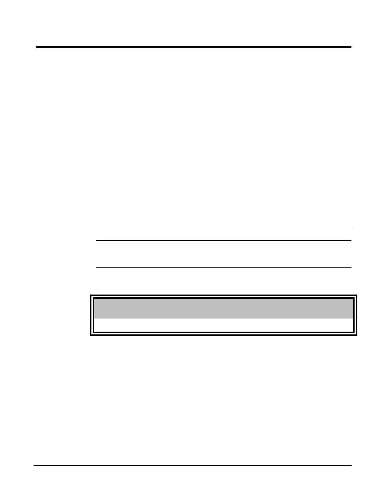
Handling
Be careful to avoid rough handling of the unit. Do not push or pull the unit from anything other than
the base. Block the pushing vehicle away from the unit to prevent damage to the sheet metal cabinet
and end frame (see Figure 1).
To lift the unit, lifting slots are provided in the base of the unit. Arrange spreader bars and cables to
prevent damage to the condenser coils or cabinet (see Figure 2).
IOMM ALR2 ALR 020E through 030E 3
Page 4
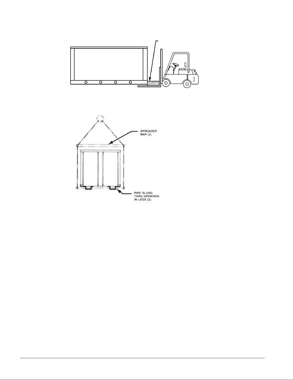
Figure 1, Suggested pushing arrangement
Figure 2, Suggested lifting arrangement
Blocking required
across full width
Location
Unit Placement
ALR units are for outdoor applications and can be mounted on a roof or ground level. Set units on a
solid and level foundation. For roof mounted applications, install the unit on a steel channel or I-beam
frame to support the unit above the roof. For ground level applications, install the unit on a
substantial base that will not settle. A one-piece concrete slab with footings extended below the frost
line is recommended. Be sure the foundation is level (within 1/2” [13 mm] over its length and width).
The foundation must support the operating weights listed in the Physical Data Table on page 13.
Unit operation is affected by wind and it should located so that length is parallel with the prevailing
wind. If this is not practical, field fabricated wind deflectors should be employed.
Clearances
The flow of air to and from the condenser coil must not be limited. Restricting airflow or allowing air
recirculation will result in a decrease in unit performance and efficiency. There must be no obstruction
above the unit that would deflect discharge air downward where it could be recirculated back to the
inlet of the condenser coil. The condenser fans are propeller type and will not operate with ductwork
on the fan outlet.
4 ALR 020E through 030E IOMM ALR2
Page 5
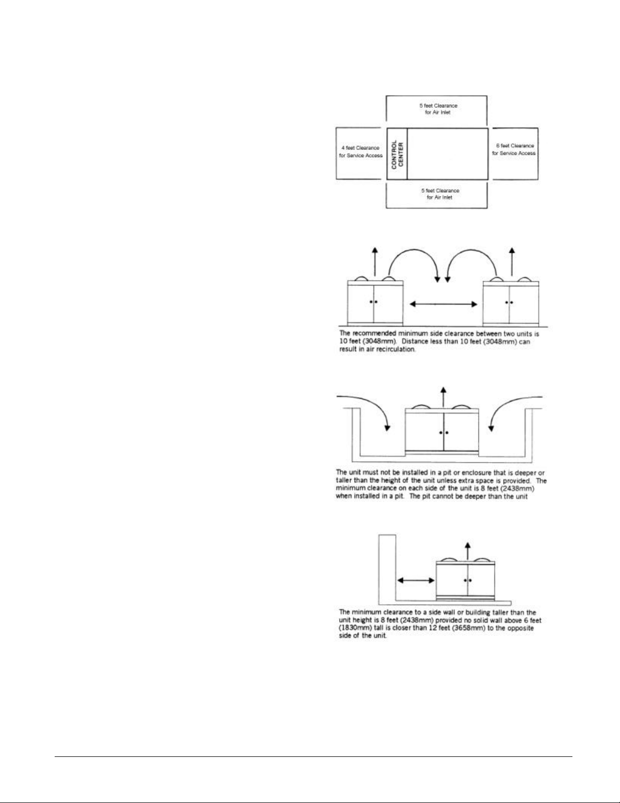
Install the unit with enough side
clearance for air entrance to the coil and
for servicing. Provide service access to
the evaporator, compressors, electrical
control panel and piping components
as shown in Figure 3. Do not block
access to the unit with piping or
conduit.
Do not allow debris to accumulate near
the unit. Air movement may draw
debris into the condenser coil causing
air starvation. Give special
consideration to low ambient operation
where snow can accumulate. Keep
condenser coils and fan discharge free
of snow or other obstructions to permit
adequate airflow.
Sound Isolation
The low sound levels of the ALR chiller
are suitable for most applications.
When additional sound reduction is
necessary, locate the unit away from
sound sensitive areas. Avoid locations
beneath windows or between
structures where normal operating
sounds may be objectionable. Reduce
structurally transmitted sound by
isolating water lines, electrical conduit
and the unit itself. Use wall sleeves
and rubber isolated piping hangers to
reduce transmission of water or pump
noise into occupied spaces. Use
flexible electrical conduit to isolate
sound through electrical conduit.
Spring isolators are effective in
reducing the low amplitude sound
generated by the Discus semi-hermetic
compressors and for unit isolation in
sound sensitive areas.
Figure 3, Clearance requirements
Service Access
Each end of the unit must be accessible
after installation for periodic service.
Compressors, filter-driers, and manual
liquid line shutoff valves are accessible
from the end of the unit. High pressure,
low pressure, and motor protector controls are on the compressor. Most operational, safety and
starting controls are located in the unit control box.
The condenser fan and motors can be removed from the top of the unit.
IOMM ALR2 ALR 020E through 030E 5
Page 6
Vibration Isolators
Vibration isolators are recommended for all roof mounted installations or wherever vibration
transmission is a consideration. The isolators can be purchased from McQuay by the part numbers
shown in the table. Install spring isolators under the main unit support according to the dimension
drawing. Adjust springs to allow the upper housing to clear the lower housing by 1/4” to 1/2”. An
anti-skid pad should be used if hold-down bolts are not used.
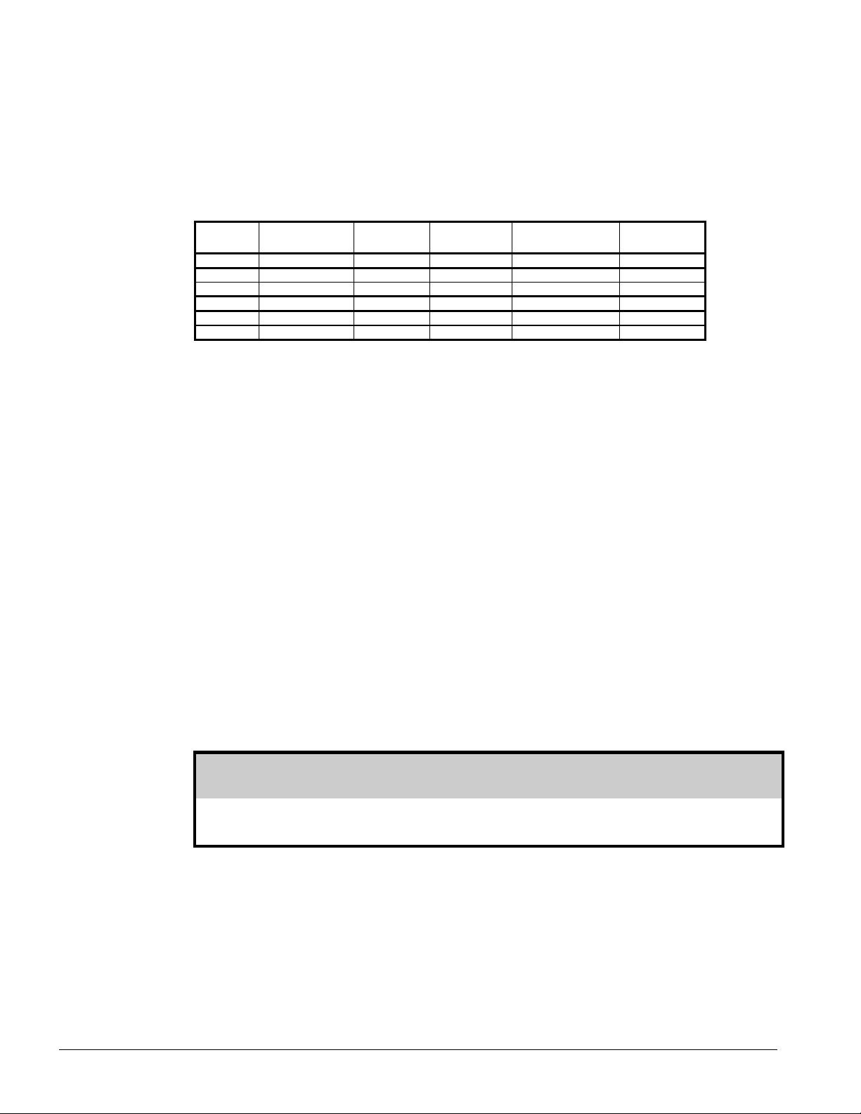
Table 1, Recommended Vibration Isolators
ALR UNIT ISOLATOR
TYPE
020E-028E Rubber-in-shear 00-216397-01 4 RP-3 Red 525
030E Rubber-in-shear 00-216397-01 2 RP-3 Red 525
020E-028E Spring Isolators 00-477927-26 4 CP-1-26 600
030E Spring Isolators 00-477927-26 2 CP-1-26 600
Note: See dimension drawing for location of isolators
McQUAY
PART NO.
00-216397-03 2 RP-3 Green 725
00-447927-27 2 CP-1-27 750
NUMBER
REQUIRED
ISOLATOR
DESCRIPTION
MAX. LOAD
EACH (LBS)
Water Piping
Local authorities can supply the installer with the proper building and safety codes required for safe
and proper installation.
Install piping with minimum bends and changes in elevation to minimize pressure drop. Consider the
following when installing water piping:
1. Vibration eliminators to reduce vibration and noise transmission to the building.
2. Shutoff valves to isolate the unit from the piping system during unit servicing.
3. Manual or automatic air vent valves at the high points of the system. Install drains at the lowest
points in the system.
4. A means of maintaining adequate system water pressure (expansion tank or regulating valve).
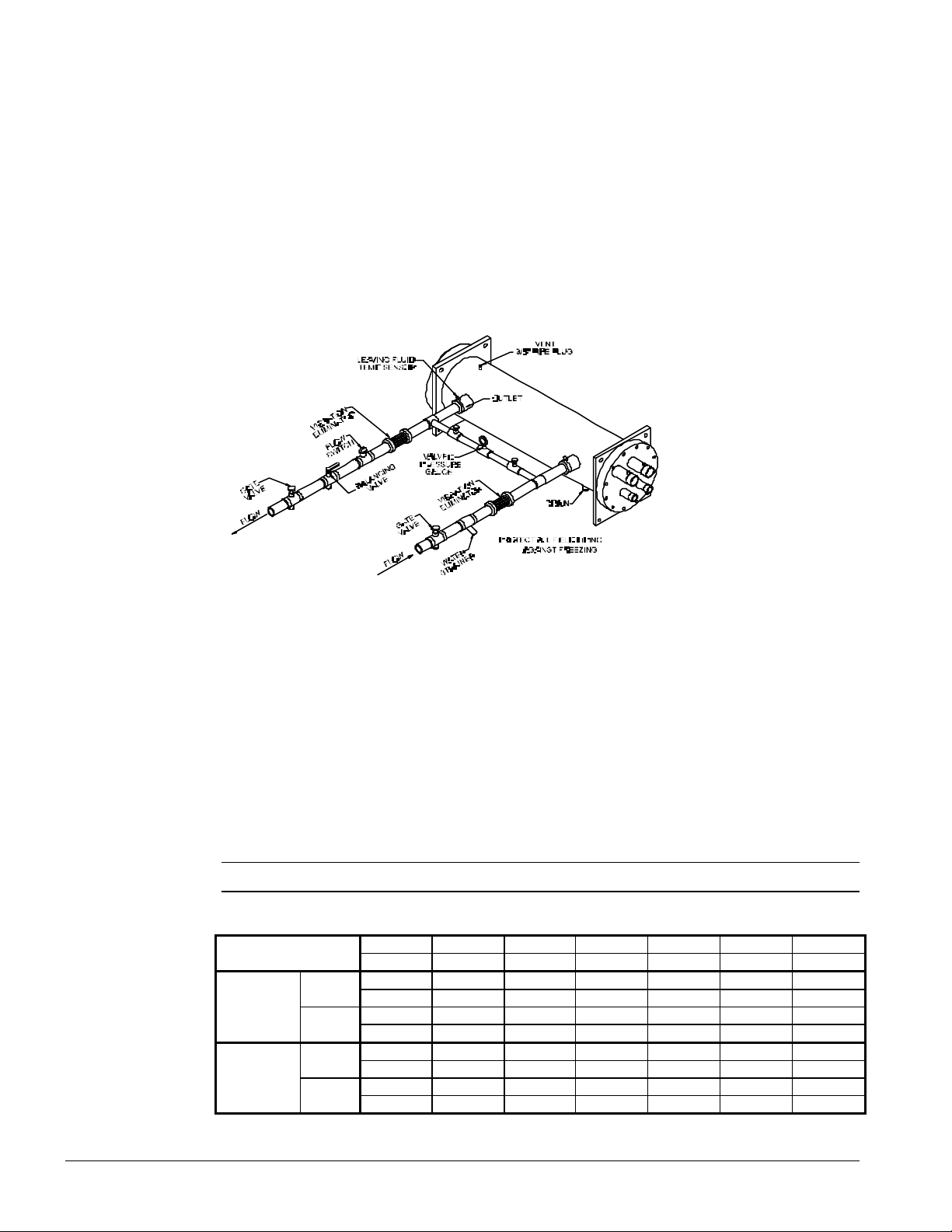
5. Temperature and pressure indicators located at the unit to aid in unit servicing. Pressure gauge
taps must be installed in the chilled water inlet and outlet piping or as shown in Figure 4.
6. A strainer or other means of removing foreign matter from the water before it enters the pump.
Place the strainer far enough upstream to prevent cavitation at the pump inlet (consult pump
manufacturer for recommendations). The use of a strainer will prolong pump life and keep system
performance up.
7. Place a strainer in the water line just before the inlet of the evaporator. This will help prevent
foreign material from entering and decreasing the performance of the evaporator.
CAUTION
If separate disconnect is used for the 110V supply to the evaporator heating cable, mark the
disconnect clearly to ensure disconnect is not accidentally shut off during cold seasons.
8. The brazed plate evaporator has a thermostat and heating cable to prevent freeze-up down to 20°F (-29°C). It is suggested that the heating cable be wired to a separate 110V supply circuit. As
shipped from the factory, the heating cable is wired to the control circuit. All water piping to the
unit must also be protected to prevent freezing.
9. If the unit is used as a replacement chiller on a previously existing piping system, flush the
system thoroughly before unit installation. Regular water analysis and chemical water treatment
on the evaporator is recommended immediately at equipment start-up.
6 ALR 020E through 030E IOMM ALR2
Page 7

10. The total water volume in the system should be sufficient to prevent frequent “on-off” cycling.
Turnover rate should not be less than 15 minutes for normal variable cooling loads. Turnover
rate for a constant load should not be less than 6 minutes.
IOMM ALR2 ALR 020E through 030E 7
Page 8
11. When glycol is added to the water system for freeze protection, the refrigerant suction pressure
will be lower, cooling performance less, and water side pressure drop greater. If the percentage of
glycol is high, or if propylene is used instead of ethylene glycol, the added pressure drop and
loss of performance could be substantial. Reset the freezestat and low leaving water alarm
temperatures. The freezestat is factory set to default at 36°F (2.2°C). Reset the freezestat setting
to approximately 4 to 5 degrees F (2.3 to 2.8 degrees C) below the leaving chilled water setpoint
temperature. See the section titled “Glycol Solutions” for additional information concerning
glycol.
12. Perform a preliminary leak check before insulating the piping and filling the system.
13. Piping insulation should include a vapor barrier to prevent condensation and possible damage to
the building structure.
Figure 4, Typical Field Evaporator Water Piping
Note: the above piping is correct for both brazed plate and tube-in-shell evaporators
Flow Switch
Mount a water flow switch in the leaving water line to shut down the unit when water flow is
interrupted.
A flow switch is available from McQuay (part number 0701804-04). It is a “paddle” type switch and
adaptable to pipe sizes down to 1 1/4 ” (32mm) nominal. Certain minimum flow rates are required to
close the switch and are listed in Table 2. Installation should be as shown in Figure 5. Connect the
normally open contacts of the flow switch in the unit control center at terminals 4 and 5. There is also
a set of normally closed contacts on the switch that can be used for an indicator light or an alarm to
indicate when a “no flow” condition exists. Freeze protect any flow switch that is installed outdoors.
NOTE: Differential pressure switches are not recommended for outdoor installation.
Table 2, Flow Switch Settings
mm 32 38 51 63 76 102Pipe Size
inch 1 1/4 1 1/2 2 2 1/2 3 4
gpm 4.8 6.3 9.9 15.3 24.4 33.3Flow
Minimum
Adjustment
Maximum
Adjustment
No
Flow
No
Flow
Lpm 18.2 22.7 37.5 57.9 92.4 126.0
gpm 3.0 3.6 5.9 9.5 15.4 21.1
Lpm 11.3 13.6 22.3 36.0 58.3 79.9
gpm 7.7 10.0 15.8 23.7 35.5 61.4Flow
Lpm 29.1 37.9 59.8 89.7 134.4 232.4
gpm 5.9 7.0 11.0 17.0 29.2 37.7
Lpm 22.3 26.5 41.6 64.3 110.5 142.7
8 ALR 020E through 030E IOMM ALR2
Page 9
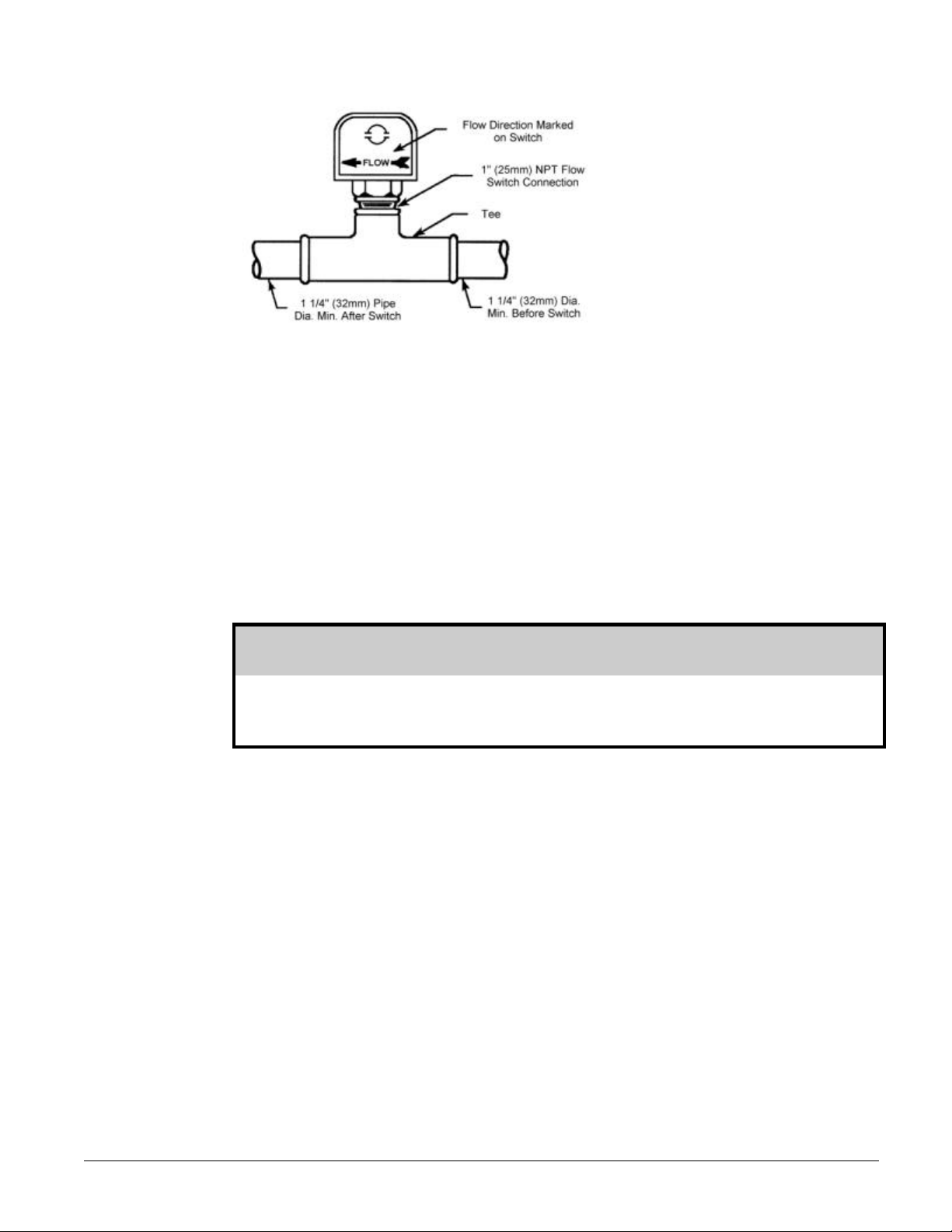
Figure 5, Flow Switch Installation
Water Connections
Bring water piping to the cooler from the end of the unit, in the top and out the bottom connection.
Refrigerant Charge
All units are designed for use with HCFC-22 and other refrigerants. See nameplate for specific
refrigerant used. Units are shipped with an operating charge. The operating charge
(using HCFC-22) for each unit is shown in the Physical Data Table on page 12.
Glycol Solutions
The use of glycol anti-freeze solutions will decrease unit capacity, and increase the pressure drop
through the cooler. See Product Manual 985 for specific ratings and correction factors.
CAUTION
Do not use automotive grade antifreeze. Industrial grade glycols must be used. Automotive
antifreeze contains inhibitors that will cause plating on the copper tubes within the chiller
evaporator. The type and handling of glycol used must be consistent with local codes.
Evaporator Water Flow and Pressure Drop
Evaporator flow rate must fall between the minimum and maximum values shown in the evaporator
pressure drop curve, Figure 6. Flow rates below the minimum values will result in laminar flow that will
reduce efficiency, cause erratic operation of the expansion valve and could cause low temperature
cutouts. Flow rates exceeding the maximum values can cause erosion on the evaporator water
connections and tubes.
Measure the chilled water pressure drop through the evaporator at field installed pressure taps. It is
important not to include the effect of valves or strainers in these readings.
Varying chilled water flow through the evaporator while the compressor are operating is not
recommended.
IOMM ALR2 ALR 020E through 030E 9
Page 10

Figure 6, Evaporator Water Pressure Drop Curve
10 ALR 020E through 030E IOMM ALR2
Page 11

Unit Layout and Operation
Control Center
All electrical controls are enclosed in a weatherproof control center with keylocked, hinged access
doors. The control center has two separate compartments, high voltage and low voltage. All high
voltage components are located in the compartment on the right side of the unit.
The low voltage components are located on the left side with the live terminals behind the deadfront
panel. This protects service personnel from live terminals when accessing the adjustable and
resettable controls.
Start-up and Shutdown
Pre Start-up
1. Open all electric disconnects and check all electric connections for tightness. Check all
compressor valve connections for tightness.
2. Inspect all water piping for flow direction and correct connections at the evaporator.
3. Verify thermostat water temperature sensor is installed in the leaving water line (supply to
building). On all ALR units the sensor well and sensor are factory mounted.
4. Check compressor oil level. The oil level should be visible in the oil sightglass.
5. Check voltage of the unit power supply and make certain voltage is within ±10% of nameplate
rating. Check unit power supply wiring for proper ampacity and a minimum insulation
temperature of 75°C.
6. Verify all mechanical and electrical inspections have been completed according to local codes.
7. Open compressor suction and discharge shutoff valves until backseated. Always replace valve
seal caps.
8. Open control stop switch S1(off). Turn on the main power and control disconnect switches. This
will energize crankcase heaters. Wait at least 24 hours before starting up unit.
9. Open all water flow valves and start the chilled water pump. Check all piping for leaks and vent
the air from the evaporator as well as from the system piping. Flush the evaporator and system
piping to obtain clean, noncorrosive water in the evaporator.
CAUTION
Most relays and terminals in the unit control center are energized with S1 and the control
circuit disconnect on. Do not close S1 until start-up.
Start-up
1. Verify compressor suction and discharge shutoff valves are backseated. Always replace valve
seal caps.
2. Open manual liquid line shutoff valve at the outlet of the condenser subcooler.
3. Set temperature controller CP1 to the desired chilled water temperature. Set the control band.
4. Start auxiliary equipment by turning on the following: time clock (if present), ambient thermostat
and/or remote on/off switch, chilled water pump.
IOMM ALR2 ALR 020E through 030E 11
Page 12

5. If the controller calls for cooling, the unit will begin the start-up sequence.
6. After running the unit for a short time, check the oil level in the compressor crankcase, rotation of
fans, and flashing in refrigerant sightglass.
7. Verify superheat temperature is at the factory setting of 8 to 12 degrees F (4.4 to 6.7 degrees C).
8. After system performance has stabilized, complete the “Compressorized Equipment Warranty
Form” (Form No. 415415Y) to obtain full warranty benefits. Return the form to McQuay
International through your sales representative.
Sequence of Operation
The following sequence of operation is typical for Models ALR 020E through ALR 030E. The
sequence can vary depending upon options.
Start-Up
With the control circuit power on and the control stop switch S1 closed, 115V power is applied
through the control circuit fuse F1 to the compressor crankcase heater HTR1, the compressor motor
protections MP1 and the primary of the 24V control circuit transformer. The 24V transformer provides
power to the contacts of the low pressure controls LP1 and the compressor lockout timer TD1.
When the remote time clock (optional) or manual shutdown switch turns on the chilled water pump,
the flow switch closes and 115V power is applied to the relay contacts on the return water control
CP1. The unit will operate in response to TC 10 if:
1. The compressor lockout time delays are closed
2. The compressor motor protection and high pressure control (HP1) do not sense a failure.
On a call for cooling, the return water control CP1 completes the circuit to the liquid line solenoid
valve SV1 in circuit #1, opening the valve and allowing refrigerant to flow through the expansion
valve and into the evaporator. As the evaporator refrigerant pressure increases, the low pressure
control LP1 closes. This energizes the compressor starting relay R9, starting the compressor via the
compressor contactors M1. Closing the R9 contacts also energizes the condenser fan motor contacts
M11, M12, and M13, starting the fan motors.
Shutdown
As the leaving water control is satisfied, it will unload the compressor and then de-energize the liquid
line solenoid valve SV1, causing the valve to close. The compressor will stop and the compressor
crankcase heater will energize, keeping the small amount of refrigerant in the plate heat exchanger from
migrating to the compressor.
12 ALR 020E through 030E IOMM ALR2
Page 13

Physical Data
Table 3, Physical Data ALR 020E through 030E
PHYSICAL DATA ALR MODEL NUMBER
020E 025E 028E 030E
BASIC DATA
Unit Capacity @ ARI Conditions (1), Tons (kW) 21.0 (73.8 ) 24.2 (85.1) 27.1 (95.3 ) 31.7 (111.5 )
Number Of Refrigerant Circuits 1 1 1 1
Unit Operating Charge, R-22, Lbs. (kg) 30 (13.6) 30 (13.6) 30 (13.6) 35 (15.9)
Cabinet Dimensions, LxWxH, In. 96 x 58 x 46 96 x 58 x 46 96 x 58 x 46 96 x 58 x 46
Cabinet Dimensions, LxWxH, (mm) (2426 x 1461 x
1168)
Unit Operating Weight, Lbs. (kg) 1595 (724) 1610 (730) 1610 (730) 1720 (780)
Unit Shipping Weight, Lbs. (kg) 1578 (716) 1590 (721) 1590 (721) 1698 (770)
Add'l Weight If Copper Finned Coils, Lbs. (kg) 350 (159) 350 (159) 350 (159) 530 (240)
COMPRESSORS
Type Semi-Hermetic Semi-Hermetic Semi-Hermetic Semi-Hermetic
Nominal Horsepower 25 30 30 35
Number Of Cylinders Per Compressor 4 4 6 6
Oil Charge Per Compressor, Oz. (g) 130 (3686) 140 (3969) 140 (3969) 140 (3969)
CAPACITY REDUCTION STEPS - PERCENT OF COMPRESSOR DISPLACEMENT
Standard Staging 0-50-100 0-50-100 0-67-100 0-67-100
Optional Staging NA NA 0-33-67-100 0-33-67-100
CONDENSERS - HIGH EFFICIENCY FIN AND TUBE TYPE WITH INTEGRAL SUBCOOLING
Coil Face Area, Sq. Ft. (M2) 49.0 (4.6) 49.0 (4.6) 49.0 (4.6) 49.0 (4.6)
Finned Height x Finned Length, In. 84 x 84 84 x 84 84 x 84 84 x 84
Finned Height x Finned Length, (mm) (2134 x 2134) (2134 x 2134) (2134 x 2134) (2134 x 2134)
Fins Per Inch x Rows Deep 16 x 2 16 x 2 16 x 2 16 x 3
CONDENSER FANS - DIRECT DRIVE PROPELLER TYPE
Number Of Fans - Fan Diameter, In. (mm) 3 - 26 (660) 3 - 26 (660) 3 - 26 (660) 3 - 26 (660)
Number Of Motors - HP (kW) 3 - 1.0 (.7) 3 - 1.0 (.7) 3 - 1.0 (.7) 3 - 1.5 (1.1)
Fan And Motor RPM, 60 1100 1100 1100 1100
60 Hz Fan Tip Speed, FPM 7760 7760 7760 7760
60 Hz Total Unit Airflow, CFM 20925 20925 20925 18000
DIRECT EXPANSION EVAPORATOR - BRAZED PLATE-TO-PLATE
LxWxH, In. 5.9 x 9.4 x 20.5 6.8 x 9.4 x 20.5 7.8 x 9.4 x 20.5 7.8 x 9.4 x 20.5
LxWxH, (mm) (149.9 x 238.8 x
520.7)
Water Volume, Gallons (L) 2.0 (7.6) 2.3 (8.7) 2.7 (10.2) 2.7 (10.2)
Maximum Water Pressure, psig (kPa) 430 (2966) 430 (2966) 430 (2966) 430 (2966)
NOTE:
Nominal capacity based on 95°F ambient air and 54°F/44°F water range.
(2426 x 1461 x
1168)
(172.7 x 238.8 x
520.7)
(2426 x 1461 x
1168)
(198.1 x 238.8 x
520.7)
(2426 x 1461 x
1168)
(198.1 x 238.8 x
520.7)
IOMM ALR2 ALR 020E through 030E 13
Page 14

Electrical Data
Field Wiring
Internal power wiring to the compressors for single and multiple point option are different.
Field wiring must be installed according to unit wiring diagram.
Wiring must comply with all applicable codes and ordinances. Warranty is void if wiring is not in
accordance with specifications. Copper wire is required for all power lead terminations at the unit.
Aluminum or copper can be used for all other wiring.
ALR 020E through ALR 030E units have single point power connection. A single field supplied fused
disconnect is required. An optional factory mounted transformer may be installed.
If the evaporator heater is on a separate disconnect switch from the main unit power supply, the unit
may be shut down without defeating the freeze protection provided by the evaporator heater.
Table 4. ALR 020E - ALR 030E Electrical Data, Single Point
ALR
Unit
Size
020E
025E
028E
030E
CAUTION
Minimum POWER SUPPLY FIELD FUSE SIZE
Volts
208 105 3 2 1 1.25 (32) 150 175
230 105 3 2 1 1.25 (32) 150 175
460 52 3 6 1 1.00 (25) 70 80
575 45 3 8 1 0.75 (19) 70 70
208 118 3 1 1 1.25 (32) 150 200
230 118 3 1 1 1.25 (32) 150 200
460 59 3 6 1 1.00 (25) 80 100
575 52 3 6 1 1.00 (25) 70 80
208 131 3 1/0 1 1.50 (38) 175 225
230 131 3 1/0 1 1.50 (38) 175 225
460 65 3 6 1 1.00 (25) 90 110
575 52 3 6 1 1.00 (25) 70 80
208 169 3 2/0 1 1.50 (38) 225 250
230 157 3 2/0 1 1.50 (38) 200 250
460 83 3 4 1 1.00 (25) 110 125
575 59 3 6 1 1.00 (25) 80 100
Circuit Field Wire Hub
Ampacity Wire Nominal Max.
(MCA)
Quantity
Gauge
Quantity
Size
Recommended
14 ALR 020E through 030E IOMM ALR2
Page 15

Table 5, ALR 020E - ALR 030E Compressor and Condenser Fan Motor Amp Draw
Rated Load Amps Locked Rotor Amps
ALR
Unit
Volts
Size
208 74 ---- ---- ---- 4.0 3 17.0 428 ---- ---- ---- 250 ---- ---- ---230 74 ---- ---- ---- 4.0 3 17.0 428 ---- ---- ---- 250 ---- ---- ----
020E 460 37 ---- ---- ---- 2.0 3 8.5 214 ---- ---- ---- 132 ---- ---- ----
575 31 ---- ---- ---- 2.2 3 10.3 172 ---- ---- ---- 103 ---- ---- ---208 85 ---- ---- ---- 4.0 3 17.0 470 ---- ---- ---- 292 ---- ---- ----
230 85 ---- ---- ---- 4.0 3 17.0 470 ---- ---- ---- 292 ---- ---- ----
025E 460 42 ---- ---- ---- 2.0 3 8.5 235 ---- ---- ---- 141 ---- ---- ----
575 36 ---- ---- ---- 2.2 3 10.3 200 ---- ---- ---- 130 ---- ---- ---208 95 ---- ---- ---- 4.0 3 17.0 565 ---- ---- ---- 340 ---- ---- ----
230 95 ---- ---- ---- 4.0 3 17.0 565 ---- ---- ---- 340 ---- ---- ----
028E 460 47 ---- ---- ---- 2.0 3 8.5 283 ---- ---- ---- 156 ---- ---- ----
575 36 ---- ---- ---- 2.2 3 10.3 230 ---- ---- ---- 138 ---- ---- ---208 121 ---- ---- ---- 5.8 3 23.7 650 ---- ---- ---- 400 ---- ---- ----
230 112 ---- ---- ---- 5.8 3 21.4 594 ---- ---- ---- 340 ---- ---- ----
030E 460 60 ---- ---- ---- 2.8 3 10.7 297 ---- ---- ---- 195 ---- ---- ----
575 42 ---- ---- ---- 2.3 3 11.5 245 ---- ---- ---- 152 ---- ---- ----
Compressors Compressors
No.1No.2No.3No.
Motors
(Each)
4
Fan
No. Of
Fan
Motors
Fan
Motors
(Each)
Across-The-Line Reduced Inrush
No. 1 No. 2 No. 3 No. 4 No. 1 No. 2 No. 3 No. 4
Table 6, 010E - 016E Field Wiring Data, Single Point Power
ALR
Unit
Size
020E
025E
028E
030E
Volts
208 175 (1 qty.) #12 - 2/0
230 175 (1 qty.) #12 - 2/0
460 175 (1 qty.) #12 - 2/0
575 175 (1 qty.) #12 - 2/0
208 175 (1 qty.) #12 - 2/0
230 175 (1 qty.) #12 - 2/0
460 175 (1 qty.) #12 - 2/0
575 175 (1 qty.) #12 - 2/0
208 175 (1 qty.) #12 - 2/0
230 175 (1 qty.) #12 - 2/0
460 175 (1 qty.) #12 - 2/0
575 175 (1 qty.) #12 - 2/0
208 175 (1 qty.) #12 - 2/0
230 175 (1 qty.) #12 - 2/0
460 175 (1 qty.) #12 - 2/0
575 175 (1 qty.) #12 - 2/0
Wiring to Standard Power Block
Terminal
Amps
Connector Wire Range
(Copper Wire Only)
IOMM ALR2 ALR 020E through 030E 15
Page 16

Notes for “Electrical Data Single Point
1. Unit wire size ampacity (MCA) is equal to 125% of the largest compressor-motor RLA plus 100%
of RLA of all other loads in the circuit including the control transformer.
2. If the control transformer option is furnished, no separate 115v power is required.
If a separate 115V power supply is used for the control circuit, then the wire sizing amps is 2
amps for unit sizes ALR 020E through ALR 030E.
3. Recommended power lead wire sizes for 3 conductors per conduit are based on 100% conductor
ampacity in accordance with NEC. Wire sizes for 6 conductors per conduit are based on 80%
conductor ampacity in accordance with NEC. Voltage drop has not been included. Therefore, it is
recommended that power leads be kept short. All terminal block connections must be made with
copper (type THW) wire.
4. The unit power terminal block may have 2 lugs per phase. Single or parallel conductors should be
used for power connections as listed under “Recommended Power Lead Wire Size.”
5. “Recommended Fuse Sizes” are selected at approximately 150% of the largest compressor RLA,
plus 100% of all other loads in the circuit.
6. “Maximum Fuse Sizes” are selected at approximately 225% of the largest compressor RLA, plus
100% of all other loads in the circuit.
7. The recommended power lead wire sizes are based on an ambient temperature of 86° F. Ampacity
correction factors must be applied for other ambient temperatures. Refer to the National Electrical
Code Handbook.
Voltage Limitations:
Within ± 10% of nameplate rating
Notes for “Compressor and Condenser Fan Amp Draw”:
1. Compressor RLA values are for wiring sizing purposes only but do not reflect normal operating
current draw at rated capacity. If unit is equipped with SpeedTrol condenser fan motors, the first
motor on each refrigerant circuit is a single phase, 1hp motor, with a FLA of 2.8 amps at 460 volts,
5.6 amps at 208, 230, and 575 volts.
2. Single point power supply requires a single disconnect to supply electrical power to the unit.
This power must be fused.
3. All field wiring to unit power block or optional non-fused disconnect switch must be copper.
4. All field wire size values given in table apply to 75° C rated wire per NEC.
16 ALR 020E through 030E IOMM ALR2
Page 17

Figure 7, ALR 020E through ALR 030E, Typical Field Wiring Diagram
DISCONN ECT
BYOTHERS
UN ITMAIN
TERMINA LBLOCK
3PHA SE
POWER
SU PPLY
1
2
4
5
TOCOMPR ESSOR(S)
ANDFANMOTOR S.
BK
540
F1
S1
13 F2
SEPA RTE115V
POWERFORCOOLER
HEATER(SEENOTEA)
COOLERHEATER
TH EMOSTATTC2. COOLERHEA TER
OPTIONALFUSED
CONTROLCIRCUIT
TRANSFORMER
120 V
17
T2
27
WH
16
545
NB
WH
SEENOTE
24V
18
CHILLER CONTROL
TIMECLOCK
28
CONTACT
AUTO
ON
OF F
LEGEND
FIELD CONNECTION TER MINAL
FACTORYWIRING
FIELD WIR ING
NOTE:
ITMAYBEDESIRABLE TOHAVETHEUNIT
COOLERHEATER ON ASEPARATE DISCONNECT
SWITCHFROMTHEMAINUNITPOWER SUPPLY
SOTHAT THE UNITMAYBESHUTDOWN WITHOUTDEFEATING THEFREEZEPROTECTION
PROVIDEDBYTHECOOLER HEATER. TOACCOMPLISH THIS,REMOVE WIRES540 AND545
ANDFIELDWIRE TERMINALS13 AND16 TOA
SEPARATE 11 5VCIRCUIT.
6
7
CHIL LER
FLOWSWITCH
CONTACT
8
15
Note: See control and power wiring diagrams on unit control panel for specific unit information.
CHILLERCONTROL
(CIRCUIT1)
IOMM ALR2 ALR 020E through 030E 17
Page 18

Dimensional Data
Figure 8, 020E through ALR 030E Dimensions
System Maintenance
General
On initial startup and periodically during operation, it will be necessary to perform certain routine
service checks. Among these are taking condensing and suction pressures. On units ordered with
gauges, condensing and suction pressures can be read from the vertical support on the side of the
unit adjacent to the compressors.
The gauges are factory installed with a manual shutoff valve on each gauge line. The valves should
be closed at all times except when gauge readings are being taken.
Fan Motor Bearings
The fan motor bearings are of the permanently lubricated type. No lubrication is required.
Electrical Terminals
WARNING
Electric shock hazard. Turn off all power before continuing with following service.
Normal heating and cooling of the wire will cause terminals to loosen. Retightened all power electrical
terminals every six months.
Condensers
Condensers are air cooled and constructed with 3/8” (9.5mm) O.D. internally finned copper tubes
bonded in a staggered pattern into slit aluminum fins. No maintenance is ordinarily required except
the occasional removal of dirt and debris from the outside surface of the fins. Use locally purchased
foaming condenser coil cleaners for periodic cleaning of the coil. Condenser cleaners may contain
harmful chemicals, be careful when using cleaners. Care should be taken not to damage the fins
during cleaning.
18 ALR 020E through 030E IOMM ALR2
Page 19

Service
Refrigerant Sightglass
Observe the refrigerant sightglass monthly. A clear glass of liquid indicates adequate refrigerant
charge in the system to ensure proper feed through the expansion valve. Bubbling refrigerant in the
sightglass indicates the system is short of refrigerant charge. Refrigerant gas flashing in the
sightglass could also indicate an excessive pressure drop in the line, possible due to a clogged filterdrier or a restriction elsewhere in the system. The sightglass indicates what moisture condition
corresponds to a given element color. If the sightglass does not indicate a dry condition after about
12 hours of operation, the unit should be pumped down and the filter-driers changed.
WARNING
Disconnect all power before doing any service inside the unit.
CAUTION
Service on this equipment is to be performed by qualified service personnel with special regard
to regulations concerning release of refrigerant to the atmosphere.
Note: Repeated tripping of safety controls must be investigated and corrected.
Thermostatic Expansion Valve
The expansion valve is responsible for allowing the proper amount of refrigerant to enter the
evaporator regardless of cooling load. It does this by maintaining a constant superheat. (Superheat
is the difference between refrigerant temperature as it leaves the evaporator and the saturation
temperature corresponding to the evaporator pressure.) Typically, superheat should run in the range
of 10°F to 15°F.
The superheat setting can be adjusted by removing the cap at the bottom of the valve to expose the
adjustment screw. Turn the screw clockwise (when viewed from the adjustment screw end) to
increase the superheat setting and counterclockwise to reduce superheat. Allow time for system
rebalance after each superheat adjustment.
The expansion valve, like the solenoid valve, should not normally require replacement, but if it does
the unit must be pumped down by following the steps involved when changing a filter-drier.
If the problem can be traced to the power element only, it can be unscrewed from the valve body
without removing the valve, but only after pumping the unit down.
Filter-Driers
To change the liquid line filter-drier, close the field supplied manual liquid line shutoff valve (see
Figure 4). By jumping out the low pressure control allow the unit to pump down to 0-5 PSIG
(0-34 kPa). When the evaporator pressure reaches 0-5 PSIG (0-34kPa), shut the unit off at the
disconnect. Front seat the suction service valve, remove and replace the filter-drier, evacuate and
remove the jumper.
After the filter-drier has been changed, a leak check is recommended before returning unit to
operation.
IOMM ALR2 ALR 020E through 030E 19
Page 20

Liquid Line Solenoid
The liquid line solenoid valve does not normally require any maintenance. It may, however, require
replacement of the solenoid coil. The solenoid coil may be removed from the valve body without
opening the system by disconnecting power to the unit. The coil can then be removed from the valve
body by simply removing the nut or snap ring located at the top of the coil.
Standard Controls
Note: Perform an operational check on all unit safety controls once per year.
Thermostat
The thermostat provided as standard on ALR 020E through 030E is the Johnson Controls System 350.
It is factory calibrated for use as a return water control, with the sensor strapped to the heat exchanger
water inlet. The A350 module provides a single stage of cooling. Additional staging can be obtained
by adding S350 stage modules, one stage per module. Modules are connected via five pin
male/female connectors with no interconnecting wiring required.
A350 Electronic Temperature Control
The A350 temperature module has a visible control range scale and a knob-adjusted control point. An
LED indicator located on the face of the control will be illuminated when the relay is energized.
As shown in Figure 9, the A350 module’s two adjustment potentiometers are set per
“Recommended Settings” below. To adjust the A350 differential setting, remove the four corner
screws and adjust to the desired differential. The control point setting can be adjusted with the cover
in place and is also set per “Recommended Settings’. Important: The control point does not reflect
either the desired return or leaving water temperature, but rather a control point that will allow the unit
to deliver the desired average leaving water temperature specified. Step unloading systems will
always fluctuate around a desired control point.
S350 Stage Adder Module
The S350 module receives its power, control point and sensor input from the A350 module. As shown
in Figure 9, the S350 module has both offset and differential potentiometers set per “Recommended
Settings”. Offset is the number of degrees above the A350 control point at which the S350 will stage
off. “Differential” is the number of degrees above offset at which the S50 will stage on. Both offset
and differential adjustments require cover removal.
20 ALR 020E through 030E IOMM ALR2
Page 21

Recommended Settings
Control has been factory set for a 44°F (6.7°C) leaving water temperature. The dial shows leaving
water temperature based on a 10 degree F (12.2 degree C) built in offset from the dial setting. The
control settings are as follows:
• 1 Stage: A350 (CP1 Relay 1) dial setpoint 44°F (6.7°C)
Control differential 4°F (2.2°C)
• 2 Stage: A350 (CP1 Relay 1) dial setpoint 44°F (6.7°C)
Control differential 4°F (2.2°C)
S350 (CP1 Relay 2) control differential 4°F (2.2°C)
Offset 5°F (2.8°C)
• 3 Stage: A350 (CP1 Relay 1) dial setpoint 44°F (6.7°C)
Control differential 4°F (2.2°C)
S350 (CP1 Relay 2) control differential 4°F (2.2°C)
Offset 3°F (1.7°C)
S350 (CP1 Relay 2) control differential 4°F (2.2°C)
Offset 6°F (3.3°C)
If a different leaving water temperature is needed, set the dial on the CP1 to the desired leaving water
setting. If the Delta-T between the entering and the leaving water is not 10 degrees F, follow the rules
set below.
12 °°F Delta-T: Set the dial setting 1 degree F (0.6 degrees C) above the desired leaving water
temperature.
8 °°F Delta-T: Set the dial setting 1 degree F (0.6 degrees C) below the desired leaving water
temperature.
Control Checkout
1. Be sure the heat/cool switch is set for cooling
2. Set all offset and differential potentiometers per Figure 9 or job specifications
3. After necessary adjustments have been made, apply power to the control, put the system in
operation, and observe at least one complete operating cycle.
Figure 9, Temperature control details
Repairs and Replacement
Field repairs or calibration must not be made. Sensors and replacement modules are available through
McQuay parts distributors. Sensor resistance is 1005 ohms at 70°F (21.1°C), with 4.4 ohms per 1
degree F (0.6 degrees C).
IOMM ALR2 ALR 020E through 030E 21
Page 22
High Pressure Control
The high pressure control is a single pole pressure activated switch that closes on a rise in pressure.
When the switch closes, it de-energizes the compressor circuit preventing unit operation until the
high pressure control is reset. The control is factory set to close at 400 PSIG and open at 300 PSIG.
The control is attached to a Schrader fitting on the discharge line located in the compressor
compartment.
To check the control, either block off the condenser surface or start the unit with condenser fan
motors off and observe the cutout point of the control on the high side of the system. Resetting is
accomplished by opening and closing control stop switch S1.
CAUTION
The control stop switch S1 should be near at hand in case the high pressure control
malfunctions. After testing the high pressure control, leak check the pressure relief device.
Low Pressure Control
The low pressure control is a single pole pressure switch that closes on a pressure rise. It senses
evaporator pressure and is factory set to close at 60 PSI and automatically opens at 35 PSIG. To check
the low pressure control (unit must be running), remove wire to de-energizing R-3 relay which in turn
will de-energize the liquid line solenoid. As the compressor pumps down, condenser pressure will rise
and evaporator pressure will drop. The lowest evaporator pressure reached before cut-out is the cutout setting of the control. Reconnecting the wire will energize the liquid line solenoid allowing
evaporator pressure to rise. The highest evaporator pressure reached before compressor restart is the
cut-in setting of the control.
Compressor Lockout
Compressor lockout consists of a 5-minute time delay TD1. It is wired in series with the R5 safety
relay that energizes after 5 minutes, enabling the compressor to start. Its purpose is to prevent rapid
compressor cycling when cooling demands are erratic.
When the unit thermostat no longer calls for cooling and the compressor contactors have opened, the
lockout time delay breaks open the circuit, preventing compressor restart.
The circuit remains open for a period of 5 minutes so that the unit thermostat should call for cooling
before the delay period has expired, the compressor will not restart. After 5 minutes the time delay will
close its contacts to complete the circuit to R5, enabling the compressor to start. When R9 is
energized with the compressor, another set of contacts will shunt around TD1, allowing TD1 to reset
open for timing out the next compressor cycle.
To check the time delay, the compressor must be running initially. Allow the unit to pump down by
adjusting the temperature control to simulate no call for cooling. Immediately after the compressor
has stopped running adjust the temperature control to call for cooling. The compressor should not
restart for 5 minutes.
22 ALR 020E through 030E IOMM ALR2
Page 23

Compressor Motor Protector
The solid-state compressor motor protector module incorporates a 2-minute “time off” relay utilizing
the bleed down capacitor principle. Any time the protection system opens or power to the module is
interrupted, the 2-minute “time off” delay is triggered and the module will not reset for two minutes.
Once the 2-minute period is passed the motor protector contacts M1 and M2 reset, provided the
protection system is satisfied and power is applied to the module.
Note: If the power circuit is broken once the 2-minute period is passed the pilot circuit will
reset without delay when power is reapplied.
Fantrol Head Pressure Control
FanTrol is the standard method of head pressure control (PC 12) that automatically cycles the
condenser fan motor in response to condenser pressure. This maintains head pressure and allows the
unit to run at low ambient air temperatures down to 40°F (4.4°C).
FanTrol is a nonadjustable control set to open at 150 psig and close at 225 psig. The control is
attached to a Schrader fitting on the discharge line inside the compressor compartment.
Optional Controls
SpeedTrol Head Pressure Control
The SpeedTrol method of head pressure control operates in conjunction with FanTrol by modulating
the motor speed on one fan in response to condenser pressure. By reducing the speed of the last fan
as the condensing pressure falls, the unit can operate to 0°F (-18°C) ambient air temperature.
The SpeedTrol fan motor is a single phase, 230/460 volt, thermally protected motor specially designed
for variable speed operation. The solid-state speed control SC11 is mounted in the unit control panel
and is connected to a Schrader fitting on the liquid line. The control is factory set to start modulating
fan speed at 230 psig, and will maintain a minimum condensing pressure of 170 to 180 psig. Minimum
starting voltage for SpeedTrol motors is 120 volts.
A low ambient timer is included with the optional SpeedTrol. It consists of a solid-state, normally
closed time delay wired in series with a relay. These are both wired in parallel to the liquid line
solenoid valve so that when the solenoid valve is energized by the unit thermostat the low ambient
start relay is also energized through the time delay. The relay has contacts that essentially shortcircuit the low pressure control and allow the compressor to start with the low pressure control open.
After about 2-3/4 minutes, the time delay will open and de-energize the relay. If the system has not
built up enough evaporator pressure to close the low pressure control, the compressor will stop. The
time delay can be reset to its original normally closed position by de-energizing relay R3 in the
thermostat circuit.
Due to the vertical condenser design, it is recommended that the unit be oriented so that prevailing
winds blow parallel to the unit length, thus minimizing effects on minimum ambient operation. If it is
not practical to orient the unit in this manner, a wind deflector should be constructed.
IOMM ALR2 ALR 020E through 030E 23
Page 24

Figure 10, Low Ambient Start Time Delay/Relay R13)
Hot Gas Bypass
Hot gas bypass is a system for maintaining evaporator pressure at or above a minimum value. The
purpose for doing this is to keep the velocity of the refrigerant as it passes through the evaporator
high enough for proper oil return to the compressor when cooling load conditions are light. It also
maintains continuous operation of the chiller at light load conditions.
The solenoid valve should be wired to open whenever the liquid line solenoid valve is energized.
This can be accomplished by wiring the hot gas solenoid (SV5) in parallel with the liquid line solenoid
at terminals 3 and 5. The pressure regulating valve is factory set to begin opening at 58 PSIG (32°F for
R-22) when the air charged bulb is in an 80°F ambient temperature. The bulb can be mounted
anywhere as long as it senses a fairly constant temperature at various load conditions. The
compressor suction line is one such mounting location. It is generally in the 50°F to 60°F range.
The chart below indicates that when the bulb is sensing 50°F to 60°F temperatures, the valve will
begin opening at 54 PSIG. This setting can be changed as indicated above, by changing the pressure
setting, remove the cap on the bulb and turn the adjustment screw clockwise. To lower the setting,
turn the screw counterclockwise. Do not force the adjustment beyond the range it is designed for, as
this will damage the adjustment assembly.
The regulating valve opening point can be determined by slowly reducing the system load (or
increasing the required chiller water temperature setting indicated on the unit thermostat), while
observing the suction pressure. When the bypass valve starts to open, the refrigerant line on the
evaporator side of the valve will begin to feel warm to the touch.
WARNING
The hot gas line may become hot enough to cause injury in a very short time, be careful
during valve checkout.
On installations where the condensing unit is remote from the evaporator, it is recommended that the
hot gas bypass valve be mounted near the condensing unit to minimize the amount of refrigerant that
will condense in the hot gas line during periods when hot gas bypass is not required.
24 ALR 020E through 030E IOMM ALR2
Page 25

Figure 11, Hot Gas Bypass Piping
Figure 12, Hot Gas Bypass Adjustment
IOMM ALR2 ALR 020E through 030E 25
Page 26

Control Settings
Table 7, ALR Controls, Settings And Functions
DESCRIPTION FUNCTION SYMB
HIGH PRESSURE
CONTROL
LOW PRESSURE
CONTROL
MOTOR
PROTECTOR
OIL PRESSURE
CONTROL
HIGH PRESSURE
UNLOADER
FANTROL
CONTROL
PHASE/VOLTAGE
MONITOR
SPEEDTROL
CONTROL
LIQUID LINE
SOLENOID
PUMPDOWN
SWITCH
CONTROL STOP
SWITCH
HGBP SOLENOID
VALVE
LOCKOUT TIME
DELAY
PART WINDING
START DELAY
LOW AMBIENT
START DELAY
COMPRESSOR
UNLOADER
CONTROL
UNIT MASTER
THERMOSTAT
FREEZE
CONTROL
COOLER HEATER
THERMOSTAT
HIGH RETURN
WATER
THERMOSTAT
Stops compressor at
high discharge
Stops compressor at
low suction
High motor
temperature
Stops compressor at
low oil pressure with
120 second delay
Unloads compressor at
high discharge
pressure
Cycles fans by
condensing pressure
Protects against power
loss, phase loss,
phase reversal
Modulates fan speed
by condensing press.
Close liquid line for
pumpdown
To manually pump
down the unit
Shuts down the entire
unit
Close HGBP for
pumpdown
Prevents compressor
short cycling
Reduces inrush at
startup
Bypass LP control for
cold starts
Energize to unload ,
de-energize to load
compressor
Stages compressor by
return water
Prevents evaporator
freeze-up. Time delay
to prevent nuisance
trips
Energizes chiller heater
to prevent freeze-up
Unloads compressor at
high return water
temperature
OL
HP1 Closes at 400
LP1 Closes at 60 PSIG
MP1 500 ohms cold to
OP1 Opens at 14 psig.
PC5 Closes at 375 psig
PC12
TC13
PVM N/A At normal
SC11 Maintains min. of
SV1 N/A N/A Field
PS1 Auto/manual N/A Control box N/A
S1 On/Off N/A Control box N/A
SV5 N/A N/A Condenser
TD1 Fixed 5 minutes Auto Control box N/A
TD5 1 second N/A Control box N/A
TD9 2 3/4 minutes Auto Control box N/A
U1, 2 N/A N/A On
CP1 Adjustable from
FS1,2
TD
15,16
TC2 38°F Auto On cooler N/A
TC11 Adjustable 0°F to
SETTING RESET LCATION DIFFERENTIAL
Opens at 300
Opens at 35 PSIG
20,000 ohms hot
If pressure drops
below 10 psig,
closes energizing
120 second delay
Opens at 300 psig
See FanTrol
description
170 to 180 PSIG
30°F to 60°F
Closes at 52 psig
Opens at 56 psig
30 second TD
100°F, 70°F
recommended
PSIG
PSIG
Auto On
Auto On
Auto 2700 to
4500 ohms
Manual Control box 5 psig
Auto Top of
Auto Control box See FanTrol
condition
N/A Top of
N/A Control box
Manual thru
RS1, 2
Auto Control Box 3°F fixed
compressor
compressor
Compressor
junction box
control box
Control box N/A
Control box
installed
section
compressor
Sensor in
return water
line
Suction line
near cooler
100 PSIG fixed
25 PSIG fixed
15,000 ohms
description
Adjustable from
1°F to 3°F per
4 psig fixed
75 psig
N/AN/A
N/A
N/A
N/A
stage
26 ALR 020E through 030E IOMM ALR2
Page 27

Troubleshooting Chart
Table 8, Troubleshooting Chart
PROBLEM POSSIBLE CAUSES POSSIBLE CORRECTIVE STEPS
COMPRESSOR WILL
NOT RUN
COMPRESSOR NOISY
OR VIBRATING
HIGH DISCHARGE
PRESSURE
LOW DISCHARGE
PRESSURE
HIGH SUCTION
PRESSURE
LOW SUCTION
PRESSURE
COMPRESSOR WILL
NOT LOAD OR
UNLOAD
LOAD/UNLOAD
INTERVAL TOO
SHORT
LOSS OF OIL
PRESSURE OR
NUISANCE TRIPS
COMPRESSOR LOSES
OIL
MOTOR OVERLOAD
RELAYS OPEN OR
BLOWN FUSES
COMPRESSOR
THERMAL SWITCH
1. Main switch open
2. Fuse blown, breakers open
3. Thermal overloads tripped
4. Defective contactor or coil
5. System off by safety device
6. No cooling required
7. Liquid line solenoid will not open
8. Motor electrical problem
9. Loose wiring
1. Refrigerant flooding compressor
2. Improper line support
3. Worn compressor
1. Noncondensables in system
2. Refrigerant overcharge
3. Discharge valve partially closed
4. Fan not running
5. Dirty condenser coils
6. FanTrol out of adjustment
1. Faulty condenser control
2. Low refrigerant charge
3. Low suction pressure
1. Excessive load
2. Expansion valve overfeeding
1. Lack of refrigerant
2. Evaporator dirty
3. Clogged filter-drier
4. Clogged suction strainer
5. Expansion valve malfunctioning
6. Low condensing temperature
7. Compressor will not load
8. Low evaporator air flow
1. Defective capacity control
2. Unloader mechanism defective
3. Faulty thermostat stage/broken wire
4. Stages not set for application
1. Erratic water thermostat
2. Insufficient water flow
1. Clogged suction oil strainer
2. Excessive liquid in crankcase
3. Oil pressure gauge defective
4. Oil pressure switch defective
5. Worn oil pump
6. Oil pump reversing gear stuck in wrong
position
7. Worn bearings
8. Low oil level
9. Loose fitting on oil lines
10. Pump housing gasket leaks
11. Flooding of refrigerant to into crankcase.
12. Insufficient water flow
1. Lack of refrigerant
2. Excessive compression ring blowby
3. Suction superheat too high
4. Crankcase heater burned out
1. Low voltage during high loads
2. Defective or grounded motor wiring
3. Loose power wiring
4. High condensing temperature
5. Unbalanced voltage
6. High ambient at overload relay
1. Operating beyond design conditions 1. Add facilities so conditions are within allowable limits
1. Close switch
2. Check electrical circuits and motor windings for
shorts. Check for overloads and loose connections.
Replace fuse or reset breaker.
3. Check unit when back on line, auto reset
4. Repair or replace
5. Determine cause and correct
6. None, should start on call for cooling
7. Repair or replace coil
8. Check motor for open or short circuit, or burnout
9. Check all wire junctions. Tighten all terminals.
1. Check expansion valve setting
2. Relocate or add supports
3. Replace
1. Remove with authorized procedures
2. Remove excess
3. Open valve
4. Check electrical circuit
5. Clean coil
6. Adjust FanTrol setting
1. Check condenser control operation
2. Check for leaks. Add refrigerant
3. See low suction pressure steps below
1. Reduce load or add capacity
2. Check remote bulb. Regulate superheat
1. Check for leaks. Repair and replace refrigerant.
2. Clean chemically
3. Replace
4. Clean strainers
5. Check and adjust for proper superheat
6. Check discharge pressure control devices
7. See steps below for correcting failure to unload
8. Adjust airflow
1. Replace
2. Replace
3. Replace
4. Adjust thermostat setting
1. Replace
2. Adjust flow
1. Clean
2. Check crankcase heater. Reset TXV for higher
superheat, Check liquid line solenoid valve operation.
3. Repair or replace. Keep valve closed except when
taking readings
4. Replace
5. Replace
6. Reverse compressor rotation
7. Replace compressor
8. Add oil
9. Check and tighten system
10. Replace gasket
11. Adjust TXV
12. Adjust water flow.
1. Check for leaks and repair
2. Replace compressor
3. Adjust superheat
4. Replace crankcase heater
1. Check supply voltage
2. Replace compressor
3. Check all connections and tighten
4. See steps for high discharge pressure
5. Check voltage. Contact power company
6. Provide ventilation to reduce heat
IOMM ALR2 ALR 020E through 030E 27
Page 28

OPEN
..
28 ALR 020E through 030E IOMM ALR2
Page 29

Page 30

Post Office Box 2510, Staunton, Virginia USA (540) 248-0711
 Loading...