

Page 1

BULLETIN NO. IM
JULY 1978
173
INSTALLATION AND
MAINTENANCE DATA
PACKAGED AIR COOLED CONDENSING UNIT
TYPE ALP-067A THRU 159A
GROUP McQUAY-PERFEX Inc. 13600 Industrial Park Blvd., P.O. Box 1551, Minneapolis, Mn. 55440
@)
Page 2

NOTICE:
Installation and maintenance are to be performed only by
qualified personnel who are familiar with local codes and
regulations,
CAUTION:
injury hazard.
and experienced with this type of equipment.
Sharp edges and coil surfaces are a potential
Avoid contact.
page
2
Page 3
Page 4
Nomenclature
PROPELLER FANS
LOW POWER CONSUMING
AIR COOLED CONDENSER
Inspection
AL
-
089 A D
REFRIGERANT CIRCUITS
(D=Dual;
S=Single)
DESIGN VINTAGE
NOMINAL CAPACITY (TONS)
When the equipment is received,
against the bill of lading to insure a complete shipment.
should be carefully inspected for damage upon arrival.
all items should be carefully checked
All units
All shipping
damage should be reported to the carrier and a claim should be filed.
The unit serial plate should be checked before unloading the unit to
be sure that it agrees with the power supply available.
INSTALLATION
Handling
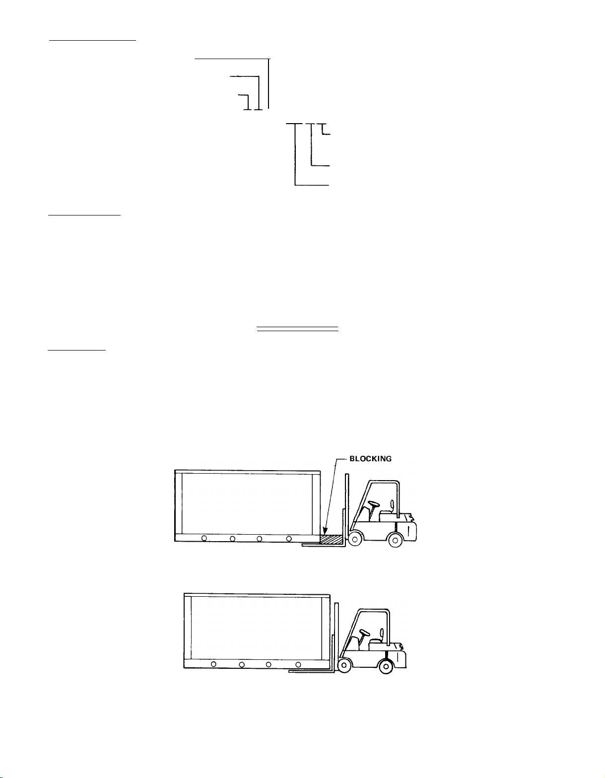
Care should be taken to avoid rough handling or shock due to dropping
the unit.
base,
and block the pushing vehicle away from the unit to prevent
damage to the sheet metal cabinet.
FIGURE 1
Do not push or pull the unit from anything other than the
(See Figure 1.)
SUGGESTED PUSHING ARRANGEMENT
page
4
GOOD PUSHING ARRANGEMENT
CABINET DAMAGE UNLIKELY
POOR PUSHING ARRANGEMENT
CABINET DAMAGE LIKELY
Page 5
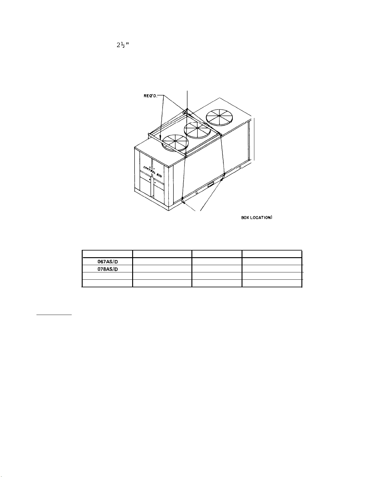
Never allow any part of the unit to fall during unloading or moving
as this may result in serious damage.
To lift the unit,
of the unit.
2+"
diameter lifting holes are provided in the base
Spreader bars and cables should be arranged to prevent
damage to the condenser coils or unit cabinet.
FIGURE 2
SPREADER BAR
SUGGESTED LIFTING ARRANGEMENT
REQD.
-MUST USE THESE RIGGING HOLES
OTE
CONTROL 60x
(N
(See Figure 2.)
L~cATI~NI
TABLE 1
ALP UNIT SIZE
067ASlD
078ASlD
089A
106A
UNIT WEIGHT
SHIPPING WEIGHTS
(Ibs)
4125
4308
4963
5134
ALP UNIT SIZE
126A
136A
149A
159A
UNIT WEIGHT
6021
6095
6873
7202
(Ibs)
Location
Due to the vertical condenser design, it is recommended that certain
precautions be taken before installation to orient the unit so that
prevailing winds blow parallel to the unit length thus minimizing
effects on condensing pressure.
the unit in this manner,
a wind deflecting fence should be consi-
If it is not practical to orient
dered.
It is also necessary to provide adequate clearance on all sides of
the unit for service access and satisfactory performance.
60 in.
(1 fan diameter) should be allowed on each side of the unit
for condenser air inlet and compressor removal on units 067
At least
&
078.
If parallel units are installed side by side, 120 in. should be allowed between units.
atures and enhance system performance and operating economy.
This will prevent excessive condensing temper-
Clear-
ance for service access should be at least 78 in. at the control cen-
ter end for compressor removal on units 089 through 159 and 42 in.
on units 067 and 078.
the control center for ease of access to bearings and drives.
Allow 36 in.
clearance at the end opposite
These
clearances are illustrated in Figure 3.
page 5
Page 6
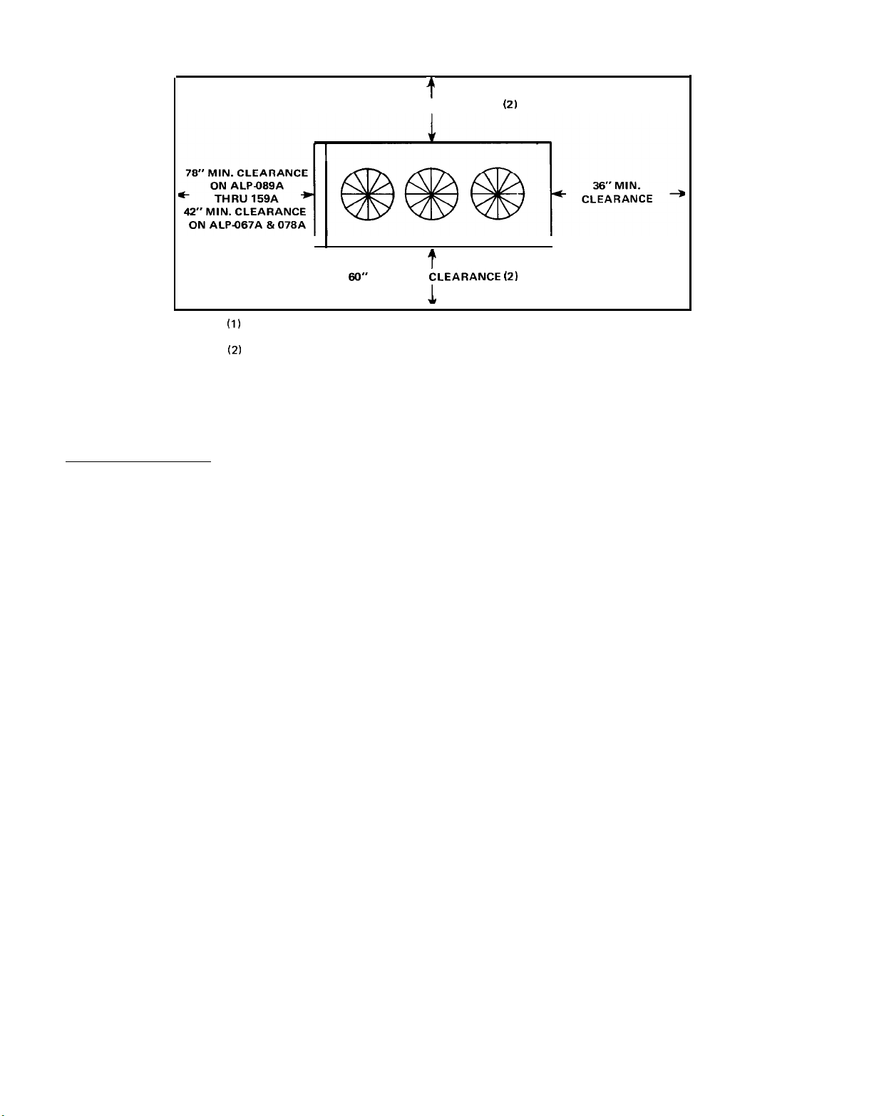
FIGURE 3 CLEARANCE AROUND UNIT
t
CLEARANCE
(2)
NOTE:
60” MINIMUM CLEARANCE (2)
60”
MINIMUM
(I)
Minimum vertical clearance above unit should be 10
feet.
(2) Clearance to condenser coil must be increased if more
than one side is obstructed or between adjacent units.
Consult your
McQUAY
sales representative.
Service Access
Each end of the unit must be accessible after installation for peri-
odic service work.
Compressors and manual liquid line shutoff valves
are accessible from the control center end of the unit through re-
movable access panels on unit sizes 089 through 159 and hinged side
access doors on unit sizes 067 and 078.
and starting controls are located in the unit control center.
are protected by a keylocked,
internal"dead front"
doors for protection of service personnel from
weatherproof enclosure which contains
All operational, safety,
They
high voltage starting controls while servicing low voltage operational controls.
just below the main control center.
All resettable or adjustable controls are located
There is one resettable control
enclosure on each side of the unit and each enclosure contains con-
trols for compressors on that side of the unit.
Capped connections
for field service gauges are also located inside these enclosures.
In addition,
each of these enclosures are removable to improve access
to compressors for field replacement.
The condenser fans, motors,
keylocked access door.
in,
and drives are accessible through a walkThe access door is located at the end of
the unit opposite the control center.
An internal fan guard is located below the condenser fans and drives
on units 089 through 159.
This guard must be removed to service the
fan drives but MUST always be reinstalled when service work is com-
plete.
On unit sizes 067 and 078,
an interlock switch kills power to conden-
ser fans whenever the door is opened for service work on fans or
drives.
CAUTION:
Disconnect all power to the unit while servicing condenser
fan drives.
page
6
Page 7
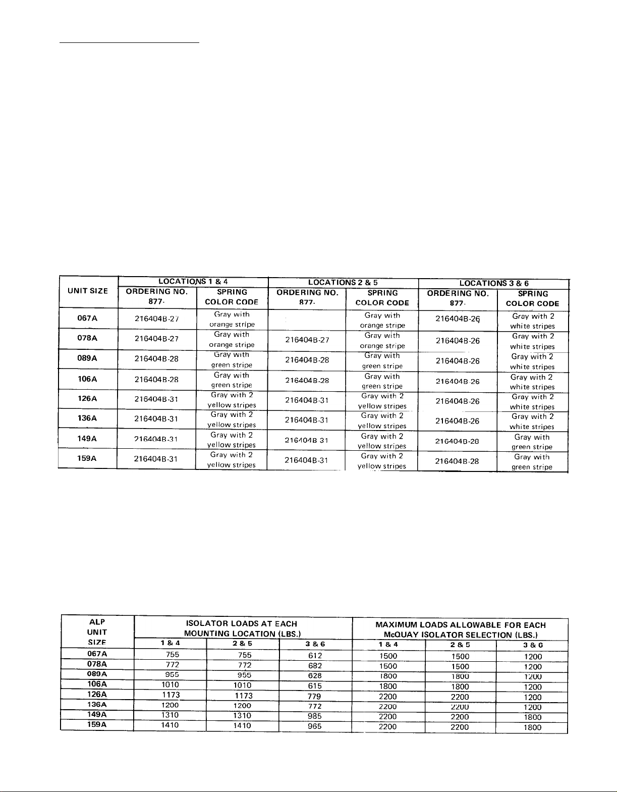
Vibration Isolators
Vibration isolators are recommended for all roof mounted installa-
tions or wherever vibration transmission is a consideration.
2 lists spring isolators for all ALP unit sizes.
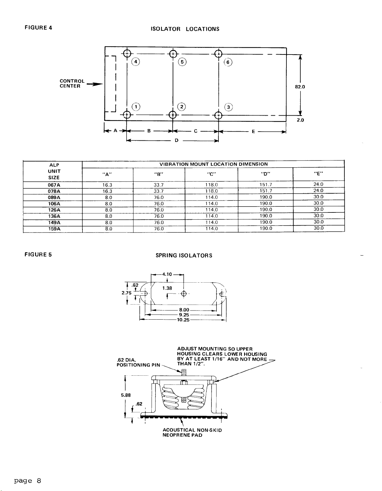
Figure 4 shows
isolator locations in relation to the unit control center.
gives dimensions that are required to secure each
McQuay
isolator
Table
Figure 5
selection to the mounting surface.
Table 3 shows the isolator loads at each location shown in Figure 4
and the maximum loads for each McQuay selection.
TABLE 2
VIBRATION
ISOLATORS
216404B-27 2164046-26
TABLE 3
IS0 LATOR LOADS
page 7
Page 8
Page 9
REFRIGERANT PIPING
General
McQuay type ALP condensing units are adaptable to either chilled
water or air handling air conditioning applications.
The only restriction on applications is that the evaporator be selected for a
system using refrigerant 22.
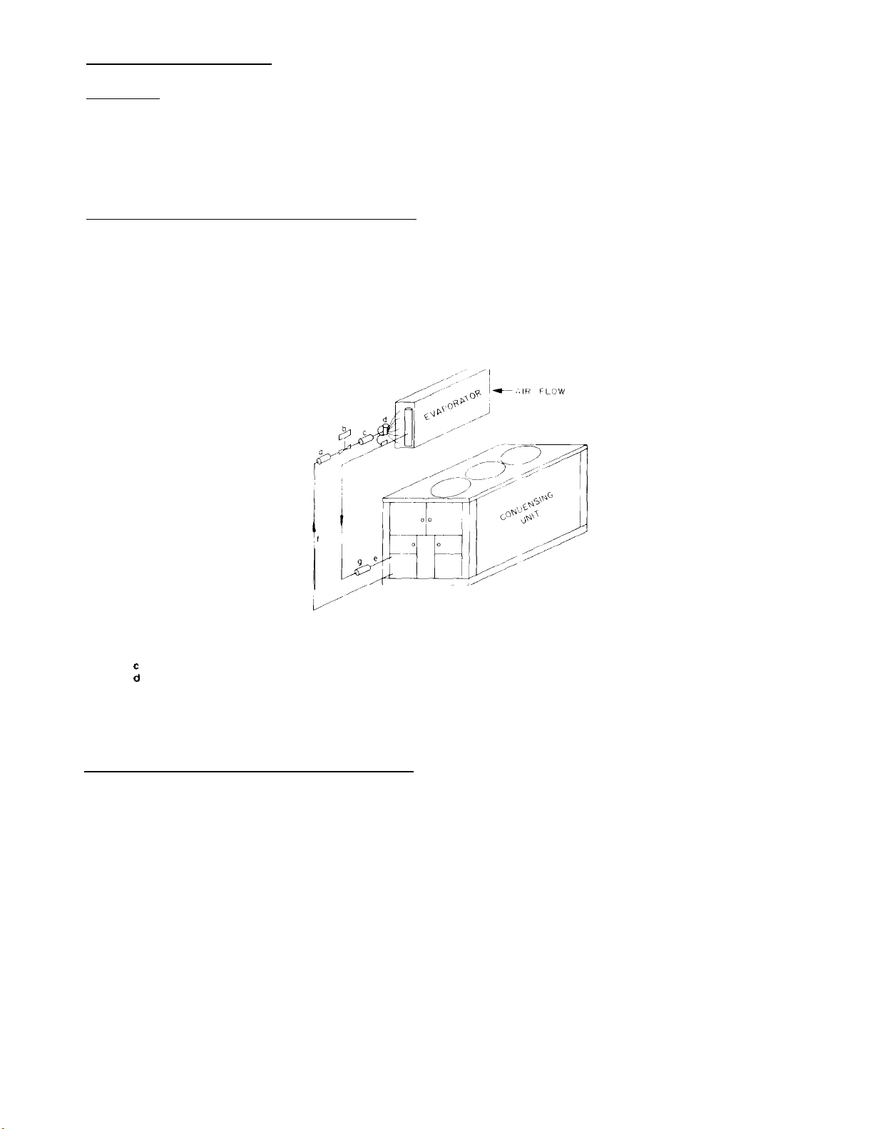
Evaporator Above Condensing Unit
Figure 6 shows an installation where the evaporator is installed
above the condensing unit.
It is shown for an air handling installation but all components shown are recommended for chilled water
installations except that a refrigerant distributor is not usually
required for shell-and-tube evaporators.
FIGURE 6
Legend
Filter-drier
a
b
Solenoid valve
Sight-glass/moisture indicator
Thermal expansion valve
:
e
Suction line, pitched toward compressor
f
Liquid line
Vibration absorber
9
EVAPORATOR ABOVE CONDENSING UNIT
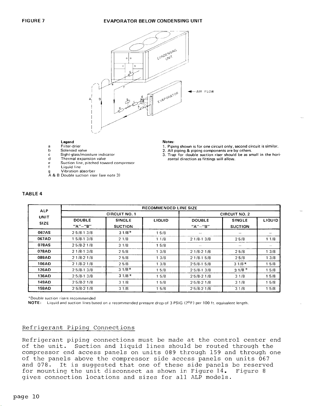
Evaporator Below Condensing Unit
Notes:
1. Piping shown is for one circuit only, second circuit is similar.
2. All piping & piping components are by others.
Figure 7 shows an installation where the evaporator is installed below the condensing unit.
It is shown for an air handling installation but all components shown are recommended for chilled water installations except that a refrigerant distributor is not usually re-
quired for shell-and-tube evaporators.
Mote that a double suction
riser is shown for this arrangement.
Risers
"A + B" are sized so that their combined cross-sectional in-
ternal area will allow full load unit operation without excessive
pressure drop (see notes, Table 4).
Riser
"B"
is sized to provide
adequate suction gas velocity for proper oil return at minimum load
conditions.
in riser "A"
the trap shown in riser "A"
This riser becomes effective only when the trap shown
fills itself with oil.
It should be emphasized that
should be designed to contain a minimum
internal volume to keep the total system oil requirements at a minimum.
Table 4 gives recommended line sizes for both single and double
suction lines and for liquid lines.
page
9
Page 10
Page 11
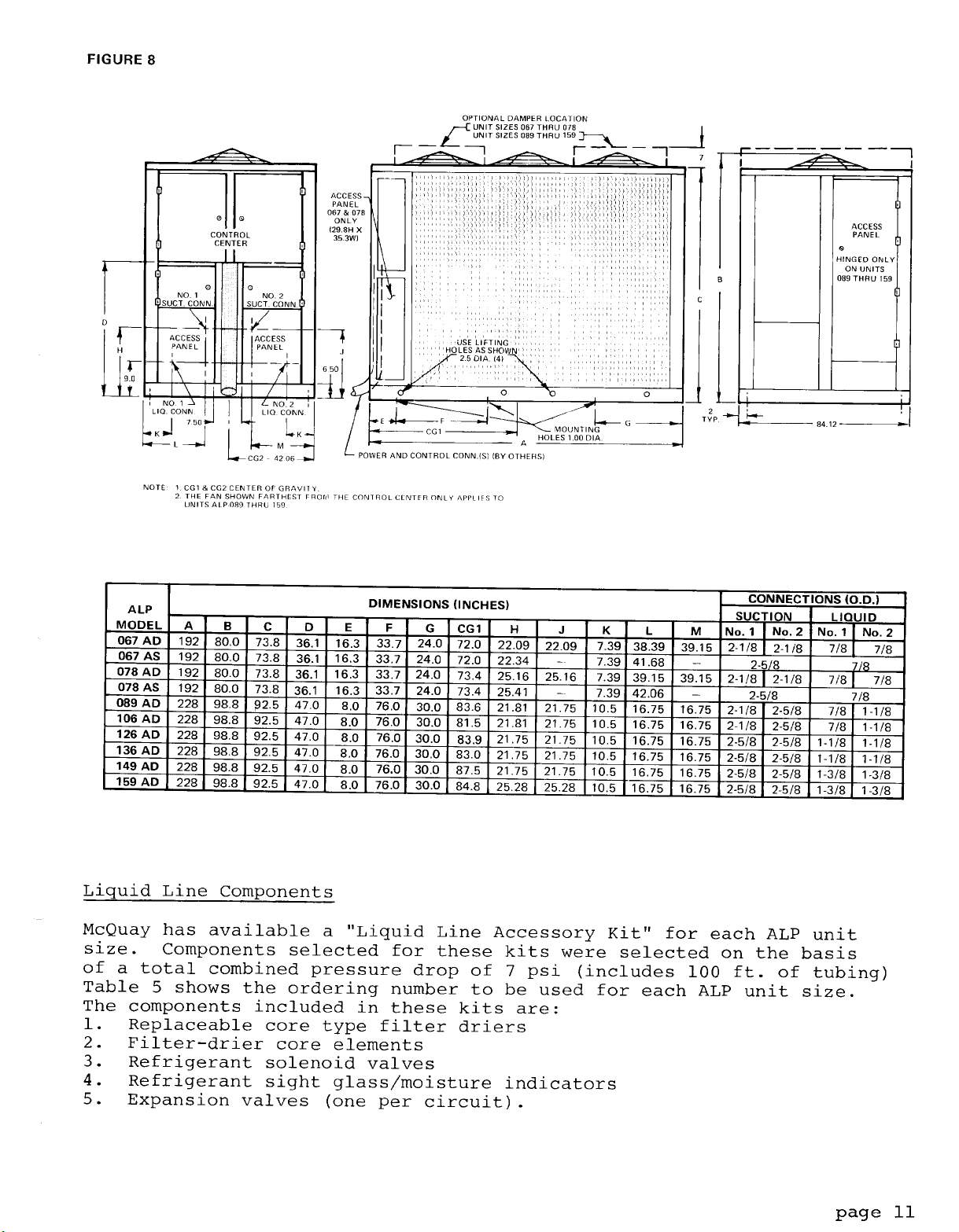
Page 12
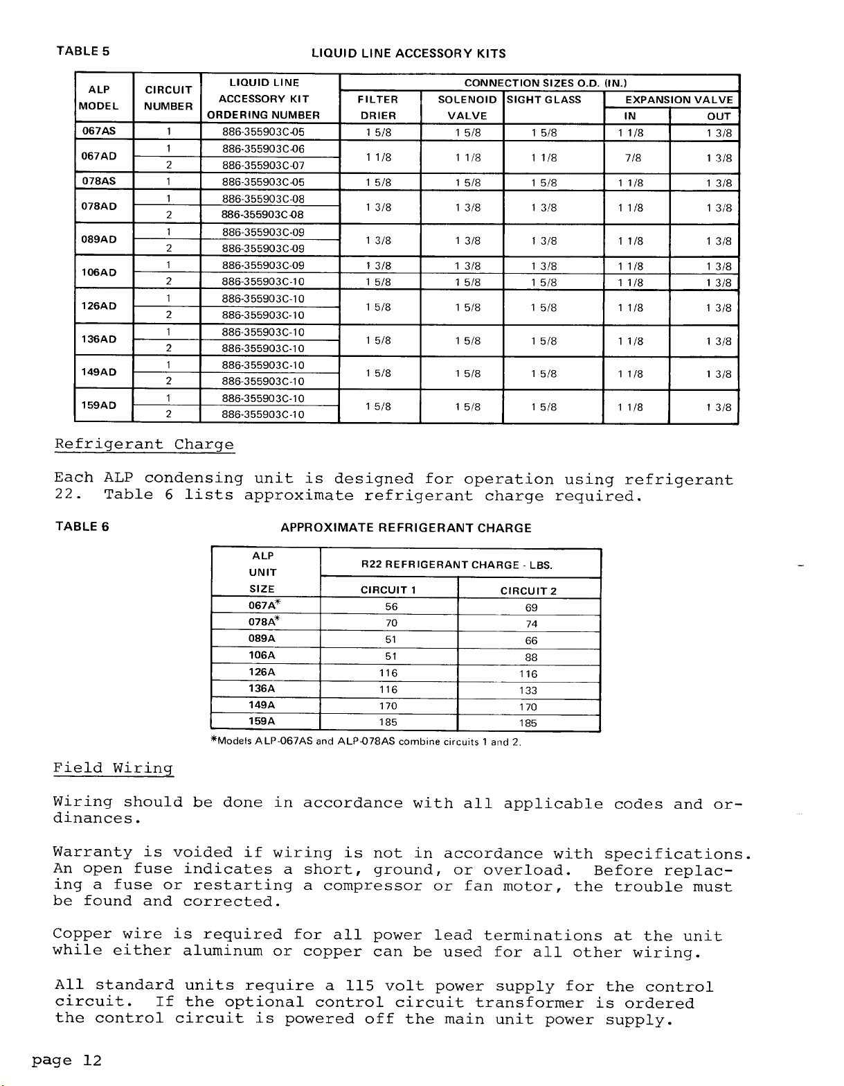
Page 13
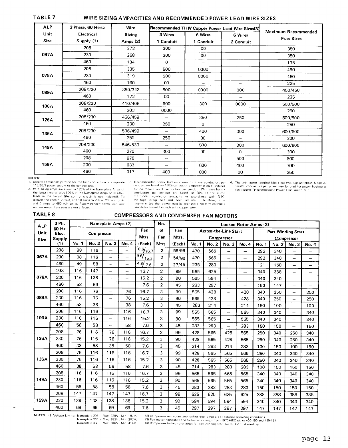
Page 14
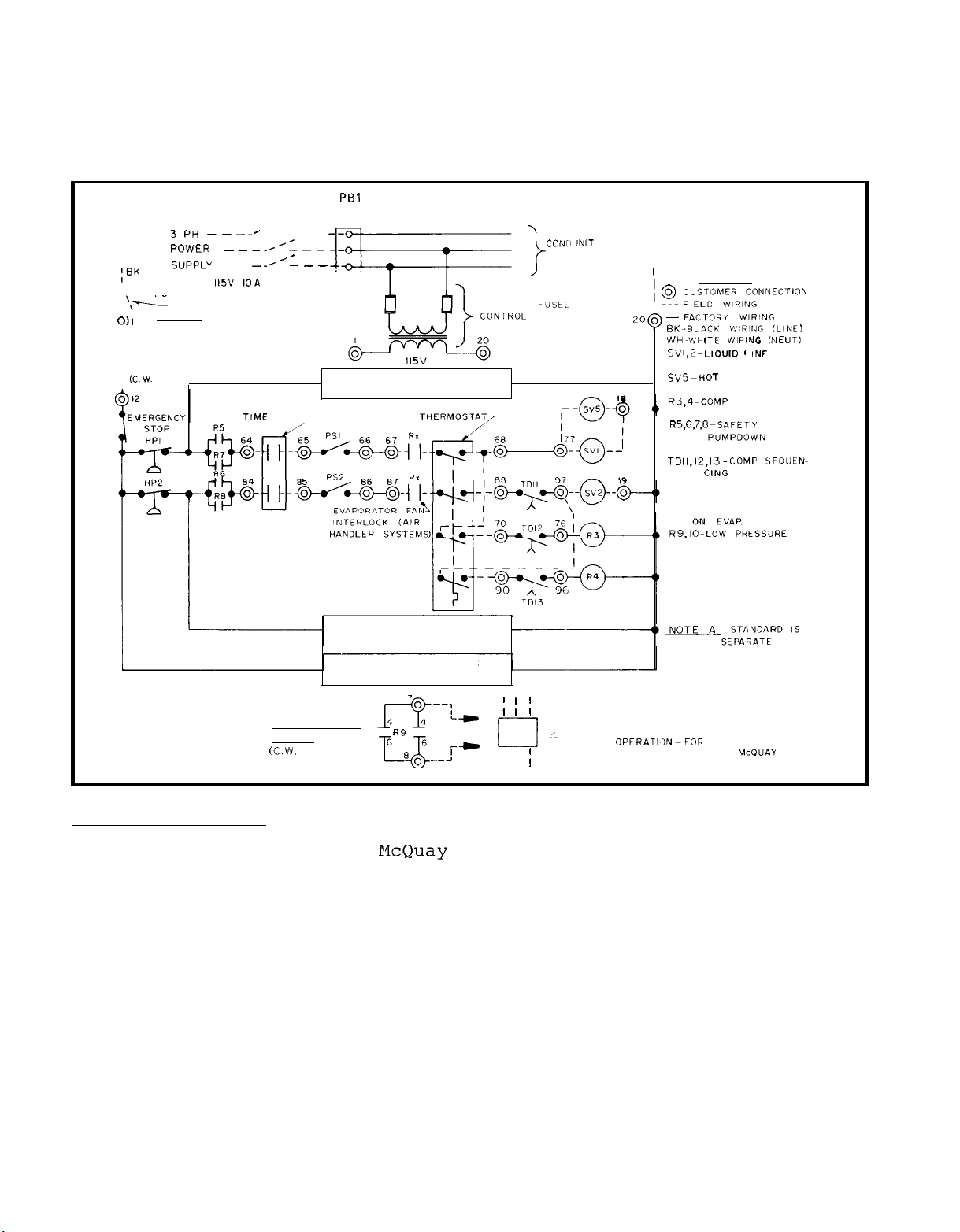
Figure 9 shows typical field wiring that is required for unit instal-
lation.
(SVl & SV2),
Items that require field wiring are:
optional hot gas bypass solenoid
liquid line solenoids
(SV5)
and the cooling
thermostat as well as the unit power supplies.
FIGURE 9
;BK
\
I
01
0 II
8
-FLOW SWITCH
PBl
DISCONNECT
BY OTHERS--\,,< TERMINAL BLOCK
3pH ---_H
POWER
SuppLy
_ _
SEPARATE
POWER FOR CONTROLS
‘,‘--
DISCONNECT BY OTHERS
A
NOTE
FUSE-IO A
(C.W.
SYSTEMS)
___/-:__
II?,“-IOA
___
__I’_
TIME
CLOCK;;-
UNIT MAIN
c
-
-
REFRIGERANT CIRCUIT I
SAFETY AND OPERATING
TYPICAL FIELD WIRING
OPTIONAL
TRANSFORMER
CONTROLS
FdSEU
CONI, llNlT
COMPRESSORS
AND FAN MOTORS
WH
I
i g_ ~~~SLT~OM~~~,~~NNECTION
I
LEGEND
irJH_WHlTt
SVl,2-LIOUID ’ INE
SVS-HOT
R3,4-COMP.
R5,6,7,E
PSI.2 -PUMPDOWN
TDl1,12,13-COMP
Rx-EVAP. FAN INTERLOCK
WlhlNG
SOL. VALVE
GAS BY PASS
SOL VALVE
384 START
RELAYS
-SAFETY
SWITCHES
CING TIME DELAYS
PREVENTS OPENING
SV’S WITHOUT LOAD
RELAYS PROVIDE
RECYCLING PUMP
DOWN DURING OFF
SEASON
fNEUT1.
RELAYS
SEOUEN-
PUMP STARTER
CIRCUIT
CC. W.
SYSTEMS1
REFRIGERANT CIRCUIT
SAFETY AND OPERATING
CONTROLS
UNIT CONDENSER
OPERATING CONTROLS
R9
6
6
a0 __:
T
2
FANS
’
I
1
I
I
I
PUMP STARTER
RIO
-C
NOTE; CIRCUIT SHOWN ASSUMES CONTINUOUS
I I
1
I I
I
POWER SUPPLY
FOR CONTROLS
PUMP
OPERATIIN~FOR
PUMP OPERATION CONSULT
INTERMITTENT
McOUAY
Thermostat Wiring
Since it is impossible for
McQuay to anticipate the type of installa-
tion that an ALP condensing unit may be used on, we do not factory
install a thermostat.
We do,
however,
provide numbered terminals in-
side the unit control center to which a thermostat may be connected.
These terminals are shown and labeled "Terminals For Thermostat" on
the electrical schematics.
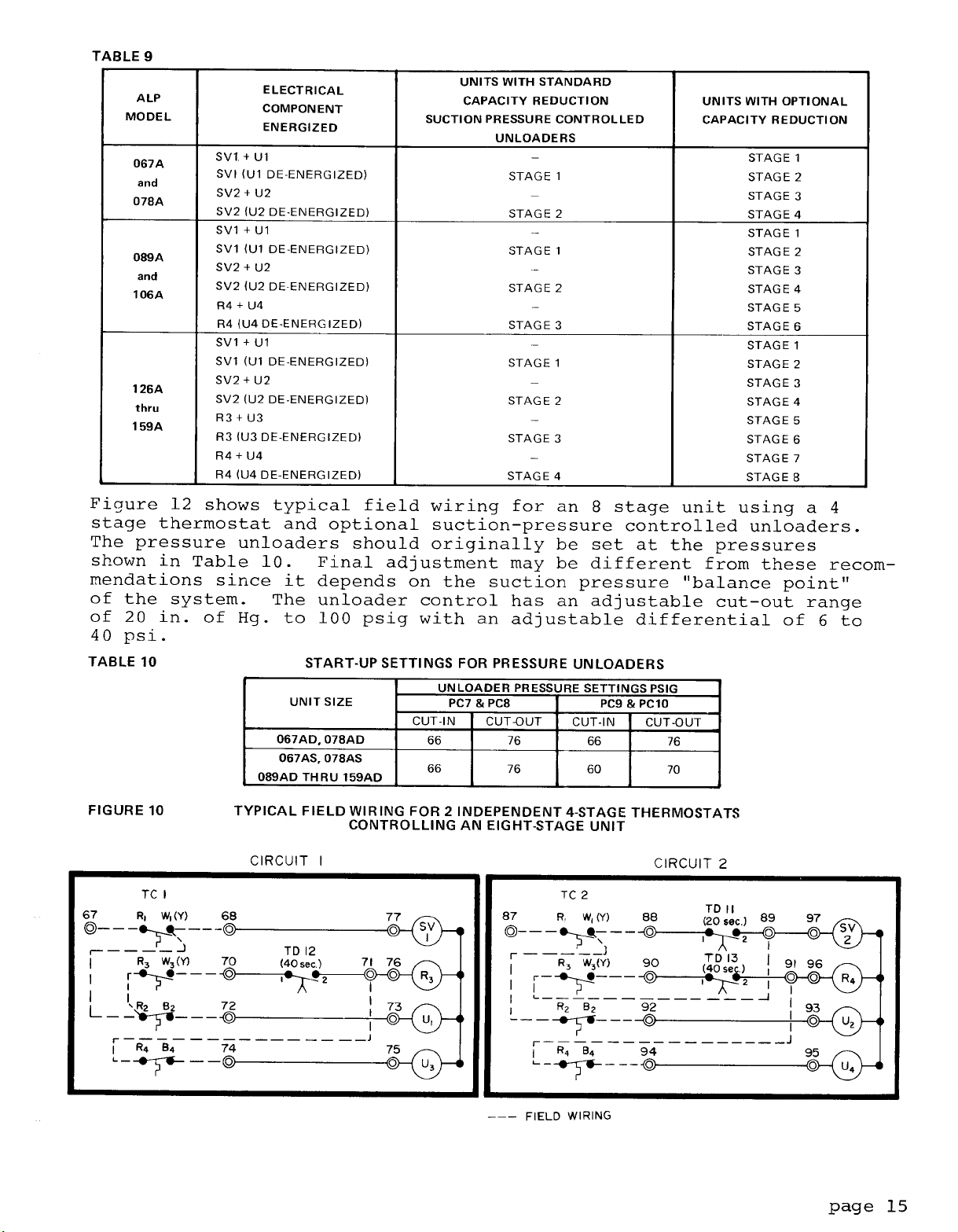
On a two circuit unit it is important to connect the thermostat so
that as successive stages of cooling are called for, the compressors
in the unit will be started to alternately increase the condenser
load from refrigerant circuit 1 to circuit 2.
in Table 9.
Figure 10 shows how to install 2 independent four stage
This is illustrated
thermostats for controlling an 8 stage unit and Figure 11 shows typical field wiring for an 8 stage thermostat.
page 14
Page 15
Page 16

Page 17

Page 18

Flow Switch for Chilled Water Applications
A WATER FLOW SWITCH MUST BE MOUNTED in either the entering or leaving water line to insure that there will be adequate water flow and
cooling load to the evaporator before the unit can start.
safeguard against slugging the compressors on start up.
This will
It also
serves to shut down the unit in the event that water flow is interrupted to guard against evaporator freeze up.
A flow switch is available from McQuay under ordering number
175033x-00.
size from 1" to 6" nominal.
to close the switch and are listed in Table 11.
It is a "paddle"
type switch and adaptable to any pipe
Certain minimum flow rates are required
Installation should
860-
be as shown in Figure 13.
TABLE 11
FLOW SWITCH MINIMUM FLOW RATES
NOMINAL
PIPE SIZE
(INCHES)
1
1
l/4
1
l/2
2
2
l/2
3
4
5
6
MINIMUM REQUIRED
FLOW TO ACTIVATE
SWITCH
(GPM)
6.00
9.80
12.70
18.80
24.30
30.00
39.70
58.70
79,20
FIGURE 13
G%
AFTER
SWiTCH
FLOW DIRECTION
MARKED ON SWITCH
1.00 NPT FLOW SWITCH
CONNECTION
O:Nl.,.
BEFORE SWITCH
Electrical connections in the unit control center should be made at
terminals 11 and 12.
should be wired between these two terminals.
The normally open contacts of the flow switch
There is also a set of
normally closed contacts on the switch that could be used for an indicator light or an alarm to indicate when a "no flow" condition
exists.
Evaporator Fan Interlock for Air Handler Coil Installations
It is important to interlock the air handler evaporator fan with the
condensing unit control center to insure that there will be a cooling
load on the evaporator before the unit can start, to prevent compressor slugging.
is available in the unit control center for this purpose.
A pair of terminals for each refrigerant circuit
These
terminal numbers are shown in Figure 12.
page 18
Page 19

Control Center
UNIT LAYOUT AND PRINCIPLES OF OPERATION
All electrical
ter with keylocked,
posed of three separate enclosures.
largest and contains all of the 208,
fan motor starting controls.
partitioned separately are the exposed terminal type
ational controls. A "dead front"
controls are enclosed in a weatherproof control cen-
hinged access doors.
The control center is com-
The upper enclosure is the
230, or 460 volt compressor and
Also included in this enclosure but
-
115 volt oper-
cover over the high voltage section
protects service personnel from high voltage starting controls while
servicing low voltage operational controls.
Below the upper enclosure are two smaller,
contain 115 volt adjustable or resettable controls.
separate enclosures that
There is one of
these enclosures on each side of the unit, and each contains controls
for the compressors on that side.
Power supply conduits are intended to come into the bottom of the
upper enclosure and between the two lower enclosures.
It is recommended that the unit disconnect switch be mounted away from the unit
but Figure 14 recommends a unit mounting arrangement if the discon-
nect must be unit mounted.
FIGURE 14
POWER CONDUIT ENTRY
Power
into
unit
CONTROL
CENTER
DISCONNECT
ALP-089A THRU 159A
~
ALP
-
067A THR U 078A
page 19
Page 20

Page 21

Page 22

Sequence of Operation
The following sequence of operation is typical for ALP Seasoncon air
cooled condensing unit operation.
unit,
referred to,
pressors are indicated in parentheses.
but where components that apply to the fourth compressor are
the equivalent components for the third and second com-
It is written for a 4 compressor
With the control circuit power on,
and manual pumpdown switches
115 volt power is applied through control circuit fuse
pressor crankcase heaters
to the contacts of low pressure switches
When the remote time clock, ambient thermostat, manual shutdown
switch and/or evaporator fan interlocks energize the thermostatic
circuit,
pressor motor protectors
alarm condition,safety relays R5 through R8 (R7,
closed applying power to the temperature control thermostat. At this
point the unit will operate automatically in response to the thermo-
stat.
On a call for cooling,
gizes liquid line solenoid valve
refrigerant to flow into the evaporator.
builds up,
relay
compressor number 1. Closing relay
denser fan relay
condenser fan motor contactors Mll,12
or
Mll, & 12 on 2 compressor units.
and provided that high pressure controls HP1 and 2 and com-
the temperature control thermostat
low pressure control
R9
which closes to energize compressor contactor Ml, starting
R17.
Closing its contacts and providing power to
PSl
HTRl
through HTR4, (HTR3,
MPl
through PIP4
control stop switch
and PS2 closed ("Auto." position),
LPl
and LP2.
(MP3,
SVl,
LPl
opening the valve and allowing
As refrigerant pressure
closes,energizing low pressure
R9
contacts also energizes con-
&
13 on 3 & 4 compressor units,
MP2) do not sense an
R6)
Sl
closed,
Fl
to the com-
HTR2),
are energized
and also
TCl
ener-
If additional stages of cooling are required, temperature control
thermostat
delay relay
sequence in refrigerant circuit number 2.
On 3 and 4 compressor units,if additional cooling is still required,
the third and fourth stages of temperature control thermostat
energize the third and fourth compressors after time delay relays
TD12 and TD13 have sequenced closed.
Pumpdown Cycle
As the temperature control thermostat is satisfied, it opens its con-
tacts,
valve to close. When the compressor has pumped most of the refrig-
erant from the evaporator to the condenser, the low pressure control
LPl
opens,shutting down the compressor and condenser fan motors.
Should a closed solenoid valve allow refrigerant to leak to the low
side of the refrigerant circuit during unit "off" time, the buildup
in pressure will cause the low pressure control to close, energizing
the low pressure relay and starting the compressor for pumpdown.
NOTE:
TCl
energizes liquid line solenoid valve SV2 after time
TDll
has sequenced closed,to initiate the same starting
TCl
de-energizing liquid line solenoid valve
Models ALP-067AS and 078AS have single refrigerant circuits
but dual pumpdown switches
these units down,
switches be moved to the "man.pumpdown" position simultane-
ously.
it is recommended that both pumpdown
(PSl &
PS2). To manually pump
SVl,
causing the
page 22
Page 23

Page 24

Page 25

Page 26

Page 27

Page 28

Page 29

Page 30
Page 31

Page 32

Page 33

Page 34

Page 35

Page 36

Page 37

START-UP AND SHUT-DOWN
Pre Start--Up
1.
With all electric disconnects open, check
all screw or lug type
electrical connections to be sure they are tight for good electrical contact.
fore shipment,
Although all factory connections are tight be-
some loosening may have resulted from shipping
vibration.
2.
a) On chilled water installations,
check to see that all water
piping is properly connected.
b)
Open all water flow valves and start the chilled water pump.
Check all piping for leaks and vent the air from the evaporator
and system piping to obtain clean,
non-corrosive
water in the
evaporator circuit.
Check the compressor oil level.
3.
should cover at least
Remove the
4.
(8)
compressor shipping blocks that are attached to the
l/2
of the oil sight glass.
compressor rails and the base of the unit.
Prior to start-up, the oil level
The ALP 067 and 078
do not have shipping blocks.
5.
Check the voltage of the unit power supply and see that it is
+
within the
ance must be within
6.
Check the unit power supply wiring for adequte ampacity and a
10%
tolerance that is allowed.
t
2%.
Phase voltage unbal-
minimum insulation temperature rating of 75C.
Verify that all mechanical and electrical inspections have been
7.
completed per local codes.
See that all auxiliary control equipment is operative and that
8.
an adequate cooling load is available for initial start up.
Initial Start-Up
1.
Open the compressor suction and discharge shutoff valves until
back seated.
2.
Open the manual liquid line shutoff valve at the outlet of the
Always replace valve seal caps.
subcooler.
Check to see that pumpdown switches
3.
pumpdown"
IIon"
position.
4.
Adjust the dial on the temperature controller to the desired
position and the control stop switch
(PSl &
PS2)
are in the
(Sl)
Isman.
is in the
chilled water or leaving air temperature.
5. Throw the main power and control circuit disconnects to the "on"
position.
CAUTION:
Allow the crankcase heaters to operate for at least 8 hours prior
6.
Most relays and terminals in the unit control center are
hot with
Sl
and the control circuit disconnect on.
to start-up.
Start the auxiliary equipment for the installation.
7.
Start the system by moving pumpdown switches
8.
"auto.
After system performance has stabilized,
9.
pumpdown" position.
it is necessary that the
"Compressorized Equipment Warranty Form" (form no.
completed to obtain full warranty benefits.
(PSl &
PS2) to the
206036A)
be
This form is shipped
with the unit and after completion should be returned to McQuay's
Service Department through your sales representative.
page
37
Page 38

Temporary Shut-Down
Move pumpdown switches
(PSl &
After the compressors have pumped down,
pump or evaporator fan.
PS2) to the "man. pumpdown" position.
turn off the chilled water
It is especially important on chilled water
installations that the compressors pump down before the water flow
to the evaporator is interrupted to avoid freeze up.
Start-Up After Temporary Shut-Down
1.
Start the chilled water pump or evaporator fan.
2.
With control stop switch
switches
3.
Observe the unit operation for a short time to be sure that the
(PSl &
PS2) to the '"auto. pumpdown" position.
(Sl)
in the
"on"
position, move pumpdown
compressors do not cut out on low oil pressure.
Extended Shut-Down
1.
Close the manual liquid line shutoff valves.
2.
After the compressors have pumped down, turn off the chilled
water pump or evaporator fan.
3.4.Turn off all power to the unit and to the auxiliary equipment.
Move the control stop switch
5.
Close the compressor suction and discharge valves.
6.
Tag all opened disconnect switches to warn against start up be-
(Sl)
to the
"off"
position.
fore opening the compressor suction and discharge valves.
Start-Up After Extended Shut-Down
1.
Inspect all auxiliary equipment (pumps, fans, etc.) to see that
each device is in satisfactory operating condition.
2.
Remove all debris that has collected on the surface of the con-
denser coils.
3.
Open the compressor suction and discharge valves.
4.
Open the manual liquid line shutoff valves.
5.
Check to see that pumpdown switches
pumpdown" position.
6.
Turn on the electric power to the unit and other parts of the
system.
7.
Allow the crankcase heaters to operate for at least 8 hours prior
to start-up.
8.
On chilled water installations,
purge the water piping as well as the evaporator.
9.
Check to see that the control stop switch (Sl) is in the
position.
CAUTION:
10.
Start the unit by moving pumpdown switches
"auto.
11.
After running the unit for a short time, check the oil level in
Most relays and terminals in the unit control center are
hot with
Sl
and the control circuit disconnect on.
pumpdown" position.
each compressor crankcase and check for flashing in the refri-
gerant sight glass.
(PSl 6;
PS2) are in the "man.
start the chilled water pump and
"on"
(PSl &
PS2) to the
page 38
Page 39

SYSTEM MAINTENANCE
General
On initial start up and periodically during operation it will be
necessary to perform certain routine service checks.
Among these
are checking the compressor oil level and taking condensing, suction and oil pressure readings.
During operation, the oil level
should be visible in the oil sight glass with the compressor run-
ning.
On units ordered with gauges,condensing,suction and oil
pressures can be read from the unit control center. The gauges
are factory installed with a manual shutoff valve on each gauge
line.
The valves should be closed at all times except when gauge
readings are being taken. On units ordered without gauges, the
gauge shutoff valves come factory installed inside the unit control
center for convenient connection of service gauges form outside the
unit.
Fan Shaft Bearings
The fan shaft bearings do not require lubrication at the time the
unit is put into service.
The fan shaft bearings should be greased
once a year using STANDARD OIL COMPANY AMCO Multi-Purpose Lithium
Grease.
DO NOT OVERLUBRICATE.
Fan Motor Bearings
All fan motors are ball bearing,
the addition of grease at the time of installation.
pre-lubricated and do not require
Periodically,
the ball bearings should be cleaned and the grease renewed, to gain
the ultimate in service from the motor bearings.
Extreme care must be exercised to prevent foreign matter from enter-
ing the ball bearings.
It is also important to avoid overgreasing.
Only a high grade clean mineral grease having the following characteristics should be used.
Consistency: A little stiffer than that
of Vaseline,maintained over the operating temperature range; melting
point preferably over 150C
(302OF);
freedom from separation of oil
and soap under operating and storage conditions and freedom from abrasive matter, acid, alkali and moisture.
Specific greasing instructions are to be found on the label attached
to the unit and should be generally followed.
Electrical Terminals
CAUTION:
ELECTRIC SHOCK HAZARD,
TURN OFF ALL POWER BEFORE CONTINU-
ING WITH FOLLOWING SERVICE.
All power electrical terminals should be retightened every 6 months,
as they tend to loosen in service due to normal heating and cooling
at the wire.
Compressor Oil Level
Because of the large refrigerant charge required in an air cooled
condensing unit it is usually necessary to put additional oil into
the system.
The oil level should be watched carefully upon initial
start up and for sometime thereafter.
page 39
Page 40

At the present time,Suniso
Copeland for use in these compressors.
#3GS
oil is the only oil approved by
The oil level should be maintained at about the midpoint of the sight glass on the compressor
body.
Condensers
Condensers are air cooled and constructed with
bonded in a staggered pattern into rippled aluminum fins.
3/8 0-D.
copper tubes
No maintenance is ordinarily required except the occasional removal of dirt
and debris from the outside surface of the fins.
taken not to damage the fins during cleaning.
Care should be
Periodic use of the
purge valve on the condenser will prevent the buildup of non-conden-
sables.
Refrigerant Sight Glass
The refrigerant sight glasses should be observed periodically.
monthly observation should be adequate.)
A clear glass of liquid in-
(A
dicates that there is adequate refrigerant charge in the system to
insure proper feed through the expansion valve.
Bubbling refriger-
ant in the sight glass indicates that the system is short of refri-
gerant charge. On sight glasses ordered from XcQuay as part of the
"Liquid Line Accessory Kits" listed on page 12, an element inside
the sight glass indicates what moisture condition corresponds to a
given element color.
dition after a few hours of operation,
If the sight glass does not indicate a dry con-
the unit should be pumped down
and the cores in the filter-driers changed.
SERVICE
SERVICE ON THIS EQUIPMENT TO BE PERFORMED BY QUALIFIED REFRIGERATION SERVICE PER-
SONNEL. CAUSES FOR REPEATED TRIPPING OF SAFETY CONTROLS MUST BE INVESTIGATED AND
CORRECTED.
Filter-Driers
To change the filter drier core(s)
pumpdown switches
(PSl &
PS2) to the "man. pumpdown" position.
,
pump the unit down by moving
Turn
off all power to the unit and install jumpers from terminals 21 to
24 and 41 to 44.
unit by moving pumpdown switches
position.
Close the manual liquid line shutoff valve(s) and when
evaporator pressure reaches 0 PSIG,
(Sl)
to the "off" position.
Turn power to the unit back on and re-start the
(PSl &
PS2) to the "auto. pumpdown"
move the control stop switch
This will close the liquid line sole-
noid valve(s) and isolate the short section of refrigerant piping
containing the filter-drier(s).
Remove the cover plate from the
filter-drier shell and replace the core(s).
After core replacement,
replace the cover plate.
A leak check around the flange of the filter-drier shell is recommended after the
cores have been changed.
page
40
Page 41

Liquid Line Solenoid Valve
The liquid line solenoid valves,
pumpdown during normal unit operation,
maintenance.
They may, however,require replacement of the solenoid
which are responsible for automatic
do not normally require any
coil or of the entire valve assembly.
The solenoid coil may be removed from the valve body without opening
the refrigerant piping by moving pumpdown switches
the
1'man.
pumpdown" position.
The coil can then be removed from the
(PSl & PS2)
to
valve body by simply removing a nut or snap ring located at the top
of the coil.
replacement.
returning pumpdown switches
The coil can then be slipped off its mounting stud for
Be sure to replace the coil on its mounting stud before
(PSl
&
PS2)
to the "auto. pumpdown" po-
sition.
To replace the entire solenoid valve,
the unit must be pumped down
by use of the manual liquid line shutoff valve.
Thermostatic Expansion Valve
The expansion valve is responsible for allowing the proper amount of
refrigerant to enter the evaporator regardless of cooling load. It
does this by maintaining a constant superheat.
(Superheat is the
difference between refrigerant temperature as it leaves the evapor-
ator and the saturation temperature corresponding to the evaporator
pressure.)
15F.
On valves purchased through
Typically,
superheat should run in the range of
McQuay,
the superheat setting can
10F
to
be adjusted by removing a cap at the bottom of the valve to expose
the adjustment screw.
Turn the screw clockwise (when viewed from the
adjustment screw end) to increase the superheat setting and counterclockwise to reduce superheat.
Allow time for system rebalance af-
ter each superheat adjustment.
INLET
POWER ELEMENT
(CONTAINS DIAPHRAGM)
OUTLET
SPRING
ADJUSTMENT SCREW
CAP
page 41
Page 42

Trouble Shooting Chart
PROBLEM POSSIBLE CAUSES
1. Main switch open.
2. Fuse blown. Circuit breakers open.
3. Thermal overloads tripped.
Compressor will
not run
Compressor noisy 2. Improper piping support on suction or 2. Relocate, add or remove hangers.
or vibrating liquid line.
High Discharge
Pressure
Low Discharge
Pressure
High Suction 2.
Pressure
Low Suction
Pressure
Compressor will not 1. Defective
unload or load up. 2. Pressurestat not set for application. 2. Reset pressurestat setting to fit applicatron.
Little or no oil
pressure
Compressor loses
oil
Motor overload
relays or circuit
breakers open
Compressor thermal
protector switch
open.
4. Defective contactor or coil. 4. Repair or replace.
5. System shut down by safety devices.
6. No cooling required.
7. Liquid line solenoid will not open. 7. Repair or replace coil.
8. Motor electrical trouble 8. Check motor for opens, short circuit, or burn out.
9. Loose wiring.
I.
Flooding of refrrgerant Into crankcase. 1. Check setting of expansion valve.
3. Worn compressor
1.
Non-condensibles in system.
2. System overcharged with refrigerant.
3. Discharge shut off valve partially closed.
4. Seasontrol out of adjustment 4. Adjust Seasontrot valves.
5. Fan not running.
I.
Faulty condenser temperature regulation.
2. Suction shut-off valve partially closed.
3. insufficient refrrgerant in system.
4. Low suction pressure.
5. Compressor operating unloaded. 5. See Corrective Steps for failure of compressor to load
1. Excessive load.
Expansron
3. Compressor unloaders open.
1. Lack of refrigerant.
2. Evaporator dirty. Plugged
3. Clogged
4. Clogged suction line or compressor suction. 4. Clean
gas strainers.
5. Expansion valve malfunctioning.
6. Condensing temperature too low.
7. Compressor will not unload. 7. See
1. Clogged suction oil strainer.
2. Excessive liquid
3. Oil pressure gauge defective.
4. Low oil pressure safety switch defective.
5. Worn
6. Oil pump reversing gear stuck in wrong
position.
7. Worn
8. Low oil level.
9. Loose fitting on oil lines.
10. Pump housing gasket leaks.
11. Flooding of refrigerant into crankcase.
1. Lack of refrrgerant.
2. Excessive compression ring blow-by.
1. Low voltage during high load conditions.
2. Defective or grounded wring in motor.
3. Loose power wiring.
4. High
5. Power line fault causing unbalanced voltage.
6. High ambient temperature around the
load relay.
7. Failure of second starter to pull in on
winding start systems.
1. Operating beyond design conditions.
2. Discharge valve partially shut.
3. Blown valve plate gasket.
valve
overfeedrng.
acr
liqurd lrne
011
pump.
bearrngs.
condensrng
filterdrier.
capacrty
control.
rn
crankcase.
temperature.
filters.
over-
part-
1.
2. Check electrical circuits and motor winding for shorts
3. Overloads are auto. reset. Check unit closely when
5. Determine type and cause of shutdown and correct it
6. None. Wait until unit calls for
9. Check all wire junctions, Tighten all terminal screws.
3. Replace.
I.
2. Remove excess.
3. Open valve.
5. Check belts and electrical
I.
2. Open valve.
3. Check for leaks. Repair and add charge.
4. See Corrective Steps for low suction pressure below.
1.
2. Check remote bulb. Regulate superheat.
3. See Corrective Steps below for failure of compressor
1.
2. Clean
3. Replace cartridge(s).
5. Check and reset for proper superheat.
6. Check means for regulating condensing temperature.
I.
1. Clean.
2. Check crankcase heater. Reset expansion valve for
3. Repair or replace. Keep valve closed except when
4. Replace.
5. Replace.
6. Reverse
7. Replace compressor.
8. Add oil.
9. Check and tighten system.
10. Replace gasket.
11. Adjust thermal expansion valve.
1.
2. Replace compressor.
1. Check supply voltage for excessive
2. Replace compressor motor.
3. Check all connections and tighten.
4. See Corrective Steps for high discharge pressure.
5. Check supply voltage. Notify power compnay. Do not
6. Provide ventilation to reduce heat.
7. Repair or replace starter or time delay mechanism.
I. Add facilities so that conditions are within allowable
2. Open valve.
3. Replace gasket.
POSSIBLE CORRECTIVE STEPS
Close switch.
or grounds. Investigate for possible overloading. Replace fuse or reset breakers after fault is corrected.
unit comes back on
before resetting safety switch.
Purge the non-condensibles.
Check condenser control operation.
up below.
Reduce load or add additional equipment.
to load up.
Check for leaks. Repair and add charge.
chemrcally.
strarners.
Correctrve Steps for failure of compressor to
unload.
Replace.
higher superheat. Check liquid line solenoid valve
operation.
taking readings.
drrectron
Check for leaks and repair Add refrigerant.
start until fault is corrected.
limits.
line.
cooling.
crrcuit.
of compressor rotation.
lrne
drip.
page 42
Page 43

IN-WARRANTY RETURN MATERIAL PROCEDURE
Compressor
Copeland Refrigeration Corporation has stocking wholesalers who main-
tain a stock of replacement compressors and service parts to serve
refrigeration contractors and servicemen.
When a compressor fails in warranty,
tative,
or McQuay Warranty Claims Department at the address on the
contact your local sales represen-
cover of this bulletin. You will be authorized to exchange the de-
fective compressor at a Copeland Wholesaler,or an advance replacement can be obtained. A salvage credit is issued to you by the whole-
saler on the returned compressor after Copeland factory inspection of
the inoperative compressor. Provide McQuay with full details and invoices and we
certain that the compressor is definitely defective.
will
reimburse the difference.
In this transaction, be
If a compressor
is received from the field that tests satisfactorily, a service charge
plus a transportation charge will be charged against its original credit value.
On all out-of-warranty compressor failures,
Copeland offers the same
field facilities for service and/or replacement as described above.
The credit issued by Copeland on
the returned compressor will be deter-
mined by the repair charge established for that particular unit.
Components Other Than Compressors
Material may not be returned except by permission of authorized factory service personnel of McQuay, Inc., at Mpls., MN. A "Return
Goods"
tag will be sent to be included with the returned material.
Enter the information as called for on the tag in order to expedite
handling at our factories and prompt issuance of credits.
The return of the part does not constitute an order for replacement.
Therefore,
a purchase order must be entered through your nearest
McQUAY Representative. The order should include part name, part number,
model number and serial number of the unit involved.
Following our personal inspection of the returned part, and if it is
determined that the failure is due to faulty material or workmanship,
and in warranty,credit will be issued on customer's purchase order.
All parts shall be returned to the pre-designated McQUAY factory,
transportation charges prepaid.
APPENDIX
STANDARD CONTROLS
Oil Pressure Safety Control
The oil pressure safety control is a manually resettable device which
senses the differential between oil pressure at the discharge of the
compressor oil pump and suction pressure inside the compressor crankcase.
crankcase suction pressure,
trol opens from its normally closed position.
When the oil pressure reaches approximately 15 PSI above the
the pressure actuated contact of the con-
If this pressure differential cannot be developed,the contact will remain closed and
energize
a heater element within the control.
The heater element
warms a normally closed bimetallic contact and causes the contact to
open de-energizing a safety relay and breaking power to the compressor.
page 43
Page 44

It takes about 120 seconds to warm the heater element enough to open
the bimetallic contact thus allowing time for the pressure differen-
tial to develop.
If during operation,the differential drops below 10 PSI, the heater
element will be energized and the compressor will stop.
The control
can be reset by pushing the reset button on the control. If the compressor does not re-start,allow a few minutes for the heater element
and bimetallic contacts to cool and reset the control again.
To check the control,
pump down and shutoff all power to the unit.
Remove the compressor fuses,and install a voltmeter between termin-
als
"L"
and
"M"
of the oil pressure control.
Turn on power to the
unit control circuit (separate disconnect or main unit disconnect depending on the type of installation).
stop switch
(Sl)
is in the "on" position.
Check to see that the control
The control circuit
should now be energized but with the absence of the compressor fuses,
no oil pressure differential can develop and thus the pressure actuated contacts of the control will energize the heater element and
open the bimetallic contacts of the control within 120 seconds.
When
this happens,the safety relay is de-energized, the voltmeter reading will rise to
115V,
and the compressor contactor should open. Re-
peated operations of the control will cause a slight heat buildup
in the bimetallic contacts resulting in a slightly longer time for
reset with each successive operation.
LINE (SEE NOTE
LINE (SEE NOTE 2)
1)
CONTACT
L
41
-
M
BIMETALLIC CONTACTS
HEATER ELEMENT
NEUTRAL
NEUTRAL
SAFETY RELAY
__
NOTES:
1. Hot only when the unit thermostat calls for compressor
to run.
2. Hot only when other safety control contacts are closed.
High Pressure Control
The high pressure control is a single pole pressure activated switch
that opens on a pressure rise to de-energize the entire control circuit except for compressor crankcase heaters.
It senses condenser
pressure and is factory set to open at 380 PSIG and can be manually
reset closed at 315 PSIG.
To check the control, either block off
condenser surface or start the unit with fuses in only one fan fuse
block
ing condenser pressure rise.
(FBll)
and observe the cut-out point of the control by watch-
The highest point reached before cutout is the cut-out setting of the control.
CAUTION:
Although there is an additional pressure relief device in
the system set at 425 PSIG,
the
"control
stop"
switch
it is highly recommended that
(Sl)
be close at hand in case
the high pressure control should malfunction.
page 44
Page 45

Low Pressure Control
The low pressure control is a single pole pressure switch that closes
on a pressure rise.
to close at 60 PSIG and automatically open at 25 PSIG.
has an adjustable range of 20 in. of Hg.
ble differential of 6 to 40 PSIG.
be running),
pumpdown" position.
will rise and evaporator pressure will drop.
pressure reached before cut-out is the cut-out setting of the control.
By moving the pumpdown
down"
tor pressure reached before compressor re-start is the cut in setting
of the control.
position,
move the pumpdown
evaporator pressure will rise.
It senses evaporator pressure and is factory set
The control
to 100 PSIG and an adjusta-
To check the control (unit must
switch(es) (PSl
As the compressor pumps down condenser pressure
switch(es) (PSl
and PS2) to the "auto. pump-
and PS2) to the "man.
The lowest evaporator
The highest evapora-
Fantrol
Fantrol is a system for progressively turning on or off condenser
fans when they are no longer required.
denser capacity (typically in low outdoor ambient temperatures) and
is accomplished by a combination of pressure and temperature actuated
controls.
the first compressor in the unit starts.
controlled by a pair of parallel wired pressure switches, one of
which senses condenser pressure in refrigerant circuit No. 1, and
one which senses pressure in refrigerant circuit No. 2.
fan (No.
wired temperature switches,
temperature for refrigerant circuit No. 1 and one for circuit No. 2.
Pressure temperature control set points are indicated below.
-
Head Pressure Control
--
This isdone to reduce con-
The first fan (No.
13-3 fan units only) is controlled by a pair of parallel
11) is started by its contactor when
The second fan (No. 12) is
The third
one of which senses condenser air inlet
j:::_ll
WITH COMPRESSOR WITH COMPRESSOR
To check the cut-in points of the controls,
be off.
dures outlined in this bulletin,
to the "auto. pumpdown" position.
rise and the compressor(s) should start with fan No. 11 starting im-
mediately.
sure as it rises.
270 PSIG, contactor Ml2 should pull in to start fan No. 12.
fan units, fan No.
ambient air at the condenser inlet reaches 80F.
It may be difficult to check the cut-out point of fan No. 13 (on 3
fan units) at the instant it happens, but it should be off whenever
the ambient air at the condenser inlet is below 70F.
cut-out point of fan No. 12,
unit must be available or the fan operation and condenser pressure(s)
must be observed as the load drops off naturally.
pressure drops to approximately 170 PSIG,
out to turn off fan No. 12.
With the unit prepared for start up according to the proce-
move pumpdown switches
Evaporator pressure will begin to
After the compressor(s) starts,
When the condenser pressure reaches approximately
13 should start via contactor Ml3 whenever the
some means of reducing the load on the
the unit must initially
(PSl &
observe condenser pres-
To check the
When the condenser
contactor Ml2 should drop
PS2)
On 3
page 45
Page 46
OPTIONAL CONTROLS
Dampertrol
-
Optional Head Pressure Control
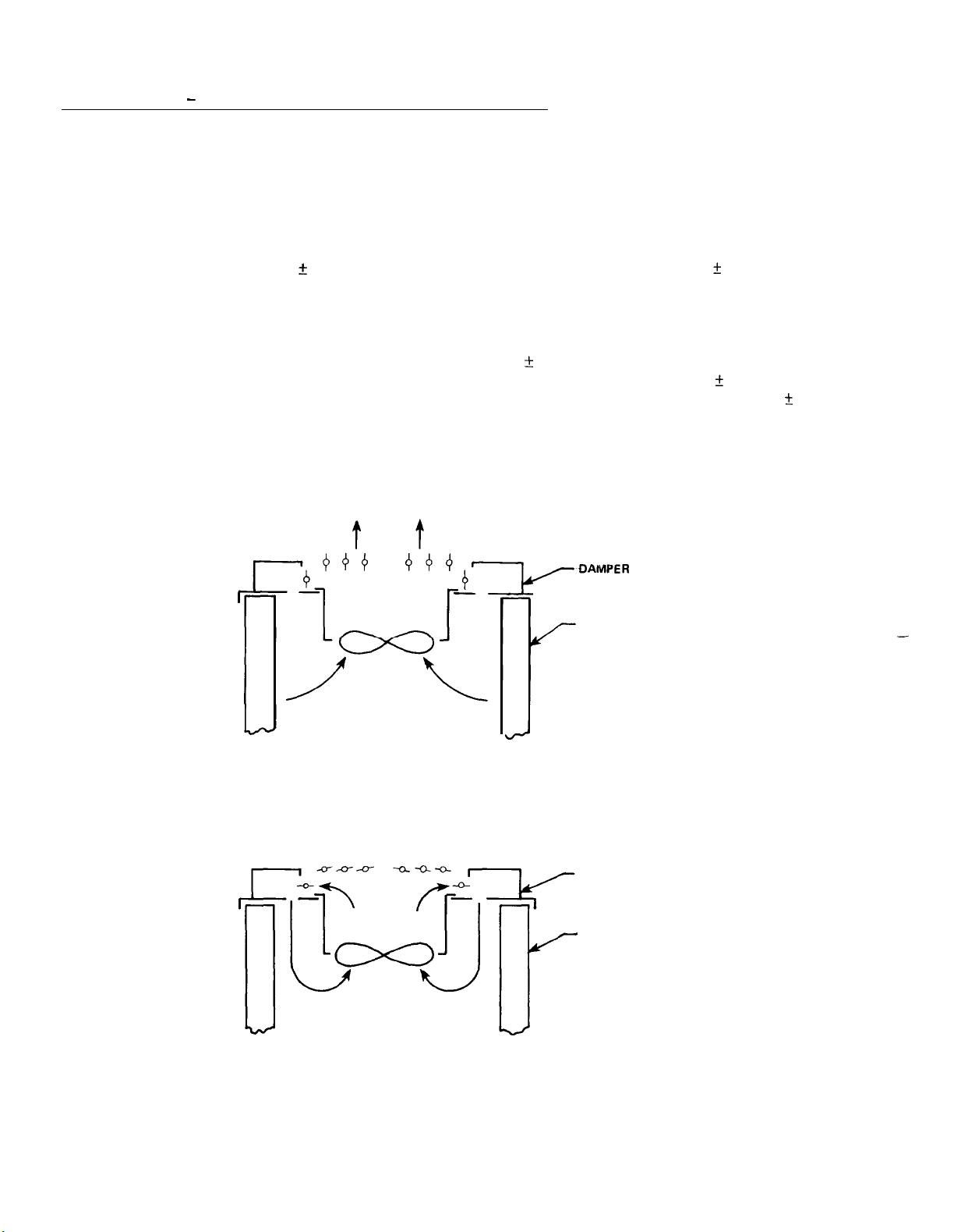
Dampertrol is an optional system for reducing condenser capacity. It
consists of an assembly of damper blades,
linkages and blade operators
installed over the first fan turned on by Fantrol (Fan No. 11) and
arranged to operate as shown.
The blade operators sense condenser
pressure and extend or contract in response to the pressure to open
or close the damper blades as required to maintain adequate conden-
ser pressure.
damper blades at 170
The operators are factory set to begin opening the
+
5 PSIG and to be fully open at 250 2 10 PSIG.
To check the damper blade operator pressure settings, the unit should
be started with the fuses removed from fans
only).
should be completely closed.
At condenser pressures below 170 & 5 PSIG, the damper blades
As pressure rises above 170
the damper blades should begin opening and be fully open at 250
10 PSIG.
Leaving the fuses in on fan 12 will prevent head pressure
11
and 13 (on 3 fan units
&
5 PSIG,
+_
from becoming excessive since this fan will start after the fully
open setting of the damper operators has been observed.
DAMPERTROL IN OPEN POSITION
rtz3qf
/DAMPER
SECTION
1
UNIT CONDENSER
/-
DAMPER SECTION
-
UNIT CONDENSER
page 46
DAMPERTROL IN CLOSED POSITION
Page 47

Part Winding Start
-
Optional
Part winding start is available on all voltage units and consists of
a solid state time delay wired in series with the contactor that ener-
gizes the 2nd winding of each compressor motor.
limit current in-rush to the compressors upon start up.
pressor starts,
the contactor for the first motor winding is energized
Its purpose is to
As each com-
instantly while that for the second motor winding is delayed for 1
second.
Control checkout is best accomplished by observation as each contac-
tor is pulled in to see that the 1 second delay occurs before the
second contactor pulls in.
LINE
PART WINDING
TIME DELAY
LINE
.-%..,
1
A-
COMPRESSOR CONTACTOR
(1st
MOTOR WINDING)
COMPRESSOR CONTACTOR
(2nd MOTOR WINDING)
NEUTRAL
NEUTRAL
Low Ambient Start - Optional
Low ambient start is available on all units as an option with Fantrol
and included automatically with optional Dampertrol.
It consists of
a solid state normally closed time delay wired in series with a relay.
These are both wired in parallel to the liquid line solenoid valve so
that when the solenoid valve is energized by the unit thermostat, the
low ambient start relay is also energized through the time delay.
The relay has contacts that essentially short circuit the low pres-
sure control and allow the compressor to start with the low pressure
control open.
After about 2
the relay.
to close the low pressure control,
3/4
minutes,
the time delay will open and de-energize
If the system has not built up enough evaporator pressure
the compressor will stop.
The
time delay can be reset to its original normally closed position by
moving the pumpdown
position.
Moving the pumpdown switch back to the "auto. pumpdown"
switch(es) (PSl
or PS2) to the "man. pumpdown"
position will again energize the relay for another attempt at start
up
.
If the system has built up enough evaporator pressure, the com-
pressor will continue to run.
To check the control,
wire(s) (No.
&
LP2) from terminal 4 in the unit control center.
113
&
213) leading to the low pressure control(s)
turn off all power to the unit and remove the
(LPl
Remove the com-
pressor fuses and jumper across terminals L & M of the freeze con-
trols(s) and oil pressure safety control(s).
Energize the control
circuit by turning on the control circuit disconnect or main power
disconnect (depending on the installation) and the control stop
switch
Sl.
The compressor contactors should pull in instantly.
page 47
Page 48

NOTE: Line is only hot when the unit thermostat calls for compressor to run.
Compressor Lockout - Optional
Compressor lockout consists of a solid state time delay wired in
series with the compressor contactor(
rapid compressor cycling when cooling demands are erratic.
Its purpose is to prevent
The cir-
cuit illustrated above is for the lead compressor in each refrigerand circuit.
The circuit for the second compressor(s) performs the
same function but is wired differently (see unit wiring diagram).
When the unit thermostat no longer calls for cooling and the com-
pressor contactor have opened,
the lockout time delay breaks open
the circuit preventing compressore re-start.
The circuit remains open for a period of 5 minutes so that if the
unit thermostat should call for cooling before the delay period has
expired,
the compressor will not re-start.
After 5 minutes, the
time delay will close its contacts to complete the circuit and be
ready for start up.
The time delay opens its contacts whenever power to terminal 4 is interrupted and resets closed automatically after the time delay period.
To check the control,
Move the pumpdown switch
tion.
Immediately after the compressor(s) have stopped running,
the compressor(s) must be running initially.
(PSl
or
PS2)
to the "man. pumpdown" posi-
move the pumpdown switch back to the "auto. pumpdown" position.
lead compressor should not re-start for 5 minutes.
The second com-
pressor in the refrigerant circuit should start approximately 20
seconds after the lead compressor,
high enough to require it.
Each refrigerant circuit can be checked
provided that the cooling load is
the same way.
LINE
(SEE NOTE)
NOTE:
Hot whenever freeze control and high
pressure control permit safe operation.
x-k-
-
’
’
COMF!
LOCKOUT
TIME DELAY
TO UNIT THERMOSTAT
The
page 48
Page 49

Alarm Bell - Optional
The 24 volt alarm bell is mounted inside the control center but not
wired to the control circuit.
the customer will want to relocate the bell where it will be more
easily heard in the event of a safety failure.
connection of the bell inside a junction box which is located in the
unit control center.
mounted in a preferred location and wired to the leads in the junc-
tion box.
The bell is wired into the control circuit so that it will sound
whenever there is a failure due to low oil pressure, motor overload,
or excessive condenser pressure.
All that is necessary is that the bell be
It is expected that in most cases,
There are leads for
Hot Gas Bypass
Hot gas bypass is a system for maintaining evaporator pressure at or
above a minimum value.
locity of the refrigerant as it passes through the evaporator high
enough for proper oil return to the compressor when cooling load con-
ditions are light.
The system usually consists of a solenoid valve piped in series with
a pressure regulating valve as shown. Units are available with op-
tional hot gas connection with a manual shutoff valve and capped stub.
A hot gas bypass kit consisting of a 115 volt solenoid valve and a
pressure regulating valve is available from McQuay under ordering
number 886-321262B-02 for ALP units 067AS/D through 159AD.
The solenoid valve should be wired to open whenever the unit
stat calls for the first stage of cooling (see Figure 10).
sure regulating valve that McQuay offers is factory set to begin
opening at 58 PSIG
an 80F ambient temperature.
long as it senses a fairly constant temperature at various load conditions.
It is generally in the 50F to 60F range.
that when the bulb is sensing 50F to 60F temperatures, the valve will
begin opening at 54 to 56 PSIG.
dicated above, by changing the pressure of the air charge in the
adjustable bulb.
the bulb and turn the adjustment screw clockwise.
ting,
beyond the range it is designed for as this will damage the adjustment assembly.
The compressor suction line is one such mounting location.
turn the screw counter-clockwise.
-
Optional
The purpose for doing this is to keep the ve-
(32F
for R-22) when the air charged bulb is in
The bulb can be mounted anywhere as
The chart on page 50 indicates
This setting can be changed as in-
To raise the pressure setting, remove the cap on
To lower the set-
Do not force the adjustment
thermo-
The pres-
The regulating valve opening point can be determined by slowly reduc-
ing the system load while observing the suction pressure.
bypass valve starts to open,
side of the valve will begin to feel warm to the touch.
CAUTION:
The hot gas line may become hot enough to cause injury in
a very short time so care should be taken during valve
checkout.
the refrigerant line on the evaporator
When the
page 49
Page 50

On installations where the condensing unit is remote from the evaporator,
it is recommended that the hot gas bypass valve be mounted near
the condensing unit to minimize the amount of refrigerant that will
condense in the hot gas line during periods when hot gas bypass is
not required.
The expansion valve,
quire replacement, but if it does,
using the manual liquid line shutoff valve.
traced to the power element only,
like the solenoid valve, should not normally re-
the unit must be pumped down by
If the problem can be
it can be unscrewed from the valve
body without removing the valve but only after pumping the unit down
with the manual liquid line shutoff valves.
HOT GAS BYPASS PIPING
Hot Gas Bypass
Solenoid Valve
L
Discharge
Line
Bypass Valve
DIAGRAM
r
SuctionsLine
Remote Bulb
External Equalizer
Connection to Suction
Side of Evapoator
Inlet After
Expansion Valve
;,
HOT GAS BYPASS ADJUSTMENT RANGE
REMOTE
BULB
ADJUSTMENT RANGE
a0
I I
I
TEMP
ioFI
I
I
AT BULB LOCATION
I
I
page 50
 Loading...