

Page 1
Page 2
TABLE OF CONTENTS
INTRODUCTION
General Description . . . . . . . . . . . . . . . . . . . . . . . . . ...3
Nomenclature . . . . . . . . . . . . . . . . . . . . . . . . . . . . . . ...3
Inspection . . . . . . . . . . . . . . . . . . . . . . . . . . . . . . . . . ...3
INSTALLATION
Handling . . . . . . . . . . . . . . . . . . . . . . . . . . . . . . . . . . ...3
Location . . . . . . . . . . . . . . . . . . . . . . . . . . . . . . . . . . . ...4
Service Access . . . . . . . . . . . . . . . . . . . . . . . . . . . . . ...4
Clearance Requirements . . . . . . . . . . . . . . . . . . . . . ...4
Vibration Isolators . . . . . . . . . . . . . . . . . . . . . . . . . ...4.5
REFRIGERANT PIPING
General . . . . . . . . . . . . . . . . . . . . . . . . . . . . . . . . . . . ...6
Recommended piping arrangements . . . . . . . . . . . . ...7
Refrigerant piping connections . . . . . . . . . . . . . . . . ...7
Recommended line sizes . . . . . . . . . . . . . . . . . . . . . ...8
Holding charge . . . . . . . . . . . . . . . . . . . . . . . . . . . . . ...8
Pressure testing . . . . . . . . . . . . . . . . . . . . . . . . . . . . ...8
Leak testing . . . . . . . . . . . . . . . . . . . . . . . . . . . . . . . . ...8
Evacuation . . . . . . . . . . . . . . . . . . . . . . . . . . . . . . . . . ...9
Charging the system . . . . . . . . . . . . . . . . . . . . . . . . . ...9
Hot gas bypass components.. . . . . . . . . . . . . . . . . ...9
Refrigerant charge . . . . . . . . . . . . . . . . . . . . . . . . . . ...9
Weight of refrigerant in copper lines.... . . . . . . . . ...9
Pressure-vacuum equivalents . . . . . . . . . . . . . . . . ...10
PHYSICAL DATA . . . . . . . . . . . . . . . . . . . . . . . . . ...10.11
DIMENSIONAL DATA . . . . . . . . . . . . . . . . . . . . . ...12.13
FIELD WIRING . . . . . . . . . . . . . . . . . . . . . . . . . . . ...14.15
Wire sizing ampacities . . . . . . . . . . . . . . . . . . . . . . ...16
Compressor and condenser fan motors . . . . . . . . ...17
Thermostat wiring and capacity reduction . . . ...17.18
Water piping for chilled water applications , . . . . . ...18
Flow switch for chilled water applications . . . . . . . ...18
Evaporator fan interlock
for air handler coil installations . . . . . . . . . . . . . ...19
UNIT LAYOUT&PRINCIPLES OFOPERATION
Major component locations . . . . . . . . . . . . . . . . . . ...19
Control center . . . . . . . . . . . . . . . . . . . . . . . . . . ...19.20
Electrical legend . . . . . . . . . . . . . . . . . . . . . . . . . . . ...21
Unit disconnect . . . . . . . . . . . . . . . . . . . . . . . . . . . . ...21
Sequence of operation . . . . . . . . . . . . . . . . . . . . . . ...22
TYPICAL WIRING SCHEMATICS
Power schematics . . . . . . . . . . . . . . . . . . . . . . . ...23-39
Control and safety schematics . . . . . . . . . . . . . ...40-42
Thermostat schematics, . . . . . . . . . . . . . . . . . . ...43-45
Wiring schematic decision tables.. . . . . . . . . . ...46.47
STARTUP&SHUTDOWN
Pre-startup . . . . . . . . . . . . . . . . . . . . . . . . . . . . . . . . ...48
Initial startup . . . . . . . . . . . . . . . . . . . . . . . . . . . . . . ...48
Temporary shutdown . . . . . . . . . . . . . . . . . . . . . . . . ...48
Startup after temporary shutdown . . . . . . . . . . . . . ...48
Extended shutdown . . . . . . . . . . . . . . . . . . . . . . . . . ...48
SYSTEM MAINTENANCE
General . . . . . . . . . . . . . . . . . . . . . . . . . . . . . . . . . . ...49
Fan shaft bearings . . . . . . . . . . . . . . . . . . . . . . . . . ...49
Electrical terminals . . . . . . . . . . . . . . . . . . . . . . . . . ...49
Compressor oil level . . . . . . . . . . . . . . . . . . . . . . . . ...49
Oil Equalization . . . . . . . . . . . . . . . . . . . . . . . . . . . . ...49
Condensers . . . . . . . . . . . . . . . . . . . . . . . . . . . . . . . ...49
Refrigerant sightglass . . . . . . . . . . . . . . . . . . . . . . . ...49
SERVICE
Filter-driers . . . . . . . . . . . . . . . . . . . . . . . . . . . . . . . . ...50
Liquid line solenoid valve . . . . . . . . . . . . . . . . . . . . ...50
Thermostatic expansion valve . . . . . . . . . . . . . . . . ...50
IN-WARRANTY RETURN MATERIAL PROCEDURE
Copeland compressor . . . . . . . . . . . . . . . . . . . . . . . ...51
Components other than compressors . . . . . . . . . . ...51
APPENDIX
Standard Contr61s:
Oil pressure safety control . . . . . . . . . . . . . . . . . . . ...51
High pressure control . . . . . . . . . . . . . . . . . . . . . . . ...52
Low pressure control . . . . . . . . . . . . . . . . . . . . . . . . ...52
FANTROL head pressure control . . . . . . . . . . . ...52.53
Compressor lockout . . . . . . . . . . . . . . . . . . . . . . . . ...53
Compressor motor protector . . . . . . . . . . . . . . . . . . ...53
Optional Controls:
SPEEDTROL head pressure control . . . . . . . . . . . ...54
Compressor unloaders . . . . . . . . . . . . . . . . . . . . . . ...54
Low ambient start . . . . . . . . . . . . . . . . . . . . . . . . . . ...54
High ambient unloader . . . . . . . . . . . . . . . . . . . . . . ...54
Part winding start . . . . . . . . . . . . . . . . . . . . . . . . . . ...54
Phase/voltagemonitor . . . . . . . . . . . . . . . . . . . . . . ...55
Hot gas bypass (field installed) . . . . . . . . . . . . . . . ...55
ALP controls, settings&functions . . . . . . . . . . ...56. 57
Troubleshooting chart . . . . . . . . . . . . . . . . . . . . ...58.59
Page2/lM269
“FanTrol”, “McC!uay”, “
of McQuay Air Conditioning, McOuay International, Minneapolis MN
G 1995 McOuay Air Conditioning. McQuaylnternational. Minneapolis. MN
“Bulletin illustrations cover the general appearance of Mc@ay International products al the time of publica! ior,
and we reserve the right to make changes in design and construction at any time without notice”
SeasonCon” and “SpeedTrol” are registered trademarks
Page 3
INTRODUCTION
GENERAL DESCRIPTION
McQuay type SeasonCon air cooled water condensing units
are designed for outdoor installations and are compatible with
either air handling or chilled water systems. Each unit is completely assembled and factory wired before evacuation, charging and testing, and comes complete and ready for installation. Each unit “consists of twin air cooled condensers with
integral subcooler sections, multiple accessible hermetic compressors, complete discharge piping and suction connections
for connection to any air or water cooling evaporator.
NOMENCLATURE
INSPECTION
When the equipment is received, all items should be careful-
Iy checked against the bill of lading to insure a complete shipment. All units should be carefully inspected for damage upon
arrival. All shipping damage should be reported to the car-
rier and a claim should
be filed. The unit serial plate should
The electrical control center includes all safety and operating controls necessary for dependable automatic operation
except for the cooling thermostat since this is somewhat
dependent on the unit application. Condenser fan motors are
fused in all three conductor legs and started by their own
three-pole contractors. Compressors are not fused but may
be protected by optional circuit breakers, or by field installed
fused disconnect.
be checked before unloading the unit to be sure that it agrees
with the power supply available. Physical damage to unit after
acceptance is not the responsibility of McQuay.
NOTE: Unit shipping and operating weights are available
in the physical data tables on pages 10 and 11.
INSTALLATION
NOTE: Installation and maintenance are to be performed only by qualified personnel who are familiar with local codes
and regulations, and experienced with this type of equipment.
CAUTION: Sharp edges and coil surfaces are a potential injury hazard. Avoid contact with them.
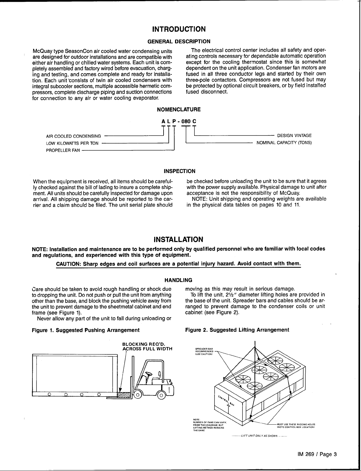
HANDLING
Care should be taken to avoid rough handling or shock due
to dropping the unit. Do not push or pull the unit from anything
other than the base, and block the pushing vehicle away from
the unit to prevent damage to the sheetmetal cabinet and end
frame (see Figure 1).
Never allow any part of the unit to fall during unloading or
Figure 1. Suggested Pushing Arrangement
BLOCKING REQ’D.
ACROSS FULL WIDTH
moving as this may result in serious damage.
To lift the unit, 21/2” diameter lifting holes are provided in
the base of the unit. Spreader bars and cables should be arranged to prevent damage to the condenser coils or unit
cabinet (see Figure 2).
Figure 2. Suggested Lifting Arrangement
,,,,,.,, 8,,
FIECOMMENWO
(uSE CAUTION)
MO,,
NUMBER 0, F..%
FROM, H,SO,A. R
U,,(NC METHOD R, MA, NS
THE SAME
LIFT UNIT OWL Y AS SHOWN
(NOTE .0.,,0, 80., ’0,.,,0.,
IM 269 I Page 3
HOLES
Page 4
LOCATION
Care should be taken in the location of the unit to provide
proper airflow to the condenser, minimizing effects on condensing pressure.
Due to the vertical condenser design of the ALP-120 thru
230 chillers, it is recommended that the unit is oriented so
that prevailing winds blow parallel to the unit length, thus
minimizing the effects on condensing pressure, If it is not practical to orient the unit in this manner, a wind deflector should
be constructed.
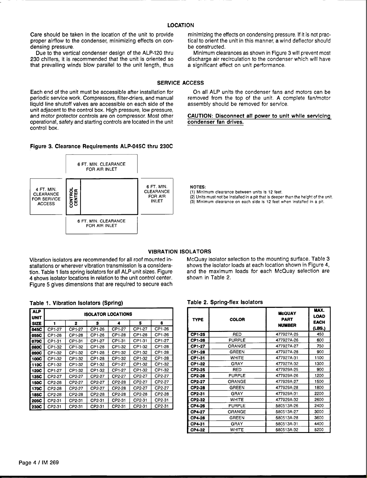
Minimum clearances as shown in Figure 3 will prevent most
discharge air recirculation to the condenser which will have
a significant effect on unit performance,
SERVICE
Each end of the unit must be accessible after installation for
periodic service work. Compressors, filter-driers, and manual
liquid line shutoff valves are accessible on each side of the
unit adjacent to the control box. High pressure, low pressure,
and motor protector controls are on compressor. Most other
operational, safety and starting controls are located in the unit
control box.
Figure 3. Clearance Requirements ALP-045C thru 230C
6 !7. MIN. CLEARANCE
4 FT. MIN.
CLEARANCE au
FOR SERVICE
ACCESS
I
1
FOR AIR INLET
da
i-~
~ti
I
6 FT. MIN. CLEARANCE
FOR AIR INLET
I
6 FT. MIN.
CLEARANCE
1
FOR AIR
INLET
VIBRATION
Vibration isolators are recommended for all roof mounted installations or wherever vibration transmission is a consideration. Table 1 lists spring isolators for all ALP unit sizes. Figure
4 shows isolator locations in relation to the unit control center.
Figure 5 gives dimensions that are required to secure each
ACCESS
On all ALP units the condenser fans and motors can be
removed from the top of the unit. A complete fan/motor
assembly should be removed for service.
CAUTION: Disconnect all power to unit while servicing
condenser fan drives.
NOTES:
(1)Minimum clearance between units is 12 feet,
(2) Units must not be installed in a pit that is deeper than the height of the unit
(3) Minimum clearance on
each side is 12 feet when installed in a pit.
ISOLATORS
McQuay isolator selection to the mounting surface. Table 3
shows the isolator loads at each location shown in Figure 4,
and the maximum loads for each McQuay selection are
shown in Table 2.
Table 1. Vibration Isolators (Spring)
ISOLATOR LOCATIONS
SUE
045C CP
055c CP
t=!=
------ ..-— — ——, .
Cl CPI.!17 I CP1.W I CP1-28 I CP1-32 I CP1-32 I CF
Iooc,-..-.,- .. --,-..--, ----, - -11OCICP1-32
120C I CP1-27
~ CP2-27
Page 4 I IM 269
CP1-32 CPI-32
CP1-32
CP2-27
CP1-32
CP2-27 CP2-27
CP1-27
CP1-27 CPI-32 CPI-32
CPI-32
CP2-27 CP2-27
‘1-28
CP1-32
Table 2. Spring-flex Isolators
TYPE COLOR
P+.25 RED 4n927A-25
----
tiP1-26
1
CP1-27 ORANGE
CP1-28
I
CP1-31
CPI-32
CP2-25
I
CP2-28
CP2-27
CP2-28
-.
--
CP4-27
I
CP4-28
CP4-31
I
CP4-32 WHITE 580513A-32
i=
I
I
I
I
I
1
MAX.
LOAD
EACN
0-=.)
2200
2400
3000
4400
5200
McOUAY
PART
NUMBER
PURPLE
GREEN
WHITE
GRAY
RED
PURPLE
ORANGE
GREEN
ORANGE
GREEN 58051 3A-26 3600
GRAY
477927A-26
I
477927A-27
477927A-26
I
4n927A-31 1100
4n927A-32
4n929A-25 900
477929A-26
4n929A-27
477929A-26
4n929A-31
4n929A-32 2600
580513A-26
58051 3A-27
I
58051 3A-31
I
450
600
750
900
1300
1200
1500
1800
Page 5
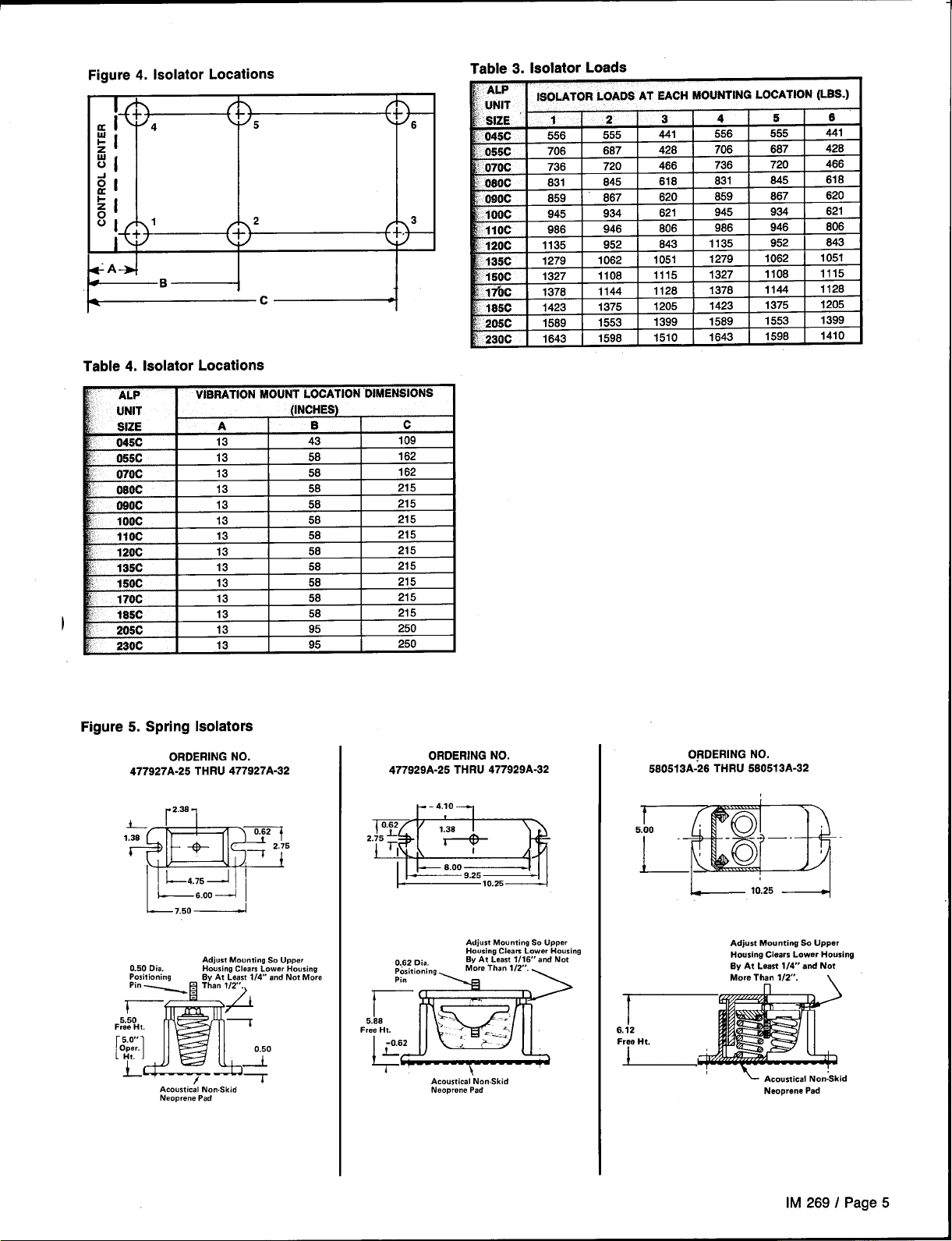
Figure 4. Isolator Locations
Table 4. Isolator Locations
—c—
1-
6
3
>
Table 3. Isolator 1m=~=
ALP
? UNIT
SIZE 1
: 045C
055C
~ 070C
Osoc
‘ 090C
100C
‘ 11OC
120C
, 135C
, 150C
wbc
185C
: 205C
230C
ISOLATOR LOADS AT SACH FAOUNTING LOCATION (l-SS.)
.“”””
556
706
736
831
859 867
945
986
1135
1279
1327
1376
1423
1569
1643
2
555
687
720
845
934
946
952
1062
1108
1144
1375
1553
1596
3
441
428
466
618
~]
621
806
643
1051
1115
1128
1205
1399
1510
4
556
706
736
631
659
945
986
1135
1279
1327
1378
1423
1569
1643
5
555
687
720
845
867
934
I
946
952
1062
1108
1144
1375
1553
1598
6
441
426
466
618
620
621
806
643
1051
1115
1128
1205
1399
1410
I
I
VIBRATION MOUNT LOCATION DIMENSIONS
Figure5. Spring Isolators
ORDERING NO.
477927A-26 THRU 477927A-32
(INCHES)
ORDERING NO.
477929A-25 THRU 477929A-32
ORDERING NO.
580513A-26 THRU 580513A-32
Ls.oo --- I
1-
7,,0 ~
0,50 Dia.
Positioning
Acoustical No..Skid
Neoprene Pad
Adjust Mounting So Upper
Housing Clears Lower HousinQ
By At Least IW and Not More
2“%Ezili
6
F
Acoustical No..Skid
Neoprene Pad
_ 10.25 .—~
Adjust Mounting so Upper
Housing Clears Lower Housing
By At Least 114” and Not
More Than 1/2”.
~ Acoustical Non:Skid
Neoprene Pad
\
IM 269/ Page 5
Page 6
REFRIGERANT
PIPING
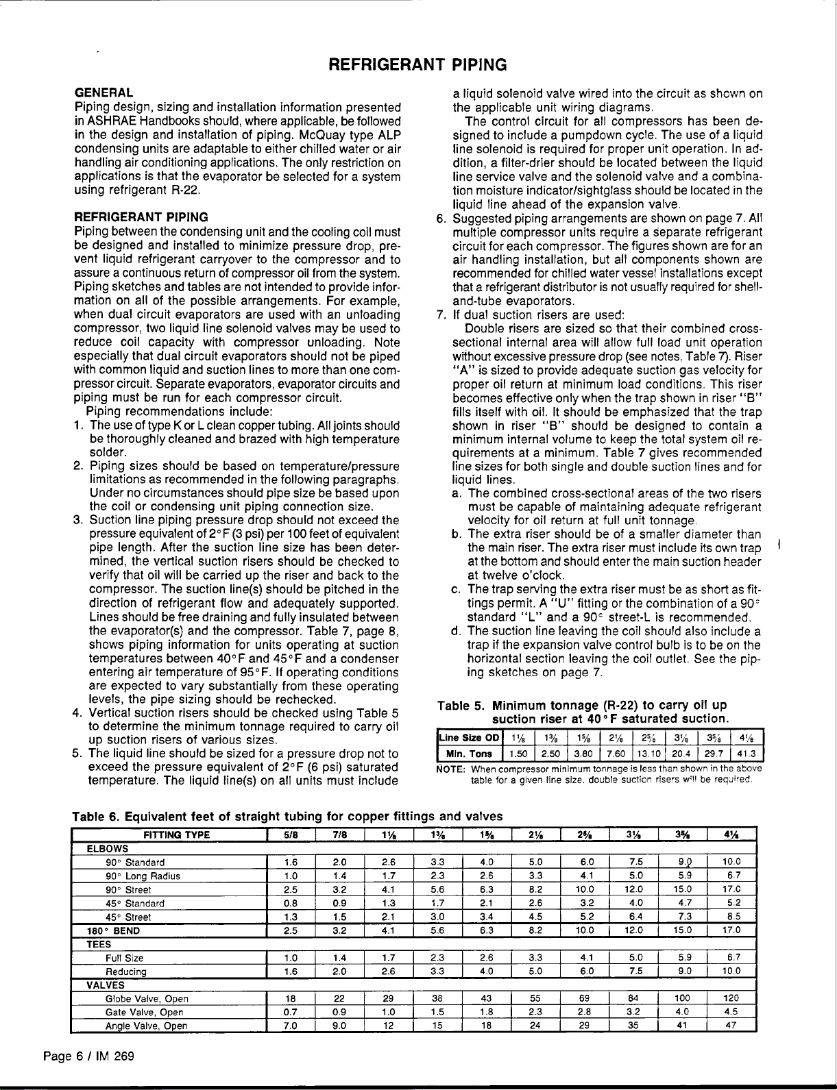
GENERAL
Piping design, sizing and installation information presented
in ASHRAE Handbooks should, where applicable, be followed
in the design and installation of piping. McQuay type ALP
condensing units are adaptable to either chilled water or air
handling air conditioning applications, The only restriction on
applications is that the evaporator be selected for a system
using refrigerant R-22.
REFRIGERANT PIPING
Piping between the condensing unit and the cooling coil must
be designed and installed to minimize pressure drop, prevent liquid refrigerant carryover to the compressor and to
assure a continuous return of compressor oil from the system.
Piping sketches and tables are not intended to provide information on all of the possible arrangements. For example,
when dual circuit evaporators are used with an unloading
compressor, two liquid line solenoid valves may be used to
reduce coil capacity with compressor unloading. Note
especially that dual circuit evaporators should not be piped
with common liquid and suction lines to more than one compressor circuit. Separate evaporators, evaporator circuits and
piping must be run for each compressor circuit.
Piping recommendations include:
The use of type K or L clean copper tubing. All joints should
1.
be thoroughly cleaned and brazed with high temperature
solder.
2.
Piping sizes should be based on temperature/pressure
limitations as recommended in the following paragraphs,
Under no circumstances should pipe size be based upon
the coil or condensing unit piping connection size.
Suction line piping pressure drop should not exceed the
3.
pressure equivalent of 2° F (3 psi) per 100 feet of equivalent
pipe length. After the suction line size has been determined, the vertical suction risers should be checked to
verify that oil will be carried up the riser and back to the
compressor. The suction line(s) should be pitched in the
direction of refrigerant flow and adequately supported.
Lines should be free draining and fully insulated between
the evaporator(s) and the compressor. Table 7, page 8,
shows piping information for units operating at suction
temperatures between 40F and 45 F and a condenser
entering air temperature of 95F. If operating conditions
are expected to vary substantially from these operating
levels, the pipe sizing should be rechecked.
Vertical suction risers should be checked using Table 5
4.
to determine the minimum tonnage required to carry oil
up suction risers of various sizes:
5. The liquid line should be sized for a pressure drop not to
exceed the pressure equivalent of 2° F (6 psi) saturated
temperature. The liquid line(s) on all units must include
a liquid solenoid valve wired into the circuit as shown on
the applicable unit wiring diagrams.
The control circuit for all compressors has been designed to include a pumpdown cycle. The use of a liquid
line solenoid is required for proper unit operation. In addition, a filter-drier should be located between the liquid
line service valve and the solenoid valve and a combination moisture indicator/sightglass should be located in the
liquid line ahead of the expansion valve.
6.
Suggested piping arrangements are shown on page 7. All
multiple compressor units require a separate refrigerant
circuit for each compressor. The figures shown are for an
air handling installation, but all components shown are
recommended for chilled water vessel installations except
that a refrigerant distributor is not usually required for shell
and-tube evaporators.
7.
If dual suction risers are used:
Double risers are sized so that their combined crosssectional internal area will allow full load unit operation
without excessive pressure drop (see notes, Table 7). Riser
“A” is sized to provide adequate suction gas velocity for
proper oil return at minimum load conditions, This riser
becomes effective only when the trap shown in riser “B”
fills itself with oil. It should be emphasized that the trap
shown in riser “B” should be designed to contain a
minimum internal volume to keep the total system oil requirements at a minimum. Table 7 gives recommended
line sizes for both single and double suction lines and for
liquid lines.
The combined cross-sectional areas of the two risers
a.
must be capable of maintaining adequate refrigerant
velocity for oil return at full unit tonnage,
The extra riser should be of a smaller diameter than
b.
the main riser. The extra riser must include its own trap
at the bottom and should enter the main suction header
at twelve o’clock.
The trap serving the extra riser must be as short as fit-
c.
tings permit. A “U” fitting or the combination of a 90’
standard “L” and a 90C street-L is recommended,
The suction line leaving the coil should also include a
d.
trap if the expansion valve control bulb is to be on the
horizontal section leaving the coil outlet, See the piping sketches on page 7.
Table 5. Minimum tonnage (R-22) to carry oil up
suction riser at 400 F saturated suction.
Min. Tons
NOTE: When compressor minimum tonnage is less than shown in the above
1.50 2.50 3.80 7.60 13.10 204 29.7 41.3
table for a given line size. double suction risers will be required
I
Table 6. Equivalent feet of straight tubing for copper fittings and valves
I
I
I 90” Lono Radius I 1.0 I
.“-
TEES
VALVES
FITTING TYPE
90” Standard
90” Street
45” Standard
A6. .Wrss! 13 15 91 30
-h, .-
Full Size
Reducing
Globe Valve, Open
Gate Valve, Open 0.7
Angle Valve, Open 7.0 9.0
518
I
1.6 2.0
!
2.5 3.2 4.1
0.8 0.9
-.”
1
1.0
I
1.6 2.0
18 22 29
718 1%
2.6 3.3 4.0 5.0 6.0
1.4 I 1.7
“.-
1
1
1.4 1.7 2.3 2.6 3.3
0.9
I 2.3 I 2.6 I 3.
1,3
.,.
1
2.6 3.3 4.0 5.0 6.0
1.0
12
Page 6 I IM 269
1yf 1V*
5.6
1.7
---
38 43 55 69 84
1.5
15 18 24 29 35
6.3
2.1 2.6 3.2
34 45 57 64 7.3 I 85
---
1
1.8 2.3 2.8 3.2
2y* 2%
I
3
8.2
---
1
4.1 5.0 5.9 6.7
10.0 12.0 15.0 17.C
..- ----
,
4.1 5.0 5.9 6.7
31/s 3%
7.5 9.9
4.0
.-. .
!
7.5 9.0
100 120
4.0 4.5
41~
10.0
4.7
10.0
41 47
[
52
..-
Page 7
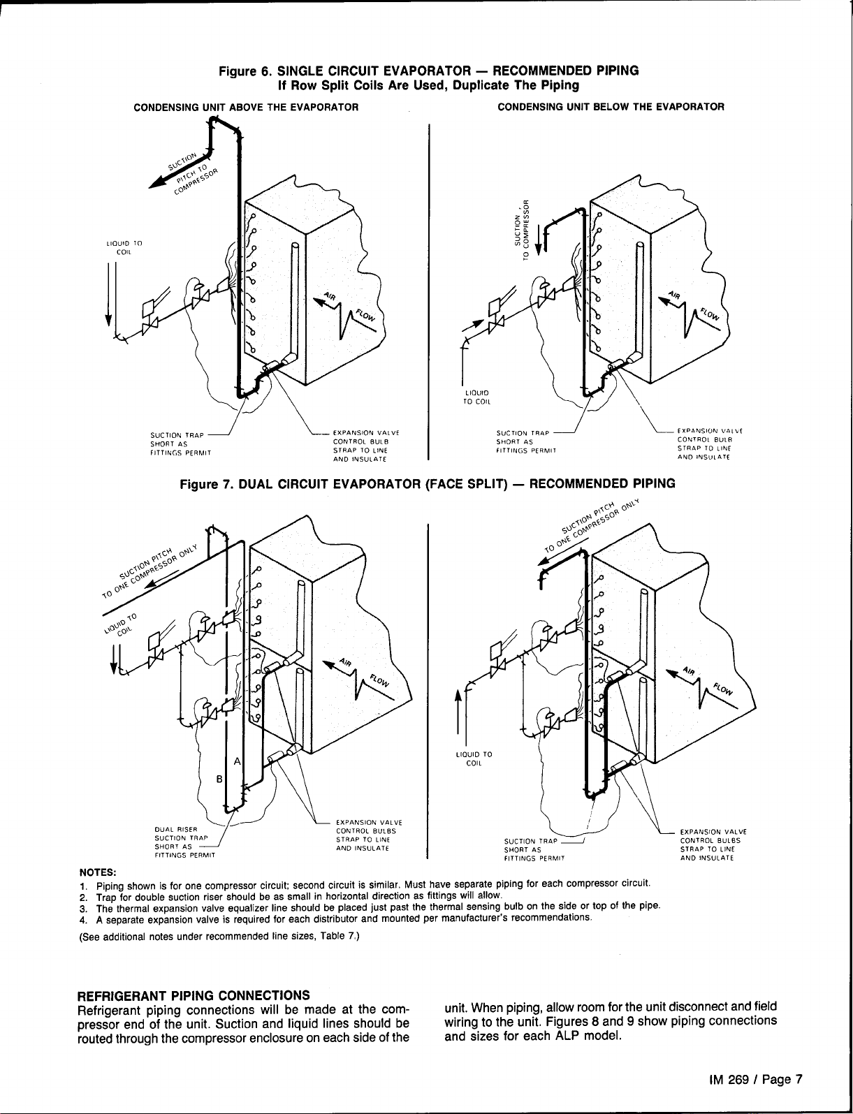
Figure 6. SINGLE CIRCUIT EVAPORATOR – RECOMMENDED PIPING
If Row Split Coils Are Used, Duplicate The Piping
CONDENSING UNIT AaOVE THE EVAPORATOR
CONDENSING UNIT BELOW THE EVAPORATOR
LlOU10
TO COIL
“L___
SUCTION TRAP
SHORT AS
FITTINGS PERMIT
1
EXPANSION VALVE
CONTROL BULB
STRAP TO LINE
AND lNSUIATf
SUCTION TRAP ~
SHORT AS
FITTINGS PERMIT
Figure 7. DUAL CIRCUIT EVAPORATOR (FACE SPLIT) – RECOMMENDED PIPING
t
L(
SUCTION TRAP ~
SHORT AS
FITTINGS PERMIT
NOTES:
1. Piping shown is for one compressor circuit; second circuit is similar. Must have separate piping for each compressor circuit.
2. Trap for double suction riser should be as small in horizontal direction as fittings will allow.
3. The thermal expansion valve equalizer line should be placed just past the thermal sensing bulb on the side or top of the pipe.
4. A separate expansion valve is required for each distributor and mounted per manufacturer’s recommendations.
(See additional notes under recommended line sizes, Table 7)
L CXP4NSION VA1bl
CONTROL BULR
5TRAP To LINE
AND INSULATE
ION vALVE
CONTROL BuLBS
STRAP TO LINE
AND INSULATE
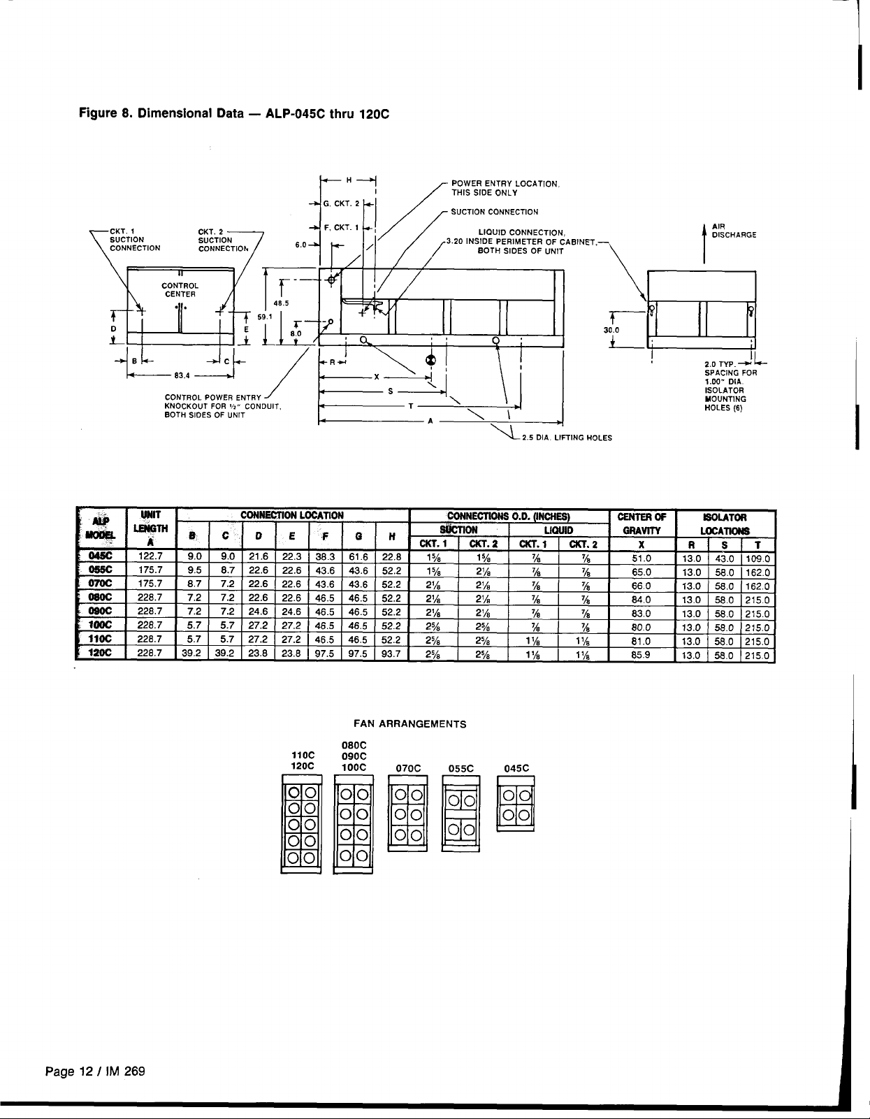
REFRIGERANT PIPING CONNECTIONS
Refrigerant piping connections will be made at the com-
pressor end of the unit. Suction and liquid lines should be
routed through the compressor enclosure on each side of the
unit. When piping, allow room for the unit disconnect and field
wiring to the unit. Figures 8 and 9 show piping connections
and sizes for each ALP model.
IM 269 I Page 7
Page 8
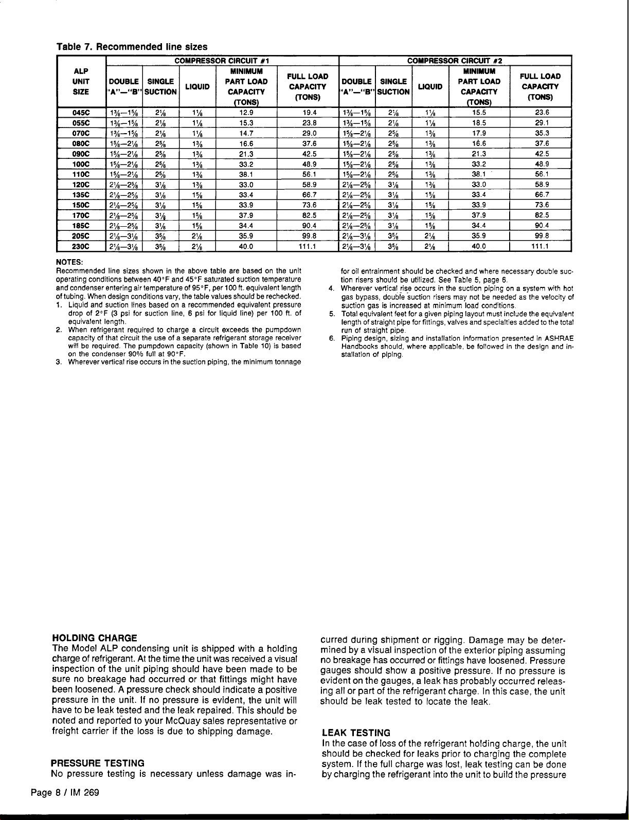
Table 7. Recommended line sizes
COMPRESSOR CIRCUIT #1
ALP
UNIT
SIZE
055C 13&15h
070C
080C
090C
100C 15/&2~h
11OC
120C 2%J—25/8
135C 27+2Y8 3X?
150C
DOUBLE
.A9*_,4
1%-1 ye
1%-15h
15h—21A
I
5~—2y8
15y&2y3
214—25A
170C 21h—25h
1MC 27’s-2y8 31~
205C 21&31~ 3%
230C
NOTES:
Recommended line sizes shown in the above table are based on the unit
operating conditions between 40F and 45 F saturated suction temperature
and condenser entering air temperature of 95F, per 100 ft. equivalent length 4.
of tubing. When design conditions vary, the table values should be rechecked.
1. Liquid and suction lines based on a recommended equivalent pressure
drop of 2F (3 psi for suction line, 6 psi for liquid line) per 100 ft. of
equivalent length,
2. When refrigerant required to charge a circuit exceeds the pumpdown
capacity of that circuit the use of a separate refrigerant storage receiver
will be required. The pumpdown capacity (shown in Table 10) is based
on the condenser 90% full at 90” F.
3. Wherever vertical rise occurs in the suction piping, the minimum tonnage
2%-31~
SINGLE
slJ~*,oN LIQulD
~,,
21h
z~~ 1% 15.3
21A
278
278
25~ 13~
2% 13~
37h 1ye 33.0 58.9
31~
31~
3%
11A
1% 14.7
1ah 16.6 37.6
1ye 21.3
1ye 33.4 66.7
1ye 33.9 73.6 2%-2Y8
1ya 37.9 82.5
1ye 34.4 90.4
21A 35.9
21A 40.0
MINIMUM
PART LOAD
CAPACITY
(TONS)
12.9 19.4
33.2
38.1
FULL LOAD
CAPACITY
(TONS)
23.8
29.0 15/’-21h
42.5 15/+2~h
48.9
56.1
99.8 21/&31~
111.1
COMPRESSOR CIRCUIT #2
DOUBLE SINGLE
,A,9_”
B“ SUCTION
1y&l
5/4
1y&l ya
15/*-21h
1y~—zl~
1y*—21h
2J&278
2J/4-25/a 3%
21&2y~ 37h
21A—25A 3Ys
21&31/s
fer oil entrainment should be checked and where necessary double suction rlsers should be utilized. See Table 5, page 6,
Wherever vertical rise occurs in the suction piping on a system with hot
gas bypass, double suction risers may not be needed as the velocity of
suction gas is increased at minimum load condtions.
Total equivalent feet for a given piping layout must include the equivalent
5
length of straight pipe for fittings, valves and specialties added to the total
run of straight pipe.
Piping design, sizing and installation information presented in ASHRAE
6
Handbooks should, where applicable, be followed in the design and
stallation of piping.
‘QU’D
214 11A 15.5 23.6
21A 11A 18.5 29.1
2% 1ya 17.9 35.3
2% 1Y* 16.6 37.6
2% 1ye 21.3
278 13h X3.2 48.9
278 1ye 38.7 56.1
31A 1ya 33.0 58.9
3%
35h 21A
35h
1ya 33.4 66.7
15~ 339 73.6
1y’ 37.9 82.5
15h 34.4 904
21A
.... .... . ... I I
mlnlmum
PART LOAD
-. -.-—..
GAPAUI I Y
m-)
35.9 998
40.0 111.1
FULL LOAD
CAPACITY
I
(TONS)
42.5
I
in-
HOLDING CHARGE
The Model ALP condensing unit is shipped with a holding
charge of refrigerant. At the time the unit was received a visual
inspection of the unit piping should have been made to be
sure no breakage had occurred or that fittings might have
been loosened. A pressure check should indicate a positive
pressure in the unit. If no pressure is evident, the unit will
have to be leak tested and the leak repaired. This should be
noted and reported to your McQuay sales representative or
freight carrier if the loss is due to shipping damage.
PRESSURE TESTING
No pressure testing is necessary unless damage was in-
Page 8 / IM 269
curred during shipment or rigging, Damage may be determined by a visual inspection of the exterior piping assuming
no breakage has occurred or fittings have loosened, Pressure
gauges should show a positive pressure. If no pressure is
evident on the gauges, a leak has probably occurred releas-
ing all or part of the refrigerant charge, In this case, the unit
should be leak tested to locate the leak.
LEAK TESTING
In the case of loss of the refrigerant holding charge, the unit
should be checked for leaks prior to charging the complete
system. If the full charge was lost, leak testing can be done
by charging the refrigerant into the unit to build the pressure
Page 9
to approximately 10 psig and adding sufficient dry nitrogen
to bring the pressure to a maximum of 125 psig. The unit
should then be leak tested with a Halide or electronic leak
detector. After making any necessary repair, the system should
be evacuated as described in the following paragraphs.
CAUTION: Do not use oxygen to build up pressure. A
serious explosion could be the result.
EVACUATION
After it has been determined that the unit is tight and there
are no refrigerant leaks, the system should be evacuated. The
use of a vacuum pump with a pumping capacity of approximately 3 cu. ft./min, and the ability to reduce the vacuum
in the unit to at least 1 millimeter (1000 microns) is recommended.
A mercury manometer, electronic or other type of micron
1.
gauge should be connected to the unit at a point remote
from the vacuum pump, For readings below 1 millimeter,
an electronic or other micron gauge should be used.
The triple evacuation method is recommended and is par-
2.
ticularly helpful if the vacuum pump is unable to obtain
the desired 1 millimeter of vacuum. The system is first
evacuated to approximately 29 inches of mercury. Enough
refrigerant vapor is then added to the system to bring the
pressure up to O pounds.
Then the system is once again evacuated to 29 inches of
3.
vacuum. This procedure is repeated three times. This
method can be most effective by holding system pressure
at Opounds for a minimum of 1 hour between evacuations.
The first pull down will remove about 90% of the noncondensibles, the second about 90%0 of that remaining
from the first pull down and after the third only 1/10 of 10%
non-condensibles will remain.
Table 12, page 10, shows the relationship between pressure,
microns, atmospheres, and the boiling point of water.
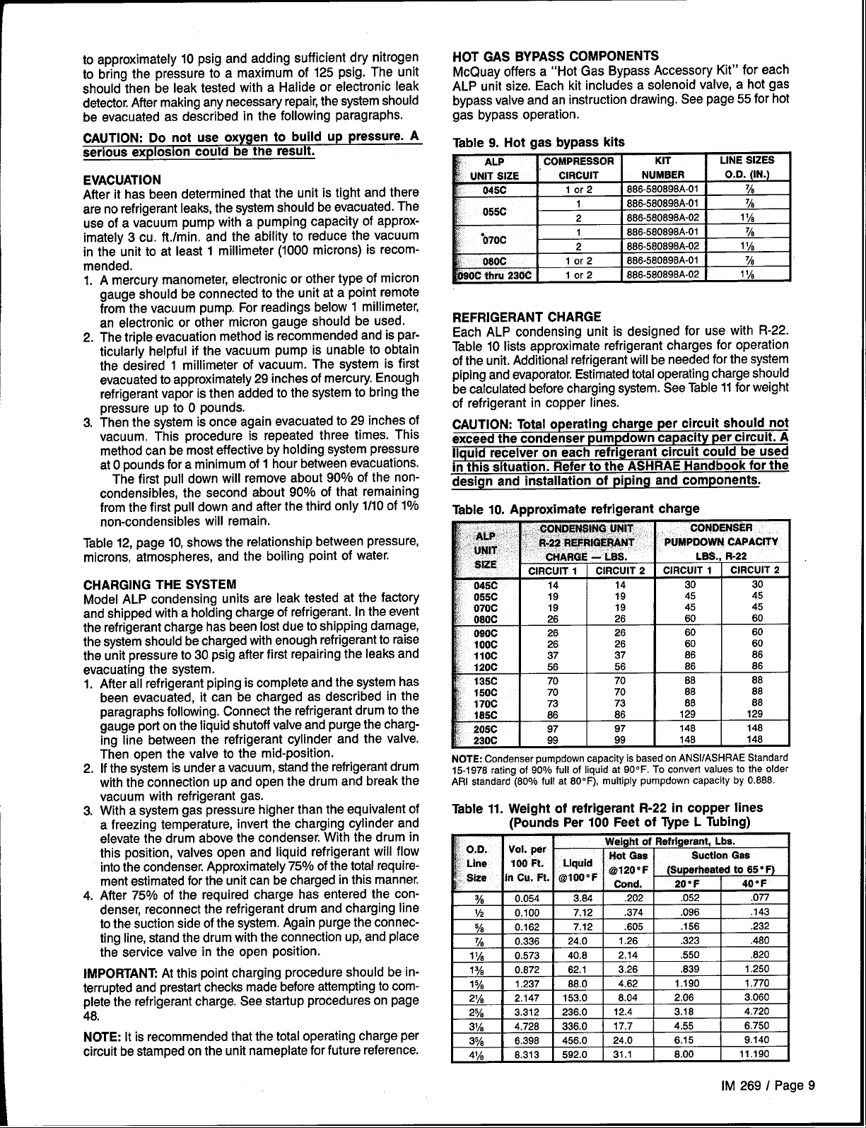
HOT GAS BYPASS COMPONENTS
McQuay offers a “Hot Gas Bypass Accessory Kit” for each
ALP unit size. Each kit includes a solenoid valve, a hot gas
bypass valve and an instruction drawing. See page 55 for hot
gas bypass operation.
Table 9. Hot gas bypass kits
COMPRESSOR
KIT
S86-580698A-01
866-580898A-01
886-580698A-02
886-5S0898A-01
886-5S0698A-02
886-580898A-01
886-580896A-02
LINE SIZES
%
~8
1IA
%
1*A
%
11A
REFRIGERANT CHARGE
Each ALP condensing unit is designed for use with R-22.
Table 10 lists approximate refrigerant charges for operation
of the unit. Additional refrigerant will be needed for the system
piping and evaporator. Estimated total operating charge should
be calculated before charging system. See Table 11 for weight
of refrigerant in copper lines.
CAUTION: Total operating charge per circuit should not
exceed the condenser pumpdown capacity
per circuit. A
liquid receiver on each refrigerant circuit could be used
in this situation. Refer to the ASHRAE Handbook for the
design and installation of piping and components.
Table 10. Approximate refrigerant charge
CHARGING THE SYSTEM
Model ALP condensing units are leak tested at the factory
and shipped with a holding charge of refrigerant. In the event
the refrigerant charge has been lost due to shipping damage,
the system should be charged with enough refrigerant to raise
the unit pressure to 30 psig after first repairing the leaks and
evacuating the system.
After all refrigerant piping is complete and the system has
1.
been evacuated, it can be charged as described in the
paragraphs following. Connect the refrigerant drum to the
gauge port on the liquid shutoff valve and purge the charging line between the refrigerant cylinder and the valve.
Then open the valve to the mid-position.
2,
If the system is under a vacuum, stand the refrigerant drum
with the connection up and open the drum and break the
vacuum with refrigerant gas.
With a system gas pressure higher than the equivalent of
3.
a freezing temperature, invert the charging cylinder and
elevate the drum above the condenser, With the drum in
this position, valves open and liquid refrigerant will flow
into the condenser. Approximately 75% of the total requirement estimated for the unit can be charged in this manner.
After 75% of the required charge has entered the con-
4.
denser, reconnect the refrigerant drum and charging line
to the suction side of the system. Again purge the connecting line, stand the drum with the connection up, and place
the service valve in the open position.
IMPORTANT At this point charging procedure should be interrupted and prestart checks made before attempting to complete the refrigerant charge. See startup procedures on page
48.
NOTE: It is recommended that the total operating charge per
circuit be stamped on the unit nameplate for future reference.
146
45
45
60
60
60
.-JC
070C
080C
090C
1Ooc
230C
NOTE: Condenser pumpdown capacity is based on ANS1/ASHRAE Standard
15-1976 rating of 90°/0 full of liquid at 900F. To convert values to the older
ARI standard (80% full at 800 F), multiply pumpdown capacity by 0,888.
19 19 45
19 19 45
26 26
26 26 60
26 28
99 99
I
60
60
148
I
Table 11. Weight of refrigerant R-22 in copper lines
(Pounds Per 100 Feet of Type L Tubing)
Weight of Refrigerant, Lba.
0.054 3.84
%
0.100
112
0.162 7.12 .605 .156
%
0.336 24,0 1.26 .323
%
11A 0.573 40.8
1% 0.872
1% 1.237 88.0
2~~ 2.147
25/8 3.312
31~
3% 6.398
4% 8.313 592.0 31.1 8.00
4.728 336.0 17.7 4.55 6.750
7.12 .374 .096
62.1
153,0
236.0 12.4 3.18 4.720
456.0 24.0 6.15 9.140
.202
2.14
3.26 .839
4.62 1.190 1.770
8.04
. . —.
Suction Gee
(Superheated to 65” F)
.052
.550
2,06 3.060
.077
.143
.232
.480
.620
1.250
11.190
I
IM 269 I Page 9
Page 10
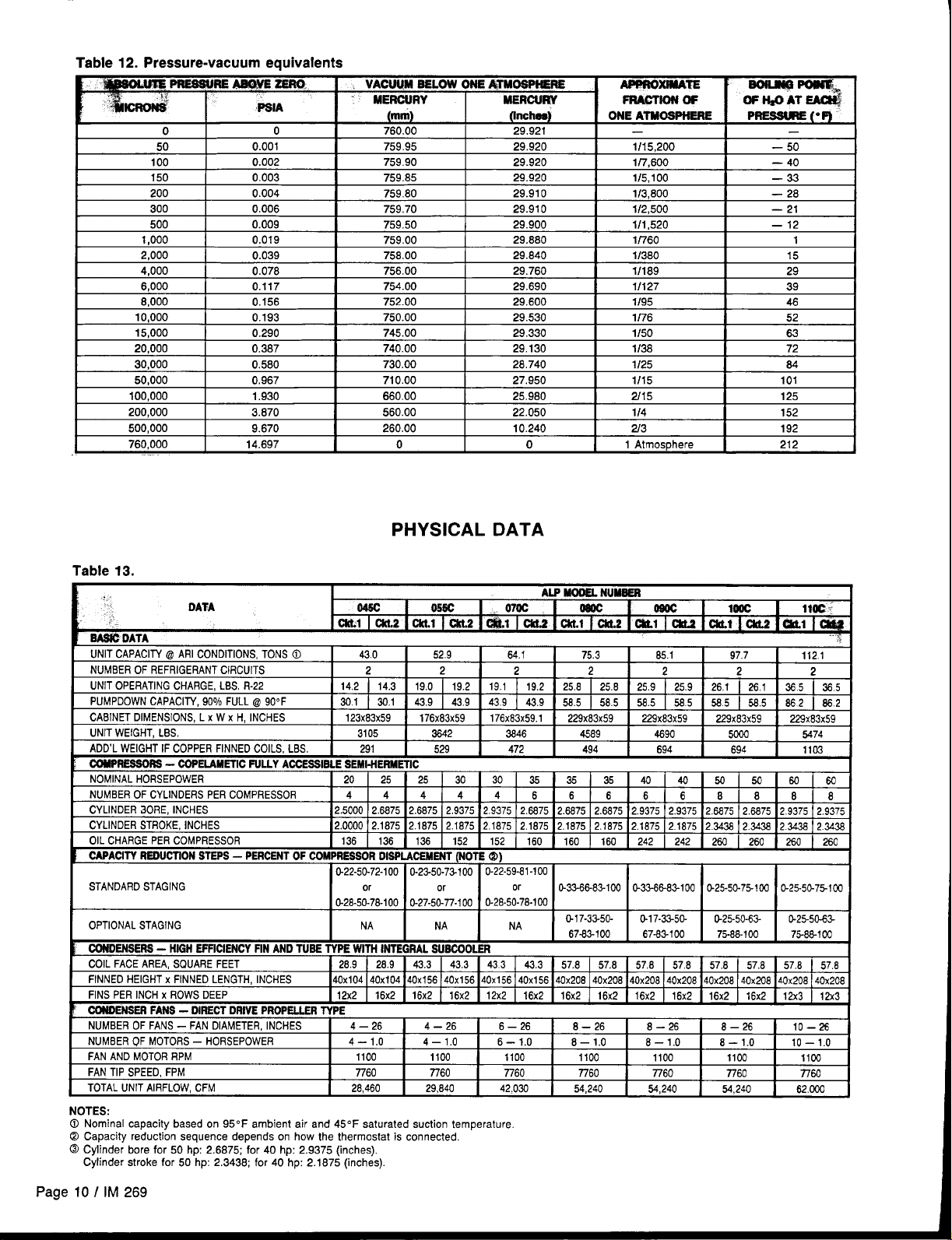
Table 12. Pressure-vacuum equivalents
o
50
100
150
200
300
500
1,000 0.019 759.00
2,000 0.039
4,000 0.078
6,000
8,000 0.156
10,000 0.193
15,000 0.290 745.00 29.330
20,000 0.387
30,000
50,000 0.967
100,000
200,000 3.670 560.00 22.050
600,000
760,000 14.697 0
0 760,00 29.921
0.001 759.95 29.920
0.002
0.003
0.004
0.006 759.70 29.910
0.009
0.117 754.00 29.690
0.580
1.930 860.00 25.980
9.670 260.00 10.240
759.90
759.85
759.80
759.50 29.900
758.00 29.840
756.00 29.760
752.00 29,600
750.00
740.00 29.130
730,00
710.00 27.950
29.920
29.920 1/5,100 —33
29.910
29.880
29.530
28.740
0
PHYSICAL DATA
— —
1/15,200
1/7,600 — 40
1/3,600
1/2,500 — 21
1/1 ,520 — 12
1/760 1
1/380 15
1/189
1/127
1/95
1/76
1/50
1138 72
1125 84
1/15 101
2/1 5 125
114
213 192
1 Atmosphere 212
— 50
— 28
152
29
39
46
52
83
NDITIONS,TONS 0
T CIRCUITS
ER COMPRESSOR
t
C)DTlntd Al CTAC!KIC
“, ,, W! .-L “In”,, .”
CONDENSERS- HIGH EFFICIENCYFIN AND TUSL . ,, - ....,, ....-”..,.- ““””””— .
I
COIL FACE AREA, SQUARE FEET I 28.9 28.9 1 43.3 43.3I433
FINNED HEIGHT
FINS PER INCH
~
CO&NSEiFANS-lili.. . ..... . ... . . .. . .._
NUMBEROF FANS – FAN DIAMETER,INCHES 4–26
NUMBEROF MOTORS– HORSEPOWER 4– 1.0 4– 1.0
FAN AND MOTORRPM 1100
FAN TIP SPEED, FPM 7760
TOTAL UNIT AIRFLOW, CFM 28,460 29,640 42.030
NOTES:
@ Nominal capacity based on 950F ambient air and 450F saturated suction temperature
@ Capacity reduction sequence depends on how the thermostat is connected.
@ Cylinder bore for 50 hp: 2,6875; for 40 hp: 2.9375 (inches).
Cylinder stroke for 50 hp: 2.3438; for 40 hp: 2.1875 (inches).
X FINNED LENGTH, INCHES I4OX1O414OX1O4140x156140x156140x156140x156140x208140x208140x208140x206]40x206 140x208l~x208 140x208
X ROWS D)EEP
IECTDRIVE PROPELLERTYPE
43.0
I
2 2
4 4
I
12.500012.667512.6875 2,9375 2.9375 2.6875 2.6875
0-28-50-78-100 O-27-5C-77-I00
NA NA NA
IF TVDC WITU lhlTC130Al Cl lRf!!l Cm
I 12X2 16x2
52.9
I
25 30 30 35 34
4 4 4
I
.ziwu-r+luu U-z< -sY-u 1- ! w
1 16x2
4–26
1100 1100 1100 1100 1100
7760 7760
I
or
0-28-50-78-100
16x2 j 12X2 16x2I16x2
64.1
2
43.9 [ 58.5
6 6 6 6 6 8 8
or
43.3 I 57.8
6–26 8–26 8–26 8–26 10–.2%
6– 1,0
75.3
I
2
58.5 j58.5 I 585
35 40 40 54 547
2.6875 2,9375 2.9375 2.6675 2..5875
O-3366-83-1OQ
G17-33-50- o-17-32-5c- &25-50-6?- 0-25-50.6S
67-83-100
57.6
16x2I16x2
8– 1.0
7760
54,240 54,240 54,240
65.1
1
2 2 2
K13-8&83-l 00 0.25-50-75-103 O-25-5C-75-1OO
67-83-100 75-88-1oo 75-88-1OC
I 57.6 57.8 I 57.8 57.8 1 57.8
16x2 1 16x2 16x2 [ 12X3
8–1.0
7760 7760
97.7
I
I 585 5&5 1862 I 862
8– 1.0
112.1
I
608C
88
2.9375 2.9375
EM
10– 1.0
llCO
n60
62.CCO
1
57.8
12x3
I
Page
10 / IM 269
Page 11
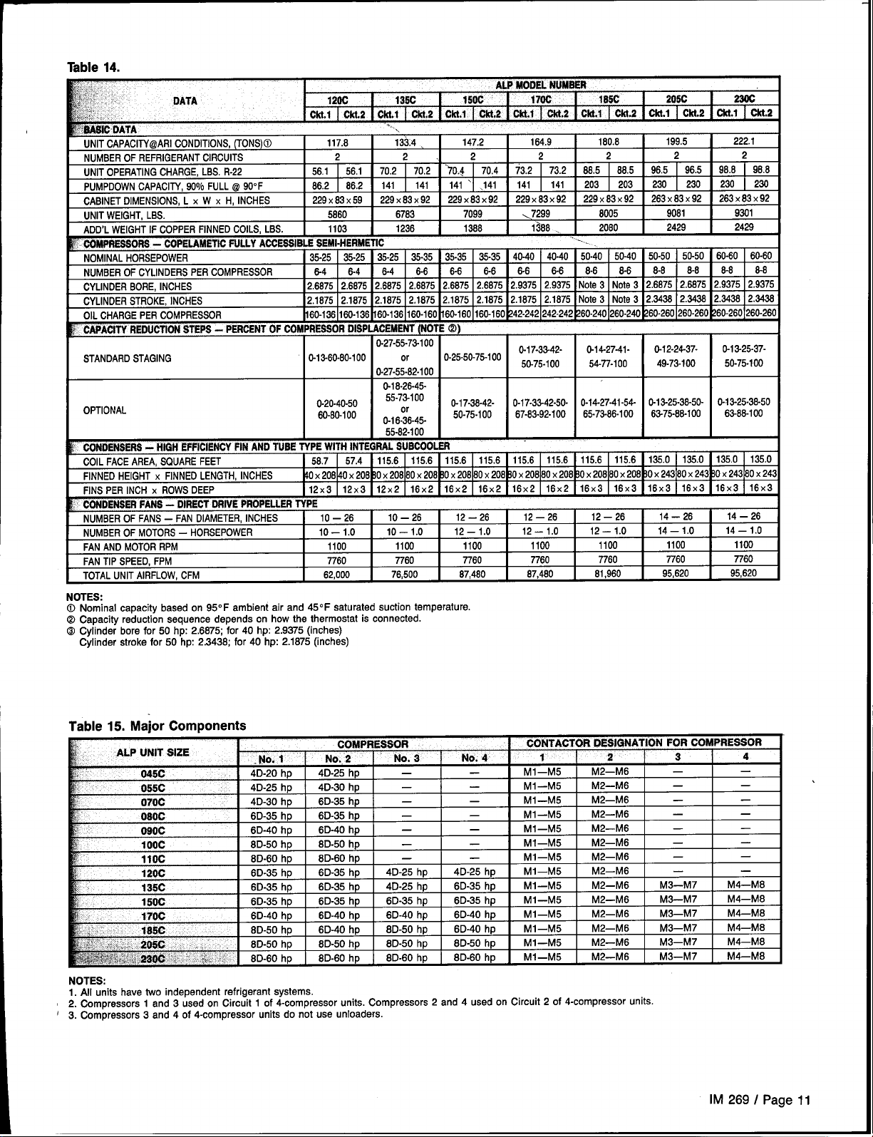
Table 14.
1200
Of&l I ckt.2 I CkLl I ckt.2
UNIT CAPACllY@ARlCONDITIONS,(TONS)@
NUMBEROF REFRIGERANTCIRCUITS
UNIT OPERATING[
PUMPDOWNCAPACITY, 900/0FULL @ 90”F
CABINET DIMENSIONS,L X W X H, INCHES
UNIT WEIGHT, LBS.
ADD’L WEIGHT IF COPPERFINNED COILS, LBS.
: COfdPfE880f?8 - COPELAMETICFULLY AGGRiWI%t
NOMINALHORSEPOWER
NUMBEROF CYLINDERS PER COMPRESSOR
CYLINDERBORE, INCHES
CYLINDERSTROKE, INCHES
OIL CHARGE PER COMPRESSOR
~ CAPACITY REDUCTIONSTEPS - PERCENTOF COMPRESSORDISPLACEMF”’
STANDARDSTAGING
I
) HEIGHT X FINNED LENGTH, INCHES ~0 X206~0 X206~0 X208180 X208~0 X208160X206~0 X208180X2C
CHARGE,LBS. R-22
. ... . .. . ... . .. --------- - --. ., ..--. .—. -
117.8 1334> 147.2
56.1 ] 56.1 70.2
86.2 86.2 141
229X83X 59 229X83X 92
5860 6783 7099
stmi.ntnsmIw
35-25
8-4
2.6875 2.6875
=1211375 ]2187512167521875121675121875 12~875lNote3INote312~ 12~
~60-1361160-136 ~6Ll136~
0-13-60-80-100 or
I
.,,\
2
1103 1236
35-25 35-25
6-4 6-4
2.6875
.“7.
U-L(-55-73-1OO
0-27-55-82-100
I1400CAC
ALP MODELNUMBEN
135C 150C
EI+T(NOTE Q
Cftt.1 I CW2 1 Cfrt.1 I CM.2
—
2. 2
70.2 )0.4 70,4 73.2 73.2
141 141 ‘1 .141 141
229X83X 92 229X83X 92 229X83X 92 263X83X 92 263X83X 92
1388
35-35 35-35
6-6
6-6
2.6675 2.6875
0-25-50-75-100
40-40 40-40
35-35
6-6 6-6 8-8 8-6 6-6 8-8
2.9375 2.9375
2.6675
170C
164.9
2 2
141
\7299
1388, 2060
0-17-33-42- 0-14-27-41-
50-75-100 54-77-100
105C
Cfd.1 ckt.2
~
180.8
88.5 98.5 96.5 98.8
68.5
203 203
6005
50-40 50-50
50-40
Note 3 2.6875 2.6675
Note 3
2060 220C’
Cld.1 ckr.2 Ckt.1 citt.2
~
199.5 222.1
230
9081 9301
2429 2429
0-12-24-37- 0-13-25-37-
49-73-100
~
2 2
I 98.8
230 I 230
230
50-50
60-60
8-6 8-8 M
2.9375
2.3436 2.3438
50-75-100
60-80
2.9375
TOTAL UNIT AIRFLOW, CFM
I
NOTES:
0 Nominal capacity based on 95°F ambient air and 45°F saturated auction temperature.
@ Capacity reduction sequence depends on how the thermostat is connected.
COCylinder bore for 50 hp: 2.6875; for 40 hp: 2.9375 (inches)
Cylinder stroke for 50 hp: 2.3438; for 40 hp: 2.1875 (inches)
62,000
I
76,500
I
87,480
I
67,480
I
81,960
I
Table 15. Major Components
COMPRESSOR CONTACTOR DESIGNATION FOR COMPRESSOR
4D-20 hp
4D-25 hp
4D-30 hp 6D-35 hp
Eli
..
090C
1Ooc
I1OC
Osoc
6D-35 hp
I
6D-40 hp
8D-50 hp
I
BD-60 hp
120C 6D-35 hp
135C
150C 6D-35 hp
w$:$~k.i,
...
NOTES:
1. All units have two independent refrigerant systems.
2. Compressors 1 and 3 used on Circuit 1 of 4-compressor units. Compressors 2 and 4 used on Circuit 2 of 4-compressor units.
3. Compressors 3 and 4 of 4-compressor units do not use unloaders.
G:. ,.
-$’”*W “t ..’5:.$% “ $
6D-35 hp
6D-40 hp
I
8D-50 hp
6D-50 hp
1
6D-60 hp
4D-25 hp
4D-30 hp
6L-W” ,IV
I
6D-40 hp ] —
8D-50 hp
6D-60 hp ] —
6D-35 hp
6D-35 hp
6D-35 hp 6D-35 hp ] 6D
8D-40 hp 6D-40 hp
6D-40 hp 8D-50 hp
6D-50 hp 8D-50 hp
8D-60 hp 8D-60 hp
—
—
—
1 1 1
— —
4D-25 hp
—
—
—
—
—
4D-25 hp
)-35 hp
6D-40 hp
6D-40 hp MI–M5 M2—M6
8D-50 hp
8D-60 hp
M1—M5 M2—M6 —
MI—M5
M1—M5 M2—M6 —
Mi—MK
,.! . . , ...- ..M1—M5 M2
MI—M5 M2—M6 —
I
MI–M5 M2—M6 —
MI—M5 M2—M6 I —
I
MI—M5 M2—M6 M3—M7
M1—M5 M2—M6
MI–M5 M2–M6
M1—M5 M2—M6
1
MI—M5 M2—M6
M2—M6 —
M7—M6
&flJ6 — —
95,820
I
M3—M7 M4—M6
M3—M7 M4—M8
M3–M7 M4—M6
M3–M7 M4—M6
M3–M7 M4—M8
I
— —
,
95,620
—
—
—
—
—
—
M4—M8
1
!
1
1
IM 269 / Page 11
Page 12
1
Figure 8. Dimensional Data — ALP-045C thru 120C
~ 2.5
,—
ABINET
DIA. LIFTING HOLES
AIR
DISCHARGE
\
t
\
,o~
Eli/
Lli J
2.0 TYP. -’~
SPACING FOR
1.00. DIA
ISOLATOR
MOUNTING
HOLES (6)
II
Mac
Ossc
070c
Oaoc
Osoc
100C 226.7
11OC 226.7 5.7
120C
122.7
175.7
175.7
228.7 7.2 7.2 22.6
228.7 7.2
226.7
39.2
9.0
9.5
8.7
5.7
9.0 21.6
8.7 22.6
7.2 22.6
7.2 24.6
5.7 27.2
5.7 27.2
39.2 23.6
22,3 38.3
22.6 43.6
22,6 43.6
22.6 46.5
24,6 46.5
27.2 46,5
27.2 46.5
23.8 97.5
11OC
120C
00
00
00
00
00
El
61,6 22,8
43,6 52,2
43.6 52,2
46.5 52,2
46.5 52,2
46,5 52.2
46,5 52.2
97,5 93.7
FAN ARRANGEMENTS
080C
090C
1Ooc
070C
00
00
00
El
1ye
15h 2%
21A 2%
21A 21/i
21A 21A
25A
2%
25h
1ye
278
278
2%
055C
00
00
1
045C
o
00
El
%
%
7%
%
% %
7%
11A
11A
CENTEROF lSOIATOR
7/8
%
%
7/8
‘h
1~~
11A
51.0
65.0
66.0
64.0
63.0
80.0
81.0
85.9
13.0 43.0
13.0 58.0
13.0 58.0
13.0 58.0
13.0 58.0
13.0 56.0
13.0 58.0
13.0 58.0
109.0
162.0
162.0
215.0
215.0
215.0
215.0
215.0
Page 12/ IM 269
Page 13
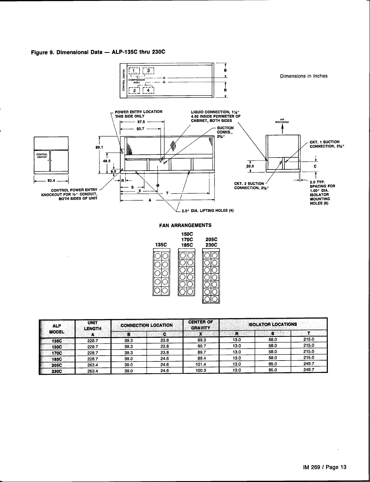
Figure 9. Dimensional
CONTROL
CENTER
..
lid
1-8-’4
cONTROL POWERENTRY
KNOCKOUTFOR !4If CONDUIT,
BOTHSIDES OF UNIT
— ALP-135C thru 230C
Data
1
r
8
+
v
2.5,1 DIA. LIFTING HOLES
FAN ARRANGEMENTS
150C
135C
———
170C
185C
00
00
00
00
00
B
205C
230C
00
::
00
00
00
00
%
II 4
CKT. 2 SUCTION
CONNECTION,2%11
(4)
Dimensions in Inches
AK!
DISCHARGE
t
/
+~ 2.O’TYP.
SPACINGFOR
1.00~ DIA.
iSOiATOR
MOUNTING
HOLES(6)
LENGTH ‘ “.
:
23SC
B
263.4
263.4
B ‘. ~ 6 ‘ ;.3 :’ “
39.0
39.0
24.6
24.6
101.4
100.3
ISOLA’TO,RLOCATIONS
ii ‘ ‘
13.0
13.0
“,.:”’.s-’’ ,”:
95.0
95.0
.T
249.7
249.7
IM 269 / Page 13
Page 14
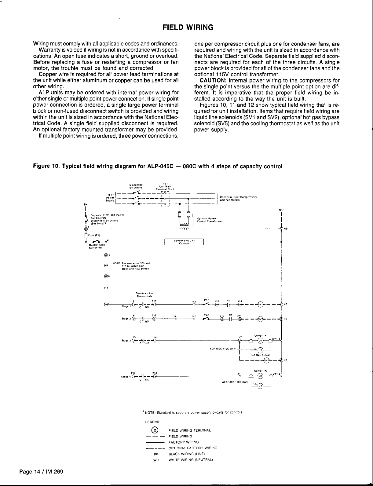
FIELD WIRING
Wring must comply with all applicable codes and ordinances.
Warranty is voided if wiring is not in accordance with specifications. An open fuse indicates a short, ground or overload.
Before replacing a fuse or restarting a compressor or fan
motor, the trouble must be found and corrected.
Copper wire is required for all power lead terminations at
the unit while either aluminum or copper can be used for all
other wiring.
ALP units may be ordered with internal power wiring for
either single or multiple point power connection. If single point
power connection is ordered, a single
block or non-fused disconnect switch is provided and wiring
within the unit is sized
in accordance with the National Elec-
large power terminal
trical Code. A single field supplied disconnect is required,
An optional factory mounted transformer may be provided,
If multiple point wiring is ordered, three power connections,
Figure 10. Typical field wiring diagram for ALP-045C
L),,mnn,d
,Ph,––-r,l--r,l
BK
~“w::z:::---~;j;j
By O!her.
Termna-
PB 1
U“,!Ma!”
Bl,ck
one per compressor circuit plus one for condenser fans, are
required and wiring with the unit is sized in accordance with
the National Electrical Code. Separate field supplied discon-
nects are required for each of the three circuits. A single
power block is provided for all of the condenser fans and the
optional 115V control transformer.
CAUTION: Internal power wiring to the compressors for
the single point versus the the multiple point option are different. It is imperative that the proper field wiring be installed according to the way the unit is built.
Figures 10, 11 and 12 show typical field wiring that is required for unit installation, Items that require field wiring are
liquid line solenoids (SVI and SV2), optional hot gas bypass
solenoid (SV5) and the cooling thermostat as well as the unit
power supply.
— 080C with 4 steps of capacity control
Condense,U.(I Comrx-m”
1
●nd Fan
T
T
M.!ors
F.,,(F,]
L..i—,
cont..! stop
SW!ch,,,,
,
6
t
510
L
T,rm<na!, For
T1’,mmsta!s
8 yl+
2!3
slag, 4 G+ >N;
Co”d,n,>ngU“ 1
control,
236
.
I
PSI ,,,
,,2
~—@+w&”-–@Y ---
‘Lp’Occ’’OcO”” la”””’
camp, .1
217
0
c
Page 14 / IM 269
●NOTE: Standard M separate Pcwr supply c,rcaI1s for ccc:rols
LEGEND:
@ FIELD WIRING TERFIINAL
———
— FACTORY WIPING
‘-— OPTIONAL FACTORv WIRING
FIELD WIRING
BK BLACK WIRING (LINE)
WHITE WIRING (NEUTRAL)
WH
Page 15
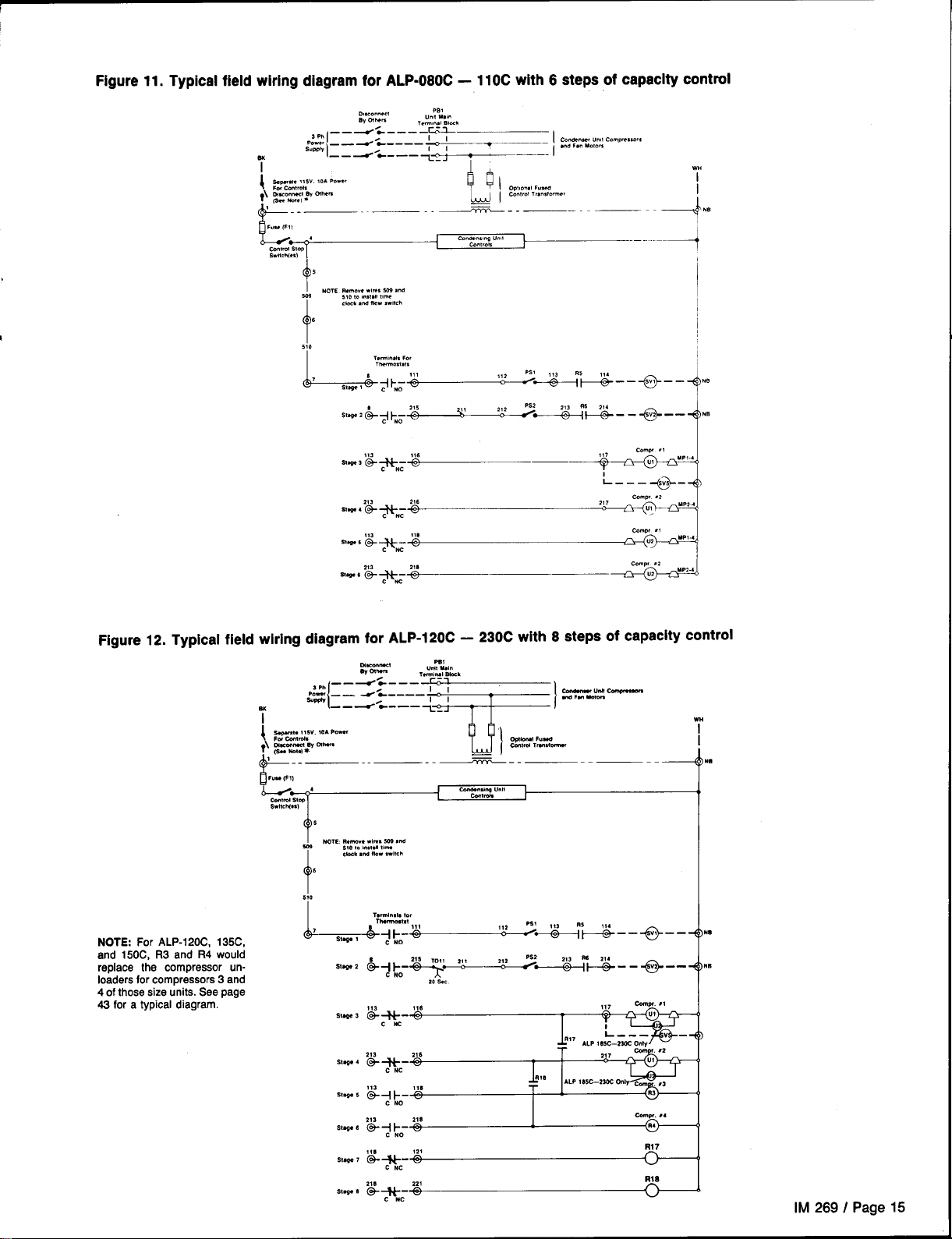
Figure11.Typicalfield wiring diagram for ALP-080C –
10C with 6 steps of
capacitycontrol
D!mmcec!
B, Olht.
—
.--” . . ...%
ml
Si’+-:-::--?: ! :
CO.,*
stop
S.”ch,e%)
~
Nom mm.”.w!m. m .?4
5?0 m 0“.,.11 t,-.
dock .“d !!0. ,.,,,.
6
t
570
L-#J;.i ~ 2aii.-e-.jNn
m 1
U“ll u.,.
TWm..( B-k
—--—
..-’3,”.!!
_ ,
~
T
h
OPI’.”.,~“-
Ca.tr.i Tr..,tc.me!
1
C.tatncec “.<1 C.m,re’t.m
I
. . . F.. ..,.-
I
---—--i”
----4
Figure 12. Typical field wiring diagram for ALP-120C –
ym;:w. ,OA m-
i
—*W m
NOTE: For ALP-120C, 135C,
and 150C, R3 and R4 would
replace the compressor un-
loaders for compressors 3 and
4 of those size units. See page
43 for a typical diagram.
?’(9a No,.)
,.” p,,
L.i —, —,
4
‘aMld Stw
S“llchl”)
s
?
~ NOTE R.Mv. .1”. - .“d
—.-—--
s, 0,.,.,,.11 ,he
dock sw lb. ,wl,ch
Stm
2
Stw.e 3
w+- ‘z
CW2
213
Stls+ 4
(+ ~c- ‘~
,13
S,qw 5
@:I-o- Y
230C with 8 steps of capacity control
~+TF&y_
w
ml
C4nds.sing U“(I
Cantmh
R78
R17
ALP , 8SC–2W Only
117
Y
I
L
..—
c-w .,
,8
IB
Sting. 6
SW.9 7
SW+ a
IM 269 / Page 15
Page 16
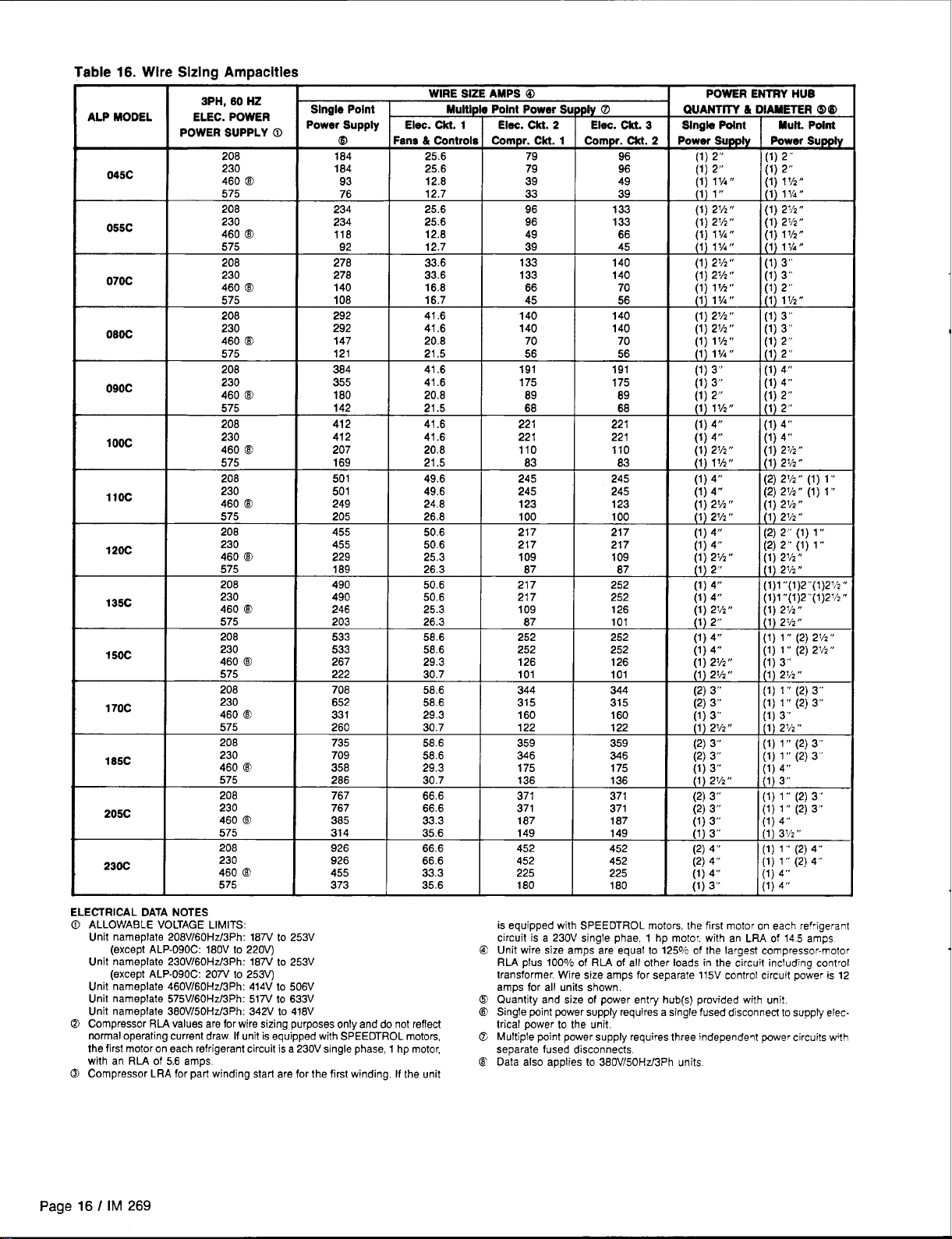
Table 16. Wire Sizing Ampacities
3PH, 60 HZ
ALP MODEL
045C
055C
070C
090C
1Ooc
Iloc
120C
135C
150C
170C
185C
205C
230C
ELEC. POWER
POWER SUPPLY O
208
230 184
460 @
208 1 278
208
230
5ktt
T
208 412
230 412
460 @ 207
460 (B
575 203
208
230
460 ~
575 222
206 708
230
4600
575 266
208 767
230 767
460 @
575
206
230
460 @
575
Single Point
Power Supply
r
m
184
I
I 93
292
292
I
246
533
533
267
652
331
385
314
926
926
455
373
I
WIRE SIZE AMPS @
Muitlple Point Power Supply O
Elec. Ckt. 1 Elec. Ckt. 2 Elec. CM. 3
Fene & tintrols Cornpr.Cti. 1 hmpf. m. 2
25.6 79
25.6
12.8
12.7
25.6 96 133
25.6
12.6 49 66
12.7 39
33.6 I 133 140
33.6
16,8
16,7 45
41.6
41.6 140
20.8 70
21,5
41.6
41.6 175 175 (1) 3“
20.6
21.5
41.6
41.6 221
20.8 110 110 (1) 2V2°
50.6 217
25.3
26.3
50.6 217
50.6
25.3
26.3
58.6 252 252 (1) 4“
58.6 252
29.3 126 126 (1) 21/2“
30.7 101 101
58.6
58.6 315 315 (2) 3“
29.3 160 160 (1) 3“
30.7
56.6 359 359 (2) 3“
58.6 346
29.3 175 175 (1) 3“
66.6 452 452 (2j 4“
33.3 225 225 (1) 4“
35.6 180
79
39 49 (1) 11/’4”
I
33 39
96
133
66 70
140
I
56 56
191
I
69 69
66
221 221
109 109 (1) 2v2 “
87 87
217
109
I
87
344
I
122 122
96
96
I
133 (1) 23/2”
45
140
56
140
140
I
70
191
I
68
221
217
252
252
126 (1) ZV2°
I
101
252
344
I
346
180 (1) 3“
POWER ENTRY HUB
I
QUANTIYY & i
I
Slngb Point
Power Supply
I
(1) 2“
ilj 2
I
‘l’ ,,,
(1) 23/2”
(1) 11A”
(Ij IIA,I
I
[1)2M”
{lj 2Th”
(1) lvz”
(1) l!~,,
(1)2V2“
(1) 2V2“
I
~1j 1VZ”
(1) 11/4,,
(1) 3“
I
~lj 2
1) 11/2”
1(
(1) 4“
(1) 4“
I
~lj 4!s
(1) 2“
(1) 49’
ilj 4’
I
‘1’ 2<,
(1) 4“
(1) 21/2,,
(2) 3“
I
21/2,,
~1j
(2) 3“
mm. Point
Power supply
(1) 2“
(1) 2“
(1)
l%”
~lj lIA.
(1) 272”
(1) 27/2“
(1)lYz”
11) 11~”
(1) 3“
(1) 3“
(1) 2’”
Jl) 1
1/2,,
(1) 3“
(1) 3“
(;) :“
(1) 4“
(1) 4“
(1) 2“
, 2.,
(1) 4“
(1) 4“
(1) 21/2“
(lj 2v2 r’
(2) 21A” (1) 1“
(2) 2Y2“ (1) 1 “
(1) 2V2“
jl j 21/2,,
(2) 2“ (1) 1’”
(2) 2“ (1) 1“
(1) 21/2“
(1) 21/2“
(1)1’’(1)2’’(1)2 ?>”
(1)1’’(1)2’’(1)2Y”
(1) 2Vz”
~lj z~hn
(1)1“(2) 2V2“
(1) 1“ (2)
(1)
(1) 21,2,,
(1) 1“ (2) 3“
(1) 1“ (2)3”
[1) 3“
[1) 21/2”
[1) 1“ (2) 3“
(1) 1“ (2) 3“
ilj 3
[1) 1“ (2) 3“
[1) 1“ (2) 3“’
[1) 4’”
[1) 3~/’2“
:1) 1“ (2) 4“
:1) 1“ (2) 4“
‘1) 4“
;1) 4“
2Y, “
3“
I
ELECTRICAL DATA NOTES
0 ALLOWABLE VOLTAGE LIMITS:
Unit nameplate 208V/60Hz/3Ph: 187V to 253V
(except ALP-090C: 180V to 220V)
Unit nameplate 230V/60Hz/3Ph: 187V to 253V
(except ALP-090C: 207U to 253V)
Unit nameplate 460V/60Hz/3Ph: 414V to 506V
Unit nameplate 575V/60Hz/3Ph: 517V to 633V
Unit nemerYate 360V/50Hz/3Ph: 342V to 418V
@ Compressor RLA values are for wire sizing purposes only and do not reflect
normal operating current draw If unit is equipped with SPEEDTROL motors,
the first motor on each refrigerant circuit is a 230V single phase, 1 hp
RLA of 5.6 amps
with an
@ Compressor LRA for part winding start are for the first winding. If the unit
Page 16 / IM 269
motor,
is equipped with SPEEDTROL motors, the first motor on each refrigerant
circuit is a 230V single phae, 1 hp motor, with an LRA of 145 amps
Unit wire size amps are equal to 125% of the largest compressor-motor
(!3
RLA plus 100o1oof RL4 of
transformer Wre size amps for separate 115V control circuit po;er is 12
amps for all units shown.
o
Quantity and size of power entry hub(s) provided with unit
E’
Single fxJint ~wer supply requires a single fused disconnect to supply electrical power to the unit.
Multiple point power supply requires three independent power circuits with
CL
separate fused disconnects
Data also applies to 380V/50Hz/3Ph units
@
all other loads in the circuit includnq control
Page 17
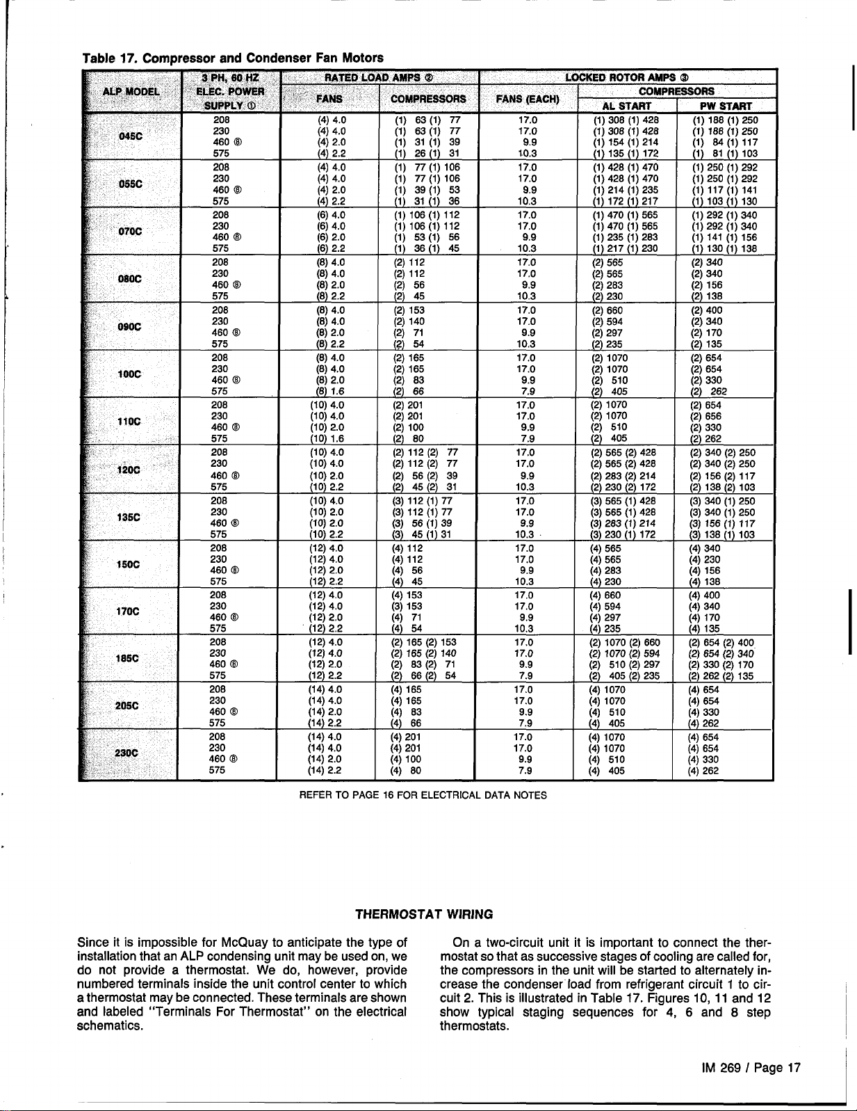
Table 17. Compressor and Condenser Fan Motors
XEO ROTOR AMPS @
COMPRESSORS
056C
“ 070C
080c
beoc
100C
11OC
.1200 ““”
f35c
160C
170C
185C
206C
Z30C
,.,’
(1) 31 (1) 39
208 (4) 4.0
230 (4) 4.0
4600
575
208 (6) 4.0
230 (6) 4.0
46063 (6) 2.0
575 (6) 2.2
208 (8) 4.0
230 (8) 4.0
460 @ (6) 2.0
575 (6) 2.2
206
230 (6) 4.0
460 @ (6) 2.0
575 (8) 2.2
208 (8) 4.0
230
460 @ (8) 2.0
575
I
208 (lo) 4.0
230
. .
460 @ (lo) 2.0
575
208
230 (lo) 4.0
460 @ (lo) 2.0
575
208 (lo) 4.0
230
460 @
575
208
230 (12) 4.0
460 @ (12) 2.0
575
208 (12) 4.0
230 (12) 4.0
460 @ (12) 2.0
575
206
230 (12) 4.0
460 @ (12) 2.0
575
208 (14) 4.0
230
460 @ (14) 2.0
575
208 (14) 4.0
230 (14) 4.0
460 @ (14) 2.0
575 (14) 2.2
(4) 2.0
(4) 2.2
(8) 4.0
(8) 4.0
(8) 1.6
I
(lo) 4.0
(10) 1.6
(lo) 4.0
(1o) 2.2
(lo) 2.0
(lo) 2.0
(lo) 2.2
(12) 4.0
(12) 2.2
(12) 2.2
(12) 4.0
(12) 2.2
(14) 4.0
(14) 2.2
REFER TO PAGE 16 FOR ELECTRICAL DATA NOTES
(1) 26 (1) 31
(1) 77 (1) 106
(1)77 (1) 106
(1) 39 (1) 53
(1) 31 (1) 36 10.3
(1) 106 (1) 112
(1) 106(1) 112
(1) 53 (1) 56 9.9
(1) 36 (1) 45 10.3
(2) 112
(2j 112
(2) 56
%--t-ik
i2i 71
m
{2j 66
(2) 201
(2) 201 17.0
%--HE
(2j 56 (2j 39
(2) 45 (2) 31 10.3
w--l--+
i4i 56
(4j 45
(4)
153
h--l-+
m
I
I
I
I
I
I
10.3
17.0
17.0
17.0
17.0
17.0
17.0
17.0
9.9
9.9
10.3
17.0
9.9
9.9
9.9
9.9
7.9
-
(2j 565
(2) 283 (2) 156
{2j 405
(2) 1070
(2) 1070 (2) 656
(2j 565 (2j 428 @j 340 @j 250
(2) 283 (2) 214
(2) 230 (2) 172
(3) 565 (1) 426
(3) 565 (1) 428 (3) 340 (1) 250
(3) 283 (1) 214 (3) 156 (1) 117
(3) 230 (1) 172 (3) 138 (1) 103
(4) 565
(4) 565 (4) 230
i4i 283
i4j 230 i4j 138
(4) 660 (4) 400
(zj340
I
(2j 262
(2) 654
(2) 156(2) 117
(2) 138 (2) 103
(3) 340 (1) 250
(4) 340
I i4i 156
km--l-L
i4j 510 I i~ 330
m
THERMOSTAT WIRING
Since it is impossible for McQuay to anticipate the type of
installation that an ALP condensing unit maybe used on, we mostat so that as successive stages of cooling are called for,
do not provide a thermostat. We do, however, provide the compressors in the unit will be started to alternately innumbered terminals inside the unit control center to which
a thermostat maybe connected. These terminals are shown
and labeled “Terminals For Thermostat” on the electrical show typical staging sequences for 4, 6 and 8 step
schematics. thermostats.
On a two-circuit unit it is important to connect the ther-
crease the condenser load from refrigerant circuit 1 to circuit 2. This is illustrated in Table 17. Figures 10, 11 and 12
IM 269 / Page 17
Page 18
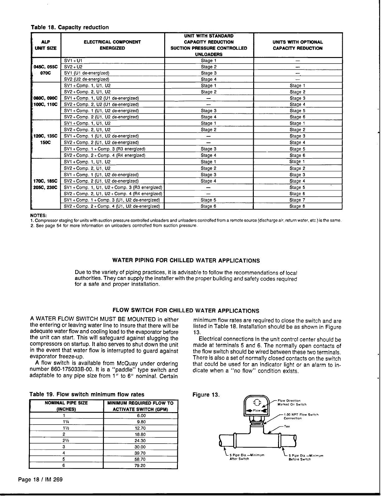
Table 18. Capacity reduction
UNIT WrTH STANDARD
ELECTRICAL COMPONENT
ENERGIZED SUCTION PRESSURE CONTROLLED
I
UNIT
ALP
SIZE
Svl +Ul
45C, 055C
070C
Sot, Oeoc SVl+Comp. l, U2(Ul da-energized)
Ooc,
20C, 135C SVI + Comp. 1 (UI, U2 de-energized)
150C SV2 + Comp. 2 (U1, U2 de-energized)
70C,
05C, 230C
NOTES:
1. Compressor staging for units with suction pressure controlled unloaders and unloaders controlled from a remote source (discharge air, return water, efc ) is the same
2. See page 54 for more information on unloaders controlled from suction pressure.
SV2 + U2
SV1 (Ul de-energized)
SV2 (U2 de-energized)
SV1 +Comp. 1, Ul, U2
SV2 +Comp. 2, Ul, U2
11OC SV2+Comp.2, U2(Ul da-energized)
SVl+Comp, 1 (Ul, U2 de-energized)
SV2 + Comp, 2 (Ul, U2 de-energized)
SVI +Comp, 1, Ul, U2
SV2 +Comp. 2, Ul, U2
SVI + Comp. 1 + Comp. 3 (R3 energized)
SV2 + Comp. 2 + Comp. 4 (R4 energized)
SV1 +Comp. 1, I-H, U2
SV2+Comn. 2. U1. U2
SV1 + Comp, 1 (U1, U2 de-energized)
SV2 + Comp. 2 (Ul, U2 de-energized)
1S5C
SV1 + Comp. 1, U1, U2 + Comp. 3 (R3 energized)
SV2 + Comp. 2, UI, U2 + Comp. 4 (R4 energized)
SV1 + Comp. 1 + Comp. 3 (Ul, U2 de-energized)
SV2 + Comp. 2 + Comp. 4 (Ul, U2 de-energized)
I
1
CAPACITY REDUCTION
I
UNLOADERS
Stage 1
Stage 2
Stage 3
Stage 4
Stage 1
Stage 2
—
—
Stage 3 Stage 5
Stage 4 Stage 6
Staga 1 Stage 1
Stage 2
—
—
Stage 3
Stage 4 Stage 6
Stage 1
Staoe 2
Stage 3 Stage 3
Stage 4
—
—
Stage 5
Stage 6
1
I
UNtTS WITH OPTiONAL
CAPACITV REDUCTION
—
—
—
—
Stage 1
Stage 2
Stage 3
Stage 4
Stage 2
Stage 3
Stage 4
Stage 5
Stage 1
Staae 2
Stage 4
Stage 5
Stage 6
Stage 7
Stage 6
WATER PIPiNG FOR CHILLED WATER APPLICATIONS
Due to the variety of piping practices, it is advisable to follow the recommendations of local
authorities. They can supply the installer with the proper building and safety codes required
for a safe and proper installation.
FLOW SWITCH FOR CHILLED WATER APPLICATIONS
A WATER FLOW SWITCH MUST BE MOUNTED in either
the entering or leaving water line to insure that there will be
adequate water flow and cooling load to the evaporator before
the unit can start. This will safeguard against slugging the
compressors on startup. it also serves to shut down the unit
in the event that water flow is interrupted to guard against
evaporator freeze-up.
A flow switch is available from McQuay under ordering
number 860-175033B-O0. it is a “paddle” type switch and
adaptable to any pipe size from 1” to 6“ nominal. Certain
Table 19. Flow switch minimum flow rates
NOMINAL PIPE SIZE
I
i
I
(INCHES) ACTIVATE SWITCH (GPh3)
1
11A
11/2
2
21/2
3 30.00
4 39.70
5 58.70
6 79.20
MINIMUM REQUIRED FLOW TO
I
6.00
9.80
12,70
I
18.80
24.30
minimum flow rates are required to close the switch and are
listed in Table 18. installation should be as shown in Figure
13.
Electrical connections in the unit control center should be
made at terminals 5 and 6. The normally open contacts of
the flow switch should be wired between these two terminals.
There is also a set of normally closed contacts on the switch
that could be used
dicate when a “no
Figure 13.
I
for an indicator light or an alarm to inflow” condition exists.
Flow Oireclion
1.00 NPT FIOW Switch
L,,,,, 0,. -M”,rn”nl
Switch
Aiter
~ 5 Pipe Oia -Minimum
eefore %ftch
Page 18 I iM 269
Page 19

EVAPORATOR FAN INTERLOCK FOR AIR HANDLER COIL INSTALLATIONS
It is important to interlock the air handler evaporator fan with
the condensing unit control to insure that there will be a cool-
ing load on the evaporator before the unit can start to pre-
vent compressor slugging. A pair of terminals for each
refrigerant circuit is available in the unit control center for this
UNIT LAYOUT & PRINCIPLES OF OPERATION
purpose. Remove the jumpers between terminals 111 and
112 for circuit 1 and211 and 212 for circuit 2. Use these ter-
minals for the evaporator fan interlock contacts. Be sure to
keep circuits separate by using two contacts on dual circuit
machines.
-J
Figure14.
Major Component Locations
The figures below illustrate component locations within the unit for each unit size.
COMPRESSOR No. 1
M
~ E? I@@@@
COMPRESSOR No. 2
L- -1
TOP VIEW OF UNIT
205C, 230C
*
COMPRESSOR No. 1
COMPRESSOR
No. 2
CONTROL CENTER
All electrical controls are enclosed in a weatherproof control
center with keylocked, hinged access doors. The control
center is composed of two separate compartments, line
voltage and control voltage, All of the line voltage components, except for the input terminals of the PVM, are
‘\
— COMPRESSOR No. 4
located in the compartment on the right side of the unit. The
control voltage components are located on the left side with
the live terminals located behind a deadfront panel. This protects service personnel from live terminals when accessing
the adjustable and resettable controls.
IM 269 / Page 19
Page 20

CONTROL CENTER LAYOUTS – ALP-045C thru 11OC
————_
Figure 15. Left Side, 115V Control Section
Figure 16. Right Side, High Voltage Power Section
7 FHmmI
ODDOU
P
m
PB2
El
o
PB3
n
————
CBS
CB1
.—— ——— —
m
II EII
CONTROL CENTER LAYOUTS — ALP-120C thru 230C
Figure 17. Left Side, 115V Control Section
TB5 (40–63)
Raceway
=
El
[ TB4(II0-124)(210-224) I I I ~[~
I
I II
TB6 (70–93)
Raceway
GRD 9
IT
T2
n
NOTE: PB1, PB2, PB3 are used with multiple point power wiring.
Figure 18. Right Side, High Voltage Power Section
I
PVM
o
PB2
El
n
PB3
El
~mmjm
——————
.——————
—. —
————
——
EIEI
Page 20 / IM 269
EIEI
TC
1
11
mIimEIE
NOTE: PB1, PB2, PB3 are used with multiple point power wiring.
Page 21

ELECTRICAL LEGEND
DESIGNATION
AB
Cll, C21
CBI-S
COMPFI.1-4
CP1
CP2
DAC1
DAS1
DW
FI
F2
FB1–4
FS5
FB6–10
FBI ,2
GFI
GRD
HPI, 2
—4
HTRI
HTR5
JB5
JS6
LP1 , 2
Ml–lo
MI1-27
MJ
MPI-4
MTR1 1-27
NB
NSS
OP1–4
PBI–3
PC1–4
PC5, 6
PC8–10
PC12-22
Psi, 2
PVM
DESCRIPTION STD. LOCATION
ALARM SELL
CAPACITORS FOR SPEEDTROL MOTORS
CIRCUIT BREAKERS, COMPRESSOR
MOTORS
COMPRESSORS 1 THRU 4
CENTRAL PROCESSOR
CENTRAL PROCESSOR SATELLITE
DISCHARGE AIR CONTROL
DISCHARGE AIR SATELLITE
DISCONNECT SWITCH, MAIN
FUSE, CONTROL CIRCUIT
FUSE COOLER HEATER
FUSEBLOCKS, COMPRESSOR MOTORS
FUSE SLOCK, CONTROL POWER
FUSESLOCKS, FAN MOTORS
FREEZESTATS, CONTROL
GROUND FAULT INTERRUPTOR
GROUND
HIGH PRESSURE CONTROLS
HEATERS, COMPRESSOR CRANKCASE
HEATER, COOLER BARREL
JUNCTION SOX FOR COOLER HEATER
JUNCTION SOX FOR HEAT RECOVERY
LOW PRESSURE CONTROLS
CONTRACTORS, COMRPESSOR
CONTRACTORS, FAN MOTORS
MECHANICAL JUMPERS
MOTOR PROTECTORS, COMPRESSOR
MOTORS, CONDENSER FANS
NEUTRAL SLOCK
NIGHT SETBACK
OIL PRESSURE CONTROLS
POWER SLOCK, MAIN
PRESSURE CONTROLS, SPECIALS
PRESSURE CONTROLS, HI AMSIENT
UNLOAOER
PRESSURE CONTROLS, SUCTION UNLOAOER
PRESSURE CONTROLS, FANTROL
PUMPDOWN SWITCHES
PHASE VOLTAGE MONITOR
FIELD MOUNTEO
BACK OF CONTROL SOX OR
ON BULKHEAD
CONTROL SOX
BASE OF UNIT
CONTROL SOX
CONTROL SOX
CONTROL SOX
CONTROL SOX
CONTROL SOX
CONTROL SOX
CONTROL BOX
CONTROL SOX
CONTROL BOX
CONTROL BOX
SUCTION LINE NEAR COOLER
CONTROLSOX
CONTROLSOX
ON COMPRESSOR
ON COMPRESSOR
WRAPPEO AROUNO COOLER
SARREL
NEAR COOLER ON SASE RAIL
UNOERSIOE OF COIL ON lNTERMEOIATE TUSE SHEET
ON COMPRESSOR
CONTROL BOX
CONTROL SOX
CONTROL BOX
COMPRESSOR JUNCTION BOX
CONOENSER SECTION
CONTROL BOX
CONTROL SOX
CONTROL SOX
CONTROL SOX
CONTROL SOX OR ON UNIT
ON COIL HEADER
CONTROL SOX
ON COIL HEADER
CONTROL SOX
CONTROL SOX
DESIGNATION
Rl, 2
R5–8
R9–12
R13, 14
R3, 4, 17, IS
R19
R21 ,22
R23-30
RS14
51
S2-4
S5
SC1l, 12
SL1
Svl , 2
SV5, 6
SV1O, 20
Svll, 21
T1
T2
T3
TS2
TS3
TB4-6
TCI
TC2
TCIO
TC11
TC12
TC12-25
TOI-4
T05–S
T09, 10
TO1l, 12, 13
TO14
T015, IS
T017; 18, 19
T020–24
U1, 2
OESCFNPTION
RELAYS, RESET OR ALARM
RELAYS, SAFETY
RELAYS, STARTING
RELAYS, LOW AMBIENT START
RELAYS, CAPACITY CONTROL
RELAY, HEAT RECOVERY
RELAYS, HI AMBIENT, HI RETURN
SUCTION UNLOAOERS
RELAYS, SPECIALS
RESET SWITCHES
SWITCH, CONTROL STOP
SWITCHES, LEAO-LAG
SWITCH, HEAT RECOVERY
SPEEO CONTROLS
SOLENOIO 000R LOCK
SOLENOIO VALVES, LIc2UI0 LINES
SOLENOIO VALVES, HOT GAB BYPASS
SOLENOIO VALVES, WATER CONOENSER
(NORMALLY OPEN)
SOLENOIO VALVES, AIR CONOENSER
TRANSFORMER, MAIN CONTROL
TRANSFORMER, 24V CONTROL
TRANSFORMER, FAN SPEEOTROL
TERMINAL BLOCK, 120V, FIELO
TERMINAL BLOCK, 24V. FIELO
TERMINAL BLOCKS, CONTROL
THERMOSTAT, UNIT
THERMOSTAT, COOLER SARREL
THERMOSTAT, SPECIAL
THERMOSTAT, HIRETURN WATER UNLOAOER CONTROLSOX
THERMOSTAT, SPECIAL
THERMOSTATS, FANTROL
TIME OELAYS, COMPRESSOR LOCKOUT
TIME OELAYS, COMPRESSOR PART WINOING CONTROL BOX
TIME OELAYS, LOW AMSIENT
TIME OELAYS, COMPRESSOR SEQUENCING
TIME OELAY, ALARM BELL
TIME OELAYS, FREEZESTAT
TIME OELAYS, HEAT RECOVERY
TIME OELAYS, SPECIAL
UNLOADERS
WATER &
S70. LOCATION
CONTROL BOX
CONTROL BOX
CONTROL BOX
CONTROL SOX
CONTROL SOX
CONTROL BOX
CONTROL SOX
CONTROL BOX
CONTROL BOX
CONTROL SOX
CONTROL SOX
CONTROL BOX
SACK OF CONTROL SOX OR
ON BULKHEAD
CONTROL SOX
CONOENSER SECTION
CONOENSER SECTION
CONOENSER SECTION
CONDENSER SECTION
CONTROL SOX
CONTROL SOX
ON BULKHEAD
CONTROL BOX
CONTROL BOX
CONTROL BOX
CONTROL SOX
ON COOLER
cONTROL sox OR ON UNIT
CONTROL SOX OR ON UNIT
CONTROL BOX
CONTROL BOX
CONTROL BOX
CONTROL SOX
CONTROL SOX
CONTROL SOX
CONTROL SOX
CONTROL SOX
ON COMPRESSORS
Figure 19. Recommended Unit Disconnect Location
HINGEO 000RS
ON CONTROL
CENTER
\
NOTE:
MOUNT DISCONNECT ON STATIONARY
PANEL SO THAT IT 00ES NOT INTER.
FERE WITH HINGED 000RS OR WITH
AIR INTAKE INTO COIL.
\
S.00 MIN.
4’
IM 269 I Page 21
Page 22

NORMAL SEQUENCE OF OPERATION
The following sequence of operation is typical for ALP
SEASONCON air cooled condensing unit, models ALP-045C
through ALP-230C (items in italics apply only to Mode/s
ALP-720C thru ALP-230C). The sequence varies somewhat
depending upon options.
Startup
stop switch S1 closed, 115V power is applied through the control circuit fuse F1to the compressor crankcase heaters HTR1,
HTR2 (HTR3, HTR4), the compressor motor protectors MP1,
MP2 (MP3, MP4) and the primary of the 24V control circuit
transformer. The 24V transformer provides power to the contacts of the low pressure controls LPI and LP2 and the com-
pressor lockout time delays TDI and TD2.
When the remote time clock or manual shutdown switch
turns on the chilled water pump, the flow switch closes and
115V power is applied to the relay contacts on the unit ther-
mostat. The unit will automatically operate in response to the
unit thermostat provided the manual pumpdown switches PS1
and PS2 are closed (in the ‘(auto” position); the compressor
lockout time delays TD1 and TD2 have closed, energizing the
safety relays R5, R6 (Rz R8); and the freezestats FS1 and
FS2, high pressure controls HP1 and HP2, and compressor
motor protectors MP1, MP2 (MP3, MP4) do not sense failure
conditions.
On a call for cooling, the unit thermostat energizes the liquid line solenoid valve SV1 for refrigerant circuit #1. This
opens the valve and allows refrigerant to flow through the expansion valve and into the evaporator. As the evaporator
refrigerant pressure increases, the low pressure control LPI
closes. This energizes the compressor starting relay R9, starting the compressor via the compressor contractors Ml and
With the control circuit power on and the control
—
M5. Closing the R9 contacts also energizes the condenser
fan motor contacts Mll, M12, M13 and M14, starting the fan
motors.
As additional stages of cooling capacity are required, the
unit thermostat energizes the liquid line solenoid valve SV2
of the refrigerant circuit #2. After the compressor sequenc-
ing time de/ay TD77 has closed, the same starting sequence
is initiated in refrigerant circuit #2.
If still more cooling is required, the unit thermostat will start
the remaining compressors and then de-energize unloader
solenoids until the capacity requirement is met.
Pumpdown
energize unloaders and unload the compressors, and then
de-energize the liquid line solenoid valves SV1 and SV2, causing the valves to close, When the compressor has pumped
most of the refrigerant out of the evaporator and into the condenser, the low pressure controls LPI and LP2 WiIIopen, shutting down the compressors and the condenser fan motors,
If refrigerant leaks into the evaporator, the increse in pressure
will cause the low pressure control LPI or LP2 to close, This
will energize the compressor starting relays R9 or R1O and
start the compressor, which will quickly pump the refrigerant
out of the evaporator and into the condenser (recycling
pumpdown).
A compressor which repeats recycling pumpdown every 5
minutes indicates a malfunction due to the temperature con-
trol or a system cause. A build up of heat in the compressor
without proper cooling of suction gas could cause a
mechanical failure in the compressor. McQuay recommends
corrective measures be taken if the compressor recycles
repeatedly within 15-minute intervals. “
— As the unit thermostat is satisfied, it will
CANADIAN
Canadian units which are CSA listed and are equipped for
multiple point power connections have a sticker (see figure
at right) next to the wiring diagram in the control box, This
notifies the installer that local authorities may require the unit
to be connected to a single electrical power source. Check
with local authorities for requirements.
CSA LISTING
Although this unit may
be provided with
options requiring more
than one source of
electrical supply, some
electrical inspection
authorities may require
this unit to be
connected to a single
external electrical
supply.
Page 22 / IM 269
Page 23

TYPICAL POWER WIRING DIAGRAMS
SINGLE POINT, WITHOUT SPEEDTROL
I
ALP-045C
ALP-045CI055C —
— 2081230V, AL, PW
380/41 514601575V, AL, PW
Ill
P%l
F“=E
L_L_T*’”
,,..,
+&t-t-.+’ ,
.!, 0“ ““ITS WITH
s.0/.13/4.0 /57,“-AL.
F
!.”.
...
I
L
I*
J
=%l=’=z
FB6
Ml!
.--,,,—
—,!, —
—,, ,—
FB7
..
I
M!2
m=’== =
ila---”
—,, s—
1“
I
<
f’”’%+y:[
7+”k @~; - –
1,
COMPR
*2
*@
=0 V./50-60 HZ
FROM 0S1 Q& PBI
I
u
+1++ “ b.’+ ’:2
, ‘-tam “ *.A%
,
o+”’L,
“--l=+ ~~
“*M
\
L1— L2
T( 12
—
I F05
—
ALP-055C, 2081230V
T
./,
,eo/41s/4eon73 v-AL.
INCLUDESCB6 FORCOMPRESSOR
0“ ““11s WITH
200 V /60 HZ
FROM 0S1 sx PO!
U- L2
I
,1 TZ
—
m
FROM DSI E PB1
U- LZ
,2 I
I
,,
—
m
4AG.1+
““’+mky:,
!15 v.
I ,05
I
—,,.—
—l, s—
#2
FROM 0S1 E PBI
u- L2
I
,1 12
m
“,H3H2H4
kid
FROM 0S1 X PBI
F,5
G
U- L2
I
,, T2
m
—
,,
—
I F,,
I ,,5
575 V/60 HZ
FROM 0S1 S& PE 1
u- ,2
I
,1 12
—
II
—
““’a;:,
J
,15V
I FB5
— l,e —
—,m -
—,,,—
sz—
—.-,
— ,53 —
—,s.3—
—,,,—
—!s*—
—,53—
,.,.
..
IM 2691 Page 23
Page 24

MULTIPLE POINT WITHOUT SPEEDTROL
ALP-045 CI055C – 2081230V, AL, PW
380/41 51i601i75V, AL, PW
~:~
,,
PHASE/VOLTAGE
MONITOR
El
,32
L
ELECTRICAL
CIRCUIT ● 1
Ill
_,, ,—
—!,, —
—r, ,—
7+”2,, ,,”%- ,,,,
,,
cOMPR
*2
se
e g’
o-l+ ,2 ,, ,2
, ‘+ ‘3 ‘3 ‘3 - “’
7
‘“+”’L
‘+ L2
12+ L3
I l%%-%
IFe_Y’”
x
GRO LuG
$
- C,RC
—FROM Psl — I
.,
,2
l—
,, ,.
“, “3 “, . .
TJi!F
—
.$’”’+3,:3
I ,05
—
J
—,,.—
—l,, —
—l, ,—
—l,c —
—,,,—
—!,, —
—,, , —
—l, o—
—,,.—
—,,,—
—l, ,—
Page 24 I IM 269
.,.
Page 25

SINGLE POINT, WITH SPEEDTROL
ALP-045C
ALP-045CI055C
– 2081230V, AL, PW
— 380141514601575V, AL, PW
1-
—,0! —
— ,0,—,!,
11. %&&-t”””
— ,o, —
1+”’,, ,,%+
,,
COMPR.
*1
*
<F
ALP-055C, 20W230V
INCLUDESCB6 FOR COMPRESSOR#2
$,
COMPR
*2
,.
<T
-l+. n
,
‘+ ‘*
7
~+”’ ,,
:+ Ls
-%
,/, 0“ u,,, w,,”
SS0/4 lB/4MP7~ U - AL .
7+”2., ,,‘2T-#-
4+ ,, . %i-
s
‘+ ‘s
,
o-G”’L,
“i+ L,
“w 3
\
“/, 0“ WI,,, w,,”
S9./4lS/_O/S7S V.-AL.
,% _*+
,s
+d-
.*&
— ,e7—
— ,o. —
— ,.*—
—,lo —
—,, ,—
—,,2=
—,, ,—
—,14—
—,ls —
—,,, —
—,,, —
—1,2—
— ,,, —
— ,,. —
—,3, —
— ,,, —
300 V./X7-60 HZ
FROM DS, QE PB,
,,— ,,
I
,, ,2
—
l-l
[ ,,5
FROM DSI m PBI
,1— M
I
,, ,2
—
n
FROM 0S, QL PB,
,1— u
I
,1
—
n
“’td.d:,
““2*;:
,,5 v . . .
I ,,5
,, I F05
~’”’+y,:c
FROM DSI Q& PBI
I
mm m, Q& PO!
,,—,,
,, ,,
—
“1 “, .2 “.
u
I ,05
“’”’*Y,
575 v/60 HZ
,,0. 0s, n PBI
L1— .2
,, ,,
—
U
,,5 v
I ,05
—,,o —
—(51—
— ,,, —
— ,,, —
—,,o—
—-,,1—
—1,2—
—,s3—
lM 269 / Page 25
Page 26

SINGLE POINT, WITHOUT SPEEDTROL
ALP-070C, 080C, 090C
ALP-1OOC
– 2081230V, AL, PW
– 380/41514601575V, AL, PW
FB6 Mll
%=’=z
“%5,, WIT”
ALP-070C, 080C, 090C, 208/230V
ALP-1oOC,380/415/460/675V
INCLUDESCB5 & CB6 FOR
COMPRESSORS#1 & #2
‘+q+-
... ... .
FROM M ~ P81
,1— ,2
I
,( ,2
—
“1 “2 “4
u
—
~’”’ey~
1
I ,,5
sOo/4! s/460/,7, v -A,
——_
c“ !_
“,. .“ ““!7S WITH
we/. !v46o/,7, v-u
FROM 051 MT P.!
.,—.,
I
,,
I ,85
,2
—
$1
FROM DSI 9.? ?6,
u- ,2
I
,, ,,
u
—
““iifiiq?
—
1)3 v
I ,,5
68
FROM D51 m PO!
,1— ,2
,8
“, “3 Hz “4
w
—
y+gf,
,, I F05
—
J
FROM 0s1 m P81
,1— u
I
_,a IFB5
,,
$x
A-L;,
““Z+HIT;:<
,,$ v G
—l,. —
_,, !—
—!,, —
—“, —
_-, ,.a —
—,sl —
—l,, —
—,, ,—
Page 26 / IM 269
Page 27

MULTIPLE POINT, WITHOUT SPEEDTROL
ALP-070C, 080C, 090C, 100C — 208/230V, AL, PW
380/41 514801575V, AL, PW
ELECTRICAL
CIRCUIT ● 1
Ill
,,,
n-n-l “or
I
1-
F=E
l- Jxl-
PHASE/VOLTAGE
MONITOR
EF
I+”’,, ,,”:,- ,,Ec,
-
,2 ,2 L,
1,
COMPR.
#l
(-’g%
SO
1,
COMPR
4$2
,.
Qm
++
3
‘+ s ‘3 ‘1
7
,
7
M5
++* *
d
6+1”
,+”2,, ,,’’:+- ,,,,.,
-1+ l., ,2 ‘d-- ‘::
‘+ ‘3 ‘3 d_-
+M=LI
“i+ L2
‘2% L3
t
4-- *2
GRD LUG
$
CIRC
—,10—
—FROM PSI —
L(—u
I
,, ,2
—
n’
“LMAJ”;,
“02-;:[
I F,,
—FROM Pot —
I
—
—FROMPBl—
L(— ,2
I
T, 12
—
LF
:’”’*Y?
115 v GRD
I ,05
—FROM P81—
I
—FROMPBl—
—FROMPBI—
COFB5K$F’5
—l,.a —
—,,, —
—lsz —
— ,,, —
—,so —
—1,1—
—,,, —
—l,, —
IM 269 I Page 27
Page 28

SINGLE POINT, WITH SPEEDTROL
ALP-070C, 080C, 090C
ALP-1OOC
– 2081230V, AL, PW
– 380/41514601575V, AL, PW
F“a:
L---,*’”
MONITOR
Ml
——
\
“,. w ““!7s WITH
ssor4!,/4.o/s7, v -m.
ALP-070C, 080C, 090C, 208/230V
ALP-100C, 380/415/460/575V
INCLUDESCB5 & CB6 FOR
COMPRESSORSal & #2
“k,, .“ ““,,, w,, ”
We., !s,+$o,,,s v-.,.
- ‘$’:’”’’’C’”:
,
!
4—,
‘“ I I I I A’- !l==’i-l ‘0 ‘0” c“--
r
FB8
I~,,&#lE5&T”L’“0’-
M22
=-=
02
M23
—!, ,—
— ,,z —
—,,, —
—,,4—
i; EJ===j
,,
m
—l,, —
—!,, —
FROM 0s! SE PB!
U- LZ
I
,( T2
u
—
+&&:,
Page 28 I IM 269
230 V/60 HZ
.!— L*
I
,, ,,
11
FROM D51 Q& P81
I ,,5
—
L!— ,2
I
,, ,2
11
“’kIAJ””
—
“+w’f%qf,
I ,05
—
I ,,5
—
185v
FFOM D51 SE P81
I
FROM 0S( S3 PBI
,,— L2
I
,, ,,
—
m
—!s. —
—!, , —
—,,, —
575 V/60 HZ
FROM DS, QS PBI
I
,05
I
!3
L!— .
,, ,,
I ,,5
—
— ,,, —
—,,.—
—l, ,—
—.-r,, —
—,, ,—
Page 29

SINGLE POINT, WITHOUT SPEEDTROL
P
ALP-11OC
– 2081230V, AL, PW
380/41 5/4601575V, AL, PW
i ‘VM 4-’”
--i-t
FB6 Mll
I
w%
I
-m=’
$J=:=i =“
,,
49
—lo,—
.ll. ——
380 V/50-60 HZ
FROM 0S1 43 P8 1
u- ,,
I
,, ,>
—
=+&&;:
I [ ‘:=,:,
FROM 0S1 QB PB1
u- ,2
I
,, ,,
1.1
“1 “2 “.
Ld
FROM 0S, QI PBI
““’%:?
L,— L*
I
,, ,2
u
I ,,5
“4
—
115 v
I FB5
I ,05
GRI
FROM 051 E PB!
I
FROM0S1 m PBI
L,— L.?
T, ,,
—
m
I ,05
FROM 0S1 S.E PBI
M- u
_ I FB5
I
,, T,
!$
91
—,42—
—lso —
—,,, —
—l,, —
—,,,—
—,s.3—
—,,,—
z—
—,,
—ls3—
IM 269 / Page 29
Page 30

MULTIPLE POINT, WITHOUT SPEEDTROL
ALP-I 10C
— 2081230V, AL, PW
380/41 514601575V, AL, PW
Ml
.—
7+M2L,
n,
COMPR
*2
.*
GE’
380 v/50-60 HZ
—FROM P81 —
-g’” ~,o;g
x, xl
a-b L, T, ,+- ~g
,
‘~ ‘3
7
‘“+”’,,
“+ L2
“i& ‘3
~’”’+g?o
Soolg
501~1,...
,,, v
m
i ‘VM ‘2+531
L---T*’”
PB 3
,, ,+-
,> *-
GRO LUG
~
200 V/60 HZ
—FROM PBI —
,1— ,2
I
,$ ,2
w .2 “4
u
—
415 v/50HZ
—,.0. Pal —
x. :
—
,,. .,
I ,,5
“ xl ’00+
J
501+1,=0.
L
-~
J
230 V/60 HZ
— ,!?0. PSI —
u- ,,
,, ,2
—
,,
“!K3H7H.
w
L502 ~ ~~oz
!48
L502~
1
— TI
—,!?0. Psl —
L(— u
_ I FE5
,, ,,
“, “, “2
K!
— TI
..
,,5 v
... “,9
..
--am=
.2 ,2
--an+-
,3 ,3
l-501 +18GRr
I
T
[
,,5
“4
500 %~
“...
r+
~; tg==ii%
,3
—FROM P9, —
,1— L2
I
,, ,,
—
m
I F,,
—w, —
—,!a —
—l, ,—
—.-!, z—
—,, ,—
—,,4—
—,, s—
—!,. —
—l, ,—
—1l, —
—,l, —
—.o —
—12, —
— ,,2—
—!, : —
— !,, —
82
—,, , —
—,,.—
—,,,—
—1,6—
—13, —
— ,,, —
— l,, —
—,4. —
—,. , —
—,. ,—
—!, o—
—!, ,—
—l,, —
_,,, —
—!, —
—l,, —
—l, ,—
Page 30 / IM 269
Page 31

SINGLE POINT, WITH SPEEDTROL
ALP-1 10C
– 2081230V, AL, PW
380141 514601575V, AL, PW
=
F+
PBI , ,
II
“~“or‘1~ E;
SPEEDTROLTRANS. IT31
3.30/415 B60/Y75 V. ONLY
SEE c~”fC1lON Dl&ORAUS ABOVE
(Rw:7vn~$ D: WE: m* a .10
FB6
L, ,,
Q
,lM’*4,$y~p4%-
5
NL?.&
ALTER”ATC TERII(N,L ❑UM.E*S
‘0” ,PfFO,ROL “O,.”,
,,—,
$2=:
—,ol —
— ,02 —31s
—103—
~:$i=’
I %++--”+
1
T2++-n
:77 ‘-’
—107—
— ,0*—
— 10*—
—l!O—
—,,1—
—,,2—
— !13—
—,,4—
—,,5—
—,,s —
—,,T—
—,, m—
— l,s —
—,20 —
—,,, —
— ,,, —
FB9
M22
; IF:==
M23
;~=-=
I
,,
T1
82
e5
—,,,—
—,,2—
— ,,, —
—1,4—
—l,;—
— ,,. —
208 V./6O HZ
FROM 0S! 5A PBl
L!— L2
I
,, 12
—
m
I ,,5
FROM DSI z PBI
U- L2
I
TI 12
—
n
—,,,—
,,C —
—
—139—
—,.0 —
— !41 —
— ,42 —
FB5
I
— ,*. —
—,sl —
—,**—
— ,ss —
IM 269 / Page 31
Page 32

SINGLE POINT, WITHOUT SPEEDTROL
ALP-120C, 135C, 150C, 170C
– 380141514601575V, AL, PW
(ALP-185C, SEE NOTE)
FBB
—— ——
~14 I_E:=
—,c —
— c,—,!,
—,c-
— ,.. —
— !c!—
— l,, —
—,l, —
—rll —
—,, ,—
—., ,—
_,, ,,—
—!, ,,—
—,, .—
—,, —
—,l, —
—,, -—
—,, —
—,, ,—
ALP-120C, 135C, 150C, 170C, 20W230V
ALP-185C, 280/415/460/575V
INCLUDESCB5, CB7, CB6 6 CB6
FOR COMPRESSORS#l, #3, #2, & #4
\
““,,, .!, ”
.,. ,,
,ao/. 13/460/37 ,”-...
380 V/SO-60 HZ
mm 0s! 51 PO!
— LZ
~“’++;:
I
,8
,, ,,
—
—
,,5
I
E?E
FROM 0S1 SE PBI
4diIAJ!:l
f-m%;:,
115 v
Ill
—,,,,—
—3,—
—, —
—,,2—
—!, ,—
Page 32 / IM 269
Page 33

SINGLE POINT, WITH SPEEDTROL
ALP-120C, 135C, 150C, 170C – 380141514601575V, AL, pw
(ALP-185C, SEE NOTE)
~
PBI
L
——
“+””
PVM ,2
+’”
“+32——
lASE/VOLTAGE
I-t “’ii--l-r
—
,Os—
‘-+..,,.0“ “N,,, WT.
380/415/.6 olB75 V- A..
ALP-120C, 135C, 150C, 170C, 2081230V
ALP-185C, 280141514601575V
INCLUDESCB5, CB7, CB6 & CB8
FORCOMPRESSORS#l, #3, #2, & #4
‘-d? ‘ -%%m-
++4 — 72
COMPR 3
#2
,s
<y -
?4/. 0!( UNITS WITH
,BO/41,/4S0/Y7S V—AL.
COMP R
*4
en
G- -
9-t&!hd--“ —-— ‘3
7
‘“%,,
“*I:,
P;.
“+K ‘ T=-+
‘“-l+= ‘ — 72
2
“-kb ‘ .-.*
7
“+”=
‘3+1 =
24
,3 ,3
YE
.,, c., “m,, WITH
,,0/.15/460/575 v – *L .
II Ill
—,,3,-
—131—
j?-?
C 04
~+
— ,,2—
— ,3s —
—,33s —
—
,s,c—
1,4—
—
— ,3s —
— ,3, —
— 1s7 —
—,. —
— l,, —
— ,,o —
—,4, —
—142—
FROM 0S! 9Jl PBl
L1— L2
I
11 Tz
—
n’
I F65
FROM 0S1 QR. P21
I
,, ,2
TI
“’w,
-502
‘*;:
L!— L2
—
,,.
.,J
I ,85
FROM DSI x PBI
I
m
“, “3 * M4
-’”’+gf,
L,— L2
,, 12
—
J
Ld
—
I ,65
FROM 0S1 M PB1
U- L2
I
,0 ,,
—
11
I FB5
—,sO—
—,sl —
—,,*—
—,s, —
IM 269 I Page 33
Page 34

MULTIPLE POINT, WITHOUT SPEEDTROL
ALP-120C, 135C, 150C, 170C, 185C — 2081230V, AL, PW
380/41 514801i75V, AL, PW
ELECTRIC*L
Cllu”ll “ !
Ill
,,, mTn ‘“~
L
F“”:r
L-x+”
,HASE/VOLTAGE
MON1TOR
3
M!
-—
:3:.
7
,
,
‘_’t&‘s
“+”5,,
‘2 -
:+
F
“-k’L
‘++ ,
“* ‘3
:~M7L,
i
‘“-&&l-
‘m
“/, 0“ “.!7, .,,.
,,0/4!, /.60/,7, V–AL
-k!%t-
COMPR3
*I
,,
<
“/. .“ ,,..,O,, -,4,, “ “
.“0 .,,.,20, —,,,,
380/4,,,4,0 /,7s” -AL.
COMPR ,
*3
,.
e
F87 M12
—— ——
Yqy-
380 V/50-60 HZ
—mm PBl —
%-JFB5 T
.s xl
1
115v
ace 46
aOl-illGRD
M2
,,/.
m “w,, w,, ”
3,0/.15,.60,, ?,” —,,.
&-502~
:’”26%;:,
- C1. c
G
—FROM PB, —
.2
.,—
,, ,,
—
mJ
l-l
“’L&LJ”:,
,,5
v L-50 C-+GRE
415 v/50HZ
—FROM PBl —
,,5 v
[ FE,
ELEC
5003
*3
FBIO
——
.1— L,
I
,, ,2
—
,,
., )43 .2 .4
!.-33
-’”2*::,
460 V/60 HZ
—FROM PBl —
L!— ,2
I
,, ,2
—
“, “, ., .4
w
~’”’=T7&;<c
]
I F,,
F,,
““’*;:
—FRO.
P81—
,,,,
l—
7!
—
U
,,5 v GM
,* I FB5
—,,c—
_,, —
—,,,—
—!,!—
—.,,—
—,,—
—!,, —
—!,,——
Page 341 IM 269
Page 35

SINGLE POINT, WITHOUT SPEEDTROL
ALP-185C —
COMPR 3
e’
CMPR ,
<
2081230V, AL, PW
e
*I
7
,9
,3
,.
15
*3
,
,e”
!7
!8
2
3
4
5
6
Ill
qq ‘“y
0s1
g
PBI ‘I ‘2 ‘3
Ttr,
=
COMPR 3
*2
se’”
<
COMPR
*4
,0’2
e
—l,, —
-
!z. —
,2, —
7
e
s
7
!1
,2
19
20
21
2
,
23
24
9! ?Bl
FROM 0S! It PBI
,1— L2
I
,, 72
—
m
I ,,5
FROM DSI
,1— ,,
I
,1 ,2
“, “, “2 . .
w
—
-’”2+;:[
I ,,5
—
,,
-
— lsl —
— ,,2—
— ,,, —
—,33s—
— ,,x—
— ,,4—
—13, —
— ,,6 —
—,3, —
—l. —
— ,3, —
— ,.c!—
—!41—
—,4, —
—14, —
— ,44 —
-,4, —
—,s. —
—,s! —
—
,s, —
,53 —
—
IM 269 I Page 35
Page 36

SINGLE POINT, WITH SPEEDTROL
ALP-I 85C — 2081230V, AL, PW
COMPR 3
*I
s
%
COMPR ,
*3
● 9
e
NOTE
Ml!
——
3
7
4
3
e
,3
,4
,,
*
,.
,7
,0
l,,
—,31
M23
——
.—
~vc-1 1
—
,mM,.,, .,,.s,.,
.,,,,. .,,
,.. s,,,: -.,, MC-, PS
,!—,
,.—’
-.-—;
=
—l. l—
— ,., —,,,
,o, —
—
l.7—
—
— ,o*—
—-,
o,—
_l, l—
—-, !,—
— ,,, —
—!, ,#—
—,, x—
_!,. —
—,,, —
— ,!, —
—!, ,—
—1l, —
—!, ,—
_,, c_
—,, ,—
—!,*—
— ,,, —
— ,*. —
- !,, —
—,,1—
— ,,, —
— ,,, —
—,,, ,—
—!,, c—
—l. —
—,, ,—
— ,,’ —
—
r,, —
—l. —
— ,,, —
—!. —
—!. l—
—,4, —
-!.3—
—!4. —
—,., —
Page 36 I IM 269
m E3FB5I
“! “2 .4
M
—
:“2+:: ““’+::
1
,,
“, !!3 “2 “4
k-d
—
— !so —
—,, ! —
— ,,, —
—.3—
Page 37

SINGLE POINT, WITHOUT SPEEDTROL
ALP-205C, 230C — 2081230V, AL, PW
380141 514601575V, AL, PW
NOTE:
POWER B w, {Pm)
m *O8 *SO”
>
“MT, ONLY,
H
ET
,l_ET&
MONITOR
m
g$ -E?#+
7,
I_.!—— d
FROM DSI Q! ?01
— —_. 1
~g~e
‘ ‘2 J 11-
GRD LUG
$
FB6 Mll
—— ——
.. ,.,..
-EEFF=-&+
230 V /60 HZ
FROM D51 = ?81
Ill
PL
“,, l-E3
K3
-$U=.
—lo! —
— ,02 —s,s
— !0, —
—m,-
— ,o, —
— ,., —
—l, o—
_.-,!,—
—!l, —
— ,,, —
— l,,A—
— !,, B—
— ,mc -
—ll. —
—,,s —
—r,*—
— 117—
— ,,, —
—l,, —
— ,*o —
— ,2, —
—,*, —
— ,*, —
—1,4—
— 12, —
— 1,(—
—!,*—
— ,,, —
— is,, —
— ,ms, —
— !,sc —
— !34—
— !,, —
— !s*—
—,,7—
—t,, —
— ,sB—
— l,o —
—,,, —
—!42—
—,4, —
—!44 —
— !4, —
—!so —
:’”’+q:c
380 V /50-60 HZ
FROM .S1 9.E PBI
u-— u
,, ,2
—
“1 “, “4
u
_
FROM 0S! E P81
I ,,5
I
IT-J
“’w,
““z+mkq?
L,— ,,
,1 ,,
—
,,s v GR1
I F,,
11111,,.
—,,,—
—,s2—
—,,, —
—lso —
—!, ,—
—!,2—
—--, ,,—
IM 269 I Page 37
Page 38

SINGLE POINT, WITH SPEEDTROL
ALP-205C, 230C —
2081230V, AL, PW
380141514601575V, AL, PW
NOT C
,0.,” -w. (m,,
Onm,o.J:,o”
.. —_+ 1 I
Jrt:@$
p: J “ n s
0s1
w
QLPel
NOTE
~. “.., ,,” . . . . . ,.”*CW
,.3. ,.,,, -”,, w-,.,
,,—,
—,!, —
—,, z—
—
,!, —
,,14-
—
—!!3e —
—,nc -
—,,4——
—!,, —
— l,. —
— !!7—
—,!. —
—!l, —
—-, *c—
—., —
—-l, ,—
— ,,, —
—,, .—
—,*,—
—l,, —
— r,, —
— !,, —
— !13. —
— ,sm —
— ,,x —
—-!H—
—!35 —
%!a-h-l+a”--’
FBIO
=
*
— !,. —
—,, ,—
—,. —
—,s, —
— ,.. —
,.! —
—
—!. * —
—,4, —
,44 —
—
—,. ,—
Page 38 I IM 269
I KE’”
—,,o —
—,3) —
—-,,, —
—!s, —
—,,!———
—,,*—
—,s, —
Page 39

MULTIPLE POINT, WITHOUT SPEEDTROL
L.Y
I.J
ALP-205C, 230C — 2081230V, AL, PW
380141514601575V, AL, PW
L=F
L-4-’”
pHAsE/ vOLTAGE
MON!TOR
EF
Ml
ELECTRICAL
CIRCWT * 1
Ill
,,,~t~ ‘R”fl
I
1-
lllti2L
2
3
3
COMPR.
*I
7
,,
<’
COMPR ,
*3
,0”
G
4
5
e
,3
,4
15
t
7
17
18
‘-l%’!
8-1+,
,
‘-la @
‘“46,,
:;= Lz
,3 3
cOMPR 3
*2
98
<i
“+””u
2“+ LZ
2
7
21-M .3
=%”8,,
23+ L,
24i#d-
COMPR
#4
,,
<5
PB3
FL+1%%-y
,, u
GRD LUG
—FROM PB I —
I
g
EL Ec
_ c,RC
G
—lo, —
o—
—,,
_,l, —
*2
FB8
M14
—,12—
— ,,, —
— ,
—,!, e—
—,,,c —
—1,4—
— ,,, ——
—,,6—
—,,, —
—,le —
—,, ,—
—,20—.—
—!2, ——
— ,*2—
— l,, —
— ,,4—
— ,25—
— l,!—
— ,3*—
— ,33—
— !,,A—
— ,33—
— ,,,c —
— !,4—
—,,, —
— ,,6 —
—137—
—,3s —
—,, ,—
— ,.o —
—,4!—
—,,2—
—,43—
— ,4. —
— !., —
—,,o —
,,A—
,1— L2
I
,, ,2
—
—
.&’”’+;:,
I ,,5
—FROMPB1—
,1— ,2
I
,( ,,
—
““24;?
I ,05
—
115 v GRc
—FROM Psl —
,1— u
I
,, ,,
—
“1 “, “2 “4
LJ
—
y+y:c
[ F,5
m
—,,,—
—,,,—
—,,,—
o—
—,,
—,,,—
—,,,—
—...—
..
IM 269 I Page 39
Page 40

ALP-045C, 055C, 070
TYPICAL CONTROL AND SAFETIES WIRING DIAGRAMS
—m~,
SI
5 /y 5.X
w
—,. o—
Fl
e-x
307
‘E%==iL--zf~---z=227
I
WJ
18
‘1
,1—’20’’’0”-1
,,. 120V m
7“!.
—,s B—
N8
,0.
—22—
.1,,
-,,,—,,,
—2,, -
—,,, -,22
—*z!-
—2,7—2s3
z, 3
-.,.-
L,:GR42 C
—!44—+ , ,4,
HTR-I
R9
COMPRESSOR
CIRCUIT # I
J
w
4../37, v .,
“’~’’”*:=-
“
—,,,-.
–,.,
—,..
—2.. —
-*,c —m,
_,,. _!l*
-108
235
—!12
,,,
—240—
—2,,
—!!s
-,.,-m
–,.2—
—*3
—262
*7,
-,’, -
7. *9,
~2,2ai21...:J,_21s=21J
—,4 4
RIO
COMPRESSOR
CIRCUIT # 2
24,
“J
TC23
~ ‘“n’
+“’=+’+2”
,T, ,.
ON .,, -,,0, “,,,, ONLY
.S.J,, n “ .,
.,,,—
_,8,_,:*
,,
—,s6
—!3,
.,a. -
–,s. -..8
–,,.—132
-*,2
—I,,
!
8
r
Page 40 I IM 269
Page 41

ALP-080C, 090C, Iooc, 110C
—
,04
FI
~t
1?
181
J_,,,=,., Q ,W, ~
140co. NC
—,44—
%3
507
+iiL--+
COMPRESSOR
cIRCUIT # I
,1—’2”V’’”J-J
~= TZ
,,. 120 v w,
, “,”
w,
m
“’~’”
“’-’’”-+&+::—
“’~’’’~’”-
-*OO —
508
,43
4UV57SV AL
-m2-
-203-
-,04-
-m6-
—220-
-221-3!7
-2,2-
—“’-i::
-2,s-
-227-2,,
-22. —!7,
_2,,_g#
-234-
-m5-
- ,,s +:
–24.—!!2
–*47 —
-2s0— ,02
-*S, —,!,
-2,2-!1s
-,s,— !!,
—24.0—
Yr
200 HI -AMMEIE6T UNL
2%=232
LO-PRES5U?E UNL. ~
‘“’+”
RS2
20, +202-2?:
‘z
J_241E#& ~
2.0 co.
“c
COMPRESSOR
CIRCUIT # 2
HTR.2
~+-i:1205::q’
24 vOLTS A, C.
2,.
-260-
239
“
–2s,—,20
-2,2 —
-2.,—2+2
-2.5 —
—267—,7,
-27,–::
-,,4-
-27, —
–,., —gg
-,,6 —!,,
-2@7—
—2,0—,0,
—2s( -!>2
-,,2 —!3,
-2,, — ,38
*7X
206
Q-’”’+
243
Page 42

ALP-120C, 135C,150C, 170C, 185 C,205C,230C
—504 ~
++,of
—!40—
—340—
—,,.~1,
—H: ~
FI
liJ
::b+342~,
M3-AUX
503
HTR-3
R!!
R9
,3
cOMPRESSOR
343 ~:;:
“’7’”
,l—
‘“’++
,20, /.0/}—.——’
~ ,4,
w
I .s
-*.c—
—*c2-
-,.3-
-,.. -
-2c5-
—20. -
-,., -
I
- 22, -
-,, -3!-
-222-
-*23-2J:
-,z*—
-,,,-,,,
-,28 —y,;
—*2,—23-
.Z,. –j::
$
-*,, —,-
-,, .-
-., ,-
Zcs
-,1--,.,
,!3
-2T*—
-,,, —
.7., —:,}.
-?. 1-!,,
-*.2-
-,.,—g?
.2 .$-,..
.,..—
-*,C -..,
-,s —,!2
-,32-.1,
-,33- !2:
—240 —
—.40—
.. ..
1
M2-AUX
mxz~, ‘
HTR-2
‘“’+ .
L.”’”=””%=
““4+
—444 +~441
—:::+~45 “’
RI 2
3
RIO
~:;:
2 .22ti,_42,:+
443
300,. !,,4..,,., ,
-,s! -,,0
-z6*—
+-g;
-z., —
_,..
-2,
!—!..
—,,2
—,,.
-2,, -.3.
-,,, —..!
—x
,1,
Page 42 I IM 269
Page 43

TYPICAL THERMOSTAT WIRING DIAGRAMS
I
,,4 ,,,
4-STAGE THERMOSTAT — ALP-045C,
s
JIQE$
WI”,, .,0, $40
R,WVZ
T
*S,, 10 m,,.,. ,,”s
s
-!( am n- SWTC”
C3”mms.
6
~
so
rTEANib2TA!0Rl
767-$-’’’” ‘-~”’-’’’-’e’’”~~’e’”” --+--’
055C, 070C, 080C, 090C, 100C, 110C
JB===
no
-,,0 —,,,
-,l!—
-,,2 —
.,,, —
.,!. —
-,,s-
-,!6 -,.,
-,,7 —
-,!, —
-,,, -
-,20 -
%z-Lc ““-
Am 1,0, ““tin
,.,”.
TB4
%
,11
g ,8.
,s0 ,,3 ~::
1*~* ,,4 ,,,
115
,,, ,8
,, ,,,
118
I Is
120
121
,22
,23
,24
210
,00 2, I
~,, *6.
*SO 2,3 ::i
~9= 214 ,,,
,,, 215
*,, ae
*,7 27s
218
219
m
22,
227.
223
224
I
4-STAGE THERMOSTAT — ALP-120C,
5
-
,[.0”, .,,,s .50, .!0
T
509 4!S10 TO 1NS74LL TI.E
,,.,. . . . now SW,,.
.0.,.,,,.
6
I
,,0
PVM
,,,fi~,,,
PH/VOLT. MONITCfl
,,!40”, ..,.
PI
113
@–5TfiGE 3–(+372 ‘D’~373-t4J ‘%”
2,3 219
@–STAGE 4 –(+,72 ‘“%,,,~., ‘:0
I ,8
>;
>:
135C, 150C
r
L ‘r J
,, S+&
,8 t
,,, ,@3 4B2-
HOTGAS BYPASS
-–+--
,@, 382-
a=
3,4-
.,!0—22,
.,l!—
.3!2 -
.,l, —
.,,. —
.,!, —
-,1.—265
.,17—
.324— 229
.,2,
—*M
TB4
I !0
!!1
l,, ,,.
,,3i::
,,,.
,15
,,6
l,,
3,2
Ila
,,9
,,,
,20 ,,,
,2,
,22
,23
,24
210
273 ,,,
,,2 2.6
213 X
zg~~ 2,4 ,6,
,,2 215
216
217
.,2 2!E
47, a,
2 4.!
22(
222
2*
224
NOTE: R21 and R22 contacts with optional high head or suction pressure unloading only.
IM 269 I Page 43
Page 44

6-STAGE THERMOSTAT –
“. . .
.sQ.ul
W!wc, .$0, . . .
Rcw[
.,!0
m ll,,u, ,,.,
ax. m rLm SWITCH
w,.,,,
[T’l%kkm?q
–“J1-& STAGE,–6—MJ
PvM
+kn.
‘VOLT MONITCR
,“0”, .“,.
x
&STAGE 2 —’&zeo—%LwJ —+ , ,
,,3
@–sTAGF 3–~MJ
ALP-080C,090C, 100C,11OC
1,6
2’22i;”7- 4“8’’”’=
.O “J*’’’-~’”2 ““
L,,, ~––fl=~.
T
29
‘“v l_@--!95~
L
It?
+’==
.,,0 -225
-,!!—
.,,2 —
-,,, —
.,,. —
.,l, —
-m,
.,1,
.,, -—
.,,, —
,*c–
,,z —
,2. —
104
,Ic
<,!
U ,,,
m. ,,, .“’
-~ ● , 1. ,,,
,,5
,*
,, -’
,, ! I I* 7,
,,,
,23
,2)
,2,
,23
,24
Ztc
2,. .,, !
k,, 2-
. *r, :T.
-~ 2!4 ,,,
,.. 2!s
~
*,, ,-s
,, I ,* 2.,
29
.
22
222
m,
3
6-STAGE THERMOSTAT
PvM
,,,fi~s,,
pH/v0L7 M0N17m
“,”.”, .“,.
c1
— ALP-120C, 135C, 150C, 170C, 185C, 205C, 230C
N0 COWACT
NC COWbCT
1-
‘7 J
,,?+&
1!
E2gE
.s*, —
Tw
, !0
+!,
1, ,,,
,,0,13 &
,.
,*S.
, ,,
!4
-,!0 -m
-3 .—
-,!, -
-,!, — ,23
.*I. —
-,!, — .,,, ,W
-,,. —,.,
-,--
-,, — -. , IS
.,*:—
.,*, —
~~, ,8
3-> .$, ,
,,,
,,.
= s“
,,z m
. ‘z
.,,
,s
,, -.
= !.
,,.
,22
,24
21.
.2..
*!, :T,
21. ,.,
>17
?,
m
m
22!
222
223
*
I
,,
~-,
.,
Page 44 I IM 269
,,3
@—5TAGE 5—@72 &373&.,
NO cCNTbCT
213
@—SAGE 6 —~,,, ‘“’’&,,,&MJ 2:
N 0 CONTbCT
,,8
w ‘&
2!8
>:
,2,
M I ,0, 3a2—
., ,
,a, 4e2—
NOTE: R21 and R22 contacts with optional high head or suction pressure unloading only.
-,,4 —,,9
-3,, -,,,
Page 45

8-STAGE THERMOSTAT – ALP-170C, 185C, 205C, 230C
5, .s
.8
4=J-
-,!0-22,
-,, ,—
-,,, —
-,, ,—
-,,4—
—,,, —
-.,,6-,6,
-,!7—
—,, a—
—3!9—
-,2. —
–3,1-
—3,2 —
-32, —
–3,. —22s
-,,,-*’,
-3,6—321
TB4
: m
,,,
l,, .,
,,0 ,,3 :y,
,,~ ● , ,4 ,,,
,!,
,,, !,6
,,. , ,, lr,,37s
x
37,
,73 ,19
$77 I*O
,8,
,2 I ,,.
,22
,23
,2.
,10
,,,
27,
,,2 ,..
,,0 ,13 ;:L
,,3. 2,4 ,.,
,,, 2,3
,,, 2!,
27.,.70
,,6 ,,,
.,2 21s
.,, 2 t,
507 =73 4,,
22 I ,,4
222
,,,
~
NOTE: R21 and R22 contacts with optional high head or suction pressure unloading only.
—327-32s
IM 269 I Page 45
Page 46

xl
8
~ Table 20. Drawing Reference Decision Table For ALP-045C thru 230C.
03
.
~ NOTE: Each unit will have three electrical schematics: Power, Safety and Control, and Thermostat.
N
m
a
Power Schematics for Compressor and Condenser Fan Motors
SINGLE
WITHOUT
d
20W230V
20W230V
ALP UNIT SIZE
04s, 066C
120, 136, 160. 177X
120, 135,
11OC
046C
065C
160, mu!
206, 2m
120, 135. ~
120, 136, 160, 1 0(57
11OC
186C
070,080, 090c
1Ooc
Iloc
, 0=,.
pAM14#
S231260
343124D
5831 33D
6831420
6033200
683322D
503330D
M312ED
S831200
583fa30
5031340
6831420
5833220
S833200
583330D
5031220
583130D
5831200
5031380
5033250
583321D
5833290
5031220
5831210
583120D
5831300
5831213D
5833210
5S3327D
5L13329D
MULTIPLEPOINTPOWER
WITHOUT
WITHOUT
070, 080,090, 10DC
070, 080, 000, 100C
070, 0s0, 090, 1 Ooc
11OC
045, 066C.
11OC
046, 066C
llDC
120.136, 160, 170, 186C
205, 230C
046, 066C
070, 080, 090, 100C
11OC
120, 136, 160, 170, 186c
205, 230C
5831270
583135D
S831430
1383123D
503131 D
58313W2
583120D
5831360
683144D
S833240
5033320
5831320
S03140D
1303323D
!M3331D
Page 47

Table 21. Drawing Reference Decision Table For ALP-045C thru 230C,
Control and Safety Schematics
Table 22. Drawing Reference Decision Table For ALP-045C thru 230C,
Thermostat Control Schematic
WITHOUT
WITH
I
L
ALP UNIT SIZE
M5, 055, 070C
080,060,100, 11Oc
045,055, 070C
080,090,100 110C
130 THRU 330C
ORAWING
NUMBER
5S3155D.01
5s31560.01
5s333s0-01
5s31530-01
5s31540-01
5333370.01
ALP UNIT SIZE NUMBER
r5”’75c”0’
r?+=’”
130 THRU 330C , ~=354m1
A“
120,135, 150C , 583=3G01
1
WITH
OUT 6
8
045 THRU “OC 583174C-01
130 THRU 230C ~351ti1
‘m ‘“Ru ‘oc ‘ 5S3353C.01
ORAWING
~
z
IQ
03
CD
.
-0
SD
.P
-3
Page 48

STARTUP AND SHUTDOWN
With all electric disconnects open, check all screw or lug
1.
type electrical connections to be sure they are tight for
good electrical contact. Check all compressor valve con-
nections for tightness to avoid refrigerant loss at startup. Although all factory connections are tight before shipment, some loosening may have resulted from shipping
vibration.
On chilled water installations, check to see that all water
2.
piping is properly connected.
Check the compressor oil level. Prior to startup, the oil
3.
level should cover at least one-third of the oil sightglass.
Check the voltage of the unit power supply and see that
4.
it is within the *1O% tolerance that is allowed. Phase
voltage unbalance must be within * 2%.
Check the unit power supply wiring for adequate ampaci-
5.
ty and a minimum insulation temperature rating of 75C.
Verify that all mechanical and electrical inspections have
6.
been completed per local codes.
PRE-STARTUP
7.
See that all auxiliary control equipment is operative and
that an adequate cooling load is available for initial
startup.
8.
Open the compressor suction and discharge shutoff
valves until backseated. Always replace valve seal caps.
9.
Making sure control stop switch S1 is open (off) and
pumpdown switches PSI and PS2 are on “manual pumpdown:’ throw the main power and control disconnect switches to “on.” This will energize crankcase heaters. Wait
a minimum of 12 hours before starting up unit.
10.
Open all water flow valves and start the chilled water
pump. Check all piping for leaks and vent the air from
the evaporator as well as from the system piping to obtain clean, non-corrosive water in the evaporator circuit.
CAUTION: Most relays and terminals in the unit control
center are hot with S1 and the control circuit disconnect
on. Do not close S1 until startup.
Double check that the compressor suction and discharge
1.
shutoff valves are backseated. Always replace valve seal
caps.
Open the manual liquid line shutoff valve at the outlet of
2.
the subcooler.
Adjustthe dial on temperature controller CP1 to the desired
3.
chilled water temperature.
start the auxiliary equipment for the installation.
4.
Check to see that pumpdown switches PSI and PS2 are
5.
n the “manual pumpdown” (open) position. Throw the
emergency stop switch S1 to the “on” position. If pressures
onthe low side of the system are above 60 psig, the unit
will start and pump down.
Afterthe compressor lockout timer TDI has timed out, start
6.
TEMPORARY SHUTDOWN
Move pumpdown switches PSI and PS2 to the “manual pumpdown” position. After
the compressors have pumped down, turn off the chilled water pump or evaporator
fan. It is especially important on chilled water installations that the compressors pump
down before the water flow to the evaporator is interrupted to avoid freeze-up.
CAUTION: With the unit left in this condition, it is capable of recycling pumpdown operation. To defeat this mode of operation, move control stop switch S1
to the “off” position.
INITIAL
STARTUP
the system by moving pumpdown switches PSI and PS2
to the “auto pumpdown” position.
7.
After running the unit for a short time, check the oil level
in each compressor crankcase, rotation of condenser fans.
and check for flashing in the refrigerant sightglass (see
“Maintenance”, page 49).
8.
Superheat should be adjusted to maintain between 8 and
12 degrees F.
9.
After system performance has stabilized, it is necessarythat
the “Compressorized Equipment Warranty Form” [Form
No. 415415Y) be completed to obtain full warranty benefits.
This form is shipped with the unit, and after completion
should be returned to McQuay’s Service Department
through your sales representative.
1.
Close the manual liquid line shutoff valves.
After the compressors have pumped down, turn off the
2.
chilled water pump or evaporator fan.
Turnoff all power to the unit and to the auxiliary equipment.
3.
4.
Move the control stop switch S1 to the “off” position.
Page 48 I IM 269
STARTUP AFTER TEMPORARY SHUTDOWN
Start the chilled water pump.
With emergency stop switch S1 in the “on” position, move pumpdown switches
PS1 and PS2 to the “auto pumpdown” position.
3.
Observe the unit operation for a short time to be sure that the compressors do
not cut out on low oil pressure.
EXTENDED SHUTDOWN
(For startup after extended shutdown, refer to applicable “initial Startup” steps.)
5. Close the compressor suction and discharge valves.
6. Tag all opened disconnect switches to warn against startup before opening the compressor suction and discharge
valves.
Page 49

SYSTEM MAINTENANCE
GENERAL
On initial startup and periodically during operation, it will be
necessary to perform certain routine service checks. Among
these are checking the compressor oil level and taking con- on each gauge line. The valves should be closed at all times
densing, suction and oil pressure readings. During operation, except when gauge readings are being taken. On units
the oil level should be visible in the oil sightglass with the com-
pressor running. On units ordered with gauges, condensing, in the plugged ports provided on the suction and discharge
suction and oil pressures can be read from the vertical
FAN SHAFT BEARINGS
The fan shaft bearings are of the permanently lubricated type. No lubrication is required.
ELECTRICAL TERMINALS
CAUTION: ELECTRIC SHOCK HAZARD. Turn off all power before continuing with
following service.
All power electrical terminals should be retightened every six months, as they tend
to loosen in service due to normal heating and cooling of the wire.
COMPRESSOR OIL LEVEL
Because of the large refrigerant charge required in an air cooled condensing unit, it is usually necessary to put additional
oil into the system. The oil level should be watched carefully
upon initial startup and for sometime thereafter.
At the present time, Suniso No. 3GS, Calumet R015, and
Texaco WF32 oils are approved by Copeland for use in these
compressors. The oil level should be maintained at about onethird of the sightglass on the compressor body.
Oil may be added to the Copeland compressor through the
oil fill hole in the crankcase. To add oil, isolate the crankcase
and pour or pump in the necessary oil. If the system contains
no refrigerant, no special precautions are necessary other
supports on each side of the unit adjacent to the compressors.
The gauges are factory installed with a manual shutoff valve
ordered without gauges, Shrader fittings should be installed
King valves on each compressor circuit.
than keeping the oil clean and dry.
If the system contains a refrigerant charge, close the suction valve and reduce crankcase pressure to 1 to 2 psig. Stop
the compressor and close the discharge valve.
Add the required amount of oil. During the period the com-
pressor is exposed to the atmosphere, the refrigerant will
generate a vapor pressure, retarding the entrance of contaminants. Before resealing the compressor, purge the
crankcase by opening the suction valve slightly for 1 or 2
seconds. Close the oil port, open the compressor valves and
restore the system to operation.
OIL EQUALIZATION
Units with four compressors (ALP-120C thru 230C) come
equipped with oil equalization lines connecting the crankcases
of both compressors in each refrigerant circuit. This allows
the oil to move from one compressor crankcase to the other
during normal operation, and balance between the two when
the compressors are off. This method of equalization prohibits
the oil level from dropping below the level of the sightglass.
Some difference in crankcase oil levels will still exist during
CONDENSERS
Condensers are air cooled and constructed with 3/8“ O.D. internally finned copper tubes bonded in a staggered pattern
into slit aluminum fins. No maintenance is ordinarily required
except the occasional removal of dirt and debris from the outside surface of the fins. McQuay recommends the use of
foaming coil cleaners available at air conditioning supply
REFRIGERANT SIGHTGLASS
The refrigerant sightglasses should be observed period- or a restriction elsewhere in the system. On sightglasses
ically. (A monthly observation should be adequate.) A clear
glass of liquid indicates that there is adequate refrigerant Kits” listed on page 8, an element inside the sightglass incharge in the system to insure proper feed through the ex-
pansion valve. Bubbling refrigerant in the sightglass indicates
that the system is short of refrigerant charge. Refrigerant gas after about 12 hours of operation, the unit should be pumped
flashing in the sightglass could also indicate an excessive
pressure drop in the line, possibly due to a clogged filter-drier
unit operation.
The oil equalization line contains a manual shutoff valve
for isolating a compressor during service work. The ball valves
are shipped in the closed position with a tag attached stating
“Notice, Valve Shipped In Closed Position. Can Be Opened
For Normal Operation.”
pressor service, make sure they are opened again for unit
operation.
outlets. Use caution when applying such cleaners as they may
contain potentially harmful chemicals. Care should be taken
not to damage the fins during cleaning. Periodic use of the
purge valve on the condenser will prevent the buildup of
non-condensables.
ordered from McQuay as part of the “Liquid Line Accessory
dicates what moisture condition corresponds to a given ele-
ment color. If the sightglass does not indicate a dry condition
down and the filter-driers changed.
When valves are closed for com-
IM 269 I Page 49
I
Page 50

SERVICE
NOTE: Service on this equipment is to be performed by qualified refrigeration service per-
sonnel. Causes for repeated tripping of safety controls must be investigated and corrected.
CAUTION: DISCONNECT ALL POWER BEFORE DOING ANY SERVICE INSIDE THE UNIT.
FILTER-DRIERS
To change the filter-drier, pump the unit down by moving
pumpdown switches PSI and PS2 to the “manual pumpdown” position.
UNIT SEE
04SC-2SOC
Move the control switch S1 to the “off” position. Turn off all
power to the unit and install jumpers across the terminals
shown in the table. This will jump out the low pressure con-
The liquid line solenoid valves, which are responsible for
automatic pumpdown during normal unit operation, do not
normally require any maintenance. They may, however, require replacement of the solenoid coil or of the entire valve
assembly.
The solenoid coil may be removed from the valve body
without opening the refrigerant piping by moving pumpdown
switches PSI and PS2 to the “manual pumpdown” position.
CIRCUIT NO.
1
2
JUMPER ACROSS
TERMINALS
44 to 48
74 to 7a
LIQUID LINE SOLENOID VALVE
trol. Close the manual liquid line shutoff valve(s). Turn power
to the unit back on and restart the unit by moving the control
switch S1 to the ‘“on” position. The unit will start pumping
down past the low pressure setting. When the evaporator
pressure reaches O—5 psig, move control switch S1 to the
“off” position.
Frontseat the suction line King valve(s). Remove and
replace the filter-drier(s). Evacuate the lines through the liquid line manual shutoff valve(s) to remove non-condensables
that may have entered during filter replacement. A leak check
is recommended before returning the unit to operation.
The coil can then be removed from the valve body by simply
removing a nut or snap-ring located at the top of the coil. The
coil can then be slipped off its mounting stud for replacement.
Be sure to replace the coil on its mounting stud before returning pumpdown switches PSI and PS2 to the “auto pumpdown” position.
To replace the entire solenoid valve follow the steps in-
volved when changing a filter-drier.
THERMOSTATIC
The expansion valve is responsible for allowing the proper
amount of refrigerant to enter the evaporator regardless of
cooling load. It does this by maintaining a constant superheat.
(Superheat is the difference between refrigerant temperature
as it leaves the evaporator and the saturation temperature corresponding to the evaporator pressure.) Typically, superheat
should run in the range of 10F to 15F. On valves purchased through McQuay, the superheat setting can be adjusted
by removing the cap at the bottom of the valve to expose the
adjustment screw. Turn the screw clockwise (when viewed
INLET
EXPANSION VALVE
from the adjustment screw end) to increase the superheat setting and counterclockwise to reduce superheat. Allow time
for system rebalance after each superheat adjustment.
The expansion valve, like the solenoid valve, should not normally require replacement, but if it does, the unit must be
pumped down by following the steps involved when changing a filter-drier.
If the problem can be traced to the power element only,
it can be unscrewed from the valve body without removing
the valve, but only after pumping the unit down.
POWER ELEMENT
(CONTAINS DIAPHRAGM)
OUTLET
l--+
SPRING
Page 50 I IM 269
ADJUSTMENT SCREW
/
CAP
Page 51

IN-WARRANTY RETURN MATERIAL PROCEDURE
COMPRESSOR
Copeland Refrigeration Corporation has stocking wholesalers
who maintain a stock of replacement compressors and service parts to serve refrigeration contractors and servicemen.
When a compressor fails in warranty, contact your local
sales representative, or McQuay Warranty Claims Depatrment
at the address on the cover of this bulletin. You will be
authorized to exchange the defective compressor at a
Copeland wholesaler, or an advance replacement can be obtained. A credit is issued you by the wholesaler for the returned compressor after Copeland factory inspection of the
inoperative compressor. If that compressor is out of
Copeland’s warranty, a salvage credit only is allowed. Pro-
vide McQuay with full details; i.e., McQuay unit model and
unit serial numbers. Include the invoice and the salvage value
credit memo copies and we will reimburse the difference. In
this transaction, be certain that the compressor is definitely
defective. If a compressor is received from the field that tests
satisfactorily, a service charge plus a transportation charge
will be charged against its original credit value.
On all out-of-warranty compressor failures, Copeland of-
fers the same field facilities for service and/or replacement
as described above. The credit issued by Copeland on the
returned compressor will be determined by the repair charge
established for that particular unit.
COMPONENTS OTHER
Material may not be returned except by permission of
authorized factory service personnel of McQuay Air Conditioning at Minneapolis, Minnesota. A “return goods” tag will
be sent to be included with the returned material. Enter the
information as called for on the tag in order to expedite handling at our factories and prompt issuance of credits.
The return of the part does not constitute an order for
replacement. Therefore, a purchase order must be entered
through your nearest McQuay representative. The order
APPENDIX
STANDARD CONTROLS
NOTE:
The oil pressure safety control is a manually resettable device
which senses the differential between oil pressure at the
discharge of the compressor oil pump and suction pressure
inside the compressor crankcase. When the oil pressure
reaches approximately 15 psi above the crankcase suction
pressure, the pressure actuated contact of the control opens
from its normally closed position. If this pressure differential
cannot be developed, the contact will remain closed and
energize a heater element within the control. The heater element warms a normally closed bimetallic contact and causes
the contact to open, de-energizing a safety relay and breaking power to the compressor.
It takes about 120 seconds to warm the heater element
enough to open the bimetallic contact, thus allowing time for
the pressure differential to develop.
If during operation, the differential drops below 10 psi, the
heater element will be energized and the compressor will
stop. The control can be reset by pushing the reset button
on the control. If the compressor does not restart, allow a few
PERFORM AN OPERATIONAL CHECK ON ALL UNIT SAFETY CONTROLS ONCE PER YEAR.
OIL PRESSURE SAFETY CONTROL
THAN COMPRESSORS
should include part name, part number, model number and
serial number of the unit involved.
Following our personal inspection of the returned part, and
if it is determined that the failure is due to faulty material or
workmanship, and in warranty, credit will be issued on
customer’s purchase order.
All parts shall be returned to the pre-designated McQuay
factory transportation charges prepaid.
minutes for the heater element and bimetallic contacts to cool
and reset the control again.
To check the control, pump down and shut off all power
to the unit. Open the circuit breakers or the fused discon-
nect for that compressor and install a voltmeter between ter-
minals L and M of the oil pressure control. Turn on power
to the unit control circuit (separate disconnect or main unit
disconnect depending on the type of installation). Check to
see that the control stop switch S1 is in the “on” position.
The control circuit should now be energized, but with the
absence of compressor power, no oil pressure differential can
develop and thus the pressure actuated contacts of the control will energize the heater element and open the bimetallic
contacts of the control within 120 seconds. When this hap-
pens, the safety relay is de-energized, the voltmeter reading
will rise to 24V, and the compressor contactor should open.
Repeated operations of the control will cause a slight heat
buildup in the bimetallic contacts resulting in a slightly longer
time for reset with each successive operation.
Pressure Actuator
Contact
Line
Note 1
Line
Note 2
T2
Bimetallic Contacta
NOTES: 1. Hot only when the unit thermostat calls for compressor to run,
2. Hot only when other safety control contacts are closed.
LM
Heater Element
I
I
-
Safety Relay
Neutral
IM 269 / Page 51
Page 52

HIGH PRESSURE CONTROL
The high pressure control is a single pole pressure activated
switch that closes on a rxessure rise. When the switch closes,
RI is energized which in turn de-energizes the control circuit, shutting down the compressor circuit. R1 also locks itself
in a manually resettable holding circuit through RSI. The
switch is factory set to close at 400 psig and open at 300 psig.
To check the control, either block off condenser surface or
start the unit with condenser fan motor fuses in only one fan
fuse block (FB6) and observe the cutout point of the control on a high pressure gauge.
LOW PRESSURE CONTROL
The low pressure control is a single pole pressure switch that
closes on a pressure rise. It senses evaporator pressure and
is factory set to close at 60 psig and automatically open at
35 psig. The control has an adjustable range of 20 inches
of Hg. to 100 psig and an adjustable differential of 6 to 40
psig. To check the control (unit must be running), move the
pumpdown switch(es) PSI and PS2 to the “manual pumpdown” position. As the compressor pumps down, condenser
pressure will rise and evaporator pressure will drop. The
FANTROL HEAD PRESSURE CONTROL
FANTROL is a method of head pressure control which automatically cycles the condenser fans in response to condenser
pressure and ambient air temperature. This maintains head
pressure and allows the unit to run at low ambient air temperatures.
All ALP units have dual independent circuits with the fans
for circuit 1 and circuit 2 being controlled independently by
the condensing pressure and ambient air of each circuit. Fans
The control is attached to a Shrader fitting and is located
on a cylinder head near the discharge King valve.
CAUTION: Although there is an additional pressure relief
device in the systetq set at 450 psig, it is highly recommended that the “control stop” switch S1 be close at hand
in case the high pressure control should malfunction.
After testing the high pressure control, check the pressure
relief device (on the condenser header) for leaks.
lowest evaporator pressure reached before cutout is the
cutout setting of the control. Wait for the compressor lockout
time delays TDI and TD2 to time out. By moving the pumpdown switch(es) PSI and PS2 to the “auto pumpdown” position, evaporator pressure will rise. The highest evaporator
pressure reached before compressor restart is the cut-in setting of the control.
The control is attached to a Shrader fitting and is located
below the suction King valve body.
11 and 21 start with each compressor and fans 12 and 22 cycle on and off in response to condenser pressure. The cutout
and cut-in pressures are given in Table 23. Fans 13 and 14
(circuit 1) and fans 23 and 24 (circuit 2) are controlled by ambient temperature and are factory set at the values given in
Table 23. Note that the number of fans on each unit varies.
FANTROL sensor locations are shown in Figures 20 thru 23.
Table 23. Factory FANT
ALP
UNiT
SIZE Cutin cutout
04sc
Ossc
070C
Oaoc
090c
1WC 290 1-’-
Iloc
1200
PC12(Psi)
290 170 290
290
1--
l/ul L3ull/ul —l —j—l—[—
[7cl I 90n I ‘1711 i 71 I CC
290
1,”
290 170 290 170
290 170 290
I
290 170 290
290 170
13SC 290 170 290
lSOC
170C 290 170 290 170
186C 290 170 290 170
20SC
230C 290 170
NOTES:
(1) Wth SPEEDTROL, all units minimum ambient operating temperature drops to O“F.
(2) Minimum head pressure on partly loaded compressor is 110 psig; on full load it is 170 psig.
290
170 290 170
290 170
ROL Settings
(Psi) TC13 (“F) TC23 (oF)
PC22
Cutin ~utout Cuths
--’-‘ ‘--
c.. sr”
/u
-“’ ---
LYUII(U
I
290 170
290 170
290 170
CONDENSER FAN
170
cutout
— — —
r%, ””, ”ti, ”7
70]65170 [65
Oajaolualuo
170
‘e’co’co’co
57152157152 [63
I
170
49 44 49
55 50 55
170
60 55 57
61 56 61
60 55 60
60 55 60
65 60 65
65 60
Cutin
cutout Cutin cutout
— —
I ccl
fiAl _
I
44
50
52
56 66
55 65
55 65
60 70
65
60 70
TC14 (“~
1
75
I
69
I
59
60
65
TC24_~@ AMBIENT
STD.MINIMUM
1
Cutin
— — —
— — —
— — —
70 75 70
54 69 54
58 63 58
54 59 54
55 60 55
60 62 57
61 66 61
60 65 60
60 65 60
65 70 65
65 70 65 20
cutout
I
(FANTROL “F) (l)(2) (FANTROL “F) (1)(2)
OPT. STEPS OF CAPAC.
30 40
a.
.aa
20 35
10
10
10
10
20
20
20 20
20
20
20
–CAUTION–
SPEEDTROL and FANTROL will provide reasonable operating refrigerant discharge pressures to the ambient temperatures listed for them PROVIDED THE COIL IS NOT AFFECTED BY THE EXISTENCE OF WIND.
If wind may occur, and the unit includes vertical condenser coils, it is the responsibility of the system designer
or installer to make other provisions for low ambient control. Consideration should be given to deflecting
awnings, dampers, or a floodback receiver system as required to satisfy specific job conditions.
MINIMUM AMBUENT
.
45
30
25
30
30
20
20
20
20
20
20
Page 52 /
IM 269
Page 53

Figure 20.
High Ambient
Sensors
PC6 6 PC5
Figure 21.
SPEEDTROL Controls -r,
Figure 22.
t
COMPRESSOR
Compressor lockout consists of an adjustable Oto 6 minute
time delay. It is wired in series with the R5 relay that energizes
the R9 relay starting the compressor. Its purpose is to prevent rapid compressor cycling when cooling demands are er-
ratic. The circuit illustrated is for the compressor circuit #1
control circuit. The control circuit for compressor circuit #2
is wired the same way. Five minutes is recommended for the
compressor lockout time delay.
When the unit thermostat no longer calls for cooling and
the compressor contractor have opened, the lockout time
delay breaks open the circuit, preventing compressor restart.
The circuit remains open for a period of 5 minutes so that,
if the unit thermostat should call for cooling before the delay
period has expired, the compressor will not restart. After 5
minutes the time delay will close its contacts to complete the
circuit to R5, energizing R9 and starting the compressor. When
R9 is energized, another set of contacts will shunt around TD1,
allowing TDI to reset open for timing out the next compressor
cycle.
Figure
23.
OL
er
LOCKOUT
To check the control, the compressor must be running in-
itially. Move the pumpdown switch PS1 or PS2 to the “manual
purnpdown” position. Immediately after the compressor has
stopped running, move the pumpdown switch back to the
“auto pumpdown” position. The compressor should not restart
for 5 minutes.
Line
R5
II
Neutral
“ne‘“%D-----
COMPRESSOR MOTOR PROTECTOR
The solid-state compressor motor protector module incor-
porates a two-minute “time off” relay utilizing the bleed down
capacitor principle. Any time the protection system opens or
power to the module is interrupted, the two-minute “time off’
delay is triggered, and the module will not reset for two
minutes. Once the two-minute period is passed, the motor
protector contacts 1 and 2 reset, provided the protection
system is satisfied and power is applied to the module.
NOTE: If the power circuit is broken once the two-minute
oeriod is passed the pilot circuit will reset without delay when
power is “reapplied.
24V Line
115V Line
-———.
r
1]
1 I
i
L:---’d
*1
11
MP1
●
●
i
Control Relay
u
Neutral
Neutral
IM 269 I Page 53
Page 54

APPENDIX
OPTIONAL CONTROLS
SPEEDTROLHEADPRESSURECONTROL(OPTiONAL)
SeeCautiononPage52.
The SPEEDTROL system of head pressure control operates partments. Units with 460 volt power have a transformer
in conjunction with FANTROL by modulating the motor speed mounted inside the condenser fan 21 fan compartment to step
on fans
By reducing the speed of the last fan as the condensing
pressure falls, the unit can operate at lower ambient tempera- speed at approximately 105” F and maintains a minimum contures. densing pressure of 170 to 180 psig.
thermally protected motor specially designed for variable the bottom row of the condenser coil. SPEEDTROL controls
speed application. The solid-state speed controls SC11 and
SC21 are mounted inside condenser fan 11 and 21 fan com-
UNLOADERS CONTROLLED FROM SUCTION PRESSURE: solenoid U1 which increases the compressor capacity.
With a decrease in load, the suction pressure drops, pressure
control PC8 closes, energizing unloader solenoid U1. This
closes the suction port to one cylinder bank and reduces the
compressor capacity. Compressor circuit 2 operates the same
way,
creases, pressure control PC8 opens, de-energizing unloader
11and 21 in response to condensing temperature. the voltage down to 230 volts for the SPEEDTROL motors.
modulate the motor
The SPEEDTROL fan motor is a single phase, 208/240 volt,
COMPRESSOR UNLOADERS (OPTIONAL)
With an increase in the load, the suction pressure in-
The SPEEDTROL control starts to
The SPEEDTROL sensors are clipped to a return bend on
and SPEEDTROL transformer are shown in Figures 21 and 23.
PC8, cut-in: 64 psig: cut-out: 72 psig
PC9, cut-in: 64 psig; cut-out: 72 psig
The cut-in and cut-out pressures can be adjusted to meet field
combinations. If the unloader cycles excessively, the differential between cut-in and cut-out should be increased.
LOW AMBlENT START (OPTIONAL)
Low ambient start is available on all units as an option with
To check the control, turn off all power to the unit and
FANTROL and included automatically with optional SPEED- remove the wire(s) leading to the terminals of the low pressure
TROL. It consists of a solid-state, normally closed time delay
wired in series with a relay. These are both wired in parallel
to the liquid line solenoid valve so that when the solenoid valve
is energized by the unit thermostat the low ambient start relay
is also energized through the time delay, The relay has contacts that essentially short-circuit the low pressure control and
control(s) LPI and LP2. Remove power to the compressor and
jumper across terminals 48 to 50 for circuit 1 and 78 to 80
for circuit 2. Switch the pumpdown switch(es) PSI and PS2
to the “auto pumpdown” position. Energize the control circuit by turning on the control circuit disconnector main power
disconnect (depending on the installation) and the control stop
freezestat and allow the compressor to start with the low switch S1. The compressor contractors should pull in instantpressure control open.
Iy and trip back out after the 23/4 minute time delay.
After about 23/4 minutes, the time delay will open and reenergize the relay. If the system has not built up enough
evaporator pressure to close the low pressure control, the
compressor will stop. The time delay can be reset to its original
StartTimeDelay
Line
LowAmbient
TD9
Low Ambient
StartRelay
Neutral
normally closed position by moving the pumpdown switch(es)
PSI or PS2 to the “manual pumpdown” position. Moving the
pumpdown switch back to the “auto pumpdown” position will
again energize the relay for another attempt at startup. If the
●
system has built up enough evaporator pressure, the compressor will continue to run.
NOTE: Line is only hot when the unit thermostat calls for compressor to run.
HIGH AMBlENT (OPTIONAL)
The high ambient control is a single pole pressure activated
switch that closes on a pressure rise to partially unload one
or both circuits. It senses condenser pressure and is factory
set to close at 375 psig and will automatically reset at 300
psig. To check the control, either block off condenser surface
or start the unit with fuses in only one condenser fan fuse-
block (FB6) and observe the cut-in point of the control by
monitoring when the compressor unloads. The purpose of the
control is to allow the unit to continue operating when the ambient temperature exceeds the design temperature of the unit.
High ambient sensor locations are shown in Figures 20 and
22.
PART WINDING
Part winding start is available on all voltage units and consists of a solid-state time delay wired in series with the contactor that energizes the second winding of each compressor
motor. Its purpose is to limit current in-rush to the compressors
upon startup. As each compressor starts, the contactor of the
first motor winding is delayed for 1 second.
Control checkout is best accomplished by observation as
each contactor is pulled in to see that the 1 second delay occurs before the second contactor pulls in.
Page 54 I IM 269
START (OPTIONAL)
Line
I
TO 1
Part Winding
Time Oelay
Compr COntaclOr
(=1 Motor Winding)
COmpr Contactor
(*2 MO1O, Wndingl
Neutral
Neutral
Page 55

PHASE/VOLTAGE MONITOR (OPTIONAL)
The phase/voltage monitor is a device which provides protection against three-phase electrical motor loss due to power 1.
failure conditions, phase loss, and phase reversal. Whenever
any of these conditions occur, an output relay is deactivated,
disconnecting power to the thermostatic control circuit, 2.
automatically pumping down the unit.
The output relay remains deactivated until power line conditions return to an acceptable level. Trip and reset delays have 3.
been provided to prevent nuisance tripping due to rapid power
fluctuations.
When three-phase power has been applied, the output relay
should close and the “run light” should come on. If the out-
HOT GAS BYPASS (OPTIONAL)
Hot gas bypass is a system for maintaining evaporator
pressure at or above a minimum value. The purpose for doing this is to keep the velocity of the refrigerant as it passes
through the evaporator high enough for proper oil return to
the compressor when cooling load conditions are light. It also
maintains continuous operation of the chiller at light load con-
ditions. Hot gas bypass kits are described on page 9.
The solenoid valve should be wired to open whenever the
unit thermostat calls for the first stage of cooling (see Figures
10 thru 12). The pressure regulating valve that McQuay of-
fers is factory set to begin opening at 58 psig (32° F for R-22)
when the air charged bulb is in an 80” F ambient temperature.
The bulb can be mounted anywhere as long as it senses a
fairly constant temperature at various load conditions. The
compressor suction line is one such mounting location. It is
generally in the 50° F to 60° F range. The chart below indicates
that when the bulb is sensing 500 F to 60° F temperatures,
the valve will begin opening at 54 to 56 psig. This setting can
be changed as indicated above, by changing the pressure
of the air charge in the adjustable bulb. To raise the pressure
put relay does not close, Perform the following tests.
Check the voltages between L1–L2, L1–L2 and L2–L3.
These voltages should be approximately equal and within
+ 10% of the rated three-phase line-to-line voltage.
If these voltages are extremely low or widely unbalanced
check the power system to determine the cause of the
problem.
If the voltages are good, turn off the power and interchange
any two of the supply power leads at the disconnect.
This may be necessary as the phase/voltage monitor is
sensitive to phase reversal. Turn on the power. The output relay should now close after the appropriate delay.
setting, remove the cap on the bulb and turn the adjustment
screw clockwise. To lower the setting, turn the screw counterclockwise. Do not force the adjustment beyond the range it
is designed for, as this will damage the adjustment assembly.
The regulating valve opening point can be determined by
slowly reducing the system load (or increasing the required
chilled water temperature setting indicated on the unit thermostat), while observing the suction pressure. When the
bypass valve starts to open, the refrigerant line on the
evaporator side of the valve will begin to feel warm to the
touch.
CAUTION: The hot gas line may become hot enough to
cause injury
in a very short time, so care should be taken
during valve checkout.
On installations where the condensing unit is remote from the
evaporator, it is recommended that the hot gas bypass valve
be mounted near the condensing unit to minimize the amount
of refrigerant that will condense in the hot gas line during
periods when hot gas bypass is not required.
Hot Gas Bypass Piping Diagram
Hot Gas 6ypESS
Solenold Valve
r
\
1 1, 11
G
1
Suction
Line
n
~&’,,.Bgglve
Bypass Valve
distributors, use
Sporlsn suxlllary
sldeporl connector
or equlvslent)
Hot Gas Bypass Adjustment Range
80
g 40
J
<
>
--
3040506070B41 90100
TEMPERATURE(“F) AT BULB LOCATION
110
IM 269 I Page 55
Page 56

-0
8
(D
m
co
.
z
N
m
w
HIGH PRESSURE
CONTROL
LOW PRESSURE
CONTROL
COMPRESSOR MOTOR
PROTECTOR
fTexaa Instruments)
OIL PRESSURE
CONTROL
UNLOAOER PRESSURE
CONTROL
FANTROL CONDENSER
PRESSURE CONTROL
PUMPDOWNSWITCH
PHASEIVOLTAGE
MONITOR
RESET SWITCHES
CONTROLSTOPSWITCH
LEAD-LAGSWITCHES
SPEEDTROL HEAD
PRESSURE CONTROL
LIQUID LINE
SOLENOID VALVES,
HOT QAS BYPASS
UNIT THERMOSTAT
(MASTER)
UNIT THERMOSTAT
(SATELLITE)
COMPRESSOR LOCKOUT
TIME DELAY
PART WINDING START
TIME DELAY
ALP CONTROLS,
Stops compressor when discharge pressure is too
high.
(Used for pumpdown.) Stops compressor when
suction pressure is too low.
Protects motor from high temperature by sensing
winding temperature.
Stops compressor if oil pressure drops below
setpoint for 120 seconds.
Unloads compressor circuits if condenser pressure
is too high.
Maintains condenser pressure by cycling the condenser fansin response toambient air temperature
(TC) and condenser Drasaure (PC\.
Used to manually pump down compressor circuit.
Protects motor from power failure, phase loss and
phase reversal.
Restarts compressor circuit if it cuts out on high
oressure or freezestat.
Shuts down entire control circuit.
Reverses sequence that compressors start in.
Modulates condenser fan speed in resonse to condenser temperature.
Close off liquid line for pumpdown.
Close off hot gas line for pumpdown,
Measures return water temperature tocontrolcom-
pressor staging,
Adds additional stages of cooling to unit thermostat
CPI .
Prevents short cycllng of compressors. TD1—4
Reduces Inrush amp draw on startup,
LP1, 2
MP1—4
OP1—4
PC12, 22
TC13, 14,15
TC23, 24,25
Psi, 2
PVM
RSI—4 NIA Manual
S1
S2–4
Sell, 12 Maintains minimum con-
SV5, 6 NIA
CP1 NIA
CP2 NIA NIA Control box
TD5—8 1 second
AND FUNCTIONS
RESET
Closes at 400 psig.
Opens at 300 psig.
Closes at 60 psig.
Opens at 35 Psiq.
500 ohms cold to
20,000 ohms hot.
Pressure sensor opens at
15psig oil pressure, If
pressure drops below 10,
psig, the sensor closes,
energizinga 120 second
delay before stopping the
compressor.
Closes at 375 psig.
Opens at 300 psig.
See table with FANTROL
settings.
Auto/manual
NIA When conditions return to
On/off
Circuit 1 leads Circuit2
Circuit 2 leads Circuit 1
densing pressure of 170 to
180 psig.
NIASvl, 2SOLENOID VALVES,
Adjustable from 300F to
60” F, Should beset between 42° F and 50” F,
Adjustable Oto 6 minutes,
Recommended 5 minute
setpoint.
or
Manual thru RS1,2
Auto
Auto from 2700—4500
ohms
Manual
AutoHIGH AMBlENT
Auto
NIA
an acceptable level.
N/A
NIA
NIA
NIA
NIA
Auto
N/A Control box
LOCATION
On compressor 100 psig. fixed.HPI, 2
On compressor
Compressor junction box 15,000 ohms
Control box 5 psig
On condenser coil header 75 psigPC5, 6
PC12—220n coil header.
TC13—25 in control box.
Control box
Control box
Control box
Control box
Control box
DlFPS17Em
30 psig fixed.
I
See table with FANTROL
settings.
I
NIA
I
NIA
I
NIA
I
i NIA
NIA
I
Back of control box or on
bulkhead
Condenser section on liquid N/A
line after filter-drier and
before TEV.
Condenser section NIA
Control box, Adjustable from 1°Fto
Sensor in return waterline 3°F per stage.
from buildino to chiller.
Control box N/A
NIA
Adjustable thru CPI
I
NIA
I
Continued on next paga
Page 57

ALP CONTROLS, SETTINGS, AND FUNCTIONS (Continued)
LOW AMBlENT START
TIME DELAY
COMPRESSOR
SEQUENCING TIME
DELAYS
COMPRESSOR
UNLOADERS
CONTROLLED
REMOTELY (Thermostat)
SUCTION UNLOADER
PRESSURE CONTROL
Bypasses low pressure control and freezestat to
I
allow evaporator pressure to build up in low
ambient conditions.
I
Staggers compressor starting to reduce in amp draw
TD9—1 o
TDII—13
TDII: 20 seconds
TD12, 13:40 seconds
Auto Control box NIA
I
Solenoid valveaon compressor heads to load or
unload compressors. Energize to unload; de-energize to load compressor.
Senses suction pressure to load or unload compressors. Cut-in (energize)to unload compressor; cut-out
(de-energize) to load compressor.
Ul, 2
PC8, 9
Recommended
cut-in: 84psig
cut-out 72 psig
The McQuay ALP SEASONCON air cooled water condensing unit provides not only lower operating costs, but lower
installation costs, low maintenance costs and greater design flexibility,
In order for McQuay to better serve our customers, feedback of recurring service problems or complaints dealt with
in the field would be appreciated. Problems or complaints can be reported to McQuay by filling out a Product Quality
Report (Form No. 2S-636-784). These forms are available from McQuay service and sales representative organizations
and should be routed back through these organizations to McQuay’s Engineering and Marketing departments.
NIA
Adjustable 20—1 00 psig
in both comfort and process cooling applications.
Auto
Control box Adjustable
Page 58

TROUBLESHOOTING CHART
PRORLFM I POSSIBLE CAUSES
. ..--—...
COMPRESSOR WILL
NOT RUN
COMPRESSOR NOISY
OR VIBRATING
HIGH DISCHARGE
PRESSURE
LOW DISCHARGE
PRESSURE
HIGH SUCTION
PRESSURE
LOW SUCTION
PRESSURE
COMPRESSOR WILL
WILL NOT UNLOAD 2. Unloader mechanism defective.
OR LOAD
COMPRESSOR
LOADINGIUNLOADING
INTERVALS
TOO SHORT
LOSS OFOIL 1. Clogged suction oil strainer.
PRESSUREOR
NUISANCE OIL
PRESSURE CONTROL
TRIPS
COMPRESSOR
LOSES OIL
1. Main switch open.
2. Fuse blown. Circuit breakers open.
3. Thermal overloads tripped.
4. Defective contactor or coil.
5. System shutdown by safety devices.
6. No cooling required.
7. Liquid line solenoid will not open.
8. Motor electrical trouble.
9. Loose wiring.
1. Flooding of refrigerant into’~crankcase
2, Improper piping supporl orisuction or liquid line.
3. Worn compressor.
1. Noncondensables in system.
2. System overcharged with refrigerant.
3. Discharge shutoff valve partially closed.
4. Fan not running.
5. Dirty condenser coil,
6. FANTROL outof adjustment.
1. Faulty condenser temperature regulation
2. Suction shutoff valve partially closed.’
3. Insufficient refrigerant in system.
4, Low suction pressure.
5. Compressor operating unloaded.
1. Excessive load.
2. Expansion valve overfeeding.
3. Compressor unloaders open.
1. Lack of refrigerant.
2. Evaporator dirty.
3. Clogged liquid line filter-drier.
4. Clogged suction Iineor compressor suction gas strainers.
5. Expansion valve malfunctioning.
6. Condensing temperature too low.
7. Compressor will not load.
8. Insufficient airor water flow.
1. Defective capacity control.
3. Faulty thermostat stage or broken capillary tube.
4. Stages not set for application.
1. Erratic water thermostat.
2. Insufficient water flow.
2. Excessive liquid in crankcase.
3. Oil pressure gauge defective.
4. Low oil pressure safety switch defective.
5.Worn oil pump.
6. Oil pump reversing gear stuck in wrong position.
7. Worn bearings.
8. Low oil level.
9. Loose fitting on oil lines.
10. Pump housing gasket leaks.
11, Flooding of refrigerant into crankcase.
12. Iced up evaporator coil.
13. insufficient air orwaterflow.
1, Lack of refrigerant.
2, Excessive compression ring blow-by.
3. Suction superheat too high.
4. Crankcase heater burned out.
5. Insufficient oilinaystem.
6. Suction risers too large.
7. Insufficient traps in suction risers.
1
1. Close switch.
2, Check electrical circuits andmotor w’ndngforshoflsor
grounds. Investigate for possible overloading. Replace
fuse orreset breakers aflerfault is corrected Check for
loose or corroded connections.
3. Overloads areauto reset. Check unit closely wher unit
comes back on line.
4. Repair or replace.
5. Determine type andcause of shutdown and correct it
before resefiing safety switch.
6. None. Wait until unit calls for cooling
7. Repair or replace coil.
8. Check motor for opens, shorfcircuit, or burnout
9. Check all wire junctions. Tighten all terminal screws
1. Check setting of expansion valve.
2. Relocate. adder remove hangers
3. Replace.
1. Purge the noncondensables.
2. Remove excess.
3. Open valve
4. Check electrical circuit.
5. Clean coil.
6. Adjust FANTROL settings.
1. Check condenser control operation.
2. Open valve.
3. Check for leaks. Repair and add charge.
4. See Corrective Steps for low suction pressure be!ow
5. See Corrective Steps for failure of compressor to load
below.
1, Reduce load oradd additional equipment.
2. Check remote bulb. Regulate superheat.
3. See Corrective Steps below for failure of compressor to
load.
1. Check for leaks. Repair and add charge
2. Clean chemically.
3. Replace.
4. Clean strainers.
5. Check and reset for proper superheat.
6. Check means forregulafing condensing temperature.
7. See Corrective Steps below for failure of compressor to
unload.
6. Adjust airflow orwatergpm.
1. Replace.
2. Replace.
3. Replace.
4. Reset thermostat setting to fit application.
1. Replace.
2. Adjust gpm.
l.Clean.
2. Check crankcase heater. Reset expansion valve for
higher superheat. Check liquid line solenoid valve
operation.
3. Repair or replace. Keep valve closed except when taki~g
readings.
4. Replace.
5. Replace.
6. Reverse direction of compressor rotation.
7, Replace compressor.
8. Add oil.
9. Check and tighten system.
10, Replace gasket.
11. Adjust thermal expansion valve.
12, Clean coil.
13. Adjust air flow or water gpm.
1. Check for leaks and repair. Add refrigerant.
2. Replace compressor.
3. Adjust superheat.
4. Replace crankcase heater.
5. Add oil until sightglass is V, full.
6. Check line sizing atdesign conditions and change if
incorrect.
7. Install suction P4rapsat each 20 foot vertical rise
POSSIBLE CORRECTIVE STSPS
Continued on Nexl P.?ge
Page 5811M 269
Page 59

..
MOTOR OVERLOAD
RELAYS OPENOR
BLOWN FUSES
COMPRESSOR
THERMAL
PROTECTOR SWITCH
OPEN
—
PROBLEM
TROUBLESHOOTING CHART (Continued)
.,
‘ f?OSSIBLECiWSES
1. Low voltage during high load conditions.
2. Defective or grounded wiring in motor.
3. Loose power wiring.
4. High condensing temperature.
5. Power line fault causing unbalanced voltage
6. High ambient temperature around the overload relay.
7. Failure of second starter to pull in on part winding start
svstems.
1. Operating beyond design conditions.
2. Oiacharge valve partially shut.
3. Blown valve plate gasket.
,,
POSSIBLSCORRECTIVE S=PS
1. Check supply voltage for excessive line drip.
2. Replace compressor motor.
3. Check all connections and tighten.
4. See Corrective Steps for high discharge pressure.
5. Check supply voltage. Notify power company. Do not
atarl until fault is corrected.
6. Provide ventilation to reduce heat.
7. Repair or replace atarter or time delay mechanism.
1. Add facilities ao conditions are within allowable Iimita.
2. Open valve.
3. Replace gasket
lM2691Page59
Page 60

Product Warranty
McQuay International, hereinafter referred to as the
“Company,” Warrants that it will provide, at the Company’s
option, either free replacement parts or free repair of component parts in the event any product manufactured by the
Company and used in the United States proves defective in
material or workmanship within twelve (12) months from ini-
tial start-up or eighteen (18) months from the date shipped
by the Company, whichever comes first. For additional consideration, McQuay International warrants that for four (4)
years following the initial warranty period it will provide, at
the Company’s option, free replacement parts for the motor-
compressor, or, free replacement for any integral component of the motor-compressor which proves defective in
material or workmanship. For an additional consideration,
McQuay International warrants that for nine (9) years following the initial warranty period it will provide free replacement
of the heat exchanger in gas-fired or oil-fired furnaces which
proves defective in material and workmanship. (Extended
warranties for motor-compressors and heat exchangers are
not applicable unless separately purchased.)
To obtain assistance under this parts warranty, extended
motor-compressor warranty, or extended heat exchanger
warranty, simply contact the selling agency. To obtain information or to gain factory help, contact McQuay
International, Warranty Claims Department, P.O. Box 1551,
Minneapolis, MN 55440, telephone (612) 553-5330.
This warranty constitutes the buyer’s sole remedy. It
is given in lieu of all other warranties. There is no
implied warranty of merchantability or fitness for a par-
ticular purpose. In no event and under no circumstances
shall the Company be liable for incidental or consequential damages, whether the theory be breach of this
or any other warranty, negligence or strict tort.
This parts warranty and the optional extended warranties
extend only to me original user. Of course, abuse, misuse,
or alteration of the product in any manner
Company’s warranty obligation. Neither the parts or
extended warranty obligates the Company to pay any labor
or service costs for removing or replacing parts, or any shipping charges. Refrigerants, fluids, oils, and expendable
items such as filters are not covered by this warranty.
The extended warranties apply only to integral components of the motor-compressor or heat exchanger, not to
refrigerant controls, electrical controls, or mechanical con-
trols, or to failures caused by failure of those controls.
Attached to this warranty is a requirement for equipment
containing motor-compressors and/or furnaces to report
start-up information. The registration form accompanying
the product must be completed and returned to McQuay
International within ten (10) days of original equipment startup. If that is not done, the date of shipment shall be presumed to be the date of start-up and the warranty shall
expire twelve (12) months from that date.
No person (including any agent, salesman, dealer or dis-
tributor) has authority to expand the Company’s obligation
beyond the terms of this express warranty, or to state that
the performance of the product is other than that published
by the Company.
voids the
McQuaY”
13600 Industrial Park Blvd., P.O. Box 1551, Minneapolis, MN 55440 USA (612) 553-5330
@ Printed onrecyclecl papercontaining at least 10% post-consumerrecycled material
 Loading...