

Page 1
BULLETIN NO. IM 269-2
OCTOBER, 1984
FORM NO. 4154631
SEASONCON
PACKAGED AIR COOLED CONDENSING UNIT
MODELS ALP-037A THRU 107A,
067B THRU
159B, &
179A
m
WkIJUR\I
AIR connmonlnG
13600 Industrial Park Blvd.. P 0.
60~
1551, Minneapolis, MN 55440
Page 2
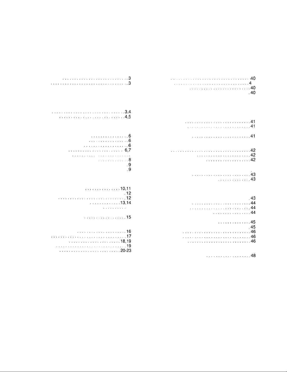
TABLE OF CONTENTS
INTRODUCTION
General description.
Nomenclature
Inspection....................................
INSTALLATION
Handling....................................
Location......................................
Service access
Vibration isolators
REFRIGERANT PIPING
General......................................
Evaporator above condensing unit
Evaporator below condensing unit
Refrigerant piping connections
Liquid line components
Recommended line sizes
Dimensionaldrawings.............
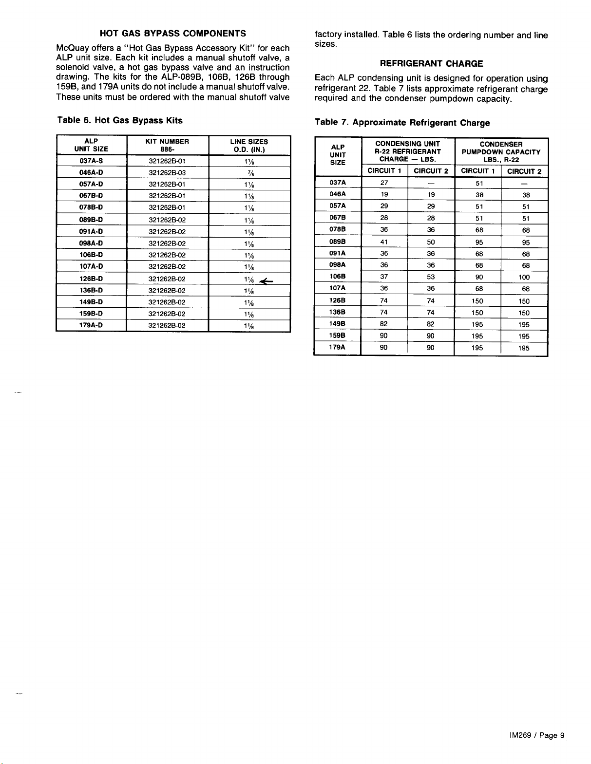
Hot gas bypass components..................
Refrigerant charge..........................
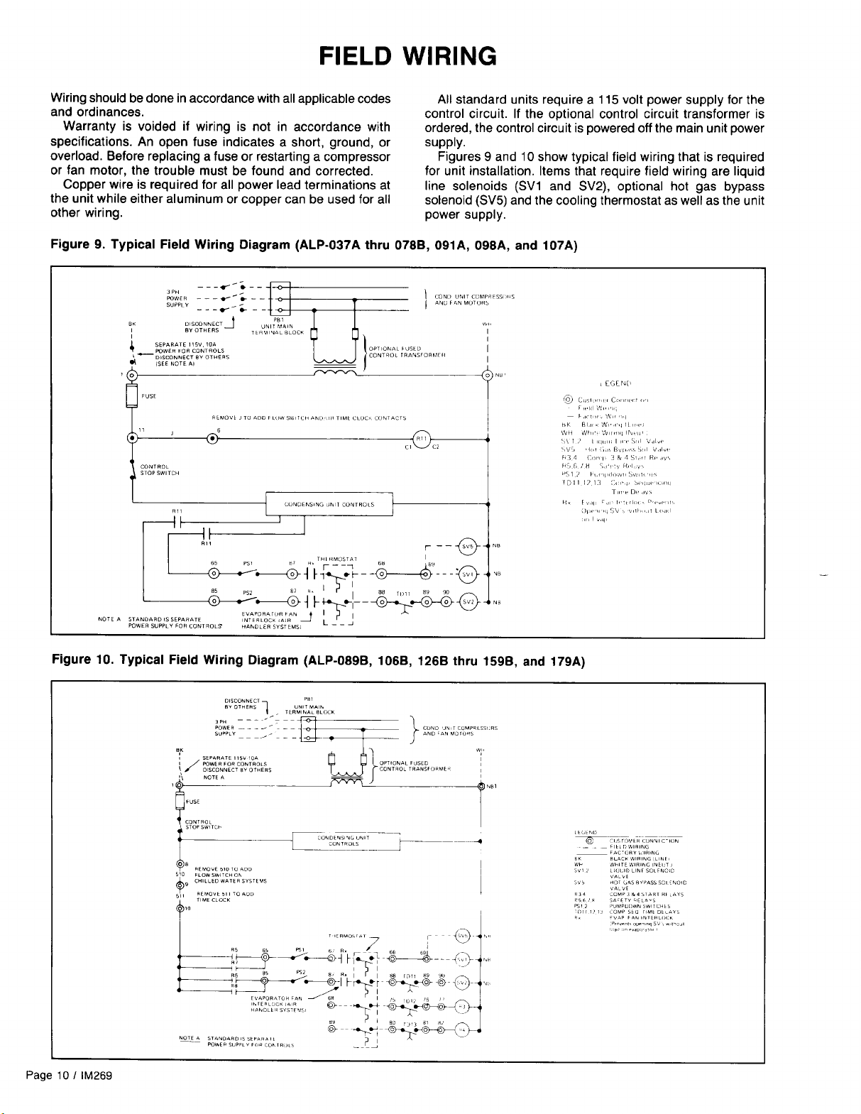
FIELD WIRING
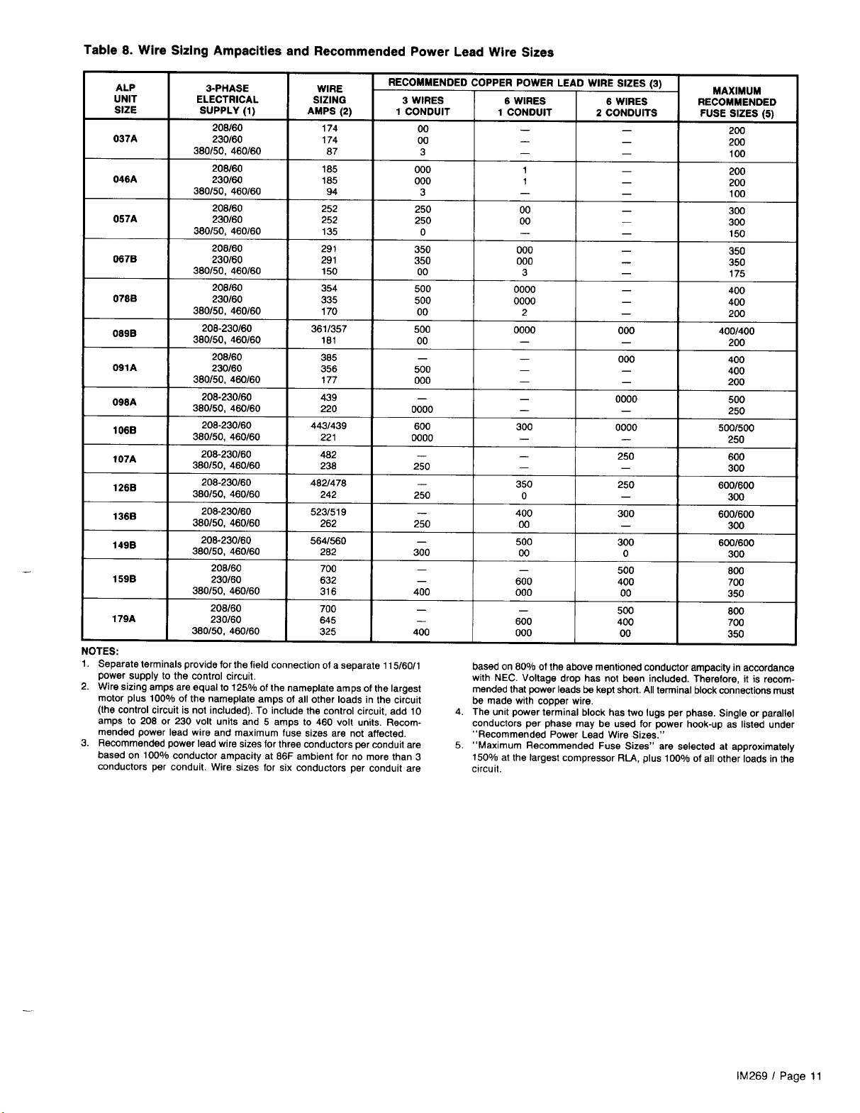
Wire sizing ampacities and
recommended power lead sizes
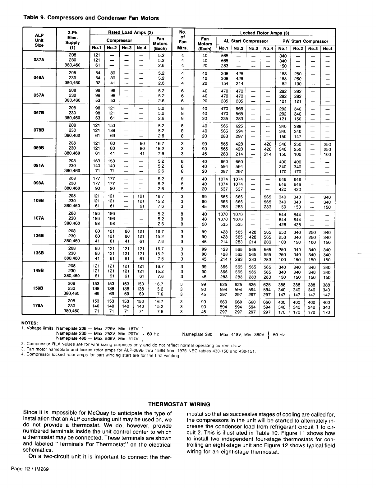
Compressor and condenser fan motors..........
Thermostat wiring
Typical field wiring for thermostats
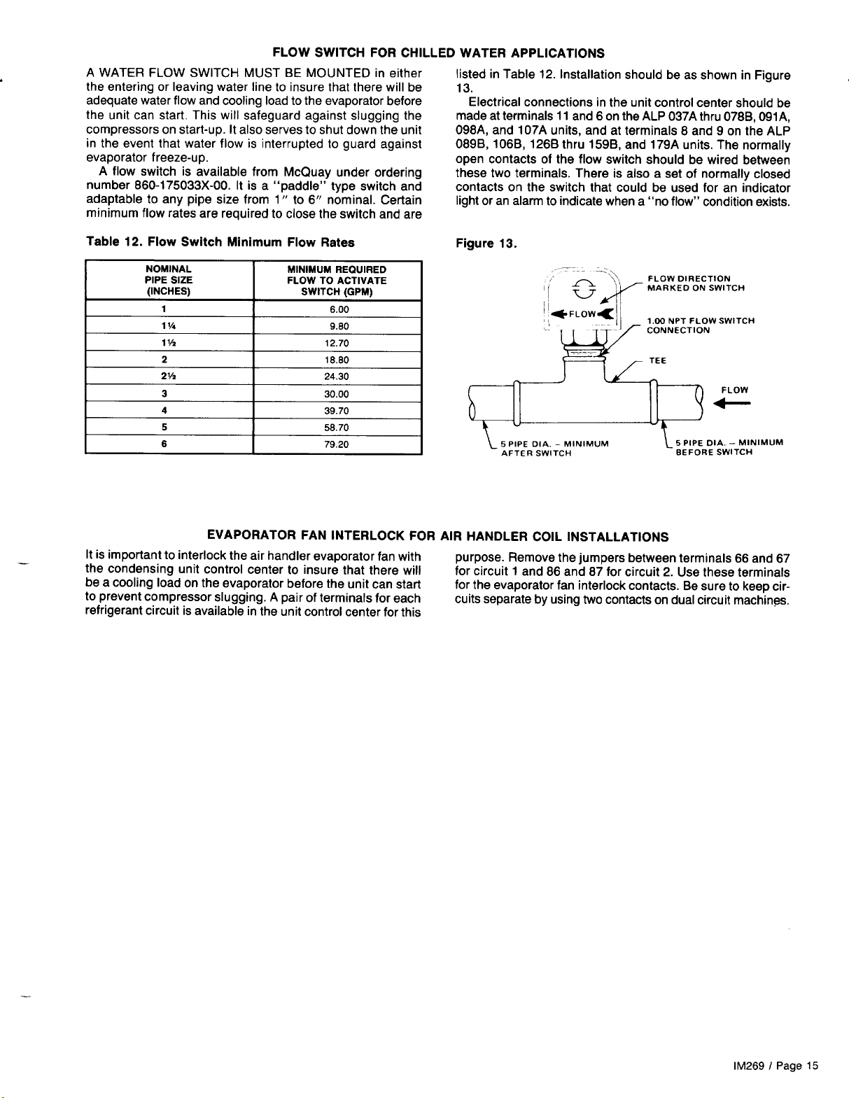
Flow switch for chilled water applications
Evaporator fan interlock
for air handler coil installations
UNIT LAYOUT AND PRINCIPLES OF OPERATION
Major component locations
Control center
Sequence of operation
Electrical legend
Power schematics
Compressor control schematics..............
.........................
...............................
.............................
...........................
...............
...............
.................
.....................
..........
.1:::.:1.11.18
...............
............................
.............
..........
.................
...................
...............................
.....................
..........................
.........................
.3
.3
.3,4
4,5
.6
.6
.6
6,7
.9
.9
10,ll
.12
.12
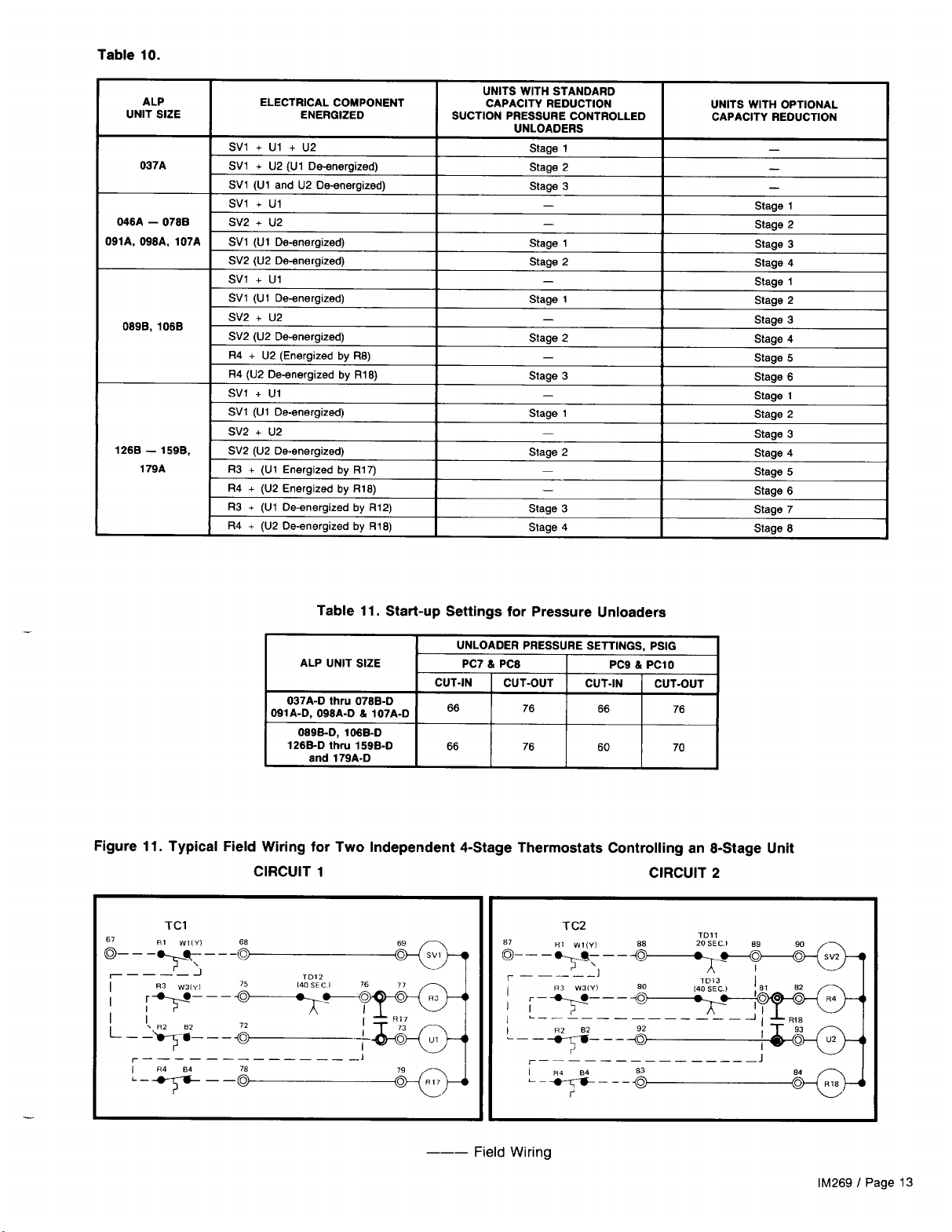
13,14
15
.15
.16
.17
.18,19
.19
.20-23
.24-39
START-UP AND SHUTDOWN
Pre Start-up
.
.
.
.
7
InitialStart-up
Temporary shutdown
Start-up after temporary shutdown..............
Extended shutdown.........................
SYSTEM MAINTENANCE
General...................................
Fanshaftbearings..........................
Electrical terminals
Compressor oil level
Condensers................................
Refrigerant sightglass.
SERVICE
Filter-driers
Liquid line solenoid valve
Thermostatic expansion valve
IN-WARRANTY RETURN MATERIAL PROCEDURE
Copeland compressor.
Components other than compressor
APPENDIX
Standard Controls
Oil pressure safety controls
High pressure control
Low pressure control
FANTROL head pressure control
Optional Controls
SPEEDTROL head pressure control
DAMPERTROL head pressure control...........
Part winding start
Low ambient start
Compressor lockout
Hotgasbypass...........................
TROUBLE SHOOTING CHART.
...
..11::‘:::::::::::::::::::::::..4
.........................
..........................
.......................
........................
.................................
......................
..................
........................
....................
.....................
.........................
..........................
............................
.......................
..................
.............
...............
.............
.40
0
.40
.40
..4 0
41
..4 1
.41
.41
..4 1
.41
.42
.42
.42
.43
.43
.43
.44
.44
.44
.45
.45
.46
.46
.46
..4 7
.48
Page 2 I lM269
“DAMPERTROL”, “FANTROL”,
“McQUAY”,
of McQuay Inc., Minneapolis, Minnesota.
“SEASONPAK”, and “SPEEDTROL” are registered trademarks
Page 3
INTRODUCTION
GENERAL DESCRIPTION
McQuay type ALP SEASONCON air cooled condensing units
are designed for outdoor installations and are compatible with
either air handling or chilled water systems. Each unit is completely assembled and factory wired before evacuation, charging and testing. Each unit consists of twin air cooled condensers with integral subcooler sections, multiple accessible hermetic compressors, complete discharge piping and
suction connections for connection to any air or water cool-
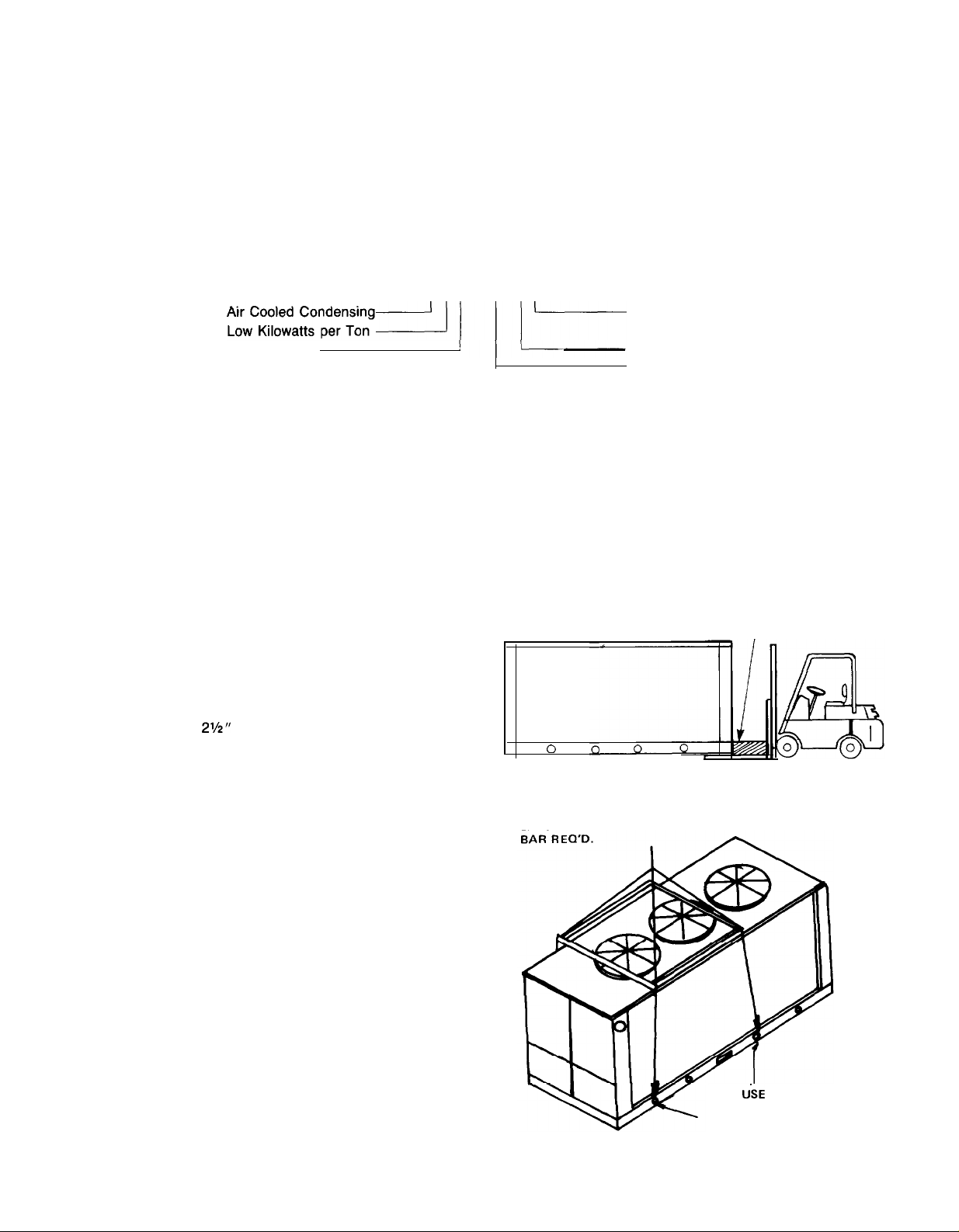
NOMENCLATURE
ALP-089BD
ing evaporator.
The electrical control center includes all safety and
operating controls necessary for dependable automatic
operation except for the cooling thermostat since this is
somewhat depended upon the unit application. Compressors
and fan motors are fused in all three conductor legs and
started by their own three pole contactor.
TTT 1-TT
Refrigerant Circuits
=
Dual; S = Single)
(D
Propeller Fan
INSPECTION
When all the equipment is received, all items should be carefully checked against the bill of lading to insure a complete shipment. All units should be carefully inspected for damage upon arrival. All shipping damage should be reported to the carrier
and a claim should be filed. The unit serial plate should be checked before unloading the unit to be sure that it agrees with
the power supply available.
Design Vintage
Nominal Capacity (Tons)
INSTALLATION
NOTE: Installation and maintenance are to be performed only by qualified personnel who are familiar with local codes
and regulations, and experienced with this type of equipment. CAUTION: Sharp edges and coil surfaces are a potential
injury hazard. Avoid contact with them.
HANDLING
Care should be taken to avoid rough handling or shock due
to dropping the unit. Do not push or pull the unit from anything
other than the base, and block the pushing vehicle away from
the unit to prevent damage to the sheetmetal cabinet and end
frame (see Figure 1).
Never allow any part of the unit to fall during unloaing or
moving as this may result in serious damage.
To lift the unit,
the base of the unit. Spreader bars and cables should be arranged to prevent damage to the condenser coils or unit
cabinet (see Figure 2).
Due to the vertical condenser design, it is recommended that
certain precautions be taken before installation to orient the
unit so that prevailing winds blow parallel to the unit length,
thus minimizing effects on condensing pressure. If it is not
practical to orient the unit in this manner, a wind deflecting
fence should be considered.
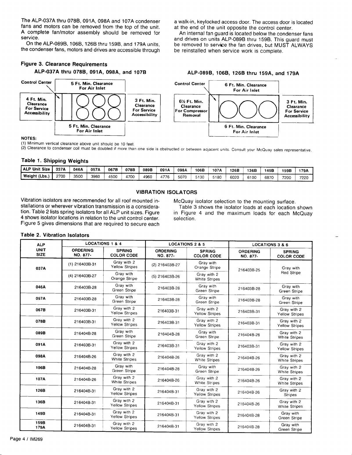
The clearance requirements for these units are given in
Figure 3.
Each end of the unit must be accessible after installation for
periodic service work. Compressors, filter-driers, and manual
liquid line shutoff valves are accessible from the control center
end of the unit through removable access panels on unit sizes
089,106, and 126 through 179 and hinged side access doors
on unit sizes 037 through 078, 091, 098 and 107. All operational, safety, and starting controls are located in the unit control center. Capped connections for field service gauges are
also located inside these enclosures.
CAUTION: Disconnect all power
2V2”
diameter lifting holes are provided in
LOCATION
SERVICE ACCESS
condenser fan drives.
to
the unit while servicing
Figure 1. Suggested Pushing Arrangement
BLOCKING
\
0
Figure 2. Suggested Lifting Arrangement
SPREADER
ACROSS FULL WIDTH
MUST UiE
HOLES FOR ALP-0898 THRU
159B. (NOTE CONTROL BOX
LOCATION.)
THESE RIGGING
REQ’D.
lM269 I
Page 3
Page 4
Page 5
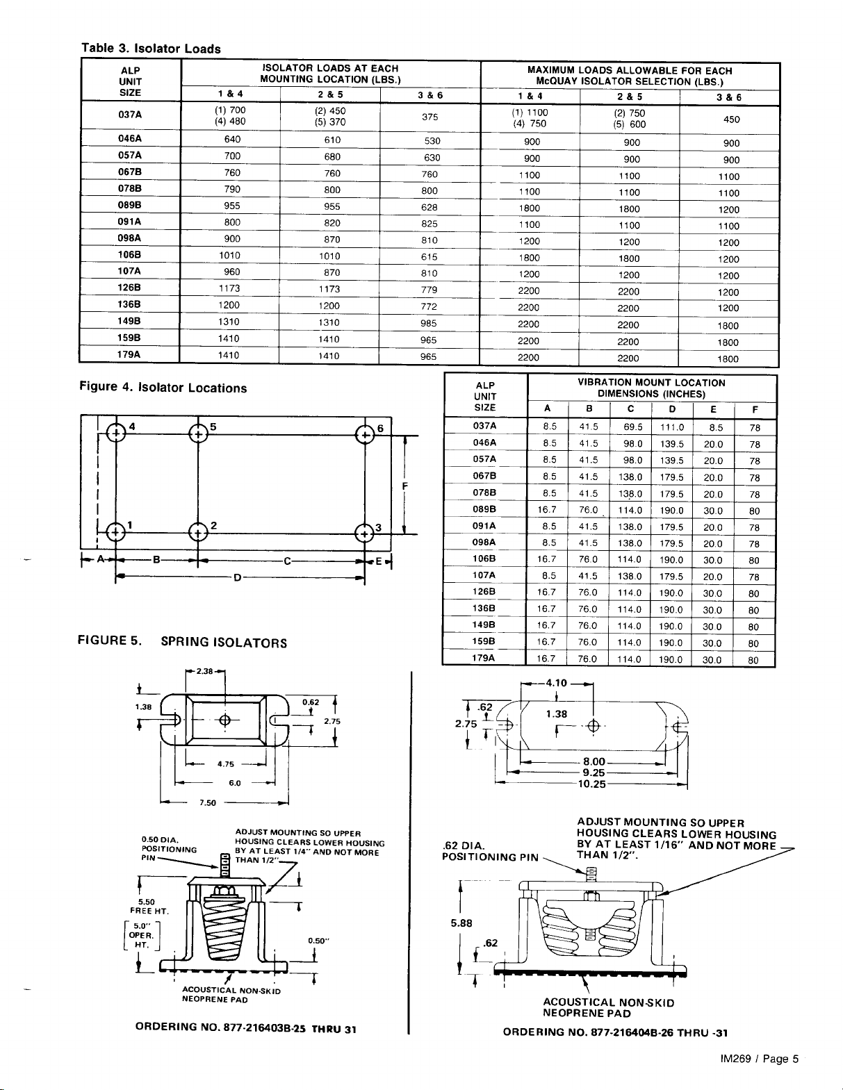
Page 6
REFRIGERANT PIPING
GENERAL
McQuay type ALP condensing units are adaptable to either
chilled water or air handling air conditioning applications, The
only restriction on applications is that the evaporator be
selected for a system using refrigerant 22.
EVAPORATOR ABOVE CONDENSING UNIT
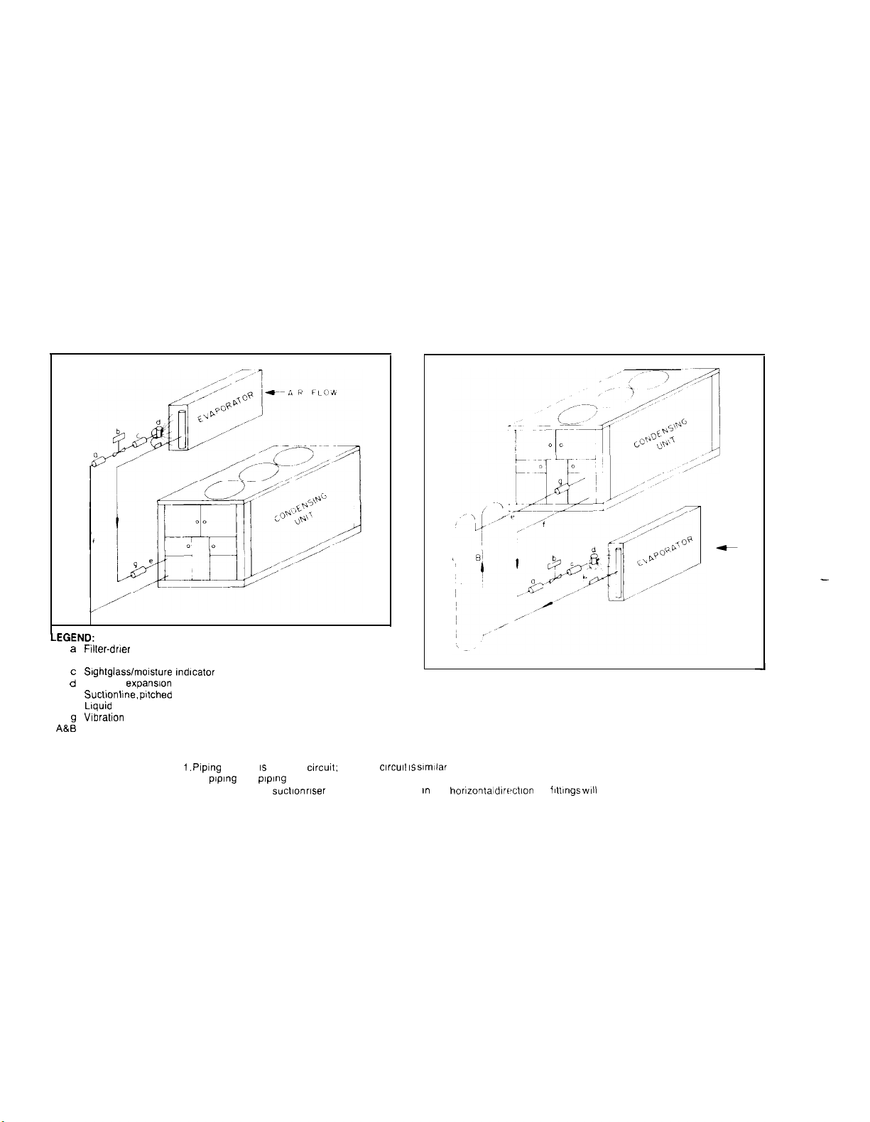
Figure 6 shows an installation where the evaporator is installed above the condensing unit. It is shown for an air handling installation but all components shown are recommended
for chilled water installations, except that a refrigerant
distributor is not usually required for shell-and-tube
evaporators.
EVAPORATOR BELOW CONDENSING UNIT
Figure 7 shows an installation where the evaporator is installed below the condensing unit. It is shown for an air
han-
dling installation, but all components shown are recommended for chilled water installations except that a refrigerant
distributor is not usually required for shell-and-tube
evaporators. Note that a double suction riser is shown for this
arrangement.
Risers “A +
B”
are sized so that their combined
crosssectional Internal area will allow full load unit operation without
excessive pressure drop (see notes, Table 4). Riser
“B”
is
sized to provide adequate suction gas velocity for proper oil
return at minimum load conditions. This riser becomes effective only when the trap shown in riser “A” fills itself with
oil. It should be emphasized that the trap shown in riser “A”
should be designed to contain a minimum internal volume
to keep the total system oil requirements at a minimum. Table
4 gives recommended line sizes for both single and double
suction lines and for liquid lines.
Figure 6. Evaporator Above Condensing Unit
a
Filter-drer
b
Solenoid valve
Slghtglasslmolsture indicator
d”
Thermal
expansion
Suction Ime. pttched
Liquid
line
Vlbratton
absorber
Double suction riser (see Note 3)
A&:
e
f
valve
toward compressor
NOTES:
1. Piping
shown IS for one circut; second
2. All
pIping
3. Trap for double
and pIpIng components are by others
suction riser
clrcult IS slmllar
should be as small in the
Figure 7. Evaporator Below Condensing Unit
horizontal
dlwctlon as ilttlngs
WIII
allow
AIR FLOW
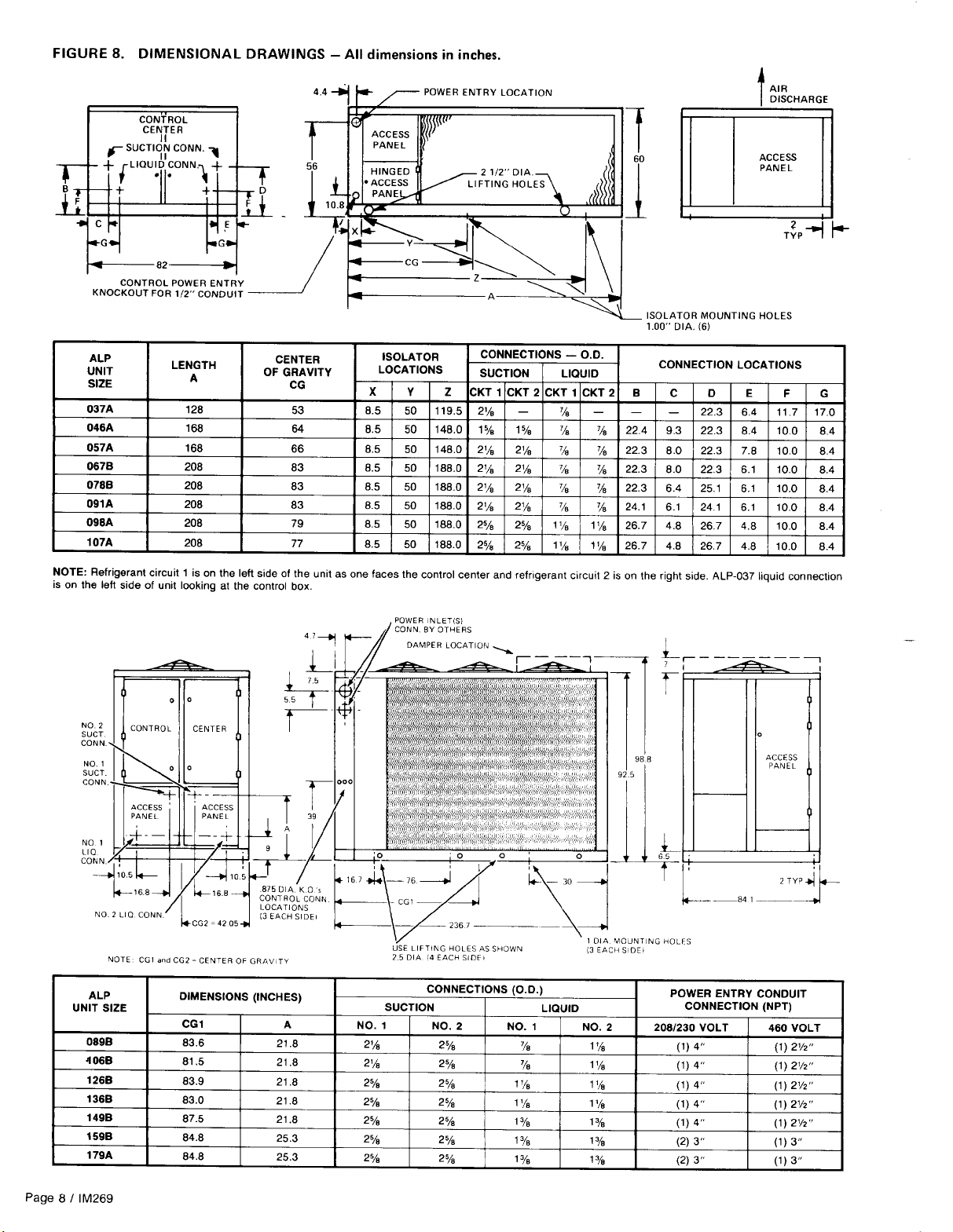
REFRIGERANT PIPING CONNECTIONS
Refrigerant piping connections must be made at the control
center end of the unit. Suction and liquid lines should be
routed through the compressor end access panels on units
ALP-089B, 106B,
1268 thru 1598, and
179A
and out the
tom through the side access panels above the compressor
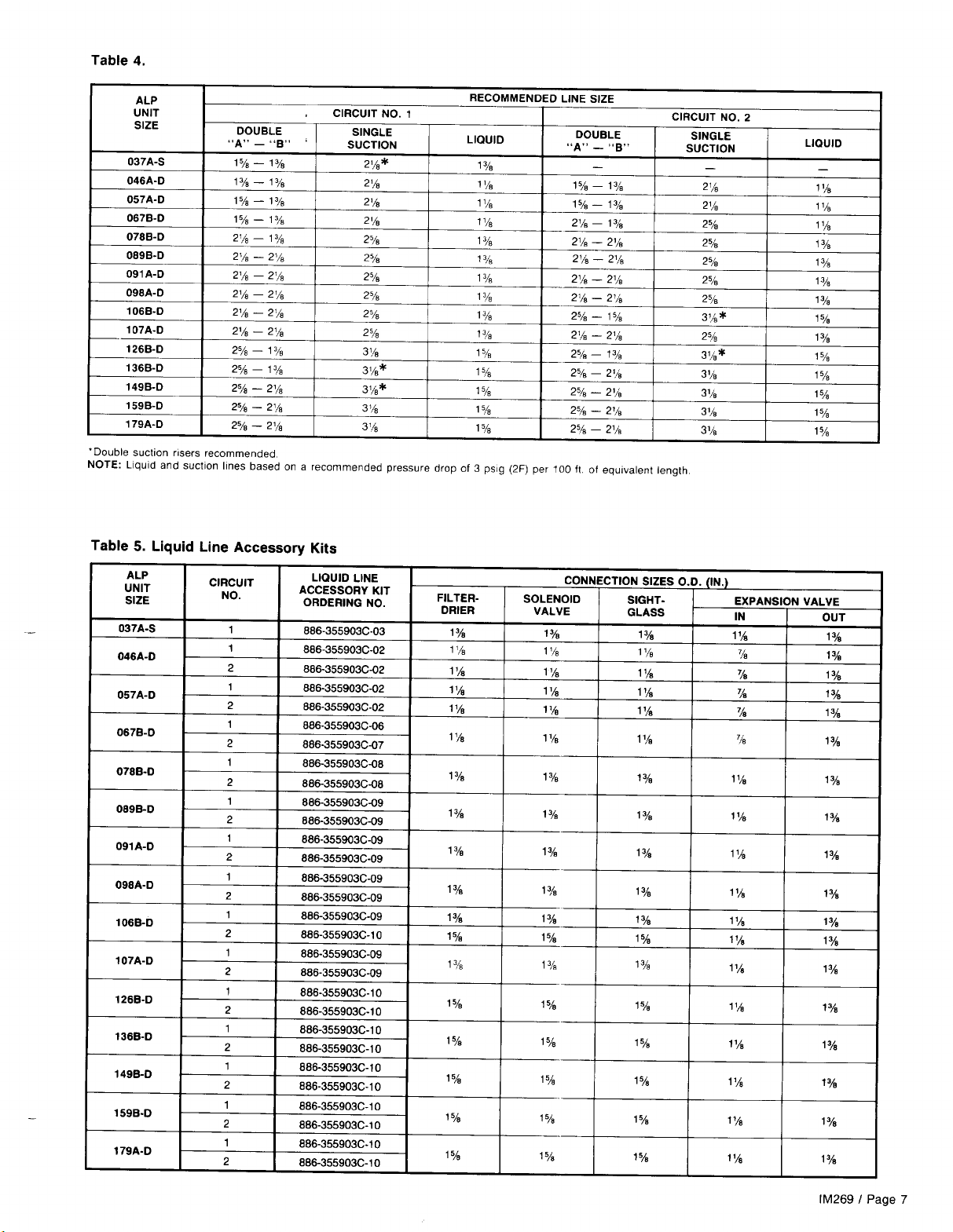
McQuay has available a “Liquid Line Accessory Kit” for each
ALP unit size. Components selected for these kits were
selected on the basis of a total combined pressure drop of
7 psi (includes 100 ft. of tubing). Table 5 shows the ordering
number to be used for each ALP unit size. The components
in these kits are:
Page 6
/
lM269
side access door on units ALP-037A thru
and 107A. When piping, allow room for mounting the
nect
on this same access panel. Figure 8 gives connection
bot-
locations and sizes for all ALP models.
LIQUID LINE COMPONENTS
1.
Replaceable core type filter-driers.
2.
Filter-drier core elements.
Refrigerant solenoid valves.
3.
Refrigerant
4.
Expansion valves (one per circuit).
5.
078B,091A, 098A
discon-
sightglass/moisture indicators.
Page 7
Page 8
Page 9
Page 10
Page 11
Page 12
Page 13
Page 14
Page 15
Page 16

Page 17

Page 18

Figure 18. ALP-089B,
Power into unit
106B,
126B thru
Recommended
field mounted
disconnect
159A, & 179A
switch
SEQUENCE OF OPERATION
For ALP-037A thru 0788, 091A, 098A
&
107A Units:
The components for a two-compressor unit, models
ALP-046A, 057A,
given in parentheses (
The following sequence of operation is for ALP
0678,
078B, 091A,
).
098A and
107A
SEASONCON air cooled condensing unit operation. With control circuit power on, control stop switch
pumpdown
switch
PS1
(PS2) closed (“auto” position), 115
volt power is applied through control circuit fuse
compressor crankcase heater
HTR1
S1
closed, and manual
F1
(HTR2).
When the remote time clock contacts are closed, the flow
switch contacts are closed (chiller applications) and the
manual shutdown switch is on; then relay
R11
is energized,
closing contacts 4 through 6 and 7 through 9. If high pressure
control HP1
pressure control
(HP2),
motor protector
OP1
(OP2) do not sense an alarm condi-
MP1
(MP2) and oil
tion, then the thermostat will energize. The unit will operate
automatically in response to the thermostat.
On a call for cooling,
solenoid
SV1,
opening the valve and allowing refrigerant to
TC1,
stage 1, energizes liquid line
flow into the evaporator. As refrigerant pressure builds up,
low pressure control
tactor Ml, starting the compressor.
LP1
closes to energize compressor
LP1
also energizes condenser fan motor 11 and condenser fan motor controls PC1 2,
TC13, and TC14
(TC14
on models ALP-037 067 and 078).
On two-compressor units, if additional stages of cooling are
required, temperature control thermostat
TC1
energizes liquid line solenoid valve SV2 after time delay relay TD1
sequenced closed, to initiate the same starting sequence in
refrigerant circuit number 2.
On units with compressor unloading, if additional stages
of cooling are required, the unloader
U1
(U2) is de-energized
and the compressor is loaded.
For
ALP-089B, 106B,
1268 thru 1598, & 107A Units
The following sequence of operation is typical for ALP
SEASONCON air cooled condensing unit operation. It is written for a four-compressor unit. Components referred to in the
sequence, but not used in a three-compressor unit are HTR3,
Page 18
/
lM269
Control Center Layout
MP3, R7, TD12, M3 and M7.
With the control circuit power on, control stop switch Sl
are
closed, and manual
closed (“auto” position), 115 volt power is applied through
control circuit fuse Fl to the compressor crankcase heaters
HTR1 and HTR4 and, if safety contacts HP1 and HP2 are
closed, then power is supplied to low pressure switches
and LP2.
to the
When the remote time clock or manual shutdown switch
turns on, a pair of contacts close in the thermostatic circuit.
If all safeties (HP1 and HP2,
through MP4) do not sense an alarm condition, then safety
R5, R7,
relays
plied to the thermostat
automatically in response to TC1.
On a demand for cooling, the unit thermostat energizes
liquid line solenoid
refrigerant to flow into the evaporator. As refrigerant pressure
builds up, low pressure control
pressor contactor Ml, starting the compressor.
energizes
con-
tactors Ml 1, Ml2 and M13. A second contact on R9 shuts
out TD15, opening up TD15. If
R9,
then compressors 1 and 3 cannot be started until TD15
times out and energizes safety relays
NOTE: The new motor protectors have a two-minute time
delay. When power is interrupted to terminals 3 and 4 of any
1 has
motor protector, the MP contacts across terminals 1 and 2
will not close for two minutes.
If additional stages of cooling are required, the thermostat
energizes liquid line solenoid valve SV2 after time delay relay
TD11
has sequenced closed, to initiate the same starting se-
quence in refrigerant circuit number 2.
If additional cooling is still required, the third and fourth
stages of the thermostat energize the third and fourth com-
pressors after time delay relays TD12 and TD13 have sequenced closed.
pumpdown
switches PS1 and PS2
OP1
through OP4 and
R6 and R8 are energized. Power is then sup-
TC1
and the unit will operate
SV1,
opening the valve and allowing
LP1
closes, energizing com-
R9
which in turn provides power to fan motor
LP1
opens, cutting power to
R5
and R7.
LP1
LP1
MP1
also
con-
Page 19

Page 20

Page 21

Page 22

Page 23

Page 24

Page 25

Page 26

Page 27

Page 28

Page 29

Page 30

Page 31

Page 32

Page 33

Page 34

Page 35

Page 36

Page 37

Page 38

Page 39

Page 40

START-UP AND SHUTDOWN
1.
With all electrical disconnects open, check all screw or
lug type electrical connections to be sure they are tight
for good electrical contact. Check all compressor valve
connections for tightness to avoid refrigerant loss at startup. Although all factory connections are tight before shipment, some loosening may have resulted from shipping
vibration.
2.
On chilled water installations, check to see that all water
piping is properly connected.
Check the compressor oil level. Prior to start-up, the oil
3.
level should cover at least one-third of the oil sightglass.
4.
Remove the eight (8) compressor shipping blocks that
are attached to the compressor rails and the base of the
unit. Units ALP-037 through 078, 091, 098 and 107 do
not have shipping blocks.
Check the voltage of the unit power supply and see that
5.
it is within the
voltage unbalance must be within * 2%.
Check the unit power supply wiring for adequate
6.
ty and a minimum insulation temperature rating of 75C.
f
10% tolerance that is allowed. Phase
ampaci-
PRE START-UP
7.
2.
9.
10.
11.
CAUTION: Most relays and terminals in the unit control center
are hot with S1 and the control circuit disconnect on.
Verify that all mechanical and electrical inspections have
been completed per local codes.
See that all auxiliary control equipment is operative and
that an adequate cooling load is available for initial
start-up.
Open the compressor suction and discharge shutoff
valves until backseated. Always replace valve seal caps.
Making sure control stop switch
pumpdown
pumpdown,” throw the main power and control discon-
nect switches to “on.”
heaters. Wait a minimum of 12 hours before starting up
unit.
Open all water flow valves and start the chilled water
pump. Check all piping for leaks and vent the air from
the evaporator and system piping to obtain clean, non-
corrosive water in the evaporator circuit.
switches
PS1
and PS2 are on “manual
This will energize crankcase
S1
is open (off) and
INITIAL START-UP
1.
Double check that the compressor suction and discharge
shutoff valves are backseated. Always replace valve seal
caps.
2.
Open the manual liquid line shutoff valve at the outlet of
the subcooler.
3.
Check to see that
in the “manual pumpdown” position. Throw the control
stop switch
4.
Adjust the dial on the temperature controller to the desired
chilled water or leaving air temperature.
5.
Allow the crankcase heaters to operate for at least 12
hours prior to start-up.
Move
pumpdown
turn off the chilled water pump or evaporator fan. It is especially important on chilled water installations that the compressors
pump down before the water flow to the evaporator is interrupted to avoid freeze-up.
1. Start the chilled water pump or evaporator fan.
2. With control stop switch
postion.
3. Observe the unit operation for a short time to be sure that the compressors do not cut out on low oil pressure.
pumpdown
S1
to the “on” position.
switches PS1 and PS2 to the “manual pumpdown” position. After the compressors have pumped down,
switches
S1
in the “on” position, move
PS1
and PS2 are
TEMPORARY SHUTDOWN
START-UP AFTER TEMPORARY SHUTDOWN
pumpdown
Start the auxiliary equipment for the installation.
Start the system by moving
PS2 to the “automatic pumpdown” position.
After running the unit for a short time, check the oil level
in each compressor crankcase and check for flashing in
the refrigerant sightglass (see “Maintenance”, page 41).
After system performance has stabilized, it is necessary
that the “Compressorized Equipment Warranty Form”
(Form No. 206036A) be completed to obtain full warranty
benefits. This form is shipped with the unit and after completion should be returned to
through your sales representative.
switches
PS1
and PS2 to the “automatic pumpdown”
pumpdown
McQuay
switches PS1 and
Service Department
(For start-up after extended shutdown, refer to applicable “Initial Start-up” steps.)
1. Close the manual liquid line shutoff valves.
2. After the compressors have pumped down, turn off the
chilled water pump or evaporator fan.
3. Turn off all power to the unit and to the auxiliary
equipment.
Page
40 / lM269
EXTENDED SHUTDOWN
4.
Move the control stop switch S1 to the “off” position.
5.
Close the compressor suction and discharge valves.
6.
Tag all opened disconnect switches to warn against start-
up before opening the compressor suction and discharge
valves.
Page 41

SYSTEM MAINTENANCE
GENERAL
On initial start-up and periodically during operation, it will be
necesasry to perform certain routine service checks, Among
these are checking the compressor oil level and taking
densing,
the oil level should be visible in the oil sightglass with the
compressor running. On units ordered with gauges,
sing, suction, and oil pressures can be read from the unit
suction and oil pressure readings. During operation,
con-
conden-
con-
trol center. The gauges are factory installed with a manual
shut-off valve on each gauge line. The valves should be
closed at all times except when gauge readings are being
taken. On units ordered without gauges, the gauge shutoff
valves come factory installed inside the unit control center
for convenient connection of service gauges from outside the
unit.
ALP-089B, 106B,
The fan shaft bearings do not require lubrication at the time the unit is put into service. The fan shaft bearings should be
greased once a year using Standard Oil Company
CAUTION: ELECTRIC SHOCK HAZARD. TURN OFF ALL POWER
BEFORE CONTINUING WITH THE FOLLOWING SERVICE.
All power electrical terminals should be retightened every six months, as they tend to loosen in service due to normal heating
and cooling of the wire.
Because of the large refrigerant charge required in an air
cooled condensing unit, it is usually necessary to put additional oil into the system. The oil level should be watched
carefully upon initial start-up and for sometime thereafter.
At the present time, Suniso No. 3GS oil is the only oil approved by Copeland for use in these compressors. The oil
level should be maintained at about one-third of the sightglass
on the compressor body.
Oil may be added to the
oil fill hole in the crankcase and to the Sundstrand compressor
through the
To add oil, isolate the crankcase and pour or pump the
necessary oil in. If the system contains no refrigerant, no
318”
process tube on the side of the compressor.
Copeland
compressor through the
FAN SHAFT BEARINGS
126B thru
Amco
Multi-Purpose Lithium Grease. DO NOT OVERLUBRICATE.
ELECTRICAL TERMINALS
COMPRESSOR OIL LEVEL
159B,
and 179A
special precautions are necessary other than keeping the oil
clean and dry.
If the system contains a refrigerant charge, close the suction valve and reduce crankcase pressure to 1 to 2 psig. Stop
the compressor and close the discharge valve.
Add the required amount of oil. During the period the compressor is exposed to the atmosphere, the refrigerant will
generate a vapor pressure, retarding the entrance of contaminants. Before resealing the compressor, purge the
crankcase by opening the suction valve slightly for 1 or 2
seconds. Close the oil port, open the compressor valves and
restore the system to operation.
CONDENSERS
Condensers are air cooled and constructed of
per tubes bonded in a staggered pattern into rippled
aluminum fins. No maintenance is ordinarily required except
the occasional removal of dirt and debris from the outside
The refrigerant sightglasses should be observed periodical-
ly.
(A monthly observation should be adequate.) A clear glass
of liquid indicates that there is adequate refrigerant charge
in the system to insure proper feed through the expansion
valve. Bubbling refrigerant in the sightglass indicates that the
system is short of refrigerant charge. On sightglasses ordered
3/8”0.0. cop-
REFRIGERANT SIGHTGLASS
surface of the fins. Care should be taken not to damage the
fins during cleaning. Periodic use of the purge valve on the
condenser will prevent the buildup of non-condensables.
from McQuay as part of the “Liquid Line Accessory Kits”
listed on page 6, an element inside the sightglass indicates
what moisture condition corresponds to a given element color.
If the sightglass does not indicate a dry condition after a few
hours of operation, the unit should be pumped down and the
cores in the filter-drier changed.
lM269 /
Page
41
Page 42

SERVICE
NOTE: Service on this equipment is to be performed by qualified refrigeration service personnel. Causes for repeated
tripping of safety controls must be investigated and corrected. CAUTION: Disconnect ail power before doing any service inside the unit.
FILTER-DRIERS
To change the filterdrier core(s), pump the unit down by
ing
pumpdown
switches
PS1
and PS2 to the “manual
down” position. Turn off all power to the unit and install
jumpers across the terminals shown in the table below.
ALP CIRCUIT JUMPER ACROSS
UNIT SIZE
037
thru
076, 091, 098 107
037
thru
076, 091, 09.9, 107
099,106,
069, 106, 126
126th~
thru
NUMBER
179
179
1
2
1
2
TERMINALS
114
214
114 to 118
214 to 218
LIQUID LINE SOLENOID VALVE
The liquid line solenoid valves, which are responsible for
automatic pumpdown during normal unit operation, do not
normally require any maintenance. They may, however, require replacement of the solenoid coil or of the entire valve
assembly.
The solenoid coil may be removed from the valve body
without opening the refrigerant piping by moving
switches PS1 and PS2 to the “manual pumpdown” position.
mov-
pump-
to
116
to
216
pumpdown
Turn power to the unit back on and restart the unit by mov-
ing
pumpdown
switches
PS1
and PS2 to the “automatic
pumpdown” position. Close the manual liquid line shutoff
valve(s) and when evaporator pressure reaches 0 psig, move
the control stop switch
S1
to the “off” position. This will close
the liquid line solenoid valve(s) and isolate the short section
of refrigerant piping containing the filter-drier(s). Remove the
cover plate from the filter-drier shell and replace the core(s).
After core replacement, replace the cover plate. A leak
check around the flange of the filter-drier shell is
recom-
mended after the cores have been changed.
The coil can then be removed from the valve body by simply
removing a nut or snap-ring located at the top of the coil. The
coil can then be slipped off its mounting stud for replacement.
Be sure to replace the coil on its mounting stud before
ing
pumpdown
switches
PS1
and PS2 to the “automatic
return-
pumpdown” position.
To replace the entire solenoid valve, the unit must be
pumped down by use of the manual liquid line shutoff valve.
THERMOSTATIC EXPANSION VALVE
The expansion valve is responsible for allowing the proper
amount of refrigerant to enter the evaporator regardless of
cooling load. it does this by maintaining a constant superheat.
(Superheat is the difference between refrigerant temperature
as it leaves the evaporator and the saturation temperature
corresponding to the evaporator pressure.) Typically,
superheat should run in the range of 1 OF to 15F. On valves
purchased through McQuay, the superheat setting can be
adjusted by removing a cap at the bottom of the valve to
expose the adjustment screw. Turn the screw clockwise (when
viewed from the adjustment screw end) to increase the
INLET
superheat setting and counterclockwise to reduce superheat.
Allow time for system rebalance after each superheat adjustment.
The expansion valve, like the solenoid valve, should not
normally require replacement, but if it does, the unit must
be pumped down by using the manual liquid line shutoff valve.
If this problem can be traced to the power element only, it
can be unscrewed from the valve body without removing the
valve, but only after pumping down the unit with the liquid
line shutoff valves.
POWER ELEMENT
(CONTAINS DIAPHRAGM)
OUTLET
SPRING
Page 42
/
lM269
ADJUSTMENT SCREW
CAP
Page 43

IN-WARRANTY RETURN MATERIAL PROCEDURE
COMPRESSOR
Copeland
who maintain a stock of replacement compressors and service parts to serve refrigeration contractors and servicemen.
sales representative, or McQuay Warranty Claims Department at the address on the cover of this bulletin. You will be
authorized to exchange the defective compressor at a
Copeland
tained. A credit is issued to you by the wholesaler for the
returned compressor after
inoperative compressor. If that compressor is out of
Copeland’s warranty, a salvage credit only is allowed. Pro-
Material may not be returned except by permission of
authorized service personnel of McQuay Inc. at Minneapolis,
Minnesota. A “Return Goods” tag will be sent to be included with the returned material. Enter the information as
called for on the tag in order to expedite handling at our factories and prompt issuance of credits.
replacement. Therefore, a purchase order must be entered
through your nearest McQuay representative. The order
Refrigeration Corporation has stocking wholesalers
When a compressor fails in warranty, contact your local
wholesaler, or an advance replacement can be ob-
Copeland
factory inspection of the
COMPONENTS OTHER THAN COMPRESSORS
The return of the part does not constitute an order for
vide McQuay with full details: McQuay unit model and unit
serial numbers. Include the invoice and the salvage value
credit memo copies and we will reimburse the difference. In
this transaction, be certain that the compressor is definitely
defective. If a compressor is received from the field that tests
satisfactorily, a service charge plus a transportation charge
will be charged against its original credit value.
On all out-of-warranty compressor failures, Copeland offers the same field facilities for service and/or replacement
as described above. The credit issued by Copeland on the
returned compressor will be determined by the repair charge
established for that particular unit.
should include part name, part number, model number and
serial number of the unit involved.
Following our personal inspection of the returned part, and
if it is determined that the failure is due to faulty material or
workmanship, and in warranty, credit will be issued on
customer’s purchase order.
All parts shall be returned to the pre-designated McQuay
factory, transportation charges prepaid.
APPENDIX: STANDARD CONTROLS
NOTE: PERFORM AN OPERATIONAL CHECK OF ALL UNIT SAFETY CONTROLS ONCE PER YEAR.
OIL PRESSURESAFETY CONTROL
The oil pressure safety control is a manually resettable device
which senses the differential between oil pressure at the
discharge of the compressor oil pump and suction pressure
inside the compressor crankcase. When the oil pressure
reaches approximately 15 PSI above the crankcase suction
pressure, the pressure actuated contact of the control opens
from its normally closed position. If this pressure differential
cannot be developed, the contact will remain closed and
energize a heater element within the control. The heater ele-
ment warms a normally closed bimetallic contact and causes
the contact to open, de-energizing a safety relay and break-
ing power to the compressor.
It takes about 120 seconds to warm the heater element
enough to open the bimetallic contact, thus allowing time for
the pressure differential to develop.
If during operation, the differential drops below 10 PSI, the
heater element will be energized and the compressor will
stop. The control can be reset by pushing the reset button
on the control. If the compressor does not restart, allow a few
LINE (SEE NOTE
LINE
(SEE
11
ACTUATED
CONTACT
NOTE
21
L M
minutes for the heater element and bimetallic contacts to cool
and reset the control again.
To check the control, pump down and shut off all power
to the unit. Remove the compressor fuses, and install a
voltmeter between terminals
“L”
and
“M”
of the oil pressure
control. Turn on power to the unit control circuit (separate
disconnect or main unit disconnect, depending on the type
of installation). Check to see that the control stop switch
is in the “on” position. The control circuit should now be
energized, but with the absence of the compressor fuses, no
oil pressure differential can develop and thus, the pressure
actuated contacts of the control will energize the heater ele-
ment and open the bimetallic contacts of the control within
120 seconds. When this happens, the safety relay is
energized, the voltmeter reading will rise to
115V,
and the
compressor contactor should open. Repeated operations of
the control will cause a slight heat buildup in the bimetallic
contacts, resulting in a slightly longer time for reset with each
successive operation.
-
t
-
BIMETALLIC CONTACTS
HEATER ELEMENT
NEUTRAL
NEUTRAL
SAFETY RELAY
S1
de-
NOTES: 1. Hot only when the unit thermostat calls for compressor
to run.
2.
Hot only when other
safety
control contacts are closed.
lM269
/ Page 43
Page 44

HIGH PRESSURE CONTROL
The high pressure control is a single pole pressure activated
switch that opens on a pressure rise to de-energize the
entire control circuit except for compressor crankcase heaters.
It senses condenser pressure and is factory set to open at
380 psig and can be manually reset closed at 315 psig. To
check the control, either block off condenser surface or start
the unit with fuses in only one fan fuse block
(FBll)
and
observe the cut-out point of the control by watching condenser
LOW PRESSURE CONTROL
The low pressure control is a single pole pressure switch that
closes on a pressure rise. It senses evaporator pressure and
is factory set to close at 60 psig and automatically open at
25 psig. The control has an adjustable range of 20 inches
of Hg. to 100 psig and an adjustable differential of 6 to 40
psig. To check the control (unit must be running), move the
pumpdown
switch(es) PSI and PS2 to the “manual
pump-
down” position. As the compressor pumps down, condenser
pressure rise. The highest point reached before cut-out is the
cut-out setting of the control.
CAUTION: Although there is an additional pressure relief
device in the system set at 450 psig, it is highly
recom-
mended that the “control stop” switch S1 be close at hand
in case the high pressure control should malfunction.
pressure will rise and evaporator pressure will drop. The
lowest evaporator pressure reached before cut-out is the cutout setting of the control. By moving the pumpdown switch(es)
PS1
and PS2 to the “automatic pumpdown” position,
evaporator pressure will rise. The highest evaporator pressure
reached before compressor restart is the cut-in setting of the
control.
FANTROL
-
HEAD
FANTROL is a method of head pressure control which
automatically cycles the condenser fans in response to condenser pressure and ambient air temperature. This maintains
head pressure and allows the unit to run at low ambient air
temperatures.
For ALP-037A thru 0788,
Models ALP-037A thru 0788,
dual independent circuits with the fans for circuit 1 (fans
091A,
098A,
091A, 098A,
107A:
and
107A
have
11,
12, 13, 14) and circuit 2 ( fans 21, 22, 23, 24) being controlled independently by the condensing pressure and ambient air of each circuit. Fans 11 and 21 start with each compressor and fans 12 and 22 cycle on and off in response to
condenser pressure. The cut-out and cut-in pressures are
Table 13. Factory FANTROL Settings
UNIT SIZE
ALP-OBSB, 106B
1268
thru
159B,
&
l?QA
I
270 psi’ 170 psi’
-
-
8OFt
PRESSURE CONTROL
given in Table 13. Fans 13 and 14, circuit 1, and fans 23 and
24, circuit 2, are controlled by ambient temperature and are
factory set at the values given in Table 13. Note that the
number of fans on each unit varies.
For ALP-089B,
106B, 126B
thru
159B,
and
179A:
The first fan (11) is started when the first compressor in the
unit starts. Fan 12 is controlled by parallel wired pressure
switches which sense condenser pressure in circuit 1 and
2. The third fan (13) is controlled by parallel wired temperature
switches, one of which senses condenser inlet air for circuit
1 and the other senses condenser inlet air for circuit 2. Refer
to Table 13 for cut-out and cut-in settings of these controls.
CONDENSER FAN
70Ft
-
- - -
I
l PC1 and PC2
Page 44 I lM269
t
TC5 and TC6
Page 45

APPENDIX: OPTIONAL CONTROLS
SPEEDTROL -HEAD PRESSURE CONTROL
ALP-037A thru
The SPEEDTROL system of head pressure control operates
in conjunction with FANTROL by modulating the motor speed
on fans 11 and 21 in response to condensing pressure. By
reducing the speed of the last fan as the condensing pressure
falls, the unit can operate at lower ambient temperatures.
The SPEEDTROL fan motor is a single phase,
thermally protected motor specially designed for variable
speed application. The solid-state speed controls SC1 1 and
DAMPERTROL
ALP-089B, 1068, 1268 thru 1598, and
DAMPERTROL is an optional system for reducing condenser
capacity. It consists of an assembly of damper blades,
linkages and blade operators installed over the first fan
turned on by FANTROL (fan 11) and arranged to operate as
shown. The blade operators sense condenser pressure and
extend or contract in response to the pressure to open or
close the damper blades as reuired to maintain adequate condenser pressure. The operators are factory set to begin open-
ing the damper blades at 170 + 5 psig and to be fully open
at 250 + 10 psig.
208/240
078B,
091A, 098A and 107A
SC21 are mounted inside the compressor compartment near
the top of the condenser coils, Units with 460 volt power have
a transformer mounted on the back of the control box to step
the voltage down to 230 volts for the SPEEDTROL motor.
volt,
-
HEAD PRESSURE CONTROL
speed at approximately 230 psig and maintains a minimum
condensing pressure of 170 to 180 psig.
unit should be started with the fuses removed from fans 11
and 13 (on three-fan units only). At condenser pressures
below 170
ly closed. As pressure rises above 170 + 5 psig, the damper
blades should begin opening and be fully open at 250 f 10
psig. Leaving the fuses in on fan 12 will prevent head pressure
from becoming excessive, since this fan will start after the
fully open setting of the damper operators has been observed.
The SPEEDTROL control starts to modulate the motor
179A
To check the damper blade operator pressure settings, the
+
5 psig, the damper blades should be complete-
DAMPER
SECTION
y
COIL
DAMPERTROL IN OPEN POSITION
Part winding start is available on all voltage units and
sists of a solid-state time delay wired in series with the
tactor that energizes the second winding of each compressor Control checkout is best accomplished by observation as
motor. Its purpose is to limit current inrush to the compressors
upon start-up. As each compressor starts, the contactor for occurs before the second contactor pulls in.
LINE
1
PART WINDING START (OPTIONAL)
con-
con-
DAMPERTROL IN CLOSED POSITION
the first motor winding is energized instantly while that for
the second motor winding is delayed for 1 second.
each contactor is pulled in to see that the 1 second delay
PART WINDING
(2nd MOTOR
WINDING)
lM269
/
Page 45
Page 46

LOW AMBIENT START (OPTIONAL)
Low ambient start is available on all units as an option with
FANTROL and included automatically with optional
TROL or DAMPERTROL. It consists of a solid-state normal-
ly closed time delay wired in series with a relay. These are
both wired in parallel to the liquid line solenoid valve so that
when the solenoid valve is energized by the unit thermostat,
the low ambient start relay is also energized through the time
delay. The relay has contacts that essentially short-circuit the
low pressure control and allow the compressor to start with
the low pressure control open.
After about
energize the relay. If the system has not built up enough
evaporator pressure to close the low pressure control, the
compressor will stop. The time delay can be reset to its
2% minutes, the time delay will open and
SPEED-
de-
original normally closed position by moving the
switch(es)
tion. Moving the
pumpdown” position will again energize the relay for another
attempt at start-up. If the system has built up enough
evaporator pressure, the compressor will continue to run.
To check the control, turn off all power to the unit and
remove the wire(s) leading to the terminals of the low pressure
control(s) LPI and LP2. Remove the compressor fuses and
jumper across terminals
and oil pressure safety control(s). Energize the control circuit by turning on the control circuit disconnect or main power
disconnect (depending on the installation) and the control stop
switch
PS1
or PS2 to the “manual pumpodown” posi-
pumpdown
S1.
The compressor
switch back to the “automatic
“L”
and
“M”
of the freeze control(s)
contactors
should pull in instantly.
pumpdown
f
L,NE
NOTE :
COMPRESSOR LOCKOUT (OPTIONAL)
Compressor lockout consists of a solid-state time delay wired
in series with the compressor contactor( It purpose is to
prevent rapid compressor cycling when cooling demands are
erratic. The circuit illustrated below is for the lead compressor
in each refrigerant circuit. The circuit for the second compressor(s) performs the same function but is wired differently (see unit wiring diagram).
When the unit thermostat no longer calls for cooling and
the compressor contactor have opened, the lockout time
delay breaks open the circuit, preventing compressor restart.
The circuit remains open for a period of 5 minutes so that
if the unit thermostatshould call for cooling before the delay
period has expired the compressor will not restart. After 5
minutes, the time delay will close its contacts to complete
Line is only hot when the unit thermostat calls for compressor to run.
Low
*zzA:%lEUTRAL
-
ALP-937A thru 078B,
the circuit and be ready for start-up. The time delay opens
its contacts whenever power to terminal 4 is interrupted and
resets closed automatically after the time delay period.
To check the control, the compressor(s) must be running
initially. Move the
“manual pumpdown” position. Immediately after the compressor(s) have stopped running, move the pumpdown switch
back to the “automatic pumpdown” position. The lead compressor should not restart for 5 minutes. The second compressor in the refrigerant circuit should start approximately
20 seconds after the lead compressor, provided that the cooling load is high enough to require it. Each refrigerant circuit
can be checked the same way.
091A,
pumpdown
098A, 107A
switch PSI or PS2 to the
Page
46 I
lM269
NOTE:
1 C&P
TO UNIT THERMOSTAT
Hot whenever freeze control and high
pressure control permit safe operation.
LOCKOUT
TIME DELAY
Page 47

HOT GAS BYPASS (OPTIONAL)
Hot gas bypass is a system for maintaining evaporator
pressure at or above a minimum value. The purpose for doing this is to keep the velocity of the refrigerant as it passes
through the evaporator high enough for proper oil return to
the compressor when cooling load conditions are light. Hot
gas bypass kits are described on page 9.
The solenoid valve should be wired to open whenever the
unit thermostat calls for the first stage of cooling (see Figure
11). The pressure regulating valve that
McQuay
offers is factory set to begin opening at 58 psig (32F for R-22) when the
air charged bulb is in an
80F
ambient temperature. The bulb
can be mounted anywhere as long as it senses a fairly constant temperature at various load conditions. The compressor
suction line is one such mounting location. It is generally in
the 50F to 60F range. The chart on page 47 indicates that
when the bulb is sensing 50F to 60F temperatures, the valve
will begin opening at 54 to 56 psig. This setting can be
changed as indicated above, by changing the pressure of the
air charge in the adjustable bulb. To raise the pressure set-
ting, remove the cap on the bulb and turn the adjustment
screw clockwise. To lower the setting, turn the screw
counterclockwise. Do not force the adjustment beyond the
range for which it is designed, as this will damage the ad-
justment assembly.
The regulating valve opening point can be determined by
slowly reducing the system load while observing the suction
pressure. When the bypass valve starts to open, the
refrigerant line on the evaporator side of the valve will begin
to feel warm to the touch.
CAUTION: The hot gas line may become hot enough to cause
injury in a very short time so care should be taken during valve
checkout.
On installations where the condensing unit is remote from
the evaporator, it is recommended that the hot gas bypass
valve be mounted near the condensing unit to minimize the
amount of refrigerant that will condense in the hot gas line
during periods when hot gas bypass is not required.
HOT GAS BYPASS PIPING DIAGRAM
Hot Gas Bypass
Solenoid Valve
in ALP Unit
Bypass Valve
Expansion Valve
(On DX Coils with
Distnbutors,
Sporlan Auxiliary
Sideport Connector
or Equivalent)
use
HOT GAS BYPASS ADJUSTMENT RANGE
REMOTE BULB ADJUSTMENT RANGE
30
70
bL
30
30
40
50 60
TEMP IOFI
AT BULL? LOCATION
70
80 90 100
110
lM269 I Page 47
Page 48

TROUBLESHOOTING CHART
PROBLEM
Compressor
Not Run
Compreesor
or Vibrating
High
Pressure
Low
Pressure 2. Suction shutoff valve partially closed. 2. Open valve.
High Suction
Pressure
.ow
Suction 1. Lack of refrigerant.
Pressure
kmpressor Will
Jnload or Load Up
Little
Pressure
Compressor
Loses
Motor Overload
Relays Open or
Blown Fuses
Compressor Thermal
Protector
Dpen
Will 1. Main switch open.
Noisy
Discharge
Discharge
or No Oil
Oil
Switch
I
2. Fuse blown. Circuit breakers open.
3. Thermal overloads tripped.
4. Defective contactor or coil. 4. Repair or replace.
5. System shutdown by safety devices. 5. Determine type and cause of shutdown and correct it before reset-
6. No cooling required.
7. Liquid line solenoid will not open. 7. Repair or replace coil.
8. Motor electrical trouble. 8. Check motor for opens, short circuit, or burnout.
9. Loose wiring. 9. Check all wire junctions. Tighten all terminal screws.
1.
Flooding of
2. Improper piping
line.
3. Worn compressor.
1.
Non-condensibles in system.
2. System overcharged with refrigerant.
3. Discharge shutoff valve partially closed.
4. Fan not running.
1.
Faulty condenser temperature regulation. 1. Check condenser control operation.
3. Insufficient refrigerant in system. 3. Check for leaks. Repair and add charge.
4. Low suction pressure.
5. Compressor operating unloaded.
1. Excessive load.
2. Expansion valve overfeeding.
3. Compressor unloaders open.
2. Evaporator dirty. Plugged air filters.
3. Clogged liquid line filter-drier.
4. Clogged suction line or compressor suction
gas strainers.
5. Expansion valve malfunctioning.
6. Condensing temperature too low.
7. Compressor will not unload.
Not
1.
Defective capacity control.
2. Pressurestat not set for application.
1. Clogged suction oil strainer. 1. Clean.
2. Excessive liquid in crankcase.
3. Oil pressure gauge defective.
4. Low oil pressure safety switch defective.
5. Worn oil pump.
6. Oil pump reversing gear stuck in wrong
postion.
7. Worn bearings.
8. Low oil level.
9. Loose fitting on oil lines.
10. Pump housing gasket leaks.
11. Flooding of refrigerant into crankcase.
1. Lack of refrigerant
2. Excessive compressor ring blow-by.
1. Low voltage during high load conditions.
2. Defective or grounded wiring in motor.
3. Loose power wiring.
4. High condensing temperature.
5. Power line fault causing unbalanced voltage.
6. High ambient temperature around the overload
relay.
7. Failure of second starter to pull in on
winding
1. Operating beyond design conditions.
2. Discharge valve partially shut.
3. Blown valve plate gasket.
POSSIBLE CAUSES
refrigerant
start
supprt
systems.
into crankcase.
on
suction
or
liquid
part-
I
1. Close switch.
2. Check electrical circuits and motor windings for shorts or grounds.
Investigate for possible overloading. Replace fuse or reset breakers
after fault is corrected.
3. Overloads are auto. reset. Check unit closely when unit comes
back on-line.
ting safety switch.
6. None. Wait until unit calls for cooling.
1. Check setting of expansion valve.
2. Relocate, add or remove hangers.
3. Replace.
1.
Purge the non-condensibles.
2.
Remove excess.
3. Open valve.
4. Check electrical circuit.
4. See Corrective Steps for low suction pressure below.
5. See Corrective Steps for failure of compressor to load up below.
1.
Reduce load or add additional equipment.
2. Check remote bulb. Regulate superheat.
3. See Corrective Steps below for failure of compressor to load up.
1 Check for leaks. Repair and add charge
2 Clean chemically.
3 Replace cartridge(s).
4 Clean strainers.
5 Check and reset for proper superheat.
6 Check means for
7. See
COrreCtwe
1.
Replace.
2. Reset pressure setting
2. Check crankcase heater. Reset expansion valve for higher
superheat. Check liquid line solenoid valve operation.
3. Repair or replace. Keep valve closed except when taking
readings.
4. Replace.
5. Replace.
6. Reverse direction of compressor rotation.
7. Replace compressor.
8. Add oil.
9. Check and tighten system.
10. Replace gasket.
11. Adjust thermal expansion valve.
1.
Check for leaks and repair. Add refrigerant.
2. Replace compressor.
1. Check supply voltage for excessive line drip.
2. Replace compressor motor.
3. Check all connections and tighten.
4. See Corrective Steps for high discharge pressure.
5. Check supply voltage. Notify power company. Do not start until
fault is corrected.
6. Provide ventilation to reduce heat.
7 Repair or replace starter or
1.
Add facilities so that conditions are within allowable limits.
2. Open valve.
3. Replace gasket.
POSSIBLE
___. -_-
regulating
Steps for failure of compressor to unload,
CnRRFCTlVF STFPR
_- . .
.._ -.._-
condensing temperature.
to
fit application.
time
delay
_.-.
mechanism.
_
 Loading...