

Table of Contents
Introduction . . . . . . . . . . . . . . . . . . . . . . . . . . . . . . . . . ...3
Nomenclature . . . . . . . . . . . . . . . . . . . . . . . . . . . . . . . ...3
Inspection . . . . . . . . . . . . . . . . . . . . . . . . . . . . . . . . . . ...3
Installation
Rigging and moving units . . . . . . . . . . . . . . . . . . . . . ...3
Location . . . . . . . . . . . . . . . . . . . . . . . . . . . . . . . . . . . ...3
Refrigerant Piping
General . . . . . . . . . . . . . . . . . . . . . . . . . . . . . . . . . . . ...4
Recommended piping arrangements . . . . . . . . . . . . ...5
Recommended line sizes . . . . . . . . . . . . . . . . . . . . . ...5
Hot gas bypass components. . . . . . . . . . . . . . . . . . ...6
Refrigerant piping connections . . . . . . . . . . . . . . . . . ...6
Holding charge . . . . . . . . . . . . . . . . . . . . . . . . . . . . . ...6
Leak Testing . . . . . . . . . . . . . . . . . . . . . . . . . . . . . . . ...6
Evacuation . . . . . . . . . . . . . . . . . . . . . . . . . . . . . . . . . ...6
Charging the system . . . . . . . . . . . . . . . . . . . . . . . . . ...7
Refrigerant charge . . . . . . . . . . . . . . . . . . . . . . . . . . ...7
Pressure-vacuum equivalents . . . . . . . . . . . . . . . . . . ...7
Dimensional Data . . . . . . . . . . . . . . . . . . . . . . . . . . . . ...7
Vibration isolators . . . . . . . . . . . . . . . . . . . . . . . . . . . . ...8
Physical Data . . . . . . . . . . . . . . . . . . . . . . . . . . . . . . . . ...9
Electrical Data . . . . . . . . . . . . . . . . . . . . . . . . . . . . . . ...10
Field Wiring
Typical field diagram . . . . . . . . . . . . . . . . . . . . . . . . ...11
Control center layout and operation . . . . . . . . . . . . ...12
Recommended disconnect location . . . . . . . . . . . . ...12
Electrical legend . . . . . . . . . . . . . . . . . . . . . . . . . . . ...12
Electrical Hook-up . . . . . . . . . . . . . . . . . . . . . . . . . . . ...12
Normal Sequence of Operation
Start-up . . . . . . . . . . . . . . . . . . . . . . . . . . . . . . . . . . ...13
Pumpdown cycle . . . . . . . . . . . . . . . . . . . . . . . . . . . ...13
Start-up&Shutdown . . . . . . . . . . . . . . . . . . . . . . . . . . . 13
System Maintenance
General . . . . . . . . . . . . . . . . . . . . . . . . . . . . . . . . . . ...14
Fan shaft bearings . . . . . . . . . . . . . . . . . . . . . . . . . ...14
Electrical terminals . . . . . . . . . . . . . . . . . . . . . . . . . ...14
Compressor oil level . . . . . . . . . . . . . . . . . . . . . . . . ...14
Condensers . . . . . . . . . . . . . . . . . . . . . . . . . . . . . . . ...14
Refrigerant sightglass . . . . . . . . . . . . . . . . . . . . . . . ...14
Service
Thermostat expansion valve... . . . . . . . . . . . . . . . ...15
Filter driers . . . . . . . . . . . . . . . . . . . . . . . . . . . . . . . ...15
Liquid line solenoid valve.... . . . . . . . . . . . . . . . . ...15
In-Warranty Return Material Procedure . . . . . . . . . ...15
Appendix: Standard Controls
High pressure control . . . . . . . . . . . . . . . . . . . . . . . ...16
Low pressure control . . . . . . . . . . . . . . . . . . . . . . . . ...16
Compressor lockout . . . . . . . . . . . . . . . . . . . . . . . . ...16
Compressor motor protector . . . . . . . . . . . . . . . . . . ...16
FanTrol head pressure control. . . . . . . . . . . . . . . . . ...16
Oil pressure safety control . . . . . . . . . . . . . . . . . . . ...16
Appendix: Optional Controls
SpeedTrol head pressure control . . . . . . . . . . . . . . ...17
Low ambient start . . . . . . . . . . . . . . . . . . . . . . . . . . ...17
High ambient control . . . . . . . . . . . . . . . . . . . . . . . . ...17
Part winding start . . . . . . . . . . . . . . . . . . . . . . . . . . ...17
Phase/voltage monitor . . . . . . . . . . . . . . . . . . . . . . . ...17
Hot gas bypass (field installed) . . . . . . . . . . . . . . . ...18
VAV direct expansion systems . . . . . . . . . . . . . . . . ...18
ALP Controls, Settings & Functions . . . . . . . . . . . . ...19
Troubleshooting Chart . . . . . . . . . . . . . . . . . . . . ...20.21
Product Warranty . . . . . . . . . . . . . . . . . . . . . . . . . . . ...22
‘“McQuay” and “SeasonCon” are registered tradenames of SnyderGeneral Corporation. “FanTrol” and “SpeedTrol” are tradenames of SnyderGenera! Corporation.
01994 SnyderGeneral Corporation. All rights reserved throughout the world.
“Bulletin illustrations cover the general appearance of SnyderGeneral Corporation products at the time of publication
and we reserve the right to make changes in design and construction at any time without notice.”
Page2/lM404
Introduction
Model type ALP air cooled condensing units are designed
for outdoor installations and are compatible with either air
handling or chilled water systems. Each unit is completely
assembled and factory wired before evacuation, charg-
ing and testing. Each unit consists of an air cooled condenser
with integral subcooler section with complete discharge piping and suction and liquid connections for connection to any
air or water cooling evaporator.
Inspection
When the equipment is received, all items should be carefully rier and a claim should be filed. The unit serial plate should
checked against the bill of lading to insure a complete shipment. All units should be carefully inspected for damage upon
arrival. All shipping damage should be reported to the car-
be checked before unloading the unit to be sure that it agrees
with the power supply available.
Installation
Note: Installation and maintenance are to be performed only by qualified personnel who are familiar with local codes and
regulations, and experienced with this type of equipment. Caution: Sharp edges and coil surfaces area potential injury hazard.
Avoid contact with” them.
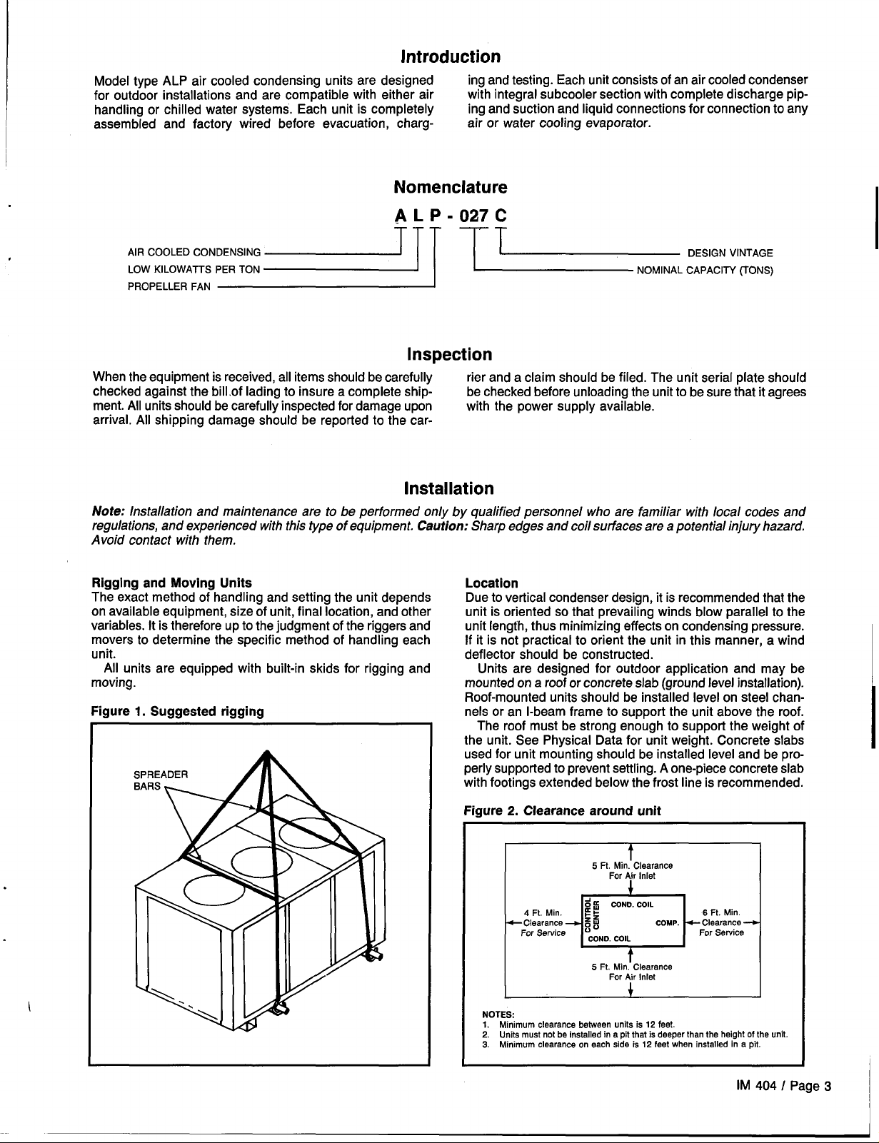
Rigging and Moving Units
The exact method of handling and setting the unit depends
on available equipment, size of unit, final location, and other
variables. It is therefore up to the judgment of the riggers and
movers to determine the specific method of handling each
unit.
All units are equipped with built-in skids for rigging and
moving.
Figure 1. Suggested rigging
Location
Due to vertical condenser design, it is recommended that the
unit is oriented so that prevailing winds blow parallel to the
unit Iength, thus minimizing effects on condensing pressure.
If it is not practical to orient the unit in this manner, a wind
deflector should be constructed.
Units are designed for outdoor application and may be
mounted on a roof or concrete slab (ground level installation).
Roof-mounted units should be installed level on steel channels or an l-beam frame to support the unit above the roof.
The roof must be strong enough to support the weight of
the unit. See Physical Data for unit weight. Concrete slabs
used for unit mounting should be installed level and be properly supported to prevent settling. A one-piece concrete slab
with footings extended below the frost line is recommended.
Figure 2. Clearance around unit
t
5 Ft. Min. Clearance
For Air Inlet
&u
COND. COIL
Min. r- =
4 Ft.
Clearance ~ g
For Service
“o”
rcp
COND. COIL
Ft. Min. Clearance
5
For Air
COMP. Clearance
Inlet
6 Ft. Min.
For Service
NOTES
1. Minimum clearance between units is 12 feet.
2. Units must not be Installed in a pit that is deeper than the height of the unit.
3. Minimum clearance on each side is 12 feet when installed in a pit.
IM 404 I Page 3
Refrigerant Piping
General
Piping design, sizing and installation information presented
in ASHRAE Handbooks should, where applicable, be followed
in the design and installation of piping. McQuay type ALP
condensing units are adaptable to either chilled water or air
handling air conditioning applications. The only restriction on
applications is that the evaporator be selected for a system
using refrigerant R-22.
Refrigerant Piping
Piping between the condensing unit and the cooling coil must
be designed and installed to minimize pressure drop, prevent liquid refrigerant carryover to the compressor and to
assure a continuous return of compressor oil from the system.
Piping sketches and tables are not intended to provide information on all of the possible arrangements.
Piping recommendations include:
1.
The use of type K or L clean copper tubing. All joints should
be thoroughly cleaned and brazed with high temperature
solder.
2.
Piping sizes should be based on temperature/pressure
limitations as recommended in the following paragraphs.
Under no circumstances should pipe size be based upon
the coil or condensing unit piping connection size.
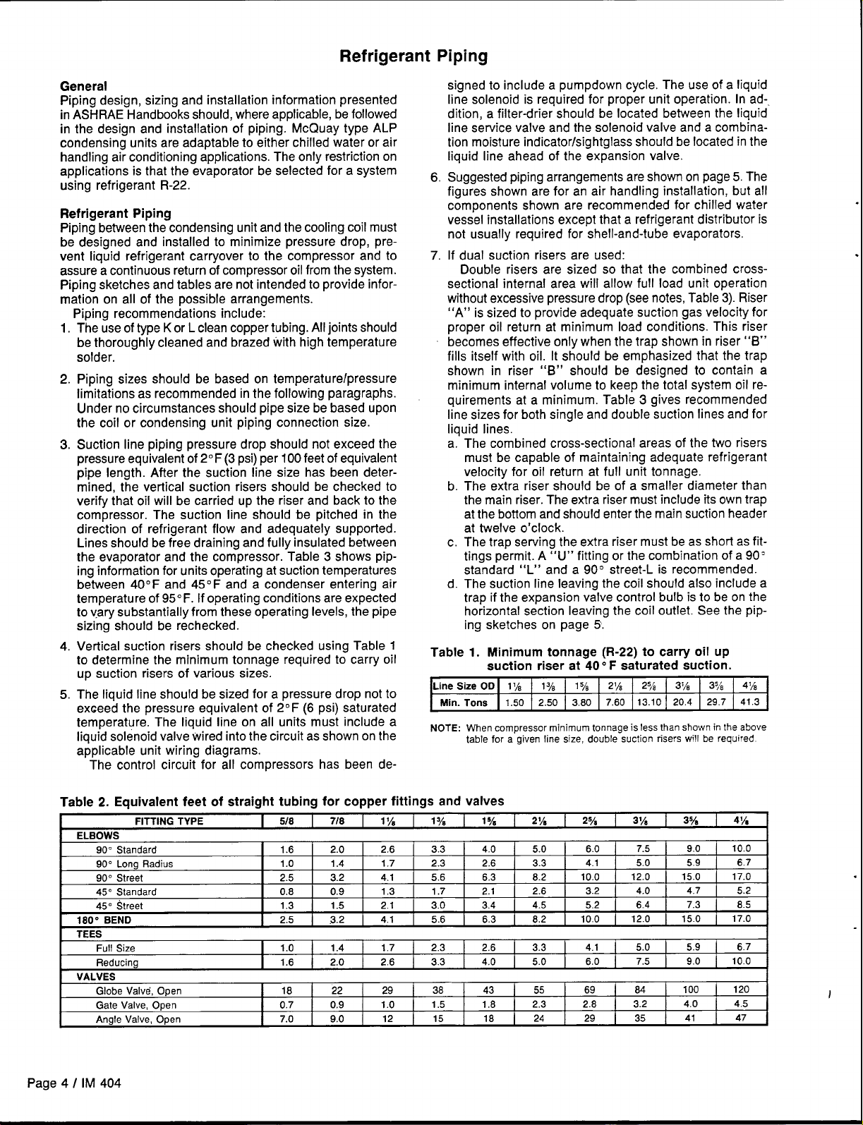
3.
Suction line piping pressure drop should not exceed the
pressure equivalent of 2° F (3 psi) per 100 feet of equivalent
pipe length. After the suction line size has been determined, the vertical suction risers should be checked to
verify that oil will be carried up the riser and back to the
compressor. The suction line should be pitched in the
direction of refrigerant flow and adequately supported.
Lines should be free draining and fully insulated between
the evaporator and the compressor. Table 3 shows piping information for units operating at suction temperatures
between 40F and 45F and a condenser entering air
temperature of 95° F. If operating conditions are expected
to vary substantially from these operating levels, the pipe
sizing should be rechecked.
4.
Vertical suction risers should be checked using Table 1
to determine the minimum tonnage required to carry oil
up suction risers of various sizes.
The Iiquid line should be sized for a pressure drop not to
5.
exceed the pressure equivalent of 2° F (6 psi) saturated
temperature. The liquid line on all units must include a
liquid solenoid valve wired into the circuit as shown on the
applicable unit wiring diagrams.
The control circuit for all compressors has been de-
signed to include a pumpdown cycle. The use of a liquid
line solenoid is required for proper unit operation. In ad-.
dition, a filter-drier should be located between the liquid
line service valve
and the solenoid valve and a combina-
tion moisture indicator/sightglass should be located in the
liquid line ahead of the expansion valve.
Suggested piping arrangements are shown on page 5. The
6
figures shown are for an air handling installation, but all
components shown are recommended for chilled water
vessel installations except that a refrigerant distributor is
not usually required for shell-and-tube evaporators.
If dual suction risers are used:
7
Double risers are sized so that the combined crosssectional internal area will allow full load unit operation
without excessive pressure drop (see notes, Table 3). Riser
“A” is sized to provide adequate suction gas velocity for
proper oil return at minimum load conditions. This riser
becomes effective only when the trap shown in riser “B”
fills itself with oil. It should be emphasized that the trap
shown in riser “B” should be designed to contain a
minimum internal volume to keep the total system oil requirements at a minimum. Table 3 gives recommended
line sizes for both single and double suction lines and for
Iiquid lines,
a.
‘ The combined cross-sectional areas of the two risers
must be capable of maintaining adequate refrigerant
velocity for oil return at full unit tonnage.
b.
The extra riser should be of a smaller diameter than
the main riser. The extra riser must include its own trap
at the bottom and should enter the main suction header
at twelve o’clock.
The trap serving the extra riser must be as short as fit-
c.
tings permit. A “U” fitting or the combination of a 90’
standard “L” and a 90° street-L is recommended.
d.
The suction line Ieaving the coil should also include a
trap if the expansion valve control bulb is to be on the
horizontal section leaving the coil outlet. See the piping sketches on page 5.
Table 1. Minimum
tonnage (R-22) to carry oil up
suction riser at 40” F saturated suction.
Line Size OD 1%
Min. Tons 1.50 2.50 3,80
NOTE: When compressor minimum tonnage is less than shown in the above
table for a given line size. double suction risers will
1
7.60 13.10 20.4
21A 2% 3~/’E 378
1 ye
3/3
4y~
29.7 41.3
be required
Table 2. Equivalent feet of straight tubing for copper fittings and valves
7/8
0,9
1%
1.7
2.1 3.0 3.4
1.7
2.6 3.3
29
1.0
12
ELBOWS
900 Standard
90° Long Radius
900 Street
45o Standard
45” Street
180° aEND
TEES
Full Size
Reducing
VALVES
Globe Valve, Open
Gate Valve, Open
Angle Valve, Open
FITTING TYPE
5/8
I
1.6 2.0 2.6 3.3
1.0 1.4
2.5 3.2 4.1 5.6 6.3
0.6 0.9 1.3 1.7 2.1
1.3 1.5
2.5 .3.2 4.1 5.6 6.3 8.2
1.0 1.4
1.6 2,0
16 22
0.7
7.0 9.0
Page 4 I IM 404
1ye 1ya 2Y8
4.0
2.3 2,6 3.3
2.3 2.6 3.3
4.0 5.0 6.0
38 43 55
1.5 1.8
15 18
5.0
8.2
2.6 3.2
4.5 5.2
2.3 2.8 3.2 4.0
24 29 35 41
25A 3~/4
6.0
4.1 5.0
10.0 12.0 15.0 17.0
10.0
4.1 5.0
69 84 100
7.5
4.0
6.4 7.3 8.5
12.0
7.5
378
I
9.0
5.9
4.7 5.2
15.0
5.9
9.0
49A
10.0
6.7
17.0
6.7
10.0
I
120
4.5
47
.
I
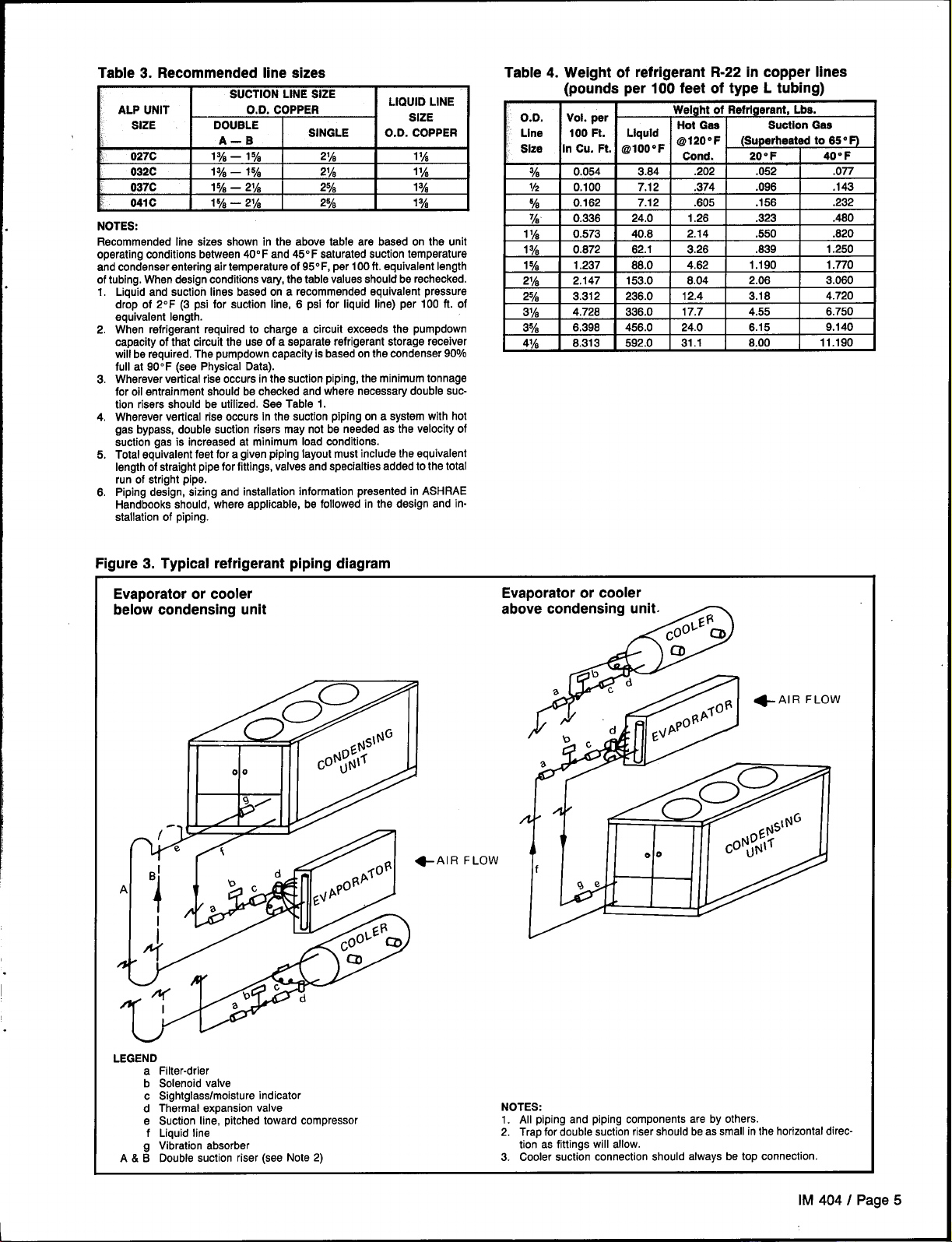
Table 3. Recommended line eizes
ALP UNIT 0.0. COPPER
SIZE
!
027C
032C
037C
041C
)
NOTES:
Recommended line sizes shown in the above table are based on the unit
operating conditions between 40° F and 45” F saturated suction temperature
and condenser entering air temperature of 95” F, per 100 ft. equivalent length
of tubing. When design conditions vary, the table values should be rechecked.
Liquid and suction lines based on a recommended equivalent pressure
1.
drop of 2F (3 psi for suction line, 6 psi for liquid line) per 100 ft. of
equivalent length.
When refrigerant required to charge a circuit exceeds the pumpdown
2.
capacity of that circuit the use of a separate refrigerant storage receiver
will be required. The pumpdown capacity is based on the condenser
full at 90iF (see Physical Data).
3.
Wherever vertical rise occurs in the suction piping, the minimum tonnage
for oil entrainment should be checked and where necessary double suction risers should be utilized. See Table 1.
4.
Wherever vertical rise occurs in the suction piping on a system with hot
gas bypass, double suction risers may not be needed as the velocity of
suction gas is increased at minimum load conditions.
5.
Total equivalent feet for a given piping layout must include the equivalent
length of straight pipe for fittings, valves and specialties added to the total
run of straight pipe.
Piping design, sizing and installation information presented in ASHRAE
6.
Handbooks should, ‘where applicable, be followed in the design and installation of piping.
DOUBLE
A–B
134 — lye 21A
1% — 1% 2% 1~~
SINGLE
lye — 21A 2%
lye — 21A 2’% 1ye
SUCTIONLINESIZE
LIQUID LINE
SIZE
O.D. COPPER
11A
l%
90%
Table 4. Weight of refrigerant R-22 in copper lines
(pounds per 100 feet of type L tubing)
0.0.
Vol.per
Line 100 Ft. Llquld
in Cu. Ft. r@lOO”F
Size
0.054 3.64
%
V2 0.100 7.12 .374
0.162 7.12 .605 .156
%
0.336
‘h
11A 0.573 40.8 2.14
Weight of Refrigerant, Lbe.
Hot Gas
@120”F (Superheated to 65” F)
Cond. 20” F 40” F
.202
24.0 1.26
.052 .077
.096
.323
.550
Suction Gas
1% 0.672 62.1 3.26 .639 1.250
1% 1.237 86.0
2% 2.147 153.0 6.04 2.06 3.060
2% 3.312 236.0
3%
3y,
4j~ 6.313 592.0 31.1 8.00 11.190
t
4.726
6.398I456.0 24.0
I
336.0
4.62
12.4
17.7
1.190 1.770
3.16
4.55 6.750
6.15
.143
.232
.460
.620
4.720
9.140
I
Figure 3. Typical refrigerant piping diagram
Evaporator or cooler
below condensing unit
AIR FLOW
Evaporator or cooler
ab
I
LEGEND
a Filter-drier
b Solenoid valve
c 8ightglass/moisture indicator
d Thermal expansion valve
e Suction line, pitched toward compressor
f Liquid line
g Vibration absorber
A & B Double suction riser (see Note 2)
NOTES:
1. All piping and piping components are by others.
2. Trap for double suction riser should be as small in the horizontal direction as fittings will allow.
3. Cooler suction connection should always be top connection.
lM 404 I Page 5
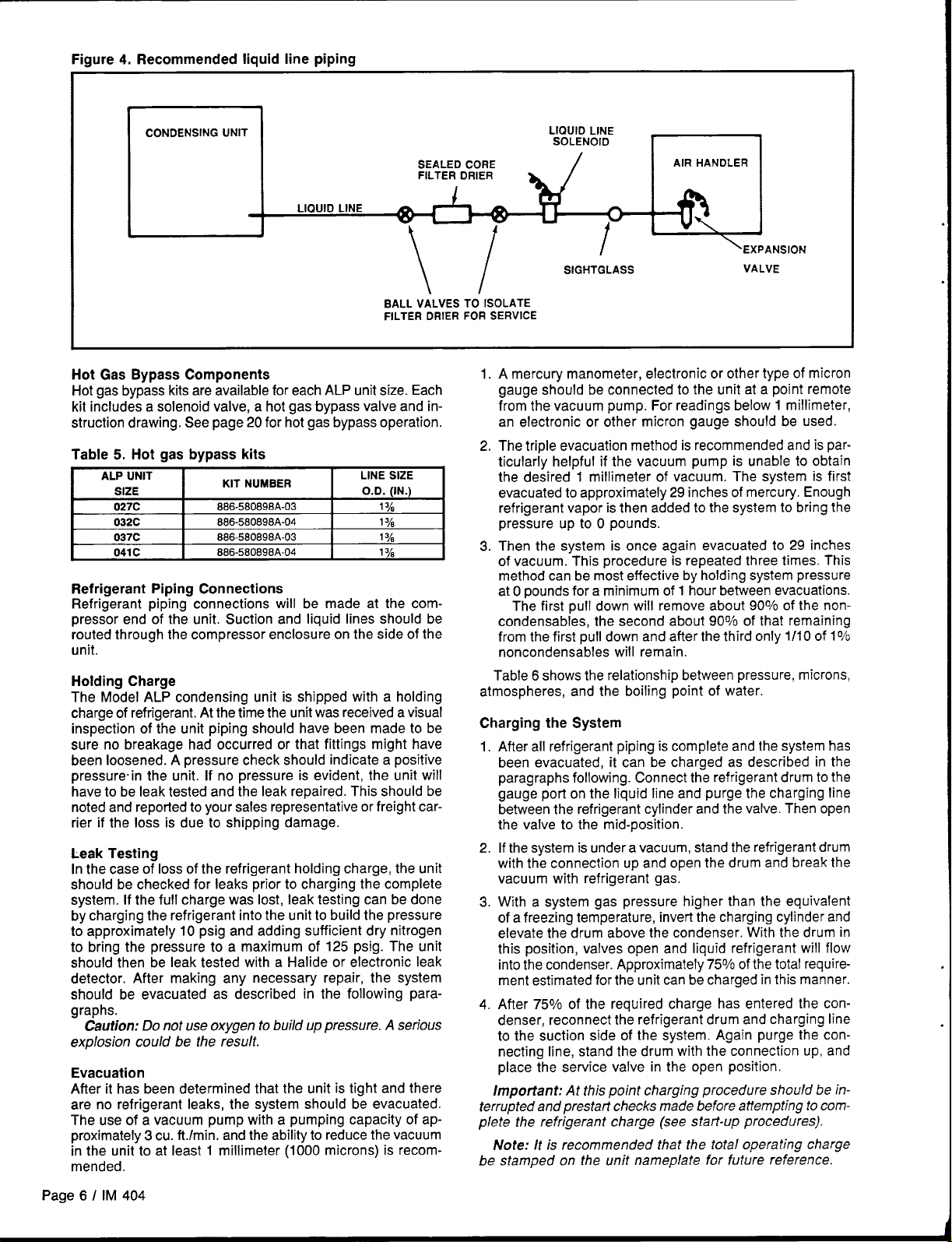
Figure 4. Recommended liquid line piping
CONDENSING UNIT
SEALED CORE
FILTER DRIER
LIQUID LINE
\/
BALL VALVES TO ISOLATE
FILTER DRIER FOR SERVICE
Hot Gas Bypass Components
Hot gas bypass kits are available for each ALP unit size. Each
kit includes a solenoid valve, a hot gas bypass valve and instruction drawing. See page 20 for hot gas bypass operation.
Table 5. Hot gas bypass kits
ALP UNIT
SIZE
027C
032C
037C
041 c 886-580898A-04
y.
KIT NUMbER
886-580898A-03 1ye
886-580898A-04 1ye
888-580898A-03 1ye
LINE SIZE
O.D. (IN.)
1ye
Refrigerant Piping Connections
Refrigerant piping connections will be made at the compressor end of the unit. Suction and liquid lines should be
routed through the compressor enclosure on the side of the
unit.
Holding Charge
The Model ALP condensing unit is shipped with a holding
charge of refrigerant. At the time the unit was received a visual
inspection of the unit piping should have been made to be
sure no breakage had occurred or that fittings might have
been loosened. A pressure check should indicate a positive
pressure in the unit. If no pressure is evident, the unit will
have to be leak tested and the leak repaired. This should be
noted and reported to your sales representative or freight carrier if the loss is due to shipping damage.
Leak Testing
In the case of loss of the refrigerant holding charge, the unit
should be checked for leaks prior to charging the complete
system. If the full charge was lost, leak testing can be done
by charging the refrigerant into the unit to build the pressure
to approximately 10 psig and adding sufficient dry nitrogen
to bring the pressure to a maximum of 125 psig. The unit
should then be leak tested with a Halide or electronic leak
detector. After making any necessary repair, the system
should be evacuated as described in the following paragraphs.
Caution: Do not use oxygen to build up pressure. A serious
explosion could be the result.
Evacuation
After it has been determined that the unit is tight and there
are no refrigerant leaks, the system should be evacuated.
The use of a vacuum pump with a pumping capacity of approximately 3 cu. ft./rein. and the ability to reduce the vacuum
in the unit to at least 1 millimeter (1000 microns) is recommended.
LIQUID LINE
SOLENOID
AIR HANDLER
u
r “n\”
SIGHTGLASS
EXPANSION
VALVE
1. A mercurv manometer, electronic or other type of micron
gauge should be connected to the unit at a-point remote
from the vacuum pump. For readings below 1 millimeter,
an electronic or other micron gauge should be used.
2. The triple evacuation method is recommended and is particularly helpful if the vacuum pump is unable to obtain
the desired 1 millimeter of vacuum. The system is first
evacuated to approximately 29 inches of mercury. Enough
refrigerant vapor is then added to the system to bring the
pressure up to O pounds.
3. Then the system is once again evacuated to 29 inches
of vacuum. This procedure is repeated three times. This
method can be most effective by holding system pressure
at Opounds for a minimum of 1 hour between evacuations.
The first pull down will remove about 90% of the noncondensables, the second about 90% of that remaining
from the first pull down and after the third only 1/10 of 1%
noncondensables will remain.
Table 6 shows the relationship between pressure, microns,
atmospheres, and the boiling point of water.
Charging the System
After all refrigerant piping is complete and the system has
1.
been evacuated, it can be charged as described in the
paragraphs following. Connect the refrigerant drum to the
gauge port on the liquid line and purge the charging line
between the refrigerant cylinder and the valve. Then open
the valve to the mid-position.
2.
If the system is under a vacuum, stand the refrigerant drum
with the connection up and open the drum and break the
vacuum with refrigerant gas.
3.
With a system gas pressure higher than the equivalent
of a freezing temperature, invert the charging cylinder and
elevate the drum above the condenser. With the drum in
this position, valves open and liquid refrigerant will flow
into the condenser. Approximately 75% of the total requirement estimated for the unit can be charged in this manner.
After 75% of the required charge has entered the con-
4.
denser, reconnect the refrigerant drum and charging line
to the suction side of the system. Again purge the connecting line, stand the drum with the connection up, and
place the service valve in the open position.
Important: At this point charging procedure should be in-
terrupted and prestart checks made before attempting to com-
plete the refrigerant charge (see start-up procedures).
Itis recommended that the total operating charge
Note:
be stamped on the with nameplate for future reference.
Page 6 I IM 404
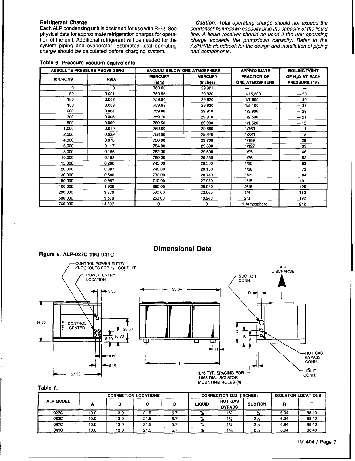
Refrigerant Charge
Each ALP condensing unit is designed for use with R-22. See
physical data for approximate refrigeration charges for operation of the unit. Additional refrigerant will be needed for the
system piping and evaporator. Estimated total operating
charge should be calculated before charging system.
Table 6. Pressure-vacuum equivalents
ABSOLUTE PRESSURE ABOVE ZERO
MICRONS PSIA
o
50 0.001 759.95
100 0.002
150 0.003 759,85
200 0.004
300 0.006 759,70
500 0.009 759.50
1,000 0.019
0
2,000 0.039
4,000 0.078
VACUUM BELOW ONE ATMOSPHERE APPROXIMATE
MERCURY MERCURY FRACTION OF
(mm)
760,00
759.90 29.920
759.80 29.910
759.00 29.880
758.00 29.840
756.00 29.760
6,000 0.117 754.00
6,000
10,000 0.193
15,000 0.290
20,000 0.387
30,000 0.580
50,000 0.967
100,000 1.930
200,000 _—..500,000
760,000 14.697
0.156
1
3.870 560.00
9.670
I
752.00 29.600
750.00 29.530
745.00
740.00 29130 1/38
730.00
710.00
660.00 25.960
260.00 10.240
0 0 1 Atmosphere
Caution: Tots/ operating charge shou/dnot exceed the
condenser pumpdown capacity plus the capacity of the liquid
Iine. A liquid receiver should be used if the unit operating
charge exceeds the pumpdown capacity. Refer to the
ASHRAE Handbook for the design and installation of piping
and components.
BOILING POINT
(Inches)
29.921
29.920 1/15,200
29.920
29.910 1/2,500
29,900
ONE ATMOSPHERE PRESSURE (’F)
.
1/7,600 — 40
1/5,100 — 33
1/3,800 — 28
1/1,520 — 12
OF H,O AT EACH
—
— 50
— 21
1/760 1
11380 15
1/189 29
29.690
I
29.330
28.740
27.950
22.050 1/4 157
1/127 39
1/95
I
1/76 52
1/50
I
1/25 64
1/15 101
2115 125
2/3 192
I
I
I
,
I
46
63
7? I
---
212
i
Figure 5.
ALP-027C thru 041 C
CONTROL POWER ENTRY
KNOCKOUTS FOR
POWER ENTRY
LOCATION
((
V,” CONOUI1
\\ -7r5”30
+ 4.60
4
57.50
1-
--F
Table 7.
I I
. , . ..---,
AI-F MW.JEL
027C 10.0 13.0 21.5
032C 10.0 13,0 21.5
037C 10.0 13.0 21.5 5.7
041C 10.0 13.0
A B
6.10
?ONNFCTION I CW!ATIC)N.Q I fY3NNFCTU3N n II llNCH~s)
c
w .. ..-.- . . . . . -= --- . . . . .
I I k ---- -... I
Dimensional Data
is-
c D LIQUID
21.5 5.7
T
1
5.7
5.7
1.75TV? SPACING FOR
DIA. ISOLATOR
1.093
MOUNTING HOLES (4)
“-------- . . . . ---- . . . . . . . .
~8
%
~8
%
nu I wm
aYPAss
11A 1 ya
11A 21A 6.94 86.40
11A
11A 21A
AIR
DISCHARGE
J
ISOLATOR LOCATIONS
SUCTION
21A 6.94 68.40
R T
6.94
6.94 8S.40
\ Ll&jlD
CONN.
88.40
IM 404 I Page 7

Vibration Isolators
Rubber-in-shear or spring isolators can be purchased from
SnyderGeneral for field installation. It is recommended that
a rubber-in-shear pad be used as the minimum isolation on
all rooftop installations or areas in which vibration transmission is a consideration. Figure 6 shows isolator locations in
relation to the unit control center. The dimensional data gives
mounting hole location dimensions.
Table 8, Recommended vibration isolators
ALP UNIT ISOLATOR McQUAYPART
SIZE
027C,032C,037C
041C
Figure 6. Isolator
mounting
locations
NPE NUMBER REQUIRED
Rubber-in-Shear
Spring-Flex
Rubber-in-Shear
Spring-Flex
216397A-01 4
477927A-26
216397A-01
216397A-03
477927A-26 2
477927A-27 2
r
When spring type isolators are required, install springs running under the main unit support per the dimensional data.
Adjust spring type mountings so that the upper housing clears
the lower housing by at least 1/4” and not more than
rubber anti-skid pad should be used under isolators if holddown bolts are not used.
NUMBER
4 All CP-1-26
2
2 2&3
LOCATION
All 8P-3 Red
l&4 RP-3 Red 525
l&4 CP-1-26
2&3 CP-I-27
ISOLATOR
DESCRIPTION
RP-3
Green
1/2”. A
MAX.LOAD
EACH (LBS.)
525
600
725
600
750
L
NOTE: See Dimensional Data for isolator mounting hole dimensions.
Figure 7. Single rubber-in-shear mounting
%“DIA.
POSITIONING
‘&
PIN
2%,,
Figure 8. Spring-flex mountings
DIA
% “
POSITIONING .
ACOUSTICAL NON-SKID
NEOPRENE PAD
AWUS? MOUNTING so UPPER I+OUSFNG
CLEAJ7SLOWER HOUSING W AT LEAST
MOe.E THAY vi “
%,” h NOT
Page 8 I IM 404

Physical Data
I
Table 9.
DATA
I
02,7C
I
BASICDATA
UNIT CAPACITY @ ARI CONDITIONS, TONS @
NO. OF REFRIGERANT CIRCUITS
UNIT OPERATING CHARGE, LBS. R-22
PUMPDOWN CAPACITY @ 90° F 60.5 60.5 60.5
CABINET DIMENSIONS, LX W
UNIT WEIGHT (LBS.)
ADD’L WT. IF COPPER FINNED COILS (LBS.) 350
COMPRESSORS – COPELAMETIC FULLY ACC
NOMINAL HORSEPOWER
NO. OF CYLINDERS PER COMPRESSOR
CYLINDER BORE (INCHES)
CYLINDER STROKE (INCHES)
COMPRESSOR OIL CHARGE
; CAPACITY REDUCTION STEPS — PERCENT OF
STANDARD STAGING 0-50-100
OPTIONAL STAGING
; CONDENSERS –
COIL FACE AREA (SQ. FT.)
FINNED HEIGHT
FINS PER INCH
j CONDENSER FANS - DIRECT DRIVE PROPELL
NO. OF FANS – FAN DIAMETER (INCHES)
NO. OF MOTORS — HORSEPOWER
FAN AND MOTOR RPM
FAN TIP SPEED (FPM)
TOTAL UNIT AIRFLOW (CFM)
NOTE: @ Nominal capacity based on 950F ambient air and 45° F saturated suction temperature.
HIGH EFFICIENCY FIN AND T
X FINNED LENGTH (INCHES) 84X 64
X ROWS DEEP
X H (INCHES)
ESSIBLE, SEMI-HERMETI
UBE TYPE WITH INTEGR
ER TYPE
26.2 29.2
1 1 1 1
15.7
X 57.5X 46 95.5 X 57.5X 46
95.5
1360
c
25 30 35
4
2.6675
2.1675 2.1675 2.1675
136 152 160 242
COMPRESSOR DISPLA
NA NA
49.0
14x2
3—26 3—26 3–26
3— 1.0
1100
7760
21,525
CEMENT
AL SUBCOOLER
ALP MODELNUMBER
032C 037C
15.7
95.5
1450
340
4
2.9375
0-50-100
0-33-67-100
49.0 49.0 49.0
84X 64
16x2 16x2 14X3
3— 1.0
1100
7760 7760 7760
20,925 20,925
36.6
15.7
X 57.5X 46
1460
340 530
6 6
2.6675
0-67-100
84X 84
3— 1.0
1100
95.5
041c
41.6
21.7
87.6
X 57.5X 46
1600
40
2.9375
2.1875
0-67-100
0-33-67-100
64X 64
3—26
3— 1.0
1100
20,025
I
I
IM 404 I Page 9

Electrical Data
Table 10. Wire sizing ampacities & recommended power lead wire sizes.
CAUTION: Electrical data for single point power wiring. A single fused disconnect to supply electrical power to the unit is required.
3 PHASE, 60 HZ
ALP UNIT
027C
032C
037C
041C
wire si.zfna amDs are eaual ta 1250/o af the RLA af the laraest mater Dlus
100VO
of t;e Rb of all other loads in the circuit. Wre sizi;g amps sh~wn
are for units with all loads on a common supply circuit, including control
transformer.
If the unit includes a factory wired control circuit transformer, no separate
115V pawer is required. If a separate 115V supply is used far the control
circuit, the wire sizing amps is 2 amps.
Recommended pawer lead wire sizes for three conductors per conduit are
based on 1000/o canductor ampacity and no more than 3 conductors per
conduit.
ELECTRICAL
POWER SUPPLY
@
208
230
460 55 6
575
208
230
460 73
575 52
208
230 153
460 77
575
208 204
230
480 95
575
WIRE SIZING LEAD WIRE SIZES (3
AMPS 0 3 WIRES
109 2
109 2
46 6
145
145 1/0
153 2/0
63
188 3/0
75
RECOMMENDED COPPER POWER
HUB FUSE SIZE B
1 CONDUIT DIAMETER
1.50
1.50
1.00
1.00 50
1/0 2.00
4
6
2/0 2.00
4
6
4/0 2.50
3
4 1.25 90
Voltaae drap has nat been included. Therefore, it is recommended that
power I;ads be kept short. All terminal block connections must be made
with copper
The unit power termina! block may have two lugs per phase. Single or
O
parallel conductors should be used for power connection as listed under
“Recommended Power Lead Wre Size.”
@ “Recommended Fuse Sizes” are selected appraxima!ely 150Yc of the
largest motor RLA, plus 1000/o of
@ Electrical data for 380/50/3 is the same as 460/60/3
@ See page 10 for voltage limitations
(Type TH~ wire.
2,00
1.25 80
1.25 60
2.00
1.25 90
1.25 80
2.50
1.25
all other laads in the circuit
RECOMMENDED
125
125
60
175
175
175
175
225
200
100
Table 11. Compressor and condenser fan motor amDs draw
PH, 50 HZ
3
ALP UNIT
027C
032C
037C
041C
NOTES:
@ See electrical data sheet for voltage limits.
@ If the unit is equipped with a speed controlled motor, the first motor is a 230V, single phase, 1.0 horsepower motor, with an RLA of 5.6 amps
Compressor RLA amps far part winding are for the first winding anly. If the unit is equipped with a
phas’e, 1.0 horsepower moior, with an-LRA af 14.5 amps
Electrical data for 380/50/3 is the same as 460/60/3.
ELECTRICAL
POWER
SUPPLY @
206 77
230 77
460 39
575
208 106
230
460 53 2.0
575 56
208 112
230
460 56
575
208
230 140
460 71 2.0
RATED LOAD AMPS C2
COMPRESSOR
41 2.2
106 4,0
112 4.0
45
153 4.0 3
FAN MOTORS
(EACH)
4.0 3
4.0 3
2.0
4.0 3
2.2 3
4.0 3
2.0
2.2 3
4.0 3
NO. OF
FAN MOTORS FAN MOTORS
3 9.9
3
3 17.0
3 9.9
3 17.0 565
3 9.9
3 9.9
COMPRESSOR LOCKED ROTOR AMPS 2
(EACH)
17.0 428
17.0 428
10.3 172
17,0
10.3
17.0 565
10.3 230
17,0 660
17.0 594 340
speed controlled motor, the first motor is a 230V. single
AL START
214
470
470
235
217
283
297
PW START
Voltage Limitations
Unit Nameplate = 208V/60Hz/3Ph = 187V to 253V
Unit Nameplate = 230V/60Hz/3Ph = 187V to 253V
Unit Nameplate = 460V/60Hz/3Ph = 414V to 506V
Unit Nameplate =575V160Hz/3Ph=517V to 633V
Unit Nameplate = 380V/50Hz/3Ph = 342V to 418V
250
250
117
103
292
292
141
130
340
340
156
l?X
400
170
Page 10 I IM 404

Field Wiring
Warning: Use only copper conductors in main terminal block.
Figure
Wiring should
and ordinances. Warranty is voided if wiring in not in accor-
i
dance with specifications. An open fuse indicates a short,
ground or overload. Before replacing a fuse or restarting a
be done in accordance with all applicable codes
installation. Items that require field wiring are liquid line
solenoid SV1, optional hot gas bypass solenoid SV5 and the
cooling thermostat, as well as the unit power supplies.
compressor or fan motor, the. trouble must be found and
corrected.
9 shows typical field wiring that is required for unit
NOTE: See dimensional data for knockout locations.
Figure 9. Typical field diagram/2 stage —
DISCONNECT
BY OTHERS
–“””–~
3 PHASE
POWER
SUPPLY
--+--i-l-
—--i——
BK
I
SEPARATE 115V POWER
!
FOR CONTROLS.
DISCONNECT BY OTHERS
\
(SEE NOTE 0)
1
1
+--
FUSE (Fl)
4
J-% -~1
CONTROL STOP
SWITCH(ES)
——
NOTE: REMOVE WIRES 509 & 510
TO INSTALL TIME CLOCK &
FAN INTERLOCK.
ALP-027C thru 041 c
PB1
UNIT MAIN
TERMINAL BLOCK
—-
120 VOLT MAIN
UNIT CONTROLS
I
OPTIONAL FUSED
CONTROL TRANSFORMER
I
CONOENSER UNIT
COMPRESSOR AND
FAN MOTORS
WH
I
1
509
5io
L:;% 1~ ~&R=-u-N~
STAGE 1
sTAGE 2 & ~_@
STAGE 3 & *C ~
I
ON ALP.037C THRU 041C UNITS ONLY
I
NOTE 0: Standard is separate power supply circuits for controls
TERMINALS FOR
114
114 118
116
LEGEND
@
——.
117
HOT GAS BYPASS
1
217
FIELD WIRING TERMINAL —--— OPTIONAL FACTORY WIRING
FIELD WIRING
FACTORY WIRING
BK BLACK WIRING (LINE)
WH
m
WHITE WIRING (NEUTRAL)
I
I
1
I
●
IM 404 / Page 11

Figure 10. Control center layout — ALP-027C thru 041 C
Figure 11. Recommended unit disconnect location
DESIGNATION
c11
COMPR 1
0s1
F1
FS5
FB6, FB7
GRD
HP1
HTR 1
LPI
MI–5
M71—13
MJ
MP1
MTR1l—13
NE
OP1
PB1
PC5
PC12
—HIGH SIDE PRESSURE PORTS
m
DESCRIPTION
CAPACITORS FOR FAN MOTORS
COMPRESSOR
DISCONNECT SWITCH, MAIN
FuSE, CONTROL CIRUCUIT
FUSEBLOCK, CONTROL POWER
FUSEBLOCKS. FAN MOTORS
GROUND
HIGH PRESSURE CONTROL
HEATER, COMPRESSOR CRANKCASE
LOW PRESSURE CONTROL
CONTRACTORS, COMPRESSOR
MOTORS CONDENSER FANS
MECHANICAL JUMPERS
MOTOR PROTECTOR, COMPRESSOR
MOTORS, CONDENSER FANS
NEUTRAL BLOCK
OIL PRESSURE CONTROL
POWER BLOCK MAIN
PRESSURE CONTROL, HI AMBIENT
UNLOAOER
PRESSURE CONTROL, FANTROL
H
Electrical Legend
STD. LOCATION
BACK OF CONTROL BOX
BASE OF UNIT
FIELD SUPPLIED
CONTROL BOX
CONTROL BOX
CONTROL BOX
CONTROL BOX
ON COMPRESSOR
ON COMPRESSOR
ON COMPRESSOR
CONTROL BOX
CONTROL SOX
CONTROL SOX
COMPRESSOR JUNCTION BOX
CONDENSER SECTION
CONTROL BOX
CONTROL BOX
CONTROL BOX
CONTROL BOX
CONTROL BOX
:1
Sc
11
Control Power Entry
Knockouts For V2” Conduit
DESIGNATION DESCRIPTION
I
Ps1
PVM
R5
R9
R13
R21
S1
SC1l
Svl
SV5
T1
T3
TB2
TS3
T&! TB5
TC13
TO 1
TD5
T09
U1, U2
Power Entry Location
0 CONTROL
n CENTER
PUMPDOWN SWITCH
PHASE VOLTAGE MON!TOR
RELAY, SAFETY
RELAY, STARTING
nELAY, LOW AMBIENT START
RELAY, HI AMBIENT UNLOAOER
SWITCH, CONTROL STOP
SPEED CONTROL
SOLENOIO VALVE. LIQUID LINE
SOLENOID VALVE HOT GAS BYPASS
TRANSFORMER MAIN CONTROL
TRANSFORMER, FAN SPEEDTROL
TERMINAL BLOCK, 120V, FIELO
TERMINAL BLOCK, 24V, FIELO
TERMINAL BLOCKS, CONTROL
THERMOSTAT, FANTROL
TIME OELAY, COMPRESSOR LOCKOUT
TIME OELAY. COMPRESSOR PART WNDING
TIME OELAY. LOW AMBIENT
UNLOADERS
Field Mounted
Disconnect
To Be Mounted
In This Area
STD. LOCATION
COVROL BOX
COWROL BOX
CONTROL BOX
CONTROL BOX
CONTROL BOX
CONTROL BOX
CONTROL SOX
TOP OF CQhTFOL EOX
FIELD INSTALLED
FIELO lNS~ALLEG
CONT=OL BOX
SACK OF CON-OL ECX
CONTRCL !30X
CONTROL BOX
CO~OL SOX
~NTRCL 80X
CONTROL BOX
CQNTROL BOX
CONTROL BOX
ON COU=SESSORS
All wiring must be done in accordance with applicable local
and national codes.
A single large
within the unit is
trical Code. A single field supplied disconnect is required. An
power terminal block is provided and wiring
sized in accordance with the National Elec-
optional factory mounted transformer may be provided.
Main Power Disconnect Switch
Disconnecting means are addressed by Article 440 of the National Electrical Code (NEC) which requires “disconnecting
means capable of disconnecting air conditioning and refrigerating equipment including motor-compressors, and controllers from the circuit feeder.” The disconnect switch should
be selected and located within the NEC guidelines. Location
requirements per NEC are that the disconnect be located in
a readily accessible position within sight (50 ft.) of the unit.
Maximum recommended fuse sizes are given in the Electrical
Data table on page 10 of this manual for help in sizing the
e
disconnect.
Page 12 I IM 404
Electrical Hook-up
ALP units have a single factory installed main power supply
connection point which requires one main power supply
disconnect switch, supplied by others. For recommended copper power lead wire sizes see the Electrical Data table on page
10 of this manual.
Control Circuit
Terminals are provided
1 and NB1, Typical Field Wring Diagram) for field hook-up
of the control circuit to a 115V power supply. An optional “Control Circuit Transformer” is available, factory installed. to
eliminate the requirement for a separate power supply to the
control circuit.
Terminals are also provided for field connection of the fan
interlock or chilled water flow switch (chilled water systems
only), liquid line solenoid valve, system time clock, ambient
thermostat, and/or remote on-off switch and temperature control thermostat.
in the unit control center (terminals

Normal Sequence of Operation
The following sequence of operation is typical for ALP-027C
through 041C SeasonCon air cooled condensing units.
Start-up
With the control circuit power on and the control stop switch
S1 closed, 115V power is applied through the control circuit
fuse F1 to the compressor crankcase heater HTR1, the com-
pressor motor protector MP1, and the contacts of the low and
high pressure switches LPI and HP1.
When the remote time clock(s) or manual shutdown
switch(es) turn on the evaporator fan(s) or chilled water pump,
115V power is applied to the temperature or pressure control. The unit will automatically operate in response to the
temperature or pressure controller provided (1) the manual
pumpdown switch PS1 is closed (in the “auto” position); (2)
the compressor lockout time delay TD1 has closed, energizing
safety relay R5; and (3) the high pressure control HP1 and
compressor motor protector MP1 do not sense failure conditions.
On a call for cooling, the temperature or pressure control
thermostat energizes the liquid line solenoid valve SW, opening the valve and allowing refrigerant to flow through the expansion valve and into the evaporator. As the evaporator
refrigerant pressure increases, the low pressure control LP1
closes. This energizes the compressor starting relay R9, start-
ing the compressor via the compressor contactor Ml. Closing R9 contacts also energizes the condenser fan motor con-
tractors Mll, M12 and M13, starting the fan motors.
As additional stages of the cooling capacity are required,
the temperature or pressure control will de-energize the
unloader solenoids of the compressor, respectively.
Pumpdown Cycle
As the temperature or pressure control is satisfied, it will
unload the compressor and then de-energize the liquid line
solenoid valve SV1, causing the valve to close. When the compressor has pumped most of the refrigerant out of the
evaporator and into the condenser, the low pressure control
LP1 will open, shutting down the compressor and the condenser fan motors. In the event a closed solenoid valve allows
refrigerant to leak into the evaporator, the increase in pressure
will cause the low pressure control to close. This will energize
the compressor starting relay, start the compressor and quick-
ly pump the refrigerant out of the evaporator and into the condenser (recycling pumpdown).
Do not shut unit down without going through the pumpdown
cycle. Flow switch or fan interlock, time clock and ambient
lockout thermostat must be wired to allow pumpdown when
unit is turned off.
Start-up and
Start-up
Pre
With all electric disconnects open, check all screw or lug
1.
type electrical connections to be sure they are tight for
good electrical contact. Check all compressor valve connections for tightness to avoid refrigerant loss at startup. Although all factory connections are tight before shipment, some loosening may have resulted from shipping
vibration.
2.
On chilled water installations, check to see that all water
piping is properly connected.
Check the compressor oil level. Prior to start-up, the oil
3.
level should cover at least one-third of the oil sightglass.
Check the voltage of the unit power supply and see that
4.
it is within the + 10% tolerance that is allowed. Phase
voltage unbalance must be within + 2%.
Check the unit power supply wiring for adequate ampaci-
5.
ty and a minimum insulation temperature rating of 75C.
Verify that all mechanical and electrical inspections have
6.
been completed per local codes.
See that all auxiliary control equipment is operative and
7.
that an adequate cooling load is available for initial
start-up.
Open the compressor suction and discharge shutoff
8.
valves until backseated, Always replace valve seal caps.
Making sure control stop switch S1 is open (off) and
9.
pumpdown switch PSI is on “manual pumpdowm” throw
the main power and control disconnect switches to “on.”
This will energize crankcase heater. Wait a minimum of
12 hours before starting up unit.
If a chilled water system, open all water flow valves and
10,
start the chilled water pump. Check all piping for leaks
and vent the air from the evaporator as well as from the
system piping to obtain clean, noncorrosive water in the
evaporator circuit.
Shutdown
Caution: Most relays and terminals in the unit control center
are hot with S1 and the control circuit disconnect on. Do not
close S1 until start-up.
Initial Start-up
Double check that the compressor suction and discharge
1.
shutoff valves are backseated. Always replace valve seal
caps.
2.
Open the field supplied manual liquid line shutoff valve
at the outlet of the condenser.
Adjust the dial on temperature controller to the desired
3.
chilled water temperature or air temperature.
Start the auxiliary equipment for the installation.
4.
Check to see that pumpdown switch PS1 is in the
5.
“manual pumpdown” (open) position. Throw the emergency stop switch S1 to the “on” position. If pressures
on the low side of the system are above 60 psig, the unit
will start and pump down.
After the compressor lockout timer TD1 has timed out,
6.
start the system by moving pumpdown switch PSI to the
“auto pumpdown” position.
After running the unit for a short time, check the oil level
7.
in the compressor crankcase, rotation of condenser fans,
and check for flashing in the refrigerant sightglass (see
“System Maintenance;’ page 14).
8.
Superheat should be adjusted to maintain between 8 and
12F.
After system performance has stabilized, it is necessary
9.
that the “Compressorized Equipment Warranty Form”
(Form No. 415415Y) be completed to obtain full warranty
benefits. This form is shipped with the unit, and after completion should be returned to McQuayService through
your sales representative.
IM 404 / Page 13

Temporary Shutdown
Move pumpdown switch PSI to the “manual pumpdown”
position. After the compressor has pumped
down,turn off the “Initial Start-up” steps.)
chilled water pump or-evaporator fan. It is especially important on chilled water installations that the compressor pumpdown occurs before the water flow to the evaporator is interrupted to avoid freeze-up.
Nofe With the unit left in this condition, it is capable of
recycling pumpdown operation. Todefeat this mode of operation, move control stop switch S1 to the “off’ position.
Start-up After Temporary Shutdown
1. Start the chilled water pump or evaporator fan.
2. With emergency stop switch S1 in the “on” position, move
pumpdown switch PSI to the “auto pumpdown” position.
3. Observe the unit operation for a short time to be sure
that the compressor does not cut out on low oil pressure.
Extended Shutdown
(For start-up after extended shutdown, refer to applicable
1.
Close the field supplied manual liquid line shutoff valve.
2.
After the compressor has pumped down, turn off the
chilled water pump or evaporator fan.
Turn off
3.
ment.
Move the control stop switch S1 to the “off” position.
4.
Close the compressor suction and discharge valves,
5.
Tag all opened disconnect
6.
all power to the unit and to the auxiliary equip-
switches to warn against startup before opening the compressor suction and discharge
valves.
System Maintenance
General
On initial start-up and periodically during operation, it will be
necessary to perform certain routine
these are checking the compressor oil level and taking condensing, suction and oil pressure readings. During operation,
the oil level should be visible in the oil sightglass with the compressor running. On units ordered with gauges, condensing, suction and oil pressures can be read from the vertical
supports on each side of the unit adjacent to the compressor.
The gauges are factory installed with a manual shutoff valve
on each gauge
line. The valves should be closed at all times
except when gauge readings are being taken. On units
ordered without gauges, Shrader fittings should be installed
in the plugged ports provided on the suction and discharge
King valves.
Fan Shaft Bearings
The fan shaft bearings are of the permanently lubricated type.
No lubrication is required.
Electrical Terminals
Caution: Electric shock hazard. Turn off allpower before continuing with following service.
All power electrical terminals should be retightened every
six months, as they tend to loosen in service due to normal
heating and cooling of the wire.
Compressor Oil Level
Because of the large refrigerant charge required in an air cooled condensing unit, it is usually necessary to put additional
oil into the system. The oil level should be watched carefully
upon initial start-up and for sometime thereafter.
At the present time, Suniso No. 3GS, Calumet R015, and
Texaco WF32 oils are approved by Copeland for use in these
compressors. The oil level should be maintained at about onethird of the sightglass on the compressor body.
Oil may be added to the Copeland compressor through the
oil fill hole in the crankcase. To add oil, isolate the crankcase
and pour or pump in the necessary oil. If the system contains
service checks. Among
no refrigerant, no special precautions are necessary other
than keeping the oil clean and dry.
If the system contains a refrigerant charge, close the suction valve and reduce crankcase pressure to 1 to 2 psig. Stop
the compressor and close the discharge valve.
Add the required amount of oil. During the period the compressor is exposed to the atmosphere, the refrigerant will
generate a vapor pressure, retarding the entrance of contaminants. Before resealing the compressor, purge the
crankcase by opening the suction valve slightly for 1 or 2
seconds. Close the oil port, open the compressor valves and
restore the system to operation.
Condensers
Condensers are air cooled and constructed with 3/8]’O.D. internally finned copper tubes bonded in a staggered pattern
into slit aluminum fins. No maintenance is ordinarily required
except the occasional removal of dirt and debris from the outside surface of the fins. SnyderGeneral recommends the use
of foaming coil cleaners available at air conditioning supply
outlets. Use caution when applying such cleaners as they may
contain potentially harmful chemicals. Care should be taken
not to damage the fins during cleaning. Periodic use of the
field supplied purge valve on the condenser will prevent the
build-up of noncondensables.
Refrigerant Sightglass
The refrigerant sightglass should be observed periodically.
(A monthly observation should be adequate.) A clear glass
of liquid indicates that there is adequate refrigerant charge
in the system to insure proper feed through the expansion
valve. Bubbling refrigerant in the sightglass indicates that the
system is short of refrigerant charge. Refrigerant gas flashing
in the sightglass could also indicate an excessive pressure
drop in the line, possibly due to a clogged filter drier or
a restriction elsewhere in the system. If the sightglass does
not indicate a dry condition after about 12 hours of operation,
the unit should be pumped down and the filter driers changed.
Page 14 / IM 404

Service
Note: Service on this equipment is to be performed by qualified refrigeration service personnel. Causes for repeated tripping
of safety controls must be investigated and corrected. Caution: Disconnect all power before doing any service inside the unit.
Filter Driers
To change the filter drier, pump the unit down by moving
pumpdown switch PSI to the “manual pumpdown” position.
Move the control switch S1 to the “off” position. Turn off all
power to the unit and install a jumper across terminals 42 and
44. This will jump out the low pressure control. Close the field
supplied manual liquid line shutoff valve. Turn power to the unit
back on and restart the unit by moving the control switch S1 to
the “on” position. The unit will start pumping down past the
low pressure setting. When the evaporator pressure reaches
O-5 psig, move control switch S1 to the “off” position.
Front seat the suction line King valve. Remove and replace
the filter drier. Evacuate the line through the liquid line manual
shutoff valve to remove noncondensables that may have en-
tered during filter replacement. A leak check is recommended
before returning the unit to operation.
Liquid Line Solenoid Valve
The liquid line solenoid valve, which is responsible for auto-
matic pumpdown during normal unit operation, do not normally require any maintenance. They may, however, require
replacement of the solenoid coil or of the entire valve
assembly.
The solenoid coil may be removed from the valve body with
out opening the refrigerant piping by moving pumpdown
switch PS1l to the “manual pumpdown” position. The coil can
then be removed from the valve body by simply removing a
nut or snap-ring located at the top of the coil. The coil can
then be slipped off its mounting stud for replacement. Be sure
to replace the coil on its mounting stud before returning pumpdown switch PS1 to the “auto pumpdown” position.
To replace the entire solenoid valve follow the steps in-
volved when changing a filter drier.
ponding to the evaporator pressure.) Typically, superheat
should run in the range of 10° F to 15° F.On valves purchased
through SnyderGeneral, the superheat setting can be adjusted by removing the cap at the bottom of the valve to ex-
pose the adjustment screw. Turn the screw clockwise (when
viewed from the adjustment screw end) to increase the super-
heat setting and counterclockwise to reduce superheat. Allow
time for system rebalance after each superheat adjustment.
The expansion valve, like the solenoid valve, should not normally require replacement, but if it does, the unit must be
pumped down by following the steps involved when changing a filter drier.
If the problem can be traced to the power element only,
it can be unscrewed from the valve body without removing
the valve, but only after pumping the unit down.
Expansion valve
\
,.
‘ = Power
!l!7T
.-
Element
(Contains
Diaphragm)
Outlet
Inlet
a
I-H
,/
.
Thermostatic Expansion Valve
The expansion valve is responsible for allowing the proper
amount of refrigerant to enter the evaporator regardless of
cooling load. It does this by maintaining a constant superheat.
(Superheat is the difference between refrigerant temperature
as it leaves the evaporator and the saturation temperature cor-
In-Warranty Return Material Procedure
Compressor
Copeland Refrigeration Corporation has stocking wholesalers
who maintain a stock of replacement compressors and service parts to serve refrigeration contractors and service
personnel.
When a compressor fails in warranty, contact your local
sales representative, or our Warranty Claims Deparment at
the address on the back cover of this bulletin. You will be
authorized to exchange the defective compressor at a
Copeland wholesaler, or an advance replacement can be obtained. A credit is issued you by the wholesaler for the returned compressor after Copeland factory inspection of the
inoperative compressor. If that compressor is out of CopeIand’s warranty, a salvage credit only is allowed. Provide
full details; i.e., McQuay unit model and unit serial numbers.
Include the invoice and the salvage value credit memo copies
and we will reimburse the difference. In this transaction, be
certain that the compressor is definitely defective. If a compressor is received from the field that tests satisfactorily, a
service charge plus a transportation charge will be charged
against its original credit value.
On all out-of-warranty compressor failures, Copeland offers
the same field facilities for service and/or replacement as
described above. The credit issued by Copeland on the returned compressor will be determined by the repair charge
established for that particular unit.
Components Other Than Compressors
Material may not be returned except by permission of authorized factory service personnel of SnyderGeneral at Minneapolis,
Minnesota. A “return goods” tag will be sent to be included
with the returned material. Enter the information as called for
on the tag in order to expedite handling at our factories and
prompt issuance of credits.
The return of the part does not constitute an order for
replacement. Therefore, a purchase order must be entered
through your nearest McQuay representative. The order
should include part name, part number, model number and
serial number of the unit involved.
Following our personal inspection of the returned part, and
if it is determined that the failure is due to faulty material or
workmanship, and in warranty, credit will be issued on
customer’s purchase order.
All parts shall be returned to the pre-designated factory
transportation charges prepaid.
IM 4041 Page 15

Appendix: Standard Controls
Note: Perform an operational check on all unit safety controls one per year
High Pressure Control
The high pressure control is a single pole pressure activated
switch that opens on a rise in pressure. When the switch
opens, it de-energizes the compressor circuit, preventing unit
operation until the high pressure control resets itself. The control is factory set to open at 385 psig and reset at 285 psig.
The control is attached to a Shrader fitting on the hot gas stub
located in the compressor compartment.
To check the control, either block off the condenser sur-
face or start the unit with condenser fan motors off and
observe the cut-out point of the control on the high side of
the system.
Caution: Although there is an additional pressure relief
device in the system set at 450 psig, it is highly recommended that the unit disconnect be close at hand in case the high
pressure control should malfunction. After testing the high
pressure control, check the pressure relief device for leaks.
Low Pressure Control
The low pressure control is a single pole pressure switch that
closes on a pressure rise. It senses evaporator pressure and
is factory set to close at 60 psig and automatically open at
35 psig. To check the control (unit must be running), move
the pumpdown switch PSI to the “manual pumpdown” position. As the compressor pumps down, condenser pressure
will rise and evaporator pressure will drop. The lowest
evaporator pressure reached before cutout is the cutout setting of the control. Wait for the compressor lockout time delay
TD1 to time out. By moving the pumpdown switch PSI to the
“auto pumpdown” position, evaporator pressure will rise. The
highest evaporator pressure reached before compressor
restart is the cut-in setting of the control;
The control is attached to a Shrader fitting and is located
below the suction King valve body.
Compressor Motor Protector
The solid-state compressor motor protector module incor-
porates a two-minute “time off” relay utilizing the bleed down
capacitor principle. Any time the protection system opens or
power to the module is interrupted, the two-minute “time off’
delay is triggered, and the module will not reset for two
minutes. Once the two-minute period is passed, the motor
protector contacts 1 and 2 reset, provided the protection
system is satisfied and power is applied to the module,
Note: If the power circuit is broken once the two-minute
period is passed the pilot circuit will reset without delay when
power is reapplied.
115V Llna
115V Line
-———.
t-l
I
1
1
Mm
i
I
●
L3 ‘J——-—-
al
11
1~
I
I
●
COntml
Relay
Neutral
Ueutml
FanTrol Head Pressure Control
FanTrol is a method of head pressure control which automatically cycles the condenser fan motors in response to ambient
air temperature and actual condenser pressure. This maintains head pressure and allows the unit to continue to run
at low ambient air temperatures.
All ALP units have FanTrol which cycles fan motor 12 in
response to condenser pressure, factory set to open at 170
psig and close at 290 psig. Condenser fan motor 13 is cycled
in response to ambient air temperature and is factory set to
cut out at 70° F and cut in at 80F. Both controls are located
in the unit control box.
Table 12. Minimum ambient temperature
Compressor Lockout
Compressor lockout consists of a nonadjustable, 5-minute
time delay. It is wired in series with the R5 relay that energizes
rapid compressor cycling when cooling demands are erratic.
When the unit thermostat no longer calls for cooling and
the compressor contractor have opened, the lockout time
delay breaks open the circuit, preventing compressor restart.
The circuit remains open for a period of 5 minutes so that,
if the unit thermostat should call for cooling before the delay
period has expired, the compressor will not restart. After 5
minutes the time delay will close its contacts to complete the
circuit to R5, energizing R9 and starting the compressor. When
R9 is energized, another set of contacts will shunt around TDI,
allowing TD1 to reset open for timing out the next compressor
cycle.
To check the control, the compressor must be running initially. Move the pumpdown switch PSI to the “manual pumpdown” position. Immediately after the compressor has
stopped running, move the pumpdown switch back to the
“auto pumpdown” position. The compressor should not restart
for 5 minutes.
Line
Line
T
R5
II
TD1
R9
Neutral
Neutral
‘ine““%D---
t 041C I 10 I 40 I
0 Wth hot gas bypass only.
“Table values do not take into account the effect wind conditions w!! I have on
minmum ambient operation. A wind deflector (by others) may be necessa~
to obtain minimum ambient operation.
Oil Pressure Safety Control
The oil pressure safety control is a manually resettable device
which senses the differential between oil pressure at the
discharge of the compressor oil pump and suction pressure
inside the compressor crankcase. When
reaches approximately 15 psi above the crankcase suction
pressure, the pressure actuated contact of the control opens
from its normally closed position. If this pressure differential
cannot be developed, the contact will remain closed and
energize a heater element within the control. The heater element warms a normally closed bimetallic contact and causes
the contact to open, de-energizing a safety relay and break-
ing power to the compressor.
It takes about 120 seconds to warm the heater element
enough to open the bimetallic contact, thus allowing time for
the pressure differential to develop.
If during operation, the differential drops below 10 psi, the
heater element will be energized and the compressor will stop,
The control can be reset by pushing the reset button on the
control. If the compressor does not restart, allow a few minutes
for the heater element and bimetallic contacts to cool and reset
the control again.
check the control, pump down and shut off all power
To
the oil pressure
‘age 16 I IM 404
P

to the unit. Open the circuit breakers or the fused disconnect
for that compressor and install a voltmeter between terminals
Land M of the oil pressure control. Turn on power to the unit
control circuit (separate disconnect or main unit disconnect
depending on the type of installation). Check to see that the
control stop switch S1 is in the “on” position. The control circuit should now be energized, but with the absence of compressor power, no oil pressure differential can develop and
Appendix: Optional Controls
Note: Perform an operational check on all unit safety controls once per year
thus the pressure actuated contacts of the control will energize
the heater element and open the bimetallic contacts of the
control within 120 seconds. When this happens, the safety
relay is de-energized, the voltmeter reading will rise to 115V,
and the compressor contactor should open. Repeated opera-
tions of the control will cause a slight heat build-up in the
bimetallic contacts resulting in a slightly longer time for reset
with each successive operation.
SpeedTrol Head Pressure Control (Optional)
The SpeedTrol system of head pressure control operates in
conjunction with FanTrol by modulating the motor speed on
fan 11 in response to condensing pressure. By reducing the
speed of the last fan as the condensing pressure falls, the
unit can operate at lower ambient temperatures.
The SpeedTrol fan motor is a single phase, 208/230 volt,
thermally protected motor specially designed for variable
speed application. The solid-state speed control SC11 is
mounted inside the control panel and is connected to a
Shrader fitting on the top of the control panel. Units with 460
volt power have a transformer mounted on the back of the
control box to step the voltage down to 230 volts for the SpeedTrot motors.
The SpeedTrol control starts to modulate the motor speed
at approximately 230 psig and maintains a minimum condensing pressure of 170 to 180 psig.
Note: Minimum starting voltage for Speed7701 motors is
120V
Low Ambient Start (Optional)
Low ambient start is available on all units as an option with
)
FanTrol and included automatically with optional SpeedTrol.
It consists of a solid-state, normally closed time delay wired
in series with a relay. These are both wired in parallel to the
liquid line solenoid valve so that when the solenoid valve is
energized by the unit thermostat the low ambient start relay
is also energized through the time delay. The relay has con-
tacts that essentially short-circuit the low pressure control and
allow the compressor to start with the low pressure control
open.
After about 23/4" minutes, the time delay will open and reenergize the relay. If the system has not built up enough
evaporator pressure to close the low pressure control, the
compressor will stop. The time delay can be reset to its original
normally closed position by moving the pumpdown switch PS1
to the “manual pumpdown” position. Moving the pumpdown
switch back to the “auto pumpdown” position will again
energize the relay for another attempt at start-up. If the system
has built up enough evaporator pressure, the compressor will
continue to run.
To check the control, turn off all power to the unit and
remove wire #112 from terminal #42. Apply power to the unit
and call for first stage of cooling. The compressor should start
immediately and shut off after the 23/4"minute time delay.
Low Ambient
Start Time Delay
Line
Note:
Line is only hot when the unit thermostat calls for compressor to run.
TD9
Low Ambient
Start Relay
a
1
High Ambient Control (Optional)
The high ambient control is a single pole pressure activated
switch (PC5) that closes on a rise in pressure to partially
Neutral
unload the compressor. It senses condenser pressure and
is factory set to close at 375 psig and will automatically reset
at 300 psig. To check the control, either block off the con-
denser surface or start the unit with only one condenser fan
running, and observe the cut-in point of the control by monitor-
ing when the compressor unloads. The purpose of this control is to allow the unit to continue operating when the ambient temperature exceeds the design temperature of the unit.
Part Winding Start (Optional)
Part winding start is available on all voltage units and con-
sists of a solid-state time delay wired in series with the contactor that energizes the second winding of each compressor
motor. Its purpose is to limit current in-rush to the compressor
upon start-up. As the compressor starts, the contactor of the
first motor winding is delayed for 1 second.
Control checkout is best accomplished by observation as
each contactor is pulled m to see that the 1 second delay occurs before the second contactor pulls in.
Compr. COntaalor
Line
% ..S...0‘“”’”
Pett Winding
Time Oelay
(#1 Motor Winding)
Neurrd
(#2 Motor Wlndlng)
Phase/Voltage Monitor (Optional)
The phase/voltage monitor is a device which provides protection against three-phase electrical motor loss due to power
failure conditions, phase loss, and phase reversal. Whenever
any of these conditions occur, an output relay is deactivated,
disconnecting power to the thermostatic control circuit, automatically pumping down the unit.
The output relay remains deactivated until power line con-
ditions return to an acceptable level. Ttip and reset delays have
been provided to prevent nuisance tripping due to rapid power
fluctuations,
When three-phase power has been applied, the output relay
should close and the “run light” should come on. If the output relay does not close, perform the following tests.
1. Check the voltages between L1—L2, L1—L3 and L2—L3.
These voltages should be approximately equal and within
+ 10% of the rated three-phase line-to-line voltage.
2. If these voltages are extremely low or widely unbalanced
check the power system to determine the cause of the
problem.
3. Ifthe voltages are good, turn off the power and interchange
any two of the supply power leads at the disconnect.
This may be necessary as the phase/voltage monitor is
sensitive to phase reversal. Turn on the power. The output relay should now close after the appropriate delay.
IM 404 I Page 17

Hot Gas Bypass (Optional)
gas bypass is a system for maintaining evaporator
Hot
pressure at or above a minimum value. The purpose for doing this is to
keep the velocity of the refrigerant as it passes
through the evaporator high enough for proper oil return to
the compressor
when cooling load conditions are light. It also
maintains continuous operation of the chiller at light load con-
ditions. Hot gas bypass kits are described on page 6.
The solenoid valve should be
unit thermostat calls for the first stage of cooling (see Figure
9). The pressure regulating valve is factory set to begin open-
wired to open whenever the
ing at 58 psig (32F for R-22) when the air charged bulb is
in an 80F ambient temperature, The bulb can be mounted
anywhere as
at various load conditions, The compressor suction line is one
such mounting location. It is generally in the 50F to 60F
range. The chart
long as it senses a fairly constant temperature
below indicates that when the bulb is sensing 50F to 60F temperatures, the valve will begin opening
at 54 to 56 psig, This setting can be changed as indicated
above, by changing the pressure of the air charge in the adjustable bulb. To raise the pressure setting, remove the cap
on the bulb and turn the adjustment screw clockwise. To lower
the setting, turn the screw counterclockwise. Do not force the
adjustment beyond the range it is designed for, as this will
damage the adjustment assembly,
The regulating valve opening point can be determined by
slowly reducing the system load (or increasing the required
chilled water temperature setting indicated on the unit thermostat), while observing the suction pressure, When the bypass
valve starts to open, the refrigerant line on the evaporator side
of the valve will begin to feel warm to the touch.
Caution: The hot gas line may
injury in a very short time, so care should be taken during
valve checkout.
On installations
where the condensing unit is remote from
become hot enough to cause
the evaporator, it is recommended that the hot gas bypass
valve be mounted near the condensing unit to minimize the
amount of refrigerant that will condense in the hot gas line
during periods when hot gas bypass is not required.
vav — Direct Expansion Systems
The application of variable air volume (VAV)to a direct expansion system can have critical effect on the useful life and per-
formance of the condensing unit. Areas of greatest concern
are compressor motor cooling, oil return, and refrigerant flow
control.
Hot gas bypass is recommended on all compressor circuits
expected to be in operation during reduced load and airflow
conditions. Hot gas bypass will help to insure proper motor
Hot gas bypass piping diagram
in
ALPUnlf
Hot G,, ‘6W*1S
Solmold V,!.,
r
BYP- val’-
suction Lmc
Q
1
Ad f.st,b!e
Ren.ofe Bum
E.fernd Eq.,llm
C.m.ectlo”
toS“cl!o.
E.w.m.ar
95..1
TO EvsPormor !“N!
Aft,. Expamto? !/,!”,
(0” 0x ml+, WW5
distrlbulom use
Spmhn ..x!liaq
sfd+oflcom.ccm.
Cq”karem:
of
?
Hot gas bypass adjustment range
80
z
ii
: 70
u
2
~ so - ~
u
n
a
g 50 -~
$
n
: 40
>
2
REMOTE BULB ADJUSTMENT RANGE
~
~ ~
40 50 60 70 80 90
TEMP (e F) AT BULB LOCATION
100 110
cooling and maintain sufficient refrigerant velocity for proper
oil return. Failing to install hot gas bypass can result in compressor failure.
If building load is expected to be well below design levels
due to unoccupied space or simply lack of cooling load, it
may be desirable to modify system control to prevent unneeded stages of cooling from
being used. Too frequent starting
and stopping of compressors can result in compressor failure.
The important factor is that the design engineer must be
aware of the fact that the VAV system can have a critical effect on the refrigeration system and that precautionary
measures must be taken to prevent refrigeration system
failure.
i
Page 18 / IM
404

ALP Controls, Settings and Functions
DESCRIPTION FUNCTION ‘
HIGH PRESSURE Stops compressor when discharge pressure is too
CONTROL
LOW PRESSURE I (Used for pumpdown.) Stopa compressor when
TROL
CON1
COMI
IPRESSOR MOTOR
PROTECTOR I windina tempel
(TexasInstruments]
OIL PRESSURE
CONTROL
HIGH AMBIENT Unloads compressor circuits if condenser pressure PC5
UNLOADER PRESSURE
CONTROL
FANTROL CONDENSER Maintains condenser pressure by cycling the con- Pcl 2
PRESSURE CONTROL denser fansin response toambient air temperature TC13
PUMPDOWN SWITCH Used to manually pump down compressor circuit. PSI
PHASENOLTAGE
MONITOR phase reversal.
CONTROL STOP SWITCH Shuts down entire control circuit.
SPEEDTROL HEAD
PRESSURE CONTROL
SOLENOID VALVES, Close off liquid line for pumpdown. Svl
LIQUID LINE
SOLENOID VALVES,
HOTGAS BYPASS
COMPRESSOR LOCKOUT Prevents shori cycling of compressors. TD1
TIME DELAY
PARTWINDINGSTART Reduces inrush amp draw on startup. TD5
TIME DELAY
LOWAMBIENT START Bypasses low pressure control to allow evaporator TD9
TIME DELAY pressure to build up in Iow ambient conditions.
COMPRESSOR Solenoid valves on compressor heads to load or
UNLOADERS unload compressors. Energize to unload; de-enerCONTROLLED gize to load compressor.
REMOTELY (Thermostat)
hiah.
.
1
suction pressure is too low.
I
Protects motor from high temperature by sensing MP1
Irature.
l-”
Stops compressor if oil pressure drops below OP1
setpoint for 120 seconds.
is too high.
(TC) and condenser oressure {PC).
Protects motor from power failure, phase loss and
Modulates condenser fan speed in responsetocon-
denser pressure.
I
Close off hot gas line for pumpdown.
I
I 1
HPI
1
I LPI
I
PVM
SI
Scl 1
1
SV5
Ul, 2
,...,.
SYMBOL
SETTING RESET
Closes at 400 psig.
Opens at 300 psig.
Closes at 60 psig.
Opens at 30 psig.
500 ohms cold to
20,000 ohms hot.
Pressure sensor opens at
14 psig oil prssure. If
pressure drops below 10
psig the sensor closes,
energizing a 120 second
delay before stopping the
compressor.
Closes at 375 psig.
Opens at 300 psig.
See table with FanTrol
settings.
NIA When conditions return to
On/off
Maintains minimum condensing pressure of 170 to
160 Dsia.
NIA
NIA
5-minute, Non-adjustable Auto
1 second
NIA
. .. ...
Auto
Auto from 2700-4500
ohms
Manual
Auto
NIA Control box
an acceptable level.
N\A
NIA
NIA
NIA
Auto
NIA
h ,,
LOCATION
On compressor
Compressor junction box
Control box
Top of control boxAuto
PC12—Top of control box
TC13-in control box.
Control box
Control box NIA
Top of control boxNIA
Condenser section on Iiqui,
line after filterdrier and
before TEV.
Condenser section
Control box
Control box
Control box
On compressor
.
DIFFERENTIAL
100 psig. fixed.
25 psig fixed.On compressorAuto
15.000 ohms
5 psig
75 psig
See table with FANTROL
settings.
NIA
NIA
NIA
NIA
NIA
NIA
NIA
NIA
NIA

Troubleshooting Chart
PRllRLEM
. ..-- —-..
COMPRESSOR WILL
NOT RUN
COMPRESSOR NOISY 1. Flooding ofrefrigerant into crankcase.
OR VIBRATING 2. Improper piping supporf onsuction or liquid line.
I
1. Main switch open. 1. Close switch.
2. Fuse blown. Circuit breakers open. 2. Check electrica! circuits andmotor winding forshoflsor
3. Thermal overloads tripped.
4, Defective contactor or coil.
5. System shutdown by safety devices.
6. No cooling required.
7. Liquid line solenoid will not open. 7. Repair or replace coil.
6. Motor electrical trouble.
9. Loose wiring. 9. Check allwire junctions. Tighten allterminalscrem.
POSSIBLE CAUSES
1
grounds. Investigate for possible overloading.
fuse orreset breakers after fault is corrected Check for
Ioose or corroded connections.
3. Overloads areauto reset. Check unit closely when
comes back on line.
4. Repair or replace.
5. Determine fypeand cause of shutdown and correct if
before resetting safety switch.
POSSIBLE Corrective STEPS
6. None. Wait until unit calls for cooling.
6. Check motor for opens, shorfcircuit, or burnout
1. Check setting of expansion valve.
2. Relocate, adder remove hangers.
3. Worn compressor.
3. Replace.
HIGH DISCHARGE 1. Noncondensables in system. 1“. Purge thenoncondensables.
PRESSURE 2. System overcharged with refrigerant. 2. Remove excess.
3. Discharge shutoff valve partially closed.
4. Fan not running.
5, Dirty condenser coil. 5. Clean coil.
6. FanTrol out of adjustment.
LOW DISCHARGE 1. Faulty condenser temperature regulation.
PRESSURE
2. Suction shutoff valve partially closed.
3. Insufficient refrigerant in system. 3. Check for leaks. Repair and add charge.
4. Low suction pressure. 4. See Corrective Steps for low suction pressure below.
5. Compressor operating unloaded. 5. See Corrective Steps for faifure ofcompressor to load
HIGH SUCTION
PRESSURE
LOW SUCTION
PRESSURE 2. Evaporator dirty. 2. Clean chemically.
1. Excessive load. 1. Reduce load oradd additional equipment.
2. Expansion valve overfeeding.
3. Compressor unloaders open. 3. See Corrective Steps below for failure of compressor to
1. Lack of refrigerant. 1. Check for leaks. Repair and add charge.
3. Clogged liquid line filter-drier. 3. Replace.
4. Clogged suction Iineor compressor suction gas strainers. 4. Ciean strainers.
5. Expansion valve malfunctioning.
6. Condensing temperature too low. 6. Check means forregulating condensing temperature.
7, Compressor will not load. 7.
8. Insufficient airor water flow. 8. Adjust airflow orwatergpm.
COMPRESSOR WILL
WILLNOTUNLOAD
OR LOAD
COMPRESSOR
LOADINGIUNLOADING
INTERVALS 3. Insufficient airflow.
TOO SHORT
LOSS OFOIL
PRESSUREOR 2.
NUISANCE OIL
PRESSURE CONTROL
TRIPS 3. Oil pressure gauge defective.
1. Defective capacity control.
2. Unloader mechanism defective.
3. Faulty thermostat stage or broken capillary tube.
4. Stages notset for application.
1. Erratic water thermostat.
2. Insufficient water flow.
l. Clogged suction oil strainer. 1. Clean.
Excessive liquid in crankcase.
4. Low oil pressure safety switch defective.
5.Worn oil pump.
6. Oil pump reversing gear stuck in wrong position.
7. Worn bearings.
8. Low oil level.
9. Loose fitting on oil lines.
10, Pump housing gasket leaks.
11. Flooding of refrigerant into crankcase.
12. Iced up evaporator coil.
13. Insufficient air or water flow.
COMPRESSOR
LOSES OIL
1. Lack of refrigerant.
2. Excessive compression ring blow-by.
3. Suction superheat too high.
4. Crankcase heater burned out
5. Insufficient oil in system.
6. Suction risers too large.
7. Insufficient trapsin suction risers.
3. Open valve.
4. Check electrical circuit.
6, Adjust FanTrolseftings.
1. Check condenser control operation.
2. Open valve.
below.
2. Check remote bulb. Regulate superheat.
load.
5. Check andreset for proper superheat.
See Corrective Steps below for failure of compressor to
unload.
1. Replace.
2. Replace.
3. Replaca.
4. Reset thermostat setting tofh application.
1.
Replace.
2. Adjust gpm.
3. increase airflow.
2. Check crankcase heater. Reset expansion valve for
higher superheat. Check liquid line solenoid valve
operation.
3. Repair or replace. Keep valve closed except when taking
readings.
4. Replace.
5. Replace.
6. Reverse direction of compressor rotation.
7. Replace compressor.
8. Add oil.
9. Check and tighten system.
10. Replace gasket.
11. Adjust thermal expansion valve.
12. Clean coil.
13. Adjust air flow or water gpm.
1. Check forleaks and repair. Add refrigerant.
2. Replace compressor.
3, Adjust superheat.
4, Replace crankcase heater.
5. Addoilunitl sightglass is Vt full.
6, Check line sizing atdesign conditions andchangeti
incorrect.
7. Install suction P-traps at each 20 foot vertical rise.
Continued
Replace
unit
onNex? Page
Page 2011M 404

Troubleshooting (continued)
PROBLEM
MOTOR OVERLOAD 1. Lowvoltageduring highIoad conditions.
RELAYS OPEN OR
BLOWN FUSES
COMPRESSOR
THERMAL
PROTECTOR SWITCH 3. Blownvalve plate gasket.
OPEN
I
2. Defectiveorgrounded wiringin motor.
3. Loosepowerwiring.
4. High condensingtemperature.
5. Power line fault causingunbalancedvoltage.
6. High ambienttemperaturearoundthe overloadrelay.
7. Failure ofsecond starter topullin onpartwinding star'f
systems.
1. Operating beyonddesign conditions.
2. Dischargevalve partiallyshut.
POSSIBLE CAUSES
I
1. Checksupplyvoltageforexcessive line dfip.
2.” Replace compressormotor.
3. Check allconnections and tighten.
4. See CorrectiveSteps forhigh dischargepressure.
5. Chackaupply voltage. Notifypowercompany.Do not
start untilfault is corrected.
6. Provideventilationto reduce heat.
7. Repair orreplace starter ortime delay mechanism.
1. Add facilitiessoconditionsarewithin allowablaflmits.
2. Open valve.
3. Replace gasket.
POSSIBLE CORRECTIVE STEPS
lM404/Page21

Product Warranty
SnyderGeneral Corporation, hereinafter referred to as the
“Company;’ warrants that it will provide, at the Company’s
option, either free replacement parts or free repair of component parts in the event of any product manufactured by the
Company and used in the United States proves defective in
material or workmanship within twelve (12) months from initial start-up or eighteen (18) months from the date shipped
by the Company, whichever comes first. For additional consideration, the Company warrants that for four (4) years following the initial warranty period it will provide, at the Company’s
option, free replacement parts for the motor-compressor which
proves defective in material or workmanship. For an additional
consideration, the Company warrants that for nine (9) years
following the initial warranty period it will provide free replacement of the heat exchanger in gas-fired or oil-fired furnaces
which proves defective in material and workmanship. (Extended warranties for motor-compressors and heat exchangers
are not applicable unless separately purchased.)
To obtain assistance under this parts warranty, extended
motor-compressor warranty, or extended heat exchanger warranty, simply contact the selling agency. To obtain information or to gain factory help for McQuay, Barry Blower and
JennFan brandnames, contact SnyderGeneral Corporation,
Warranty Claims Department, PO. Box 1551, Minneapolis, MN
55440; telephone (612) 553-5330.
This warranty constitutes the buyer’s sole remedy. It is
given in lieu of all other warranties. There is no implied
warranty of merchantability or fitness for a particular purpose. In no event and under no circumstances, shall the
Company be liable for incidental or consequential da-
mages, whether the theory be breach of this or any other
warranty, negligence or strict tort.
This parts warranty and the optional warranties extend only
to the original user. Of course, abuse, misuse, or alteration
of the product in any manner voids the Company’s warranty
obligation. Neither the parts or extended warranty obligates
the Company to pay any labor or service costs for removing
or replacing parts, or any shipping charges. Refrigerants,
fluids, oils, and expendable items such as filters are not
covered by this warranty.
The extended warranties apply only to integral components
of the motor-compressor or heat exchanger, not to refrigerant
controls, electrical controls, or mechanical controls, or to
failures caused by failure of those controls.
Attached to this warranty is a requirement for equipment
containing motor-compressors and/or furnaces to report statiup information. The registration form accompanying the product must be completed and returned to the Company within
ten (10) days of original equipment start-up. If that is not done,
the date of shipment shall be presumed to be the date of startup and the warranty shall expire twelve (12) months from that
date.
No person (including any agent, salesman, dealer, or
distributor) has authority to expand the Company’s obligation
beyond the terms of this express warranty, or to state that the
performance of the product is other than that published by
the Company.
Page 22 IIM404
 Loading...