

Page 1
SEASONCON”
Packaged air cooled condensing unit
McQuay
GROUP
McQuay-PERFEX
Models
Inc. 13600 Industrial Park Blvd., P.O. Box 1551, Minneapolis, Mn.
ALP-O16A
thru -033A
55440 @
Page 2
Page 3
.
McQUAY
type ALP SEASONCON air cooled condensing
units are designed for outdoor installations and are
compatible with either air handling or chilled water
systems. Each unit is completely assembled and factory
INTRODUCTION
consists of an air cooled condenser with integral subcooler
section,
piping and suction and liquid connections for connection to
any air or water cooling evaporator.
an unloading compressor, complete discharge
wired before evacuation, charging and testing. Each unit
NOMENCLATURE
A L P-033 A-S
Nomtnal
Capacity
(Tons)
INSPECTION
When the equipment is received, all items should be
carefully checked against the bill of lading to insure a
complete shipment. All units should be carefully inspected
for damage upon arrival. All shipping damage should be
INSTALLATION
NOTE: Installation and maintenance are to be performed only by qualified personnel who are familiar
with local codes and regulations, and experienced with this type of equipment. CAUTION: Sharp edges
and coil surfaces are a potential injury hazard. Avoid contact with them.
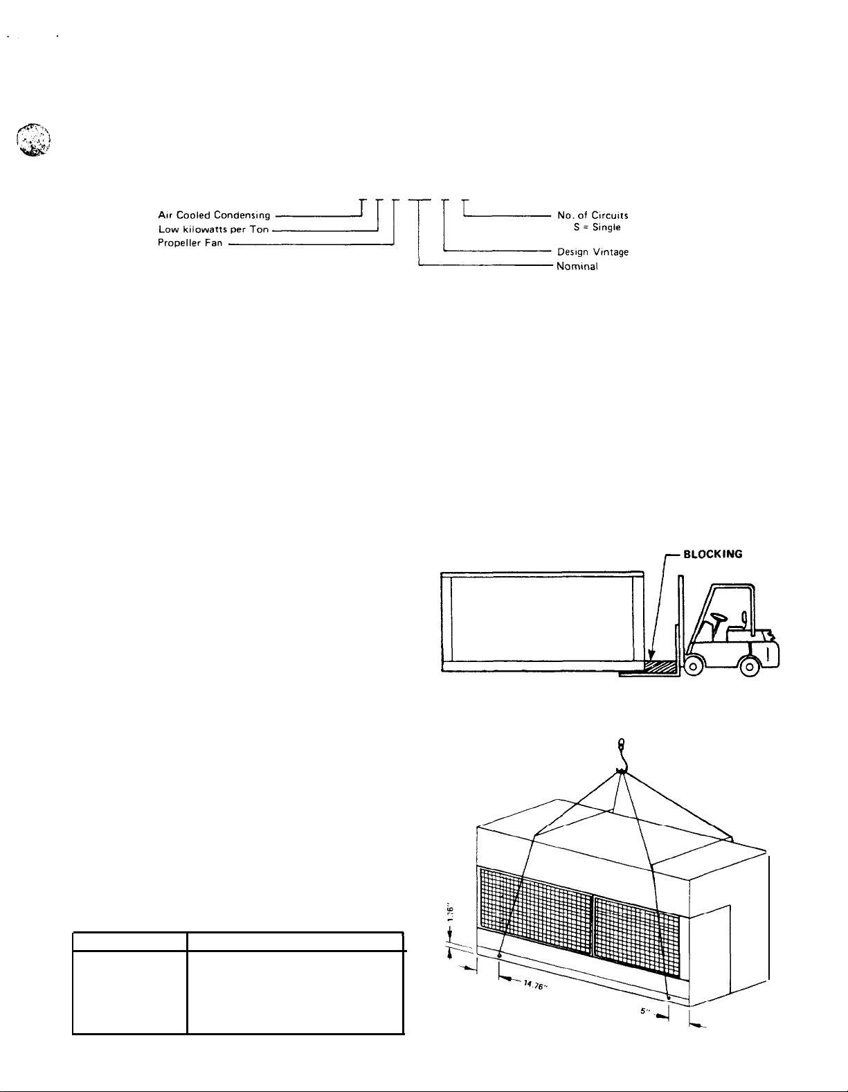
HANDLING
Care should be taken to avoid rough handling or shock due
to dropping the unit. Do not push or pull the unit from
anything other than the base, and block the pushing vehicle
away from the unit to prevent damage to the sheet metal
cabinet. (See Figure 1.)
To lift the unit,
provided in the base of the unit. Spreader bars and cables
should be arranged to prevent damage to the condenser
coils or unit cabinet. (See Figure 2.)
LOCATION
Due to vertical condenser design, it is recommended that
the unit is oriented so that prevailing winds blow parallel to
the unit length, thus minimizing effects on condensing
pressure. If it is not practical to orient the unit in this
manner, a wind deflector should be constructed.
Units are designed for outdoor application and may be
mounted on a roof or concrete slab (ground level
installation). Roof-mounted units should be installed level
on steel channels or an l-beam frame to support the unit
above the roof. Use of vibration pads or isolators is
recommended. The roof must be strong enough to support
the weight of the unit. See Table 1 for unit weights.
Concrete slabs used for unit mounting should be installed
level and be properly supported to prevent settling. A
one-piece concrete slab with footings extended below the
frost line is recommended.
TABLE 1. UNIT WEIGHTS
ALP MODEL
016A
019A
023A
027A
033A
2-1/2-inch
diameter lifting holes are
OPERATING WEIGHT (LBS.)
1122
1383
1471
1600
1866
reported to the carrier and a claim should be filed. The unit
serial plate should be checked before unloading the unit to
be sure that it agrees with the power supply available.
FIGURE 1.
GOOD PUSHING ARRANGEMENT -CABINET DAMAGE UNLIKELY
SUGGESTED PUSHING ARRANGEMENT
FIGURE 2.
-?
PAGE 3
Page 4
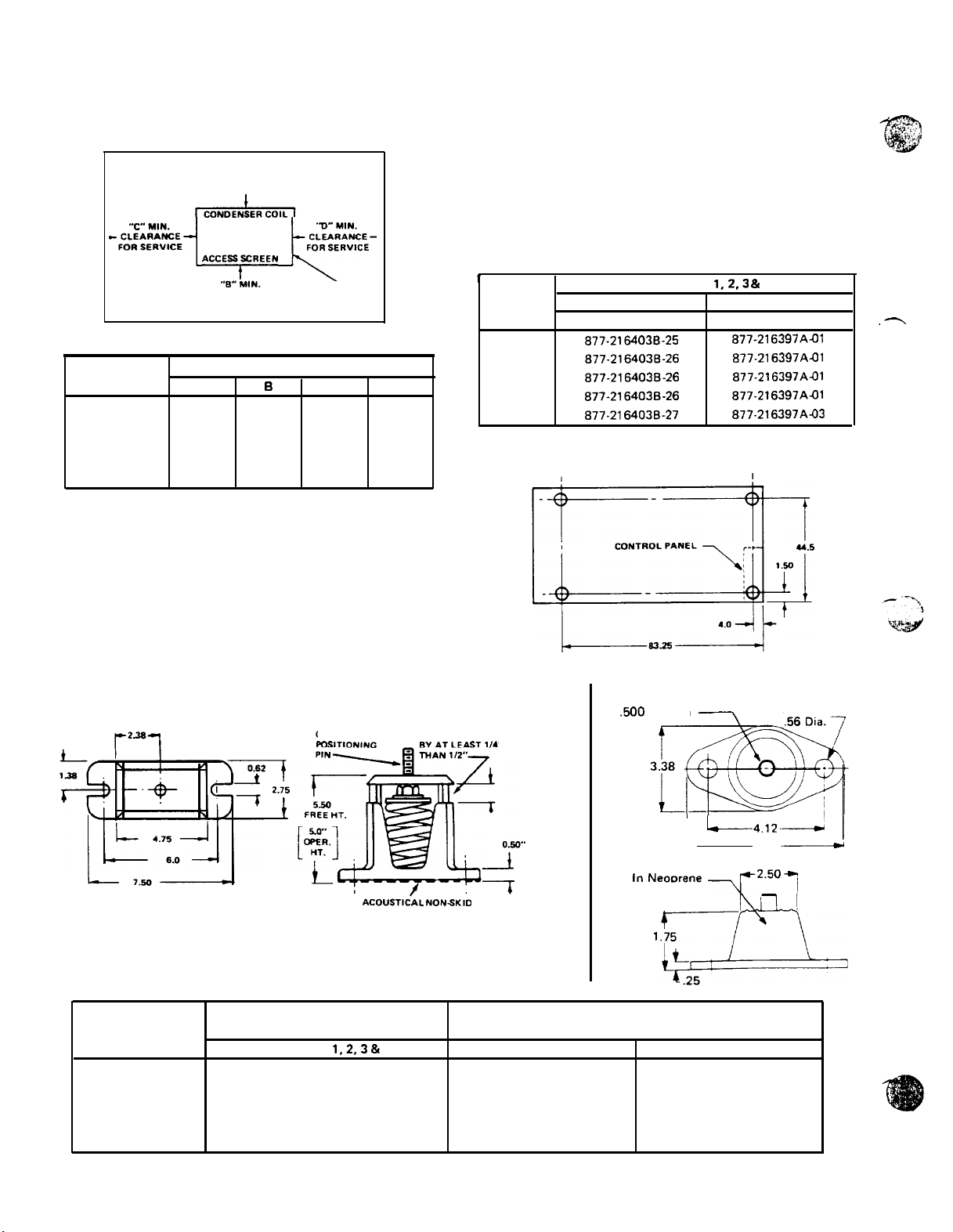
ACCESS
It is necessary to provide adequate clearance on all sides of
the
unit for service access and satisfactory performance.
Necessary clearances are shown in Figure 3.
VIBRATION ISOLATORS
Vibration isolators are recommended for all roof-mounted
installations or wherever vibration transmission is a
potential problem. Table 2 lists spring and rubber-in-shear
isolators for all ALP unit sizes. Table 3 shows isolator loads
FIGURE 3.
CLEARANCE AROUND UNIT
and the maximum allowable load for each isolator. Figure 4
shows isolator locations in relation to the unit control
“A-‘MIN.
CLEARANCE
FOR AIR INLET
panel. Figure 5 gives dimensions that are required to secure
each
Each unit base frame is provided with the necessary holes
to accept the
isolator.
-i%q
Acc~~~~~N
pQ%z-
TABLE 2.
’
ALP LOCATIONS
UNIT
SIZE ORDERING NUMBER
016A
019A
023A
027A
033A
FIGURE 4.
ALP
MODEL
016A
019A
023A
027A
033A
CLEARANCE
FOR DISCHARGE
DIMENSIONS (IN FEET)
A
3
3
3 5
3
3 6
CONTROL PANEL
0
4
4
5
C
3
3
3
3
3
D
4
4
4
4
4
McQUAY
isolator selection to the mounting surface.
0.50-inch
diameter positioning pin of each
ISOLATOR SELECTIONS
1,2.3
& 4
SPRING-FLEX
877-2164036-25
877-2164030-26
877-2164030-26
877-2164030-26
877-2164030-27
RUBBER-IN-SHEAR
ORDERING NUMBER
a77-216397Aal
877-216397A-01
877.216397AJJl
877-216397Aal
a77-216397A-03
ISOLATOR LOCATIONS
By removing the access screens, access can be gained to
the compressor, refrigerant lines, refrigerant components,
condenser fans and SPEEDTROL components. All other
controls are located in the unit control panel. They are
protected by a keylocked, weatherproof enclosure which
contains an internal “dead front” door for protection of
service personnel from high voltage starting controls while
servicing low voltage operational controls.
FIGURE 5.
ISOLATOR DIMENSIONS
(IN.)
Spring-Flex Isolators
ADJUST MOUNTING SO UPPER
HOUSING CLEARS LOWER
TABLE 3.
LATO R LOADS
IS0
0.50 DIA.
ACOUSTkAL NONSKlD
NEOPRENE PAD
HOUSING
AND NOT MORE
”
Rubber-In-Shear Isolators
,600
Dia. Pin
Mounting Molded
in
Neoorene
L4.12---
-\1’2.5”7
5.50
2 Holes
A
1
PAGE
ALP
UNIT
SIZE LOCATION
016A
019A
023A
027A
033A
4
ISOLATOR LOADS AT
EACH MOUNTING LOCATION
1.2,3
&
4 SPRING-FLEX
281
346
368
400
467
MAXIMUM LOADS ALLOWABLE
FOR EACH ISOLATOR SELECTION
RUBBER-IN-SHEAR
450
600
600
600
750
525
525
525
525
750
Page 5
REFRIGERANT PIPING
McQUAY
adaptable to either chilled water or air handling air
conditioning applications using refrigerant 22. Refrigerant
piping to and from the unit should be sized and installed
according to the latest
type ALP SEASONCON condensing units are
ASHRAE
Guide. The following
discussion is for use as a general guide to sound, economical
and trouble-free piping. The correct application of the
principles discussed here is the responsibility of the
installer.
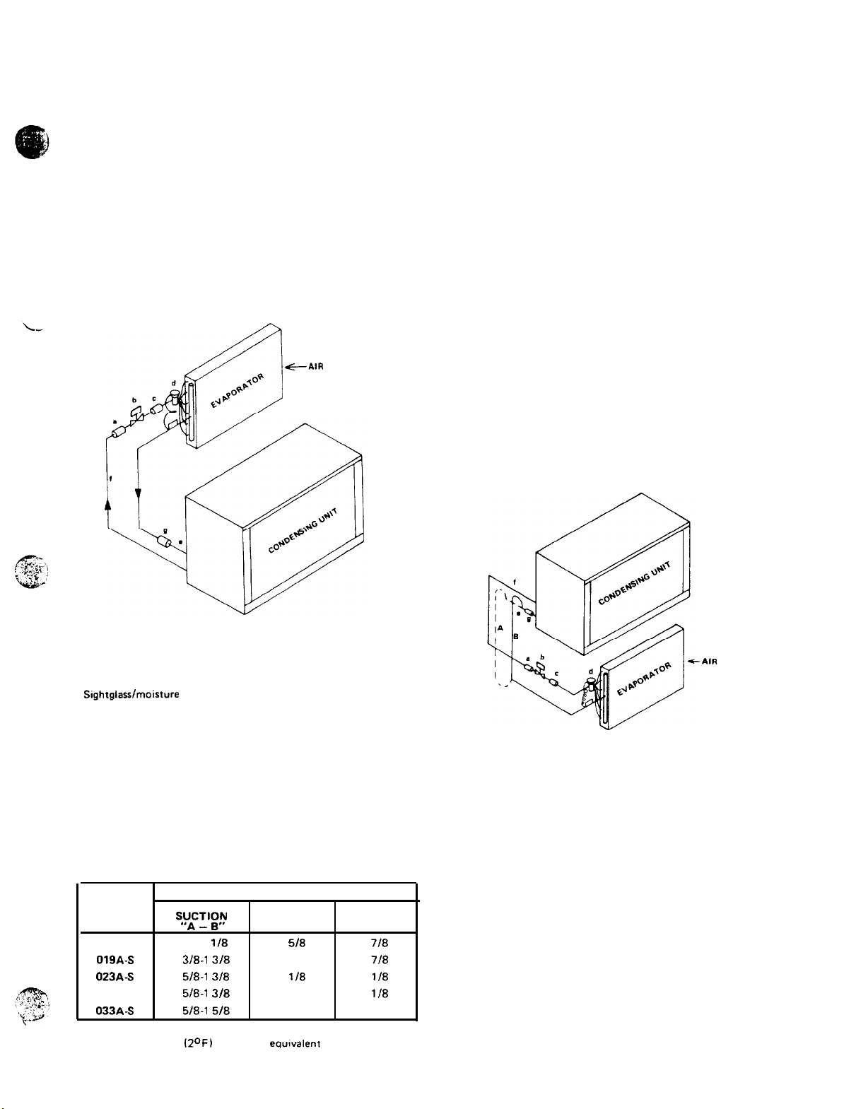
EVAPORATOR ABOVE CONDENSING UNIT
Figure 6 shows an installation where the evaporator is
installed above the condensing unit. It is shown for an air
handling installation, but all components shown are
recommended for chilled water installations except that a
refrigerant distributor is not usually required for
shell-and-tube evaporators.
FIGURE 6.
Evaporator Above Condensing Unit
-G-AIR
FLOW
EVAPORATOR BELOW CONDENSING
UNIT
Figure 7 shows an installation where the evaporator is
installed below the condensing unit. It is shown for an air
handling installation, but all components shown are
recommended for chilled water installations except that a
refrigerant
distributor is not usually required for
shell-and-tube evaporators. Note that a double suction riser
is shown for this arrangement.
Risers
“A + B”
are sized so that their combined
cross-sectional internal area will allow full load unit
operation without excessive pressure drop (see notes, Table
4). Riser
“B” is sized to provide adequate suction gas
velocity for proper oil return at minimum load conditions.
This riser becomes effective only when the trap shown in
riser “A” fills itself with oil. It should be emphasized that
the trap shown in riser “A” should be designed to contain a
minimum internal volume to keep the total system oil
requirements at a minimum. Table 4 gives recommended
line sizes for both single and double suction lines and for
liquid lines.
FIGURE 7.
Evaporator Below Condensing Unit
LEGEND
a Filterdrier
b Solenoid valve
c
Sightglasslmoisture indicator
d Thermal expansion valve
e
Suction line, pitched toward compressor
f Liquid line
g Vibration absorber
NOTES: All piping and piping components are by others.
TABLE 4.
ALP
UNIT
SIZE
016A-S
019A-S 1318-l 318 2118
023A-S 1518-l
027A-S 1518-l 318 2118 1l/8
033A-S 1518-l 518 2118 1 118
Note: Liquid and suction lines based on a recommended pressure
drop of 3 PSIG
RECOMMENDED LINE
DOUBLE
+y;.?l
1
118-l
l/8 1518
318 2 118 1l/8
12OF)
per 100 ft.
SINGLE
SUCTION
equrvalent
SIZE
LIQUID
718
718
length.
e-AIR
FLOW
LEGEND
a Filterdrier
b Solenoid valve
c
Sightglass/moisture
d Thermal expansion valve
e
Suction line, pitched toward compressor
f Liquid line
g
Vibration absorber
A+8 - Double suction riser (see note 2)
NOTES:
1. All piping and piping components are by others.
2. Trap for double suction riser should be as small in the
horizontal direction as fittings will allow.
indicator
REFRIGERANT PIPING CONNECTIONS
Refrigerant piping connections should be made through the
holes provided in the base frame on access screen side of
the unit.
PAGE 5
Page 6
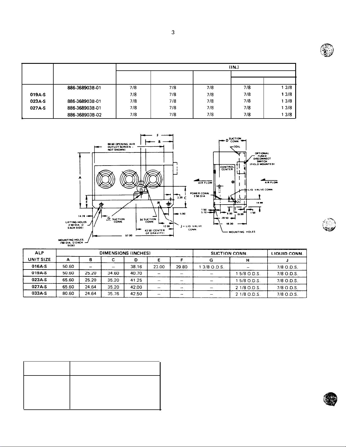
LIQUID LINE COMPONENTS
McQUAY
each ALP unit size. Table 5 shows the ordering number to
be used for each ALP unit size. The components included
in these kits are:
has available a “Liquid Line Accessory Kit” for
TABLE 5. LIQUID LINE ACCESSORY KITS
ALP LIQUID LINE
UNIT ACCESSORY KIT
SIZE ORDERING NUMBER
016A-S
019A-S
023A-S
027A-S
033A-S
,
886-368903641
886366903641
8863689039-01
886-368903841
aa6-36890384x2
FILTER-
DRIER VALVE GLASS
718 718
718
718 718 718
7/a 7/a 7/a
7ta
Replaceable core type filter-drier.
1.
Filter-drier core element.
2.
3
Refrigerant
Refrigerant
4:
Expansion valve.
5.
CONNECTION SIZES O.D.
SOLENOID SIGHT-
7/a
718 718
solenoid valve.
sightglass/moisture
(IN.1
7ta
7/a
indicator.
EXPANSION VALVE
IN
718
7/a
718
718
718
OUT
I
318
i
3/a
I
3/a
i
318
i
3/a
FIGURE 8.
DIMENSIONAL DRAWING
REFRIGERANT CHARGE
Each ALP condensing unit is designed for operation using
refrigerant 22. Table 6 lists refrigerant charge required for a
condensing unit/cooler combination.
TABLE 6. APPROXIMATE REFRIGERANT CHARGE
PAGE 6
ALP
MODEL
016A-S
019A-S
023A-S
027AS
033A-S
l
Refrigerant
will require
charge is for a
an additional charge.
‘R-22 REFRIGERANT
CHARGE (LBS.)
17
23
32
37
53
close-coupled
system. A remote cooler
ADDING REFRIGERANT CHARGE
On systems that have been
refrigerant, an
insufficient
previously
charge is indicated by bubbling
in the sightglass. On uncharged systems, the system should
be leak tested and evacuated before charging. Upon
charging
a system, the discharge and suction shut-off valves
on the compressor should be open and there should be
normal water flow through the cooler.
CAUTION: Do not make any safety controls inoperative
during the charging operation: cooler damage from freezing
may result.
1. Back seat the liquid line shut-off valve and connect the
charging hose to the
1/4-inch
flare connectron.
2. Install pressure gauges and review start-up instructions.
3. Purge the charging hose and open the
to allow refrigerant
into
the system.
charged with
charging
cylinder
Page 7
Turn the liquid line shut-off valve in three turns to
‘4.
permit a back flow of refrigerant into the subcooler.
After refrigerant stops flowing into the system, close the
5.
liquid line shut-off valve. Start the compressor to charge
the system.
If the amount of refrigerant has been predetermined,
6.
add this amount and check the sightglass afterward.
If the amount of charge is unknown, close the charging
cylinder valve every five minutes, open the liquid line
shut-off valve and check for proper charge by examining
the sightglass. Continue charging and checking the
sightglass until it is clear.
NOTE: Fluorocarbon refrigerants should not be released to
the atmosphere. For a means of recovery, refer to the
following section.
REMOVING REFRIGERANT CHARGE
To prevent freeze-up when removing the refrigerant for
ALP installations on water chiller systems, either drain the
water or circulate the water. If water cannot
make sure the cooler heater is energized. Do not remove
refrigerant rapidly since this can cause freeze-ups. Have a
sufficient number of refrigerant containers and a scale for
weighing them. The containers should be clean, dry and
empty.
gauge manifold from the compressor discharge valve service
port to the container and purge the iines. Note the capacity
of the container. Place the container in ice to cool the
container so the fusible plug does not melt as the
refrigerant condenses. Operate the compressor normally.
Turn the discharge service valve in three turns to open the
gauge manifold. Do not close off the discharge valve to the
condenser. Discharge gas can enter the container and
condense.
overfill. When the container is filled use additional ones.
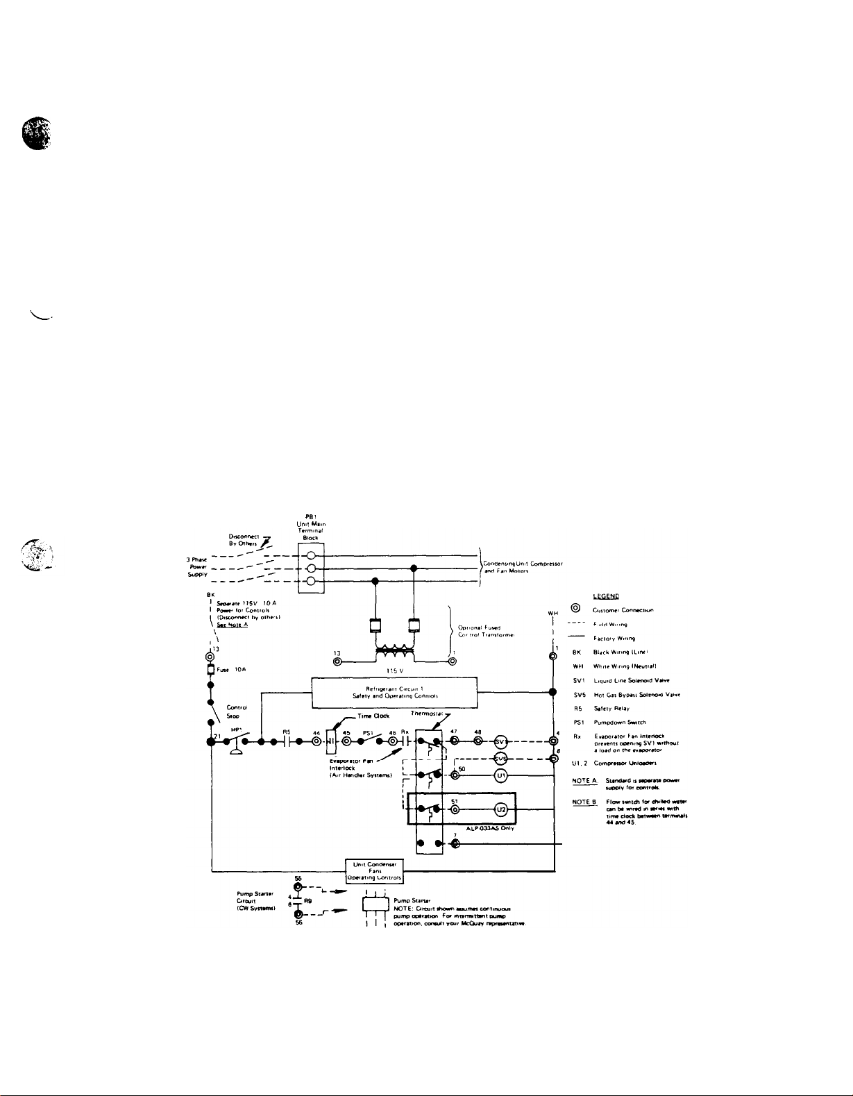
FIELD WIRING
WARNING: USE ONLY COPPER CONDUCTORS IN MAIN TERMINAL BLOCK.
Wiring should be done in accordance with all applicable
codes and ordinances. Warranty is voided if wiring is not in
accordance with specifications. An open fuse indicates a
short, ground or overload. Before replacing a fuse or
restarting a compressor or fan motor, the trouble must be
found and corrected.
All standard units require a 115 volt power supply for
the control circuit. If the optional control circuit
transformer is ordered, the control circuit is powered off
the main power supply.
unit installation. Items that require field wiring are liquid
line solenoid
and the cooling thermostat, as well as the unit power
supplies.
be
drained,
To transfer the refrigerant to a container, connect the
Frequently weigh the container so as not to
Figure 9 shows typical field wiring that is required for
SV1,
optional hot gas bypass solenoid
SV5
FIGURE 9.
TYPICAL FIELD WIRING
““ll Ml,”
PB1
,
Since it is impossible for
installation that an ALP condensing unit may be used on,
we do not factory install a thermostat. We do, however,
provide numbered terminals inside the unit control center
McQUAY
to anticipate the type of
THERMOSTAT WIRING
to which a thermostat may be connected. These terminals
are shown and labeled “Terminals For Thermostat” on the
electrical schematics. Figure 9 shows typical field wiring for
a thermostat with temperature controlled unloading.
PAGE 7
Page 8
Page 9

FLOW SWITCH FOR CHILLED WATER APPLICATIONS
A water flow switch or pump starter interlock is required
on chilled water applications to insure that there will be
adequate water flow and cooling load to the evaporator
before the unit can start.
slugging the compressors on start-up. It also serves to shut
down the unit in the event that water flow is interrupted to
guard against evaporator freeze-up.
A flow switch is available from
ordering number 860-175033X-00. It is a “paddle” type
This will safeguard against as shown in Figure 10.
McQUAY
under
switch and adaptable to any pipe size from l-inch to
6-inch
nominal. Certain minimum flow rates are required to close
the switch and are listed in Table 9. Installation should be
FIGURE 10.
,/ -
FLOW DIRECTION
HARKED ON SWITCH
TABLE 9. FLOW SWITCH MINIMUM FLOW RATES
SWITCH UPRIGHT
IN A HORIZONTAL
RUN OF PIPE
NO RESTRICTIONS
5 PIPE DIAMETERS MIN.
AFTER SWITCH
/
rJ
NO RESTRICTIONS
5 PIPE DIAMETERS MIN
BEFORE SWITCH
Electrical connections in the unit control center should
be made at terminals 12 and 21. The normally open
contacts of the flow switch should be wired between these
two terminals. There is also a set of normally closed
contacts on the switch that could be used for an indicator
light or an alarm to indicate when a “no flow” condition
exists.
EVAPORATOR FAN INTERLOCK FOR AIR HANDLER COIL INSTALLATIONS
It is important to interlock the air handler evaporator fan
with the condensing unit control center to insure that there
will be a cooling load on the evaporator before the unit can
start to prevent compressor slugging. A pair of terminals is
available in the unit control center for this purpose. These
terminal numbers are shown in Figure 9.
ELECTRICAL
CONTROL CENTER
All electrical controls are enclosed in a weatherproof
control center with a keylocked, hinged access door (see
Figure
11).
The left section is the largest and contains all of the 208,
230, 380 or 460 volt compressor and fan motor starting
controls. Also included in this section, but partitioned
separately, are the exposed terminal type, 115 volt
operational controls. A “dead front” cover over the left
section protects service personnel from high voltage starting
controls and exposed terminal operational controls.
panel, contains 115 volt adjustable or resettable controls.
bottom of the control center. Figure 11 shows a
recommendation for unit mounting arrangements if the
disconnect is to be unit mounted.
The control center is composed of two sections.
The right section, not covered by the “dead front”
Power supply conduits are intended to come into the
FIGURE 11.
IT DISCONNECT
CONTROL CENTER’
Page 10

Page 11

SkUENCE
The following sequence of operation is for an ALP
SEASONCON air cooled
circuit power on, control stop switch S1 closed and manual
pumpdown switch PS1 closed (“auto” position), 115 volt
power is applied through control circuit fuse
compressor crankcase heater
of low pressure switch LPI.
When the remote time clock, ambient thermostat,
manual shutdown switch and/or evaporator fan interlocks
energize the thermostatic circuit and, provided that high
pressure control
ALP-016A)
sense an alarm condition, safety relay R5 is energized
closed, applying power to temperature control thermostat.
At this point the unit will operate automatically in response
to the thermostat.
control thermostat
SV1,
the evaporator. As refrigerant pressure builds up, low
pressure control
R9
which closes to energize time delay TD14. The closing
of TD14 energizes fan motor relay Ml 1, closing its contacts
and providing power to condenser fan motor contactors
Mll,
thermostat
and normally open contact R21 is closed. Relay Ml is
energized and normally closed Ml AUX. contacts are open.
Compressor contactor Ml is closed and the compressor is
running at slow speed.
open, relay R21 is de-energized and normally closed
contact R21 is closed. On 208 volt and 230 volt units, relay
M9 is energized and normally open contacts M9 are closed.
Compressor contactors M9 (on 208 volt and 230 volt only)
and M5 are closed and the compressor is running at fast
speed.
cooling, temperature control thermostat
liquid line solenoid valve
allowing refrigerant to flow into the evaporator. As
refrigerant pressure builds up, low pressure control
closes, energizing low pressure relay R9 which closes to
energize compressor contactor Ml, starting the compressor.
Closing relay R9 contacts also energizes condenser fan relay
Ml 1, closing its contacts and providing power to condenser
fan motor contactors Ml 1, Ml2 and M13. At reduced load
conditions, thermostat
is energized and the compressor is unloaded. At full load
conditions, thermostat
de-energized and the compressor is loaded.
OF OPERATION
condensing unit. With control
HTR1
and also to the contacts
HP1,
and compressor motor protector
For ALP416
opening the valve and allowing refrigerant to flow into
Ml 2 and M13. At reduced load conditions,
TC1,
At full load conditions, thermostat
For
ALP-019,
oil pressure control
-
On a call for cooling, temperature
TC1
energizes liquid line solenoid valve
LP1
closes, energizing low pressure relay
stage 2, is closed, relay R21 is energized
023, 027 and 033 - On a call for
SV1,
opening the valve and
TC1,
stage 2, is closed, unloader
TC1,
stage 2, is open, unloader U1 is
OP1
MP1
TC1,
stage 2, is
TC1
energizes
F1
to the
(not on
do not
LP1
U1
PUMPDOWN
As the temperature control thermostat is satisfied, it opens
its contacts, de-energizing liquid line solenoid valve
causing the valve to close. When the compressor has
pumped most of the refrigerant from the evaporator to the
condenser, the low pressure control
down the compressor and condenser fan motors.
Should a closed
to the low
time, the buildup in pressure will cause the low pressure
control to close, energizing the low pressure relay and
starting
TABLE 10.
MODEL
NUMBER SIZE
I
NOTE: Condenser
SPEEDTROL motor.
CYCLE
LP1
solenoid
side
of the refrigerant circuit during unit “off”
the compressor for pumpdown.
MAJOR COMPONENT LOCATIONS
REAR VIEW OF UNIT
COIL ON OPPOSITE SIDE
COh4PRESSOR
valve allow refrigerant to leak
I
Fan
11
is location of optional
SV1,
opens, shutting
PAGE 11
Page 12

Page 13

Page 14

Page 15

Page 16

Page 17

START-UP & SHUT-DOWN
PRE START-UP
1.
With electrical disconnects open, check all screw or lug
type electrical connections to be sure they are tight for
good electrical contact. Check all compressor valve connections for tightness to avoid refrigerant loss at startup. Although all factory connections are tight before
shipment, some loosening may have resulted from shipping vibration.
A. On chilled water installations, check to see that all
2.
4.
water piping is properly connected.
B. Open all water flow valves and start the chilled
water pump. Check all piping for leaks and vent the
air from the evaporator and system piping. Flush
the evaporator and system piping to obtain clean,
non-corrosive water in the evaporator circuit.
Check the compressor oil level. Prior to start-up, the oil
3.
level should cover at least
Check the voltage of the unit power supply and see that
it is within the
voltage unbalance must be within &2%.
Check the unit power supply wiring for adequate
5.
ampacity and a minimum insulation temperature rating
of 75c.
Verify that all mechanical and electrical inspections
6.
have been completed per local codes.
See that all auxiliary control equipment is operative and
7.
that an adequate cooling load is available for initial
start-up.
INITIAL START-UP
1. Open the compressor suction and discharge shut-off
valves until back seated. Always replace valve seal caps.
2. Open the manual liquid line shut-off valve at the outlet
of the subcooler.
3. Allow the crankcase heater to operate for at least eight
hours prior to start-up.
4. Check to see that
“manual pumpdown” position and the control switch
S1 is in the “on” position.
5. Adjust the dial on the temperature controller to the
desired chilled water or leaving air temperature.
CAUTION: Most relays and terminals in the unit control
canter are hot with
on.
Throw the main power and control circuit disconnects
6.
to the “on” position.
7.
Start the auxiliary equipment for the installation.
Start the system by moving pumpdown switch PS1 to
8.
the “auto. pumpdown” position.
After system performance has stabilized, it is necessary
9.
that the “Compressorized Equipment Warranty Form”
(Form No.
warranty benefits. This form is shipped with the unit
and after completion should be returned to
Service Department through your sales representative.
TEMPORARY SHUT-DOWN
Move
pumpdown
position. After the compressors have pumped down, turn
RIO%
S1
206036A)
switch
1/2
of the oil sightglass.
tolerance that is allowed. Phase
pumpdown
and the control circuit disconnect
be completed to obtain full
PS1
switch PS1 is in the
to the “manual pumpdown”
McQUAY’s
off the chilled water pump or evaporator fan.
NOTE: With the unit left in this condition, it is capable
of recycling pumpdown operation. To defeat this mode of
operation, move the control stop switch
position.
It is especially important on chilled water installations
that the compressors pump down before the water flow to
the evaporator is interrupted to avoid freeze-up.
START-UP AFTER TEMPORARY SHUT-DOWN
Start the chilled water pump or evaporator fan.
With control stop switch
pumpdown switch PS1 to the “auto. pumpdown”
position.
Observe the unit operation for a short time to be sure
that the compressors do not cut out on low oil pressure.
EXTENDED SHUT-DOWN
Close the manual liquid line shut-off valve.
1.
After the compressor has pumped down, turn off the
2.
chilled water pump or evaporator fan.
3.
Turn off all power to the unit and to the auxiliary
equipment.
Move the control stop switch
4.
5.
Close the compressor suction and discharge valves.
6.
Tag all opened disconnect switches to warn against
start-up before opening the compressor suction and
discharge valves.
START-UP AFTER EXTENDED SHUT-DOWN
1.
inspect all auxiliary equipment (pumps, fans, etc.) to
see that each device is in satisfactory operating
condition.
2.
Remove all debris that has collected on the surface of
the condenser coils.
3.
Open the compressor suction and discharge valves.
4.
Open the manual liquid line shut-off valve.
5.
Check to see that
“manual pumpdown” position.
Turn on the electric power to the unit and other parts
6.
of the system.
Allow the crankcase heaters to operate for at least eight
hours prior to start-up.
On chilled water installations, start the chilled water
pump and purge the water piping as well as the
evaporator.
Check to see that the control stop switch
“on” position.
CAUTION: Most relays and terminals in the unit control
center are hot with
on.
Start the unit by moving
10.
“auto. pumpdown” position.
After running the unit tor a short time, check the oil
11.
level in the compressor crankcase and check for
flashing in the refrigerant sightglass.
S1
S1
in the “on” position, move
S1
pumpdown
and the control circuit
pumpdown
S1
to the “off”
to the “off” position.
switch PS1 is in the
S1
is in the
disconnect
switch PS1 to the
PAGE 17
Page 18

CONTROLS
OIL PRESSURE SAFETY CONTROL
ALP-OlSA, 023A, 027A,
The oil pressure safety control is a manually resettable
device which senses the differential between oil pressure at
the discharge of the compressor oil pump and suction
pressure inside the compressor crankcase. When the oil
pressure reaches approximately 15 PSI above the crankcase
suction pressure, the pressure actuated contact of the
control opens from its normally closed position. If this
pressure differential cannot be developed, the contact will
remain closed and energize a heater element within the
control. The heater element warms a normally closed
bimetallic contact and causes the contact to open,
de-energizing a safety relay and breaking power to the
compressor.
It takes about 120 seconds to warm the heater element
enough to open the bimetallic contact, thus allowing time
for the pressure differential to develop.
If during operation the differential drops below 10 PSI,
the heater element will be energized and the compressor
will stop. The control can be reset by pushing the reset
button on the control. If the compressor does not restart,
033A (NOT ON
ALP-OlGAI
allow a few minutes for the heater element and bimetallic
contacts to cool and reset the control again.
To check the control, pump down and shut off all
power to the unit. Remove the compressor relay wiring at
terminals 2 and 8, and install a voltmeter between terminals
L and M of the oil pressure control. Turn on power to the
unit control circuit (separate disconnect or main
disconnect, depending on the type of installation). Check
to see that the control stop switch
S1
is in the “on”
position. The control circuit should now be energized, but
with the absence of the compressor running, no oil pressure
differential can develop and thus the pressure actuated
contacts of the control will energize the heater element and
open the bimetallic contacts of the control within 120
seconds. When this happens the safety relay is de-energized,
the voltmeter reading will rise to
115V
and the compressor
contactor should open. Repeated operations of the control
will cause a slight heat build-up in the bimetallic contacts
resulting in a slightly longer time for reset with each
successive operation.
unit
LINE (SEE NOTE
LINE (SEE NOTE 2)
NOTES: 1. Hot only
1)
CONTACT
when
the
to run.
2. Hot only when other safety control contacts are closed.
L
M
41
I
unit
thermostat calls for compressor
NOTE: PERFORM AN OPERATIONAL CHECK ON ALL UNIT SAFETY CONTROLS ONCE PER YEAR.
SOLID STATE COMPRESSOR MOTOR PROTECTION
All air cooled condensing units have compressors with solid
state motor protection. Both Robertshaw and Texas
Instruments systems are used and their components are not
interchangeable.
There are two major components in a protection
system. First, the protector sensors are mounted internally
in the motor windings. The sensors monitor winding
temperature. A change in temperature causes a change in
sensor resistance. Sensor resistance is monitored by the
second component of the system
-
the control module
which is a sealed enclosure containing a relay, transformer
and other electronic components. Leads from the sensors
are connected to the module. Sensor resistance triggers the
control module relay at definite opening and closing
settings.
The module voltage will always be 120V and will be so
marked. When the control module needs repair no attempt
should be made to repair it. It should be returned intact for
replacement . If the module is opened or physically
damaged the warranty is void.
The control module and solid state sensor can be
damaged by high voltage. A high potential test should never
be made to the module or sensors.
If the compressor motor is not operating properly, the
following procedure may be used to check the solid state
motor control circuit.
I
1
y
BIMETALLIC CONTACTS
If the compressor has been operating and has been
1.
120
I
m
t
HEATER ELEMENT
stopped by the motor protector, allow one hour for the
compressor to cool and the motor protector to reset.
2.
If reset does not occur, connect a jumper wire across
the motor protector from terminal 30 to 36. If the
compressor does not operate with the jumper installed,
the problem is not within the solid state protector
system. If the compressor operates with the jumper
-
installed and does not operate without the jumper, the
control circuit relay in the module is open for some
reason.
CAUTION: Only check compressor operation with jumper
installed. Do not continue operation.
A possible cause of the open relay is the motor sensors.
They may be checked by first removing the connections to
the terminal board. Use an ohmmeter of 3 volt maximum
voltage to check resistance from each sensor terminal to the
common terminal. No voltage or current should be applied
to the sensors to check continuity. The resistance across
each motor sensor should be approximately 500 to 2400
ohms with a motor temperature below 1400F. If the
resistance is zero, there is a short. If the resistance is
infinity, there is an open connection.
NEUTRAL
NEUTRAL
SAFETY RELAY
PAGE 18
Page 19

On
reset the resistance of the sensors must be below the
reset point before the relay contacts will close. The reset
resistance is 2700 to 4500 ohms.
If the sensor resistance has been checked and found to be
satisfactory and the compressor will run with the control
bypassed but will not run with the control wired properly,
the control module is defective and must be replaced.
In case the resistance across a sensor is infinity, the
module will prevent compressor operation. As an
emergency means of obtaining compressor operation until
the compressor can be replaced, a resistor may be added
between the terminal of the open sensor and the common
terminal in the terminal box. The control module then
“sees” an acceptable resistance and compressor operation
will be restored. The emergency resistor should be 1 watt,
2200 ohms
provide the same degree of
reasonable measure of safety.
L
10% resistor. The emergency resistor will not
protection, but it provides a
RESIS
OPEN
L--L-
L-J
SENSORS
HIGH PRESSURE CONTROL
The high pressure control is a single pole pressure activated
switch that opens on a pressure rise to de-energize the
entire control circuit except for compressor crankcase
heater. It senses condenser pressure and is factory set to
open at 380 PSIG and can be manually reset closed at 315
PSIG. To check the control, block off condenser surface
and observe the cut-out point of the control by watching
. .
LOW PRESSURE CONTROL
The low pressure control is a single pole pressure switch
that closes on a pressure rise. It senses evaporator pressure
and is factory set to close at 60 PSIG and automatically
open at 25 PSIG. The control has an adjustable range of 20
rn. of Hg. to 100 PSIG and an adjustable differential of 6 to
40 PSIG. To check the control (unit must be running),
move the
pumpdown” position.
pumpdown
switch PS1 to the “manual
As the compressor pumps down,
SOLID STATE MODULE
1
l
condenser pressure rise. The highest point reached before
cut-out is the cut-out setting of the control.
CAUTION: Although there is an additional pressure
relief device in the system set at 425 PSIG, it is highly
recommended that the control stop switch S1 be close at
hand in case the high pressure control should malfunction.
condenser pressure will rise and evaporator pressure will
drop. The lowest evaporator pressure reached before
cut-out is the cut-out setting of the control. By moving the
pumpdown switch PS1 to the “auto. pumpdown” position,
evaporator pressure will rise. The highest evaporator
pressure reached before compressor restart is the cut-in
setting of the control.
FANTROL
FANTROL is a system for progressively turning on or off
condenser fans when they are no longer required.
done to reduce condenser capacity (typically in low
outdoor ambient temperatures) and is accomplished by a
combination of pressure and temperature actuated controls.
The first fan (No. 11) is started by its contactor when the
compressor in the unit starts. The second fan (No. 12) is
controlled by a pressure switch which senses condenser
pressure. The third fan (No. 13) is controlled by a
temperature switch which senses condenser air inlet
temperature. Pressure and temperature control setpoints are
indicated below.
To check the cut-in points of the controls, the unit
-
HEAD
This
is
PRESSURE CONTROL
must initially be off. With the unit prepared for start-up
according to the procedures outlined in this bulletin, move
pumpdown switch PS1 to the “auto. pumpdown” position.
Evaporator pressure will begin to rise and the compressor
should start with Fan 11 starting immediately. After the
compressor starts, observe condenser pressure as it rises.
When the condenser pressure reaches approximately 270
PSIG, contactor Ml2 should pull in to start Fan 12. On
three-fan units Fan 13 should start via contactor Ml3
whenever the ambient air at the condenser inlet reaches
8OF.
It may be difficult to check the cut-out point of Fan 13
(on three-fan units) at the instant it happens, but it should
be off whenever the ambient air at the condenser inlet is
below 70F. To check the cut-out point of Fan 12, some
means of reducing the load on the unit must be available or
the fan operation and condenser pressure must be observed
as the load drops off naturally. When the condenser
pressure drops to approximately 170 PSIG, contactor Ml2
should drop out to turn off Fan 12.
PAGE
19
Page 20

OPTIONAL CONTROLS
SPEEDTROL (OPTIONAL)
McQUAY’s
side of the control center, continuously varies No. 11 condenser fan motor speed on air cooled condensers by sensing
changes in refrigerant head pressure. SPEEDTROL makes
possible unit operation in lower ambient temperatures.
With an increase in refrigerant head pressure
TROL increases fan motor speed. With a decrease in pressure fan motor speed is decreased.
The pressure connection of the transducer is made to the
high pressure side of the refrigeration system at the purge
valve connection on the condenser coil header. This transducer coupled with a solid stage unit modulates the phase
Part winding start consists of a solid state time delay wired is energized instantly, while that for the second motor
in series with the contactor that energizes the second winding is delayed for one second.
winding of each compressor motor. Its purpose is to limit Control checkout is best accomplished by observation
current in-rush to the compressors upon start-up. As each
compressor starts, the contactor for the first motor winding
solid state SPEEDTROL, located on the back-
SPEED-
PART WINDING START (OPTIONAL)
conduction angle of the AC sine wave supplied to the fan
motor. The fan motor is a special
208/230V
SPEEDTAOL
motor. For 460 volt units a transformer is supplied to
decrease line voltage to 230 volt motor voltage. The
SPEEDTROL controller is calibrated to deliver 90% of line
voltage at the setpoint pressure of 230 PSIG. It has an
effective throttling range of 60 PSIG which is the decrease
in pressure below the calibration setpoint where 45% of
supply voltage is transmitted to the motor. When 45% of
supply voltage is transmitted to the motor, minimum motor
speed is reached; below this point there is no change in
speed.
as each contactor is pulled in to see that the one-second
delay occurs before the second contactor pulls in.
LINE
PART WINDING
TIME DELAY
LINE
+
1
LOW AMBIENT START (OPTIONAL)
Low ambient start is available on all units as an option with
F ANTROL and included automatically with optional
SPEEDTROL. It consists of a solid state normally closed
time delay wired in series with a relay. These are both wired
in parallel to the liquid line solenoid valve so that when the
solenoid valve is energized by the unit thermostat, the low
ambient start relay is
The relay has contacts that essentially short circuit the low
pressure control and allow the compressor to start with the
low pressure control open.
After about
de-energize the relay. If the system has not built up enough
evaporator pressure to close the low pressure control, the
compressor will stop. The time delay can be reset to its
original normally closed position by moving the
also energized through the time delay.
2-3/4
minutes, the time delay will open and
pumpdown
NEUTRAL
COMPRESSOR CONTACTOR
(1st
MOTOR WINDING)
NEUTRAL
COMPRESSOR CONTACTOR
(2nd MOTOR WINDING)
switch
the
PS1
to the “manual pumpdown” position. Moving
pumpdown
switch PS1 back to the “auto. pumpdown”
position will again energize the relay for another attempt at
start-up. If the system has built up enough evaporator
pressure, the compressor will continue to run.
To check the control, turn off all power to the unit and
remove the wire leading to the low pressure control
LP1
from terminal 11 in the unit control center. Remove the
wires leading from the contactors to the compressor and
jumper across terminals L and M of the oil pressure safety
control. Energize the control circuit by turning on the
control circuit disconnect or main power disconnect
(depending on the installation) and the control stop switch
S1.
The compressor contactors should pull in instantly.
PAGE
20
NOTE :
Line
is
only hot when the unit thermostat
calls
for compressor to run
Page 21

COMPRESSOR LOCKOUT (OPTIONAL)
Compressor lockout consists of a solid state time delay
wired in series with the compressor
contactor(
Its
purpose is to prevent rapid compressor cycling when
cooling
demands are erratic.
When the unit thermostat no longer calls for cooling
and the compressor
contactor(s)
have opened, the lockout
time delay breaks open the circuit preventing compressor
restart.
The circuit remains open for a period of five minutes so
that if the unit thermostat should call for cooling before
the delay period has expired, the compressor will not
restart. After five minutes, the time delay will close its
contacts to complete the circuit and be ready for start-up.
The time delay opens its contacts whenever there is power
to the terminals of the compressor relay and resets closed
automatically after the time delay period.
To check the control, the compressor must be running
initially.
pumpdown”
Move the pumpdown switch PS1 to the “manual
position. immediately after the compressor
has stopped running, move the
the “auto. pumpdown” position.
not restart for five minutes.
LINE
(SEE NOTE)
NOTE: Hot whenever freeze
cc,n,r~,
and hqh
pumpdown
switch back to
The compressor should
,xessure contrd permt
safe
~,xtatcr
It is expected
that the customer will want to locate the
ALARM BELL (OPTIONAL)
alarm bell where it will be heard in the event of a safety
failure. After mounting, the bell should be wired to
transformer T4. When the bell is wired into the control
HOT GAS BYPASS (OPTIONAL)
Hot gas bypass is a system for maintaining evaporator
pressure at or above a minimum value. The purpose for
doing this is to keep the velocity of the refrigerant as it
passes through the evaporator high enough for proper oil
return to the compressor when cooling load conditions are
light.
The system usually consists of a solenoid valve piped in
series with a pressure regulating valve as shown. Provisions
are provided for installing the hot gas bypass kit.
The solenoid valve should be wired to operate as close to
the unit’s maximum unloaded state as possible. The
pressure regulating valve that McQuay offers is factory set
to
being opening at 58 PSIG
(32F
for R-22) when the air
charged bulb is in an 80F ambient temperature. The bulb
can be mounted anywhere as long as it senses a fairly
constant temperature at various load conditions. The
compressor suction line is one such mounting location. It is
generally in the 50F to 60F range. The chart below
indicates that when the bulb is sensing 50F to 60F
temperatures, the valve will begin opening at 54 to 56
PSIG. This setting can be changed, as indicated above, by
changing the pressure of the air charge in the adjustable
bulb. To raise the pressure setting, remove the cap on the
bulb and turn the adjustment screw clockwise. To lower the
setting, turn the screw counter-clockwise. Do not force the
adjustment beyond the range it is designed for as this will
damage the adjustment assembly.
The regulating valve opening point can be determined
by slowly reducing the system load while observing the
suction pressure. When the bypass valve starts to open, the
refrigerant line on the evaporator side of the valve will
begin to feel warm to the touch.
CAUTION: The
hot gas line may become hot enough to
cause injury in a very short time, so care should be taken
during valve checkout.
On installations where the condensing unit is remote
from the evaporator, it is recommended that the hot gas
bypass valve be mounted near the condensing unit to
minimize the amounts of refrigerant that will condense in
the hot gas line during periods when hot gas bypass is not
required.
circuit it will sound whenever there is a failure due to
oil pressure (not on
ALP-OlGAI,
motor overload, or
excessive condenser pressure.
HOT GAS BYPASS PIPING DIAGRAM
Hot
Gas Bypass
Solenoid Valve
r
in ALP Unit
with Factory
Capped Tee for
Connection. A
manual shut-off
valve between the
bypass tee and
solenoid valve is
recommended.
Bypass Valve
y-
Surt1on
Line
External Equalizer
Expansion Valve
(On DX Coil with
Distributor, use
Sporlan Auxiliary
Sideport Connector
or Equivalent.)
HOT GAS BYPASS ADJUSTMENT RANGE
REMOTE BULB
80
30
40
30
52 6070
TEuP
ADJUSTMENT
f0F1
AT BULB LOCATION
RANGE
80
90
100
low
1,:
PAGE 21
Page 22

MAINTENANCE PROCEDURES
NOTE: Service on
must be investigated and corrected. CAUTION: Disconnect all power before doing any service inside the unit.
this equipment is to he performed by qualified refrigeration service personnel. Causes for repeated
tripping of Safety controls
On
Initial
be necessary to perform
Among these are checking the compressor
taking condensing, suction and oil pressure readings. During
operation the oil level should be
with the compressor running. On units ordered
The refrigerant sightglass should be observed periodically.
(A
of liquid indicates that there is adequate
in the system to insure proper feed through the expansion
valve. Bubbling refrigerant in the srghtglass indicates that
the system is short of
start-up and periodically
certain
monthly observation should be adequate.) A clear glass
refrigerant
during operation
routine service checks,
visible
in the oil sightglass
refrigerant
charge. On
it will
oil
level and
with
gauges,
REFRIGERANT SIGHTGLASS
charge
sightglasses
condensing,
gauges. Oil pressure gauge is not available on
The gauges are installed with a manual shut-off valve
each gauge line. The valves should be closed at all times
except when gauge readings are being taken.
ordered from
Accessory
what moisture condition corresponds to a
color. If the sightglass does not indicate a dry
after a few hours of operation, the unit should be pumped
down and the cores in the
suction
and
oil
pressures can be read from the
McQUAY
an element Inside the sightglass indicates
Kits”,
as part of the
filter-driers
changed.
FILTER-DRIERS
To change the filter-drier core, pump the unit down by
moving
position. Turn off all power to the
from terminal 31 to 34. Turn power to the
and restart the unit by moving
the “auto. pumpdown” position. Close the manual liquid
line shut-off valve and when evaporator pressure reaches 0 recommended after the core has been changed.
PSIG. move the control stop switch
The
automatic
not normally require any maintenance. It may, however,
require replacement of the solenoid coil or of the entire
valve assembly.
without
pumpdown
position. The
pumpdown
liquid
line solenoid valve, which is responsible for
pumpdown
The solenoid
opening the refrigerant
switch PS1 to the “manual pumpdown”
switch PS1 to the “manual pumpdown”
during normal
coil
may be removed from the valve body
coil
can then be removed from the valve bodv
unit
and install a jumper
pumpdown
unit
unit
switch PS1 to After core replacement, replace the cover plate. A leak
S1 to the “off”
LIQUID LINE SOLENOID VALVE
operation, does
piping
by moving
back on shell and replace the core.
position.
isolate
filter-drier.
check around the flange of the filter-drier shell is
by simply removing a nut or snap ring located at the top of
the coil. The coil can then be slipped off
for replacement. Be sure to replace the
stud before
pumpdown” position.
pumped down by use of the manual
valve.
This will
the short section of refrigerant
To replace the
close the
Remove the cover plate from the
returning pumpdown
entire
liquid
line solenoid valve and
piping
its mounting
coil
on its mounting
switch PS1 to the “auto.
solenoid valve, the unit must be
liquid
ALP-OIGA.
on
"Liquid
Line
given
element
condition
containing the
filter-drier
stud
line shut-off
CONDENSERS
Condensers are air cooled and constructed
copper tubes bonded in a staggered pattern
aluminum fins. No maintenance IS
except the occasional removal of dirt and debris from the
with 3/8
ordinarily
O.D.
into
rippled
required
outside surface of the fins. Care should be taken not to
damage the fins during cleaning. Periodic use of the Purge
valve on
non-condensables.
COMPRESSOR OIL LEVEL
Because of the large refrigerant charge required in an air At the present
cooled condensing unit it IS usually necessary to put approved by
additional
watched carefully upon
thereafter.
oil
into the system. The oil level should be
initial
start-up and for
sometime
compressors. The oil level should be
the
midpoint
use of a light may be required for proper
ADDING OIL TO COMPRESSOR
Oil may be added to the
011 1111
hole in the crankcase
compressor through the
of the compressor. To add
pour or pump the necessary
no
rcfrrgerant.
than keeping the
If the system contains a refrigerant charge, close the
suction valve and reduce crankcase pressure to 1 to 2 PSIG.
PAGE 22
no special
oil
Copeland
3/8-Inch
precautrons
clean and
compressor through the Stop the compressor and close the discharge valve.
and
to the Sundstrand
process tube on the side compressor IS exposed to the atmosphere the refrigerant
011,
Isolate the crankcase and
011
in. If the system
are necessary other
dry.
contains
Add the
will
qeneratc a vapor pressure,
contamrnants.
crdnkcasr! by
seconds. Close the
restore the system to operation.
the condenser will prevent the build-up of
time,
Copeland
of the sightglass on the compressor body. The
requrred
Before resealing the compressor purge the
openrnq
Suniso 3GS
and Sundstrand for use in these
amount of
retarding
the suctrorr valve slightly for 1 or
oil
port, open
the
oil
is the only oil
maintained
oil
011. Durirrg
the entrance Of
compressor valves and
at about
level reading.
the
perrod the
2
.I.
Page 23

I
ELECTRICAL TERMINALS
CAUTION: ELECTRIC
SHOCK HAZARD -TURN OFF ALL POWER BEFORE CONTINUING WITH
FOLLOWING SERVICE.
All
power electrical terminals should be retightened every six months, as they tend to loosen in service
due to normal heating and cooling of the wire.
FAN MOTOR BEARINGS
All
fan motors are pre-lubricated and do not require the addition of grease.
THERMOSTATIC EXPANSION VALVE
The expansion valve is responsible for allowing the proper
amount of refrigerant to enter the evaporator, regardless of
cooling load. It does this by maintaining a constant
superheat. (Superheat is the difference between refrigerant
temperature as it leaves the evaporator and the saturation
temperature corresponding to the evaporator pressure.)
Typically, superheat should run in the range of
On valves purchased through McQUAY, the superheat
setting can be adjusted by removing a cap at the bottom of
the valve to expose the adjustment screw. Turn the screw
clockwise (when viewed from the adjustment screw end) to
increase the superheat setting and counter-clockwise to
reduce superheat. Allow time for system rebalance after
each superheat adjustment.
The expansion valve, like the solenoid valve, should not
normally require replacement, but if it does, the unit must
be pumped down by using the manual liquid line shut-off
valve. If the problem can be traced to the power element
only, it can be unscrewed from the valve body without
removing the valve, but only after pumping the unit down
with the manual liquid line shut-off valve.
10F
to 15F.
‘POWER ELEMENT
(CONTAINS DIAPHRAGM)
IN1.ET
OUTLET
SPRING
ADJUSTMENT SCREW
IN-WARRANTY RETURN MATERIAL PROCEDURE
COMPRESSOR
Bristol Corporation [compressor used in the ALP-0161, and
Copeland Corporation [all other units], have stocking
wholesalers who maintain a stock of replacement compressors and service parts to service refrigeration contractors
and servicemen.
When a compressor fails in warranty, contact your local
sales representative or McQuay Warranty Claims Department at the address on the cover of this bulletin. You will
be authorized to exchange the defective compressor locally
(an advance replacement can be obtained), or we will ship
you a replacement from our stock. A salvage credit is issued
to you by the wholesaler on the returned compressor after
COMPONENTS OTHER THAN COMPRESSORS
Material may not be returned except by permission of
authorized factory service personnel of McQUAY Inc. at
Minneapolis, Minnesota. A “Return Goods” tag will be sent
to be included with the returned material. Enter the
information as called for on the tag in order to expedite
handling at our factories and prompt issuance of credits.
The return of the part does not constitute an order for
replacement. Therefore, a purchase order must be entered
through your nearest McQUAY Representative. The order
Bristol or Copeland factory inspection of the inoperative
compressor. Provide McQuay with full details and invoices
and we will reimburse the difference. In this transaction, be
certain that the compressor is definitely defective. If a
compressor is received from the field that tests satisfactor-
ily, a service charge plus a transportation charge will be
charged against its original credit value.
Copeland offer the same field facilities for service and/or
replacement as described above. The credit issued by Bristol
or Copeland on the returned compressor will be determined
by the repair charge established for that particular unit.
should include part name, part number, model number and
serial number of the unit involved.
and if it is determined that the failure is due to faulty
material or workmanship and in warranty, credit will be
Issued
McQUAY factory, transportation charges prepaid.
CAP
On all out-of-warranty compressor failures, Bristol and
Following our personal inspection of the returned part,
on customer’s purchase order.
All parts shall be returned to the pre-designated
PAGE 23
Page 24

 Loading...