

Installation and Operation Manual
Packaged Air-Cooled Condensing Units
Models ALP-012D - ALP-019D
50 and 60 Hertz
IM 687
Group: Chiller
Part Number: 629950
Date: January 1997
Supersedes: None
© 1997 McQuay International

Table of Contents
INTRODUCTION.............................3
INSPECTION ...................................3
INSTALLATION..............................3
Handling....................................................3
Location.....................................................4
Service Access...........................................5
Refrigerant Piping ............................5
General......................................................5
Refrigerant Piping .....................................5
Application Considerations..............6
Water Piping .............................................. 8
Flow Switch ............................................. 10
Initial Start-up................................11
Holding Charge ....................................... 11
Leak Testing............................................ 11
Evacuation............................................... 11
Charging The System............................... 11
Refrigerant Charge ..................................12
Pre-Startup ..............................................12
Startup ..................................................... 13
Dimensional Data............................14
Physical Data................................... 16
Field Wiring....................................19
Electrical Legend.....................................21
Normal Sequence Of Operation.....22
Startup.....................................................22
Pumpdown...............................................22
System Maintenance .......................23
General....................................................23
Fan Motor Bearings .................................23
Electrical Terminals.................................23
Condensers ..............................................23
Refrigerant Sightglass..............................23
Service.............................................24
Thermostat Expansion Valve....................24
Filter-Driers.............................................24
Liquid Line Solenoid................................24
Standard Controls ..........................25
High Pressure Control..............................25
Low Pressure Control ...............................25
Compressor Lockout ................................25
Compressor Motor Protector ....................26
Fantrol Head Pressure Control .................26
Optional Controls...........................27
Speedtrol Head Pressure Control..............27
Low Ambient Start...................................27
Hot Gas Bypass........................................27
Electrical Data................................. 17
“McQuay” is a registered trademarks of McQuay International.
©1997 McQuay International
“Illustrations cover the general appearance of McQuay International products at the time of publication and
we reserve the right to make changes in design and construction at anytime without notice.”
2 ALP 012D through 019D IM 687
Troubleshooting Chart....................29
INTRODUCTION
ALP air-cooled condensing units are designed for outdoor installations and are compatible with
either air handling units or chilled water evaporators. Each unit is completely assembled and
factory wired before evacuation, charging and testing. Each unit consists of an air-cooled condenser
with integral subcooler section, tandem scroll compressors, complete discharge piping and suction
and liquid connections for connect to any air or water cooling evaporator.
INSPECTION
When the equipment is received, check all items against the bill of lading and inspect for damage
upon arrival. Report all shipping damage to the carrier and file a claim. In most cases, equipment
is shipped fob factory and claims for freight damage should be filed by the consignee. Check the
unit serial plate before unloading the unit to be sure that it agrees with the power supply available.
INSTALLATION
Note: Installation and maintenance are to be performed only by qualified personnel who
are familiar with local codes and regulations, and experienced with this type of equipment.
CAUTION
Sharp edges and coil surfaces are a potential injury hazard. Avoid contact with them.
Handling
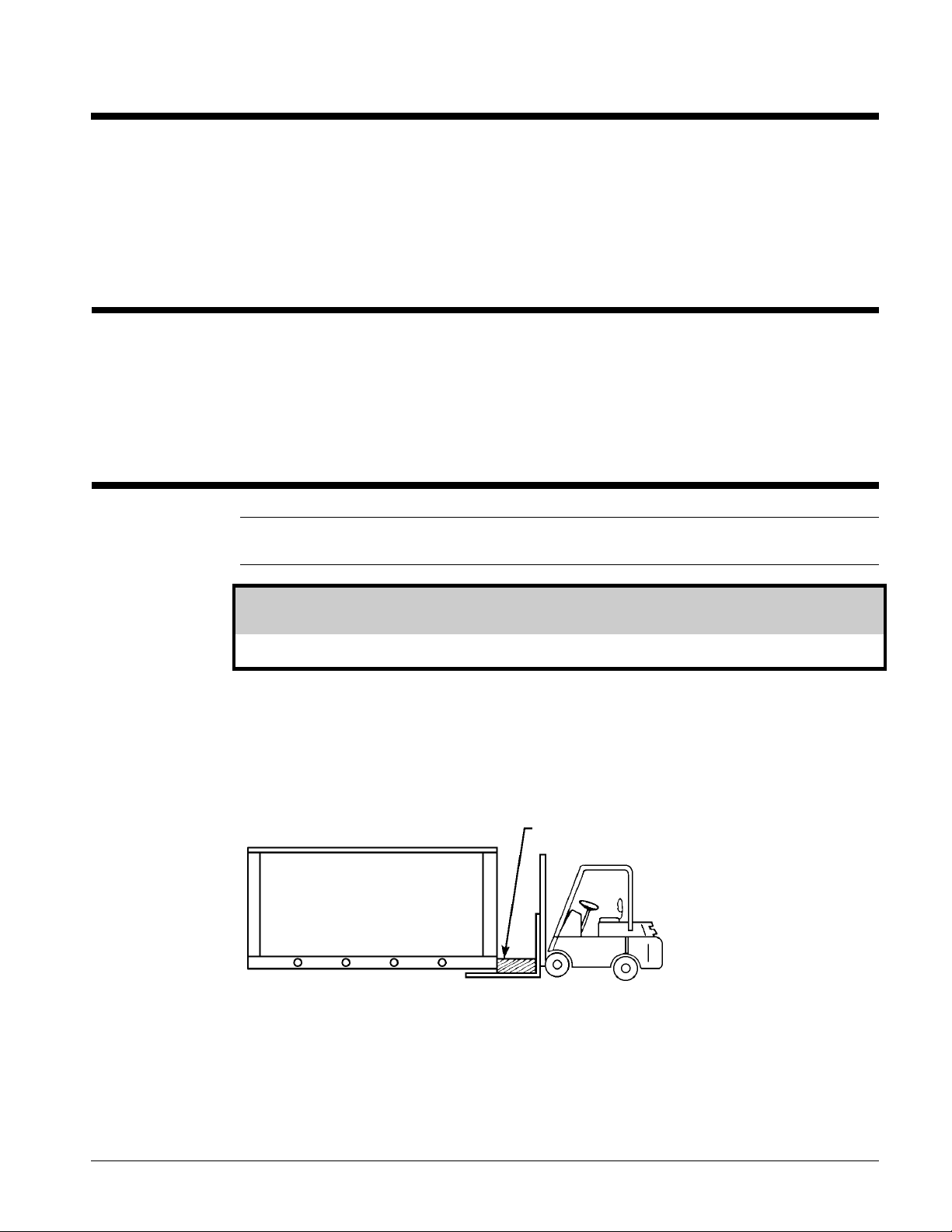
Be careful to avoid rough handling of the unit. Do not push or pull the unit from anything other
than the base. Block the pushing vehicle away from the unit to prevent damage to the sheet metal
cabinet and end frame See Figure 1.
Figure 1, Suggested pushing arrangement
Blocking required
across full width
Lifting slots are provided in the base of the unit. Arrange spreader bars and cables to prevent
damage to the condenser coils or cabinet). See Figure 2.
IM 687 ALP 012D through 019D 3
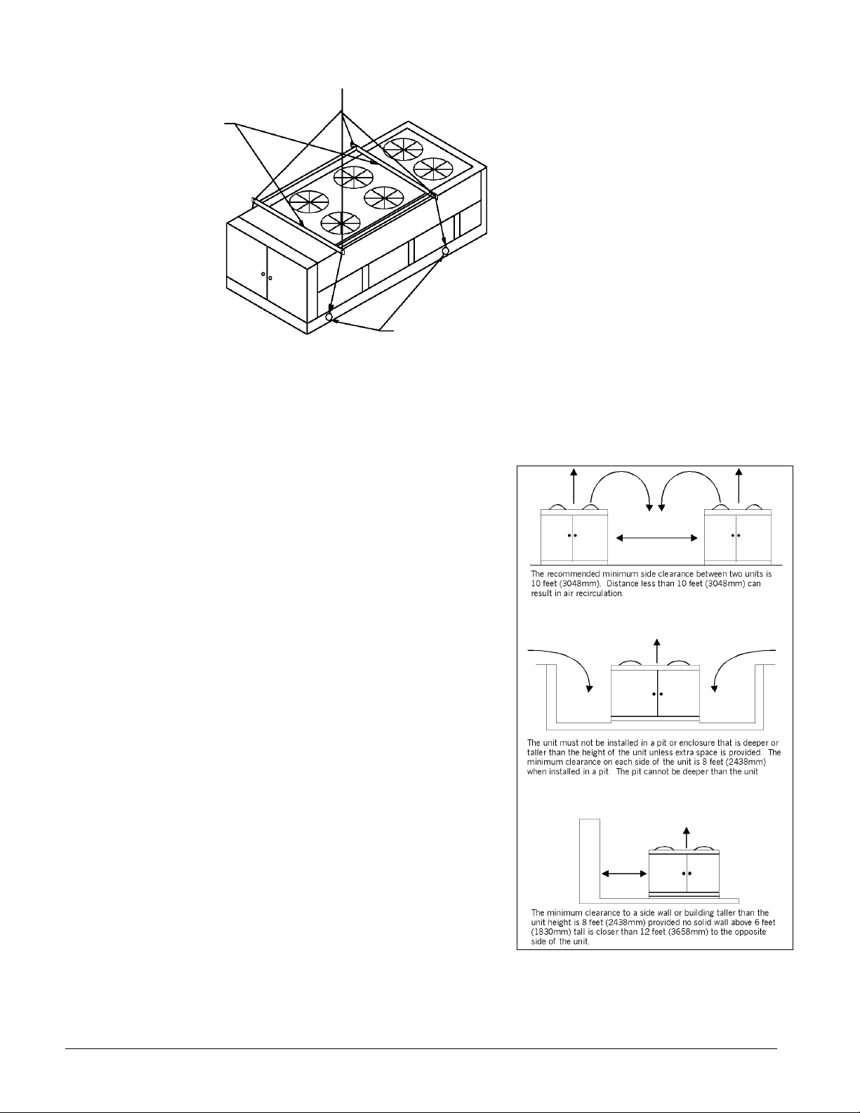
Figure 2, Suggested lifting arrangement
Spreader bars
recommended
(Use Caution)
Location
Unit Placement
ALP units are for outdoor applications and can be mounted on a roof or ground level. Set units on a
solid and level foundation. For roof mounted
applications, install the unit on a steel channel or Ibeam frame to support the unit above the roof. For
ground level applications, install the unit on a
substantial base that will not settle. A one piece
concrete slab with footings extended below the frost
line is recommended. Be sure the foundation is
level (within 1/2” [13 mm] over its length and
width). The foundation must support the operating
weights listed in the Physical Data tables beginning
on
page 16.
NOTE: Number of fans can vary
from this diagram. Lifting method
remains the same.
Must use these rigging holes.
(Be aware of contol box location.)
On ground level applications protect fins
against vandalism using the optional coil guards or
by erecting a screen fence. The fence must allow
free flow of air to the condenser coil for proper unit
operation.
Unit operation is affected by wind. Located the
unit so length is parrallel with the prevailing wind.
If this is not practical, use wind deflectors.
Clearances
The flow of air to and from the condenser coil must
not be limited. Restricting air flow or allowing air
recirculation will result in a decrease in unit
performance and efficiency. There must be no
obstruction above the unit that would deflect
discharge air downward where it could be
recirculated back to the inlet of the condenser coil. The condenser fans are propeller type and will
not operate with ductwork on the fan outlet.
4 ALP 012D through 019D IM 687
Install the unit with three feet of side clearance for air entrance to the coil and for servicing.
Provide four feet of service access at each end to access the evaporator, compressors, electrical
control panel and piping components.
Do not allow debris to accumulate near the unit. Air movement may draw debris into the
condenser coil causing air starvation. Give special consideration to low ambient operation where
snow can accumulate. Keep condenser coils and fan discharge free of snow or other obstructions to
permit adequate airflow.
Service Access
Each end of the unit must be accessible after installation for periodic service. Compressors, filterdriers, and manual liquid line shutoff valves are accessible from the end of the unit. High pressure,
low pressure, and motor protector controls are on the compressor. Most operational, safety and
starting controls are located in the unit control box.
The condenser fan and motors can be removed from the top of the unit.
Refrigerant Piping
General
Piping design, sizing and installation information presented in ASHRAE Handbooks should, where
applicable, be followed in the design and installation of piping. ALP condensing units are adaptable
to either chilled water or air handling air conditioning applications. The only restriction on
applications is that the evaporator be selected for a system using refrigerant R-22.
Refrigerant Piping
Design and install piping between the condensing unit and the cooling coil to minimize pressure
drop, prevent liquid refrigerant carryover to the compressor and to assure a continuous return of
compressor oil from the system. Piping sketches and tables are not intended to provide information
on all of the possible arrangements.
Piping recommendations include:
1. The use of type K or L clean copper tubing. Thoroughly clean and braze all joints with high
temperature solder.
2. Piping sizes should be based on temperature/pressure limitations as recommended in the
following paragraphs. Under no circumstances should pipe size be based upon the coil or
condensing unit piping connection size.
3. Suction line pressure drop should not exceed the pressure equivalent of 2° (3 psi) per 100 feet of
equivalent pipe length. After the suction line size has been determined, the vertical suction
risers should be checked to verify that oil will be carried up the riser and back to the
compressor. The suction line should be pitched in the direction of refrigerant flow and
adequately supported. Lines should be free draining and fully insulated between the evaporator
and the compressor. Table 3, shows piping information for units operating at suction
temperatures between 40°F and 45°F and a condenser entering air temperature of 95°F. If
operating conditions are expected to vary substantially from these operating levels, the pipe
sizing should be rechecked.
4. Vertical suction risers should be checked using Table 1 to determine the minimum tonnage
required to carry oil up suction risers of various sizes.
5. The liquid line should be sized for a pressure drop not to exceed the pressure equivalent of 2°F
(6 psi) saturated temperature.
IM 687 ALP 012D through 019D 5
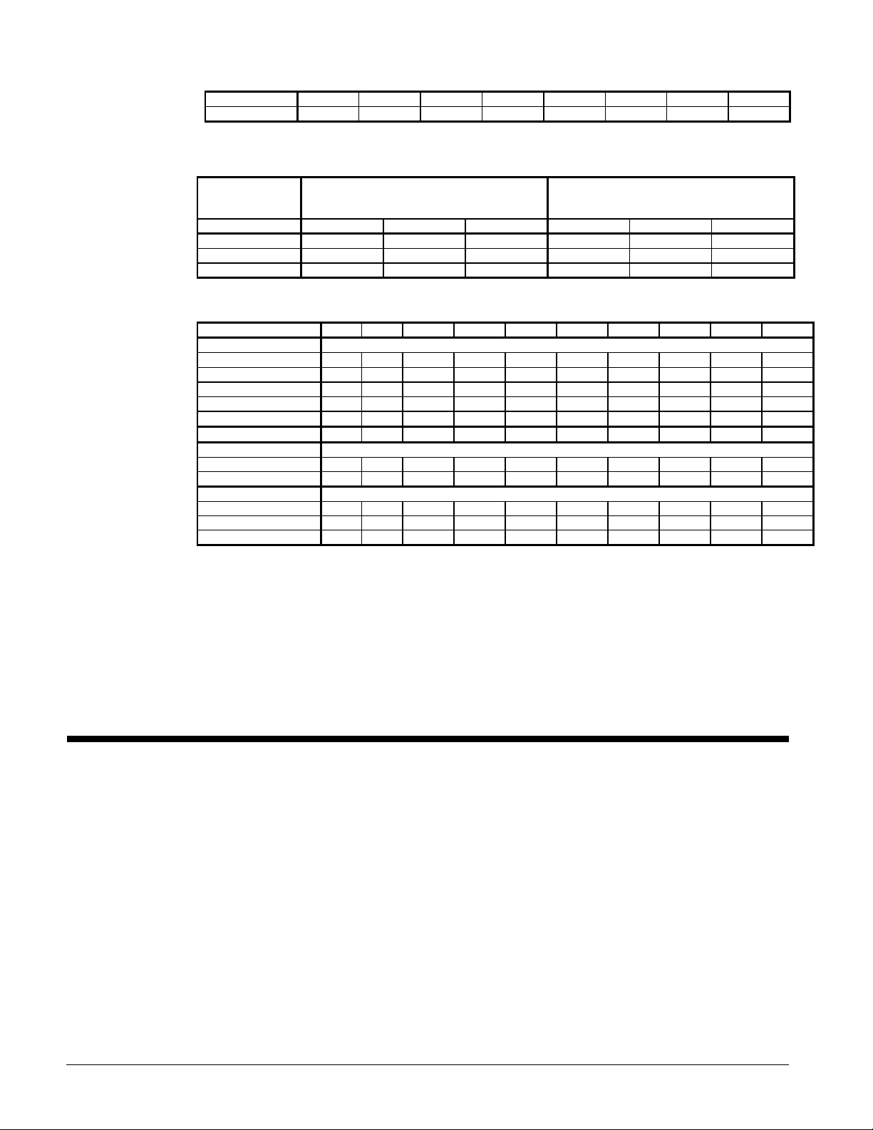
Table 1. Minimum tonnage to carry oil up suction riser at 40°°F saturated suction.
Line Size 1 1/8 1 3/8 1 5/8 2 1/8 2 5/8 3 1/8 3 5/8 4 1/8
Min. Tons 1.50 2.50 3.80 7.60 13.10 20.40 29.70 41.30
NOTE: When compressor minimum tonnage is less than shown in the above table for a given line size, reselection of risers will be
required or hot gas bypass at the coil will be required.
Table 2, Recommended line sizes (Max. equivalent feet of copper tubing*)
MODEL
NUMBER
1 3/8” 1 5/8” 2 1/8” 5/8” 7/8” 1 1/8’
012D 70 160 -- 35 200 -015D 35 80 300 16 100 365
019D -- 50 180 -- 60 220
*Equivalent line lengths in the above table are suitable for a unit operating at 40°F sat. suction, 50°F return gas and 95°F ambient.
SUCTION
LINE SIZE
O.D. COPPER
LIQUID
LINE SIZE
O.D. COPPER
Table 3. Equivalent feet of straight tubing for copper fittings and valves
FITTING TYPE 5/8” 7/8” 1 1/8” 1 3/8” 1 5/8” 2 1/8” 2 5/8” 3 1/8” 3 5/8” 4 1/8”
ELBOWS
90° Standard
90° Long Radius
90° Street
45° Standard
45° Street
180° BEND
TEES
Full Size 1.0 1.4 11.7 2.3 2.6 3.3 4.1 5.0 5.9 6.7
Reducing 1.6 2.0 2.6 3.3 4.0 5.0 6.0 7.5 9.0 10
VALVES
Globe Valve, Open 18 22 29 38 43 55 69 84 100 120
Gate Valve, Open 0.7 0.9 1.0 1.5 1.8 2.3 2.8 3.2 4.0 4.5
Angle Valve, Open 7. 9. 12 15 18 24 29 35 41 47
Notes:
1. Liquid and suction lines based on a recommended equivalent pressure drop of 2°F (3 psi for suction line, 6 psi for liquid line)
per 100 ft. of equivalent length.
2. When the refrigerant required to charge a system exceeds the pumpdown capacity of the unit plus the capacity of the liquid
line (see Table 4), the use of separate refrigerant storage receiver will be required. The pumpdown capacity of each unit is
based on the condenser 90% full at 90°F (see physical data).
3. Total equivalent feet for a given piping layout must include the equivalent length of straight pipe for fittings, valves and
specialties added to the total run of straight pipe.
4. Piping design, sizing an installation information presented in ASHRAE Handbooks should, where applicable, be followed in the
design and installation piping.
5. Units running at 50% load do not require double suction risers.
1.6 2.0 2.6 3.3 4.0 5.0 6.0 7.5 9.0 10
1.0 1.4 1.7 2.3 2.6 3.3 4.1 5.0 5.9 6.7
2.5 3.2 4.1 5.6 6.3 8.2 10. 12 15 17
0.8 0.9 1.3 1.7 2.1 2.6 3.2 4.0 4.7 5.2
11.3 1.5 2.1 3.0 3.4 4.5 5.2 6.4 7.3 8.5
2.5 3.2 4.1 5.6 6.3 8.2 10 12 15 17
Application Considerations
Suction Accumulators
Field experience indicates that as the refrigerant charge in a small tonnage system increases, the
potential stress level from liquid floodback during system startup and stabilization also increases.
Since there is no factory control of condensing unit applications, piping and design, a suction
accumulator is recommended. The accumulator’s function is to intercept liquid refrigerant before it
reaches the compressor crankcase causing mechanical damage. It should be located in the suction
line between the evaporator and compressor, have a refrigerant capacity large enough to hold the
maximum amount of refrigerant that could flood through, and must have provisions for a positive
return of oil to the crankcase.
VAV Direct Expansion Systems
Variable air volume (VAV) application to direct expansion cooling coil systems is increasingly
attractive because of the potential energy savings in fan motor power. Extra care must be exercised
in the design of VAV direct expansion systems because of the potential for coil icing, oil trapping,
loss of stable expansion valve control, excessive compressor cycling, and nuisance operation of
protective controls.
6 ALP 012D through 019D IM 687
Equipment damage and nuisance tripping can be avoided by proper total system design. Special
consideration must be given to reduced load operating conditions as well as peak design, and coil
selection, capacity unloading, and system control modified as required to provide a trouble-free
system.
Head Pressure Control
Condenser coils on these ALP condensing units are vertical in position and are subject to wind. The
standard head pressure control offered controls the operation or speed of condenser fans. This type
of control has no effect if condenser coils are subjected to wind.
The design engineer or contractor has the responsibility of locating the equipment or protecting
the condenser coil so that prevailing winds have minimum effect on unit performance.
Oil Charge
Excessive piping or refrigerant charge or both may require the addition of some oil to the
compressor. If additional oil is required, use Suniso brand for the Copeland compressors. Add only
enough oil to maintain an oil level at the indicated point in the compressor sightglass.
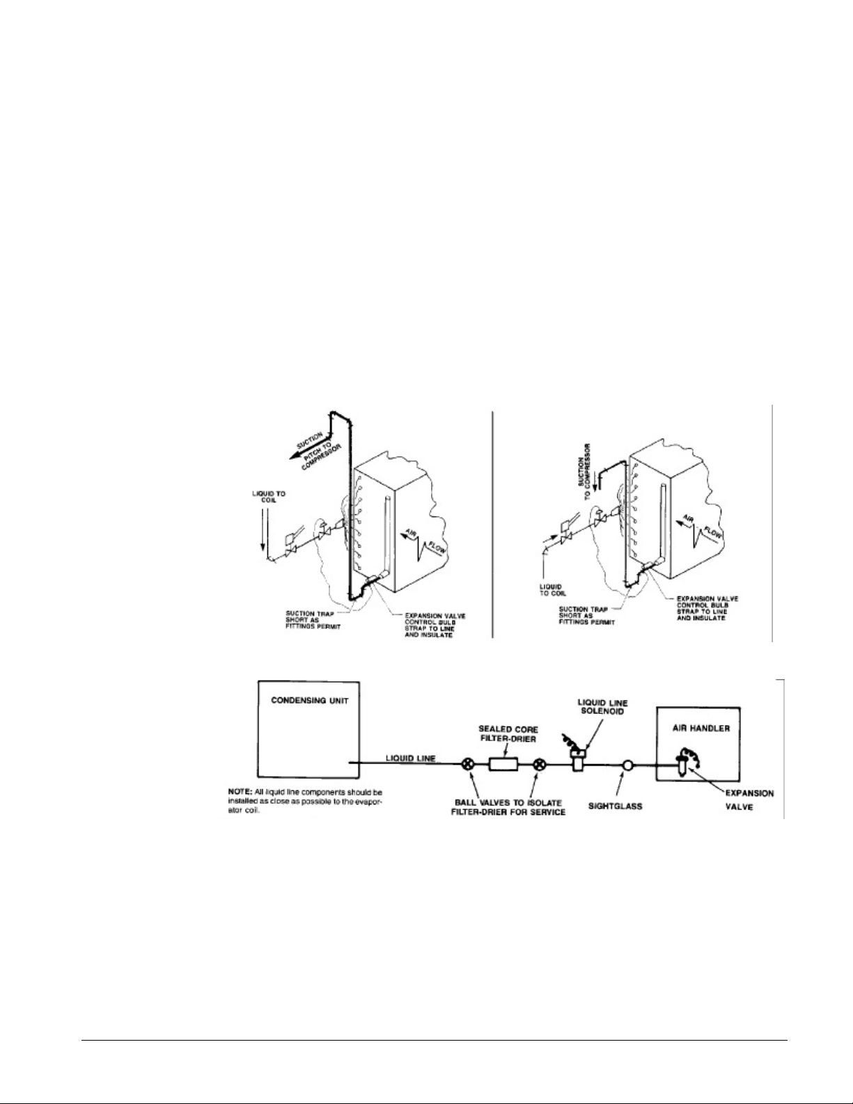
Figure 3, Single Circuit Evaporator—Recommended Piping
Figure 4, Recommended Liquid Line Piping
IM 687 ALP 012D through 019D 7
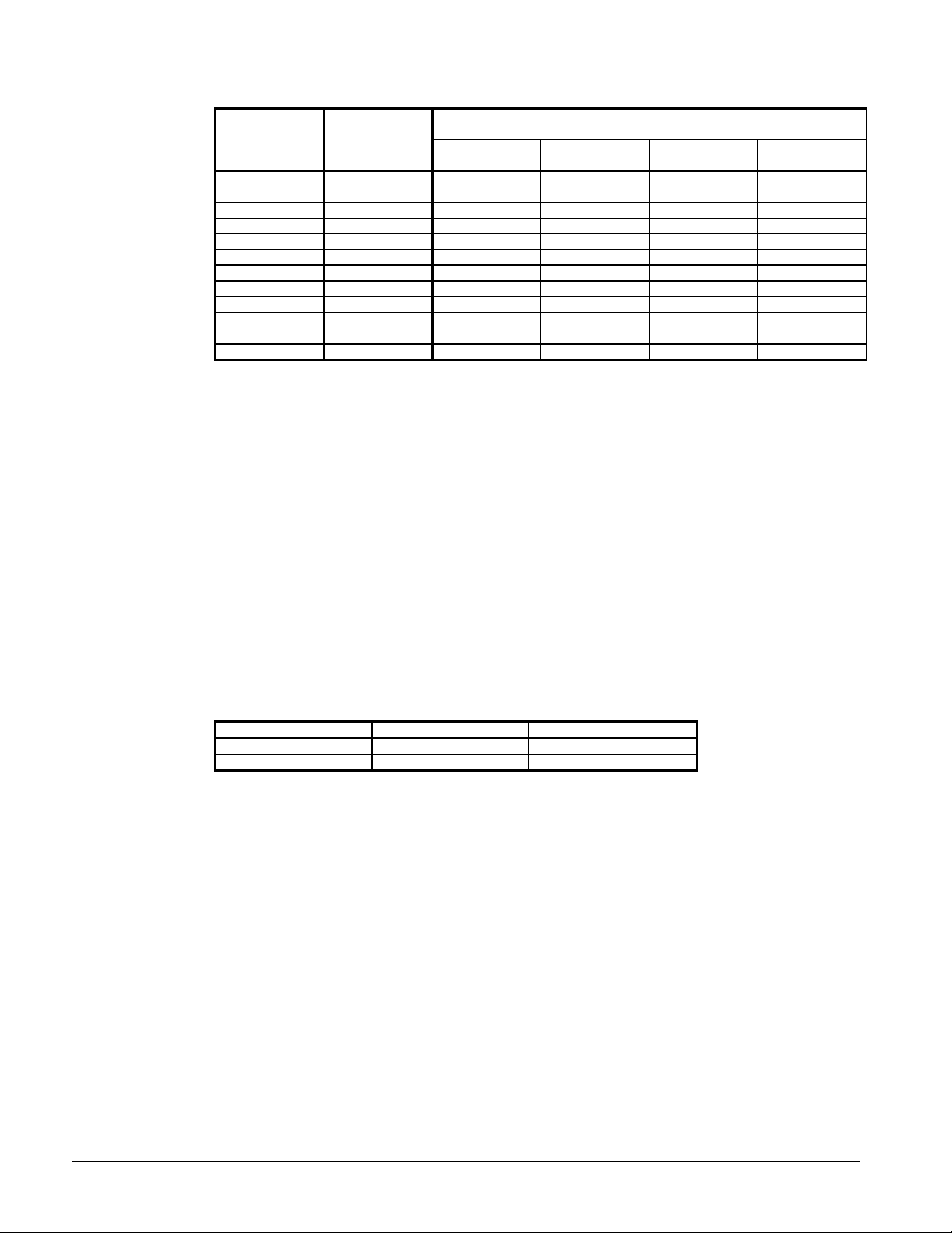
Table 4, Weight of R-22 in copper lines (Pounds Per 100 feet of type L tubing)
LINE SIZE
O.D.(in.)
3/8 0.054 3.84 0.202 0.052 0.077
1/2 0.100 7.12 0.374 0.096 0.143
5/8 0.162 11.5 0.605 0.156 0.232
7/8 0.336 24.0 1.26 0.323 0.480
1 1/8 0.573 40.8 2.14 0.550 0.820
1 3/8 0.872 62.1 3.26 0.839 1.25
1 5/8 1.237 88.0 4.62 1.19 1.77
2 1/8 2.147 153.0 8.04 2.06 3.06
2 5/8 3.312 236.0 12.4 3.18 4.72
3 1/8 4.728 336.0 17.7 4.55 6.75
3 5/8 6.398 456.0 24.0 6.15 9.14
4 1/8 8.313 592.0 31.1 8.00 11.19
VOL PER 100
FT (CU, FT)
LIQUID @
100°F
WEIGHT OF REFRIGERANT (LBS)
HOT GAS @
120°F
SUCTION GAS
@20°F
SUCTION GAS
@ 40°F
Liquid Line Components
Liquid line components should include:
1. Filter-drier
2. Refrigerant solenoid valve/115 volt coil
3. Refrigerant sightglass/moisture indicator
4. Expansion valve/R-22
5. Manual shutoff valve
All liquid line components are field supplied and should be selected and installed according to good
field piping practices, ASHRAE Guide, and individual component manufacturer recommendations.
Hot Gas Bypass Components
Hot gas bypass kits are available for each ALP unit size. Each kit includes a solenoid valve, a hot
gas bypass valve and instruction drawing. See page 8 for hot gas bypass operation.
Table 5, Hot Gas Bypass Kits
ALP UNIT SIZE KIT NUMBER LINE SIZE O.D. (IN.)
012D 550443A-03 5/8
015D & 019D 550443A-04 7/8
Refrigerant Piping Connections
Refrigerant piping connections will be made at the compressor end of the unit. Suction and liquid
lines should be routed through the compressor enclosure on the side of the unit.
Water Piping
The following section applies to remote mounted DX water chillers.
Local authorities can supply the installer with the proper building and safety codes required for safe
and proper installation.
Install piping with minimum bends and changes in elevation to minimize pressure drop.
Consider the following when installing water piping:
1. Vibration eliminators to reduce vibration and noise transmission to the building.
2. Shutoff valves to isolate the unit from the piping system during unit servicing.
3. Manual or automatic air vent valves at the high points of the system. Install drains at the
lowest points in the system.
4. A means of maintaining adequate system water pressure (expansion tank or regulating valve).
8 ALP 012D through 019D IM 687
5. Temperature and pressure indicators located at the unit to aid in unit servicing.
6. A strainer or other means of removing foreign matter from the water before it enters the pump.
Place the strainer far enough upstream to prevent cavitation at the pump inlet (consult pump
manufacturer for recommendations). The use of a strainer will prolong pump life and keep
system performance up.
7. Place a strainer in the water line just before the inlet of the evaporator. This will help prevent
foreign material from entering and decreasing the performance of the evaporator.
CAUTION
If separate disconnect is used for the 110V supply to the evaporator heating cable, mark
the disconnect clearly to ensure disconnect is not accidentally shut off during cold seasons.
8. The brazed plate evaporator has a thermostat and heating cable to prevent freeze-up down to 20°F (-29°C). It is suggested that the heating cable be wired to a separate 110V supply circuit.
As shipped from the factory, the heating cable is wired to the control circuit. All water piping
to the unit must also be protected to prevent freezing.
9. If the unit is used as a replacement chiller on a previously existing piping system, flush the
system thoroughly before unit installation. Regular water analysis and chemical water
treatment on the evaporator is recommended immediately at equipment start-up.
10. The total water volume in the system should be sufficient to prevent frequent “on-off” cycling.
Turnover rate should not be less than 15 minutes for normal variable cooling loads. Turnover
rate for process cooling or a constant load,should not be less than 6 minutes.
11. When glycol is added to the water system for freeze protection, the refrigerant suction pressure
will be lower, cooling performance less, and water side pressure drop greater. If the percentage
of glycol is high, or if propylene is used instead of ethylene glycol, the added pressure drop and
loss of performance could be substantial. Reset the freezestat and low leaving water alarm
temperatures. The freezestat is factory set to default at 36°F (2.2°C). Reset the freezestat
setting to approximately 4 to 5 degress F (2.3 to 2.8 degress C) below the leaving chilled water
setpoint temperature. See the section titled “Glycol Solutions” for additional information
concerning glycol.
12. Perform a preliminary leak check before insulating the piping and filling the system.
13. Piping insulation should include a vapor barrier to prevent condensation and possible damage
to the building structure.
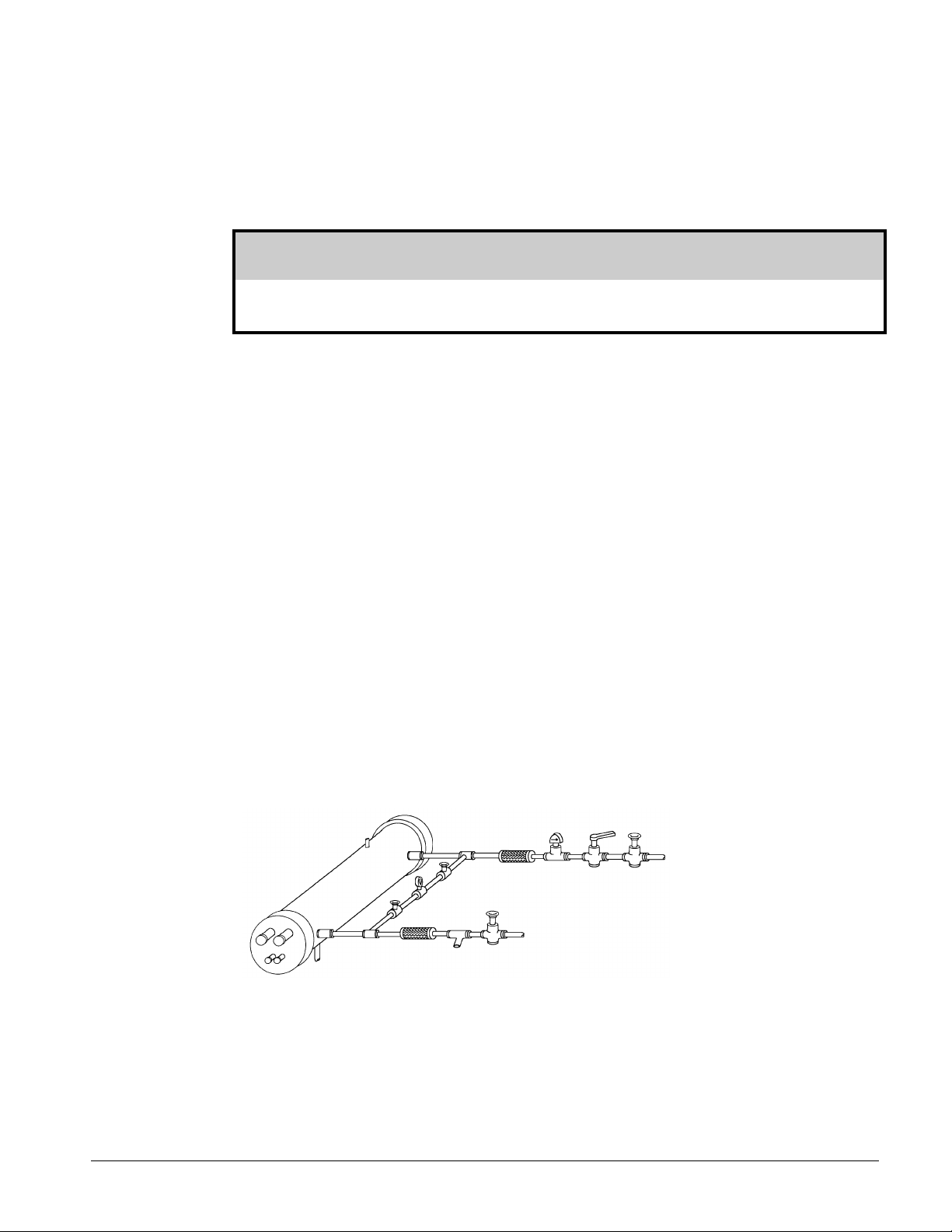
Figure 5, Typical field evaporator water piping
Vent
Outlet
Vibration
Drain
Vibration
Eliminator
Valved
pressure
gauge
Water
strainer
Eliminator
Gate valve
IM 687 ALP 012D through 019D 9
Flow
Balancing
Switch
Protect all field piping
against freezing
valve
Gate valve

Flow Switch
Mount a water flow switch in either the entering or leaving water line to shut down the unit when
water flow is interrupted.
A flow switch is available from McQuay (part number 0701804-04). It is a “paddle” type
switch and adaptable to pipe sizes down to 1 1/4 ” (32mm) nominal. Certain minimum flow rates
are required to close the switch and are listed in Table 6. Installation should be as shown in
Figure 6. Connect the normally open contacts of the flow switch in the unit control center at
terminals 4 and 5. There is also a set of normally closed contacts on the switch that can be used for
an indicator light or an alarm to indicate when a “no flow” condition exists. Freeze protect any flow
switch that is installed outdoors.
Table 6, Flow switch minimum flow rates
NOMINAL PIPE SIZE MINIMUM REQUIRED FLOW TO
INCHES (MM) ACTIVATE SWITCH - GPM (L/S)
1 (25.4) 6.00 (0.38)
11/4 (31.8) 9.80 (0.62)
11/2 (38.1) 12.70 (0.80)
2 (50.8) 18.80 (1.20)
21/2 (63.50 24.30 (1.50)
3 (76.20 30.00 (1.90)
Figure 6, Flow switch installation
Flow direction
marked on switch
5" (127mm) pipe
dia. Min. after
1" (25mm) NPT
flow switch
Tee
5" (127mm) pipe
dia. Min. before
10 ALP 012D through 019D IM 687

Initial Start-up
Holding Charge
The condensing unit is shipped with a holding charge of refrigerant. Perform a pressure check of
the unit. If no pressure is evident, leak test the unit and repair leak. This should be noted and
reported to your sales representative or freight carrier if the loss is due to shipping damage.
Leak Testing
When the refrigerant holding charge is lost, check for leaks before charging the complete system.
Leak testing can be done by charging the refrigerant into the unit to build the pressure to
approximately 10 psig and adding sufficient dry nitrogen to bring the pressure to a maximum of 125
psig. Leak test with a Halide or electronic leak detector. After making any necessary repair,
evacuate the system.
Do not use oxygen to build up pressure. A serious explosion could be the result.
WARNING
Evacuation
Use a vacuum pump with a pumping capacity of approximately 3 cu. ft./min. and the ability to
reduce the vacuum in the unit to at least 1 millimeter (1000 microns).
1. Connect a mercury manometer, electronic or other type of micron gauge to the unit at a point
remote from the vacuum pump. For readings below 1 millimeter, an electronic or other micron
gauge should be used.
2. If the vacuum pump is unable to obtain the desired 1 millimeter of vacuum, evacuate the system
to about 29 inches of mercury. Add enough refrigerant vapor to the system to bring the pressure
up to 0 pounds.
3. Evacuate the system to 29 inches of vacuum. Repeat three times. This method can be most
effective by holding system pressure at 0 pounds for a minimum of 1 hour between evacuations.
The first pull down will remove about 90% of the noncondensables, the second about 90% of
that remaining from the first pull down and after the third only 1/10 of 1% noncondensables
will remain.
Charging The System
After all refrigerant piping is complete and the system has been evacuated, charge the unit as
follows:
1. Connect refrigerant drum to gauge port on liquid line and purge the charging line between the
refrigerant cylinder and the valve. Open the valve to mid-position.
2. If the system is under a vacuum, stand refrigerant drum with connection up and open drum and
break the vacuum with refrigerant gas.
3. With a system gas pressure higher than the equivalent of a freezing temperature, invert the
charging cylinder and elevate the drum above the condenser. With the drum in this position,
valves open and liquid refrigerant will flow into the condenser. Approximately 75% of the total
requirement estimated for the unit can be charged in this manner.
4. After 75% of the required charge has entered the condenser, reconnect the refrigerant drum and
charging line to the suction side of the system. Purge the connecting line, stand the drum with
the connection up, and place service valve in open position.
IM 687 ALP 012D through 019D 11

Important: At this point charging procedure should be interrupted and prestart checks
made before attempting to complete the refrigerant charge, (see startup procedures).
Note: It is recommended that the total operating charge per circuit be stamped on the unit
nameplate for future reference.
Refrigerant Charge
Each ALP condensing unit is designed for use with R-22. See Physical Data for approximate
refrigeration charges for operation of the unit. Additional refrigerant will be needed for the system
piping and evaporator. Estimated total operating charge should be calculated before charging
system.
CAUTION
Total operating charge per circuit should not exceed the condenser pumpdown capacity per
circuit plus the capacity of the liquid line. A liquid receiver on each refrigerant circuit
should be used if the unit operating charge exceeds the pumpdown capacity. Refer to the
ASHRAE Handbook for the design and installation of piping and components.
Pre-Startup
1. With electric disconnects open, check all screw or lug type electrical connections to be sure they
are tight. Check all compressor valve connections for tightness to avoid refrigerant loss at
startup. Although all factory connections are tight before shipment, some loosening may have
resulted from shipping vibration.
2. Check the voltage of the unit power supply and verify it is within 10% of the nameplate rating.
Phase voltage unbalance must be within 2%.
3. Check the unit power supply wiring for adequate ampacity and a minimum insulation
temperature rating of 75°C.
4. Verify all mechanical and electrical inspections have been completed according to local codes.
5. Verify all auxiliary control equipment is operative and that an adequate cooling load is available
for initial startup.
6. Adjust the dial on the temperature controller to well below desired set point to prevent unit
operation. Leave the unit disconnect on and allow the crankcase heater to operate at least 8
hours before start-up.
WARNING
Most relays and terminals in the unit control center are energized with the unit
disconnect on.
12 ALP 012D through 019D IM 687

Startup
1. Start the auxiliary equipment for the installation.
2. Adjust the dial on the temperature controller to the desired leaving air temperature.
3. After running the unit for a short period of time, check for proper rotation of the condenser fans
and check for refrigerant flashing in the sightglass.
4. Adjust superheat to maintain between 10°F and 12°F at the evaporator.
5. Adjust subcooling to maintain between 8°F to 12°F.
6. After system performance has been stabilized, Complete the “Compressorized Equipment
Warranty Registration Form” (Form No. 550488A-01) to obtain full warranty benefits. Consult
the Product Warranty Certificate for details. Both forms are supplied with the units where
required.
IM 687 ALP 012D through 019D 13

Dimensional Data
Figure 7. ALP-012D
14 ALP 012D through 019D IM 687

Figure 8, ALP 015 and 019
IM 687 ALP 012D through 019D 15

Physical Data
Table 7, ALP Physical Data
DATA ALP MODEL NUMBER
012D 015D 019D
BASIC DATA
Unit Capacity @ ARI Conditions, Mbh (kW)(1) 155 (39) 183 (54) 236 (69)
Number Of Refrigerant Circuits 1 1 1
Unit Holding Charge, R-22, Lbs. (kg) 11.0 (5.0) 11.0 (5.0) 12.0 (5.4)
Cabinet Dimensions, LxWxH, In. 78x36x36 78x40x36 78x40x36
Cabinet Dimensions, LxWxH, mm (1981x914x914) (1981x1016x914) (1981x1016x914)
Unit Shipping Weight, Lbs. (kg) 625 (284) 858 (389) 873 (396)
Add'l Weight If Ccopper Finned Coils, Lbs. (kg) 210 (95) 210 (95) 220 (100)
COMPRESSORS
Type Scroll Scroll Scroll
Nominal Horsepower 6.0 / 6.0 7.5 / 7.5 9.0 / 9.0
Oil Charge Per Compressor, Oz. (g) 60 (1866) 140 (4354) 140 (4354)
CAPACITY REDUCTION STEPS - % OF COMPRESSOR DISPLACEMENT
Standard taging 0-50-100 0-50-100 0-50-100
Optional SStaging N/A N/A N/A
CONDENSERS - HIGH EFF. FIN & TUBE TYPE WITH INTEGRAL SUBCOOLING
Coil Face Area,Sq. Ft. (M2) 30.3 (2.8) 30.3 (2.8) 30.3 (2.8)
Finned Height x Finned Length, In. 66 x 66 66 x 66 66 x 66
Finned Height x Finned Length, mm (1676x1676) (1676x1676) (1676x1676)
Fins Per Inch x Rows Deep 16 x 2 16 x 2 16 x 3
CONDENSER FANS - DIRECT DRIVE PROPELLER TYPE
Number Of Fans - Fan Diameter, In. (mm) 2 - 24 (610) 2 - 24 (610) 2 - 24 (610)
Number Of Motors - HP (kW) 2 - .5 (.4) 2 - .5 (.4) 2 - .5 (.4)
Fan And Motor RPM, 60/50Hz 1075/896 1075/896 1075/896
60 Hz Fan Tip Speed, FPM 6750 6750 6750
50 Hz Fan Tip Speed, M/sec 28.6 28.6 28.6
60 Hz Total Unit Airflow, CFM 10150 10150 9800
50 Hz Total Unit Airflow, M3/sec 4.0 4.0 3.9
Notes:
1. Nominal capacity based on 95°F ambient air and 45°F suction.
2. Total pumpdown capacity will be unit pumpdown capacity plus liquid line capacity.
3. “Unit operating charge” does NOT include any estimate of the refrigerant quantity required for the evaporator and interconnecting piping.
4. Some oil may need to be added to satisfy the requirements of the finished refrigerant system due to the miscibility of the refrigerant and oil. If oil must
be added, it should be of the same type and grade recommended by the compressor manufacturer. Care must be taken to prevent adding excessive
oil since equipment damage including compressor failure may result. Contact the McQuay Service technical group in Staunton for additional
information if necessary.
16 ALP 012D through 019D IM 687

Electrical Data
Table 8, Electrical data single point
012D 460 60 25 3 10 1 0.50 (13) 30 30
015D 460 60 33 3 8 1 0.75 (19) 40 40
019D 460 60 39 3 8 1 0.75 (19) 45 50
Minimum POWER SUPPLY FIELD FUSE SIZE
ALP Circuit Field Wire Hub
Unit Volts HZ. Ampacity Wire Nominal Recommended Maximum
Size (MCA) Quantity Gauge Quantity Size
208 51 3 6 1 1.00 (25) 60 60
230 51 3 6 1 1.00 (25) 60 60
575 20 3 10 1 0.50 (13) 25 25
415 50 25 3 10 1 0.50 (13) 30 30
380 25 3 10 1 0.50 (13) 30 30
208 60 3 6 1 1.00 (25) 70 80
230 60 3 6 1 1.00 (25) 70 80
575 24 3 10 1 0.50 (13) 30 30
415 50 30 3 8 1 0.75 (19) 40 40
380 30 3 8 1 0.75 (19) 40 40
208 76 3 4 1 1.00 (25) 90 100
230 76 3 4 1 1.00 (25) 90 100
575 30 3 10 1 0.50 (13) 35 40
415 50 37 3 8 1 0.75 (19) 45 50
380 37 3 8 1 0.75 (19) 45 50
Table 9, Compressor and condenser fan motor amp draw
Rated Load Amps Locked Rotor Amps
Compressors Fan No. Of Fan Compressors
Volts HZ. No. No. No. No. Motors Fan Motors Across-The-Line Reduced Inrush
1 2 3 4 (Each) Motors (Each) No. 1 No. 2 No. 3 No. 4 No. 1 No. 2 No. 3 No. 4
ALP 208 18.6 18.6 ---- ---- 4.2 2 8.8 156 156 ---- ---- N/A N/A ---- ----
Unit 230 18.6 18.6 ---- ---- 4.2 2 8.8 156 156 ---- ---- N/A N/A ---- ----
012D 460 60 9 9 ---- ---- 2.1 2 4.8 70 70 ---- ---- N/A N/A ---- ----
575 7.4 7.4 ---- ---- 1.6 2 3.7 54 54 ---- ---- N/A N/A ---- ---415 50 9 9 ---- ---- 2.1 2 4.8 74 74 ---- ---- N/A N/A ---- ---380 9 9 ---- ---- 2.1 2 4.8 67 67 ---- ---- N/A N/A ---- ---208 22.9 22.9 ---- ---- 4.2 2 8.8 189 189 ---- ---- N/A N/A ---- ---230 22.9 22.9 ---- ---- 4.2 2 8.8 189 189 ---- ---- N/A N/A ---- ----
015D 460 60 12.5 12.5 ---- ---- 2.1 2 4.8 94 94 ---- ---- N/A N/A ---- ----
575 9.1 9.1 ---- ---- 1.6 2 3.7 74 74 ---- ---- N/A N/A ---- ---415 50 11.3 11.3 ---- ---- 2.1 2 4.8 99 99 ---- ---- N/A N/A ---- ---380 11.3 11.3 ---- ---- 2.1 2 4.8 89 89 ---- ---- N/A N/A ---- ---208 29.9 29.9 ---- ---- 4.2 2 8.8 232 232 ---- ---- N/A N/A ---- ---230 29.9 29.9 ---- ---- 4.2 2 8.8 232 232 ---- ---- N/A N/A ---- ----
019D 460 60 15.3 15.3 ---- ---- 2.1 2 4.8 116 116 ---- ---- N/A N/A ---- ----
575 11.5 11.5 ---- ---- 1.6 2 3.7 97 97 ---- ---- N/A N/A ---- ---415 50 14.4 14.4 ---- ---- 2.1 2 4.8 123 123 ---- ---- N/A N/A ---- ---380 14.4 14.4 ---- ---- 2.1 2 4.8 110 110 ---- ---- N/A N/A ---- ----
IM 687 ALP 012D through 019D 17

Table 10, Field wiring data
Wiring to
ALP Standard Power Block
Unit Volts HZ. Terminal Connector Wire Range
Size Amps (Copper Wire Only)
208 175 (1 qty.) #12 - 2/0
230 175 (1 qty.) #12 - 2/0
012D 460 60 175 (1 qty.) #12 - 2/0
575 175 (1 qty.) #12 - 2/0
415 50 175 (1 qty.) #12 - 2/0
380 175 (1 qty.) #12 - 2/0
208 175 (1 qty.) #12 - 2/0
230 175 (1 qty.) #12 - 2/0
015D 460 60 175 (1 qty.) #12 - 2/0
575 175 (1 qty.) #12 - 2/0
415 50 175 (1 qty.) #12 - 2/0
380 175 (1 qty.) #12 - 2/0
208 175 (1 qty.) #12 - 2/0
230 175 (1 qty.) #12 - 2/0
019D 460 60 175 (1 qty.) #12 - 2/0
575 175 (1 qty.) #12 - 2/0
415 50 175 (1 qty.) #12 - 2/0
380 175 (1 qty.) #12 - 2/0
Notes:
1. Voltage must be within 10% of nameplate rating
2. Unit wire size amps are equal to 125% of the compressor branch circuit selection current plus 100% of RLA of all other
loads in the circuit including control transformer.
3. RLA of 2 speed compressors running on low speed will be 50% of Table 11 RLA value.
4. Each ALP unit is provided with 7/8” dia. knockouts to be used as a pilot for making larger power entry hubs.
18 ALP 012D through 019D IM 687

Field Wiring
CAUTION
Use only copper conductors in main terminal block
Wiring must be in accordance with all applicable codes and ordinances. Warranty is void if wiring
is not in accordance with specifications. An open fuse indicates a short, ground or overload. Before
replacing a fuse or restarting a compressor or fan motor, find and correct the trouble.
Figure 7 shows typical field wiring required for unit installation. Items that require field wiring are
liquid line solenoid SV1, cooling thermostat, and unit power supplies.
Note: See dimensional data for knockout locations.
IM 687 ALP 012D through 019D 19

Figure 9, Typical Field Wiring
20 ALP 012D through 019D IM 687

Electrical Legend
DESIGNATION DESCRIPTION STD. LOCATION
AB ALARM BELL FIELD MOUNTED
C11, C12 CAPACITORS FOR FAN MOTORS BACK OF CONTROL BOX
COMPR.1 COMPRESSOR BASE OF UNIT
F1 FUSE, CONTROL CIRCUIT CONTROL BOX
FB5 FUSE BLOCK, CONTROL POWER CONTROL BOX
FB6 FUSE BLOCK, FAN MOTORS CONTROL BOX
GRD GROUND CONTROL BOX
HP1,2 HIGH PRESSURE CONTROL ON COMPRESSOR
HTR HEATER, COMPRESSOR CRANKCASE ON COMPRESSOR
LP1 LOW PRESSURE CONTROL ON COMPRESSOR
M1-9 CONTRACTORS, COMPRESSOR CONTROL BOX
M11-12 CONTRACTORS, FAN MOTORS CONTROL BOX
MJ MECHANICAL JUMPERS CONTROL BOX
MP1-4 MOTOR PROTECTOR COMPRESSOR COMPRESSOR JUNCTION BOX
MTR11 MOTORS, CONDENSER FANS CONDENSER SECTION
NB NEUTRAL BLOCK CONTROL BOX
PB1 POWER BLOCK, MAIN CONTROL BOX
PC12 PRESSURE CONTROL, (FANTROL) CONTROL BOX
DESIGNATION DESCRIPTION STD. LOCATION
R13 RELAYS, LOW AMBIENT START CONTROL BOX
R3,4 RELAYS CAPACITY CONTROL CONTROL BOX
SC11 SPEED CONTROLS ON BULKHEAD
T1 TRANSFORMER, MAIN CONTROL CONTROL BOX
T2 TRANSFORMER, 24V CONTROL CONTROL BOX
TB2 TERMINAL BLOCK, 120V, FIELD CONTROL BOX
TB3 TERMINAL BLOCK, 24V, FIELD CONTROL BOX
TB4-6 TERMINAL BLOCKS, CONTROL CONTROL BOX
TD4-6 TERMINAL BLOCKS, CONTROL CONTROL BOX
TD1-2 TIME DELAYS, COMPRESSOR LOCKOUT CONTROL BOX
TD9 TIME DELAYS, LOW AMBIENT CONTROL BOX
IM 687 ALP 012D through 019D 21

Normal Sequence Of Operation
The following sequence of operation is typical. The sequence varies somewhat depending upon
options.
Startup
With power to the unit and the control stop switch S1 closed, 115V power is applied to the control
circuit. If there is no call for cooling the crankcase heaters HTR1 and HTR2 will be energized and
operating. Power will also be supplied to the 24V transformer providing power for the thermostat,
the compressor motor protector, and compressor lockout time delay TD1. The unit will
automatically operate in response to the thermostat provided the compressor lockout time delay TD1
has closed, energizing safety relay R5, and the high pressure control HP1 and motor protector MP1
do not sense failure conditions.
On call for the first stage of cooling relay R3 is energized which will energize the liquid line
solenoid valve SV1. This allows refrigerant to flow through the thermostatic expansion valve and
into the evaporator. As the refrigerant pressure in the evaporator increases, the low pressure control
LP1 closes. Power will now be fed to the compressor contactor M1, starting the first compressor.
Power will also be fed to the condenser fan motor contactors M11 and M12.
On a call for the second stage of cooling TD2 will energize relay R4. R4 will energize M2,
starting the second compressor.. TD2 will time out for 5 minutes with initial power applied.
Pumpdown
As the unit’s thermostat is satisfied, it will de-energize the liquid line solenoid valve SV1 causing
the valve to close. When the compressor has pumped most of the refrigerant out of the evaporator
and into the condenser, the low pressure control LP1 will open, shutting down the compressor and
condenser fan motors. The compressor will now be unable to start for 5 minutes via the compressor
lockout time delay TD1.
If refrigerant leaks into the evaporator, the increase in pressure will cause the low pressure
switch LP1 to close. This will energize the compressor contactor M1 starting the compressor which
will quickly pump the refrigerant out of the evaporator and into the condenser (recycling
pumpdown).
A compressor which recycles pumpdown every 5 minutes indicates a malfunction. Corrective
measures must be taken if the compressor recycles repeatedly within 15-minute intervals.
22 ALP 012D through 019D IM 687

System Maintenance
General
On initial startup and periodically during operation, it will be necessary to perform certain routine
service checks. Among these are taking condensing and suction pressures. On units ordered with
gauges, condensing and suction pressures can be read from the vertical support on the side of the
unit adjacent to the compressors.
The gauges are factory installed with a manual shutoff valve on each gauge line. The valves
should be closed at all times except when gauge readings are being taken.
Fan Motor Bearings
The fan motor bearings are of the permanently lubricated type. No lubrication is required.
Electrical Terminals
Electric shock hazard. Turn off all power before continuing with following service.
WARNING
Retighten all power electrical terminals every six months.
Condensers
WARNING
Cleaners may contain potentially harmful chemicals.
Condensers are air-cooled and constructed with 3/8” O.D. internally finned copper tubes bonded in
a staggered pattern into slit aluminum fins. No maintenance is ordinarily required except the
occasional removal of dirt and debris from the outside surface of the fins. Use locally purchased
foaming condenser coil cleaners for periodic cleaning of the coil. Do not damage the fins during
cleaning.
Refrigerant Sightglass
Visually check refrigerant sightglass at least once a month A clear glass of liquid indicates there is
adequate refrigerant charge in the system to ensure proper feed through the expansion valve.
Bubbling refrigerant in the sightglass indicates the system is short of refrigerant charge. Refrigerant
gas flashing in the sightglass could also indicate an excessive pressure drop in the line, possible due
to a clogged filter-drier or a restriction elsewhere in the system.. If the sightglass does not indicate a
dry condition after about 12 hours of operation, the unit should be pumped down and the filterdriers changed.
IM 687 ALP 012D through 019D 23

Service
Note: Service on this equipment is to be performed by qualified service personnel. Causes
for repeated tripping of safety controls must be investigated and corrected.
WARNING
Disconnect all power before doing any service inside the unit.
Thermostat Expansion Valve
The expansion valve allows the proper amount of refrigerant to enter the evaporator (regardless of
cooling load) by maintaining a constant superheat. (Superheat is the difference between refrigerant
temperature as it leaves the evaporator and the saturation temperature corresponding to the
evaporator pressure.) Typically, superheat should run in the range of 10°F to 15°F.
Adjust the superheat setting as follows:
1. Remove cap at the bottom of valve to expose adjustment screw.
2. Turn screw clockwise (when viewed from the adjustment screw end) to increase the superheat
setting and counterclockwise to reduce superheat. Allow time for system rebalance after each
superheat adjustment.
The expansion valve, like the solenoid valve, should not normally require replacement, but if it does
the unit must be pumped down by following the steps involved when changing a filter-drier.
If the problem can be traced to the power element only, it can be unscrewed from the valve body
without removing the valve, but only after pumping the unit down.
Filter-Driers
To change the liquid line filter-drier,
1. Close the field supplied manual liquid line shutoff valve.
2. Jump out the low pressure control and allow the unit to pump down to 0-5 PSIG.
3. When the evaporator pressure reaches 0-5 PSIG, shut the unit off at the disconnect.
After the filter-drier has been changed, purge some refrigerant through the line to remove
noncondensables that may have entered during filter replacement. A leak check is recommended
before returning unit to operation.
Liquid Line Solenoid
The liquid line solenoid valve does not normally require any maintenance. The solenoid coil may
require replacement. To remove solenoid coil from valve body (without opening the system):
1. Disconnect power to the unit.
2. Remove the nut or snap ring located at the top of coil.
3. Remove coil from valve body.
24 ALP 012D through 019D IM 687

Standard Controls
Note: Perform an operational check on all unit safety controls once per year.
High Pressure Control
The high pressure control is a single pole pressure activated switch that closes on a rise in pressure.
When the switch closes, it de-energizes the compressor circuit preventing unit operation until the
high pressure control is reset. The control is factory set to close at 400 PSIG and reset at 300 PSIG.
The control is attached to a Shrader fitting on the discharge line located in the compressor
compartment.
Although there is an additional pressure relief device in the system set at 450 PSIG , it is
highly recommended that the control stop switch S1 be near at hand in case the high
pressure control should malfunction.
To check the control:
1. Block off the condenser surface --OR-- start the unit with condenser fan motors off.
2. Observe the cutout point of the control on the high side of the system.
3. Reset by opening and closing control stop switch S1.
4. Check pressure relief device for leaks.
CAUTION
Low Pressure Control
The low pressure control is a single pole pressure switch that closes on a pressure rise. It senses
evaporator pressure and is factory set to close at 60 PSI and automatically opens at 35 PSIG. To
check the low pressure control:
1. Make certain unit is running.
2. Remove wire #215 from terminal #28 (De-energizes R-3 relay which in turn will de-energize
the liquid line solenoid.)
3. As the compressor pumps down, condenser pressure will rise and evaporator pressure will drop.
The lowest evaporator pressure reached before cut-out is the cut-out setting of the control.
4. Wait five minutes.
5. Reconnect wire #215 to terminal #28. (Energizes the liquid line solenoid allowing evaporator
pressure to rise.) The highest evaporator pressure reached before compressor restart is the cutin setting of the control.
Compressor Lockout
Compressor lockout consists of a 5-minute time delay TD1. It is wired in series with the R5 safety
relay that energizes after 5 minutes, enabling the compressor to start. Its purpose is to prevent rapid
compressor cycling when cooling demands are erratic.
When the unit thermostat no longer calls for cooling and the compressor contactors have
opened, the lockout time delay breaks open the circuit, preventing compressor restart.
The circuit remains open for a period of 5 minutes. If unit thermostat should call for cooling
before the delay period has expired, the compressor will not restart. After 5 minutes the time delay
will close its contacts to complete the circuit to R5, enabling the compressor to start. When R9 is
IM 687 ALP 012D through 019D 25

energized with the compressor, another set of contacts will shunt around TD1, allowing TD1 to reset
open for timing out the next compressor cycle.
To check the time delay,
1. Make certain the compressor is running.
2. Adjust the temperature control to simulate no call for cooling. (Allows the unit to pump down)
3. Immediately after the compressor has stopped running adjust the temperature control to call for
cooling. The compressor should not restart for 5 minutes.
Compressor Motor Protector
The solid-state compressor motor protector module incorporates a 2-minute “time off” relay
utilizing the bleed down capacitor principle. Any time the protection system opens or power to the
module is interrupted, the 2-minute “time off” delay is triggered and the module will not reset for
two minutes. Once the 2-minute period has passed the motor protector contacts M1 and M2 reset,
provided the protection system is satisfied and power is applied to the module.
Note: If the power circuit is broken once the 2-minute period is passed the pilot circuit will
reset without delay when power is reapplied.
Fantrol Head Pressure Control
FanTrol is a method of head pressure control which automatically cycles condenser fan motor M12
in response to condenser pressure. This maintains head pressure and allows the unit to run at low
ambient air temperatures.
All ALP units have FanTrol which is a nonadjustable control set to open at 150 PSIG and close
at 225 PSIG. The control is attached to a Shrader fitting on the discharge line inside the compressor
compartment.
CAUTION
SpeedTrol and FanTrol will provide reasonable operating refrigerant discharge pressures to
the ambient temperatures listed for them PROVIDED THE COIL IS NOT AFFECTED BY
THE EXISTENCE OF WIND. If wind may occur and the unit includes vertical condenser
coils, it is the responsibility of the system designer or installer to make other provisions for
low ambient control. Consideration should be given to deflecting awnings, dampers, or a
floodback receiver system as required to satisfy specific job conditions.
Table 11, Fan Control Minimum Ambient Operation
ALP UNIT SIZE FANTROL (STANDARD FANTROL WITH LOW
012D
015D
019D
60°F 45°F 0°F
55°F 30°F 0°F
45°F 10°F 0°F
AMBIENT
SPEEDTROL
26 ALP 012D through 019D IM 687

Optional Controls
Speedtrol Head Pressure Control
The SpeedTrol method of head pressure control operates in conjunction with FanTrol by modulating
the motor speed on fan M11 in response to condenser pressure. By reducing the speed of the last fan
as the condensing pressure falls, the unit can operate at lower ambient temperatures.
The SpeedTrol fan motor is a single phase, 230/460 volt, thermally protected motor specially
designed for variable speed operation. The solid-state speed control SC11 is mounted in the unit
control panel and is connected to a Schrader fitting on the liquid line. The control is factory set to
start modulating fan speed at 230 PSIG, and will maintain a minimum condensing pressure of 170
to 180 PSIG. Minimum starting voltage for SpeedTrol motors is 120 volts.
Low Ambient Start
Low ambient start is available on all units as an option with FanTrol and included automatically
with optional SpeedTrol. It consists of a solid-state, normally closed time delay wired in series with
a relay. These are both wired in parallel to the liquid line solenoid valve. When the solenoid valve
is energized by the unit thermostat the low ambient start relay is also energized through the time
delay. The relay has contacts that essentially short-circuit the low pressure control and allow the
compressor to start with the low pressure control open.
After about 2-3/4 minutes, the time delay will open and de-energize the relay. If the system has
not built up enough evaporator pressure to close the low pressure control, the compressor will stop.
The time delay can be reset to its original normally closed position by de-energizing relay R3 in the
thermostat circuit.
Due to the vertical condenser design, it is recommended that the unit be oriented so prevailing
winds blow parallel to the unit length, minimizing effects on minimum ambient operation. If it is
not practical to orient the unit in this manner, a wind deflector should be constructed.
Figure 10, Low ambient start time delay/relay R13
Hot Gas Bypass
Hot gas bypass is a system for maintaining evaporator pressure at or above a minimum value. This
keeps the velocity of the refrigerant as it passes through the evaporator high enough for proper oil
return to the compressor when cooling load conditions are light. It also maintains continuous
operation of the chiller at light load conditions.
Wire the hot gas solenoid (SV5) in parallel with the liquid line solenoid at terminals 14 and 15.
(Solenoid valve will open whenever the liquid line solenoid valve is energized.) The pressure
regulating valve is factory set to begin opening at 58 PSIG (32°F for R-22) when the air charged
bulb is in an 80°F ambient temperature. The bulb can be mounted anywhere as long as it senses a
fairly constant temperature at various load conditions. The compressor suction line is a good
mounting location. It is generally in the 50°F to 60°F range.
IM 687 ALP 012D through 019D 27

The chart below indicates that when the bulb is sensing 50°F to 60°F temperatures, the valve will
begin opening around 54 PSIG. This setting can be changed. To raise the pressure setting, remove
the cap on the bulb and turn the adjustment screw clockwise. To lower the setting, turn the screw
counterclockwise. Do not force the adjustment beyond the range it is designed for, as this will
damage the adjustment assembly.
WARNING
The hot gas line may become hot enough to cause injury in a very short time.
Be careful during valve checkout.
The regulating valve opening point can be determined by slowly reducing the system load (or
increasing the required chiller water temperature setting indicated on the unit thermostat), while
observing the suction pressure. When the bypass valve starts to open, the refrigerant line on the
evaporator side of the valve will begin to feel warm to the touch.
When the condensing unit is remote from the evaporator, mount the hot gas bypass valve near
the condensing unit to minimize the amount of refrigerant that will condense in the hot gas line
during periods when hot gas bypass is not required.
Figure 11, Hot Gas Bypass Piping Figure 12, Hot Gas Bypass Adjustment
Table 12, ALP CONTROLS, SETTINGS AND FUNCTIONS
DESCRIPTION FUNCTION SYMBOL SETTING RESET LCATION DIFFERENTIAL
HIGH PRESSURE
CONTROL
LOW PRESSURE
CONTROL
MOTOR
PROTECTOR
FANTROL
CONTROL
SPEEDTROL
CONTROL
LIQUID LINE
SOLENOID
HGBP SOLENOID
VALVE
LOCKOUT TIME
DELAY
LOW AMBIENT
START DELAY
HIGH PRESSURE
SPEED CONTROL
28 ALP 012D through 019D IM 687
Stops compressor at
high discharge
Stops compressor at
low suction
High motor
temperature
Cycles fans by
condensing pressure
Modulates fan speed
by condensing press.
Close liquid line for
pumpdown
Close HGBP for
pumpdown
Prevents
compressor short
cycling
Bypass LP control
for cold starts
HP1 Closes at 400 PSIG
Opens at 300 PSIG
LP1 Closes at 60 PSIG
Opens at 35 PSIG
MP1 500 ohms cold to
20,000 ohms hot
PC12 See Fantrol
description
SC11 Maintains min. of
170 to 180 PSIG
SV1 N/A N/A Field
SV5 N/A N/A Condenser
TD1 Fixed 5 minutes Auto Control box N/A
TD9 2 3/4 minutes Auto Control box N/A
Manual thruS1Discharge
Auto Suction line 25 PSIG fixed
Auto 2700 to
4500 ohms
Auto Discharge
Auto Liquid line N/A
line
Compressor
junction box
line
installed
section
100 PSIG fixed
15,000 ohms
120 PSIG fixed
N/A
N/A

Troubleshooting Chart
PROBLEM POSSIBLE CAUSES POSSIBLE CORRECTIVE STEPS
COMPRESSOR
WILL NOT RUN
1. Main switch open
2. Fuse blown, breakers open
3. Thermal overloads tripped
4. Defective contactor or coil
5. System of by safety device
6. No cooling required
7. Liquid line solenoid will not open
8. Motor electrical problem
9. Loose wiring
1. Close switch
2. Check electrical circuits and motor windings for
shorts. Check for overloads and loose connections.
Replace fuse or reset breaker.
3. Check unit when back on line, auto reset
4. Repair or replace
5. Determine cause and correct
6. None, should start on call for cooling
7. Repair or replace coil
8. Check motor for open or short circiut, or burnout
9. Check all wire junction. Tighten all terminals.
COMPRESSOR
NOISY OR
VIBRATING
HIGH DISCHARGE
PRESSURE
LOW DISCHARGE
PRESSURE
HIGH SUCTION
PRESSURE
LOW SUCTION
PRESSURE
MOTOR
OVERLOAD
RELAYS OPEN OR
BLOWN FUSES
COMPRESSOR
THERMAL SWITCH
OPEN
1. Refrigerant flooding compressor
2. Improper line support
3. Worn compressor
1. Noncondensables in system
2. Refrigerant overcharge
3. Discharge valve partially closed
4. Fan not running
5. Dirty condenser coils
6. FanTrol out of adjustment
1. Faulty condenser control
2. Low refrigerant charge
3. Low suction pressure
1. Excessive load
2. Expansion valve overfeeding
1. Lack of refrigerant
2. Evaporator dirty
3. Clogged filter-drier
4. Clogged suction strainer
5. Expansion valve malfunctioning
6. Low condensing temperature
7. Compressor will not load
8. Low evaporator air flow
1. Low voltage during high loads
2. Defective or grounded motor wiring
3. Loose power wiring
4. High condensing temperature
5. Unbalanced voltage
6. High ambient at overload relay
1. Operating beyond design conditions 1. Add facilities so conditions are within allowable
1. Chect expansion valve setting
2. Relocate or add supports
3. Replace
1. Remove with authoriized procedures
2. Remove excess
3. Open valve
4. Check electrical circuit
5. Clean coil
6. Adjust FanTrol settingd
1. Check condenser control operation
2. Check for leaks. Add refrigerant
3. See low suction pressure steps below
1. Reduce load or add capacity
2. Check remote bulb. Regulate superheat
1. Check for leaks. Repair and replace refrigerant.
2. Clean chemically
3. Replace
4. Clean strainers
5. Check and adjust for proper superheat
6. Check discharge pressure control devices
7. See steps below for correcting failure to unload
8. Adjust airflow
1. Check supply voltage
2. Replace compressor
3. Check all connections and tighten
4. See steps for high discharge presure
5. Check voltage. Contact power company
6. Provide ventilation to reduce heat
limits
IM 687 ALP 012D through 019D 29

13600 Industrial Park Boulevard, P.O. Box 1551, Minneapolis, MN 55440 USA (612) 553-5330
 Loading...