

Page 1
BULLETIN NO. IM 121
JULY 1968
INSTALLATION AND
MAINTENANCE DATA
MODEL AHP
AIR COOLED CONDENSING UNIT
2, 3, 5,
7% &
10 H.P.
INC.*
13600 INDUSTRIAL PARK BLVD., P.O. BOX 1551, MINNEAPOLIS, MINNESOTA 55440
PHONE: 545-2892 l AREA CODE: 612
Page 2

Page 3
Page 4
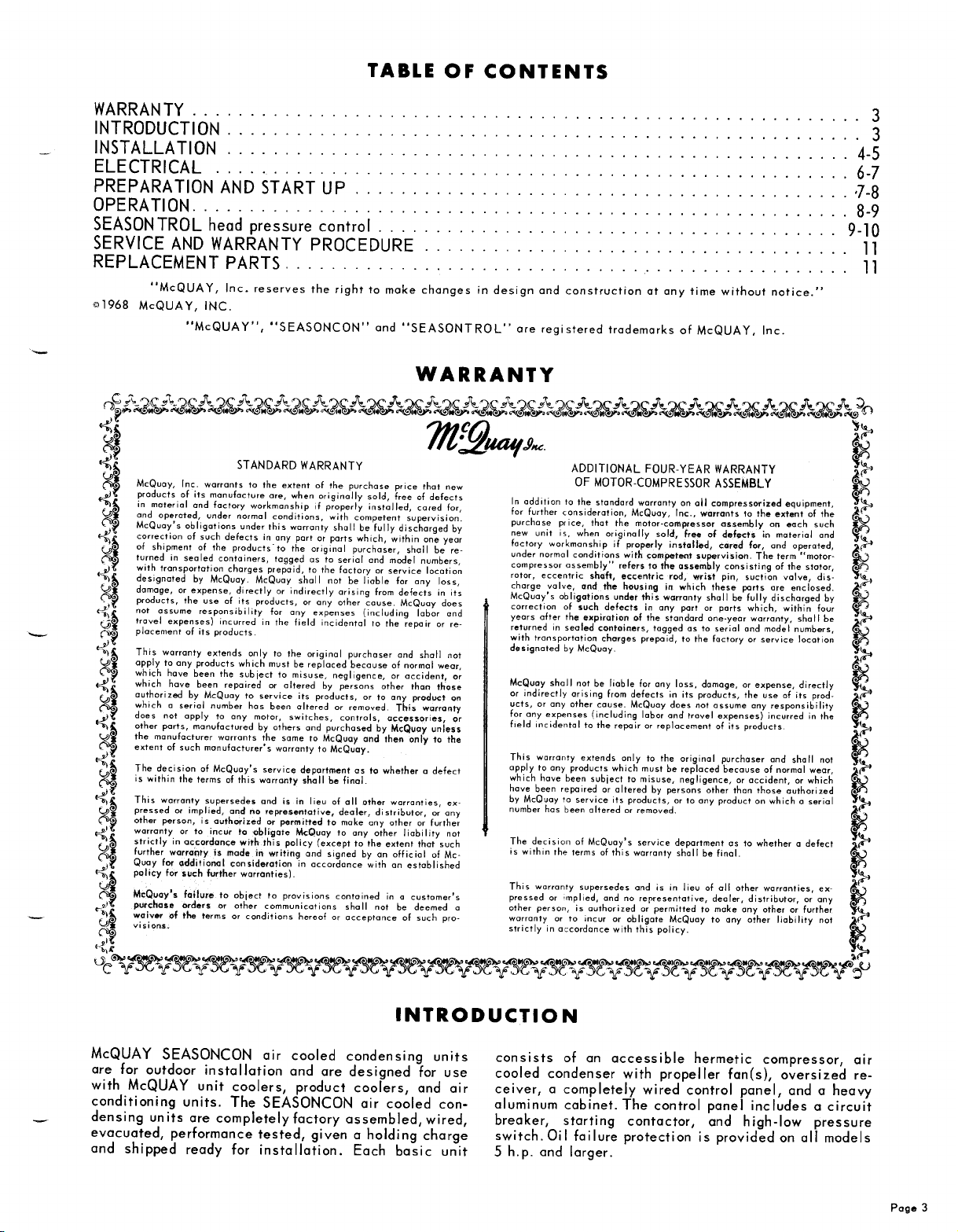
INSTALLATION
GENERAL - Commercial equipment of this type is intended for installation by qualified refrigeration mechanics. As a condition of the warranty, the check,
test, and startup procedure must be performed by such
personnel and properly reported on the form provided.
Failure to do so voids the warranty. Arrangement for
service should be made prior to installation,
not included in the warranty or the catalog price. See
warranty terms on Page 11.
INSPECTION
items should be carefully checked against the bill of
lading, to be sure all crates and cartons have been
received. All units should be carefully inspected for
damage when received. Visible or
should be reported immediately to the carrier, and a
claim filed for damage.
should be checked, to be sure it agrees with the power
supply available.
LOCATION
channels for rigging the unit. Be sure to use spreaders to avoid any possible damage to the unit cabinet.
The condensing unit should be located so that all
four sides of the unit have free area for air flow and
access room. Be sure to orient the unit so the air discharge is not
SEASONCON condensing units draw air in through
the coi I and discharge through the expanded metal
grille.
Mounting holes have been provided for securing the
unit. Vibration pads or isolators are recommended for
rooftop installation. The units must be mounted level.
-
When the equipment is received, all
concealed
The electrical nameplate
-
Holes have been provided in the unit
facing
the prevailing winds. All AHP
as it is
damage
SERVICEABILITY
doors are provided on either side of the unit for quick
access to the compressor, fan motor(s), unit piping
and control box. In addition, all other exterior unit
panels are removable, to provide complete access to
all areas.
REFRIGERANT PIPING
should be installed according to standard practice
and should follow latest
tions.
prevent wear and vibration. Suction and liquid line
sizing tables on Page 5 show recommended line sizing
for R-12 and R-502.
vent foreign material from entering the compressor. A
Schroeder tap on the filter inlet allows a check on
filter pressure drop.In addition, a liquid line
drier, moisture indicating sight glass, and solenoid
valve must be installed, by others, for safe operation.
SOLENOID VALVE MUST BE INSTALLED. AHP
SEASONCON air cooled condensing units are designed
to operate with a liquid pumpdown cycle.
necting refrigerant lines during the brazing operation,
to prevent oxidation of the piping interior. Soft soldered joints are not acceptable.
FILTER-DRIERS, LIQUID LINE SOLENOID VALVE,
All lines should be checked and secured, to
A suction line filter is provided as standard, to pre-
It is especially important to note that A LIQUID
It is urged that dry nitrogen be run through the con-
-
Large, easily removed access
-
The refrigerant piping
ASHRAE
Guide recommenda-
filter-
AND MOISTURE INDICATING SIGHT GLASSES - No
fi Iter-drier,
dicating sight glass is furnished with the condensing
unit; however, they must be installed in the liquid
line of every unit.
liquid line solenoid valve, or moisture in-
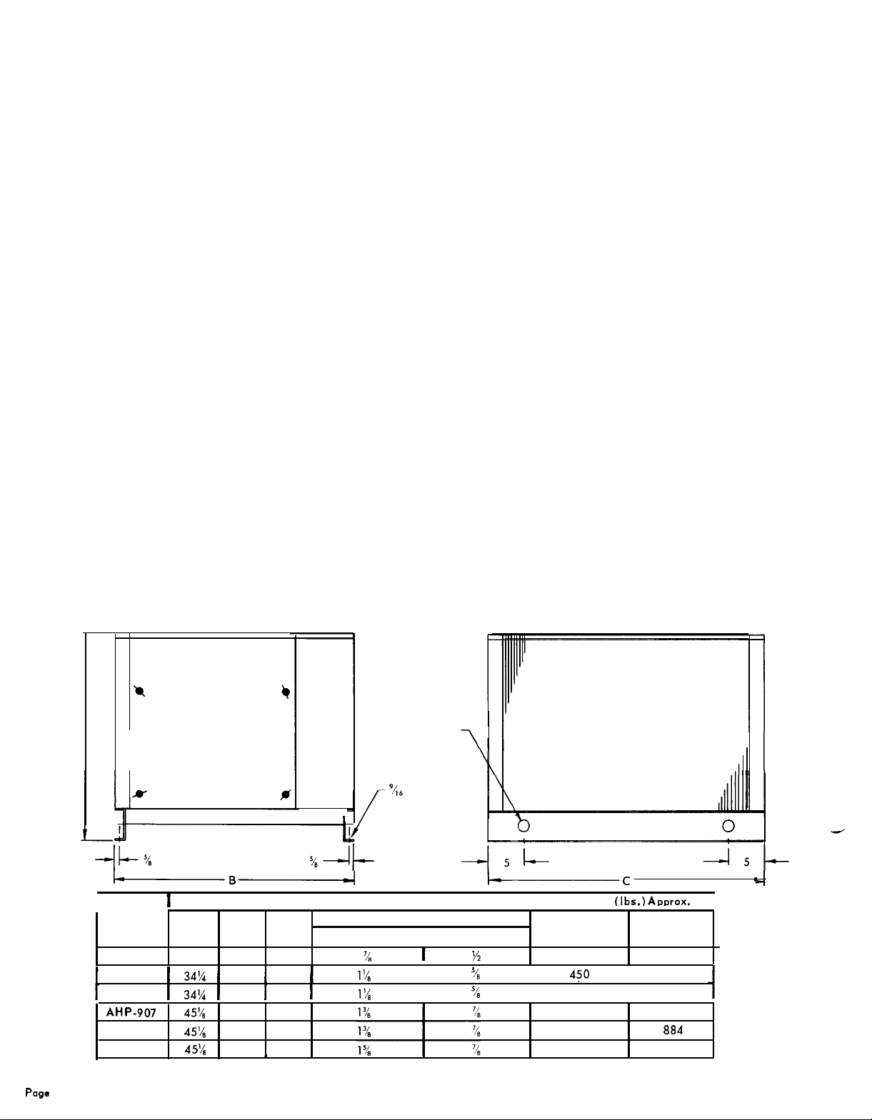
FIGURE 1
*
CONTROL AND
PIPING ACCESS
+
r
-B-
I I
MODEL
NUMBER
AHP-902
AHP-903
AHP-905
AHP-907
AH P-908
AHP-910
28%
1
34%
1
34%
45’4
45’4
45%
A
B C
32% 38
1 391
1
39
45
46% 63
46%, 63
DIMENSIONS (Inches)
SUCTION (ODM)
1
40
40
41
1
1
DIMENSION DIAGRAM
LIFTING
HOLES (4)
‘46
DIA. MTG.
HOLES (4)
CONNECTIONS
LIQUID (ODF)
‘/,
1’4
1%
I
I ‘4 I
‘/2
‘/8
I
iC
WEIGHTS
OPERATING
310
4$0
568
673
a33
940
(Ibs.) Ammx.
SHIPPING
350
494
I
612
720
884
991
I
Page
4
Page 5

Page 6

ELECTRICAL
CONTROL PANEL
The AHP SEASONCON air
cooled condensing unit control panel is fabricated of
heavy gauge steel for ruggedness and is located behind a unit access panel for safety and weather protection. Controls are reached easily by opening the
hinged control box door.
FIELD WIRING
Wiring of the systems should be
done in accordance with all applicable codes and
ordinances.
Main power leads must be connected to the condensing unit circuit breaker. Table 3 gives the recommended lead wire sizes for not more than three conductors
in a rocewoy.
Maximum supply voltage variation is
+
10% of the
nameplate value. Phase voltage unbalance must not
exceed 2%.
The condensing unit must be wired to operate on a
pumpdown cycle. Consequently, it is necessary to
install a liquid line solenoid valve in the system to
operote on signal from a room thermostot. In addition,
interlocking of the evaporator fan motor is essential
so the condensing unit wi II not run unless the evapo-
rator fan motor is running.
This can be accomplished
by wiring evaporator fan motor relay auxiliary con-
TABLE 3
ELECTRICAL DATA
tacts in series with the compressor contactor holding
coi I. A typical AHP condensing unit schematic wiring
diagram is shown in Diagram 1.
CIRCUIT BREAKER
The circuit breaker for the
compressor and condenser fan motor is located in the
control box. Some electrical
codes
also require a
fused disconnect switch (furnished by others) in the
unit supply circuit, located within easy reach or within sight of the unit.
CRANKCASE HEATERS
-
The compressors are
equipped with crankcase heaters installed under the
crankcase to retard refrigerant from migrating to the
crankcase and condensing in the oil.
When a system is started up initially in cold weather, the power to the heaters should be turned on for
at least 8 hours before the compressor is started, to
minimize liquid slugging. When shutting down the
system for on extended period, care should be taken
that ower to the heater is left on. This may be
camp rshed
P.
by opening the unit circuit breaker since
ac-
the heater is connected to the line side of the circuit
breaker.
907A-H1208-240/60/3
907A.M
._.
907A-L
908A.L
910A-H
910A-L
NOTES:
1
20%240/60/3
--
208.240/60/3
208.240/60/3
208-240/60/3
208.240/60/3
(A)
Allowable Voltage Tolerances
Nomeplote
(B) Wire sizing
See Notional Electric Code.
(C) Recommended power lead wires
ing to the National Electric Code. Voltage drop has not been included; therefore, it is recommended that leads be as
short as possible. For applications above
208-240:
amps
equal 125% of the FLA for the largest motor plus 100% of the FLA for
1
27.0 135.0 4.0
1Rl
7
1
_ ..-
14S.O
._._
31.2 145.0 10.0 43
1
(24.i.O
31.2 145.0
46.4
46.4 215.0
Min. 187V; Max. 264V.
215.0
(2) 4.0
(2) 4.0
based
on not more than 3 conductors in a rocewoy at 86F ambient air. Wire accord-
86F,
consult N.E.C.
4.0
.._
1
10.0 38
1
10.0
(2) 10.0
(2) 10.0
(2) 10.0
I
43
47
66
66
RECOMMENDED POWER
LEAD WIRE SIZE
8
I
6
I
6
6 6
4
4 4
all
other motors in the unit.
8
8
8
4
-
Page 6
Page 7

DIAGRAM 1
Hl
TYPICAL SCHEMATIC WIRING DIAGRAM
CBl
COMPRESSOR
y-1
COMPONENT LEGEND
Hl
-CRANKCASE HEATER
CBl
-CIRCUIT BREAKER
Ml - CONTACTOR
-
FAN MOTOR
:: -
CAPACITOR
OPl -OIL
PC1 - PRESSURE SWITCH
FAILURE SWITCH
PC1
PREPARATION AND START UP
EVACUATING AND CHARGING
unit as shipped from the factory has been checked
under normal operating conditions and given a holding
charge of the refrigerant indicated on the unit serial
plate.
Care should be taken to prevent dirt and moisture
from entering the system during installation. To this
end, always cap or seal open refrigerant lines,use
clean, dry tubing or pipe, and use good refrigeration
practices.
To assure a dry, clean system, a triple evacuation
procedure should follow the system leak check. Break
the initial and second vacuum with dry refrigerant and
then evacuate to at least 500 microns before charging
the system. Table 4 on Page 8 shows the condensing
unit charge required for various minimum design ambient temperatures. This table shows the condensing
unit charge only. The liquid and suction line charge
and the evaporator charge must be added to determine
the total charge.
LOW PRESSURE CONTROL SETTING
-
The
condensing
-
Because the
CONDENSER
FAN MOTOR
system is designed to operate with a pumpdown cycle,
the operation of the compressor is dependent on the
low pressure switch. It is important, therefore, that
the low pressure switch be set properly for the lowest
ambient in which the condensing unit is to be operated.
Table 5 on Page 8 shows the correct cut-in settings
for various ambient temperatures. The cut-out setting
should be set low enough to avoid short cycling. Compressor operation should be observed to be sure the
settings are correct for the particular applications.
OIL CHARGE
erant charge required in an air cooled condensing unit
system, it is usually necessary to put additional oil
into the system. The oi I level should be watched care-
fully upon initial startup and for some time thereafter.
At the present time, Suniso #3G oil is the only oil
approved by
The oil level should be maintained at a level about
midpoint of the glass bullseye on the compressor body
during operation.
-
Because of the rather large refrig-
Copeland
for use in these compressors,
Page 7
Page 8

Page 9

START UP AFTER EXTENDED SHUTDOWN
A. Inspect all eqwipment.
B. Check face of condenser coil for paper or other
obstruction that might be lodged on the surface.
C. Open the suction and discharge service valves.
D. Turn on the electrical power to the system.
E. Open the liquid line shut-off valve or valves.
-
SEASONTROL head pressure control
F. Start the evaporator fan motors.
G. Check crankcase heater & crankcase warmth.
H. Start the unit by closing the circuit breaker.
ten for unusual sounds indicating liquid slugging.
I. After the unit has run for several minutes, check
the oil level in the crankcase, and observe flow
through the refrigerant sight glass for sufficient
refrigerant charge.
Lis-
SEASONTROL head pressure control is a factory in-
stalled system based on liquid refrigerant flooding
back into the condenser coil, thereby reducing the
effective condenser surface available for condensing.
The SEASONTROL head pressure control system is
an improved method of head pressure control incorporating two modulating valves.
The main, or liquid line, valve 239 series is normally closed, and opens on pressure rise in the condenser. This valve is located in the liquid line between the condenser and receiver. The gas, or bypass,
valve (237 series) is normally
pressure rise in the receiver. This valve is located
between the compressor discharge line and the receiver. See Figure 2.
The head pressure control system operates as fol-
lows: On system startup, the bypass valve is normally
open and the main or liquid line is closed. Hot gas
moves from the compressor, with part going into the
condenser, and part going through the bypass circuit
FIGURE 2
open and
closes on
SEASONTROL III head pressure control
SYSTEM PIPING DIAGRAM
through the open valve and into the receiver. The by-
pass gas goes directly into the receiver to maintain
or build up pressure in the receiver. As the compressor continues to run, hot gas condenses in the con-
denser and raises the liquid level since the liquid
valve on the leaving side of the condenser is still
closed. As the liquid level in the condenser rises, the
condensing capacity of the condenser decreases and,
as a result, the head pressure rises. As the pressure
in the condenser rises to the control point of the
valve, the liquid valve starts modulating towards the
open position, permitting liquid to leave the condenser and flow into the receiver. At the same time, the
bypass valve starts modulating towards the closed
position, limiting the hot gas flow into the receiver.
The modulation of the two valves maintains the proper
liquid level in the condenser, to maintain proper head
pressure.
liquid from the condenser to near saturation tempera-
ture.
The bypass gas also warms up the cold
COMPRESSOR
DISCHARGE
TYPE 237
HOT GAS VALVE
CHECK VALVE-
I
r.
I
/
RECEIVER
,Y
TYPE 239
LIQUID VALVE
/
L
;
TO SUBCOOLER
LIQUID SHUTOFF
LIQUID TOEXPANSIONVALVE
Page 9
Page 10

VALVE CHECKING AND SETTING
TROL head pressure control valves are factory set
and checked to maintain a minimum head pressure
equivalent to 95 F condensing for R-12 ond 85 F
condensing for R-502. The valves have a nominal 15
PSIG
modulating range between fully open and fully
closed positions. Factory settings ore 110
R-12 valves and 175
Referring to Figure 3, it is to be noted that on pressure increase on the system,
compress the bellows and the valve stroke will be up
or toward the adjustment end of the valve. This applies to both the liquid and gas valves. The valve
travel is nominal 1/10" for all models.
As indicated in the diagrams, the adjustment of the
nut in a clockwise direction will increase the modu-
lating pressure point. A wide bladed screwdriver or
similar instrument inserted into the nut slot moy be
used for making the adiustment.
The modulating pressure point and range may be
checked as follows:
A. Make up a “depth gouge” for inserting through
the adjusting nut opening and long enough to hit
the bottom of the bellows section, as indicated in
Figure 3. A piece of insuloted wire, 8 to 12 gouge,
PSIG
for R-502 valves. the top of the valve.
the
-
The
SEASON-
PSIG
for
pressure wi II tend to
is a simple and convenient material from which to
make a gauge.
valve,
OS shown in the diagram. Trim off the
lotion, for about one inch off the end to be inserted, and at a point just above the top of the valve
at the other end. When in use, hold the gauge
down lightly against the bellows and sight olong
B.
A high side gauge should be connected to a line
so it can be brought to the valve area, unless a
second person is available to call out head pres-
sure readings while valve observations ore made.
Start up the unit and note pressures at which the
C.
valve bellows rise. We assume that the pressure
was low enough at startup so that the bellows is
in the down position. The test may also be done
in reverse by running the system up to o high
ressure,
head p
servations at what pressure the valve changes
position.
The valves should be set so that the movement of
D.
both
valves
Be sure system hos sufficient refrigeront before
E.
making any change in valve adiustment.
FIGURE 3 SEASONTROL head pressure control
TYPE 239 LIQUID VALVE
8A. SECTIONAL VIEW
Insert a piece of the wire into the
insu-
stopping the unit, and making ob-
is through the some pressure range.
8B.
CONTROL SETTING
COVER
ADJUSTING NUT
CONTROL SPRING
VALVE SEAT
r l/10”
TRAVEL
FEELER GAUGE INSERTE
Page 10
LIQUID
OUTLET
Page 11

SERVICE AND WARRANTY PROCEDURE
MOTOR-COMPRESSOR
poration has stocking
stock of replacement motor-compressors and service
parts to serve refrigeration contractors and servicemen
as required.
When a motor-compressor fails in warranty, the in-
operative motor-compressor can be taken to any author-
ized
Copeland
exchange, or an advance replacement can be obtained.
Credit is issued on the returned motor-compressor
upon receipt and factory inspection of the inoperative
motor-eompressor. In this transaction, be certain that
the motor-compressor is received from the field that
tests satisfactory, a service charge plus a transportation charge will be charged against its original credit
value.
On all out-of-warranty motor-compressor failures,
Copeland
and/or replacement as described above. The credit
issued on the returned motor-compressor will be deter-
mined by the repair charge established far that partic-
ular unit.
Wholesaler for an
offers the same field facilities for service
-
Copeland
wholesalers
Refrigeration Cor-
who maintain a
over-the-counter
IN-WARRANTY RETURN MATERIAL PROCEDURE
(Other Than Compressors) Material may not be re-
turned except by permission of authorized factory
service personnel of McQUAY, Inc. at Minneapolis,
Minnesota. A “Return Goods” tag will be sent to be
included with the returned material. Enter the information as called for on the tag, in order to expedite
handling at our factories and prompt issuance of
credits.
The return of the part does not constitute an order
for replacement. Therefore, a purchase order must be
entered through your nearest McQUAY representative
or directly with McQUAY, Inc. at Minneapolis, Minne-
sota. The order should include part name, part number,
model number and serial number of the unit involved.
Following our personal inspection of the returned
part, and if it is determined that the failure is due to
faulty material or workmanship, and is in warranty,
credit will be issued on customer’s purchase order.
All parts shall be returned to the pre-designated
McQUAY factory, transportation charges prepaid.
REPLACEMENT PARTS
Replacement service parts can be ordered through your unit involved. Replacement parts for the motornearest
QUAY, Inc. at Minneapolis, Minnesota. Always pro-
vide complete description of service part, part number
(if known), plus complete serial and model number of
McQuay
representative or directly with Mc- compressor assembly can be procured direct from your
nearest franchised
Wholesaler.
Copeland
Refrigeration Corporation
-
Page 11
 Loading...