

Page 1
Installation and Maintenance Manual
IM 967-1
Group: Controls
Part Number: IM 967-1
Date: March 2012
Supercedes: IM 967
MicroTech® III Chiller Unit Controller
BACnet® Communication Module (MS/TP)
Pathfinder™ Chiller, Model AWS
Air-Cooled Scroll Compressor Chiller, Model AGZ-D
Use this manual to physically install the BACnet MS/TP Communication Module into the MicroTech III chiller
unit controller and connect the chiller unit controller to your network. Use the appropriate Engineering Data
(ED), known as the Protocol Information document, to integrate the unit into your network. The Protocol
Information document contains addressing details, BACnet® protocol information, and a list of the data points
available to the network. See the Reference Documents section of this manual for Protocol Information
document numbers. MicroTech III control integration literature is available from your local Daikin McQuay
sales representative and www.daikinmcquay.com.
© 2012 McQuay International
NOTICE
Page 2

Contents
Figures................................................................................................................................................... 2
Revision History.................................................................................................................................... 3
Reference Documents ........................................................................................................................... 3
Limited Warranty.................................................................................................................................. 3
General Information.............................................................................................................. 4
Hazard Identification Messages ............................................................................................................ 4
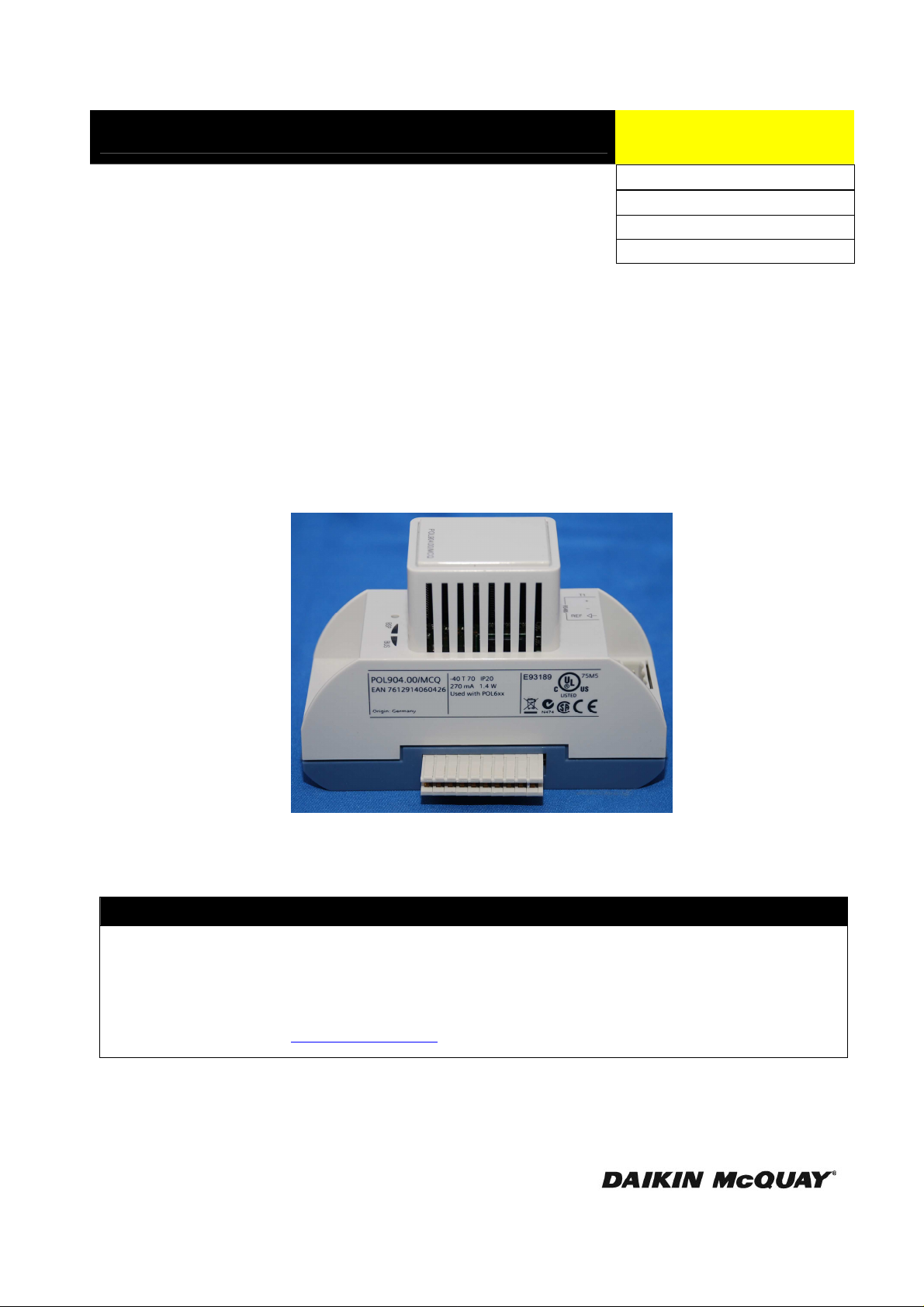
Description............................................................................................................................................ 5
Application............................................................................................................................................ 5
Component Data.................................................................................................................................... 5
Light Emitting Diodes (LEDs).......................................................................................................... 6
BACnet Network Connector............................................................................................................. 7
Board-To-Board Connector .............................................................................................................. 7
Installation .............................................................................................................................9
Contents of the BACnet Communication Module Kit........................................................................... 9
Installing a new BACnet Communication Module................................................................................ 9
To install a BACnet Communication Module................................................................................... 9
Replacing an Existing BACnet Communication Module.................................................................... 10
To Replace a BACnet Communication Module.............................................................................. 10
Integration............................................................................................................................11
Configuring the BACnet Communication Module.............................................................................. 11
BACnet MS/TP Configuration using the Keypad/Display.............................................................. 11
Changing the BACnet MS/TP Data Transmission Rate.................................................................. 12
Service Information.............................................................................................................15
Test Procedures................................................................................................................................... 15
Parts List ............................................................................................................................................. 15
Installation Kit................................................................................................................................. 15
Figures
Figure 1. BACnet MS/TP Communication Module Attached to MicroTech III Chiller Unit Controller5
Figure 2. BACnet MS/TP Communication Module Components......................................................... 6
Figure 3. BACnet MS/TP Communication Module and Knockout ...................................................... 7
Figure 4. Diagram of Board-to-Board Connector ................................................................................. 8
Figure 5. BACnet MSTP Communication Module with Board-to-Board Connector Inserted.............. 8
Figure 6. MicroTech III Chiller Unit Controller Password Menu and Main Features ........................ 12
Figure 7. MicroTech III Chiller Unit Controller MSTP Setup Menu – Change Baud Rate................ 13
Figure 8. MicroTech III Chiller Unit Controller MSTP Setup Menu – Apply Change....................... 13
2 IM 967-1
Page 3

Revision History
IM 967 October 2009 Initial release
IM 967-1 October 2010 Updated OMM 998 to OM 1051. Added AGD Model.
IM 967-1 March 2012 Updated with Daikin McQuay logo and associated references
Reference Documents
Number Company Title Source
ANSI/ASHRAE 1352004
IM 1002 (50Hz )
IM 997 (60Hz)
OM 1051
ED 15120 McQuay International MicroTech III Chiller Unit Controller Protocol
OMM 1087 McQuay International Air-cooled Scroll Chiller, Model AGZ Operation Manual www.daikinmcquay.com
American Society of
Heating, Refrigerating and
Air-Conditioning Engineers
McQuay International
McQuay International
BACnet® A Data Communication Protocol for Building
Automation and Control Networks
Pathfinder™ Air Cooled Chiller Installation Manual www.daikinmcquay.com
Pathfinder Air Cooled Chiller Operation Manual
Information, BACnet and LONW
ORKS
Networks
www.ashrae.org
www.daikinmcquay.com
www.daikinmcquay.com
Limited Warranty
Consult your local Daikin McQuay Representative for warranty details. Refer to Form 933-43285Y.
To find your local Daikin McQuay Representative, go to www.daikinmcquay.com.
Notice
Copyright © 2012 McQuay International, Minneapolis MN. All rights reserved throughout the world.
McQuay reserves the right to change any information contained herein without prior notice. The user is
responsible for determining whether this software is appropriate for his or her application.
® ™ The following are tradenames or registered trademarks of their respective companies: BACnet
from the American Society of Heating, Refrigerating and Air-Conditioning Engineers, Inc.; Windows
from Microsoft Corporation; D-Net, Pathfinder, Daikin McQuay and MicroTech III from McQuay
International.
IM 967-1 3
Page 4

General Information
This manual contains the information you need to install the BACnet® Communication Module on a
MicroTech III Chiller Unit Controller, incorporate it into the BACnet network, and maintain it.
Hazard Identification Messages
Dangers indicate a hazardous situation that will result in death or serious injury if not
avoided.
Warnings indicate potentially hazardous situations, which can result in property damage,
severe personal injury, or death if not avoided.
Cautions indicate potentially hazardous situations, which can result in personal injury or
equipment damage if not avoided.
DANGER
!
WARNING
!
CAUTION
!
WARNING
!
Electric shock hazard. Can cause personal injury or equipment damage.
This equipment must be properly grounded. Connections and service to the MicroTech III
Chiller Unit Controller must be performed only by personnel knowledgeable in the
operation of the equipment being controlled.
CAUTION
!
Static sensitive components. Can cause equipment damage.
Discharge any static electrical charge by touching the bare metal inside the control panel
before performing any service work. Never unplug cables, circuit board terminal blocks, or
power plugs while power is applied to the panel.
NOTICE
This equipment generates, uses and can radiate radio frequency energy and, if not
installed and used in accordance with this instruction manual, may cause interference to
radio communications. It has been tested and found to comply with the limits for a Class
A digital device, pursuant to part 15 of the FCC rules. These limits are designed to
provide reasonable protection against harmful interference when the equipment is
operated in a commercial environment. Operation of this equipment in a residential area
is likely to cause harmful interference in which case the user will be required to correct the
interference at his or her own expense. Daikin McQuay disclaims any liability
resulting from any interference or for the correction thereof.
4 IM 967-1
Page 5
Description
Application
The MicroTech III® BACnet Communication Module incorporates a MicroTech III Chiller Unit
Controller into a BACnet local area network (LAN). It supports the BACnet MS/TP (EIA 485) data
link layer (physical layer.)
The BACnet Communication Module is a printed circuit board with a plastic enclosure that connects
to the left side of the D-Net™ Module as shown in Figure 1 or directly to the MicroTech III Chiller
Unit Controller. The BACnet Communication Module provides access to the MicroTech III Chiller
Unit Controller variables and parameters via BACnet.
Note: The D-Net module is an optional feature that provides remote monitoring and diagnostic
capability for certain models of Daikin McQuay chillers. Please refer to supporting
literature, available on www.daikinmcquay.com, for additional details about D-Net.
The BACnet Communication Module connects the MicroTech III Chiller Unit Controller to a
building automation system (BAS) on a BACnet local area network. It is the interface for the
exchange of BACnet objects between the network and the unit controller. Refer to the MicroTech III
Chiller Operation Manual, available on www.daikinmcquay.com, for keypad details.
Component Data
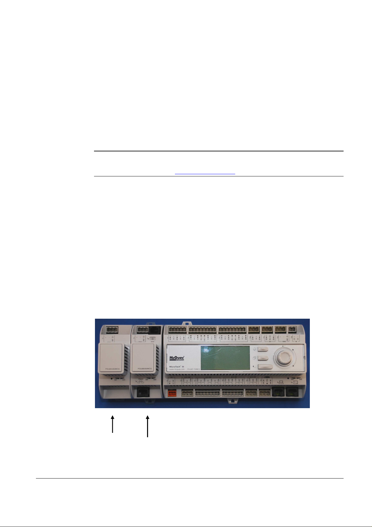
Figure 1 shows the BACnet Communication Module, located on the far left-hand side of the image
below. It is connected to the D-Net Module, which is mounted directly to the unit controller. Figure
2 shows the important features of the BACnet Communication Module.
Figure 1. BACnet MS/TP Communication Module Attached to MicroTech III Chiller Unit
Controller
BACnet MS/TP
Communication
Module
IM 967-1 5
D-Net Module attached to unit
controller
Page 6

Figure 2 shows the location of the major components of the BACnet MS/TP Communication Module.
Figure 2. BACnet MS/TP Communication Module Components
Network Connector
+ - Ref
BUS LED
BSP LED
Light Emitting Diodes (LEDs)
The BACnet Communication Module has a BSP LED and a BUS LED to indicate communication
activity and status of the BACnet Communication Module. These indicators are visible when the
communication module is connected to the MicroTech III Chiller Unit Controller and the unit is
powered on (see Figure 2).
BSP LED
The BSP LED indicates the communication state between the BACnet Communication Module and
the MicroTech III Chiller Unit Controller. The table below describes the status of the BSP LED.
BSP LED Color Meaning
Flashing between Red & Green Board Support Package (BSP) upgrade in progress
Green Communication is established with the unit controller
Communication is established between the communication
module and the unit controller.
Yellow The communication module is capable of communicating to
the unit controller. However, communication is not
established.
Red flashing with 2Hz Red flashing with 2Hz = Software error.1
Red Hardware error. 1
1
In the event that this should occur, cycle power to the unit controller to attempt to clear the problem. Contact
the Controls Customer Support Group at 866-462-7829 for additional assistance if necessary.
6 IM 967-1
Page 7

connector
BUS LEDs
The BUS LED indicates the communication status between the BACnet Communication Module and
the BACnet MS/TP network. The table below describes the status of the BUS LED.
BUS LED Color Meaning
Green The unit controller is capable of communicating to the network.
Red The unit controller is not capable of communicating to the network.
Orange / Yellow Communication module is initializing.
BACnet Network Connector
An RS485 connector connects the BACnet Communication Module to the MS/TP Network and has
three pins: + , -, and ref (see Figure 2).
Board-To-Board Connector
The board-to-board connector connects the MicroTech III Chiller Unit Controller to the BACnet
Communication Module (see Figures 3, 4 and 5).
Figure 3. BACnet MS/TP Communication Module and Knockout
Knockout
permanently
Board-to-board
removed
Slot in module must line
up with baffle in boardto-board connector
IM 967-1 7
Page 8

Figure 4. Diagram of Board-to-Board Connector
Figure 5. BACnet MSTP Communication Module with Board-to-Board Connector Inserted
8 IM 967-1
Page 9

!
Installation
The following section describes how to field install a new BACnet Communication Module or replace
an existing BACnet Communication Module on the MicroTech III Chiller Unit Controller so that it
can be incorporated into the BACnet network.
CAUTION
Electrostatic discharge hazard. Can cause equipment damage.
This equipment contains sensitive electronic components that may be damaged by
electrostatic discharge from your hands. Before you handle a communications module, you
need to touch a grounded object, such as the metal enclosure, in order to discharge the
electrostatic potential in your body.
Contents of the BACnet Communication Module Kit
The following is the list of items included in the field-installed kit:
• The BACnet Communication Module
• Board-to-board connector
• Network connector (attached to module)
• Installation Manual (IM 967)
Installing a new BACnet Communication Module
Follow these steps to install a BACnet Communication Module on the unit controller. The BACnet
Communication Module can be connected directly to the unit controller itself or to an existing
module, if one is attached.
To install a BACnet Communication Module
WARNING
!
Electric shock hazard. Can cause personal injury or equipment damage.
This equipment must be properly grounded. Only personnel knowledgeable in the operation of the
equipment being controlled must perform connections and service to the MicroTech III Chiller Unit
Controller.
1. Set the Unit On/Off Switch to “Off” from inside the control panel of the unit. This must be done
prior to installing a new communication module. Refer to Figure 3, IM 1122 (Pathfinder chiller)
or OMM 1087 (AGZ-D chiller), available on www.daikinmcquay.com.
2. Remove power from the unit controller.
3. Remove the knockout on the far left end of the unit controller itself (or additional module, if
present). See Figure 3.
Note: To prevent damage to the unit controller, insert a small screwdriver or other tool to the tab on
the bottom of the unit controller and pull the screwdriver away from the controller.
IM 967-1 9
Page 10

4. Remove the knockout on the right side of the BACnet Communication Module.
5. Insert the board-to-board connector into the BACnet Communication Module (see Figures 3 and
4). Note that it only fits one way and that the baffles must line up with corresponding slots in
BACnet Communication Module and the unit controller (see Figures 4 and 5).
6. Insert the other end of the board-to-board connector to the far-left side of the unit controller or
other device (i.e. module), if attached (see Figure 1).
7. Connect the BACnet Communication Module to the network by inserting a network cable into the
communication module’s network connector (see Figure 2).
8. Power up the unit controller.
9. The unit controller automatically resets itself approximately 30 seconds after it is powered up.
This reset is necessary so that the BACnet Communication Module is synchronized with the unit
controller.
Note: There is a limit of three devices that can be attached to the left side of the unit controller.
Replacing an Existing BACnet Communication Module
Follow these steps to remove an existing BACnet Communication Module from unit controller and
replace it with a new BACnet Communication Module.
To Replace a BACnet Communication Module
WARNING
!
Electric shock hazard. Can cause personal injury or equipment damage.
This equipment must be properly grounded. Only personnel knowledgeable in the operation of the
equipment being controlled must perform connections and service to the MicroTech III Chiller Unit
Controller.
1. Set the Unit On/Off Switch to “Off” from inside the control panel of the unit. This must be done
prior to replacing a communication module. Refer to Figure 3, IM 1122 (Pathfinder chiller) or
OMM 1087 (AGZ-D chiller), available on www.daikinmcquay.com.
2. Remove power from the unit controller.
3. Locate the BACnet Communication Module to the left of the unit controller (see Figure 1).
4. Pull the network cable connector from the BACnet Communication Module.
5. Grasp the BACnet Communication Module and carefully pull it from the unit controller (or from
an adjacent module, if it is attached to one.)
6. Install the new BACnet Communication Module (see steps 2-5 from previous section).
7. Insert the network cable connector into the BACnet Communication Module (see Figure 2 for
location of network connector).
8. Power up the unit controller.
10. The unit controller automatically resets itself approximately 30 seconds after it is powered up.
This reset is necessary so that the BACnet Communication Module is synchronized with the unit
controller.
10 IM 967-1
Page 11

Integration
Once the BACnet Communication Module has been properly installed on the MicroTech III Chiller
Unit Controller, it is then necessary to configure the unit controller for integration into a Building
Automation System (BAS) via the BACnet MS/TP network. The configuration process is described
in the following section.
Configuring the BACnet Communication Module
The BACnet Communication Module is configured using the keypad/display on unit controller.
Table 1 describes all of the available BACnet MS/TP network parameters used to establish
communication between the unit controller and the BAS. The items shown in boldface are required
for minimum network configuration. Table 1 also defines the factory defaults (as indicated by the
Initial Value/Note column) for each network parameter.
See your system integrator for additional information regarding proper BACnet MS/TP addressing.
Refer to the MicroTech III Chiller Unit Controller Operation Manual for additional information on
using keypad/display to set unit parameters and factory defaults for unit setpoints. Refer to Protocol
Document ED 15120, available on www.daikinmcquay.com, for descriptions of the available BACnet
objects.
BACnet MS/TP Configuration using the Keypad/Display
1. If you have not already entered a password, select Enter Password from the Main Menu screen
(i.e. turn the circular knob on the unit controller until the cursor is in the proper location) and
press Enter (i.e. press down on the knob). See Figure 6.
a. If you are not at the Main Menu and need to enter a password, press the Back button from
any other menu screen until you reach the Main Menu and follow step 1. See Figure 6 for the
location of the Back button.
b. If you have already entered a password, skip to step 3. See Figure 6 if you are not certain
whether or not a password has been entered.
2. Enter Password: 5321 and then press Enter.
3. Scroll down to View/Set Unit (i.e. turn the knob clockwise) and press Enter.
4. Scroll down to BACnet MSTP Setup and press Enter.
Note: The BACnet MSTP Setup menu only appears if a BACnet Communication Module
installed correctly (see Installation section of this document for details.) If the BACnet
Communication Module is installed correctly and this menu still does not appear, cycle
power to the unit controller and repeat the procedure above.
5. Scroll down to MSTP Address (MAC Address) and press Enter. Change this parameter to the
value specified by the network administrator. Press Enter again to confirm selection.
Note: The BACnet MS/TP Media Access Control (MAC) address is a one-octet address that must
be set during the BACnet Communication Module configuration. The MAC address must
be unique to the MS/TP network and have a valid range of 0-127.
6. Change additional parameters as required for your network (see Table 1).
7. Set Apply Changes to Yes. This will save the changes and cycle power to unit controller.
IM 967-1 11
Page 12

8. Navigate back to the BACnet MSTP Setup menu (see steps 1-4) to verify the settings of all
parameters. This procedure may take a minute while the BACnet Communication Module
powers up.
Figure 6. MicroTech III Chiller Unit Controller Password Menu and Main Features
Back button Circular knob (press
down to Enter value)
Changing the BACnet MS/TP Data Transmission Rate
The BACnet Communication Module is set with a factory default baud rate of 38400 bps. Additional
baud rate options (in bps) include: 9600, 19200, 38400, and 76800. The following section describes
how to change the BACnet MS/TP data transmission rate via the keypad display.
WARNING
!
Electric shock hazard. Can cause personal injury or equipment damage.
This equipment has exposed electrical connections inside BACnet Communication Module.
Only personnel that are knowledgeable in the operation of this equipment must perform
connections and service to the BACnet Communication Module.
1. If you have not already entered a password, select Enter Password from the Main Menu screen
(i.e. turn the circular knob on the unit controller until the cursor is in the proper location) and
press Enter (i.e. press down on the knob). See Figure 6.
a. If you are not at the Main Menu and need to enter a password, press the Back button from
any other menu screen until you reach the Main Menu and follow step 1. See Figure 6 for the
location of the Back button.
b. If you have already entered a password, skip to step 3. See Figure 6 if you are not certain
whether or not a password has been entered.
2. Enter Password: 5321 and then press Enter.
3. Scroll down to View/Set Unit (i.e. turn the knob clockwise) and press Enter.
4. Scroll down to BACnet MSTP Setup and press Enter.
5. Change the Baud Rate by scrolling to Baud Rate and press Enter to selected desired baud rate
(see Figure 7 to view a baud rate that has been changed to 76800 bps).
6. Scroll to ApplyMSTPChgs and set to Yes. This will save the changes and cycle power to the
unit controller (see Figure 8).
12 IM 967-1
Page 13

Figure 7. MicroTech III Chiller Unit Controller MSTP Setup Menu – Change Baud Rate
Figure 8. MicroTech III Chiller Unit Controller MSTP Setup Menu – Apply Change
IM 967-1 13
Page 14

acter Device Object Name.
No/Selecting Yes enables an internal resistor.
Table 1. BACnet MS/TP Network Configuration Parameters
Parameter Value (Range)/Definition Initial Value/Note
Apply Changes1
No-Yes/Setting this to yes will cycle
No
power to the controller to allow the
network setup changes to take place.
Name Up to a 17-char
Change this value as needed to match
installation parameters.
POL904_FF2BEE/This name must be unique
throughout the entire BACnet network. The
last 6 characters of the default are the last 6
digits of the MAC Address, which is printed on
a label located on the left end of the module.
Dev Instance
MSTP Address1
Baud Rate1
0-4194302/Device Instance of the BACnet
Communication Module.
0-127/ This is the MS/TP address of the
BACnet Communication Module.
9600-19200-38400-76800/ Data transfer
368136/This must be unique throughout the
entire BACnet network.
18/ Each device on the BACnet network must
have a unique MS/TP address.
38400
speed (bps).
Max Master
0-127/ This variable specifies the highest
127
possible address for master. Nodes and
shall be less than or equal to 127.
Max Info Frm 0-255/ This variable specifies the
10
maximum number of information frames
the BACnet Communication Module may
send before it must pass the token.
Unit Support Metric-English/Controls the type of units
English
that are passed through BACnet (English
or Metric).
Term Resistor1 No-Yes
Select No, if there is an external resistor or if
this unit is not the first or last unit on the
segment.
NC Dev 11 0-4194303/Alarm Recipient Device 1 0 (no device)/This is the device instance of the
BACnet workstation or device that will receive
the alarm notification. Use this in place of the
Recipient List in the Notification Class.
NC Dev21 0-4194303/Alarm Recipient Device 2 0 (no device)/This is the device instance of the
BACnet workstation or device that will receive
the alarm notification. Use this in place of the
Recipient List in the Notification Class.
BACnetBSP1 Basic Support Package Version 1.1.30s
1
Parameter only available via the keypad/display.
2
Items in boldface are required for minimum network configuration.
Note: If unit controller application software requires downloading in the field, the network
14 IM 967-1
configuration parameters revert to their default values. Please contact the Technical
Response Center at 877-349-7782 for assistance with upgrading unit controller application
software.
Page 15

Service Information
Test Procedures
If you can control the unit from its keypad, but you are not able to communicate with the unit via the
network, follows these steps:
• Check the network wiring
• Check the network parameters and verify that they are correct and that there are no duplicate devices
on the network
• Check communications
If the BACnet Communication Module still does not respond, contact the Controls Customer Support
Group at 866-462-7829.
Parts List
Installation Kit
Description Part Number
MicroTech III Chiller Communication Module, BACnet MS/TP kit
(kit includes communication module, board-to-board connector, and
Installation Manual)
350147414
IM 967-1 15
Page 16

This document contains the most current product information as of this printing. For the most current product
information, please go to www.daikinmcquay.com. All McQuay equipment is sold pursuant to Daikin McQuay
Standard Terms and Conditions of Sale and Limited Warranty.
 Loading...