

Page 1
Product Manual
Air-Cooled Scroll Compressor Chiller
AGZ 030AS - 065AS, Packaged Chiller
AGZ 030AM – 050AM, Chiller with Remote Evaporator
60 Hertz, R-22
PM AGZ-2
Group: Chiller
Effective: May 1999
Supersedes: PM AGZ-1
© 1997 McQuay International
Page 2
Table of Contents
Introduction...................................................................................................3
Features and Benefits....................................................................................3
Design Advantages........................................................................................4
Selection Procedure.....................................................................................10
Packaged Chiller, Model AS..................................................................................................................10
Remote Evaporator, Model AM ............................................................................................................12
Application Adjustment Factors..................................................................14
Performance Data........................................................................................17
Part Load Data.............................................................................................19
Sound Data..................................................................................................20
Pressure Drop Curves..................................................................................23
Electrical Data.............................................................................................24
Physical Data...............................................................................................30
AGZ-AS..................................................................................................................................................30
AGZ-AM.................................................................................................................................................32
Dimensional Data........................................................................................33
Application Data..........................................................................................36
Optional Features........................................................................................39
MicroTech...............................................................................................................................................40
Product Specification ..................................................................................41
NOTE: The Model AGZ 030AM through
AGZ 050AM chillers with remote
evaporators are not included in the ARI
Certification Program.
Our facility is ISO9002 Certified
"Illustrations cover the general appearance of McQuay International products at the time of publication and we
2 AGZ 030A through 065A Product Manual AGZ-2
"McQuay" is a registered trademark of McQuay International
reserve the right to make changes in design and construction at anytime without notice"
1997 McQuay International
Page 3
Introduction
Global
McQuay offers air-cooled chillers from 10 through 425 tons (35 – 1500 kW). This
manual covers two varieties of the scroll compressor, air-cooled Global Chiller Line:
AGZ 030AS through AGZ 065AS, Packaged Air-Cooled Chillers
AGZ 030AM through AGZ 050AM, Air-Cooled with Remote Evaporator.
Nomenclature
A G Z - XXX A S
Air-Cooled
Scroll Compressor
Model Size
AGZ AS Models ARI 550/590-98 Certified
Features and Benefits
Efficiency
Reliability
Application
S= Standard Cooling
M= Remote Evaporator
Design Vintage
• Cross-circuit compressor staging
• Copeland tandem scroll compressors
• Exceeds ASHRAE Std 90.1 for efficiency
• Rugged compressor design
• Factory installed operating and safety
controls
• Code and agency approval
Flexibility
Serviceability
Product Manual AGZ-2 AGZ 030A through 065A 3
• Complete factory assembly
• Sizes available in 5 ton increments
• All sizes available from stock
• SpeedTrol (optional)
• Small footprint
• Dual refrigerant circuits
• Easy servicing -- Electrical and refrigerant
components are readily accessible
• Two control options
Page 4

Design Advantages
The McQuay AGZ Air-Cooled Global Chiller is a product of the McQuay commitment to
offer quiet, reliable, energy efficient equipment. An approach incorporating high quality
compressors, state-of-the-art coil design, and innovative packaging.
Construction
Factory assembled and mounted on heavy-gauge painted phosphatized galvanized steel channel base.
This base distributes the unit weight for roof loading. Varied and convenient installation is possible by
virtue of the units small footprint.
Compressors
Copeland’s Compliant Scroll tandem compressors are used. These rugged hermetic compressors are
constructed with an integral cast iron frame, cast iron scrolls, three Teflon impregnated bearings, and
three oil filtration devices for each compressor.
Using Copeland's Compliant Scroll tandems provides four steps of modulation. One through four
compressors can run, depending on the load of the system, resulting in excellent part-load efficiency.
Each refrigerant circuit has two specially designed oil and gas equalization lines to control oil
migration.
The design also offers radial and axial compliance (no tip seals), a large internal volume for liquid
handling, a removable suction screen, and a rotary dirt trap and oil screen. In addition, the compressor
is self-compensating for wear, handles liquid and debris, and inherently yields the highest efficiency for
its class.
A fail-safe compressor by design-includes a solid state motor protection module, 4 individual motorwinding sensors, a patented internal discharge temperature probe, and a patented shutdown feature that
prevents reverse rotation. An internal discharge check valve helps prevent shutdown noise and comes
standard with high and low pressure taps with Schrader valves, a sight glass, an oil level adjustment
valve, and an off cycle crankcase heater.
Units are available in 60 Hertz electrical voltage configurations from 208 to 575 volt operating at
3500 RPM.
Condenser Coils
Condenser coils have internally enhanced seamless copper tubes arranged in a staggered row pattern.
The coils are mechanically expanded into McQuay lanced and rippled aluminum fins with full fin
collars. An integral subcooler circuit provides subcooling to effectively eliminate the possibility of
liquid flashing. The external condenser coils are fitted with a protective wire mesh guard.
Condenser Fans and Motors
Multiple direct drive dynamically balanced propeller fans operate in formed venturi openings at low tip
speeds for maximum efficiency and minimum noise and vibration. A heavy-gauge vinyl-coated fan
guard protects each fan.
Each condenser fan motor is heavy-duty, 3-phase with permanently lubricated ball bearings and
inherent overload protection. SpeedTrol option includes a single-phase motor with fan speed control
on the lead fan for each circuit. Totally enclosed fan motors are available as an option on all sizes.
4 AGZ 030A through 065A Product Manual AGZ-2
Page 5
Evaporator
The evaporator is direct expansion, shell-and-tube type with water flowing in the baffled shell side and
refrigerant flowing through the tubes. Two independent refrigerant circuits within the evaporator
serve the units dual refrigerant circuits.
The evaporator has a carbon steel shell and seamless high efficiency copper tubes roller expanded into
a carbon steel tube sheet. Water baffles are polypropylene to resist corrosion.
Refrigerant heads are carbon steel with multi-pass baffles to ensure oil return and are removable to
permit access to the tubes from either end. For water removal, 3/8" (10mm) vent and drain plugs are
provided on the top and bottom of the shell.
The evaporator is wrapped with an electric resistance heater cable and insulated with 3/4" (19mm)
thick vinyl nitrate polymer sheet insulation, protecting against water freeze-up at ambient air
temperatures to -20°F (-29°C). An ambient air thermostat controls the heater cable.
The fitted and glued in place insulation has a K factor of 0.28 at 75°F (23°C).
The refrigerant (tube) side maximum working pressure is 225 psig (1552 kPa). The water side
working pressure is 175 psig (1207 kPa). Each evaporator is designed, constructed, inspected, and
stamped according to the requirements of the ASME Boiler and Pressure Vessel Code. Double
thickness insulation is available as an option.
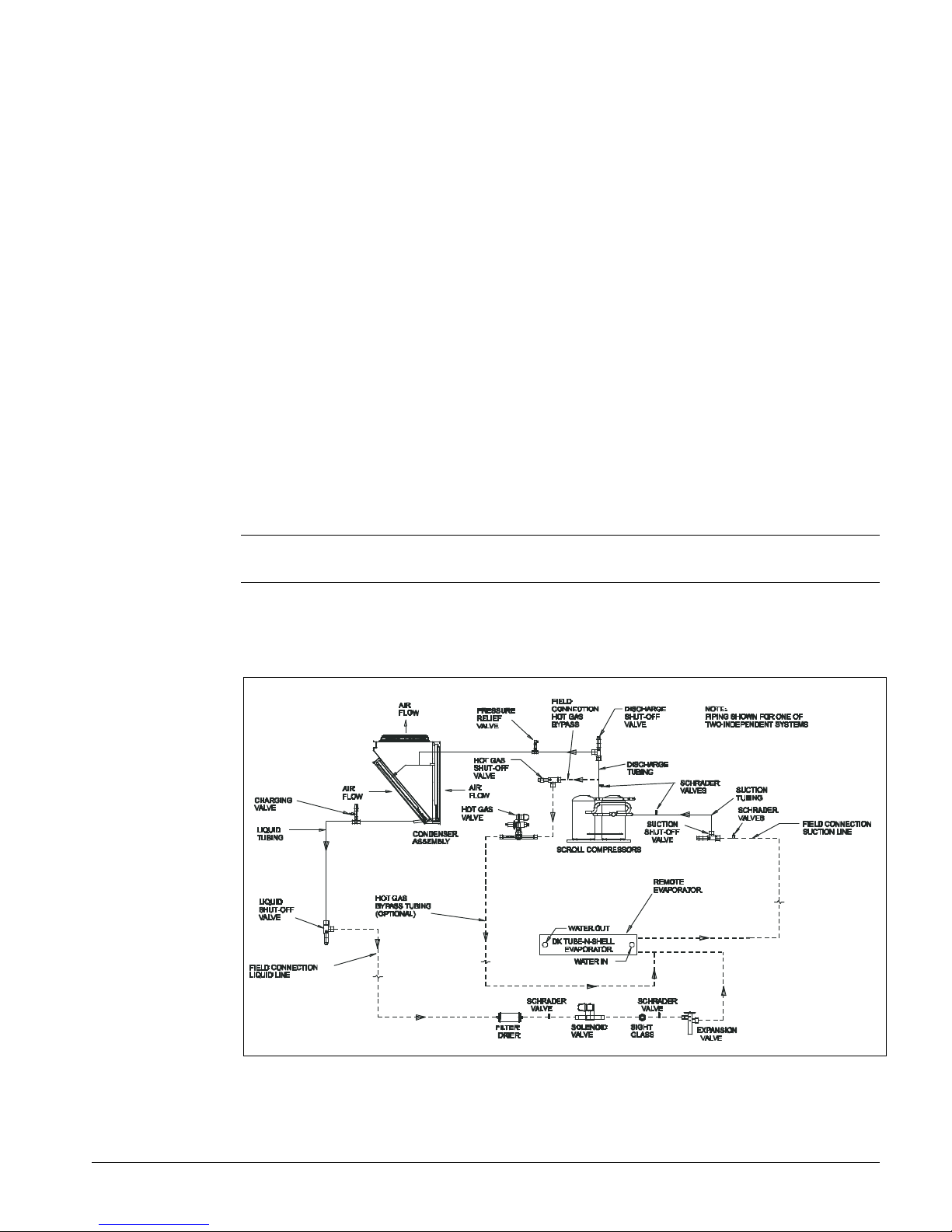
On Model AGZ ---AM units the evaporator is shipped separate for field mounting and piping to the
outdoor unit. The refrigeration piping specialties shown in Figure 1 are furnished and installed by the
installing contractor.
NOTE: A water flow switch or both water flow switch and water pump starter interlock, must be
field installed and wired to protect against evaporator freeze-up under low water flow conditions.
Figure 1, AGZ ---AM Remote Evaporator Piping Schematic (one of two circuits
shown)
Product Manual AGZ-2 AGZ 030A through 065A 5
Page 6

Electrical Control Center
Operating and safety controls and motor starting components are separately housed in a centrally
located, weatherproof control panel with hinged and key locked doors. In addition to one of the three
types of control described in the next sections, the following components are housed in the panel:
• Power terminal block, single point standard
• Control, input, and output terminal block
• Control transformer
• Optional disconnect switch with through-the-door handle
• Compressor contactors (circuit breakers are available as an option) Compressor motor inherent
thermal and overload protection is standard
• Phase voltage monitor with under/over/phase reversal protection
• Fan contactors with separate fuse blocks
• Optional ground fault protection
• The standard FanTrol system controls fan staging for control of refrigerant discharge pressure.
The FanTrol system cycles condenser fans based on discharge pressure and outdoor temperature
and is suited for operation to 40°F (4.4°C).
• The optional SpeedTrol control uses both fan cycling and fan speed control on the lead fan per
circuit and allows operation to 0°F (-18°C) outdoor temperature.
• Mechanical high pressure cutout
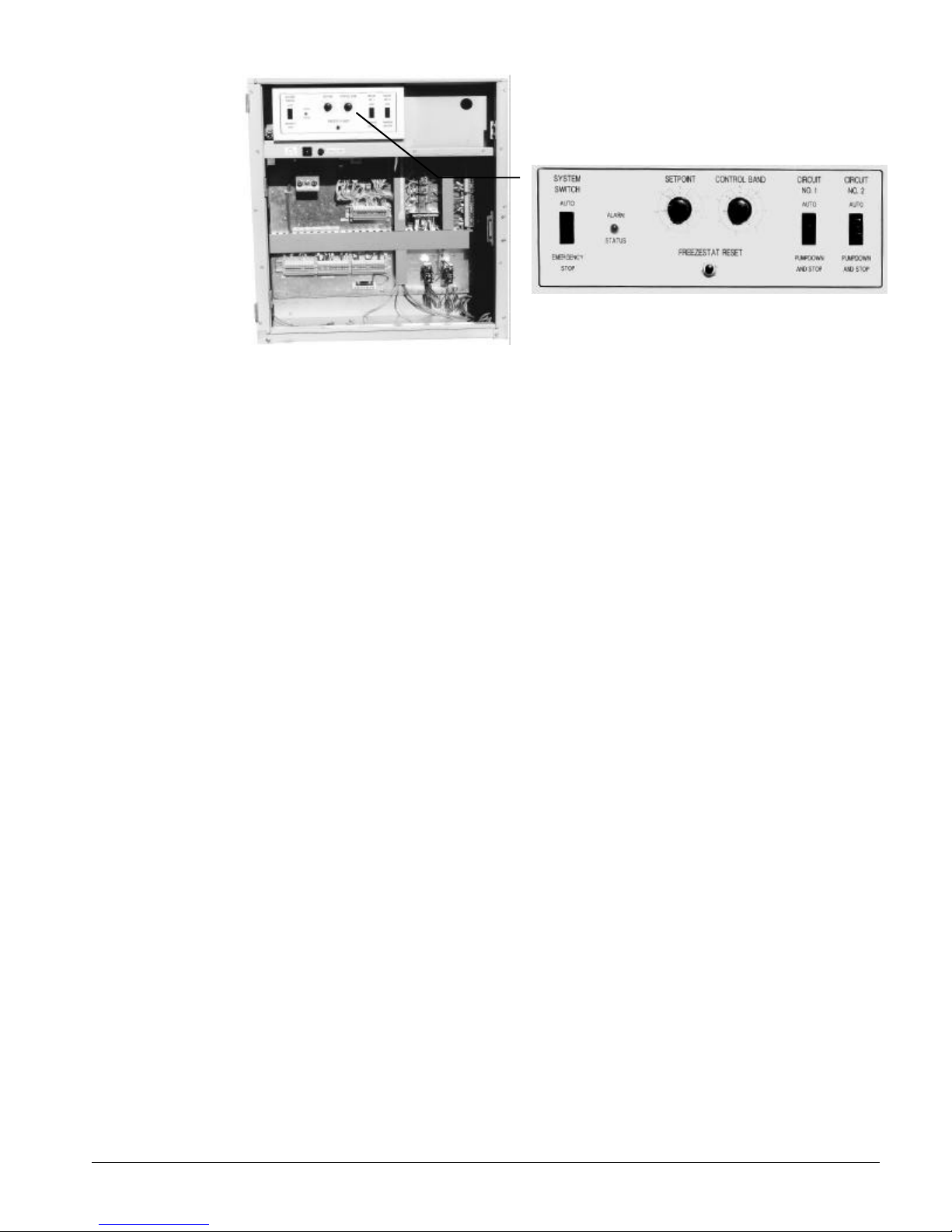
Global UNT Control (Standard)
Microprocessor based control that accomplishes unit capacity control by 4-stage cross-circuit
compressor cycling based on leaving chilled water temperature. Set point and control band are easily
field adjusted. Anti-cycling and stage delay relays are included. Safety controls include low and high
refrigerant pressure, low evaporator flow, sensor failures, and evaporator freeze protection. Motor
protection includes phase voltage, volts ratio, and solid state compressor motor protection. Outside
air reset using a 4-20ma signal is standard. Return water reset, demand limit reset and remote reset
using a 4 to 20 ma signal are available options.
On remote evaporator models AGZ ---AM the leaving chilled water sensor is wired to the unit control
panel and comes with 30 feet (10 m) of cable to enable placing the bulb in the thermowell of the
evaporator. If the distance is greater than 30 feet (10 m), a field splice is required.
Figure 2, Standard Global UNT Controller
6 AGZ 030A through 065A Product Manual AGZ-2
Page 7
Global UNT with Optional Zone Terminal
Provides for onboard (or remotely wired) monitoring or adjusting of certain functions.
• Monitoring
• Monitor up to three setting or sensed values
• Monitor 18 different on/off inputs
• Monitor alarm status via a flashing alarm light and flashing symbol
• Adjusting, allows adjustment of any flashing set points, three at a time, typically set up so that the
relationship between values can be viewed simultaneously. For example
• Display 1 = Lvg Water temp
• Display 2 = Lvg Water SP
• Display 3 = % Unit Load
Product Manual AGZ-2 AGZ 030A through 065A 7
Page 8
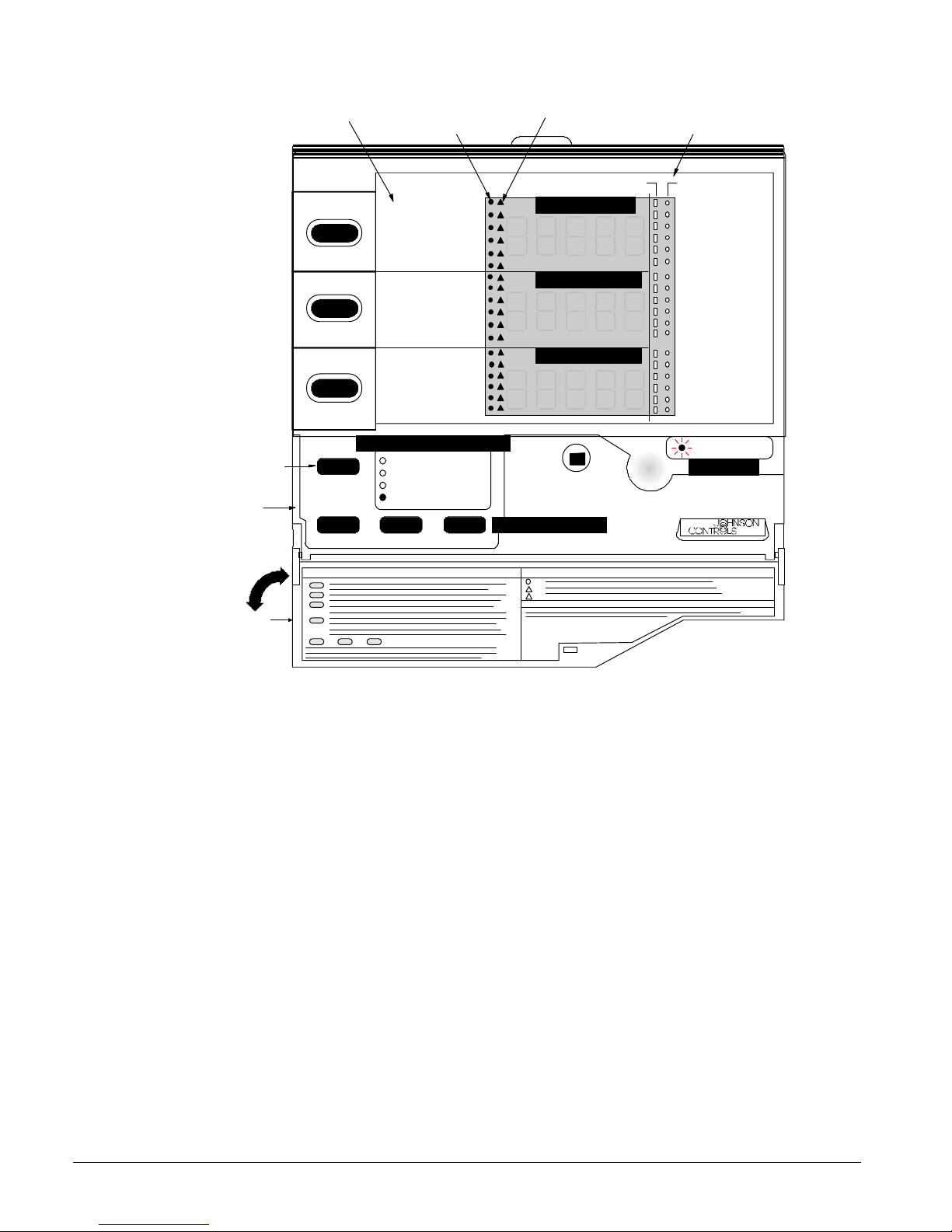
Figure 3, Optional Zone Terminal Configuration
Display Item List
Display Indicator Dot
Warning Signal
On/Off Status
Display
Button 1
Mode
Selector
Button
Mode
Selector
Panel
Door
2
3
McQuay AGZ/AGR Global Chiller
Lvg Water Temp
Evap Pres #1
Eva p Pres #2
OA/AI 3 Input
OA/AI 3 HiLim SP
OA/AI 3 Reset SP
Lvg Water S P
LvgW tr RBnd SP
Cont rl Band SP
Actu al Lvg SP
Unoc cpd Lvg SP
OA Lo ckout S P
% Un it Load
Lvg Low Li m SP
SoftS ta Capc ty
SoftS tart Ti me
Cir # 1 Start s
Cir #2 Star ts
Operatin g Mode Indicato r
MONITOR
ADJUST
TIME SCHEDULE
PASSWORD
ENTER
INSERT 10
Display Area 11
Display Area 21
Display Area 31
Up/Dow n Arrow Keys
ON OFF
Occ upied
Flow Failure
OA L ockout
Cir# 2Lead=On
Pmp/ Stp #1=0
Pmp/S tp #2=0
Solen oid #1
Solen oid #2
Frzs tat#1Alm
Frzs tat#2Alm
MinL owPres#1
MinL owPres#2
Com pressor 1
Com pressor 2
Sta ge 3
Sta ge 4
Stage 5 Opt.
Stag e 6 Opt .
Alarm L ight
ALAR M
AGZ-AGR
8 AGZ 030A through 065A Product Manual AGZ-2
Page 9

MicroTech Control (optional)
Exclusive microprocessor control common throughout McQuay equipment. The interface is a 12 key
keypad and 2-line, 16 character backlit liquid crystal display in plain English. The MicroTech
continuously performs self-diagnostic checks on all system temperatures, pressures, and safeties, and
will automatically shut down a circuit or the entire unit at fault conditions, and close a set of alarm
contacts. The cause, time, and date of the occurrence, as well as important operating conditions, are
recorded and can be displayed by pressing the “Alarm” button.
Enhanced head pressure control logic results in increased SEER during transitional seasons.
Critical shutdown alarms such as high condenser pressure (with mechanical back up), freeze
protection, and low evaporator pressure are manual reset and must be cleared at the keypad to resume
operation.
Tampering is eliminated by use of password protection against unauthorized changing of setpoints and
other control parameters.
An optional modem kit and software package allows remote monitoring and control of the chiller
from an off-site PC via a direct dial telephone line.
Choose the MicroTech control and Open Protocol options to interface with virtually any building
management system and perform remote monitoring and control by hard wiring or modem.
On remote evaporator models AGZ---AM the leaving chilled water sensor is wired to the unit control
panel and comes with 30 feet (10 m) of cable to enable placing the bulb in the thermowell of the
evaporator. If the distance is greater than 30 feet (10 m), a field splice is required.
Figure 4, Optional MicroTech Control Panel
Product Manual AGZ-2 AGZ 030A through 065A 9
Page 10

Selection Procedure
Packaged Chiller, Model AS
Selection with Inch-Pound (I-P) units
Table 9 covers the range of leaving evaporator water temperatures and outside ambient temperatures
included under ARI 550/590-98. The tables are based on a 10 degree F (5.5 degree c) temperature
drop through the evaporator. Adjustment factors for applications having other than a 10 degree F (5.5
degree C) drop can be found in Table 3. The minimum leaving chilled water temperature setpoint
without glycol is 40°F (4°C) . For brine selections, see Table 1 for ethylene or Table 2 for propylene
glycol adjustment factors. Ratings are based on a 0.0001 fouling factor in the evaporator at sea level
operation. For other fouling factors, different delta-Ts, or altitude correction factors see Table 3. For
applications outside the catalog ratings contact your local McQuay sales representative.
Selection example
Given:
50 tons minimum
95°F ambient temperature
120 gpm, 54°F to 44°F chilled water
0.0001 evaporator fouling factor
1. From Performance Table 9, an AGZ 055AS at the given conditions will produce 54.0 tons with a
compressor kW input of 59.0 and a unit EER of 9.9.
2. Use the following formula to calculate any unknown elements.
tons°×
F
3. Determine the evaporator pressure drop. Using Figure 8, enter at 120 gpm and follow up to the
AGZ 055AS line intersect. Read horizontally to obtain an evaporator pressure drop of 14.0 feet
of water.
24
gpm =
Selection example using ethylene glycol
Given:
45 tons minimum
95°F ambient air temperature
54°F - 44°F chilled water temperature
0.0001 evaporator fouling factor
Protect from freezing down to 0°F
1. From Table 1, select an ethylene glycol concentration of 40% to protect against freezing at 0°F.
2. At 40% ethylene glycol, the adjustment factors are: Capacity =0.961, kW = 0.976,
GPM = 1.121, pressure drop = 1.263
3. Select the AGZ 050AS and correct with 40% ethylene glycol factors.
4. Correct capacity = 0.961 X 49.0 tons = 47.1 tons
5. Correct compressor kW = 0.976 X 52.6 kW = 51.3 kW
6. Calculate chilled water flow:
241.47
tons°×
= capacity) corrected(at flowWater
10
F
Glycol flow (at 40% solution) = 1.121 X 113.0 gpm = 126.2 gpm
gpm 113.0 =
10 AGZ 030A through 065A Product Manual AGZ-2
Page 11

Determine the evaporator pressure drop. Using Figure 8, enter at 112.6 gpm (water) and follow up to
the AGZ 050AS line intersect. Read horizontally to obtain an evaporator pressure drop of 12.3 feet.
The pressure drop for 40% solution = 1.263 X 12.3 feet = 15.5 feet for ethylene glycol.
Selection with SI units
Table 10 covers a range of leaving evaporator water temperatures and outside ambient temperatures.
The tables are based on a 5°C temperature drop through the evaporator. The minimum leaving chilled
water temperature setpoint without glycol is 4.5°C. For brine selections, see Table 1 for ethylene or
Table 2 for propylene glycol adjustment factors. Ratings are based on a 0.0176 fouling factor in the
evaporator at sea level operation. For other fouling factors, derates for different Delta-Ts, or altitude
correction factors see Table 3. For applications outside the catalog ratings contact your local McQuay
sales representative.
Selection example
Given:
190 kW minimum
35°C ambient air temperature
9 L/s, 12°C - 7°C chilled water
0.0176 evaporator fouling factor
1. From Table 10, an AGZ 055AS at the given conditions will produce 192.8 kW with a unit kW
input of 59.4 and a COP of 3.0.
2. Use the following formula to calculate any missing elements:
L/s
3. Determine the evaporator pressure drop. Using Figure 8, enter at 9.0 L/s and follow down to the
kW
18.4=°× C
AGZ 055AS line intersect. Read horizontally to obtain an evaporator pressure drop of 54.0 kPa.
Selection example using ethylene glycol
Given: 161 kW minimum
35°C ambient air temperature
12°C - 7°C chilled water temperature
0.0176 evaporator fouling factor
Protect against freezing down to -18°C
1. From Table 1, select an ethylene glycol concentration of 40% to protect against freezing.
2. At 40% ethylene glycol, the adjustment factors are: Capacity = 0.961, kW = 0.976,
GPM = 1.121, pressure drop = 1.263
3. Select the AGZ 050AS and from Table 10with 40% ethylene glycol factors.
4. Correct capacity = 0.961 X 175.1 kW = 168.3 kW
5. Correct compressor kW = 0.976 X 52.8 kW = 51.5 kW
6. Calculate chilled water flow:
3.168
Water flow (at corrected capacity) = L/s 8
Glycol flow (at 40% solution) = 1.121 X 8 L/s = 9 L/s
7. Determine the evaporator pressure drop. Using Figure 8, enter at 9 L/s and follow up to the
AGZ 050As line intersect. Read horizontally to obtain an evaporator pressure drop of 50.0 kPa.
The pressure drop for 40% solution = 1.263 X 50.0 kPa = 63.1 kPa
kW
518.4
°× C
=
Product Manual AGZ-2 AGZ 030A through 065A 11
Page 12

Remote Evaporator, Model AM
Inch-Pound (I-P) Units
Since the AGZ-AM units always include a remote specific shell and tube heat exchanger, the ratings are
based on leaving chilled water temperature and ambient air temperature.
Table 9 (English) and Table 10 (SI) cover performance over the normal range of leaving chilled water
temperatures and outside ambient air temperatures. The tables are based on a 10°F (5.0°C)
temperature drop through the evaporator. Adjustment factors for other temperature drops can be
found in Table 3. The minimum leaving chilled water temperature setpoint without glycol is 40°F
(4.4°C). For brine selections, see Table 1 for ethylene or Table 2 for propylene glycol adjustment
factors. Ratings are based on a 0.0001 (0.0176) fouling factor in the evaporator at sea level operation.
For other fouling factors, derates for different delta-Ts, or altitude, see Table 3. For applications
outside the catalog ratings contact your local McQuay sales representative.
The length and configuration of the field installed interconnecting refrigerant piping will affect the
system capacity. Derates based on equivalent length of line are given in Table 8.
The steps for selecting an AGZ-AM are as follows:
1. Add 3% to the required cooling capacity (to approximate correction factors) and make a
preliminary unit selection from performance Table 9 through Error! Reference source not
found..
2. Divide the required capacity by the appropriate capacity correction factors: glycols from Table 1or
Table 2, altitude, chilled water Delta T, or fouling factor from Table 3; and refrigerant piping
derate from Table 8 as explained in step 3 below.
3. Determine the suction line size by first summing the equivalent feet (from Table 4) of all the
fittings (use a sketch of the piping layout) and adding the sum of these fitting losses to the actual
linear feet of tubing. This will then equal the total equivalent feet. (To use the equivalent feet
Table 4, start with the unit suction connection size from Table 6 as the first try). Now, knowing
the equivalent feet and the unit size, check the line selection in Table 6 or Table 7 and correct if
required.
4. If the unit rated capacity in the tables is less than the corrected required capacity, redo the selection
with the next larger unit. In most cases the line size will be the unit connection size. If the
selection is satisfactory, correct the power (if applicable) and determine water pressure drop.
Selection example
English Units
Given:
42 tons required capacity
95°F ambient temperature
Cool 100 gpm from 54°F to 44°F
0.0001 evaporator fouling factor
2,000 foot altitude
Figure 5, Sample Piping Layout
12 AGZ 030A through 065A Product Manual AGZ-2
Page 13

1. Add 3% to the required capacity for approximate derate: 42 x 1.03 = 43.3 tons. From
Performance Table 9 an AGZ-045AM at the given conditions will produce 44.3 tons with a
compressor kW input of 46.9 and a unit EER of 10.0.
2. Determine derate factors:
Altitude correction from Table 3; 0.986 Capacity, 1.009 Power
3. Piping correction:
Assume 1 5/8” suction line based on connection size in Table 6, from Table 4
(3) 90° Standard ells 3 x 4 ft =12 ft
Plus actual linear feet 70 ft
Total Equivalent Feet 82 ft
Check Table 7 for size and find that 1 5/8” is minimum size for oil carry.
This means that the 1 5/8 riser will be satisfactory.
The capacity correction factor from Table 8 is 0.980.
4. The corrected capacity of the AGZ is: 44.3 tons x 0.986{altitude} x 0.98{piping} = 42.8 tons
This satisfies the 42 ton requirement.
5. Correct the compressor power required: 46.9 kW x 1.009{altitude} = 47.3 kW.
6. Calculate the unit power input from corrected EER:
W = BTU / EER W = 42.8 tons x 12 mbh / (10.1EER / 1.009) = 50.4 kW
7. Determine the evaporator pressure drop. Enter the pressure drop curves (Figure 8) at 100 gpm
and read up to AGZ 045AM, read over to pressure drop of 10.2 ft.
Selection example using ethylene glycol
Given: 40 tons minimum
95°F ambient air temperature
54°F - 44°F chilled water temperature
0.0001 evaporator fouling factor
Protect from freezing down to 0°F
1. From Table 1, select an ethylene glycol concentration of 40% to protect against freezing at 0°F.
2. At 40% ethylene glycol, the adjustment factors are: Capacity =0.961, kW = 0.976,
gpm = 1.121, pressure drop = 1.263
3. Select the AGZ-045AM and correct with 40% ethylene glycol factors.
4. Correct capacity = 0.961 X 44.3 tons = 42.6 tons
5. Correct compressor kW = 0.976 X 46.9 = 45.8 kW
6. Calculate chilled water flow:
246.42
tons°×
= capacity) corrected(at flowWater
10
F
Glycol flow (at 40% solution) = 1.121 X 102.2 gpm = 114.6 gpm
Determine the evaporator pressure drop. Using Figure 8, enter at 102.2 gpm (water) and follow up to
the AGZ-045AM line intersect. Read horizontally to obtain an evaporator pressure drop of 10.5 feet.
The pressure drop for 40% solution = 1.263 X 10.5 feet = 13.3 feet for ethylene glycol.
Correct for refrigerant piping pressure drop using Table 8. Assuming 150 equivalent feet, the
corrected capacity is 0.971 X 42.6 = 41.4 tons.
gpm 102.2 =
Selection example, SI Units
The selection procedure for Metric units is identical to English except that metric data and tables are
used.
Product Manual AGZ-2 AGZ 030A through 065A 13
Page 14
Application Adjustment Factors
Ethylene and Propylene Glycol Factors
AGZ units can operate with a leaving chilled fluid temperature range of 20°F (-6°C) to 50°F (10°C).
A glycol solution is required when leaving chilled fluid temperature is below 40°F (4.6°C). The use
of glycol will reduce the performance of the unit depending on concentration.
Altitude Correction Factors
Performance tables are based at sea level. Elevations other than sea level affect the performance of the
unit. The decreased air density will reduce condenser capacity consequently reducing the unit's
performance. For performance at elevations other than sea level refer to Table 3.
Evaporator Temperature Drop Factors
Performance tables are based on a 10°F (5°C) temperature drop through the evaporator. Adjustment
factors for applications with temperature ranges from 6°F to 16°F (3.3°C to 8.9°C) are in Table 3.
Temperature drops outside this 6°F to 16°F (3.3°C to 8.9°C) range may affect the control system's
capability to maintain acceptable control and are not recommended.
The maximum water temperature that can be circulated through the evaporator in a non-operating
mode is 100°F (37.8°C).
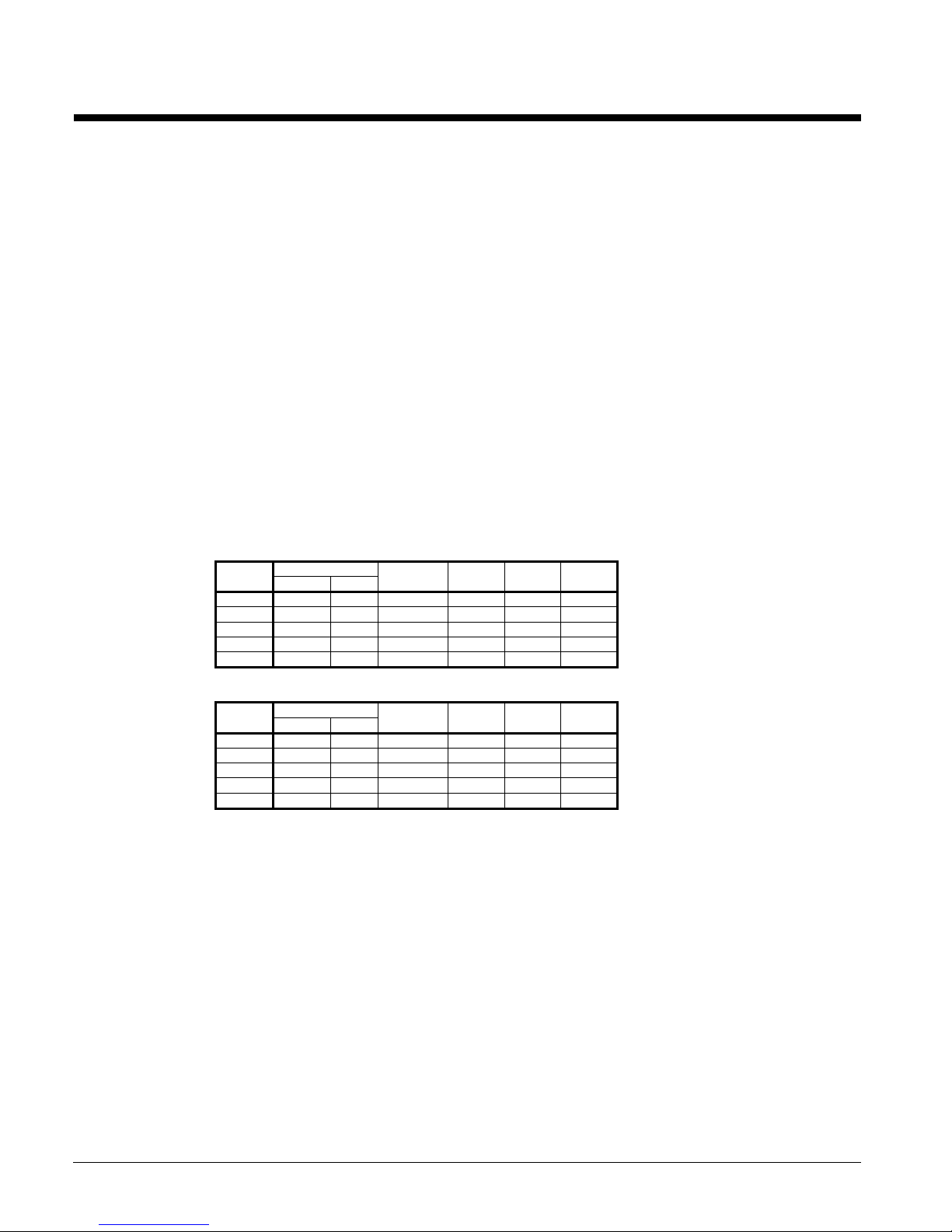
Table 1, Ethylene Glycol
% Freeze Point
E.G. °F °C Capacity Power Flow PD
10 26 -3 0.991 0.996 1.013 1.070
20 18 -8 0.982 0.992 1.040 1.129
30 7 -14 0.972 0.986 1.074 1.181
40 -7 -22 0.961 0.976 1.121 1.263
50 -28 -33 0.946 0.966 1.178 1.308
Table 2, Propylene Glycol
% Freeze Point
P.G. °F °C Capacity Power Flow PD
10 26 -3 0.987 0.992 1.010 1.068
20 19 -7 0.975 0.985 1.028 1.147
30 9 -13 0.962 0.978 1.050 1.248
40 -5 -21 0.946 0.971 1.078 1.366
50 -27 -33 0.929 0.965 1.116 1.481
NOTE: Ethylene and propylene glycol ratings are outside the scope of
ARI Standard 550/590-98 certification program
Fouling Factor
Performance tables are based on water with a fouling factor of
performance decreases. For performance at other than 0.0001 (0.0176) fouling factor refer to Table
3.
Foreign matter in the chilled water system will adversely affect the heat transfer capability of the
evaporator, and could increase the pressure drop and reduce the water flow. To ensure optimum unit
operation, maintain proper water treatment.
22
)/0176.0(,,/0001.0
kWCmorBTUFhrft °×°×× per ARI 550/590-98. As fouling is increased,
14 AGZ 030A through 065A Product Manual AGZ-2
Page 15
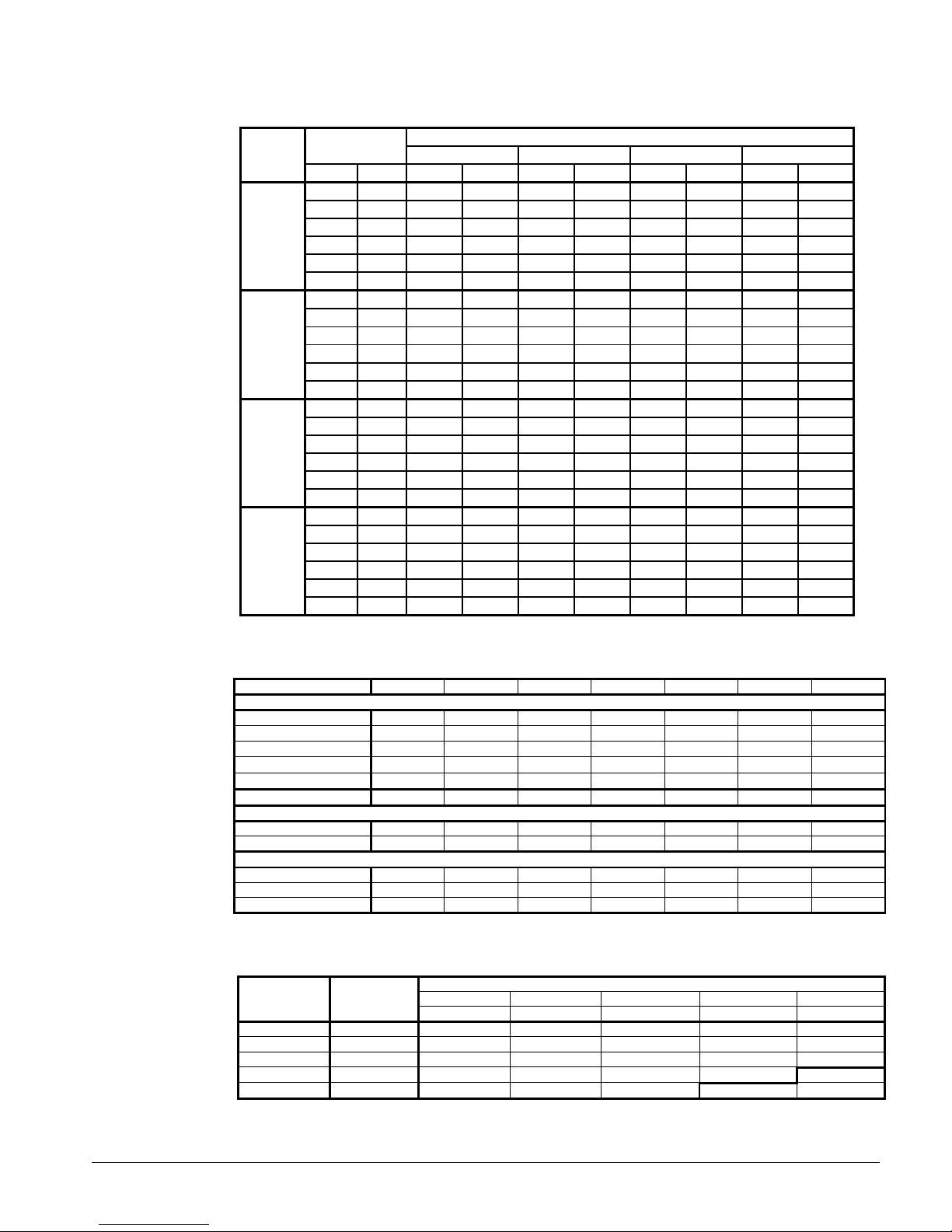
Table 3, Capacity and Power Derates
Chilled Water Fouling Factor
Delta-T 0.0001 (0.0176) 0.00025 (0.044) 0.00075 (0.132) 0.00175 (0.308)
ALTITUDE °F °C Cap. Power Cap. Power Cap. Power Cap. Power
6 3.3 0.992 0.995 0.985 0.993 0.962 0.986 0.919 0.972
8 4.4 0.995 0.997 0.988 0.995 0.965 0.988 0.922 0.974
SEA 10 5.6 1.000 1.000 0.993 0.998 0.970 0.991 0.927 0.977
LEVEL 12 6.7 1.005 1.002 0.998 1.000 0.975 0.993 0.932 0.979
14 6.8 1.010 1.005 1.003 1.003 0.980 0.996 0.936 0.982
16 8.9 1.014 1.007 1.007 1.005 0.984 0.998 0.940 0.984
6 3.3 0.978 1.005 0.971 1.003 0.949 0.996 0.906 0.982
8 4.4 0.982 1.007 0.975 1.005 0.953 0.998 0.910 0.984
2000 feet 10 5.6 0.986 1.009 0.979 1.007 0.956 1.000 0.914 0.986
(610 m) 12 6.7 0.992 1.011 0.985 1.009 0.962 1.002 0.919 0.988
14 6.8 0.997 1.014 0.990 1.012 0.967 1.005 0.924 0.991
16 8.9 1.000 1.016 0.993 1.014 0.970 1.007 0.927 0.993
6 3.3 0.966 1.016 0.959 1.014 0.937 1.007 0.895 0.993
8 4.4 0.969 1.018 0.962 1.016 0.940 1.009 0.898 0.995
4000 feet 10 5.6 0.973 1.021 0.966 1.019 0.944 1.012 0.902 0.998
(1220 m) 12 6.7 0.978 1.025 0.971 1.023 0.949 1.016 0.906 1.002
14 6.8 0.982 1.027 0.975 1.025 0.953 1.018 0.910 1.004
16 8.9 0.986 1.028 0.979 1.026 0.956 1.019 0.914 1.005
6 3.3 0.953 1.025 0.946 1.023 0.924 1.016 0.883 1.002
8 4.4 0.955 1.028 0.948 1.026 0.926 1.019 0.885 1.005
6000 feet 10 5.6 0.959 1.031 0.952 1.029 0.930 1.022 0.889 1.008
(1830 m) 12 6.7 0.963 1.034 0.956 1.032 0.934 1.024 0.893 1.011
14 6.8 0.968 1.036 0.961 1.034 0.939 1.026 0.897 1.013
16 8.9 0.972 1.037 0.965 1.035 0.943 1.027 0.901 1.014
Table 4, Equivalent Feet for Fittings
Fitting Type 7/8 1 1/8 1 3/8 1 5/8 2 1/8 2 5/8 3 1/8
Elbows
90°° Standard
90°° Long Radius
90°° Street
45°° Standard
45°° Street
180°° Bend
Tees
Full Size 1.4 1.7 2.3 2.6 3.3 4.1 5.0
Reducing 2.0 2.6 3.3 4.0 5.0 6.0 7.5
Valves
Globe Valve, Open 22 29 38 43 55 69 84
Gate Valve, Open 0.9 1.0 1.5 1.8 2.3 2.8 3.2
Angle Valve, Open 9.0 12 15 18 24 29 35
2.0 2.6 3.3 4.0 5.0 6.0 7.5
1.4 1.7 2.3 2.6 3.3 4.1 5.0
3.2 4.1 5.6 6.3 8.2 10 12
0.9 1.3 1.7 2.1 2.6 3.2 4.0
1.5 2.1 3.0 3.4 4.5 5.2 6.4
3.2 4.1 5.6 6.3 8.2 10 12
Table 5, Recommended Liquid Line Size
Unit Model Size Up to Up to Up to Up to Up to
AGZ030AM 7/8" 7/8 " 7/8 " 7/8 " 7/8 " 7/8 "
AGZ035AM 7/8" 7/8 " 7/8 " 7/8 " 7/8 " 7/8 "
AGZ040AM 7/8" 7/8 " 7/8 " 7/8 " 7/8 " 7/8 "
AGZ045AM 7/8" 7/8 " 7/8 " 7/8 " 7/8 " 1 1/8 "
AGZ050AM 7/8" 7/8 " 7/8 " 7/8 " 1 1/8 " 1 1/8 "
Connection Recommended Liquid Line Size
At Unit 50 Equiv. Ft 75 Equiv. Ft 100 Equiv. Ft 125 Equiv. Ft 150 Equiv. Ft
Product Manual AGZ-2 AGZ 030A through 065A 15
Page 16
Table 6, Recommended Horizontal or Downflow Suction Line Size
Unit Model Size Up to Up to Up to Up to Up to
AGZ030AM 1 5/8" 1 5/8" 1 5/8" 1 5/8" 1 5/8" 2 1/8"
AGZ035AM 1 5/8" 1 5/8" 1 5/8" 2 1/8" 2 1/8" 2 1/8"
AGZ040AM 1 5/8" 1 5/8" 1 5/8" 2 1/8" 2 1/8" 2 1/8"
AGZ045AM 1 5/8" 1 5/8" 2 1/8" 2 1/8" 2 1/8" 2 1/8"
AGZ050AM 1 5/8" 1 5/8" 2 1/8" 2 1/8" 2 1/8" 2 1/8"
Note: For horizontal and vertical downflow only
Connection Recommended Suction Line Sizes
At Unit 50 Equiv. Ft 75 Equiv. Ft 100 Equiv. Ft 125 Equiv. Ft 150 Equiv. Ft
Table 7, Minimum Line Size (R-22) For Oil Carry Up a Suction Riser
Unit Size OD AGZ 030 AGZ 035 AGR 040 AGZ 045 AGZ 050
Line Size 1 5/8 1 5/8 1 5/8 1 5/8 1 5/8
Table 8, Refrigerant Piping Derates
Unit Model Capacity Loss Factor Due to Refrigerant Piping
AGZ030AM 1.0 0.984 0.975 0.966 0.957 0.987
AGZ035AM 1.0 0.973 0.960 0.987 0.984 0.981
AGZ040AM 1.0 0.971 0.957 0.984 0.980 0.976
AGZ045AM 1.0 0.957 0.985 0.980 0.975 0.971
AGZ050AM 1.0 0.957 0.981 0.975 0.969 0.962
At Unit 50 Equiv. Ft 75 Equiv. Ft 100 Equiv. Ft 125 Equiv. Ft 150 Equiv. Ft
16 AGZ 030A through 065A Product Manual AGZ-2
Page 17

Performance Data
Table 9, AGZ 030AS through 065AS, Packaged, Standard Efficiency
AGZ 030AM through 050AM, Remote Evaporator
NOTE: ARI Certified only when used as an AGZ ---AS, Packaged Unit
AGZ LWT 75°F 85°F 95°F 105°F 115°F
SIZE (°F) Cap. PWR Cap. PWR Cap. PWR Cap. PWR Cap. PWR
Tons kWi EER Tons kWi EER Tons kWi EER Tons kWi EER Tons kWi EER
40.0 31.3 24.7 12.9 29.9 27.8 11.2 28.5 31.1 9.5 27.1 35.0 8.3 25.6 39.2 7.0
42.0 32.3 24.8 13.2 31.0 27.8 11.5 29.6 31.3 9.8 28.1 35.0 8.5 26.6 39.2 7.2
030AS 44.0 33.4 24.9 13.6 32.0 28.0 11.8 30.6 31.4 10.1 29.1 35.3 8.8 27.5 39.4 7.4
030AM 46.0 34.5 25.1 14.0 33.1 28.1 12.2 31.7 31.6 10.4 30.1 35.4 9.0 28.5 39.7 7.7
48.0 35.7 25.1 14.4 34.2 28.3 12.5 32.7 31.6 10.7 31.1 35.5 9.3 29.4 39.8 7.9
50.0 36.9 25.3 14.8 35.4 28.3 12.9 33.8 31.8 11.0 32.1 35.7 9.6 30.4 40.0 8.1
40.0 34.9 28.4 12.8 33.3 31.9 11.1 31.8 35.8 9.4 30.1 40.2 8.2 28.5 45.0 7.0
42.0 36.0 28.5 13.1 34.5 32.0 11.4 33.0 36.0 9.7 31.3 40.3 8.4 29.6 45.1 7.2
035AS 44.0 37.2 28.7 13.4 35.6 32.2 11.7 34.1 36.1 10.0 32.4 40.5 8.7 30.7 45.3 7.4
035AM 46.0 38.5 28.8 13.8 36.9 32.3 12.1 35.3 36.3 10.3 33.5 40.7 8.9 31.7 45.6 7.6
48.0 39.8 28.9 14.2 38.2 32.5 12.4 36.5 36.4 10.6 34.6 40.8 9.2 32.8 45.8 7.8
50.0 41.1 29.1 14.6 39.4 32.6 12.8 37.7 36.6 10.9 35.8 41.1 9.5 33.8 46.0 8.0
40.0 39.7 32.7 12.8 37.9 36.7 11.1 36.2 41.1 9.4 34.3 46.2 8.2 32.4 51.8 7.0
42.0 41.0 32.7 13.1 39.3 36.8 11.4 37.5 41.3 9.7 35.6 46.3 8.4 33.7 51.8 7.2
040AS 44.0 42.3 33.0 13.4 40.5 37.0 11.7 38.8 41.5 10.0 36.9 46.6 8.7 34.9 52.1 7.4
040AM 46.0 43.8 33.1 13.8 42.0 37.1 12.1 40.2 41.7 10.3 38.1 46.8 8.9 36.1 52.4 7.6
48.0 45.3 33.2 14.2 43.4 37.4 12.4 41.5 41.8 10.6 39.4 46.9 9.2 37.3 52.6 7.8
50.0 46.8 33.4 14.6 44.9 37.4 12.8 42.9 42.1 10.9 40.7 47.2 9.5 38.5 52.9 8.0
40.0 45.2 37.1 12.5 43.4 41.3 11.0 41.5 46.2 9.5 39.3 51.8 8.2 37.1 58.2 6.9
42.0 46.8 37.4 12.9 44.9 41.6 11.3 42.9 46.5 9.8 40.7 52.2 8.4 38.4 58.6 7.1
045AS 44.0 48.5 37.8 13.2 46.4 42.0 11.6 44.3 46.9 10.0 42.0 52.5 8.7 39.6 59.0 7.3
045AM 46.0 50.1 38.1 13.6 48.0 42.3 11.9 45.9 47.2 10.3 43.3 52.9 8.8 40.8 59.5 7.4
48.0 51.9 38.3 13.9 49.7 42.6 12.2 47.4 47.6 10.5 44.7 53.3 9.0 41.9 59.8 7.6
50.0 53.6 38.7 14.3 51.1 43.0 12.6 48.6 47.9 10.8 45.9 53.7 9.3 43.0 60.3 7.7
40.0 50.0 41.6 12.5 48.0 46.3 11.0 45.9 51.8 9.5 43.5 58.1 8.2 41.1 65.3 6.9
42.0 51.8 42.0 12.9 49.6 46.7 11.3 47.5 52.2 9.8 45.0 58.5 8.4 42.4 65.8 7.1
050AS 44.0 53.6 42.3 13.2 51.3 47.1 11.6 49.0 52.6 10.0 46.4 58.9 8.7 43.8 66.2 7.3
050AM 46.0 55.5 42.7 13.6 53.1 47.4 11.9 50.7 53.0 10.3 47.9 59.3 8.8 45.1 66.7 7.4
48.0 57.4 43.0 13.9 54.9 47.8 12.2 52.4 53.3 10.5 49.4 59.8 9.0 46.3 67.1 7.6
50.0 59.2 43.4 14.3 56.5 48.2 12.6 53.8 53.7 10.8 50.7 60.2 9.3 47.6 67.6 7.7
40.0 55.1 46.6 12.4 52.9 51.9 10.9 50.6 58.1 9.4 48.0 65.2 8.1 45.3 73.2 6.8
42.0 57.1 47.1 12.7 54.7 52.3 11.2 52.3 58.5 9.7 49.6 65.7 8.4 46.8 73.8 7.0
055AS 44.0 59.1 47.5 13.1 56.5 52.8 11.5 54.0 59.0 9.9 51.1 66.0 8.6 48.3 74.3 7.2
46.0 61.1 47.9 13.4 58.5 53.2 11.8 55.9 59.4 10.1 52.8 66.5 8.8 49.7 74.9 7.4
48.0 63.2 48.2 13.8 60.5 53.6 12.1 57.8 59.8 10.4 54.4 67.1 8.9 51.0 75.2 7.5
50.0 65.3 48.7 14.2 62.3 54.1 12.4 59.3 60.3 10.7 55.9 67.5 9.2 52.4 75.8 7.6
40.0 58.7 51.8 12.0 56.3 57.7 10.6 53.9 64.6 9.1 51.1 72.5 7.9 48.2 81.4 6.6
42.0 60.8 52.3 12.3 58.2 58.2 10.8 55.7 65.1 9.4 52.8 73.0 8.1 49.8 82.0 6.8
060AS 44.0 62.9 52.8 12.7 60.2 58.7 11.1 57.5 65.6 9.6 54.5 73.4 8.3 51.4 82.6 7.0
46.0 65.1 53.3 13.0 62.3 59.1 11.4 59.5 66.1 9.8 56.2 73.9 8.5 52.9 83.2 7.1
48.0 67.3 53.6 13.4 64.5 59.6 11.7 61.5 66.5 10.1 58.0 74.6 8.7 54.3 83.6 7.3
50.0 69.5 54.1 13.7 66.4 60.2 12.0 63.1 67.0 10.4 59.5 75.0 8.9 55.8 84.3 7.4
40.0 62.2 54.1 12.3 59.7 60.3 10.8 57.2 67.5 9.3 54.2 75.7 8.0 51.1 85.0 6.8
42.0 64.5 54.7 12.6 61.8 60.8 11.1 59.1 68.0 9.6 56.0 76.2 8.3 52.8 85.6 7.0
065AS 44.0 66.7 55.1 12.9 63.9 61.3 11.4 61.0 68.5 9.8 57.8 76.7 8.5 54.5 86.2 7.2
46.0 69.1 55.6 13.3 66.1 61.7 11.7 63.1 69.0 10.0 59.7 77.2 8.7 56.1 86.9 7.3
48.0 71.4 56.0 13.7 68.4 62.2 12.0 65.3 69.5 10.3 61.5 77.9 8.9 57.6 87.3 7.4
50.0 73.7 56.5 14.0 70.4 62.8 12.3 67.0 70.0 10.6 63.1 78.4 9.1 59.2 88.0 7.5
NOTES:
1. "AM", remote evaporator ratings do not include line loss. See selection procedure.
2. Bold ratings certified in accordance with ARI Standard 550/590-98 for "AS" units only.
3. Ratings based on HCFC-22, evaporator fouling of 0.0001, 2.4 gpm/ton, and sea level altitude.
4. Ratings are based on circuit #1 in lead position and circuit #2 in lag position.
5. Interpolation is allowed; extrapolation is not permitted. Consult McQuay for performance outside the cataloged ratings.
6. KWi input is for compressors only. EER is for the entire unit, including compressors, fan motors and control power.
7. For LWT below 40°F and below please refer to Application Data.
AMBIENT AIR TEMPERATURE
Product Manual AGZ-2 AGZ 030A through 065A 17
Page 18

Table 10, 030AS through 065AS, Standard Efficiency, SI Units
AGZ 030AM through 050AM, Remote Evaporator
AMBIENT AIR TEMPERATURE
AGZ LWT 25oC (77oF) 30oC (86oF) 35oC (95oF) 40oC (104oF) 45oC (113oF)
SIZE (oC) Cap. PWR Cap. PWR Cap. PWR Cap. PWR Cap. PWR
5.0 (41.0oF) 111.5 25.3 3.6 106.7 28.2 3.2 102.3 31.2 2.8 97.3 34.6 2.4 92.3 38.2 2.1
6.0 (42.8oF) 115.2 25.5 3.7 110.8 28.2 3.3 105.8 31.3 2.9 100.8 34.7 2.5 95.3 38.4 2.2
030AS 7.0 (44.6oF) 119.3 25.5 3.9 114.6 28.3 3.4 109.6 31.4 3.0 104.1 34.9 2.6 98.8 38.6 2.2
030AM 8.0 (46.4oF) 121.2 25.6 3.9 116.5 28.4 3.4 111.5 31.5 3.0 106.1 34.9 2.6 100.5 38.8 2.3
9.0 (48.2oF) 125.4 25.7 4.0 120.4 28.5 3.5 115.2 31.7 3.1 109.6 35.1 2.7 104.1 38.9 2.3
10.0 (50.0oF) 129.8 25.9 4.1 124.4 28.6 3.6 119.1 31.8 3.2 113.3 35.3 2.8 107.7 39.1 2.4
5.0 (41.0oF) 124.1 29.1 3.6 118.8 32.4 3.2 113.9 35.9 2.8 108.3 39.8 2.4 102.7 44.0 2.1
6.0 (42.8oF) 128.3 29.3 3.7 123.4 32.5 3.3 117.8 36.0 2.9 112.2 40.0 2.5 106.2 44.2 2.2
035AS 7.0 (44.6oF) 132.9 29.4 3.9 127.6 32.6 3.4 122.0 36.2 3.0 116.0 40.1 2.6 110.0 44.4 2.2
035AM 8.0 (46.4oF) 135.0 29.5 3.9 129.7 32.7 3.4 124.1 36.3 3.0 118.1 40.2 2.6 111.8 44.6 2.3
9.0 (48.2oF) 139.6 29.6 4.0 134.0 32.8 3.5 128.3 36.4 3.1 122.0 40.4 2.7 116.0 44.8 2.3
10.0 (50.0oF) 144.5 29.8 4.1 138.5 33.0 3.6 132.6 36.6 3.2 126.2 40.6 2.8 119.9 45.0 2.4
5.0 (41.0oF) 141.0 33.4 3.6 135.0 37.2 3.2 129.4 41.2 2.8 123.1 45.7 2.4 116.7 50.5 2.1
6.0 (42.8oF) 145.7 33.7 3.7 140.1 37.3 3.3 133.8 41.3 2.9 127.5 45.9 2.5 120.6 50.7 2.2
040AS 7.0 (44.6oF) 150.9 33.7 3.9 144.9 37.4 3.4 138.6 41.5 3.0 131.7 46.0 2.6 125.0 51.0 2.2
040AM 8.0 (46.4oF) 153.3 33.9 3.9 147.3 37.5 3.4 141.0 41.6 3.0 134.2 46.1 2.6 127.1 51.2 2.3
9.0 (48.2oF) 158.6 33.9 4.0 152.2 37.7 3.5 145.7 41.8 3.1 138.6 46.3 2.7 131.7 51.4 2.3
10.0 (50.0oF) 164.2 34.2 4.1 157.4 37.8 3.6 150.6 42.0 3.2 143.4 46.6 2.8 136.3 51.6 2.4
5.0 (41.0oF) 160.9 38.2 3.6 154.9 42.0 3.2 148.4 46.5 2.8 141.6 51.6 2.4 134.1 57.2 2.1
6.0 (42.8oF) 166.6 38.5 3.7 159.9 42.4 3.3 153.6 46.9 2.9 146.2 51.8 2.5 138.2 57.7 2.2
045AS 7.0 (44.6oF) 172.3 38.8 3.8 165.8 42.6 3.4 158.6 47.2 3.0 150.9 52.3 2.6 142.5 58.0 2.2
045AM 8.0 (46.4oF) 175.3 38.9 3.9 168.5 42.8 3.4 161.2 47.4 3.0 153.6 52.5 2.6 145.0 58.2 2.2
9.0 (48.2oF) 180.9 39.2 4.0 173.9 43.2 3.5 166.7 47.7 3.1 158.3 52.8 2.7 149.4 58.7 2.3
10.0 (50.0oF) 187.3 39.4 4.1 179.9 43.6 3.6 172.1 48.0 3.2 163.5 53.2 2.7 154.2 59.1 2.4
5.0 (41.0oF) 177.6 42.7 3.6 170.9 47.0 3.2 163.8 52.0 2.8 156.3 57.7 2.4 148.0 64.0 2.1
6.0 (42.8oF) 183.9 43.0 3.7 176.5 47.4 3.3 169.5 52.4 2.9 161.4 58.0 2.5 152.6 64.5 2.2
050AS 7.0 (44.6oF) 190.2 43.4 3.8 183.0 47.7 3.4 175.1 52.8 3.0 166.6 58.4 2.6 157.2 64.9 2.2
050AM 8.0 (46.4oF) 193.4 43.5 3.9 186.0 47.9 3.4 177.9 53.0 3.0 169.5 58.7 2.6 160.0 65.1 2.2
9.0 (48.2oF) 199.7 43.9 4.0 192.0 48.3 3.5 183.9 53.3 3.1 174.7 59.1 2.7 164.9 65.6 2.3
10.0 (50.0oF) 206.7 44.1 4.1 198.6 48.7 3.6 189.9 53.7 3.2 180.4 59.5 2.7 170.2 66.0 2.4
5.0 (41.0oF) 195.6 48.0 3.6 188.2 52.9 3.2 180.4 58.5 2.8 172.1 64.9 2.4 163.0 72.0 2.1
6.0 (42.8oF) 202.5 48.4 3.7 194.4 53.3 3.3 186.7 59.0 2.9 177.8 65.2 2.5 168.0 72.5 2.2
055AS 7.0 (44.6oF) 209.4 48.8 3.8 201.5 53.6 3.4 192.8 59.4 3.0 183.5 65.8 2.6 173.2 73.0 2.2
8.0 (46.4oF) 213.1 48.9 3.9 204.8 53.9 3.4 195.9 59.6 3.0 186.7 66.0 2.6 176.3 73.2 2.2
9.0 (48.2oF) 219.9 49.4 4.0 211.4 54.3 3.5 202.6 60.0 3.1 192.4 66.5 2.7 181.7 73.8 2.3
10.0 (50.0oF) 227.7 49.6 4.1 218.7 54.8 3.6 209.2 60.4 3.2 198.7 67.0 2.7 187.4 74.3 2.4
5.0 (41.0oF) 209.2 53.3 3.5 201.4 58.8 3.1 193.0 65.0 2.7 184.1 72.2 2.3 174.4 80.0 2.0
6.0 (42.8oF) 216.6 53.8 3.6 208.0 59.2 3.2 199.8 65.5 2.8 190.2 72.5 2.4 179.8 80.6 2.1
060AS 7.0 (44.6oF) 224.1 54.2 3.7 215.6 59.6 3.2 206.3 66.0 2.9 196.3 73.1 2.5 185.3 81.1 2.1
8.0 (46.4oF) 227.9 54.3 3.7 219.2 59.9 3.3 209.6 66.2 2.9 199.8 73.3 2.5 188.6 81.3 2.1
9.0 (48.2oF) 235.3 54.9 3.8 226.2 60.3 3.4 216.7 66.6 2.9 205.8 73.8 2.6 194.4 82.0 2.2
10.0 (50.0oF) 243.6 55.1 3.9 234.0 60.9 3.5 223.8 67.1 3.1 212.6 74.4 2.6 200.5 82.6 2.3
5.0 (41.0oF) 220.3 55.7 3.5 212.0 61.4 3.1 203.2 67.9 2.7 193.9 75.4 2.3 183.6 83.5 2.0
6.0 (42.8oF) 228.1 56.2 3.6 218.9 61.9 3.2 210.3 68.4 2.8 200.3 75.7 2.4 189.3 84.2 2.1
065AS 7.0 (44.6oF) 235.9 56.6 3.7 227.0 62.3 3.2 217.2 69.0 2.9 206.7 76.3 2.5 195.1 84.7 2.1
8.0 (46.4oF) 240.0 56.8 3.7 230.7 62.5 3.3 220.7 69.2 2.9 210.3 76.6 2.5 198.5 84.9 2.1
9.0 (48.2oF) 247.7 57.3 3.8 238.2 63.0 3.4 228.2 69.6 2.9 216.7 77.1 2.6 204.6 85.7 2.2
10.0 (50.0oF) 256.4 57.6 3.9 246.4 63.6 3.5 235.6 70.1 3.1 223.8 77.7 2.6 211.1 86.2 2.3
NOTES:
1. Ratings based on HCFC-22, evaporator fouling of 0.0176, 0.048 L/s, and sea level altitude.
2. Ratings are based on circuit #1 in lead position and circuit #2 in lag position.
3. Interpolation is allowed; extrapolation is not permitted. Consult McQuay for performance outside the cataloged ratings.
4. KWi input is for compressors only. COP is for the entire unit, including compressors, fan motors and control power.
5. For LWT below 4.5°C and below please refer to Application Data.
kW kWi COP kW kWi COP kW kWi COP kW kWi COP kW kWi COP
18 AGZ 030A through 065A Product Manual AGZ-2
Page 19

Part Load Data
Table 11, AGZ 030AS through 065AS
60 Hz
Unit Size % Load Capacity Power
Tons Unit kW EER IPLV
100.00 30.6 36.4 10.1
030AS 75.00 22.9 22.3 12.3 13.5
50.00 15.3 13.1 14.0
25.00 7.6 5.8 15.7
100.00 34.1 41.1 10.0
035AS 75.00 25.5 24.7 12.4 13.8
50.00 17.0 14.1 14.5
25.00 8.5 6.3 16.2
100.00 38.8 46.5 10.0
040AS 75.00 29.1 27.6 12.7 14.2
50.00 19.4 15.5 15.0
25.00 9.7 6.9 16.9
100.00 44.3 53.1 10.0
045AS 75.00 33.2 31.7 12.6 13.8
50.00 22.1 18.4 14.4
25.00 11.0 8.2 16.1
100.00 49.0 58.8 10.0
050AS 75.00 36.7 35.3 12.5 14.0
50.00 24.5 19.9 14.8
25.00 12.2 8.9 16.4
100.00 54.0 65.2 9.9
055AS 75.00 40.4 37.9 12.8 14.1
50.00 26.9 21.7 14.9
25.00 13.4 10.0 16.1
100.00 57.5 71.9 9.6
060AS 75.00 43.2 41.5 12.5 14.1
50.00 28.8 22.6 15.3
25.00 14.4 11.0 15.7
100.00 61.0 74.7 9.8
065AS 75.00 45.7 43.0 12.8 14.5
50.00 30.4 23.3 15.7
25.00 15.0 11.0 16.4
Certified according to ARI Standard 550/590-98
Product Manual AGZ-2 AGZ 030A through 065A 19
Page 20

Sound Data
Table 12, AGZ 030-065 Sound Pressure
Unit .Octave Band at Center Frequency Overall
Model 63 125 250 500 1000 2000 4000 8000 A-Weighted
AGZ030AS 65 64 63 61 56 51 46 41 61
AGZ035AS 65 64 63 61 56 51 46 41 61
AGZ040AS 65 64 63 62 57 52 47 42 62
AGZ045AS 66 66 64 62 58 52 47 42 63
AGZ050AS 67 67 66 62 58 53 48 43 63
AGZ055AS 67 67 67 63 59 54 49 44 64
AGZ060AS 68 68 67 64 60 54 49 44 65
AGZ065AS 68 68 67 64 61 55 50 45 65
AGZ030AM 65 64 63 61 56 51 46 41 61
AGZ035AM 65 64 63 61 56 51 46 41 61
AGZ040AM 65 64 63 62 57 52 47 42 62
AGZ045AM 66 66 64 62 58 52 47 42 63
AGZ050AM 67 67 66 62 58 53 48 43 63
Note: Data at 30 feet (9m) from side of unit.
Table 13, AGZ 030-065 Sound Power
Unit Octave Band at Center Frequency. Overall
Model 63 125 250 500 1000 2000 4000 8000 A-Weighted
AGZ030AS 92 91 90 88 83 78 73 68 88
AGZ035AS 92 91 90 88 83 78 73 68 88
AGZ040AS 92 91 90 89 84 79 74 69 89
AGZ045AS 93 93 91 89 85 79 74 69 90
AGZ050AS 94 94 93 89 85 80 75 70 90
AGZ055AS 94 94 94 90 86 81 76 71 91
AGZ060AS 95 95 94 91 87 81 76 71 92
AGZ065AS 95 95 94 91 88 82 77 72 92
AGZ030AM 92 91 90 88 83 78 73 68 88
AGZ035AM 92 91 90 88 83 78 73 68 88
AGZ040AM 92 91 90 89 84 79 74 69 89
AGZ045AM 93 93 91 89 85 79 74 69 90
AGZ050AM 94 94 93 89 85 80 75 70 90
Note: Sound power octave band data per ARI Standard 370
Sound levels are as important as unit cost and efficiency, and must be addressed before to the start of
any development program. Efforts by McQuay Design Engineers to design chillers that are sensitive to
the sound requirements of the market, combined with inherently quiet scroll compressors, have paid
off.
Background Information
Sound is a vibration in an elastic medium and is essentially a pressure and particle displacement
phenomena. A vibrating body produces compression waves and as the waves are emitted from the
vibrating body, molecules are ultimately compressed. These values are transmitted through gas, liquid,
solid-anything which is elastic or viscous.
The sound data provided in this section is presented with both sound pressure and sound power levels.
Sound power is the total sound energy radiated by a source per unit of time integrated over the surface
through which the sound is radiated. Sound power is a calculated quantity and cannot be measured
directly like sound pressure. Sound power is not dependent on the surrounding environment or
distance from the source, as is sound pressure.
Sound pressure varies with the distance from the source and is dependent on its surroundings. For
example, a brick wall located 10 feet from a unit will affect the sound pressure measurements
differently than a brick wall at 20 feet. Sound pressure is measured in decibels (dB), which is a
dimensionless ratio (on a logarithmic scale) between measured sound pressure and a reference sound
pressure level.
20 AGZ 030A through 065A Product Manual AGZ-2
Page 21

Sound Pressure Levels - Full Load
All sound pressure tables give the overall "A" weighted sound pressure levels which are considered
typical of what may be measured in a free field with a hand held sound meter, in the absence of any
nearby reflective surfaces. The sound pressure levels are measured at 30 feet (10 meters) from the side
of the unit at 100% unit load and ARI conditions. 95°F (35°C) ambient air temperature and 54/44°F
(12/7°C) evaporator water temperatures for air-cooled units.
Sound Power Levels
Acoustical consultants may require sound power octave band data to perform a detailed acoustical
analysis. The tables present sound power levels per ARI Standard 370, “Sound Rating of Large
Outdoor Refrigerating and Air Conditioning Equipment”. These standards were developed to establish
uniform methods of determining the sound power radiated by large outdoor and indoor equipment.
The aforementioned methods are based on providing sound power levels by octave band and the
overall ‘A’ weighted value. Measurements are taken over a prescribed area around the unit and the data
is mathematically calculated to give the sound power, dB.
Sound Reduction due to Distance from the Unit
The distance between a source of sound and the location of the sound measurement plays an important
role in minimizing sound problems. The equation below can be used to calculate the sound pressure
level at any distance if the sound power is known.
Sound pressure can be calculated at any distance from the unit if the sound power is known.
Lp=Lw-(20 log r) + (10 log Q) - .5
Lp = sound pressure
Lw = sound power
r = distance from unit in feet
Q = directionality factor
The directionality factor is a dimensionless number that compensates for the type of sound radiation
from the source. Figure 6 shows the typical Q values of different reflecting surfaces.
For a unit sitting on a flat roof with no other reflective surfaces or attenuation due to grass, snow, etc.,
between source and receiver: Q=2.
With Q=2, the equation simplifies to:
Lp = Lw - (20)(log r) + 2.5
Figure 6, "Q" Values
Uniform Spherical Radiation Uniform Hemispherical Radiation Uniform Radiation over 1/4 of sphere
Q=1 no reflecting surface Q=2 single reflecting surface Q=4 two reflecting surfaces
Product Manual AGZ-2 AGZ 030A through 065A 21
Page 22

Unit Orientation to Minimize Sound
The chiller’s sound is directional in nature allowing the contractor/engineer to position the unit to
minimize potential noise problems. Because the sound pressure levels are lower at both ends of the
unit than at the sides, the chiller should be oriented such that the control box end or end opposite the
control box faces the direction where the lowest sound level is required.
The control box end provides an excellent acoustic barrier to the compressor sound as it covers one
full end of the unit. The sound pressure levels at the control box end will be 4 dBA less than on the
sides.
Figure 7, Sound Directionality
Sound Pressure Levels - Low Ambient Operation
Unit operation at a lower ambient temperature than 95°F (35°C) will also result in lower sound
pressure levels. The sound pressure level will decrease 1 dBA for ambient temperatures between 85°F
and 94°F (29.4°C and 34.4°C), 2 dBA for ambient temperatures between 75°F and 84°F (23.9°C and
28.9°C), and 3 dBA for ambient temperatures between 65°F and 74°F (18.3°C and 23.3°C).
22 AGZ 030A through 065A Product Manual AGZ-2
Page 23

Pressure Drop Curves
045A-060A
065A
Figure 8, Pressure Drops
030A-040A
AGZ NOMINAL MAXIMUM MINIMUM
Unit Pressure Drop Flow Pressure Drop Flow Pressure Drop Flow
Size (ft) of Water (gpm) (lps) (ft) of Water (gpm) (lps) (ft) of Water (gpm) (lps)
030AS/AM 7.4 73 4.61 18.7 122 7.68 3.2 46 2.88
035AS/AM 9.2 82 5.17 23.1 137 8.62 3.9 51 3.23
040AS/AM 11.5 93 5.87 28.8 155 9.78 4.9 58 3.67
045AS/AM 11.2 106 6.69 28.2 177 11.15 4.8 66 4.18
050AS 13.4 117 7.38 33.6 195 12.30 5.7 73 4.61
050AM 13.6 118 7.44 34.1 197 12.41 5.8 74 4.65
055AS 16.2 129 8.14 40.0 215 13.56 7.0 81 5.09
060AS 18.0 138 8.71 45.0 230 14.51 7.7 86 5.44
065AS 10.0 146 9.21 25.1 243 15.35 4.3 91 5.76
Product Manual AGZ-2 AGZ 030A through 065A 23
Page 24

Electrical Data
Table 14, AGZ 030A - 065A, 60 Hz, Single Point Power Electrical Data
AGZ
Unit Size
030AS 230 131 3 1/0 1 1.50 (38) 150
030AM 380 86 3 3 1 1.25 (32) 100
030AS 230 143 3 1/0 1 1.50 (38) 150
035AM 380 93 3 3 1 1.25 (32) 110
040AS 230 159 3 2/0 1 1.50 (38) 175
040AM 380 111 3 2 1 1.25 (32) 125
045AS 230 183 3 3/0 1 2.00 (51) 200
045AM 380 116 3 1 1 1.25 (32) 125
050AS 230 198 3 3/0 1 2.00 (51) 225
050AM 380 120 3 1 1 1.25 (32) 125
055As 380 138 3 1/0 1 1.50 (38) 150
060AS 380 153 3 2/0 1 1.50 (38) 175
065AS 380 153 3 2/0 1 1.50 (38) 175
All Electrical Data notes are on page 27
Minimum POWER SUPPLY
Volts
208 131 3 1/0 1 1.50 (38) 150
460 68 3 4 1 1.00 (25) 80
575 53 3 6 1 1.00 (25) 60
208 143 3 1/0 1 1.50 (38) 150
460 73 3 4 1 1.00 (25) 80
575 58 3 6 1 1.00 (25) 70
208 159 3 2/0 1 1.50 (38) 175
460 78 3 4 1 1.00 (25) 90
575 67 3 4 1 1.00 (25) 80
208 183 3 3/0 1 2.00 (51) 200
460 94 3 3 1 1.25 (32) 110
575 76 3 4 1 1.00 (25) 90
208 198 3 3/0 1 2.00 (51) 225
460 104 3 2 1 1.25 (32) 125
575 83 3 4 1 1.00 (25) 100
208 214 3 4/0 1 2.00 (51) 250
230 214 3 4/0 1 2.00 (51) 250
460 109 3 2 1 1.25 (32) 125
575 92 3 3 1 1.25 (32) 110
208 228 3 4/0 1 2.50 (64) 300
230 228 3 4/0 1 2.50 (64) 300
460 112 3 2 1 1.25 (32) 125
575 100 3 3 1 1.25 (32) 110
208 228 3 4/0 1 2.50 (64) 300
230 228 3 4/0 1 2.50 (64) 300
460 112 3 2 1 1.25 (32) 125
575 100 3 3 1 1.25 (32) 110
Circuit Field Wire Hub
Ampacity
(MCA)
Quantity
Wire
Gauge
Quantity
Nominal
Size
Max. Fuse
Or HACR
Breaker
Size
24 AGZ 030A through 065A Product Manual AGZ-2
Page 25

Table 15, AGZ 030A - 065A, 60 Hz, Compressor And Condenser Fan Motor Amp
Draw
AGZ Compressors No. Of Compressors
Unit Volts No. No. Fan Across-The-Line
Size 1 & 3 2 & 4 Motors No.1 & 3 No.2 & 4
208 23.7 29.9 4.0 4 17.0 189 232
030AS 230 23.7 29.9 4.0 4 17.0 189 232
030AM 380 14.9 18.6 3.4 4 14.4 112 144
460 12.5 15.3 2.0 4 8.5 94 125
575 9.1 11.6 2.2 4 10.3 74 100
208 29.9 29.9 4.0 4 17.0 232 232
230 29.9 29.9 4.0 4 17.0 232 232
035AS 380 18.6 18.6 3.4 4 14.4 144 144
035AM 460 15.3 15.3 2.0 4 8.5 125 125
575 11.6 11.6 2.2 4 10.3 100 100
208 33.6 33.6 4.0 4 17.0 278 278
040AS 230 33.6 33.6 4.0 4 17.0 278 278
040AM 380 22.8 22.8 3.4 4 14.4 151 151
460 16.5 16.5 2.0 4 8.5 127 127
575 13.7 13.7 2.2 4 10.3 100 100
208 33.6 41.0 5.8 4 23.7 278 350
230 33.6 41.0 5.8 4 23.7 278 350
045AS 380 22.8 25.0 3.4 4 14.4 151 195
045AM 460 16.5 21.8 2.8 4 10.7 127 158
575 13.7 17.3 2.3 4 11.5 100 125
208 41.0 41.0 5.8 4 23.7 350 350
050AS 230 41.0 41.0 5.8 4 23.7 350 350
050AM 380 25.0 25.0 3.4 4 14.4 195 195
460 21.8 21.8 2.8 4 10.7 158 158
575 17.3 17.3 2.3 4 11.5 125 125
208 41.0 48.1 5.8 4 23.7 350 425
230 41.0 48.1 5.8 4 23.7 350 425
055AS 380 25.0 32.7 3.4 4 14.4 195 239
460 21.8 23.7 2.8 4 10.7 158 187
575 17.3 21.2 2.3 4 11.5 125 148
208 48.1 48.1 5.8 4 23.7 425 425
230 48.1 48.1 5.8 4 23.7 425 425
060AS 380 32.7 32.7 3.4 4 14.4 239 239
460 23.7 23.7 2.8 4 10.7 187 187
575 21.2 21.2 2.3 4 11.5 148 148
208 48.1 48.1 5.8 4 23.7 425 425
230 48.1 48.1 5.8 4 23.7 425 425
065AS 380 32.7 32.7 3.4 4 14.4 239 239
460 23.7 23.7 2.8 4 10.7 187 187
575 21.2 21.2 2.3 4 11.5 148 148
All Electrical Data notes are on page 27
Rated Load Amps Locked Rotor Amps
(Each) (Each)
Fan
Motors
(Each)
Fan
Motors
(Each)
(Each) (Each)
Product Manual AGZ-2 AGZ 030A through 065A 25
Page 26

Table 16, AGZ 030A - 065A, 60 Hz Single Point Power, Field Wiring Data
AGZ
Unit
Size
030AS 230 335 # 4 - 400 MCM 225 # 3 - 300 MCM
030AM 380 175 #12 - 2/0 100 #14 - 1/0
035AS 380 175 #12 - 2/0 100 #14 - 1/0
035AM 460 175 #12 - 2/0 100 #14 - 1/0
040AS 230 335 # 4 - 400 MCM 225 # 3 - 300 MCM
040AM 380 175 #12 - 2/0 150 #4 - 4/0
045AS 380 175 #12 - 2/0 150 #4 - 4/0
045AM 460 175 #12 - 2/0 100 #14 - 1/0
050AS 230 335 # 4 - 400 MCM 225 # 3 - 300 MCM
050AM 380 335 # 4 - 400 MCM 150 #4 - 4/0
055AS 380 335 # 4 - 400 MCM 250 #4 - 350 MCM
060AS 380 335 # 4 - 400 MCM 250 #4 - 350 MCM
065AS 380 335 # 4 - 400 MCM 250 #4 - 350 MCM
All Electrical Data notes are on page 27
Volts
208 335 # 4 - 400 MCM 225 # 3 - 300 MCM
460 175 #12 - 2/0 100 #14 - 1/0
575 175 #12 - 2/0 100 #14 - 1/0
208 335 # 4 - 400 MCM 225 # 3 - 300 MCM
230 335 # 4 - 400 MCM 225 # 3 - 300 MCM
575 175 #12 - 2/0 100 #14 - 1/0
208 335 # 4 - 400 MCM 225 # 3 - 300 MCM
460 175 #12 - 2/0 100 #14 - 1/0
575 175 #12 - 2/0 100 #14 - 1/0
208 335 # 4 - 400 MCM 225 # 3 - 300 MCM
230 335 # 4 - 400 MCM 225 # 3 - 300 MCM
575 175 #12 - 2/0 100 #14 - 1/0
208 335 # 4 - 400 MCM 225 # 3 - 300 MCM
460 175 #12 - 2/0 150 #4 - 4/0
575 175 #12 - 2/0 150 #4 - 4/0
208 335 # 4 - 400 MCM 400 250 - 500 MCM
230 335 # 4 - 400 MCM 400 250 - 500 MCM
460 175 #12 - 2/0 150 #4 - 4/0
575 175 #12 - 2/0 150 #4 - 4/0
208 335 # 4 - 400 MCM 400 250 - 500 MCM
230 335 # 4 - 400 MCM 400 250 - 500 MCM
460 175 #12 - 2/0 150 #4 - 4/0
575 175 #12 - 2/0 150 #4 - 4/0
208 335 # 4 - 400 MCM 400 250 - 500 MCM
230 335 # 4 - 400 MCM 400 250 - 500 MCM
460 175 #12 - 2/0 150 #4 - 4/0
575 175 #12 - 2/0 150 #4 - 4/0
Wiring to Standard Wiring to Optional
Power Block Non-Fused Disconnect Switch
Terminal Connector Wire Range Terminal Connector Wire Range
Amps (Copper Wire Only) Amps (Copper Wire Only)
26 AGZ 030A through 065A Product Manual AGZ-2
Page 27

Notes for “Electrical Data Single Point” Power:
1. Unit wire size ampacity (MCA) is equal to 125% of the largest compressor-motor RLA plus
100% of RLA of all other loads in the circuit including the control transformer.
2. If the control transformer option is furnished, no separate 115V power is required.
3. If a separate 115V power supply is used for the control circuit, then the wire sizing amps is 10
amps for all unit sizes.
4. Recommended power lead wire sizes for 3 conductors per conduit are based on 100% conductor
ampacity in accordance with NEC. Voltage drop has not been included. Therefore, it is
recommended that power leads be kept short. All terminal block connections must be made with
copper (type THW) wire.
5. “Recommended Fuse Sizes” are selected at approximately 150% to 175% of the largest
compressor RLA, plus 100% of all other loads in the circuit.
6. “Maximum Fuse or HACR breaker size” is selected at approximately 225% of the largest
compressor RLA, plus 100% of all other loads in the circuit.
7. The recommended power lead wire sizes are based on an ambient temperature of 86°F (30°C).
Ampacity correction factors must be applied for other ambient temperatures. Refer to the
National Electrical Code Handbook.
8. Must be electrically grounded according to national and local electrical codes.
9. MCA may vary slightly due to fan motor options such as SpeedTrol, TEFC.
Voltage Limitations:
Within ± 10 percent of nameplate rating
Notes for “Compressor and Condenser Fan Amp Draw”:
1. Compressor RLA values are for wiring sizing purposes only but do not reflect normal operating
current draw at rated capacity. If unit is equipped with SpeedTrol condenser fan motors, the first
motor on each refrigerant circuit is a single phase, 1hp motor, with a FLA of 2.8 amps at 460
volts, 5.6 amps at 208, 230, and 575 volts.
2. Compressor LRA for reduced inrush start are for the first winding only. If the unit is equipped
with SpeedTrol motors, the first motor is a single phase, 1 hp motor, with a LRA of 7.3 amps at
460 volts, 14.5 amps at 208, 230, and 575 volts.
Notes for “Field Wiring Data”
1. Requires a single disconnect to supply electrical power to the unit. This power supply must either
be fused or use an HACR type circuit breaker.
2. All field wiring to unit power block or optional non-fused disconnect switch must be copper.
3. All field wire size values given in table apply to 75°C rated wire per NEC.
Product Manual AGZ-2 AGZ 030A through 065A 27
Page 28

Figure 9, Typical Field Wiring with MicroTech Controller
See Note 3 for “Electrical Data Single Point Power” on page 27
28 AGZ 030A through 065A Product Manual AGZ-2
Page 29

Figure 10, Typical Field Wiring Diagram with UNT Controller
See note 3 for “Electrical Data Single Point Power” on page 27
Product Manual AGZ-2 AGZ 030A through 065A 29
Page 30

Physical Data
AGZ-AS
Table 17, AGZ 030AS Through 045AS
STANDARD EFFICIENCY 030AS 035AS 040AS 045AS
BASIC DATA Ckt.1 Ckt.2 Ckt.1 Ckt.2 Ckt.1 Ckt.2 Ckt.1 Ckt.2
Unit Capacity @ ARI Conditions (1), Tons (kW) 30.8 (108.4) 34.1 (120.0) 38.8 (136.6) 44.3 (156.0)
Number Of Refrigerant Circuits 2 2 2 2
Unit Operating Charge, R-22, Lbs. 34 34 36 36 40 40 42 42
Unit Operating Charge, R-22, (kg) (15.4) (15.4) (16.3) (16.3) (18.1) (18.1) (19.0) (19.0)
Cabinet Dimensions, LxWxH, In. 94.0 x 88.2 x 86.2 94.0 x 88.2 x 86.2 94.0 x 88.2 x 86.2 94.0 x 88.2 x 86.2
Cabinet Dimensions, LxWxH, (mm) 2388 x 2241 x 2190 2388 x 2241 x 2190 2388 x 2241 x 2190 2388 x 2241 x 2190
Unit Operating Weight, Lb (kg) 3425 (1555) 3480 (1580) 3535 (1605) 3800 (1725)
Unit Shipping Weight, Lb (kg) 3350 (1520) 3405 (1545) 3460 (1570) 3695 (1675)
Add'l Weight If Copper Finned Coils, Lb (kg) 445 (200) 445 (200) 445 (200) 445 (200)
COMPRESSORS
Nominal tonnage of each Compressor 7.5 9.0 9.0 9.0 10.0 10.0 10.0 13.0
Number Of Compressors per Circuit 2 2 2 2 2 2 2 2
Oil Charge Per Compressor, Oz. 140 140 140 140 140 140 140 140
Oil Charge Per Compressor, (g) (496) (496) (496) (496) (496) (496) (496) (496)
CAPACITY REDUCTION STEPS - PERCENT OF COMPRESSOR DISPLACEMENT
Standard Staging - Circuit #1 in Lead
Standard Staging - Circuit #2 in Lead
CONDENSERS - HIGH EFFICIENCY FIN AND TUBE TYPE WITH INTEGRAL SUBCOOLING
Coil Face Area,Sq. Ft. 46.4 46.4 46.4 46.4 46.4 46.4 46.4 46.4
Coil Face Area, (M2) (4.3) (4.3) (4.3) (4.3) (4.3) (4.3) (4.3) (4.3)
Finned Height x Finned Length, In. 80 x 83.5 80 x 83.5 80 x 83.5 80 x 83.5 80 x 83.5 80 x 83.5 80 x 83.5 80 x 83.5
Finned Height x Finned Length, (mm) 2032 x
Fins Per Inch x Rows Deep 16 x 2 16 x 2 16 x 2 16 x 2 16 x 2 16 x 2 16 x 2 16 x 2
Pumpdown Capacity, 90% Full Lbs. (kg) 63 (28.6) 63 (28.6) 63 (28.6) 63 (28.6) 63 (28.6) 63 (28.6) 63 (28.6) 63 (28.6)
Maximum Relief Valve Pressure Setting, psig (kPa) 450
CONDENSER FANS - DIRECT DRIVE PROPELLER TYPE
Number Of Fans - Fan Diameter, In. (mm) 4 - 28 (712) 4 - 28 (712) 4 - 28 (712) 4 - 28 (712)
Number Of Motors - HP (kW) (2) 4 - 1.0 (0.7) 4 - 1.0 (0.7) 4 - 1.0 (0.7) 4 - 1.5 (1.1)
Fan And Motor RPM, 60Hz 1140 1140 1140 1140
60 Hz Fan Tip Speed, FPM (M/Sec) 8357 (35.4) 8357 (35.4) 8357 (35.4) 8357 (35.4)
60 Hz Total Unit Airflow, CFM (M3/sec) 34400 (16.2) 34400 (16.2) 34400 (16.2) 38000 (17.9)
DIRECT EXPANSION EVAPORATOR - BAFFLED SHELL AND THRU-TUBE
Diameter, in. - Length, Ft. 10 - 04 10 - 04 10 - 04 12 - 04
Diameter, (mm) - Length, (mm) (254) - (1220) (254) - (1220) (254) - (1220) (305) - (1220)
Water Volume, Gallons, (L) 9.1 (34.5) 9.1 (34.5) 9.1 (34.5) 12.8 (48.5)
Maximum Water Pressure, psig (kPa) 175 (1207) 175 (1207) 175 (1207) 175 (1207)
Maximum Refrigerant Working Pressure, psig
Water Inlet / Outlet Victaulic Connections, In. (mm) 4 (101.6) 4 (101.6) 4 (101.6) 4 (101.6)
Drain - NPT int, In. (mm) .375 (9.5) .375 (9.5) .375 (9.5) .375 (9.5)
Vent - NPT int, In. (mm) .375 (9.5) .375 (9.5) .375 (9.5) .375 (9.5)
NOTES:
1. Nominal capacity based on 95°F ambient air and 54°F/44°F water range.
2. Units with 1.0 Hp Fan Motors, Uses 1.5 Hp Fan Motors when unit is 380V / 60 Hz and 575V / 60Hz.
PHYSICAL DATA AGZ MODEL NUMBER
Type Tandem Scrolls Tandem Scrolls Tandem Scrolls Tandem Scrolls
Standard 4 Stages 0-23-50-73-100 0-25-50-75-100 0-25-50-75-100 0-22-50-72-100
Standard 4 Stages 0-27-50-77-100 0-25-50-75-100 0-25-50-75-100 0-28-50-78-100
(kPa)
2121
(3103)
2032 x
2121
450
(3103)
225 (1552) 225 (1552) 225 (1552) 225 (1552)
2032 x
2121
450
(3103)
2032 x
2121
450
(3103)
2032 x
2121
450
(3103)
2032 x
2121
450
(3103)
2032 x
2121
450
(3103)
2032 x
2121
450
(3103)
30 AGZ 030A through 065A Product Manual AGZ-2
Page 31

Table 18, AGZ050AS Through 065AS
PHYSICAL DATA AGZ MODEL NUMBER
STANDARD EFFICIENCY 050AS 055AS 060AS 065AS
BASIC DATA Ckt.1 Ckt.2 Ckt.1 Ckt.2 Ckt.1 Ckt.2 Ckt.1 Ckt.2
COMPRESSORS
CAPACITY REDUCTION STEPS - PERCENT OF COMPRESSOR DISPLACEMENT
CONDENSERS - HIGH EFFICIENCY FIN AND TUBE TYPE WITH INTEGRAL SUBCOOLING
CONDENSER FANS - DIRECT DRIVE PROPELLER TYPE
DIRECT EXPANSION EVAPORATOR - BAFFLED SHELL AND THRU-TUBE
NOTE: Nominal capacity based on 95°F ambient air and 54°F/44°F water range.
Unit Capacity @ ARI Conditions (1), Tons (kW) 49.0 (172.5) 54.0 (190.1) 57.5 (202.2) 61.0 (214.7)
Number Of Refrigerant Circuits 2 2 2 2
Unit Operating Charge, R-22, Lbs. 44 44 54 54 56 56 62 62
Unit Operating Charge, R-22, (kg) (19.9) (19.9) (24.4) (24.4) (25.4) (25.4) (28.1) (28.1)
Cabinet Dimensions, LxWxH, In. 94.0 x 88.2 x 86.2 94.0 x 88.2 x 86.2 94.0 x 88.2 x 86.2 94.0 x 88.2 x 96.2
Cabinet Dimensions, LxWxH, (mm) 2388 x 2241 x 2190 2388 x 2241 x 2190 2388 x 2241 x 2190 2388 x 2241 x 2444
Unit Operating Weight, Lbs. (kg) 3850 (1745) 4055 (1840) 4115 (1865) 4295 (1950)
Unit Shipping Weight, Lbs. (kg) 3745 (1700) 3950 (1790) 4010 (1820) 4190 (1900)
Add'l Weight If Copper Finned Coils, Lbs. (kg) 445 (200) 665 (300) 665 (300) 830 (375)
Nominal tonnage of each Compressor 13.0 13.0 13.0 15.0 15.0 15.0 15.0 15.0
Number Of Compressors per Circuit 2 2 2 2 2 2 2 2
Oil Charge Per Compressor, Oz. 140 140 140 140 140 140 140 140
Oil Charge Per Compressor, (g) (496) (496) (496) (496) (496) (496) (496) (496)
Standard Staging - Circuit #1 in Lead
Standard Staging - Circuit #2 in Lead
Finned Height x Finned Length, In. 80 x 83.5 80 x 83.5 80 x 83.5 80 x 83.5 80 x 83.5 80 x 83.5 100x 83.5 100x 83.5
Finned Height x Finned Length, (mm) 2032 x
Fins Per Inch x Rows Deep 16 x 2 16 x 2 16 x 3 16 x 3 16 x 3 16 x 3 16 x 3 16 x 3
Pumpdown Capacity, 90% Full Lbs. (kg) 63 (28.6) 63 (28.6) 86 (39) 86 (39) 86 (39) 86 (39) 108 (49) 108 (49)
Maximum Relief Valve Pressure Setting, psig (kPa) 450
Number Of Fans - Fan Diameter, In. (mm) 4 - 28 (712) 4 - 28 (712) 4 - 28 (712) 4 - 28(712)
Number Of Motors - HP (kW) 4 - 1.5 (1.1) 4 - 1.5 (1.1) 4 - 1.5 (1.1) 4 - 1.5 (1.1)
Fan And Motor RPM, 60Hz 1140 1140 1140 1140
60 Hz Fan Tip Speed, FPM (M/Sec) 8357 (35.4) 8357 (35.4) 8357 (35.4) 8357 (35.4)
60 Hz Total Unit Airflow, CFM (M3/sec) 38000 (17.9) 36800 (17.4) 36800 (17.4) 38400 (18.1)
Diameter, in. - Length, Ft. 12 - 04 12 - 04 12 - 04 12 - 04
Diameter, (mm) - Length, (mm) (305) - (1220) (305) - (1220) (305) - (1220) (305) - (1220)
Water Volume, Gallons, (L) 12.8 (48.5) 12.8 (48.5) 2.8 (48.5) 12.8 (48.5)
Maximum Water Pressure, psig (kPa) 175 (1207) 175 (1207) 175 (1207) 175 (1207)
Maximum Refrigerant Working Pressure, psig (kPa) 225 (1552) 225 (1552) 225 (1552) 225 (1552)
Water Inlet / Outlet Victaulic Connections, In. (mm) 4 (101.6) 4 (101.6) 4 (101.6) 5 (127.0)
Drain - NPT int, In. (mm) .375 (9.5) .375 (9.5) .375 (9.5) .375 (9.5)
Type Tandem Scrolls Tandem Scrolls Tandem Scrolls Tandem Scrolls
Standard 4 Stages 0-25-50-75-100 0-23-50-73-100 0-25-50-75-100 0-25-50-75-100
Standard 4 Stages 0-25-50-75-100 0-27-50-77-100 0-25-50-75-100 0-25-50-75-100
Coil Face Area,Sq. Ft. 46.4 46.4 46.4 46.4 46.4 46.4 58.0 58.0
Coil Face Area, (M2) (4.3) (4.3) (4.3) (4.3) (4.3) (4.3) (5.4) (5.4)
2121
(3103)
Vent - NPT int, In. (mm) .375 (9.5) .375 (9.5) .375 (9.5) .375 (9.5)
2032 x
2121
(3103)
450
2032 x
2121
450
(3103)
2032 x
2121
450
(3103)
2032 x
2121
450
(3103)
2032 x
2121
450
(3103)
2540 x
2121
450
(3103)
2540 x
(3103)
2121
450
Product Manual AGZ-2 AGZ 030A through 065A 31
Page 32

AGZ-AM
Table 19, AGZ-030AM - 050AM
PHYSICAL DATA AGZ-AM MODEL NUMBER
STANDARD EFFICIENCY 030AM 035AM 040AM 045AM 050AM
CAPACITY @ ARI Conditions (1), Tons (kW) 30.8 (108.4) 34.1 (120.0) 38.8 (136.6) 44.3 (156.0) 49.0 (172.5)
OUTDOOR UNIT BASIC DATA Ckt.1 Ckt.2 Ckt.1 Ckt.2 Ckt.1 Ckt.2 Ckt.1 Ckt.2 Ckt.1 Ckt.2
Number Of Refrigerant Circuits 2 2 2 2 2
Unit Operating Charge, R-22, Lbs.(2) 34 34 36 36 40 40 42 42 44 44
Unit Operating Charge, R-22, (kg) (2) (15.4) (15.4) (16.3) (16.3) (18.1) (18.1) (19.0) (19.0) (19.9) (19.9)
Cabinet Dimensions, LxWxH, In. 94.0 x 88.2
Cabinet Dimensions, LxWxH, (mm) 2388 x 2241
Unit Operating Weight, Lb (kg) 2870 (1300) 2925 (1330) 2980 (1355) 3025 (1375) 3075 (1395)
Unit Shipping Weight, Lb (kg) 2810 (1275) 2865 (1300) 2920 (1325) 2950 (1340) 3000 (1360)
Add'l Weight If Copper Finned Coils, Lb (kg) 445 (200) 445 (200) 445 (200) 445 (200) 445 (200)
COMPRESSORS
Type Tandem Scrolls Tandem Scrolls Tandem Scrolls Tandem Scrolls Tandem Scrolls
Nominal tonnage of each Compressor 7.5 9.0 9.0 9.0 10.0 10.0 10.0 13.0 13.0 13.0
Number Of Compressors per Circuit 2 2 2 2 2 2 2 2 2 2
Oil Charge Per Compressor, oz. 140 140 140 140 140 140 140 140 140 140
Oil Charge Per Compressor, (g) (496) (496) (496) (496) (496) (496) (496) (496) (496) (496)
CAPACITY REDUCTION STEPS - PERCENT OF COMPRESSOR DISPLACEMENT
Standard Staging - Circuit #1 in Lead
Standard 4 Stages
Standard Staging - Circuit #2 in Lead
Standard 4 Stages
CONDENSERS - HIGH EFFICIENCY FIN AND TUBE TYPE WITH INTEGRAL SUBCOOLING
Coil Face Area,Sq. Ft. 46.4 46.4 46.4 46.4 46.4 46.4 46.4 46.4 46.4 46.4
Coil Face Area, (m2) (4.3) (4.3) (4.3) (4.3) (4.3) (4.3) (4.3) (4.3) (4.3) (4.3)
Finned Height x Finned Length, In. 80
Finned Height x Finned Length, (mm) 2032
Fins Per Inch x Rows Deep 16 x 2 16 x 2 16 x 2 16 x 2 16 x 2 16 x 2 16 x 2 16 x 2 16 x 2 16 x 2
Pumpdown Capacity, 90% Full Lbs. (kg)
Maximum Relief Valve Pressure Setting, psig (kPa) 450
CONDENSER FANS - DIRECT DRIVE PROPELLER TYPE
Number Of Fans - Fan Diameter, In. (mm) 4 - 28 (712) 4 - 28 (712) 4 - 28 (712) 4 - 28 (712) 4 - 28 (712)
Number Of Motors - HP (kW) (3) 4 - 1.0 (0.7) 4 - 1.0 (0.7) 4 - 1.0 (0.7) 4 - 1.5 (1.1) 4 - 1.5 (1.1)
Fan And Motor RPM, 60Hz 1140 1140 1140 1140 1140
60 Hz Fan Tip Speed, FPM (m/Sec) 8357 (35.4) 8357 (35.4) 8357 (35.4) 8357 (35.4) 8357 (35.4)
60 Hz Total Unit Airflow, CFM (m3/sec) 34400 (16.2) 34400 (16.2) 34400 (16.2) 388000 (17.9) 388000 (17.9)
REMOTE DIRECT EXPANSION EVAPORATOR - BAFFLED SHELL AND THRU-TUBE
Model Number 1004-1 1004-1 1004-1 1204-3 1204-3
Diameter, in. - Length, Ft. 10 - 04 10 - 04 10 - 04 12 - 04 12 - 04
Diameter, (mm) - Length, (mm) (254) - (1220) (254) - (1220) (254) - (1220) (305) - (1220) (305) - (1220)
Unit Operating Weight, Lb (kg) 555 (250) 555 (250) 555 (250) 777 (350) 777 (350)
Unit Shipping Weight, Lb (kg) 540 (245) 540 (245) 540 (245) 745 (340) 745 (340)
Water Volume, Gallons, (L) 9.1 (34.5) 9.1 (34.5) 9.1 (34.5) 12.8 (48.5) 12.8 (48.5)
Maximum Water Pressure, psig (kPa) 175 (1207) 175 (1207) 175 (1207) 175 (1207) 175 (1207)
Maximum Refrigerant Working Pressure, psig (kPa) 225 (1552) 225 (1552) 225 (1552) 225 (1552) 225 (1552)
Water Inlet / Outlet Victaulic Connections, In. (mm) 4 (101.6) 4 (101.6) 4 (101.6) 4 (101.6) 4 (101.6)
Drain - NPT int, In. (mm) .375 (9.5) .375 (9.5) .375 (9.5) .375 (9.5) .375 (9.5)
Vent - NPT int, In. (mm) .375 (9.5) .375 (9.5) .375 (9.5) .375 (9.5) .375 (9.5)
NOTES:
1. Nominal capacity based on 95°F ambient air and 54°F/44°F water range, no refrigerant line loss.
2. Includes evaporator. Does not include suction and liquid line charge. Outdoor unit and evaporator are shipped with R-22 holding charge.
3. Units with 1.0 Hp Fan Motors, use 1.5 Hp Fan motors when unit is 380V / 60 Hz and 575V / 60Hz.
x 86.2
x 2190
0-23-50-73-100 0-25-50-75-100 0-25-50-75-100 0-22-50-72-100 0-25-50-75-100
0-27-50-77-100 0-25-50-75-100 0-25-50-75-100 0-28-50-78-100 0-25-50-75-100
x 83.580x 83.580x 83.580x 83.580x 83.580x 83.580x 83.580x 83.580x 83.580x 83.5
x 2121
63 (28.6) 63 (28.6) 63 (28.6) 63 (28.6) 63 (28.6) 63 (28.6) 63 (28.6) 63 (28.6) 63 (28.6) 63 (28.6)
(3103)
2032
x 2121
450
(3103)
94.0 x 88.2
x 86.2
2388 x 2241
x 2190
2032
x 2121
450
(3103)
2032
x 2121
450
(3103)
94.0 x 88.2
x 86.2
2388 x 2241
x 2190
2032
x 2121
450
(3103)
2032
x 2121
450
(3103)
94.0 x 88.2
x 86.2
2388 x 2241
x 2190
2032
x 2121
450
(3103)
2032
x 2121
450
(3103)
94.0 x 88.2
x 86.2
2388 x 2241
x 2190
2032
x 2121
450
(3103)
2032
x 2121
450
(3103)
32 AGZ 030A through 065A Product Manual AGZ-2
Page 33

Dimensional Data
INLET
OUTLET
CDE
COMPRESSOR # 2
COMPRESSOR # 3
COMPRESSOR # 4
STANDARD
COIL GUARDS
POWER ENTRY
LOCATION
THIS SIDE ONLY
AIR DISCHARGE
HOLE LOCATIONS (4)
AIR DISCHARGE
Y
COUPLINGS BY OTHERS
(2190)
(2075)
(1565)
(566)
(134)
(381)
(1115)
(1021)
(912)
(1555)
(1520)
(200)
Figure 11, Dimensions AGZ 030AS through 065AS
030 - 060: 4 (107) VICTAULIC
065: 5 (134) VICTUALIC
CONNECTIONS FURNISHED
WITH ROOVES FOR VICTAULIC
COMPRESSOR # 1
(A KNOCKOUT IS LOCATED
6” (152mm) BELOW THIS
OPENING FOR MULTIPLE
POWER SUPPLY)
CONTROL
CENTER
POWER CENTER
33.36
(847.3)
EVAPORATOR
2 REFRIGERANT CIRCUITS
NOTE:
1. ALL DIMENSIONS IN INCHES (mm)
2. ALL UNITS HAVE (2) INDEPENDENT
REFRIGERANT CIRCUITS
31.50
(800.1)
6.50
(165.1)
Z
88.12
2238.2)
CONTROL WIRING
ENTRY KNOCKOUTS
FOR 1/2” (13mm)
CONDUIT, AT BACK
OF CONTROL BOX
5.50
(139.7)
13.12
(333.2)
15.12
(384.0)
80.88
(2054.4)
(2003.6)
94.00
(2387.6)
78.88
UNIT ISOLATOR/
MOUNTING HOLE
LOCATIONS (4)
2.5” (63mm) DIAMETER
LIFTING HOLES (4)
2.00
(50.8)
2.00
(50.8)
TYPICAL SPACING FOR 1.0 (25.4)
DIAMETER ISOLATOR MOUNTING
AGZ Dimensions Center Of Gravity Unit Weights Additional Weight
Model inches/mm inches (mm) lbs (kgs) For Units with Copper
Number A B C D E F X Y Z Operating Shipping Fin Coils lbs (kgs)
030AS 86.2
035AS 86.2
(2190)
040AS 86.2
(2190)
045AS 86.2
(2190)
050AS 86.2
(2190)
055AS 86.2
(2190)
060AS 86.2
(2190)
065AS 96.2
(2444)
81.7
81.7
(2075)
81.7
(2075)
81.7
(2075)
81.7
(2075)
81.7
(2075)
81.7
(2075)
91.7
(2329)
61.6
61.6
(1565)
61.6
(1565)
61.6
(1565)
61.6
(1565)
61.6
(1565)
61.6
(1565)
61.6
(1565)
22.3
22.3
(566)
22.3
(566)
22.3
(566)
22.3
(566)
22.3
(566)
22.3
(566)
22.3
(566)
5.3
5.3
(134)
5.3
(134)
4.3
(108)
4.3
(108)
4.3
(108)
4.3
(108)
4.3
(108)
15.0
15.0
(381)
15.0
(381)
16.0
(406)
16.0
(406)
16.0
(406)
16.0
(406)
16.0
(406)
43.9
43.9
(1115)
43.9
(1115)
44.2
(1123)
44.2
(1123)
44.6
(1133)
44.6
(1133)
45.0
(1143)
40.2
40.2
(1021)
40.2
(1021)
40.8
(1036)
40.8
(1036)
41.2
(1046)
41.2
(1046)
41.8
(1062)
35.9
36.2
(920)
36.2
(920)
35.6
(904)
35.6
(904)
36.4
(925)
36.4
(925)
38.8
(966)
3425
3480
(1580)
3535
(1605)
3800
(1725)
3850
(1745)
4055
(1840)
4115
(1865)
4295
(1950)
3350
3405
(1545)
3460
(1570)
3695
(1675)
3745
(1700)
3950
(1790)
4010
(1820)
4190
(1900)
445
445
(200)
445
(200)
445
(200)
445
(200)
665
(300)
665
(300)
830
(375)
Product Manual AGZ-2 AGZ 030A through 065A 33
Page 34

Figure 12, Dimensions, AGZ 030AM - 050AM
AGZ REFRIGERANT CENTER OF GRAVITY UNIT WEIGHTS ADDTL. WEIGHT SUCTION LIQUID
MODEL CONN. AT UNIT (in.) inches (mm) lbs (kgs) FOR COPPER CONN. CONN
NUMBER LIQUID SUCTION X Y Z OPERATING SHIPPING FINS lbs (kgs) In. In.
030AM 7/8 1 5/8 42.8 (1087) 35.8 (909) 39.7 (1008) 2945 (1336) 2885 (1309) 445 (200) 1 5/8 7/8
035AM 7/8 1 5/8 42.8 (1087) 35.9 (911) 40.0 (1016) 3000 (1361) 2940 (1334) 445 (200) 1 5/8 7/8
040AM 7/8 1 5/8 42.8 (1087) 36.0 (914) 39.9 (1013) 3055 (1386) 2995 (1359) 445 (200) 1 5/8 7/8
045AM 7/8 1 5/8 42.8 (1087) 35.2 (894) 40.3 (1024) 3095 (1404) 3025 (1372) 445 (200) 1 5/8 7/8
050AM 7/8 1 5/8 42.8 (1087) 35.3 (897) 40.3 (1024) 3145 (1427) 3075 (1395) 445 (200) 1 5/8 7/8
34 AGZ 030A through 065A Product Manual AGZ-2
Page 35

Figure 13, CDE 1004-1 - 1204-3
(457.2)
¼ NPTF - LOCATION FOR CHARGING VALVE / RELIEF VALVE
ALL DIMENSIONS IN INCHES (MM)
A
X
VESSEL NAMEPLATE
SYSTEM #2
SYSTEM #1
U
K
G
G
REFRIG. SUCTION
V
CONN. I.D.S. - M
H
J
L
REFRIG. LIQUID
CONN. I.D.S. - N
F
1.00
(25.4)
MOUNTING
1.50
(36.1)
MOUNTING
MOUNTING
16.00
(406.4)
MOUNTING
MOUNTING FOOT
.625 (15.9 DIA. HOLE
(4 PLACES)
D
3/4” VESSEL
INSULATION
MOUNTING FOOT
1.00
(25.4)
K
VENT - 3/8 FPT PIPE COUPLING
OUT
P - FLUID CONN.
NOM. I.P.S.
(VICTAULIC)
Z
C T
EVAPORATOR
IN
Y
VENT - 3/8 FPT PIPE COUPLING
R
MOUNTING
S
D
CDE REMOTE WATER CONNECTIONS REFRIGERANT CONNECTIONS
MODEL WITH AGZ-AM inches (mm) inches (mm)
NUMBER MODEL C L P T M N
CDE-1004-1 030, 035, 040 39.3 (998) 8.5 (216) 4.0 (102) 5.4 (137) 1 5/8 (41) 1 3/8 (35)
CDE-1204-3 045, 050 39.3 (998) 9.5 (241) 4.0 (102) 5.4 (137) 1 5/8 (41) 1 3/8 (35)
W
AA
BB
16.00
(406.4)
18.00
.875 (22.2) DIA.
LIFTING HOLES
(4 PLACES)
1.25
(31.8)
.688 (17.5) DIA.
MOUNTING FOOT
E
CDE
MODEL
DIMENSIONAL DATA
inches (mm)
NUMBER A B D E F G H J
CDE-1004-1 52.5 (1334) 15.5 (394) 6.6 (168) 16.3 (414) 11.1 (282) 2.0 (51) 2.0 (51) 2.0 (51)
CDE-1204-3 53.5 (1359) 17.5 (445) 7.1 (180) 17.5 (445) 12.1 (307) 2.3 (58) 2.0 (51) 2.0 ((51)
CDE
MODEL
DIMENSIONAL DATA
inches (mm)
NUMBER K R S U V W AA BB
CDE-1004-1 3.0 (76) 50.0 (1270) 52.0 (1321) 1.8 (45) 2.8 (71) 14.0 (356) 12.0 (305) ----
CDE-1204-3 3.0 (76) 50.0 (1270) 52.0 (1321) 1.8 (45) 2.8 (71) 16.0 (406) ---- 14.0 (356)
Product Manual AGZ-2 AGZ 030A through 065A 35
Page 36

Application Data
Unit Placement
AGZ units are for outdoor applications and
can be mounted either on a roof or at ground
level. For roof mounted applications, install
the unit on a steel channel or I-beam frame
to support the unit above the roof. For
ground level applications, install the unit on
a substantial base that will not settle. A onepiece concrete slab with footings extended
below the frost line is recommended. Be
sure the foundation is level within
1/2"(13mm) over its length and width. The
foundation must be strong enough to
support the weights listed Table 17 - Table
19.
Clearances
Do not block the flow of air to and
from the condenser coil.
Restricting airflow or allowing air
recirculation will result in a
decrease in unit performance and
efficiency because discharge
pressures are increased. There
must be no obstruction above the
unit that would deflect discharge
air downward where it could be
recirculated back to the inlet of the
condenser coil. The condenser fans
are propeller type and will not
operate with ductwork.
Figure 14, Clearances
Install the unit with enough side
clearance for air entrance to the
coil and for servicing. Provide
service access to the evaporator,
compressors, electrical control
panel and piping components.
Do not allow debris to accumulate
near the unit where it could be
drawn into the condenser coil.
Keep condenser coils and fan
discharge free of snow or other
obstructions to permit adequate
airflow for proper unit operation.
36 AGZ 030A through 065A Product Manual AGZ-2
Page 37

Sound Isolation
The ultra-low sound levels for the AGZ chiller is sufficient for most applications. However, there will
be applications where sound generation may be an issue. The most effective isolation method is to
locate the unit away from sound sensitive areas. Avoid locations beneath windows or between
structures where normal operating sounds may be objectionable. Reduce structurally transmitted
sound by isolating water lines, electrical conduit and the unit itself. Use wall sleeves and rubber
isolated piping hangers to reduce transmission of water or pump noise into occupied spaces. Use
flexible electrical conduit to isolate sound through electrical conduit. Spring isolators are effective in
reducing the low amplitude sound generated by scroll compressors and for unit isolation in sound
sensitive areas.
Typical Chilled Water Piping
Flush the system water piping thoroughly before making connections to the unit evaporator. Install a
strainer of 40 mesh in the return water line before the inlet to the chiller. Design the water piping so
the chilled water circulating pump discharges into the evaporator inlet.
Connect the return water line to the evaporator inlet connection (the connection closest to the
compressors). Connect the supply water line to the evaporator outlet connection.
Install a flow switch in the horizontal piping of the supply (evaporator outlet) water line.
Provide drain connections at low points in the system to permit complete drainage of the system.
Locate air vents at the high points in the system to purge air out of the system. A vent connection on
top of the evaporator vessel allows air to be purged out of the evaporator. Purge air from the water
system before unit start-up to ensure adequate flow through the evaporator.
Install pressure gauges in the inlet and outlet water lines to the evaporator. Measure pressure drop
through the evaporator and compare to flow as shown in Figure 15. Vibration eliminators are
recommended in both the supply and return water lines.
Insulate chilled water piping to reduce heat loss and prevent condensation. Chillers not running in the
winter should have their water systems thoroughly drained to protect against freezing. If the chiller
operates year round, or if the system is not drained for the winter, protect the chilled water piping
exposed to outdoor temperature against freezing. Wrap the lines with a heater cable and add proper
amount of glycol to the system to further protect the system.
The total water volume in the system should be sufficient to prevent frequent “on-off” cycling.
Turnover rate should not be less than 15 minutes for normal variable cooling loads. Turnover rate for
process cooling or a constant load, should not be less than 6 minutes.
The thermostat sensor is factory mounted in the leaving water well. If an optional high return water
sensor is provided, install sensor bulb in a field supplied tee or strap to the outside of the water line.
Figure 15, Typical chilled water piping
Product Manual AGZ-2 AGZ 030A through 065A 37
Page 38

Series Compared to Parallel Operation
Consider system pressure drop when designing the water piping. Parallel piped systems have half of
the total system flow going through the evaporator of each chiller, reducing the individual unit and
total system pressure drop.
Series piped evaporators require that the total system water flows through both evaporators. Not only
is the pressure drop through each evaporator increased but the pressure drops must be added together
to obtain the total evaporator pressure drop. Series piped evaporators normally require larger
circulating pumps for the chilled water system.
Temperature and Water Flow Limitations
AGZ units are designed to operate in temperatures from 40°F (4.5°C) to 115°F (46°C). A low
ambient option with SpeedTrol allows operation down to 0°F (-18°C). The minimum ambient
temperature is based on still conditions where the wind is not greater than five mph. Greater wind
velocities will result in reduced discharge pressure, increasing the minimum operating ambient
temperature. Field installed hail/wind guards are available. They allow the chiller to operate
effectively down to the ambient temperature for which the unit was designed.
Evaporator flow rates below the minimum values may result in laminar flow causing freeze-up
problems, scaling and poor control. Flow rates above the maximum values will result in unacceptable
pressure drops and may cause excessive nozzle and tube erosion, potentially leading to failure.
Evaporator Freeze Protection
Evaporator freeze-up can be a concern in the application of air-cooled water chillers. To protect
against freeze-up, insulation and an electric heater cable are furnished with the unit. This protects the
evaporator down to -20°F (-29°C) ambient air temperature. Although the evaporator is equipped with
freeze protection, it does not protect water piping external to the unit or the evaporator if there is a
power failure or heater cable burnout. Consider the following recommendations for additional
protection.
1. If the unit will not be operated during the winter, drain evaporator and chilled water piping and
flush with glycol. Drain and vent connections are provided on the evaporator to ease draining.
2. Add a glycol solution to the chilled water system to provide freeze protection. Freeze point
should be approximately ten degrees below minimum design ambient temperature.
3. The addition of thermostatically controlled heat and insulation to exposed piping.
4. Continuous circulation of water through the chilled water piping and evaporator.
The evaporator heater cable is wired to the 115 volt circuit in the control box. This power should be
supplied from a separate source, but it may be supplied from the control circuit. Operation of the
heater cable is automatic through the ambient sensing thermostat that energizes the evaporator heater
cable for protection against freeze-up. Unless the evaporator is drained in the winter, the disconnect
switch to the evaporator heater must not be open.
38 AGZ 030A through 065A Product Manual AGZ-2
Page 39

Optional Features
Hot Gas Bypass
Hot gas bypass permits unit operation down to 10% of full load capacity. This option includes a hot
gas bypass valve, solenoid valve, and manual shutoff valve for each circuit.
Gauges
Optional factory mounted gauges include high side and low side refrigerant gauges for each refrigerant
circuit. (Included on the MicroTech display.)
High Return Water Staging Thermostat
Optional factor installed high return temperature unloader thermostat senses high return water
temperatures at startup and unloads the refrigerant circuit to avoid unit shutdown due to compressor
motor overload. Field location of the thermostat bulb is required. (Included with MicroTech.)
High Ambient Staging Pressurestat
Optional factory installed high ambient unloader pressurestat senses head pressure exceeding 375 psig
(2586 kPa) and unloads the refrigerant circuit to keep head pressure below maximum limits. This
feature allows unit to run part loaded instead of shutting unit down due to high head pressure.
(Included with MicroTech.)
SpeedTrol Head Pressure Control
Optional SpeedTrol head pressure control allows unit operation down to 0°F (-18°C). (Not available
on 380 volt - 60 Hertz units.)
Protective Base Guards
Optional factory installed vinyl-coated welded wire base guards provide all-around lower unit
protection on ground level installations. Coil guards are standard.
Copper Fin Condenser Coils
Copper fin condenser coils are available as an option on all models.
Coated Fins
Copper or aluminum fins can be coated with ElectroFin baked epoxy coating for additional
protection.
Disconnect Switch with Through-the-Door Handle
A factory or field installed service use, nonfused disconnect switch (mounted inside the power section
of control box) with a through-the-door handle is available with single point power supply.
Totally Enclosed Fan Motors
Available on all fan motors. If the SpeedTrol option is also selected, the variable speed motor on each
circuit will not be totally enclosed.
Product Manual AGZ-2 AGZ 030A through 065A 39
Page 40

Circuit Breakers
Factory installed circuit breakers are available on unit with single or multiple point power supply.
This option provides unit installed compressor short circuit protection and makes servicing easier.
Phase Loss/Voltage Protection
Phase loss with under/over voltage protection and multiple LED indication of fault type is available as
a factory installed option to guard against compressor motor burnout.
Water Flow Switch
A water flow switch is available for field installation in the chilled water piping to prevent evaporator
freeze-up under low or no flow conditions. Terminals are provided in the unit control center for field
hook-up of the water flow safety switch. If this option is not ordered with the unit, then a field
supplied water flow switch is required.
Vibration Isolators
Spring vibration isolators are available for field installation to reduce vibration transmission through
the unit base. The spring flex isolators are white type CP2-32, McQuay part number 047792932. A
total of four per unit is required.
Zone Terminal Display
An accessory to the standard Global UNT controller that provides:
• Chilled water reset
• Low ambient lockout
• Outside air reset
See page 7 for a complete description. (Not available on MicroTech option.)
• Demand Limit
• Ability to monitor and/or adjust 32 points
MicroTech
The control panel contains a Model 250-6 microprocessor based controller. The operator can review
and change operating parameters from the interface keypad. The interface keypad has twelve input keys
and a two line by sixteen character display. The system is protected by a simple password scheme
allowing access to authorized personnel. A valid password must be entered before any setpoints can be
changed.
MicroTech continuously performs self-diagnostic checks and will automatically shutdown a
compressor, a refrigerant circuit, or the entire unit should a fault occur. The cause of the shutdown
will be retained in memory and can easily be displayed for operator review. The MicroTech controller
will also retain and display the time the fault occurred and the operating conditions that were present at
the time of the fault. In addition to alarm diagnostics, the controller also provides the operator with a
warning of pre-alarm conditions.
Personal Computer Monitoring
MicroTech Monitor software may be used on the customer's personal computer to communicate with
the MicroTech controller. The controller connects directly or remotely over phone lines with an
optional modem.
Dual Setpoint Control
(Ice Storage Applications)
Factory supplied with microprocessor based dual setpoint control. A field supplied time clock will
determine whether the chiller operates in normal or ice mode.
Cycle Counter and Run Hour Meter
Factory installed keypad selectable cycle counters and hour meters are available for each compressor.
40 AGZ 030A through 065A Product Manual AGZ-2
Page 41

Product Specification
Specifications are available in MSWord format. Contact the local McQuay sales office.
AIR-COOLED SCROLL COMPRESSOR CHILLERS
PART 1 - GENERAL
1.01 SUMMARY
Section includes design, performance criteria, refrigerants, controls, and installation
requirements for air-cooled scroll compressor chillers.
1.02 REFERENCES
Comply with applicable Standards/Codes of ARI 590, ANSI/ASHRAE 15, ETL, cETL,
ASME Section VIII, NEC, ASHRAE Standard 90.1, and OSHA as adopted by the State.
1.03 SUBMITTALS
SECTION 15XXX
AGZ 030A - AGZ 065A
A. Submit shop drawings and product data in accordance with the specifications.
B. Submittals shall include the following:
1. Dimensioned plan and elevation view drawings, required clearances, and
location of all field connections.
2. Summary of all auxiliary utility requirements such as: electricity, water,
compressed air, etc. Summary shall indicate quality and quantity of each
required utility.
3. Single line schematic drawing of the power field hookup requirements,
indicating all items that are furnished.
4. Schematic diagram of control system indicating points for field
interface/connection.
5. Diagram shall fully delineate field and factory wiring.
6. Installation manuals.
1.04 QUALITY ASSURANCE
A. Qualifications: Equipment manufacturer must specialize in the manufacture of the
products specified and have five years experience with the equipment and refrigerant
offered.
B. Regulatory Requirements: Comply with the codes and standards specified.
C Chiller manufacturer plant must be ISO9002 Registered.
Product Manual AGZ-2 AGZ 030A through 065A 41
Page 42

1.05 DELIVERY AND HANDLING
A. Chillers shall be delivered to the job site completely assembled and charged with
refrigerant and oil by the manufacturer.
B. Comply with the manufacturers instructions for rigging and handling equipment.
1.06. WARRANTY
The refrigeration equipment manufacturer’s warranty shall be for a period of one year from
date of equipment start up but not more than 18 months from shipment. The warranty shall
cover material and workmanship that prove defective within the above period, excluding
refrigerant.
1.07 MAINTENANCE
Maintenance of the chillers shall be the responsibility of the owner and performed in
accordance with the manufacturer’s instructions.
PART 2--PRODUCTS
2.01 ACCEPTABLE MANUFACTURERS
A. McQuay International
B. (Approved Equal)
2.02 UNIT DESCRIPTION
Provide and install as shown on the plans factory assembled, factory charged, and factory run
tested air-cooled scroll compressor packaged chillers in the quantity specified. Each chiller
shall consist of hermetic tandem scroll compressors, multi-circuit direct expansion
evaporator, air-cooled condenser section, control system and all components necessary for
safe and controlled unit operation.
2.03 DESIGN REQUIREMENTS
A. General: Provide a complete scroll compressor packaged chiller as specified herein
and as shown on the drawings. The unit shall be in accordance with the standards
referenced in section 1.02 and any local codes in effect.
B. Performance: Refer to the schedule of performance on the drawings. The chiller
shall be capable of stable operation to a minimum of 30 percent of full load without
hot gas bypass. Performance shall be in accordance with ARI Standard 590.
C. Acoustics: Sound pressure levels for the unit shall not exceed the following
specified levels. The manufacturer shall provide the necessary sound treatment to
meet these levels if required. Sound data shall be provided with the quotation and be
measured at 30 feet from the unit and one meter above the unit base line
63 125 250 500 1000 2000 4000 8000 dBA
____ _____ ____ ____ _____ ____ ____ _____ _____
2.04 CHILLER COMPONENTS
42 AGZ 030A through 065A Product Manual AGZ-2
Octave Band
Page 43

A. Compressors: The compressors shall be two sets of tandem hermetic scroll type with
discharge service valve, crankcase oil heater and suction strainer. Compressors shall
have a forced feed lubrication system with a reversible oil pump and factory oil
charge. The compressor motors shall be refrigerant gas cooled, high torque,
hermetic induction type, two-pole, with inherent thermal protection on all three
phases and shall be mounted on RIS vibration isolator pads.
B. Evaporator: The evaporator shall be direct expansion, shell and tube with carbon
steel shell and high efficiency copper tubes rolled into steel tube sheets. Internal
baffles shall be polypropylene. The refrigerant heads shall have multi-pass baffles to
insure oil return and be removable to permit access to the tubes from either end.
The shall be insulated with 3/4 inch (19mm) closed cell polymer insulation with a
minimum K factor of 0.28 at 75°F (23°C) and be heated with an electric heater to
provide freeze protection to -20°F (-29°C) ambient temperature. The refrigerant
side working pressure shall be at least 225 psig (1552 kPa). The water side working
pressure shall be at least 175 psig (1207 kPa) The evaporator must be designed,
constructed, inspected, and stamped according to the ASME Code.
C. Condenser: The condenser coils shall consist of 3/8 inch (10mm) seamless copper
tubes mechanically bonded into plate type fins. The fins shall have full drawn
collars to completely cover the tubes. A subcooling coil shall be an integral part of
the main condenser coil. Condenser fans shall be propeller type arranged for vertical
air discharge and individually driven by direct drive fan motors. Each fan shall be in
its own compartment to eliminate cross flow of condenser air during fan cycling and
shall be equipped with a heavy-gauge vinyl coated fan guard. Fan motors shall be
weather protected, three-phase, direct-drive, 1140 rpm, open drip-proof type.
External coils shall have wire mesh protective guards.
D. Refrigerant Circuit: The refrigerant circuit shall include a liquid line shutoff valve,
refrigerant filter-drier, sight glass with moisture indicator, liquid line solenoid valve
(no exceptions), thermal expansion valve, and insulated suction line.
E. Control System: A centrally located weatherproof control panel shall contain the
field power connection points, control interlock terminals, and control system.
Power and starting components shall include factory fusing of fan motors and
control circuit; individual contactors for each fan motor, solid-state start timer,
solid-state three-phase motor overload protection, inherent fan motor overload
protection and unit power terminal blocks for connection to remote disconnect
Product Manual AGZ-2 AGZ 030A through 065A 43
switch. Terminals shall also be provided for power supply to the evaporator heater
circuit. Hinged access doors shall be lockable. Barrier panels are required to
protect against accidental contact with line voltage when accessing the control
system. The operating and safety controls shall be:
Page 44

Global UNT microprocessor based control that accomplishes unit capacity control
by 4-stage cross-circuit compressor cycling based on leaving chilled water
temperature. Set point and control band shall easily field adjusted and anti-cycling
and stage delay relays are to be included. Safety controls shall include low and high
refrigerant pressure safeties, low evaporator flow, sensor failures, and evaporator
freeze protection. Motor protection shall include phase voltage, volts ratio, and
solid state compressor motor protection. The controller shall be equipped with a
Zone Terminal option that provides an onboard, hand-held, or remote mounted LCD
display of unit operating parameters and adjustment of any optional controls.
- OR -
MicroTech microprocessor control with a 12 key keypad and 2-line, 16 character
backlit liquid crystal display operator interface. The controller shall continuously
perform self diagnostic checks on all system temperatures, pressures, and safeties,
and automatically shut down a circuit or the entire unit at fault conditions. The
cause, time, and date of the occurrence shall be recorded and displayed along with
availability to view the seven previous incidents.
The controller shall take proactive measures to stay on-line for non-critical
abnormalities; staging down capacity, activating a pre-alarm signal and automatically
switching to the alarm menu on the display. These pre-alarms shall be self-clearing
when the off-condition is corrected.
Critical shutdown alarms such as high condenser pressure freeze protection, and low
evaporator pressure shall be manual reset and cleared at the keypad to resume
operation.
F The refrigerant discharge pressure shall be controlled by a FanTrol system
that cycles condenser fans based on discharge pressure and shall be operational 40°F
(4.4°C).
- OR -
The refrigerant discharge pressure shall be controlled by a SpeedTrol control
employing both fan cycling and fan speed control and allow operation to
0°F (-18°C).
G. The unit base and coil supports shall be fabricated from heavy gauge steel
and painted with weatherproof paint. Incidental supports may be galvanized.
44 AGZ 030A through 065A Product Manual AGZ-2
Page 45

2.05 OPTIONS AND ACCESSORIES
The following options are to be included:
• Hot gas bypass on all circuits
• Low ambient, variable speed, head pressure control to 0°F (-17.8°C)
• Copper fin condenser coils
• Wire mesh guards for lower portion of the unit
• Chilled water flow switch to be field mounted in the chilled water line and field wired to
terminals in the control panel
• Spring vibration isolators for field installation
• Factory mounted refrigerant pressure gauges for each circuit
• High return water staging thermostat to prevent compressor overload due to warm water
starts
• High ambient staging thermostat to prevent compressor overload due to unusually high
ambient temperatures
• Dual setpoint control switched by a remote signal from the building control system.
• Factory installed nonfused disconnect switch, with through-the-door handle, mounted in
the unit control panel
• Factory installed circuit breaker to provide unit short circuit protection
• Phase loss with under/over voltage protection and with LED indication of the fault type.
PART 3 - EXECUTION
3.01 INSTALLATION
A. Install in strict accordance with manufacturer’s requirements, shop drawings, and
contract documents.
B. Adjust and level chiller in alignment on supports.
C. Coordinate electrical installation with electrical contractor.
D Coordinate controls with control contractor.
E. Provide all appurtenances required to ensure a fully operational and functional
chiller.
3.02 START-UP
A. Ensure proper charge of refrigerant and oil.
B. Provide testing, and starting of machine, and instruct the Owner in its proper
operation and maintenance.
Product Manual AGZ-2 AGZ 030A through 065A 45
END OF SECTION
Page 46

AIR-COOLED SCROLL COMPRESSOR CHILLER
PART 1 - GENERAL
1.01 SUMMARY
Section includes design, performance criteria, refrigerants, controls, and installation
requirements for air-cooled scroll compressor chillers.
1.02 REFERENCES
Comply with applicable Standards/Codes of ANSI/ASHRAE 15, ETL, cETL, ASME Section
VIII, NEC, ASHRAE Standard 90.1, and OSHA as adopted by the State.
1.03 SUBMITTALS
A. Submit shop drawings and product data in accordance with the specifications.
B. Submittals shall include the following:
SECTION 15XXX
WITH REMOTE EVAPORATOR
AGZ 030AM - AGZ 050AM
1. Dimensioned plan and elevation view drawings, required clearances, and
location of all field connections.
2. Summary of all auxiliary utility requirements such as: electricity, water,
compressed air, etc. Summary shall indicate quality and quantity of each
required utility.
3. Single line schematic drawing of the power field hookup requirements,
indicating all items that are furnished.
4. Schematic diagram of control system indicating points for field
interface/connection.
5. Refrigerant piping diagram with line sizes and specialties shown.
6. Diagram shall fully delineate field and factory wiring.
7. Installation manuals.
1.04 QUALITY ASSURANCE
A. Qualifications: Equipment manufacturer must specialize in the manufacture of the
type of products specified and have three years experience with the equipment and
refrigerant offered.
B. Regulatory Requirements: Comply with the codes and standards specified.
C Chiller manufacturer plant must be ISO9002 Registered.
1.05 DELIVERY AND HANDLING
46 AGZ 030A through 065A Product Manual AGZ-2
Page 47

A. The outdoor unit and remote evaporator shall be delivered to the job site with a
holding charge of refrigerant and oil by the manufacturer.
B. Comply with the manufacturers instructions for rigging and handling equipment.
1.06. WARRANTY
The refrigeration equipment manufacturer’s warranty shall be for a period of one year from
date of equipment start up but not more than 18 months from shipment. The warranty shall
cover material and workmanship that prove defective within the above period, excluding
refrigerant.
1.07 MAINTENANCE
Maintenance of the chillers shall be the responsibility of the owner and performed in
accordance with the manufacturer’s instructions.
PART 2--PRODUCTS
2.01 ACCEPTABLE MANUFACTURERS
A. McQuay International
B. (Approved Equal)
2.02 UNIT DESCRIPTION
Provide and install as shown on the plans a factory assembled air-cooled scroll compressor
condensing unit, a remote direct-expansion water chiller, interconnecting wiring and
refrigerant piping, and all other components necessary for safe and controlled unit operation.
The outdoor unit shall be factory run tested with an evaporator connected.
2.03 DESIGN REQUIREMENTS
A. General: Provide a complete scroll compressor chiller system as specified herein and
as shown on the drawings. The unit shall be in accordance with the standards
referenced in section 1.02 and any local codes in effect.
B. Performance: Refer to the schedule of performance on the drawings. The system
shall be capable of stable operation to a minimum of 30 percent of full load without
hot gas bypass. Performance shall be in accordance with ARI Standard 590.
C. Acoustics: Sound pressure levels for the unit shall not exceed the following
specified levels. The manufacturer shall provide the necessary sound treatment to
meet these levels if required. Sound data shall be provided with the quotation and be
measured at 30 feet from the unit and one meter above the unit base line.
63 125 250 500 1000 2000 4000 8000 dBA
____ _____ ____ ____ ____ ____ ____ ____ _____
Octave Band
Product Manual AGZ-2 AGZ 030A through 065A 47
Page 48

2.04 UNIT COMPONENTS
A. The unit base and coil supports shall be fabricated from heavy gauge steel and
painted with weatherproof paint. Incidental supports may be galvanized.
B. Compressors: The compressors shall be two sets of tandem hermetic scroll type with
discharge service valve, crankcase oil heater and suction strainer. Compressors shall
have a forced feed lubrication system with a reversible oil pump and factory oil charge.
The compressor motors shall be refrigerant gas cooled, high torque, hermetic induction
type, two-pole, with inherent thermal protection on all three phases and shall be mounted
on RIS vibration isolator pads.
C. Condenser: The condenser coils shall consist of 3/8 inch (10mm) seamless copper
tubes mechanically bonded into plate type fins. The fins shall have full drawn collars to
completely cover the tubes. A subcooling coil shall be an integral part of the main
condenser coil. Condenser fans shall be propeller type arranged for vertical air discharge
and individually driven by direct drive fan motors. Each fan shall be in its own
compartment to eliminate cross flow of condenser air during fan cycling and shall be
equipped with a heavy-gauge vinyl coated fan guard. Fan motors shall be weather
protected, three-phase, direct-drive, 1140 rpm, open drip-proof type. A vinyl coated wire
mesh coil guard shall protect coils.
D. Control System: A centrally located weatherproof control panel shall contain the
field power connection points, control interlock terminals, and control system. Power
and starting components shall include factory fusing of fan motors and control circuit;
individual contactors for each fan motor, solid-state start timer, solid-state three-phase
motor overload protection, inherent fan motor overload protection and unit power
terminal blocks. Terminals shall also be provided for power supply to the evaporator
heater circuit. Hinged access doors shall be lockable. Barrier panels are required to
protect against accidental contact with line voltage when accessing the control system.
The operating and safety controls shall be:
Global UNT microprocessor based control that accomplishes unit capacity control
by 4-stage cross-circuit compressor cycling based on leaving chilled water
temperature. Set point and control band shall easily field adjusted and anti-cycling
and stage delay relays are to be included. Safety controls shall include low and high
refrigerant pressure safeties , low evaporator flow, sensor failures, and evaporator
freeze protection. Motor protection shall include phase voltage, volts ratio, and
solid state compressor motor protection. The controller shall be equipped with a
48 AGZ 030A through 065A Product Manual AGZ-2
Zone Terminal option that provides an onboard, hand-held, or remote mounted LCD
display of unit operating parameters and adjustment of any optional controls. The
leaving water sensor shall be field installed in the remote evaporator and cable
spliced if necessary.
- OR -
Page 49

MicroTech microprocessor control with a 12 key keypad and 2-line, 16 character
backlit liquid crystal display operator interface. The controller shall continuously
perform self-diagnostic checks on all system temperatures, pressures, and safeties,
and automatically shut down a circuit or the entire unit at fault conditions. The
cause, time, and date of the occurrence shall be recorded and displayed along with
availability to view the seven previous incidents.
The controller shall take proactive measures to stay on-line for non-critical
abnormalities; staging down capacity, activating a pre-alarm signal and automatically
switching to the alarm menu on the display. These pre-alarms shall be self-clearing
when the off-condition is corrected.
Critical shutdown alarms such as high condenser pressure, freeze protection, and
low evaporator pressure shall be manual reset and cleared at the keypad to resume
operation. The leaving water sensor shsall be field install in the evaporator nozzle
and the cable field spliced if necessary.
E. The refrigerant discharge pressure shall be controlled by a FanTrol system
that cycles condenser fans based on discharge pressure and shall be operational 40°F
(4.4°C).
- OR -
The refrigerant discharge pressure shall be controlled by a SpeedTrol control
employing both fan cycling and fan speed control and allow operation to
0°F (-18°C).
F. Remote Evaporator: The evaporator shall be direct expansion, shell and tube with
carbon steel shell and high efficiency copper tubes rolled into steel tube sheets. Internal
baffles shall be polypropylene. The refrigerant heads shall have multi-pass baffles to insure
oil return and be removable to permit access to the tubes from either end. The shall be
insulated with 3/4 inch (19mm) closed cell polymer insulation with a minimum K factor of
0.28 at 75°F (23°C) and be heated (if located in below freezing temperature area) with an
electric heater to provide freeze protection to -20°F (-29°C) ambient temperature. The
refrigerant side working pressure shall be at least 225 psig (1552 kPa). The water side
working pressure shall be at least 175 psig (1207 kPa) The evaporator must be designed,
constructed, inspected, and stamped according to the ASME Code.
G. Refrigerant Circuit: The condensing unit shall be furnished with factory mounted
liquid and suction shutoff valves. The field piped refrigerant circuit shall include a
refrigerant filter-drier, sight glass with moisture indicator, liquid line solenoid valve (no
exceptions), thermal expansion valve, and insulated suction line. The contractor shall submit
the piping design for approval. The piping shall be designed, installed, evacuated, and charged
according to accepted practice.
Product Manual AGZ-2 AGZ 030A through 065A 49
Page 50

2.05 OPTIONS AND ACCESSORIES
The following options are to be included:
• Hot gas bypass on all circuits
• Low ambient, variable speed, head pressure control to 0°F (-17.8°C)
• Copper fin condenser coils
• Wire base guards to provide protection to the unit.
• Chilled water flow switch to be field mounted in the chilled water line and field wired to
terminals in the control panel
• Spring vibration isolators for field installation
• Factory mounted refrigerant pressure gauges for each circuit
• High return water staging thermostat to prevent compressor overload due to warm water
starts
• High ambient staging thermostat to prevent compressor overload due to unusually high
ambient temperatures
• Dual setpoint control switched by a remote signal from the building control system.
• Factory installed nonfused disconnect switch, with through-the-door handle, mounted in
the unit control panel
• Factory installed circuit breaker to provide unit short circuit protection
• Phase loss with under/over voltage protection and with LED indication of the fault type.
PART 3 - EXECUTION
3.01 INSTALLATION
A. Install in strict accordance with manufacturer’s requirements, shop drawings, and
contract documents.
B. Adjust and level chiller in alignment on supports.
C. Coordinate electrical installation with electrical contractor.
D Coordinate controls with control contractor.
E. Provide all appurtenances required to ensure a fully operational and functional chiller.
3.02 START-UP
A. Ensure proper charge of refrigerant and oil.
B. Provide testing, and starting of machine, and instruct the Owner in its proper operation
and maintenance.
END OF SECTION
50 AGZ 030A through 065A Product Manual AGZ-2
Page 51

Page 52

P.O. Box 2510, Staunton, Virginia 24402-2510 USA (540) 248-0711
 Loading...