

Page 1
Engineered for flexibility and performance™
®
Air-Cooled Scroll-Compressor Chillers Catalog 611
Model AGZ-D • 25 to 190 Tons • R-410A • 60Hz/50Hz
Page 2

Introduction. . . . . . . . . . . . . . . . . . . . . . . . . . . . . . . . 3
Modbus
*AHRI Certification and ETL Listing apply to 60Hz models only
©2010 McQuay International. Illustrations and data cover the McQuay International product at the time of publication and we reserve the right to
make changes in design and construction at anytime without notice. ™® The following are trademarks or registered trademarks of their
respective companies: LEED is a registered trademark of the U.S. Green Building Council; BACnet from ASHRAE; LONMARK, LonTalk,
LONWORKS, and the LONMARK logo are managed, granted and used by LONMARK International under a license granted by Echelon
Corporation; ElectroFin from AST ElectroFin Inc.; Modbus from Schneider Electric; FanTrol, MicroTech III, Open Choice from McQuay
International
Features and Benefits . . . . . . . . . . . . . . . . . . . . . . . 4
Optional Remote Interface Panel . . . . . . . . . . . 6
Application Considerations. . . . . . . . . . . . . . . . . . . 7
Unit Placement. . . . . . . . . . . . . . . . . . . . . . . . . 7
Chilled Water Piping. . . . . . . . . . . . . . . . . . . . 11
Typical Piping. . . . . . . . . . . . . . . . . . . . . . . . . 12
Operating and Standby Limits . . . . . . . . . . . . 13
Selction Procedure. . . . . . . . . . . . . . . . . . . . . . . . . 14
Performance Data. . . . . . . . . . . . . . . . . . . . . . . . . . 15
Ethylene & Propylene Glycol Factors. . . . . . . 15
Altitude Correction Factors. . . . . . . . . . . . . . . 15
Part Load Performance Data (60 Hz) . . . . . . . . . . 28
Part Load Performance Data (50 Hz) . . . . . . . . . . 30
Dimensions . . . . . . . . . . . . . . . . . . . . . . . . . . . . . . 32
Physical Data. . . . . . . . . . . . . . . . . . . . . . . . . . . . . 39
Pressure Drop Data. . . . . . . . . . . . . . . . . . . . . . . . 45
Electrical Data . . . . . . . . . . . . . . . . . . . . . . . . . . . . 46
Electrical Data Notes . . . . . . . . . . . . . . . . . . 46
Field Wiring Diagram . . . . . . . . . . . . . . . . . . 47
Sound Data . . . . . . . . . . . . . . . . . . . . . . . . . . . . . . 64
Lifting and Mounting Weights . . . . . . . . . . . . . . . 70
Options and Accessories . . . . . . . . . . . . . . . . . . . 73
Engineering Guide Specification . . . . . . . . . . . . . 75
Revision History . . . . . . . . . . . . . . . . . . . . . . . . . . 79
Hazard Identification
DANGER
Dangers indicate a hazardous situation which will result in death or serious injury if not avoided.
WARNING
Warnings indicate potentially hazardous situations, which can result in property damage, severe personal injury, or death if not avoided.
CAUTION
Cautions indicate potentially hazardous situations, which can result in personal injury or equipment damage if not avoided.
Note: Cover photograph is an AGZ190D with standard protective coil grilles.
This catalog covers AGZ-D vintage air cooled scroll chillers. For AGZ-C vintage models, see CAT AGZC, available at www.mcquay.com.
Document: CAT 611
Issue Date: October 18, 2010
Revision Date: -Replaces: NEW
Software Version: MST Pathfinder v 2.01
2 CAT 611
Page 3
Introduction
Introduction
The AGZ-D family of air-cooled scroll chillers offers a wide
selection of units from 25 to 190 tons with dual refrigerant
circuits and either two or three scroll compressors per circuit.
The AGZ series of air-cooled scroll chillers continues
McQuay's legacy of high quality, high efficiency, latest
technology and quiet operation. These features make the AGZ
family the best overall value in air-cooled packaged chillers
available today.
Efficient Operation
The AGZ units utilize environmentally acceptable R-410A
refrigerant and meet the performance requirements of
ASHRAE Standard 90.1 for efficiency. Excellent part-load
performance is achieved with four or six scroll compressors.
High overall efficiency = lower annual energy costs
Latest Control Technology
These units have the latest control technology through
utilization of McQuay's MicroTech III® microprocessor.
Integrating with your building automation system is easy with
the Open Choice™ feature using LonTalk®, BACnet® or
Modbus® network communication, via field mounting of a
small communication module to the unit controller.
Compact Size
Our reputation for compact designs with small footprints to
minimize space requirements continues to be a primary
feature. The coil design and canted fan deck allow close
spacing to walls and other units. These attributes can lower
installation cost and are excellent for replacement/retrofit jobs.
Quiet Operation
The AGZ units further enhance McQuay's reputation for low
operating sound levels to make these chillers "neighborhood
friendly".
LEED® Points
Developed by the U.S. Green Building Council (USGBC) in
1998, Leadership in Energy and Environmental Design
(LEED®) is an internationally recognized certification
program and intends to provide building owners and operators
a consistent structure for identifying and implementing
practical and measurable green building design, construction,
operations and maintenance solutions.
For building owners who want to pursue LEED Green
Building Certification, the AGZ-D series of air-cooled chillers
can qualify for the Energy and Atmosphere Credit 4, Enhanced
Refrigerant Management worth 2 points.
CAT 611 3
Page 4
Features and Benefits
A
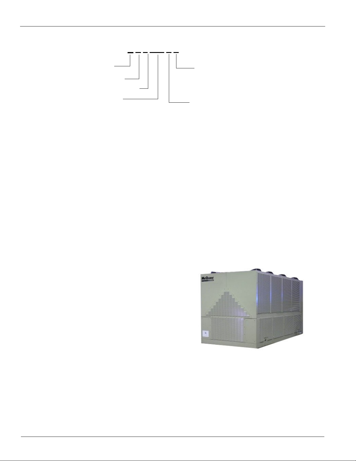
G Z XXX D H
Air-Cooled
Global Design
Scroll Compressor
Nominal Tons
Application
Design Vintage
H = Standard Packaged
Chiller Nomenclature
Features and Benefits
Unit Design Features
McQuay AGZ air-cooled Chillers are a product of the McQuay
commitment to offer quiet, reliable, energy efficient
equipment, incorporating high quality compressors, state-ofthe-art coil design, and innovative packaging.
Construction
AGZ chillers are factory-assembled and mounted on a heavygauge steel base. The base rails, supports and cabinetry are
powder-coat painted for long life. The base distributes the unit
weight for roof loading. Their small footprint allows smaller
mounting pads or support structures and is a plus for retrofit or
replacement applications.
Compressors
Reliable hermetic scroll compressors with cast iron scrolls and
three Teflon® impregnated bearings are used on the AGZ-D
chillers to promote longevity.
Each model has four to six steps of capacity modulation
depending on model size. One to six compressors can run,
depending on the load of the system, resulting in excellent
part-load efficiency and reduced annual operating costs.
Evaporator
Models AGZ-025 through AGZ-130
The evaporator is a compact, high efficiency, dual circuit,
brazed plate-to-plate type heat exchanger consisting of parallel
stainless steel plates. These heat exchangers provide excellent
heat exchange efficiency in a compact footprint and are
especially attractive for smaller capacity units.
Condenser Coils
Condenser coils have internally enhanced seamless copper
tubes arranged in a staggered row pattern. The coils are
mechanically expanded into McQuay lanced and rippled
aluminum fins with full fin collars. A variety of optional coil
material and coatings are available so that the unit can be
constructed to meet almost any environment. Options include
copper fins, black fin and ElectroFin® coating; see page 73 for
description of options.
Condenser Fans and Motors
Multiple direct-drive, dynamically balanced propeller fans
operate in formed venturi openings at low tip speeds for
maximum efficiency and minimum noise and vibration. A
heavy-gauge vinyl-coated fan guard protects each fan.
Each condenser fan motor (including the optional VFD fan
motor) is Totally Enclosed Air Over (TEAO), heavy-duty, 3phase with permanently lubricated ball bearings and inherent
overload protection. These motors are designed specifically for
outdoor use.
Figure 1: AGZ130D with Optional Full Louver Package
The water side working pressure is 653 psig (4502 kPa).
Evaporators are designed and constructed according to, and
listed by, Underwriters Laboratories (UL).
Models AGZ-140 through AGZ-190
The evaporator is direct-expansion, U-tube type with water
flowing in the baffled shell side and refrigerant flowing
through the tubes. Two independent refrigerant circuits within
the evaporator serve the unit's dual refrigerant circuits. The
water side working pressure is 152 psig (1048 kPa). Each
evaporator is designed, constructed, inspected, and stamped
according to the requirements of the ASME Boiler and
Pressure Vessel Code. Double thickness insulation is available
as an option.
4 CAT 611
Fan Deck
The fan deck is canted inward and directs discharge air toward
the center of the unit, reducing the tendency to spill over the
sides and into the coil, reducing capacity. This feature, combined with the coil design allows closer unit spacing than most
competitors. The result is a smaller installation footprint and
reduced first cost. The external condenser coils are fitted with
a standard wire mesh guards to protect the coil from damage.
Optional louvers create an attractive appearance that can
eliminate the need for screening walls
Page 5
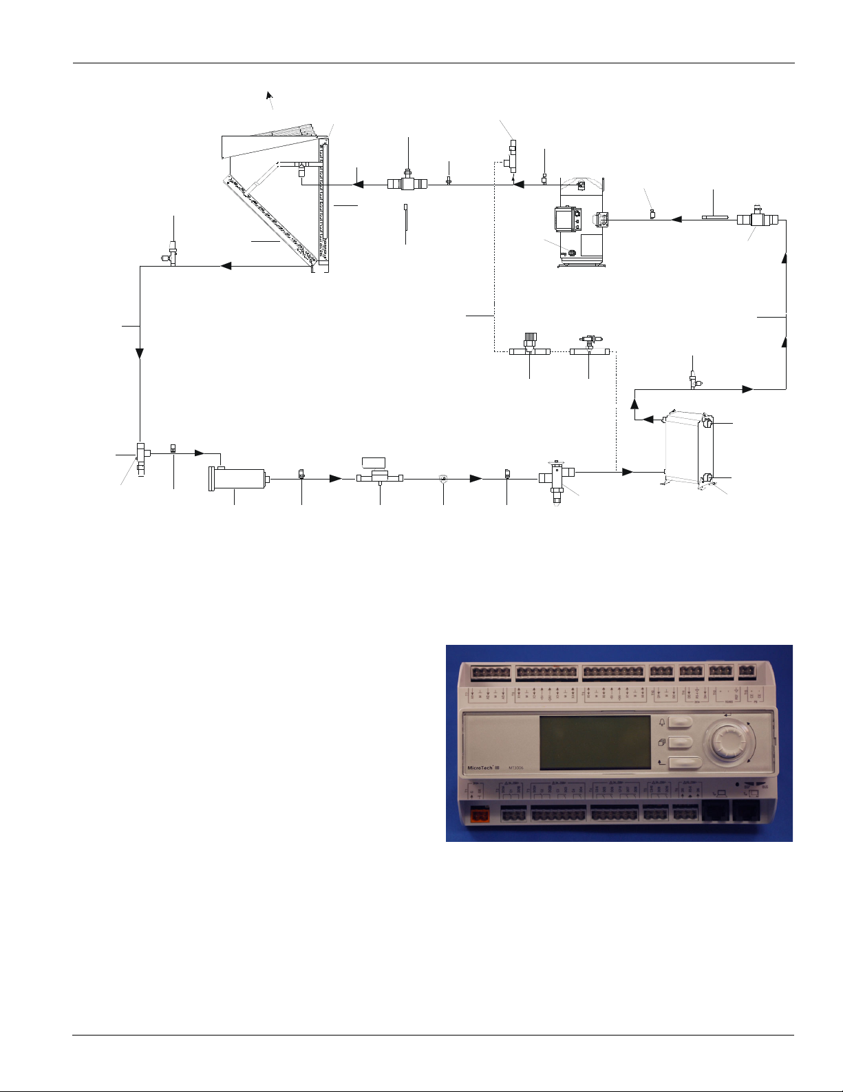
Figure 2: AGZ-D Piping Schematic (One circuit shown)
CHARGING
VA LVE
LIQUID
TUBI NG
LIQUI D
SHU T-OFF
SC H R A D ER
VALVE
FI LTER
R
SO LENOI D
VALVE
SIG H T
GLASS
THERMAL
EX PA N S I O N
VA LVE
WA TER
IN
WATER
OUT
PL A TE TYPE
EV AP O R A TOR
SUC TIO N
SHU T-OFF
BALL VALVE
(OPTIO NA L)
SUC TIO N
TUBIN G
SCHRAD ER
VALVE
DISCHA RGE
TUBIN G
AIR
FLO W
AI R
FLOW
AIR
FLOW
CONDENSER
A SSE M B LY
SC ROLL
C O M PR ESSO R
(TANDEM O R TRIO)
CHARGING
VA L VE
SC H RADER
VALVE
(HEADER)
(ST1, ST2)
SUC TION
TRANSDUCER
(WL1, WL2)
TRANSD UCER
(WH1, WH2)
OUTSIDE AIR
TEM PERATURE
(WAA)
SCHRA DER
VA LVE
SC H RAD ER
VALVE
BYPA SS
TUBING
(OPTIO NA L)
VALVE
TEMP. SENSOR
A C C ESS
FITTIN G
HGBP
VALVE
DISCHA RGE
SHU T-OFF
VA L VE
NOTES:
1. Evaporator is brazed-plate on AGZ 025-130 and shell-and-tube on AGZ 140-190.
2. Hot gas bypass (shown in dotted lines) is an option. The controls are factory installed.
3. Models 025 to 045 have TXV valves only, Models 140 to 190 have EXV valves only, Models 050 to 130 have TXV as
standard with EXV available as an option.
Features and Benefits
VALVE
DRIE
HOT G AS
SH UT-OFF
DI SCHA RGE
OIL
SIG H T
GLASS
SO LENOI D
HGBP
VALVE
SUC TIO N
TEMP. SENSOR
LEAVIN G WATER
(ON O PPOSITE SIDE)
Control System
The MicroTech III advanced DDC chiller controller surpasses
all other microprocessor-based chiller control systems
available today. This powerful, user-friendly control system
provides the flexibility and performance needed for either
stand-alone unit operation or the controller can be easily tied
into your building automation system of choice using
McQuay's Open Choices feature. Open Choices allows you to
choose from open standard protocols such as BACnet®,
Modbus and LonWorks® to communicate easily with the
building automation system that best meets your facility
requirements. These optional communications modules are
available factory installed or can be easily field installed.
The MicroTech III controller's state-of-the-art design will not
only permit the chiller to run more efficiently, but will also
simplify troubleshooting if a system failure occurs. Every
MicroTech III controller is programmed and tested prior to
shipment to help provide a trouble-free start-up.
Operator-friendly
The MicroTech III control menu structure is separated into
four distinct categories that provide the operator or service
technician with a full description of current unit status, control
parameters, and alarms. Security protection helps prevent
unauthorized changing of the setpoints and unit control
parameters.
CAT 611 5
Page 6

Features and Benefits
MicroTech III control continuously performs important selfdiagnostic checks while monitoring system temperatures,
pressures and protection devices. It will automatically
shutdown a compressor, a refrigerant circuit or the entire unit
if a fault occurs. The cause of the shutdown will be retained in
memory and can be easily displayed in plain English or metric
units for operator review. In addition to displaying alarm
diagnostics, the MicroTech III chiller controller also provides
the operator with a warning of pre-alarm conditions. Alarm
notification data can also be passed to a BAS through an
optional communication module.
Staging
The scroll compressors are staged on and off as a function of
leaving chilled water temperature. Lead/lag is automatic and
switched based on starts and operating hours.
Equipment Protection
The unit is protected in three ways:
1 alarms that shut the unit down and require manual reset
to restore unit operation,
2 alarms that shut the unit down and then restart
automatically (do notrequire manual restart), and
3 limit alarms that reduce unit capacity in response to
some out-of-limit condition. Shut down alarms activate
an alarm signal that can be exported to a remote location.
Limit alarms activate a light on the controller and do not
trigger a remote alarm.
Building Automation System (BAS) Interface
The following BAS protocols are supported:
•BACnet/IP
• BACnet MS/TP
• LonWorks (FTT-10A)
• Modbus
• All operating conditions, system alarms, control parameters and schedules are monitored.
Features
• Can be wired up to 1,000 feet (308 meters) from the unit
for flexibility in placing each remote user interface
within your building.
Benefits
• Allows you to access the user interface for each unit
from one location, inside the building.
• Users need to learn one format because the remote user
interface is identical to the unit-mounted version.
• No additional field commissioning is required for the
remote user interface.
• Can be retrofit after unit installation.
• Is fully compatible with the optional BAS communication modules.
Cable and Wiring Recommendations
Communications: Belden 9841 or equal AWG 22 twisted pair.
See McQuay manual IM1005 for wiring and installation
information.
Figure 3: Remote Interface Panel
Optional Remote Interface Panel
In addition to the unit-mounted user interface provided with
MicroTech III controls, the AGZ chillers can be individually
equipped with a remote user interface. It provides convenient
access to unit diagnostics and control adjustments, without
having to access a rooftop or outdoor location. One remote
panel can be connected to up to eight chillers.
Each remote user interface is similar to its unit-mounted
counterpart and offers the same functionality and display,
including:
• Three buttons and a navigating wheel with a 8 line by
30-character display format.
• Digital display of messages in English language.
6 CAT 611
Page 7
Application Considerations
Full Load Capacity Reduction (AGZ110-130)
0.0
1.0
2.0
0 8 12 16 20 24
Wall He ight (ft)
Distance = 4ft Distance = 5f t
Power Increase (AGZ110-130)
0.0
1.0
2.0
0 8 12 16 20 24
Wall Height (ft)
% Power Increase
Distance = 4ft Distance = 5ft
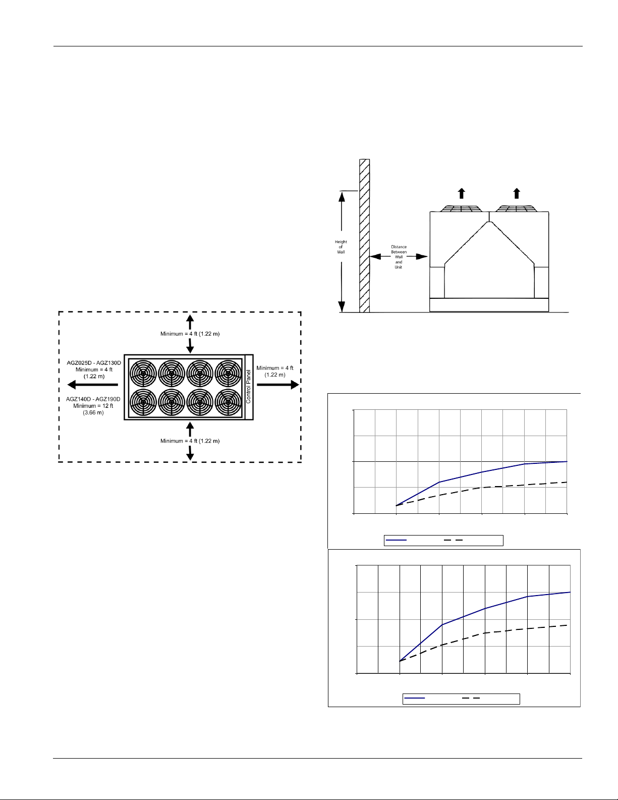
Unit Placement
AGZ units are for outdoor applications and can be mounted
either on a roof or at ground level. For roof mounted
applications, install the unit on a steel channel or I-beam frame
to support the unit above the roof. For ground level
applications, install the unit on a substantial base that will not
settle. Use a one-piece concrete slab with footings extended
below the frost line. Be sure the foundation is level within 0.5”
(13mm) over its length and width. The foundation must be
strong enough to support the weights listed in the Physical
Data Tables beginning on page 39.
Service Clearance
Sides: Minimum of 4 feet (1.22 m)
Control panel end: Minimum of 4 feet
Opposite control panel:
• Minimum 4 feet on models 025 to 130;
• 12 feet on models 140-190 (allows clearance to remove
the evaporator ).
Application Considerations
Case 1: Wall on One Side
In this case a solid wall up to 24-feet is considered. (For walls
higher than 24 ft., use the 24-foot values.) Also use these
charts for an adjacent building. For perforated screening walls,
use Case 4. Spacing is differentiated by unit size families.
Figure 4: Wall on One Side of Unit
Note: Maintain a minimum of 4-feet on all sides; except models
140-190, which require 12-feet opposite the control
panel to remove the evaporator.
For models AGZ 025-100: use 4 feet from any height wall. For
models 110-190, use Performance Adjustment curves below.
Figure 5: Case 1 Adjustment Factors (AGZ110D-130D)
Air Clearance
McQuay's advanced “W” coil design and open air-passage
ends allow very close unit spacing and a small installation
footprint. The AGZ-D fans are canted inward and reduce
recirculation by directing discharge air to the center of the unit,
reducing the tendency to flow outward and spill over into the
coil inlet.
Sufficient clearance must be maintained between the unit and
adjacent walls or other units to allow the required unit air flow
to reach the coils. Failure to do so will result in a capacity
reduction and an increase in power consumption. No
obstructions are allowed above the unit at any height.
Spacing Requirements
In general, with a small performance penalty in some cases,
AGZ-D units can be spaced at four feet from other units or a
wall. Curves on the following pages give the minimum
clearance for different types of installations and also capacity
reduction and power increase if closer spacing is used.
CAT 611 7
% Ca pacity Reduction
Page 8
Application Considerations
Full Loa d Ca pa city Re ducti on (AGZ140-180)
0.0
1.0
2.0
0 8 12 16 20 24
Wall Height (ft)
Distance = 4ft Distance = 6f t
Power Increase (AGZ140-180)
0.0
1.0
2.0
0 8 12 16 20 24
Wall Height (ft)
% Power Increase
Distance = 4ft Distance = 6ft
Full Load Capacity Reduction (AGZ190)
0.0
1.0
2.0
0 8 12 16 20 24
Wall Height (ft)
Dist ance = 4ft Distance = 5ft Distance = 7ft
Power Increase (AGZ190)
0.0
1.0
2.0
3.0
0 8 12 16 20 24
Wall Height (ft)
% Power Increase
Distance = 4ft Dis tan ce = 5 ft Distance = 7f t
Full Load Capacity Reduction
0.0
0.5
1.0
1.5
2.0
2.5
3.0
4568
Distance Be tw een Units (ft)
% Capacity Reducti on
AGZ075-100D AGZ110-130D AGZ140-180D AGZ190D
Power Increase
0.0
0.5
1.0
1.5
2.0
2.5
3.0
3.5
4.0
4.5
4568
Distance Between Units (ft)
% Power Increase
AGZ075-100D AGZ110-130D AGZ140-180D
D
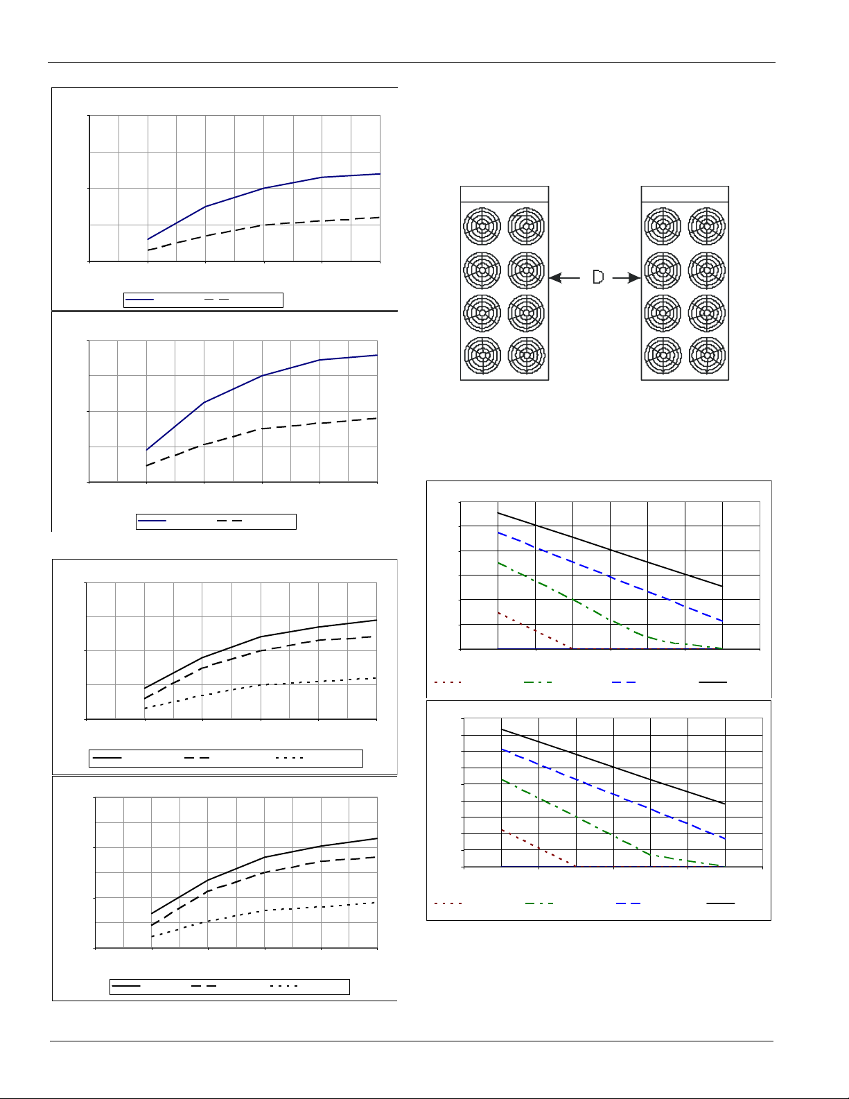
Figure 6: Case 1 Adjustment Factors (AGZ140D-180D)
% Capacity Reduction
Case 2: Two Units, Side-by-Side
Maintain a minimum of 6-feet on all sides; except models 140190, which require 12-feet opposite the control panel to
remove the evaporator.
Figure 8: Case 2 - Two units side by side
For models AGZ 025-100: use 4 feet between units. For
models 110-190, use Performance Adjustment chart in
Figure 9.
Figure 9: Case 2 Adjustment Factors
Figure 7: Case 1 Adjustment Factors (AGZ190D)
% Capacity Reduction
8 CAT 611
AGZ190
Page 9
Application Considerations
Full Load Capacity Reduction
0
1
2
3
4
5
6
4568
Distance Betwe en Units
% Capacity Reduction
AGZ075-100D AGZ110-130D AGZ 14 0-1 8 0D AGZ190D
Power Incre ase
0
1
2
3
4
5
6
7
8
9
4568
Distance Between Units (ft)
% Power Increase
AGZ075-100D AGZ110-130D AGZ140-180D AGZ190D
Wall Free Area vs. Distance
0
1
2
3
4
5
6
7
8
0 1020304050
% Open Wall Area
Distance from Wall to Unit (ft)
AGZ025-070 AGZ075-130 AGZ140-190
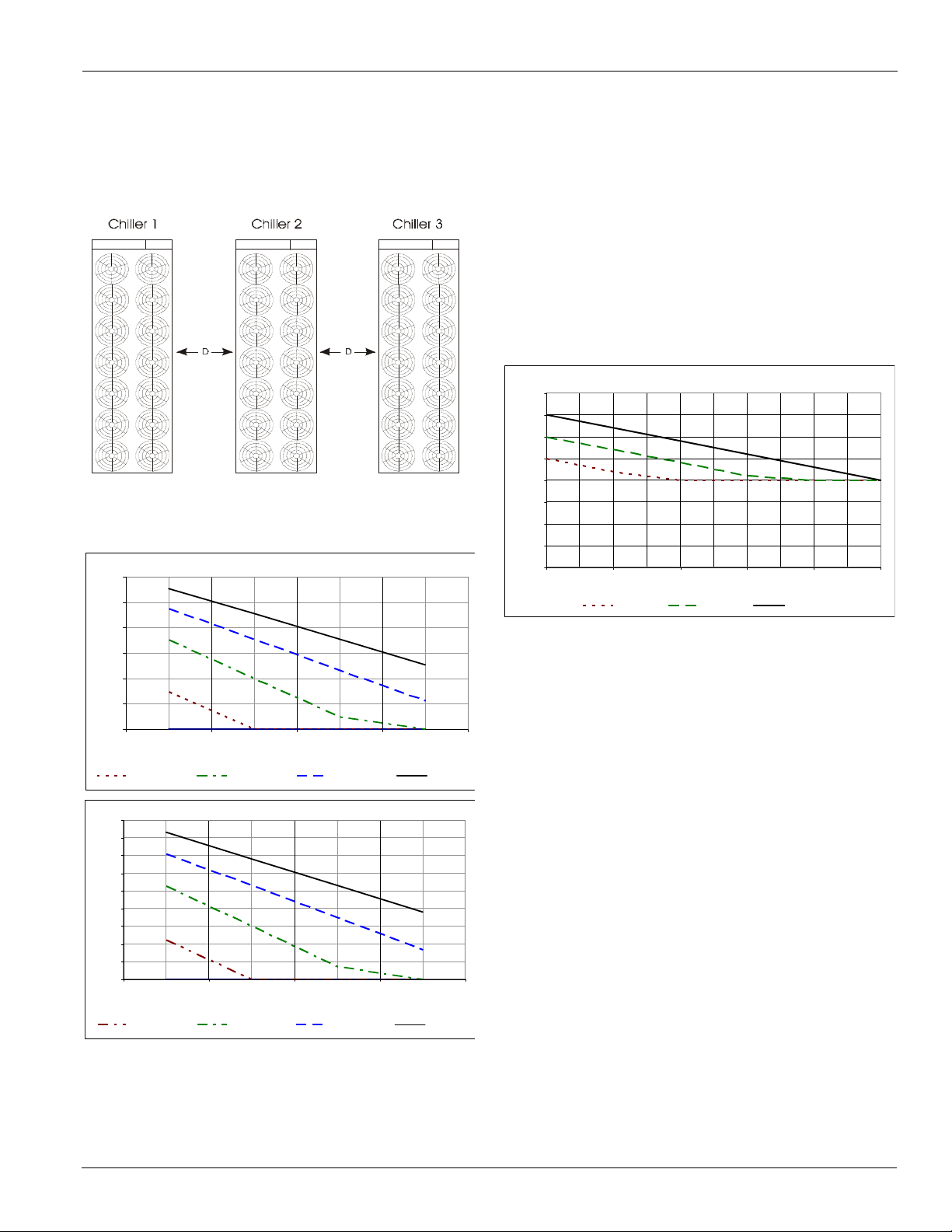
Case 3: Three or More Units, Side-by-Side
Maintain a minimum of 6-feet on all sides; except models 140190, which require 12-feet opposite the control panel to
remove the evaporator. For more than three units, allow an
additional 2-feet clearance between units.
Figure 10: Case 3 - 3 units side by side
Data is for the middle unit - with a unit on each side. See Case
2, page 8 for Adjustment Factors for the two outside units.
Figure 11: Case 3 Adjustment Factors
Case 4: Open Screening Walls
Decorative screening walls are often used to help conceal a
unit either on grade or on a rooftop. Design these walls such
that the combination of their open area and distance from the
unit do not require performance adjustment. It is assumed that
the wall height is equal to or less than the unit height when
mounted on its base support. If the wall height is greater than
the unit height, see Case 5, Pit Installation, page 10. The
distance from the sides of the unit to the side walls must be
sufficient for service, such as opening control panel doors. For
uneven wall spacing, the distance from the unit to each wall
can be averaged providing no distance is less than 4 feet.
Values are based on walls on all four-sides.
Figure 12: Case 4 Adjustment Factor
CAT 611 9
Page 10

Application Considerations
Full Load Capacity Reduction (AGZ025-07 0)
0.0
1.0
2.0
3.0
4.0
5.0
6.0
0 8 10 12 13 14
Depth of Pit (ft)
% Capacity Red uction
Distance = 4 ft Distance = 5 ft Distance = 6 ft
Power Increase (AGZ025-070)
0.0
1.0
2.0
3.0
4.0
5.0
6.0
7.0
8.0
9.0
0 8 10 12 13 14
Depth of Pit (ft)
% Power Increase
Distance = 4 ft Distance = 5 ft Distance = 6 ft
Full Load Capacity Reduction (AGZ075-130)
0
1
2
3
4
5
6
0 8 10 12 13 14
Depth of Pit (ft)
% Capacity Reduction
Distance = 5 ft Distance = 6 ft Distance = 8 ft
Power Increase (AGZ075-130)
0.0
1.0
2.0
3.0
4.0
5.0
6.0
7.0
8.0
9.0
0 8 10 12 13 14
Depth of Pit / Wall Height (ft)
% Power In crease
Distance = 5 ft Distance = 6 f t Dis tance = 8 ft
Full Load Capacity Reduction (AGZ140-190)
0.0
1.0
2.0
3.0
4.0
5.0
6.0
0 8 10 12 13 14
Depth of Pit (ft)
% Capacity Reduction
Distance = 6 ft Di sta nc e = 8 f t Dis tan ce = 10 f t
Power Increase (AGZ140-190)
0.0
1.0
2.0
3.0
4.0
5.0
6.0
7.0
8.0
9.0
0 8 10 12 13 14
Depth of Pit / Wall He ight (ft)
% Power Increase
Distance = 6 ft Distance = 8 ft Distance = 10 ft
Case 5: Pit Installation
Pit installations can cause operating problems resulting from
recirculation and restriction, and require care that sufficient air
clearance is provided, safety requirements are met and service
access is provided. Pit covers must have abundant open area at
least equal to the chiller footprint.A solid wall surrounding a
unit is substantially a pit and this data should be used.
Steel grating is sometimes used to cover a pit to prevent
accidental falls or trips into the pit. The grating material and
installation design must be strong enough to prevent such
accidents, yet provide abundant open area to avoid
recirculation problems. Have any pit installation reviewed by
the McQuay sales representative prior to installation to ensure
it has sufficient air-flow characteristics, and approved by the
installation design engineer avoid risk of accident.
Figure 13: Case 5 - Pit Installation
Figure 15: Case 5 Adjustment Factors (AGZ075D-130D)
Figure 14: Case 5 Adjustment Factors (AGZ025D-070D)
10 CAT 611
Figure 16: Case 5 Adjustment Factors (AGZ140D-190D)
Page 11
Application Considerations
Chilled Water Piping
Follow all instructions and recommendations for Chilled Water
Piping in IM 1100, available on www.mcquay.com. Design the
water piping so the chilled water circulating pump discharges
into the evaporator inlet. A 40-mesh strainer must be installed
in the inlet pipe to the chiller to avoid debris entering the
evaporator. The strainer may be field-supplied, or is available
as field-installed kit. See Optional Inlet Strainer below for
more information.
A water flow switch must be installed in the horizontal piping
of the supply (evaporator outlet) water line to avoid evaporator
freeze-up under low or no flow conditions. The flow switch
may be ordered as a factory-installed option, a field-installed
kit, or may be supplied and installed in the field (See Options
and Accessories, page 73for more information).
Vibration eliminators are recommended in both the supply and
return water lines. Pressure gauges must be installed in the
inlet and outlet water lines to the evaporator.
Insulate chilled water piping to reduce heat loss and prevent
condensation. Chillers not running in the winter should have
their water systems thoroughly drained to protect against
freezing. If the chiller operates year-round, or if the system is
not drained for the winter, protect the chilled water piping
exposed to outdoor temperature against freezing. Wrap the
lines with a heater cable and add proper amount of glycol to
the system to further protect the system.
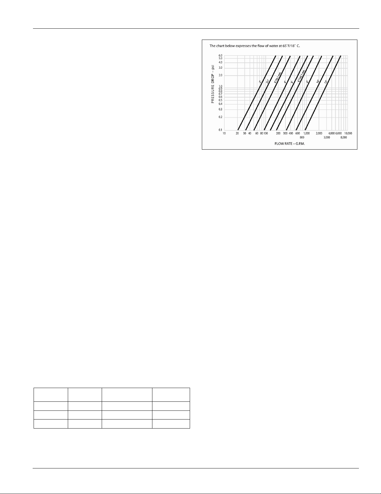
Optional Inlet Strainer
An inlet water strainer kit is available to be field-installed,
sized per Table 1 and with the pressure drop show in
Figure 17. This pressure drop must be accounted for in the
total system pressure drop. The kit consists of:
• (1) Y-type 40% open area strainer with 304 stainless
steel perforated basket, Victaulic pipe connections and
strainer cap
• (1) Extension pipe with (2) Schrader fittings that can be
used for a pressure gauge and thermal dispersion flow
switch. The pipe provides sufficient clearance from the
evaporator for strainer basket removal.
• (1) ½-inch blowdown valve
• (2) Victaulic clamps
Table 1: Strainer Data
AGZ Model
025-055 2.5 16.75 14
060-130 3.0 17.75 20
140-190 8.0 36.00 125
Strainer
Size (in.)
Strainer Plus Pipe
Length (in.)
Strainer
Weight (lbs)
Figure 17: Strainer Pressure Drop
Water Flow Limitations
Constant Flow
The evaporator flow rates and pressure drops shown on page
page 45 are for full load design purposes. The maximum flow
rate and pressure drop are based on a 6°F temperature drop.
Avoid higher flow rates with resulting lower temperature drops
to prevent potential control problems resulting from very small
control bands and limited start up/shut off temperature
changes.
The minimum flow and pressure drop is based on a full load
evaporator temperature drop of 16°F. Evaporator flow rates
below the minimum values can result in laminar flow causing
freeze-up problems, scaling and poor control. Flow rates above
the maximum values will result in unacceptable pressure drops
and can cause excessive erosion, potentially leading to failure.
Evaporator Variable Flow
Reducing evaporator flow in proportion to load can reduce
system power consumption. The rate of flow change should be
a maximum of 10 percent of the flow per minute. For example,
if the maximum design flow is 200 gpm and it will be reduced
to a flow of 140 gpm, the change in flow is 60 gpm. Ten
percent of 200 gpm equals 20 gpm change per minute, or a
minimum of three minutes to go from maximum to minimum.
Do not reduce flow lower than the minimum flows listed in the
evaporator pressure drop section, page 45. The water flow
through the vessel must remain between the minimum and
maximum values listed on page 45. If flow drops below the
minimum allowable, large reductions in heat transfer can
occur. If the flow exceeds the maximum rate, excessive
pressure drop and tube erosion can occur.
CAT 611 11
Page 12

Application Considerations
Figure 18: Typical Piping, Brazed-Plate Evaporator (models AGZ025D-130D)
Figure 19: Typical Piping, Shell and Tube Evaporator (models AGZ140D-190D)
Typical Piping
Piping for units with brazed-plate evaporators must have a
drain and vent connection provided in the bottom of the lower
connection pipe and to the top of the upper connection pipe
respectively. These evaporators do not have drain or vent
connections due to their construction.
System Water Volume Considerations
All chilled water systems need adequate time to recognize a
load change, respond to the change and stabilize to avoid
undesirable short cycling of the compressors or loss of
temperature control. In air conditioning systems, the potential
for short cycling usually exists when the building load falls
below the minimum chiller plant capacity or on close-coupled
systems with very small water volumes. Some of the things the
designer should consider when looking at water volume are the
minimum cooling load, the minimum chiller plant capacity
12 CAT 611
during the low load period and the desired cycle time for the
compressors. Assuming that there are no sudden load changes
and that the chiller plant has reasonable turndown, a rule of
thumb of “gallons of water volume equal to two to three times
the chilled water gpm flow rate” is often used. A storage tank
may have to be added to the system to reach the recommended
system volume.
Evaporator Freeze Protection
Evaporator freeze-up can be a concern in the application of aircooled water chillers. To protect against freeze-up, insulation
and electric heaters are furnished with the unit. Models 140
through 190 have immersion heaters with a thermostat; models
025 through 130 have an external plate heater and thermostat.
They protect the evaporator down to -20°F (-29°C) ambient air
temperature. Although the evaporator is equipped with freeze
protection, it does not protect water piping external to the unit
or the evaporator itself if there is a power failure or heater
Page 13

Application Considerations
cable burnout. Consider the following recommendations for
additional protection.
1 If the unit will not be operated during the winter, drain
evaporator and chilled water piping and flush with
glycol. Drain and vent connections are provided on the
evaporator to ease draining.
2 Add a glycol solution to the chilled water system to
provide freeze protection. Freeze point should be
approximately 10°F below minimum design ambient
temperature.
3 The addition of thermostatically controlled heat and
insulation to exposed piping.
The evaporator heater cable is factory wired to the 115 volt
circuit in the control box. This power should be supplied from
a separate source to maximize unit protection, but it can be
supplied from the control circuit. Operation of the heaters is
automatic through the ambient sensing thermostat that
energizes the evaporator heaters for protection against freezeup. Unless the evaporator is drained in the winter or contains
an adequate concentration of anti-freeze, the disconnect switch
to the evaporator heater must not be open.
Temperature and Water Flow Limitations
Low Ambient Operation
Compressor staging is adaptively determined by system load,
ambient air temperature, and other inputs to the MicroTech III
control. A low ambient option with fan VFD allows operation
down to -10° F (-23° C). The minimum ambient temperature is
based on still conditions where the wind is not greater than
five mph. Greater wind velocities will result in reduced
discharge pressure, increasing the minimum operating ambient
temperature. Field installed hail/wind guards are available to
allow the chiller to operate effectively down to the ambient
temperature for which it was designed.
High Ambient Operation
AGZ-D units for high ambient operation (105ºF to 125 F, 40.1
C to 51.7 C) require the addition of the optional high ambient
package that includes a small fan with a filter in the air intake
to cool the control panel.
All units with the optional VFD low ambient fan control
automatically include the high ambient option.
Evaporator flow rates below the minimum values can result in
laminar flow causing freeze-up problems, scaling and poor
control. Flow rates above the maximum values will result in
unacceptable pressure drops and can cause excessive erosion,
potentially leading to failure.
Operating and Standby Limits
Table 2: Operating Limits
Maximum standby ambient temperature 130°F (55°C)
Maximum operating ambient temperature 105°F (40°C)
-with optional high ambient package (see information under High Ambient Operation 125°F (52°C)
Minimum operating ambient temperature (standard control) 35°F (2°C)
Minimum operating ambient temperature (with optional low-ambient control) -10°F (-23°C)
Leaving chilled water temperature 40°F to 60°F (2°C to 16°C)
Leaving chilled fluid temperatures (with anti-freeze) - Unloading is not permitted with fluid leaving
temperatures below 25°F (-4°C). When ambient air temperature is above 100º F, minimum leaving
chilled fluid temperature (with antifreeze) is 25°F (4°C)
Operating chilled water delta-T range 6 to 16°F (-14 to -9°C)
Maximum evaporator operating inlet fluid temperature 76°F (24°C)
Maximum evaporator non-operating inlet fluid temperature 100°F (38°C)
15°F to 60°F (-9°C to 16°C)
CAT 611 13
Page 14

Selction Procedure
tons 24
T F
-----------------------
gpm=
kW
4.18
T C
-------------------------------------
ls=
Selction Procedure
AGZ-D chillers are ideal for a wide range of applications and
operating conditions.
Selection with Inch-Pound (I-P) units
The performance tables beginning on page 16 cover the range
of leaving evaporator water temperatures and outside ambient
temperatures included under AHRI Standard 550/590-2003.
The tables are based on a 10°F (5.5°C) temperature drop
through the evaporator.
Adjustment factors for applications having other than a 10°F
(5.5°C) drop can be found in Table 5, page 15. The minimum
leaving chilled water temperature setpoint without glycol is
40°F (4ºC). For brine selections, see Tab le 3 and Table 4 on
page 15 for glycol adjustment factors. Ratings are based on a
0.0001 ft
level operation. For other fouling factors, different Delta-Ts, or
altitude correction factors see Table 5, page 15. For
applications outside the catalog ratings, please contact your
local McQuay sales representative.
Selection example
Given:
2
x hr x ºF/Btu fouling factor in the evaporator at sea
• 50 tons minimum
• 95°F ambient temperature
• 120 gpm, 54ºF to 44°F chilled water
• 0.0001 evaporator fouling factor
1 From Table 6, page 16, an AGZ 055D at the given
conditions will produce 52 tons with a unit kW input of
61.9 and a unit EER of 10.0.
2 Use the following formula to calculate any unknown
elements (water only):
Selection example using ethylene glycol
Given:
• 44 tons minimum
• 95°F ambient air temperature
• 54°F - 44°F chilled water temperature
• 0.0001 evaporator fouling factor
• Protect from freezing down to 0°F
1 From Table 3, page 15, select an ethylene glycol
concentration of 40% to protect against freezing at 0°F.
2 At 40% ethylene glycol, the adjustment factors are:
• Capacity = 0.980
• kW = 0.992
• GPM = 1.132
• Pressure Drop = 1.557
3 Select the AGZ 050D from Table 6, page 16 and correct
with 40% ethylene glycol factors.
4 Correct capacity = 0.980 X 48.1 tons = 47.1 tons
5 Correct kW = 0.992 X 57.1 kW = 56.6 kW
6 Calculate chilled water flow:
Water flow @ corrected capacity=
440. tons x 24 / 10 F = 105.6 gpm
Glycol flow (at 40% solution) =
1.132 x 105.6 gpm = 119.5 gpm
Determine the evaporator pressure drop. Using Figure 27,
page 45, enter at 106 gpm (water) and follow up to the
AGZ050 line intersect. Read horizontally to obtain an
evaporator pressure drop of 11 feet. Correct the pressure drop
for 40% solution = 1.557 x 11.3 feet = 17.6 feet for ethylene
glycol using Table 3, page 15.
3 Determine the evaporator pressure drop. Using
Figure 27, page 45, enter at about 124 gpm and follow
up to the AGZ 055 line intersect. Read horizontally to
obtain an evaporator pressure drop of 13 feet of water.
14 CAT 611
Selection with SI units
Use the SI tables and the same procedures as with I-P units.
Use the following formula to calculate any missing elements
(water only):
Page 15

Performance Data
Ethylene Glycol Factors for Models AGZ 025D to 130D
° F ° C
10
26 -3.3 0.998 0.998 1.036 1.097
20
18 -7.8 0.993 0.997 1.06 1.226
30
7 -14 0.987 0.995 1.092 1.369
40
-7 -22 0.98 0.992 1.132 1.557
50
-28 -33 0.973 0.991 1.182 1.791
Ethylene Glycol Factors for Models AGZ 140D to 190D
° F ° C
10
26 -3.3 0.994 0.998 1.038 1.101
20
18 -7.8 0.982 0.995 1.063 1.224
30
7 -14 0.97 0.992 1.095 1.358
40
-7 -22 0.955 0.987 1.134 1.536
50
-28 -33 0.939 0.983 1.184 1.755
% E.G.
Point
Flow PDCapacity Pow e r
Flow PD% E.G.
Point
Capacity Pow e r
Propylene Glycol Factors for Models AGZ 025D to 130D
° F ° C
10
26 -3.3 0.995 0.997 1.016 1.1
20
19 -7.2 0.987 0.995 1.032 1.211
30
9 -13 0.978 0.992 1.057 1.38
40
-5 -21 0.964 0.987 1.092 1.703
50
-27 -33 0.952 0.983 1.14 2.251
Propylene Glycol Factors for Models AGZ 140D to 190D
° F ° C
10
26 -3.3 0.988 0.996 1.019 1.097
20
19 -7.2 0.972 0.992 1.035 1.201
30
9 -13 0.951 0.987 1.059 1.351
40
-5 -21 0.926 0.979 1.095 1.598
50
-27 -33 0.906 0.974 1.142 2.039
Flo w PD% P.G.
Point
Capacity Pow e r
Flo w PD% P.G.
Point
Capacity Pow e r
Capacity and Power Derates, Models AGZ 025 to 130
°F °C Cap. P ower C ap. Po wer Cap. P ower Cap. Power
6 3.3 0.978 0.993 0.975 0.991 0.963 0.987 0.940 0.980
8 4.4 0.989 0.996 0.986 0.994 0.973 0.990 0.950 0.983
10 5.6 1.000 1.000 0.996 0.999 0.984 0.994 0.961 0.987
12 6.7 1.009 1.003 1.005 1.001 0.993 0.997 0.969 0.990
14 7.7 1.018 1.004 1.014 1.003 1.002 0.999 0.978 0.991
16 8.9 1.025 1.007 1.021 1.006 1.009 1.001 0.985 0.994
6 3.3 0.977 1.001 0.973 1.000 0.961 0.996 0.938 0.989
8 4.4 0.987 1.006 0.984 1.004 0.971 1.000 0.948 0.993
10 5.6 0.998 1.009 0.995 1.007 0.982 1.003 0.959 0.996
12 6.7 1.007 1.011 1.004 1.010 0.991 1.006 0.967 0.998
14 7.7 1.014 1.014 1.011 1.013 0.998 1.009 0.974 1.001
16 8.9 1.022 1.016 1.018 1.014 1.005 1.010 0.981 1.003
6 3.3 0.973 1.011 0.970 1.010 0.957 1.006 0.935 0.998
8 4.4 0.984 1.014 0.980 1.013 0.968 1.009 0.945 1.001
10 5.6 0.995 1.019 0.991 1.017 0.979 1.013 0.955 1.005
12 6.7 1.004 1.021 1.000 1.020 0.987 1.016 0.964 1.008
14 7.7 1.011 1.024 1.007 1.023 0.994 1.018 0.971 1.011
16 8.9 1.018 1.027 1.014 1.026 1.002 1.021 0.978 1.014
6 3.3 0.969 1.021 0.966 1.020 0.954 1.016 0.931 1.008
8 4.4 0.980 1.026 0.977 1.024 0.964 1.020 0.942 1.013
10 5.6 0.989 1.029 0.986 1.027 0.973 1.023 0.950 1.015
12 6.7 0.998 1.033 0.995 1.031 0.982 1.027 0.959 1.020
14 7.7 1.007 1.036 1.004 1.034 0.991 1.030 0.967 1.022
16 8.9 1.014 1.037 1.011 1.036 0.998 1.031 0.974 1.024
Sea
Level
2000
feet
4000
feet
6000
feet
Altitude
Water
Delta T
Fouling Factor
0.0001 (0.0176) 0.00025 (0.044) 0.00075 (0.132) 0.00175 (0.308)
Capac ity and Power Derates, Models AGZ 140 to 190
°F °C C a p . P o we r C a p. P o w er C a p. P o w e r C a p. P o we r
6 3.3 0.990 0.997 0.976 0.994 0.937 0.983 0.868 0.964
8 4.4 0.994 0.998 0.981 0.995 0.942 0.984 0.872 0.965
10 5.6 1.000 1.000 0.987 0.996 0.947 0.986 0.877 0.967
12 6.7 1.005 1.001 0.991 0.997 0.951 0.986 0.881 0.968
14 7.7 1.009 1.002 0.995 0.998 0.955 0.987 0.884 0.968
16 8.9 1.013 1.004 1.000 1.000 0.960 0.989 0.889 0.970
6 3.3 0.987 1.005 0.974 1.002 0.934 0.991 0.865 0.972
8 4.4 0.992 1.006 0.979 1.003 0.940 0.992 0.870 0.973
10 5.6 0.997 1.008 0.984 1.004 0.944 0.994 0.875 0.975
12 6.7 1.002 1.009 0.989 1.005 0.949 0.994 0.879 0.975
14 7.7 1.007 1.011 0.993 1.007 0.953 0.996 0.883 0.977
16 8.9 1.011 1.012 0.998 1.008 0.958 0.997 0.887 0.978
6 3.3 0.985 1.014 0.972 1.010 0.933 0.999 0.864 0.980
8 4.4 0.991 1.015 0.977 1.012 0.938 1.001 0.869 0.981
10 5.6 0.995 1.016 0.982 1.013 0.943 1.002 0.873 0.982
12 6.7 1.000 1.018 0.987 1.014 0.947 1.003 0.877 0.984
14 6.8 1.005 1.019 0.991 1.015 0.951 1.004 0.881 0.985
16 8.9 1.009 1.021 0.995 1.017 0.955 1.006 0.884 0.987
6 3.3 0.982 1.023 0.969 1.020 0.930 1.009 0.861 0.989
8 4.4 0.988 1.025 0.975 1.022 0.935 1.010 0.866 0.991
10 5.6 0.992 1.026 0.979 1.022 0.940 1.011 0.870 0.992
12 6.7 0.997 1.028 0.984 1.024 0.944 1.013 0.875 0.994
14 7.7 1.002 1.029 0.989 1.025 0.949 1.014 0.879 0.995
16 8.9 1.006 1.031 0.992 1.027 0.952 1.016 0.882 0.996
2000
feet
4000
feet
6000
feet
Altitude
Sea
Level
Wate r
De lta T
Fouling Factor
0.0001 (0.0176) 0.00025 (0.044) 0.00075 (0.132) 0.00175 (0.308)
Note: Due to different performance characteristics, the factors
shown in the following tables are separated into brazedplate evaporators (AGZ025D - 130D) and shell-and-tube
evaporators (AGZ140D - 190D).
Ethylene & Propylene Glycol Factors
AGZ units can operate with a leaving chilled fluid temperature
range of 20°F (-6°C) to 60°F (10°C). A glycol solution is
required when leaving chilled fluid temperature is below 40°F
(4.6°C). The use of glycol will reduce the performance of the
unit depending on concentration.
Note: Ethylene and propylene glycol ratings are outside the
scope of AHRI Standard 550/590-2003 certification
program.
Table 3: Ethylene Glycol Correction Factors
Performance Data
Altitude Correction Factors
Performance tables are based at sea level. Elevations other
than sea level affect the performance of the unit. The decreased
air density will reduce condenser capacity consequently
reducing the unit's performance. For performance at elevations
other than sea level refer to Table 5.
Table 5: Capacity and Power Derates
Table 4: Propylene Glycol Correction Factors
CAT 611 15
Page 16

Performance Data
Unit Power Unit Unit Power Unit Unit Power Unit Unit Power Unit Unit Power Unit
T o n s k Wi EER T o n s k W i EER T o n s k Wi EER T o n s k W i EER T o n s k Wi EER
40
29 27.4 12.6 27 30.2 10.8 26 33.6 9.2 24 37.3 7.7 22 41.4 6.4
42
30 27.6 12.9 28 30.5 11.1 26 33.8 9.4 25 37.6 7.9 23 41.8 6.6
44
31 27.9 13.1 29 30.8 11.3
27 34.1 9.6
26 37.9 8.1 24 42.1 6.7
46
32 28.2 13.4 30 31.1 11.5 28 34.4 9.8 26 38.2 8.3 24 42.5 6.9
48
32 28.5 13.7 31 31.3 11.8 29 34.7 10.0 27 38.5 8.4 25 42.9 7.0
50
33 28.8 13.9 32 31.6 12.0 30 35.1 10.2 28 38.8 8.6 26 43.3 7.2
40
33 31.7 12.6 32 35.0 10.8 30 38.9 9.2 28 43.2 7.7 26 48.0 6.4
42
34 32.0 12.9 33 35.3 11.0 31 39.2 9.4 29 43.5 7.9 27 48.4 6.6
44
35 32.3 13.1 34 35.6 11.3
32 39.5 9.6
30 43.9 8.1 27 48.8 6.7
46
36 32.6 13.4 35 36.0 11.5 33 39.8 9.8 30 44.3 8.2 28 49.2 6.9
48
38 33.0 13.7 36 36.3 11.8 34 40.2 10.0 31 44.6 8.4 29 49.7 7.0
50
39 33.4 13.9 37 36.7 12.0 35 40.6 10.2 32 45.0 8.6 30 50.1 7.1
40
37 33.6 13.1 35 37.2 11.2 33 41.2 9.5 31 45.8 8.0 28 50.9 6.7
42
38 33.9 13.4 36 37.5 11.5 34 41.6 9.8 32 46.2 8.2 29 51.4 6.8
44
39 34.3 13.7 37 37.8 11.8
35 41.9 10.0
33 46.6 8.4 30 51.8 7.0
46
40 34.6 14.0 38 38.2 12.0 36 42.2 10.2 34 47.0 8.6 31 52.2 7.2
48
41 35.0 14.2 39 38.5 12.3 37 42.7 10.4 35 47.3 8.8 32 52.7 7.3
50
43 35.4 14.5 40 38.9 12.5 38 43.1 10.6 36 47.7 9.0 33 53.2 7.4
40
40 36.1 13.2 38 39.9 11.4 36 44.3 9.7 33 49.2 8.1 31 54.7 6.8
42
41 36.5 13.5 39 40.2 11.6 37 44.6 9.9 34 49.6 8.3 32 55.2 6.9
44
42 36.8 13.8 40 40.6 11.9
38 45.0 10.1
35 50.0 8.5 33 55.6 7.1
46
44 37.2 14.1 41 41.0 12.1 39 45.4 10.3 36 50.4 8.7 34 56.1 7.2
48
45 37.6 14.4 43 41.4 12.4 40 45.8 10.5 38 50.9 8.9 35 56.6 7.4
50
46 38.0 14.6 44 41.8 12.6 41 46.3 10.7 39 51.3 9.1 36 57.1 7.5
40
45 39.8 13.5 43 44.0 11.6 40 48.8 9.8 37 54.2 8.3 35 60.3 6.9
42
46 40.2 13.8 44 44.3 11.9 41 49.2 10.1 39 54.7 8.5 36 60.8 7.1
44
48 40.6 14.1 45 44.7 12.1
43 49.6 10.3
40 55.1 8.7 37 61.3 7.2
46
49 41.0 14.4 47 45.2 12.4 44 50.0 10.5 41 55.6 8.9 38 61.8 7.4
48
51 41.4 14.7 48 45.6 12.6 45 50.5 10.8 42 56.0 9.1 39 62.3 7.5
50
52 41.9 14.9 49 46.0 12.9 47 51.0 11.0 44 56.5 9.2 40 62.9 7.7
40
51 45.9 13.2 48 50.6 11.4 45 56.2 9.7 42 62.4 8.1 39 69.4 6.8
42
52 46.3 13.5 49 51.0 11.6 47 56.6 9.9 44 62.9 8.3 40 70.0 6.9
44
54 46.7 13.8 51 51.5 11.9
48 57.1 10.1
45 63.4 8.5 42 70.6 7.1
46
56 47.2 14.1 53 52.0 12.1 50 57.6 10.3 46 64.0 8.7 43 71.1 7.2
48
57 47.7 14.4 54 52.5 12.4 51 58.1 10.5 48 64.5 8.9 44 71.8 7.4
50
59 48.2 14.6 56 53.0 12.6 53 58.7 10.7 49 65.0 9.1 45 72.5 7.5
40
54 49.7 13.1 51 54.9 11.3 49 60.9 9.6 45 67.7 8.0 42 75.2 6.7
42
56 50.1 13.4 53 55.3 11.5 50 61.4 9.8 47 68.2 8.2 43 75.9 6.8
44
58 50.6 13.7 55 55.8 11.8
52 61.9 10.0
48 68.8 8.4 45 76.5 7.0
46
60 51.1 14.0 56 56.4 12.0 53 62.4 10.2 50 69.4 8.6 46 77.1 7.2
48
61 51.7 14.2 58 56.9 12.3 55 63.0 10.4 51 69.9 8.8 47 77.8 7.3
50
63 52.3 14.5 60 57.4 12.5 56 63.6 10.6 53 70.5 9.0 49 78.6 7.4
Unit
Siz e
Hz
Fan
Pow e r
(kW)
LWT
(°F)
Ambient Air Temperature
75
°
F
85
°
F
95
°
F
105
°
F
115
°
F
030D
050D 60 5.7
055D 60 5.7
025D 5.660
5.660
035D 5.660
5.6040D 60
5.7045D 60
Evaporator Temperature Drop Factors
Performance tables are based on a 10°F (5°C) temperature
drop through the evaporator. Adjustment factors for
applications with temperature ranges from 6°F to 16°F (3.3°C
to 8.9°C) are in Table 5. Temperature drops outside this 6°F to
16°F (3.3°C to 8.9°C) range can affect the control system's
capability to maintain acceptable control and are not
recommended.
Table 6: 60 Hz Full Load Performance Data (IP)
16 CAT 611
AHRI Certification
60Hz performance is certified per AHRI standard 550/590.
Ratings in bold are at AHRI standard conditions.
Page 17

Table 7: 60 Hz Full Load Performance Data (IP) (continued)
Unit Power Unit Unit Power Unit Unit Power Unit Unit Power Unit Unit Power Unit
T o n s k W i EER T o n s k Wi EER T o n s k W i EER T o n s k W i EER T o n s k Wi EER
40
59 55.2 12.8 56 60.9 11.0 53 67.6 9.4 49 75.1 7.9 46 83.5 6.6
42
61 55.6 13.1 58 61.4 11.3 54 68.1 9.6 51 75.7 8.1 47 84.2 6.7
44
63 56.2 13.4 60 62.0 11.5
56 68.7 9.8
52 76.3 8.2 49 84.9 6.9
46
65 56.7 13.7 61 62.6 11.8 58 69.2 10.0 54 77.0 8.4 50 85.6 7.0
48
67 57.4 13.9 63 63.1 12.0 60 69.9 10.2 56 77.6 8.6 51 86.3 7.2
50
69 58.0 14.2 65 63.7 12.3 61 70.6 10.4 57 78.2 8.8 53 87.2 7.3
40
61 54.4 13.5 58 60.0 11.6 55 66.6 9.8 51 74.0 8.3 47 82.2 6.9
42
63 54.8 13.8 60 60.5 11.9 56 67.1 10.1 53 74.6 8.5 49 83.0 7.0
44
65 55.4 14.1 62 61.1 12.1
58 67.7 10.3
54 75.2 8.7 50 83.7 7.2
46
67 55.9 14.4 64 61.7 12.4 60 68.2 10.5 56 75.9 8.8 52 84.3 7.4
48
69 56.5 14.7 65 62.2 12.6 62 68.9 10.7 58 76.5 9.1 53 85.1 7.5
50
71 57.2 14.9 67 62.8 12.9 64 69.6 11.0 59 77.1 9.2 55 85.9 7.7
40
67 63.7 12.7 64 70.3 10.9 60 78.0 9.3 56 86.7 7.8 52 96.3 6.5
42
70 64.2 13.0 66 70.9 11.2 62 78.7 9.5 58 87.4 8.0 54 97.2 6.6
44
72 64.9 13.3 68 71.5 11.4
64 79.3 9.7
60 88.1 8.2 55 98.0 6.8
46
74 65.5 13.6 70 72.2 11.6 66 79.9 9.9 62 88.9 8.3 57 98.8 6.9
48
76 66.2 13.8 72 72.9 11.9 68 80.7 10.1 64 89.6 8.5 59 99.7 7.1
50
78 67.0 14.0 74 73.6 12.1 70 81.5 10.3 66 90.3 8.7 61 100.6 7.2
40
77 72.2 12.8 73 78.7 11.1 69 86.3 9.6 64 94.8 8.1 59 104.3 6.8
42
79 72.8 13.1 75 79.5 11.4 71 86.9 9.8 66 95.5 8.3 61 105.1 7.0
44
82 73.5 13.3 78 80.2 11.6
73 87.7 10.0
68 96.3 8.5 63 105.9 7.2
46
84 74.1 13.6 80 80.9 11.9 75 88.5 10.2 70 97.1 8.7 65 106.8 7.3
48
87 74.7 14.0 82 81.6 12.1 78 89.2 10.4 73 97.8 8.9 67 107.7 7.5
50
90 75.4 14.2 85 82.1 12.4 80 90.0 10.7 75 98.8 9.1 69 108.6 7.6
40
85 81.7 12.5 81 89.1 10.9 76 97.7 9.4 71 107.3 8.0 66 118.1 6.7
42
88 82.4 12.8 83 90.0 11.1 79 98.4 9.6 73 108.1 8.2 68 119.0 6.9
44
91 83.2 13.1 86 90.8 11.4
81 99.3 9.8
76 109.0 8.3 70 119.9 7.0
46
94 83.9 13.4 89 91.6 11.6 84 100.2 10.0 78 109.9 8.5 72 121.0 7.2
48
96 84.6 13.7 91 92.4 11.9 86 101.0 10.2 81 110.7 8.7 74 121.9 7.3
50
99 85.4 14.0 94 93.0 12.2 89 101.9 10.4 83 111.8 8.9 77 122.9 7.5
40
94 89.9 12.5 89 98.0 10.9 84 107.5 9.4 78 118.0 8.0 73 129.8 6.7
42
97 90.6 12.8 92 98.9 11.1 87 108.2 9.6 81 118.9 8.2 75 130.8 6.9
44
100 91.5 13.1 95 99.8 11.4
89 109.2 9.8
83 119.9 8.3 77 131.8 7.0
46
103 92.3 13.4 98 100.7 11.6 92 110.2 10.0 86 120.9 8.5 79 133.0 7.2
48
106 93.0 13.7 101 101.6 11.9 95 111.1 10.2 89 121.8 8.7 82 134.1 7.3
50
109 93.9 14.0 104 102.2 12.2 98 112.0 10.5 91 123.0 8.9 84 135.2 7.5
40
105 102.7 12.2 100 111.9 10.7 94 122.8 9.2 88 134.9 7.8 81 148.4 6.6
42
108 103.6 12.5 103 113.1 10.9 97 123.7 9.4 90 135.9 8.0 84 149.5 6.7
44
112 104.6 12.8 106 114.1 11.1
100 124.8 9.6
93 137.0 8.2 86 150.6 6.9
46
115 105.5 13.1 109 115.1 11.4 103 125.9 9.8 96 138.2 8.3 89 152.0 7.0
48
119 106.3 13.4 112 116.1 11.6 106 126.9 10.0 99 139.2 8.5 92 153.3 7.2
50
122 107.3 13.7 116 116.8 11.9 109 128.0 10.2 102 140.5 8.7 94 154.5 7.3
070D
065D
Unit
Siz e
100D
090D
080D
075D
Hz
Fan
Pow e r
(kW)
LWT
(°F)
Ambient Air Temperature
75
°
F
85
°
F
95
°
F
105
°
F
115
°
F
10.9
10.9
10.9
10.9
060D 5.7
7.3
7.3
60
60
60
60
60
60
60
Performance Data
CAT 611 17
Page 18

Performance Data
Unit Power Unit Unit Power Unit Unit Power Unit Unit Power Unit Unit Power Unit
T o n s k Wi EER T o n s k Wi EER T o n s k W i EER T o n s k Wi EER T o n s k Wi EER
40
111 106.9 12.5 106 116.5 10.9 100 127.8 9.4 93 140.4 8.0 86 154.5 6.7
42
115 107.8 12.8 109 117.7 11.1 103 128.7 9.6 96 141.5 8.2 89 155.6 6.9
44
119 108.9 13.1 113 118.7 11.4
106 129.9 9.8
99 142.6 8.3 92 156.8 7.0
46
122 109.8 13.4 116 119.8 11.6 109 131.1 10.0 102 143.8 8.5 95 158.2 7.2
48
126 110.7 13.7 120 120.8 11.9 113 132.1 10.2 105 144.8 8.7 97 159.5 7.3
50
130 111.7 14.0 123 121.6 12.2 116 133.3 10.5 108 146.3 8.9 100 160.8 7.5
40
123 118.0 12.5 117 128.6 10.9 110 141.1 9.4 103 155.0 8.0 95 170.5 6.7
42
127 119.0 12.8 120 129.9 11.1 114 142.1 9.6 106 156.2 8.2 98 171.8 6.9
44
131 120.2 13.1 124 131.1 11.4
117 143.4 9.8
109 157.5 8.3 101 173.1 7.0
46
135 121.2 13.4 128 132.2 11.6 121 144.7 10.0 113 158.7 8.5 104 174.7 7.2
48
139 122.2 13.7 132 133.4 11.9 124 145.8 10.2 116 159.9 8.7 107 176.1 7.3
50
143 123.3 14.0 136 134.2 12.2 128 147.1 10.4 120 161.5 8.9 111 177.5 7.5
40
136 133.3 12.2 129 145.3 10.7 122 159.4 9.2 114 175.1 7.8 105 192.6 6.6
42
140 134.5 12.5 133 146.8 10.9 126 160.5 9.4 117 176.4 8.0 109 194.1 6.7
44
145 135.8 12.8 138 148.1 11.1
130 162.0 9.6
121 177.9 8.2 112 195.5 6.9
46
149 136.9 13.1 142 149.4 11.4 134 163.5 9.8 125 179.3 8.4 115 197.3 7.0
48
154 138.0 13.4 146 150.7 11.6 138 164.8 10.0 129 180.6 8.5 119 198.9 7.2
50
159 139.3 13.7 151 151.6 11.9 142 166.2 10.2 132 182.4 8.7 122 200.6 7.3
40
143 131.8 13.0 136 143.7 11.4 128 157.6 9.7 120 173.2 8.3 111 190.5 7.0
42
148 133.0 13.3 140 145.1 11.6 132 158.8 10.0 123 174.5 8.5 114 191.9 7.1
44
152 134.2 13.6 145 146.4 11.8
136 160.2 10.2
127 175.9 8.7 118 193.4 7.3
46
157 135.4 13.9 149 147.7 12.1 140 161.6 10.4 131 177.3 8.9 121 195.1 7.5
48
162 136.5 14.2 153 149.0 12.4 145 162.9 10.7 135 178.6 9.1 125 196.7 7.6
50
167 137.8 14.5 158 149.9 12.7 149 164.4 10.9 139 180.4 9.3 129 198.3 7.8
40
161 151.4 12.8 153 165.0 11.1 144 181.0 9.6 135 198.9 8.1 125 218.7 6.8
42
166 152.7 13.1 158 166.7 11.4 149 182.3 9.8 139 200.3 8.3 129 220.4 7.0
44
171 154.2 13.3 163 168.1 11.6
153 184.0 10.0
143 202.0 8.5 133 222.0 7.2
46
177 155.4 13.6 168 169.6 11.9 158 185.6 10.2 148 203.6 8.7 137 224.1 7.3
48
182 156.7 14.0 173 171.1 12.1 163 187.1 10.4 152 205.1 8.9 141 225.9 7.5
50
188 158.2 14.2 178 172.2 12.4 168 188.7 10.7 157 207.1 9.1 145 227.7 7.6
40
181 177.2 12.2 172 193.1 10.7 162 211.9 9.2 151 232.7 7.8 140 256.0 6.6
42
187 178.7 12.5 177 195.1 10.9 167 213.4 9.4 156 234.5 8.0 144 257.9 6.7
44
193 180.4 12.8 183 196.8 11.1
172 215.3 9.6
161 236.4 8.2 149 259.9 6.9
46
199 181.9 13.1 188 198.5 11.4 178 217.2 9.8 166 238.3 8.3 153 262.2 7.0
48
205 183.4 13.4 194 200.2 11.6 183 219.0 10.0 171 240.1 8.5 158 264.4 7.2
50
211 185.2 13.7 200 201.5 11.9 188 220.9 10.2 176 242.4 8.7 163 266.5 7.3
40
189 176.1 12.9 180 192.0 11.2 169 210.6 9.6 158 231.3 8.2 146 254.4 6.9
42
195 177.6 13.2 185 193.9 11.5 175 212.1 9.9 163 233.0 8.4 151 256.4 7.1
44
201 179.3 13.5 191 195.6 11.7
180 214.0 10.1
168 235.0 8.6 156 258.3 7.2
46
208 180.8 13.8 197 197.3 12.0 186 215.9 10.3 173 236.9 8.8 160 260.7 7.4
48
214 182.3 14.1 203 199.0 12.2 191 217.6 10.5 179 238.6 9.0 165 262.8 7.5
50
221 184.0 14.4 209 200.3 12.5 197 219.6 10.8 184 241.0 9.2 170 264.9 7.7
Ambient Air Temperature
75
°
F
110D
125D
130D
140D
160D
180D
60
60
85
°
F
95
°
F
105
°
F
115
°
F
18.2
14.5
14.5
14.5
LWT
(°F)
60
60
60
Unit
Siz e
Hz
Fan
Pow er
(kW)
190D 21.8
18.2
18.2
60
60
Table 8: 60 Hz Full Load Performance Data (IP) (continued)
18 CAT 611
Page 19

Table 9: 60 Hz Full Load Performance Data (SI)
Unit Power Unit Unit Power Unit Unit Powe r Unit Unit Power Unit Unit Power Unit
kW kWi COP kW kWi COP kW kWi COP kW kWi COP kW kWi COP
5
102 28.1 3.6 97 30.7 3.2 92 33.7 2.7 86 37.0 2.3 81 40.8 2.0
6
104 28.3 3.7 99 30.9 3.2 94 33.9 2.8 89 37.3 2.4 83 41.1 2.0
7
107 28.6 3.8 102 31.2 3.3 97 34.2 2.8 91 37.6 2.4 85 41.4 2.1
8
110 28.8 3.8 105 31.5 3.3 100 34.4 2.9 94 37.9 2.5 88 41.7 2.1
9
113 29.1 3.9 108 31.7 3.4 102 34.7 2.9 96 38.1 2.5 90 42.0 2.1
10
116 29.4 4.0 111 32.0 3.5 105 35.1 3.0 99 38.4 2.6 92 42.4 2.2
5
118 32.5 3.6 112 35.6 3.1 106 39.0 2.7 100 42.9 2.3 93 47.2 2.0
6
121 32.8 3.7 115 35.8 3.2 109 39.3 2.8 103 43.2 2.4 96 47.6 2.0
7
124 33.1 3.8 118 36.1 3.3 112 39.6 2.8 106 43.5 2.4 99 48.0 2.1
8
128 33.4 3.8 122 36.4 3.3 115 39.9 2.9 108 43.9 2.5 101 48.3 2.1
9
131 33.7 3.9 125 36.7 3.4 118 40.3 2.9 112 44.2 2.5 104 48.7 2.1
10
135 34.0 4.0 128 37.1 3.5 121 40.6 3.0 114 44.5 2.6 107 49.1 2.2
5
130 34.6 3.8 124 37.8 3.3 117 41.4 2.8 110 45.5 2.4 101 50.2 2.0
6
133 34.9 3.8 127 38.1 3.3 120 41.7 2.9 113 45.9 2.5 104 50.6 2.1
7
137 35.1 3.9 131 38.3 3.4 124 42.0 2.9 116 46.2 2.5 107 50.9 2.1
8
141 35.4 4.0 134 38.6 3.5 127 42.3 3.0 119 46.6 2.6 110 51.3 2.1
9
145 35.7 4.1 138 38.9 3.5 131 42.7 3.1 122 47.0 2.6 113 51.8 2.2
10
149 36.0 4.1 142 39.3 3.6 134 43.1 3.1 125 47.4 2.6 116 52.2 2.2
5
141 37.2 3.8 134 40.6 3.3 127 44.5 2.9 119 48.9 2.4 110 53.9 2.0
6
145 37.5 3.9 138 40.9 3.4 131 44.8 2.9 122 49.3 2.5 113 54.3 2.1
7
149 37.7 4.0 142 41.1 3.5 135 45.1 3.0 126 49.6 2.5 116 54.7 2.1
8
153 38.0 4.0 146 41.5 3.5 138 45.5 3.0 129 50.0 2.6 120 55.1 2.2
9
157 38.3 4.1 150 41.8 3.6 142 45.9 3.1 133 50.4 2.6 123 55.6 2.2
10
161 38.7 4.2 154 42.2 3.6 146 46.2 3.1 136 50.9 2.7 126 56.1 2.2
5
158 41.0 3.9 151 44.7 3.4 143 49.0 2.9 134 53.9 2.5 124 59.4 2.1
6
163 41.3 3.9 155 45.0 3.4 147 49.4 3.0 137 54.3 2.5 127 59.9 2.1
7
167 41.6 4.0 160 45.3 3.5 151 49.7 3.0 141 54.7 2.6 131 60.3 2.2
8
172 41.9 4.1 164 45.7 3.6 155 50.1 3.1 145 55.1 2.6 134 60.8 2.2
9
177 42.3 4.2 168 46.1 3.7 159 50.5 3.2 149 55.6 2.7 138 61.3 2.3
10
181 42.6 4.3 173 46.5 3.7 164 51.0 3.2 153 56.1 2.7 142 61.8 2.3
5
179 47.2 3.8 170 51.5 3.3 162 56.4 2.9 151 62.1 2.4 140 68.4 2.0
6
184 47.5 3.9 175 51.9 3.4 166 56.9 2.9 155 62.5 2.5 144 69.0 2.1
7
189 47.8 4.0 180 52.2 3.5 171 57.2 3.0 160 62.9 2.5 148 69.4 2.1
8
194 48.2 4.0 185 52.6 3.5 175 57.7 3.0 164 63.5 2.6 152 70.0 2.2
9
199 48.6 4.1 190 53.1 3.6 180 58.2 3.1 168 64.0 2.6 156 70.6 2.2
10
205 49.1 4.2 195 53.5 3.6 185 58.7 3.1 173 64.5 2.7 160 71.2 2.2
5
192 51.1 3.8 183 55.8 3.3 173 61.2 2.8 162 67.3 2.4 150 74.2 2.0
6
197 51.5 3.8 188 56.2 3.3 178 61.7 2.9 166 67.8 2.5 154 74.8 2.1
7
203 51.9 3.9 193 56.6 3.4 183 62.0 3.0 171 68.2 2.5 159 75.2 2.1
8
208 52.3 4.0 199 57.0 3.5 188 62.5 3.0 176 68.8 2.6 163 75.8 2.1
9
214 52.7 4.1 204 57.5 3.5 193 63.1 3.1 181 69.4 2.6 167 76.5 2.2
10
220 53.2 4.1 209 58.0 3.6 198 63.6 3.1 185 70.0 2.6 172 77.1 2.2
Unit
Size
Hz
Fan
Pow er
(kW)
LWT
(°C)
Ambient Air Te mperature
25°C 30°C 35°C 40°C 45°C
025D 60 5.6
030D 60 5.6
035D 60 5.6
040D 60 5.6
045D 60 5.7
050D 60 5.7
055D 60 5.7
Performance Data
CAT 611 19
Page 20

Performance Data
Unit Power Unit Unit Powe r Unit Unit Power Unit Unit Power Unit Unit Power Unit
kW kWi COP kW kWi COP kW kWi COP kW kWi COP kW kWi COP
5
209 56.6 3.7 199 61.8 3.2 188 67.9 2.8 178 74.5 2.4 166 82.1 2.0
6
215 57.0 3.8 204 62.3 3.3 194 68.4 2.8 183 75.1 2.4 170 82.8 2.1
7
221 57.5 3.8 210 62.8 3.3 199 68.9 2.9 188 75.7 2.5 175 83.4 2.1
8
227 58.0 3.9 216 63.4 3.4 205 69.4 2.9 193 76.3 2.5 180 84.0 2.1
9
233 58.6 4.0 222 63.9 3.5 210 70.0 3.0 198 76.8 2.6 185 84.7 2.2
10
239 59.2 4.0 228 64.4 3.5 216 70.6 3.1 203 77.3 2.6 189 85.4 2.2
5
216 55.7 3.9 206 60.9 3.4 195 66.9 2.9 184 73.5 2.5 172 81.0 2.1
6
222 56.2 4.0 212 61.4 3.4 201 67.4 3.0 189 74.0 2.6 176 81.6 2.2
7
228 56.7 4.0 218 61.9 3.5 206 67.9 3.0 194 74.6 2.6 181 82.2 2.2
8
235 57.2 4.1 224 62.4 3.6 212 68.4 3.1 199 75.2 2.7 186 82.8 2.2
9
241 57.7 4.2 230 62.9 3.6 218 69.0 3.2 205 75.7 2.7 191 83.4 2.3
10
247 58.3 4.2 236 63.5 3.7 223 69.6 3.2 210 76.2 2.8 196 84.1 2.3
5
238 65.3 3.7 227 71.4 3.2 215 78.3 2.7 203 86.1 2.4 189 94.8 2.0
6
245 65.8 3.7 234 71.9 3.2 221 78.9 2.8 209 86.7 2.4 195 95.6 2.0
7
252 66.4 3.8 240 72.5 3.3 228 79.5 2.9 214 87.3 2.5 200 96.3 2.1
8
259 67.0 3.9 247 73.1 3.4 234 80.1 2.9 220 88.0 2.5 206 97.0 2.1
9
266 67.6 3.9 253 73.7 3.4 240 80.8 3.0 226 88.7 2.6 211 97.8 2.2
10
273 68.3 4.0 260 74.4 3.5 246 81.5 3.0 232 89.3 2.6 217 98.6 2.2
5
272 73.8 3.7 259 79.8 3.2 246 86.6 2.8 231 94.2 2.5 216 102.8 2.1
6
279 74.4 3.8 266 80.5 3.3 252 87.2 2.9 238 94.9 2.5 222 103.5 2.1
7
287 75.0 3.8 274 81.1 3.4 259 88.0 3.0 244 95.6 2.6 228 104.2 2.2
8
295 75.6 3.9 281 81.8 3.4 267 88.6 3.0 251 96.3 2.6 234 105.1 2.2
9
303 76.2 4.0 289 82.4 3.5 274 89.3 3.1 258 96.9 2.7 240 105.8 2.3
10
312 76.8 4.1 297 82.9 3.6 281 90.0 3.1 264 97.8 2.7 247 106.6 2.3
5
301 83.6 3.6 287 90.4 3.2 272 98.1 2.8 256 106.7 2.4 239 116.4 2.1
6
310 84.3 3.7 295 91.1 3.2 280 98.8 2.8 264 107.4 2.5 246 117.2 2.1
7
319 84.9 3.8 304 91.9 3.3 288 99.6 2.9 271 108.2 2.5 253 118.0 2.1
8
328 85.6 3.8 312 92.6 3.4 296 100.4 2.9 278 109.0 2.6 260 118.9 2.2
9
337 86.2 3.9 321 93.3 3.4 304 101.1 3.0 286 109.7 2.6 267 119.8 2.2
10
346 86.9 4.0 330 93.8 3.5 312 101.9 3.1 293 110.7 2.7 274 120.7 2.3
5
331 91.9 3.6 316 99.4 3.2 300 107.8 2.8 282 117.3 2.4 263 128.0 2.1
6
341 92.6 3.7 325 100.2 3.2 308 108.6 2.8 290 118.1 2.5 271 128.8 2.1
7
350 93.4 3.8 334 101.0 3.3 317 109.5 2.9 298 119.0 2.5 278 129.8 2.1
8
360 94.1 3.8 343 101.8 3.4 325 110.4 2.9 306 119.8 2.6 286 130.8 2.2
9
370 94.8 3.9 353 102.6 3.4 334 111.2 3.0 315 120.6 2.6 293 131.7 2.2
10
380 95.6 4.0 363 103.2 3.5 343 112.0 3.1 323 121.7 2.7 301 132.7 2.3
5
371 105.0 3.5 354 113.6 3.1 335 123.2 2.7 315 134.1 2.4 295 146.2 2.0
6
381 105.9 3.6 364 114.5 3.2 345 124.1 2.8 324 135.0 2.4 303 147.2 2.1
7
392 106.7 3.7 374 115.4 3.2 354 125.1 2.8 334 136.0 2.5 311 148.3 2.1
8
403 107.6 3.7 384 116.4 3.3 364 126.1 2.9 343 137.0 2.5 320 149.5 2.1
9
414 108.4 3.8 395 117.2 3.4 374 127.0 2.9 352 137.9 2.6 328 150.6 2.2
10
426 109.2 3.9 406 117.9 3.4 384 128.0 3.0 361 139.1 2.6 337 151.7 2.2
Unit
Siz e
Hz
Fan
Pow er
(kW)
LWT
(°C)
Ambient Air Temperature
25°C 30°C 35°C 40°C 45°C
060D 60 5.7
065D 60 7.3
070D 60 7.3
075D 60 10.9
080D 60 10.9
090D 60 10.9
100D 60 10.9
Table 10: 60 Hz Full Load Performance Data (SI) continued
20 CAT 611
Page 21

Table 11: 60 Hz Full Load Performance Data (SI) continued
Unit Power Unit Unit Power Unit Unit Power Unit Unit Powe r Unit Unit Pow er Unit
kW kWi COP kW kWi COP kW kWi COP kW kWi COP kW kWi COP
5
394 109.3 3.6 376 118.2 3.2 356 128.3 2.8 335 139.5 2.4 313 152.2 2.1
6
405 110.2 3.7 387 119.2 3.2 366 129.2 2.8 345 140.5 2.5 322 153.3 2.1
7
417 111.1 3.8 397 120.2 3.3 377 130.3 2.9 355 141.6 2.5 331 154.4 2.1
8
428 112.0 3.8 408 121.1 3.4 387 131.3 2.9 364 142.6 2.6 340 155.6 2.2
9
440 112.8 3.9 419 122.0 3.4 397 132.2 3.0 374 143.5 2.6 349 156.7 2.2
10
452 113.7 4.0 431 122.8 3.5 408 133.3 3.1 384 144.8 2.7 358 157.9 2.3
5
435 120.7 3.6 415 130.5 3.2 393 141.6 2.8 370 154.0 2.4 346 168.0 2.1
6
447 121.7 3.7 427 131.6 3.2 404 142.6 2.8 381 155.1 2.5 355 169.2 2.1
7
460 122.7 3.8 439 132.6 3.3 416 143.8 2.9 391 156.3 2.5 365 170.4 2.1
8
473 123.6 3.8 451 133.7 3.4 427 144.9 2.9 402 157.4 2.6 375 171.8 2.2
9
486 124.5 3.9 463 134.7 3.4 439 146.0 3.0 413 158.4 2.6 385 173.0 2.2
10
499 125.5 4.0 476 135.5 3.5 451 147.1 3.1 424 159.9 2.6 395 174.3 2.3
5
481 136.3 3.5 459 147.4 3.1 435 160.0 2.7 410 174.0 2.4 383 189.8 2.0
6
495 137.4 3.6 472 148.7 3.2 448 161.1 2.8 421 175.2 2.4 393 191.1 2.1
7
509 138.6 3.7 485 149.9 3.2 460 162.4 2.8 433 176.5 2.5 404 192.5 2.1
8
523 139.6 3.7 499 151.0 3.3 473 163.7 2.9 445 177.8 2.5 415 194.0 2.1
9
538 140.7 3.8 512 152.2 3.4 486 164.9 2.9 457 179.0 2.6 426 195.4 2.2
10
553 141.8 3.9 527 153.1 3.4 499 166.2 3.0 469 180.6 2.6 438 196.9 2.2
5
506 134.8 3.8 483 145.8 3.3 457 158.2 2.9 430 172.1 2.5 402 187.7 2.1
6
520 135.9 3.8 496 147.0 3.4 470 159.3 3.0 443 173.3 2.6 413 189.0 2.2
7
535 137.0 3.9 510 148.2 3.4 483 160.6 3.0 455 174.6 2.6 425 190.4 2.2
8
550 138.1 4.0 524 149.4 3.5 497 161.9 3.1 468 175.8 2.7 436 191.9 2.3
9
565 139.1 4.1 538 150.5 3.6 510 163.1 3.1 481 177.0 2.7 448 193.3 2.3
10
581 140.2 4.1 554 151.4 3.7 524 164.4 3.2 493 178.6 2.8 460 194.7 2.4
5
570 154.8 3.7 543 167.4 3.2 515 181.7 2.8 484 197.6 2.5 452 215.6 2.1
6
586 156.1 3.8 558 168.8 3.3 529 183.0 2.9 498 199.0 2.5 465 217.0 2.1
7
602 157.4 3.8 574 170.2 3.4 544 184.5 3.0 512 200.5 2.6 478 218.6 2.2
8
619 158.5 3.9 590 171.5 3.4 559 185.9 3.0 526 201.9 2.6 491 220.3 2.2
9
636 159.7 4.0 606 172.8 3.5 574 187.3 3.1 541 203.2 2.7 504 221.9 2.3
10
654 161.0 4.1 623 173.8 3.6 590 188.7 3.1 555 205.1 2.7 518 223.6 2.3
5
640 181.2 3.5 610 195.9 3.1 578 212.6 2.7 544 231.3 2.4 508 252.3 2.0
6
658 182.7 3.6 627 197.6 3.2 595 214.1 2.8 560 232.9 2.4 523 254.0 2.1
7
676 184.2 3.7 645 199.2 3.2 611 215.9 2.8 576 234.6 2.5 537 255.9 2.1
8
695 185.6 3.7 663 200.7 3.3 628 217.6 2.9 591 236.3 2.5 552 257.9 2.1
9
715 187.0 3.8 681 202.2 3.4 645 219.2 2.9 608 237.9 2.6 566 259.7 2.2
10
734 188.4 3.9 700 203.5 3.4 663 220.9 3.0 623 240.0 2.6 582 261.7 2.2
5
669 180.1 3.7 638 194.8 3.3 605 211.3 2.9 569 229.9 2.5 532 250.8 2.1
6
688 181.6 3.8 656 196.4 3.3 622 212.8 2.9 586 231.5 2.5 547 252.5 2.2
7
708 183.0 3.9 674 198.0 3.4 639 214.6 3.0 602 233.2 2.6 562 254.3 2.2
8
727 184.4 3.9 693 199.5 3.5 657 216.3 3.0 618 234.9 2.6 577 256.3 2.3
9
748 185.8 4.0 712 201.0 3.5 675 217.8 3.1 636 236.4 2.7 592 258.2 2.3
10
768 187.3 4.1 732 202.2 3.6 693 219.6 3.2 652 238.6 2.7 608 260.1 2.3
Unit
Siz e
Hz
Fan
Pow er
(kW)
LWT
(°C)
Ambient Air Temperature
25°C 30°C 35°C 40°C 45°C
110D 60 14.5
125D 60 14.5
130D 60 14.5
140D 60 18.2
160D 60 18.2
180D 60 18.2
190D 60 21.8
Performance Data
CAT 611 21
Page 22

Performance Data
Unit Power Unit Unit Power Unit Unit Power Unit Unit Power Unit Unit Power Unit
Tons kWi EER Tons kWi EER Tons kWi EER Tons kWi EER Tons kWi EER
40
24 21.9 13.1 23 24.2 11.2 21 26.8 9.5 20 29.8 8.0 18 33.1 6.7
42
25 22.1 13.4 23 24.4 11.5 22 27.1 9.7 21 30.1 8.2 19 33.4 6.8
44
25 22.3 13.6 24 24.6 11.7
23 27.3 10.0
21 30.3 8.4 20 33.7 7.0
46
26 22.5 13.9 25 24.9 12.0 23 27.5 10.2 22 30.6 8.6 20 34.0 7.1
48
27 22.8 14.2 26 25.1 12.2 24 27.8 10.4 23 30.8 8.8 21 34.3 7.3
50
28 23.1 14.4 26 25.3 12.5 25 28.0 10.6 23 31.1 8.9 21 34.6 7.4
40
28 25.4 13.0 26 28.0 11.2 25 31.1 9.5 23 34.5 8.0 21 38.4 6.7
42
28 25.6 13.3 27 28.3 11.5 25 31.3 9.7 24 34.8 8.2 22 38.7 6.8
44
29 25.8 13.6 28 28.5 11.7
26 31.6 10.0
25 35.1 8.4 23 39.1 7.0
46
30 26.1 13.9 29 28.8 12.0 27 31.9 10.2 25 35.4 8.6 23 39.4 7.1
48
31 26.4 14.2 30 29.0 12.2 28 32.2 10.4 26 35.7 8.8 24 39.7 7.3
50
32 26.7 14.4 30 29.3 12.5 29 32.5 10.6 27 36.0 8.9 25 40.1 7.4
40
30 26.9 13.6 29 29.7 11.7 27 33.0 9.9 25 36.6 8.3 24 40.7 6.9
42
31 27.2 13.9 30 30.0 11.9 28 33.3 10.1 26 36.9 8.5 24 41.1 7.1
44
32 27.4 14.2 31 30.2 12.2
29 33.5 10.4
27 37.2 8.7 25 41.4 7.3
46
33 27.7 14.5 32 30.5 12.5 30 33.8 10.6 28 37.6 8.9 26 41.8 7.4
48
34 28.0 14.8 33 30.8 12.7 31 34.1 10.8 29 37.9 9.1 27 42.1 7.6
50
35 28.3 15.0 34 31.1 13.0 32 34.5 11.0 30 38.2 9.3 27 42.5 7.7
40
33 28.9 13.7 31 31.9 11.8 30 35.4 10.0 28 39.3 8.4 26 43.7 7.0
42
34 29.2 14.0 32 32.2 12.1 31 35.7 10.3 29 39.7 8.6 26 44.1 7.2
44
35 29.4 14.3 33 32.5 12.3
31 36.0 10.5
29 40.0 8.8 27 44.5 7.3
46
36 29.7 14.6 34 32.8 12.6 32 36.3 10.7 30 40.4 9.0 28 44.9 7.5
48
37 30.1 14.9 35 33.1 12.9 33 36.6 10.9 31 40.7 9.2 29 45.3 7.7
50
38 30.4 15.2 36 33.4 13.1 34 37.0 11.1 32 41.0 9.4 30 45.7 7.8
40
37 31.9 14.0 35 35.2 12.0 33 39.0 10.2 31 43.4 8.6 29 48.2 7.2
42
38 32.1 14.3 36 35.5 12.3 34 39.4 10.5 32 43.7 8.8 30 48.6 7.3
44
40 32.5 14.6 38 35.8 12.6
35 39.7 10.7
33 44.1 9.0 31 49.0 7.5
46
41 32.8 14.9 39 36.1 12.8 36 40.0 10.9 34 44.5 9.2 32 49.4 7.7
48
42 33.1 15.2 40 36.5 13.1 38 40.4 11.2 35 44.8 9.4 32 49.9 7.8
50
43 33.5 15.5 41 36.8 13.4 39 40.8 11.4 36 45.2 9.6 33 50.4 8.0
40
42 36.7 13.7 40 40.5 11.8 38 44.9 10.0 35 49.9 8.4 32 55.5 7.0
42
43 37.0 14.0 41 40.8 12.1 39 45.3 10.3 36 50.3 8.6 33 56.0 7.2
44
45 37.4 14.3 42 41.2 12.3
40 45.7 10.5
37 50.8 8.8 35 56.5 7.3
46
46 37.7 14.7 44 41.6 12.6 41 46.0 10.7 38 51.2 9.0 36 56.9 7.5
48
47 38.1 14.9 45 42.0 12.9 42 46.5 10.9 40 51.6 9.2 37 57.4 7.7
50
49 38.6 15.2 46 42.4 13.1 44 47.0 11.2 41 52.0 9.4 38 58.0 7.8
40
45 39.8 13.6 43 43.9 11.7 40 48.7 9.9 38 54.1 8.3 35 60.2 7.0
42
46 40.1 13.9 44 44.3 11.9 42 49.1 10.1 39 54.6 8.5 36 60.7 7.1
44
48 40.5 14.2 45 44.7 12.2
43 49.5 10.4
40 55.0 8.7 37 61.2 7.3
46
49 40.9 14.5 47 45.1 12.5 44 49.9 10.6 41 55.5 8.9 38 61.7 7.4
48
51 41.3 14.8 48 45.5 12.7 45 50.4 10.8 43 56.0 9.1 39 62.2 7.6
50
52 41.8 15.0 50 46.0 13.0 47 50.9 11.0 44 56.4 9.3 40 62.8 7.7
Unit Size Hz
Fan
Pow e r
(kW)
LWT
(°F)
Ambie nt Air Te mpe rature
95
°
F
105
°
F
115
°
F
025D 50 4.6
4.6
75
°
F
85
°
F
035D 50 4.6
030D 50
040D 50 4.6
045D 50 4.7
050D 50
055D 50 4.7
4.7
Table 12: 50 Hz Full Load Performance Data (IP)
22 CAT 611
Page 23
Table 13: 50 Hz Full Load Performance Data (IP) continued
Unit Power Unit Unit Power Unit Unit Power Unit Unit Power Unit Unit Power Unit
Tons kWi EER Tons kWi EER Tons kWi EER Tons kWi EER Tons kWi EER
40
49 44.1 13.3 46 48.7 11.4 44 54.1 9.7 41 60.1 8.2 38 66.8 6.8
42
51 44.5 13.6 48 49.1 11.7 45 54.5 9.9 42 60.6 8.4 39 67.4 7.0
44
52 45.0 13.9 49 49.6 12.0
47 55.0 10.2
44 61.1 8.6 40 67.9 7.1
46
54 45.4 14.2 51 50.1 12.2 48 55.4 10.4 45 61.6 8.7 42 68.5 7.3
48
55 45.9 14.5 52 50.5 12.5 49 55.9 10.6 46 62.1 8.9 43 69.1 7.4
50
57 46.4 14.7 54 51.0 12.7 51 56.5 10.8 48 62.6 9.1 44 69.7 7.6
40
51 43.5 14.0 48 48.0 12.0 45 53.3 10.2 42 59.2 8.6 39 65.8 7.2
42
52 43.9 14.3 50 48.4 12.3 47 53.7 10.4 44 59.7 8.8 40 66.4 7.3
44
54 44.3 14.6 51 48.8 12.6
48 54.2 10.7
45 60.2 9.0 42 66.9 7.5
46
56 44.7 14.9 53 49.3 12.8 50 54.6 10.9 46 60.7 9.2 43 67.5 7.7
48
57 45.2 15.2 54 49.8 13.1 51 55.1 11.1 48 61.2 9.4 44 68.1 7.8
50
59 45.8 15.5 56 50.3 13.4 53 55.7 11.4 49 61.7 9.6 46 68.7 8.0
40
56 50.9 13.2 53 56.3 11.3 50 62.4 9.6 47 69.3 8.1 43 77.1 6.7
42
58 51.4 13.5 55 56.7 11.6 52 62.9 9.8 48 69.9 8.3 45 77.8 6.9
44
60 51.9 13.8 57 57.2 11.8
53 63.4 10.1
50 70.5 8.5 46 78.4 7.0
46
61 52.4 14.1 58 57.8 12.1 55 63.9 10.3 51 71.1 8.6 47 79.0 7.2
48
63 53.0 14.3 60 58.3 12.3 57 64.6 10.5 53 71.7 8.8 49 79.7 7.3
50
65 53.6 14.6 62 58.9 12.6 58 65.2 10.7 54 72.3 9.0 50 80.5 7.5
40
64 57.8 13.2 61 62.9 11.5 57 69.1 9.9 53 75.9 8.4 49 83.4 7.1
42
66 58.2 13.6 62 63.6 11.8 59 69.5 10.2 55 76.4 8.6 51 84.1 7.3
44
68 58.8 13.8 64 64.1 12.0
61 70.2 10.4
57 77.1 8.8 52 84.7 7.4
46
70 59.3 14.2 66 64.7 12.3 63 70.8 10.6 58 77.7 9.0 54 85.5 7.6
48
72 59.8 14.5 68 65.3 12.6 64 71.4 10.8 60 78.2 9.2 56 86.2 7.7
50
74 60.4 14.8 71 65.7 12.9 66 72.0 11.1 62 79.0 9.4 57 86.9 7.9
40
71 65.4 13.0 67 71.3 11.3 63 78.2 9.7 59 85.9 8.3 55 94.5 7.0
42
73 65.9 13.3 69 72.0 11.5 65 78.7 10.0 61 86.5 8.5 56 95.2 7.1
44
75 66.6 13.6 71 72.6 11.8
67 79.4 10.2
63 87.2 8.7 58 95.9 7.3
46
78 67.1 13.9 74 73.2 12.1 69 80.2 10.4 65 87.9 8.8 60 96.8 7.4
48
80 67.7 14.2 76 73.9 12.3 71 80.8 10.6 67 88.6 9.1 62 97.6 7.6
50
82 68.3 14.5 78 74.4 12.6 74 81.5 10.8 69 89.5 9.2 64 98.4 7.8
40
78 71.9 13.0 74 78.4 11.3 70 86.0 9.7 65 94.4 8.3 60 103.9 7.0
42
80 72.5 13.3 76 79.1 11.6 72 86.6 10.0 67 95.1 8.5 62 104.7 7.1
44
83 73.2 13.6 79 79.8 11.8
74 87.4 10.2
69 95.9 8.7 64 105.4 7.3
46
85 73.8 13.9 81 80.5 12.1 76 88.1 10.4 71 96.7 8.8 66 106.4 7.4
48
88 74.4 14.2 83 81.2 12.3 79 88.8 10.6 74 97.4 9.1 68 107.3 7.6
50
91 75.1 14.5 86 81.8 12.6 81 89.6 10.8 76 98.4 9.2 70 108.2 7.8
40
87 82.2 12.7 83 89.6 11.1 78 98.2 9.5 73 107.9 8.1 67 118.7 6.8
42
90 82.9 13.0 85 90.5 11.3 80 98.9 9.7 75 108.7 8.3 69 119.6 7.0
44
93 83.7 13.3 88 91.3 11.6
83 99.8 10.0
77 109.6 8.5 72 120.5 7.1
46
96 84.4 13.6 91 92.1 11.8 85 100.7 10.2 80 110.5 8.7 74 121.6 7.3
48
98 85.1 13.9 93 92.9 12.1 88 101.5 10.4 82 111.3 8.9 76 122.6 7.4
50
101 85.9 14.2 96 93.5 12.4 91 102.4 10.6 85 112.4 9.0 78 123.6 7.6
Uni t Siz e Hz
Fan
Pow e r
(kW)
LWT
(°F)
Ambient Air Te m pe r ature
95
°
F
105
°
F
115
°
F
060D 50 4.7
6.1
75
°
F
85
°
F
070D 50 6.1
065D 50
075D 50 9.0
080D 50 9.0
090D 50
100D 50 9.0
9.0
Performance Data
CAT 611 23
Page 24

Performance Data
Unit Power Unit Unit Power Unit Unit Power Unit Unit Power Unit Unit Power Unit
Tons kWi EER Tons kWi EER Tons kWi EER Tons kWi EER Tons kWi EER
40
92 85.5 13.0 88 93.2 11.3 83 102.3 9.7 77 112.3 8.3 72 123.6 7.0
42
95 86.3 13.3 91 94.2 11.5 85 103.0 10.0 80 113.2 8.5 74 124.5 7.1
44
98 87.1 13.6 93 95.0 11.8
88 103.9 10.2
82 114.1 8.7 76 125.4 7.3
46
102 87.8 13.9 96 95.8 12.1 91 104.9 10.4 85 115.0 8.8 78 126.6 7.4
48
105 88.5 14.2 99 96.6 12.3 94 105.7 10.6 87 115.9 9.1 81 127.6 7.6
50
108 89.4 14.5 102 97.3 12.6 96 106.6 10.8 90 117.0 9.2 83 128.7 7.8
40
102 94.4 13.0 97 102.9 11.3 91 112.9 9.7 85 124.0 8.3 79 136.4 7.0
42
105 95.2 13.3 100 103.9 11.5 94 113.7 10.0 88 124.9 8.5 82 137.4 7.1
44
109 96.1 13.6 103 104.9 11.8
97 114.7 10.2
91 126.0 8.7 84 138.5 7.3
46
112 96.9 13.9 106 105.8 12.1 100 115.8 10.4 94 127.0 8.8 87 139.7 7.4
48
116 97.7 14.2 110 106.7 12.3 103 116.7 10.6 97 127.9 9.1 89 140.9 7.6
50
119 98.7 14.5 113 107.4 12.6 106 117.7 10.8 99 129.2 9.2 92 142.0 7.8
40
113 106.7 12.7 107 116.3 11.1 101 127.5 9.5 94 140.1 8.1 87 154.1 6.8
42
117 107.6 13.0 111 117.4 11.3 104 128.4 9.7 97 141.1 8.3 90 155.3 7.0
44
120 108.6 13.3 114 118.5 11.6
108 129.6 10.0
101 142.3 8.5 93 156.4 7.1
46
124 109.5 13.6 118 119.5 11.8 111 130.8 10.2 104 143.5 8.7 96 157.9 7.3
48
128 110.4 13.9 121 120.5 12.1 114 131.8 10.4 107 144.5 8.9 99 159.1 7.4
50
132 111.5 14.2 125 121.3 12.4 118 133.0 10.6 110 145.9 9.0 102 160.4 7.6
40
119 105.5 13.5 113 115.0 11.8 106 126.1 10.1 99 138.5 8.6 92 152.4 7.2
42
123 106.4 13.8 116 116.1 12.0 110 127.0 10.4 102 139.6 8.8 95 153.5 7.4
44
126 107.4 14.1 120 117.1 12.3
113 128.2 10.6
106 140.7 9.0 98 154.7 7.6
46
130 108.3 14.4 124 118.2 12.6 117 129.3 10.8 109 141.9 9.2 101 156.1 7.7
48
134 109.2 14.8 127 119.2 12.8 120 130.3 11.1 112 142.9 9.4 104 157.4 7.9
50
138 110.2 15.1 131 120.0 13.2 124 131.5 11.3 115 144.3 9.6 107 158.7 8.1
40
134 121.1 13.2 127 132.0 11.5 120 144.8 9.9 112 159.1 8.4 103 175.0 7.1
42
138 122.1 13.6 131 133.3 11.8 123 145.8 10.2 115 160.3 8.6 107 176.3 7.3
44
142 123.3 13.8 135 134.5 12.0
127 147.2 10.4
119 161.6 8.8 110 177.6 7.4
46
147 124.4 14.2 139 135.7 12.3 131 148.5 10.6 123 162.9 9.0 113 179.3 7.6
48
151 125.4 14.5 143 136.9 12.6 135 149.7 10.8 126 164.1 9.2 117 180.7 7.7
50
156 126.6 14.8 148 137.7 12.9 139 151.0 11.1 130 165.7 9.4 120 182.2 7.9
40
150 141.8 12.7 143 154.5 11.1 134 169.5 9.5 125 186.2 8.1 116 204.8 6.8
42
155 143.0 13.0 147 156.0 11.3 139 170.7 9.7 129 187.6 8.3 120 206.3 7.0
44
160 144.3 13.3 152 157.4 11.6
143 172.2 10.0
134 189.1 8.5 124 207.9 7.1
46
165 145.5 13.6 156 158.8 11.8 147 173.8 10.2 138 190.7 8.7 127 209.8 7.3
48
170 146.7 13.9 161 160.2 12.1 152 175.2 10.4 142 192.0 8.9 131 211.5 7.4
50
175 148.1 14.2 166 161.2 12.4 156 176.7 10.6 146 193.9 9.0 135 213.2 7.6
40
157 140.9 13.4 149 153.6 11.7 141 168.5 10.0 131 185.1 8.5 122 203.6 7.2
42
162 142.1 13.7 154 155.1 11.9 145 169.7 10.3 135 186.4 8.7 125 205.1 7.3
44
167 143.5 14.0 159 156.5 12.2
149 171.2 10.5
140 188.0 8.9 129 206.6 7.5
46
172 144.7 14.3 164 157.8 12.4 154 172.7 10.7 144 189.5 9.1 133 208.5 7.7
48
178 145.9 14.6 168 159.2 12.7 159 174.1 10.9 148 190.9 9.3 137 210.2 7.8
50
183 147.2 14.9 174 160.2 13.0 164 175.7 11.2 153 192.8 9.5 141 211.9 8.0
Unit Size Hz
Fan
Pow e r
(kW)
LWT
(°F)
Ambient Air Temperature
95
°
F
105
°
F
115
°
F
110D 50 12.0
12.0
75
°
F
85
°
F
130D 50 12.0
125D 50
140D 50 15.1
160D 50 15.1
180D 50
190D 50 18.1
15.1
Table 14: 50 Hz Full Load Performance Data (IP) continued
24 CAT 611
Page 25
Table 15: 50 Hz Full Load Performance Data (SI)
Unit Power Unit Unit Power Unit Unit Power Unit Unit Power Unit Unit Powe r Unit
kW kWi COP kW kWi COP kW kWi COP kW kWi COP kW kWi COP
5
84 22.5 3.8 80 24.6 3.3 76 27.0 2.8 72 29.6 2.4 67 32.6 2.1
6
87 22.6 3.8 83 24.7 3.3 78 27.1 2.9 74 29.8 2.5 69 32.9 2.1
7
89 22.8 3.9 85 24.9 3.4 80 27.3 2.9 76 30.0 2.5 71 33.1 2.1
8
92 23.0 4.0 87 25.2 3.5 83 27.6 3.0 78 30.3 2.6 73 33.4 2.2
9
94 23.3 4.0 90 25.4 3.5 85 27.8 3.1 80 30.5 2.6 75 33.6 2.2
10
96 23.5 4.1 92 25.6 3.6 87 28.0 3.1 82 30.7 2.7 77 33.9 2.3
5
98 26.0 3.7 93 28.4 3.3 88 31.2 2.8 83 34.3 2.4 77 37.8 2.0
6
100 26.2 3.8 96 28.7 3.3 91 31.4 2.9 85 34.5 2.5 80 38.1 2.1
7
103 26.5 3.9 98 28.9 3.4 93 31.7 2.9 88 34.8 2.5 82 38.4 2.1
8
106 26.7 4.0 101 29.1 3.5 96 31.9 3.0 90 35.1 2.6 84 38.7 2.2
9
109 26.9 4.0 104 29.4 3.5 98 32.2 3.1 93 35.3 2.6 86 39.0 2.2
10
112 27.2 4.1 106 29.6 3.6 101 32.5 3.1 95 35.6 2.7 89 39.3 2.3
5
108 27.6 3.9 103 30.2 3.4 97 33.1 2.9 92 36.4 2.5 86 40.1 2.1
6
111 27.8 4.0 106 30.4 3.5 100 33.4 3.0 94 36.6 2.6 88 40.4 2.2
7
114 28.1 4.1 109 30.7 3.5 103 33.6 3.1 97 36.9 2.6 90 40.7 2.2
8
117 28.3 4.1 111 30.9 3.6 106 33.9 3.1 99 37.2 2.7 93 41.0 2.3
9
120 28.6 4.2 114 31.2 3.7 109 34.2 3.2 102 37.5 2.7 95 41.3 2.3
10
123 28.9 4.3 117 31.4 3.7 111 34.5 3.2 105 37.7 2.8 98 41.7 2.3
5
117 29.6 3.9 111 32.4 3.4 106 35.6 3.0 100 39.1 2.5 93 43.1 2.2
6
120 29.9 4.0 115 32.7 3.5 109 35.8 3.0 102 39.4 2.6 95 43.4 2.2
7
124 30.1 4.1 118 32.9 3.6 112 36.1 3.1 105 39.7 2.7 98 43.7 2.2
8
127 30.4 4.2 121 33.2 3.6 115 36.4 3.2 108 40.0 2.7 101 44.0 2.3
9
130 30.7 4.2 124 33.5 3.7 118 36.7 3.2 111 40.3 2.8 104 44.4 2.3
10
134 31.0 4.3 128 33.8 3.8 121 37.0 3.3 114 40.5 2.8 106 44.7 2.4
5
132 32.7 4.0 125 35.7 3.5 119 39.2 3.0 112 43.1 2.6 104 47.5 2.2
6
135 32.9 4.1 129 36.0 3.6 122 39.5 3.1 115 43.4 2.7 107 47.8 2.2
7
139 33.2 4.2 132 36.3 3.7 126 39.8 3.2 118 43.7 2.7 110 48.2 2.3
8
143 33.5 4.3 136 36.6 3.7 129 40.1 3.2 121 44.1 2.8 113 48.5 2.3
9
147 33.8 4.3 140 36.9 3.8 132 40.4 3.3 125 44.4 2.8 116 48.9 2.4
10
151 34.2 4.4 143 37.2 3.9 136 40.8 3.3 128 44.7 2.9 119 49.3 2.4
5
148 37.6 3.9 141 41.1 3.4 134 45.1 3.0 126 49.6 2.5 118 54.6 2.2
6
153 37.9 4.0 145 41.4 3.5 138 45.5 3.0 130 49.9 2.6 121 55.0 2.2
7
157 38.2 4.1 150 41.8 3.6 142 45.8 3.1 133 50.3 2.7 125 55.5 2.2
8
161 38.6 4.2 154 42.1 3.6 146 46.1 3.2 137 50.7 2.7 128 55.9 2.3
9
166 39.0 4.3 158 42.5 3.7 150 46.5 3.2 141 51.1 2.8 131 56.3 2.3
10
170 39.4 4.3 162 42.8 3.8 153 47.0 3.3 145 51.4 2.8 135 56.8 2.4
5
159 40.8 3.9 152 44.6 3.4 144 48.9 2.9 136 53.7 2.5 126 59.2 2.1
6
164 41.1 4.0 156 44.9 3.5 148 49.3 3.0 139 54.1 2.6 130 59.7 2.2
7
168 41.5 4.1 160 45.3 3.5 152 49.6 3.1 143 54.5 2.6 134 60.1 2.2
8
173 41.8 4.1 165 45.7 3.6 156 50.0 3.1 147 55.0 2.7 137 60.6 2.3
9
178 42.2 4.2 169 46.0 3.7 160 50.5 3.2 151 55.4 2.7 141 61.0 2.3
10
182 42.7 4.3 174 46.4 3.7 165 50.9 3.2 155 55.8 2.8 145 61.6 2.4
30°C 35°C
Unit
Siz e
25°C
Hz
Fan
Pow er
(kW)
025D
030D
40°C 45°C
50 4.6
LWT
(°C)
Ambient Air Tem perature
50 4.6
035D 50 4.6
040D
50 4.7
045D
50 4.6
50 4.7
50 4.7055D
050D
Performance Data
CAT 611 25
Page 26

Performance Data
Unit Power Unit Unit Power Unit Unit Power Unit Unit Power Unit Unit Power Unit
kW kWi COP kW kWi COP kW kWi COP kW kWi COP kW kWi COP
5
173 45.2 3.8 165 49.5 3.3 156 54.3 2.9 147 59.6 2.5 138 65.7 2.1
6
178 45.6 3.9 170 49.8 3.4 161 54.7 2.9 151 60.1 2.5 141 66.2 2.1
7
183 46.0 4.0 174 50.3 3.5 165 55.1 3.0 156 60.5 2.6 145 66.7 2.2
8
188 46.4 4.1 179 50.7 3.5 170 55.5 3.1 160 61.0 2.6 149 67.2 2.2
9
193 46.9 4.1 184 51.1 3.6 174 56.0 3.1 164 61.4 2.7 153 67.7 2.3
10
198 47.3 4.2 189 51.5 3.7 179 56.5 3.2 169 61.9 2.7 157 68.3 2.3
5
179 44.6 4.0 171 48.8 3.5 162 53.5 3.0 153 58.8 2.6 142 64.8 2.2
6
184 44.9 4.1 176 49.1 3.6 167 53.9 3.1 157 59.2 2.7 146 65.3 2.2
7
190 45.3 4.2 181 49.5 3.6 171 54.3 3.2 161 59.6 2.7 150 65.7 2.3
8
195 45.7 4.3 186 49.9 3.7 176 54.7 3.2 166 60.1 2.8 155 66.2 2.3
9
200 46.2 4.3 191 50.4 3.8 181 55.2 3.3 170 60.6 2.8 159 66.8 2.4
10
205 46.7 4.4 196 50.8 3.9 185 55.7 3.3 175 61.0 2.9 163 67.3 2.4
5
198 52.2 3.8 189 57.1 3.3 179 62.7 2.9 168 68.8 2.4 157 75.9 2.1
6
203 52.7 3.9 194 57.5 3.4 184 63.1 2.9 173 69.4 2.5 162 76.5 2.1
7
209 53.1 3.9 199 58.0 3.4 189 63.6 3.0 178 69.9 2.5 166 77.0 2.2
8
215 53.6 4.0 205 58.5 3.5 194 64.1 3.0 183 70.4 2.6 171 77.6 2.2
9
221 54.1 4.1 210 59.0 3.6 199 64.6 3.1 188 70.9 2.6 175 78.2 2.2
10
226 54.7 4.1 216 59.5 3.6 205 65.2 3.1 193 71.4 2.7 180 78.9 2.3
5
225 59.1 3.8 215 63.9 3.4 204 69.3 2.9 192 75.4 2.5 179 82.2 2.2
6
232 59.5 3.9 221 64.4 3.4 210 69.8 3.0 197 75.9 2.6 184 82.8 2.2
7
238 60.0 4.0 227 64.9 3.5 215 70.4 3.1 203 76.5 2.7 189 83.4 2.3
8
245 60.5 4.1 234 65.4 3.6 221 70.9 3.1 208 77.0 2.7 194 84.1 2.3
9
252 60.9 4.1 240 65.9 3.6 227 71.4 3.2 214 77.5 2.8 200 84.7 2.4
10
259 61.4 4.2 247 66.3 3.7 233 72.0 3.2 219 78.2 2.8 205 85.3 2.4
5
250 66.9 3.7 239 72.3 3.3 226 78.5 2.9 213 85.3 2.5 199 93.1 2.1
6
257 67.4 3.8 245 72.9 3.4 232 79.0 2.9 219 85.9 2.5 204 93.7 2.2
7
264 68.0 3.9 252 73.5 3.4 239 79.7 3.0 225 86.6 2.6 210 94.4 2.2
8
272 68.5 4.0 259 74.1 3.5 246 80.3 3.1 231 87.2 2.7 216 95.2 2.3
9
279 69.0 4.1 266 74.6 3.6 252 80.9 3.1 238 87.8 2.7 221 95.8 2.3
10
287 69.5 4.1 274 75.1 3.6 259 81.5 3.2 244 88.6 2.7 227 96.6 2.4
5
275 73.5 3.7 262 79.5 3.3 249 86.3 2.9 234 93.8 2.5 219 102.4 2.1
6
283 74.1 3.8 270 80.2 3.4 256 86.9 2.9 241 94.5 2.5 225 103.1 2.2
7
291 74.7 3.9 277 80.8 3.4 263 87.6 3.0 247 95.2 2.6 231 103.8 2.2
8
299 75.3 4.0 285 81.4 3.5 270 88.3 3.1 254 95.9 2.7 237 104.6 2.3
9
307 75.9 4.1 293 82.1 3.6 277 88.9 3.1 261 96.5 2.7 243 105.4 2.3
10
316 76.5 4.1 301 82.6 3.6 285 89.6 3.2 268 97.4 2.8 250 106.2 2.4
5
308 84.0 3.7 294 90.9 3.2 278 98.6 2.8 262 107.2 2.4 244 117.0 2.1
6
317 84.7 3.7 302 91.6 3.3 286 99.3 2.9 269 108.0 2.5 251 117.8 2.1
7
325 85.4 3.8 310 92.4 3.4 294 100.1 2.9 277 108.8 2.5 258 118.6 2.2
8
335 86.0 3.9 319 93.1 3.4 302 100.9 3.0 284 109.6 2.6 265 119.6 2.2
9
344 86.7 4.0 327 93.8 3.5 310 101.6 3.1 292 110.3 2.7 272 120.4 2.3
10
353 87.4 4.0 337 94.3 3.6 319 102.4 3.1 300 111.3 2.7 280 121.4 2.3
30°C 35°C
Unit
Size
Hz
Fan
Pow er
(kW)
25°C
060D
065D
40°C 45°C
50 4.7
LWT
(°C)
Ambient Air Temperature
50 6.1
070D 50 6.1
075D
50 9.0
080D
50 9.0
50 9.0
50 9.0100D
090D
Table 16: 50 Hz Full Load Performance Data (SI) continued
26 CAT 611
Page 27

Table 17: 50 Hz Full Load Performance Data (SI) continued
Unit Power Unit Unit Power Unit Unit Power Unit Unit Power Unit Unit Power Unit
kW kWi COP kW kWi COP kW kWi COP kW kWi COP kW kWi COP
5
327 87.4 3.7 312 94.6 3.3 296 102.6 2.9 278 111.6 2.5 260 121.8 2.1
6
336 88.2 3.8 321 95.4 3.4 304 103.4 2.9 286 112.4 2.5 267 122.6 2.2
7
346 88.9 3.9 330 96.1 3.4 313 104.2 3.0 294 113.2 2.6 275 123.5 2.2
8
356 89.6 4.0 339 96.9 3.5 321 105.0 3.1 302 114.0 2.7 282 124.5 2.3
9
366 90.2 4.1 348 97.6 3.6 330 105.8 3.1 311 114.8 2.7 290 125.4 2.3
10
376 91.0 4.1 358 98.2 3.6 339 106.6 3.2 319 115.9 2.7 297 126.3 2.4
5
361 96.5 3.7 344 104.4 3.3 326 113.3 2.9 307 123.2 2.5 287 134.4 2.1
6
371 97.3 3.8 354 105.3 3.4 336 114.1 2.9 316 124.1 2.5 295 135.3 2.2
7
382 98.1 3.9 364 106.1 3.4 345 115.0 3.0 325 125.0 2.6 303 136.3 2.2
8
393 98.9 4.0 374 107.0 3.5 355 115.9 3.1 334 125.9 2.7 311 137.4 2.3
9
403 99.6 4.0 384 107.8 3.6 364 116.8 3.1 343 126.7 2.7 320 138.4 2.3
10
415 100.4 4.1 395 108.4 3.6 374 117.7 3.2 352 127.9 2.7 328 139.5 2.4
5
400 109.1 3.7 381 117.9 3.2 361 128.0 2.8 340 139.2 2.4 317 151.9 2.1
6
411 110.0 3.7 392 118.9 3.3 372 128.9 2.9 350 140.2 2.5 327 152.9 2.1
7
423 110.9 3.8 403 119.9 3.4 382 129.9 2.9 360 141.2 2.5 336 154.0 2.2
8
434 111.7 3.9 414 120.8 3.4 392 131.0 3.0 369 142.2 2.6 345 155.2 2.2
9
446 112.5 4.0 425 121.7 3.5 403 131.9 3.1 380 143.2 2.7 354 156.4 2.3
10
459 113.4 4.0 437 122.5 3.6 414 133.0 3.1 389 144.5 2.7 363 157.5 2.3
5
420 107.8 3.9 401 116.6 3.4 380 126.6 3.0 357 137.7 2.6 334 150.2 2.2
6
432 108.7 4.0 412 117.6 3.5 390 127.5 3.1 368 138.6 2.7 343 151.2 2.3
7
444 109.6 4.1 423 118.6 3.6 401 128.5 3.1 378 139.7 2.7 353 152.3 2.3
8
457 110.5 4.1 435 119.5 3.6 412 129.5 3.2 388 140.7 2.8 362 153.5 2.4
9
469 111.3 4.2 447 120.4 3.7 424 130.5 3.2 399 141.6 2.8 372 154.6 2.4
10
482 112.2 4.3 460 121.1 3.8 435 131.5 3.3 409 142.9 2.9 382 155.8 2.5
5
473 123.8 3.8 451 133.9 3.4 427 145.3 2.9 402 158.1 2.5 376 172.5 2.2
6
486 124.9 3.9 464 135.1 3.4 439 146.4 3.0 414 159.2 2.6 386 173.6 2.2
7
500 125.9 4.0 476 136.1 3.5 452 147.6 3.1 425 160.4 2.7 397 174.9 2.3
8
514 126.8 4.1 490 137.2 3.6 464 148.7 3.1 437 161.5 2.7 408 176.3 2.3
9
528 127.8 4.1 503 138.2 3.6 477 149.8 3.2 449 162.6 2.8 418 177.5 2.4
10
543 128.8 4.2 517 139.1 3.7 490 151.0 3.2 460 164.1 2.8 430 178.9 2.4
5
531 144.9 3.7 507 156.8 3.2 480 170.1 2.8 452 185.0 2.4 422 201.8 2.1
6
546 146.1 3.7 521 158.1 3.3 494 171.3 2.9 465 186.3 2.5 434 203.2 2.1
7
561 147.3 3.8 535 159.3 3.4 507 172.7 2.9 478 187.7 2.5 446 204.7 2.2
8
577 148.4 3.9 550 160.6 3.4 521 174.1 3.0 491 189.0 2.6 458 206.3 2.2
9
593 149.6 4.0 565 161.8 3.5 535 175.3 3.1 504 190.3 2.7 470 207.8 2.3
10
610 150.7 4.0 581 162.8 3.6 550 176.7 3.1 517 192.0 2.7 483 209.4 2.3
5
555 144.1 3.9 530 155.8 3.4 502 169.1 3.0 472 183.9 2.6 441 200.6 2.2
6
571 145.2 3.9 545 157.1 3.5 516 170.3 3.0 486 185.2 2.6 454 202.0 2.2
7
587 146.4 4.0 560 158.4 3.5 531 171.7 3.1 500 186.6 2.7 466 203.5 2.3
8
604 147.5 4.1 575 159.6 3.6 545 173.0 3.2 513 187.9 2.7 479 205.0 2.3
9
620 148.7 4.2 591 160.8 3.7 560 174.3 3.2 528 189.1 2.8 492 206.5 2.4
10
638 149.8 4.3 608 161.8 3.8 575 175.7 3.3 541 190.9 2.8 505 208.1 2.4
30°C 35°C
Unit
Siz e
Hz
Fan
Pow er
(kW)
25°C
110D
125D
40°C 45°C
50 12.0
LWT
(°C)
Ambient Air Tem perature
50 12.0
130D 50 12.0
140D
50 15.1
160D
50 15.1
50 15.1
50 18.1190D
180D
Performance Data
CAT 611 27
Page 28

Part Load Performance Data (60 Hz)
Model % Load Tons kW EER IPLV Model % Load Tons kW EER IPLV
100 27 34.1 9.6 100 81 99.3 9.8
75 20 18.8 13.1 75 61 54.1 13.5
50 14 10.4 15.7 50 41 29.3 16.6
25 7 5.0 16.3 25 20 13.6 17.9
100 32 39.5 9.6 100 89 109.2 9.8
75 24 21.7 13.1 75 67 59.5 13.5
50 16 12.0 15.8 50 45 32.2 16.6
25 8 5.8 16.4 25 22 14.9 17.9
100 35 41.9 10.0 100 100 124.8 9.6
75 26 23.1 13.6 75 75 68.6 13.1
50 17 12.8 16.3 50 50 36.5 16.4
25 9 6.1 17.2 25 25 17.2 17.4
100 38 45.0 10.1 100 106 129.9 9.8
75 28 24.7 13.8 75 80 71.3 13.4
50 19 13.7 16.6 50 53 38.1 16.7
25 9 6.4 17.8 25 27 18.1 17.6
100 43 49.6 10.3 100 117 143.4 9.8
75 32 27.6 13.9 75 88 77.5 13.6
50 21 15.3 16.7 50 59 42.3 16.6
25 11 7.1 17.9 25 29 19.7 17.8
100 48 57.1 10.1 100 130 162.0 9.6
75 36 31.1 13.9 75 97 86.4 13.5
50 24 17.4 16.6 50 65 47.7 16.3
25 12 8.2 17.6 25 32 22.6 17.2
100 52 61.9 10.0 100 136 160.2 10.2
75 39 33.7 13.8 75 102 89.5 13.7
50 26 18.8 16.5 50 68 49.2 16.6
25 13 8.8 17.5 25 34 23.5 17.4
100 56 68.7 9.8 100 153 184.0 10.0
75 42 36.3 13.9 75 115 100.7 13.7
50 28 20.3 16.6 50 77 54.8 16.8
25 14 9.5 17.7 25 38 25.8 17.8
100 58 67.7 10.3 100 172 215.3 9.6
75 44 37.4 14.0 75 129 116.5 13.3
50 29 21.1 16.5 50 86 62.6 16.5
25 15 9.8 17.7 25 43 29.4 17.6
100 64 79.3 9.7 100 180 214.0 10.1
75 48 42.1 13.7 75 135 118.3 13.7
50 32 23.3 16.5 50 90 65.5 16.5
25 16 11.0 17.5 25 45 30.7 17.6
100 73 87.7 10.0
75 55 48.4 13.6
50 37 26.4 16.6
25 18 12.2 18.0
25 14.6
30 14.7
35 15.2
40 15.5
45 15.6
50 15.5
55 15.4
60 15.5
75 15.4
65 15.5
70 15.4
90 15.4
100 15.1
110 15.4
125 15.4
180 15.2
130 15.2
140 15.4
190 15.4
15.480
160 15.6
Part Load Performance Data (60 Hz)
Table 18: 60 Hz Part Load Performance Data (IP)
28 CAT 611
Page 29

Table 19: 60 Hz Part Load Performance Data (SI)
100 96. 0 33. 5 2. 9 100 285.2 99.3 2. 9
75 72.0 18. 5 3. 9 75 213. 9 54. 1 4. 0
50 48.0 10. 5 4. 6 50 142. 6 29. 3 4. 9
25 24.0 5. 0 4. 8 25 71. 3 13.6 5. 2
100 111.1 38. 5 2. 9 100 313. 6 109. 2 2. 9
75 83.3 21. 2 3. 9 75 235. 2 59. 5 4. 0
50 55.6 11. 8 4. 7 50 156. 8 32. 2 4. 9
25 27.8 5. 7 4. 9 25 78. 4 14.9 5. 2
100 122.7 41. 9 2. 9 100 350. 9 124. 8 2. 8
75 92.0 23. 1 4. 0 75 263. 2 68. 6 3. 8
50 61.4 12. 8 4. 8 50 175. 5 36. 5 4. 8
25 30.7 6. 1 5. 0 25 87. 7 17.2 5. 1
100 133.3 45. 0 3. 0 100 373. 1 129. 9 2. 9
75 99.9 24. 7 4. 0 75 279. 8 71. 3 3. 9
50 66.6 13. 7 4. 9 50 186. 5 38. 1 4. 9
25 33.3 6. 4 5. 2 25 93. 3 18.1 5. 2
100 149.8 49. 6 3. 0 100 411. 7 143. 4 2. 9
75 112. 3 27. 6 4. 1 75 308. 8 77. 5 4. 0
50 74.9 15. 3 4. 9 50 205. 9 42. 3 4. 9
25 37.4 7. 1 5. 2 25 102.9 19.7 5. 2
100 169.1 57. 1 3. 0 100 455. 7 162. 0 2. 8
75 126. 8 31. 1 4. 1 75 341. 8 86. 4 4. 0
50 84.6 17. 4 4. 9 50 227. 8 47. 7 4. 8
25 42.3 8. 2 5. 2 25 113.9 22.6 5. 0
100 181.4 61. 9 2. 9 100 478. 9 160. 2 3. 0
75 136. 1 33. 7 4. 0 75 359. 2 89. 5 4. 0
50 90.7 18. 8 4. 8 50 239. 5 49. 2 4. 9
25 45.4 8. 8 5. 1 25 119.7 23.5 5. 1
100 197.3 68. 7 2. 9 100 539. 0 184. 0 2. 9
75 147. 9 36. 3 4. 1 75 404. 3 100. 7 4. 0
50 98.6 20. 3 4. 9 50 269. 5 54. 8 4. 9
25 49.3 9. 5 5. 2 25 134.8 25.8 5. 2
100 204.3 67. 7 3. 0 100 605. 5 215. 3 2. 8
75 153. 2 37. 4 4. 1 75 454. 1 116. 5 3. 9
50 102. 1 21. 1 4. 8 50 302. 7 62. 6 4. 8
25 51.1 9. 8 5. 2 25 151.4 29.4 5. 2
100 225.4 79. 3 2. 8 100 633. 3 214. 0 3. 0
75 169. 0 42. 1 4. 0 75 474. 9 118. 3 4. 0
50 112. 7 23. 3 4. 8 50 316. 6 65. 5 4. 8
25 56.3 11. 0 5. 1 25 158. 3 30. 7 5. 2
100 257.0 87. 7 2. 9
75 192. 8 48. 4 4. 0
50 128. 5 26. 4 4. 9
25 64.3 12. 2 5. 3
COP I P LV
90
4. 5
4. 5
75
4. 5
70
4. 5
190
4. 5
65
4. 6
180
4. 5
60
4. 6
160
4. 6
55
4. 5
140
4. 5
50
4. 5
130
4. 4
45
4. 6
125
4. 5
40
4. 5
110
4. 5
35
4. 5
100
4. 4
25
4. 3
80
30
4. 3
Mode l % Load
Ca pa c i t y kWPower
kW
COP I PL V M od el % Load
Ca pa ci t y kWPower
kW
Part Load Performance Data (60 Hz)
CAT 611 29
Page 30

Part Load Performance Data (50 Hz)
Model % Load Tons kW EER IPLV Model % Load Tons kW EER IPLV
100 23 27.3 10.0 100 67 79.4 10.2
75 17 15.0 13.6 75 50 43.3 14.0
50 11 8.3 16.3 50 34 23.5 17.2
25 6 4.0 16.9 25 17 10.9 18.6
100 26 31.6 10.0 100 74 87.4 10.2
75 20 17.4 13.6 75 56 47.6 14.0
50 13 9.6 16.4 50 37 25.8 17.2
25 7 4.6 17.0 25 19 12.0 18.6
100 29 33.5 10.4 100 83 99.8 10.0
75 22 18.5 14.1 75 62 54.9 13.6
50 14 10.3 16.9 50 41 29.2 17.0
25 7 4.9 17.8 25 21 13.8 18.1
100 31 36.0 10.5 100 88 103.9 10.2
75 24 19.8 14.3 75 66 57.0 13.9
50 16 11.0 17.2 50 44 30.5 17.3
25 8 5.1 18.5 25 22 14.5 18.3
100 35 39.7 10.7 100 97 114.7 10.2
75 27 22.1 14.4 75 73 62.0 14.1
50 18 12.2 17.3 50 49 33.9 17.2
25 9 5.7 18.6 25 24 15.8 18.5
100 40 45.7 10.5 100 108 129.6 10.0
75 30 24.9 14.4 75 81 69.1 14.0
50 20 13.9 17.2 50 54 38.2 16.9
25 10 6.6 18.3 25 27 18.1 17.8
100 43 49.5 10.4 100 113 128.2 10.6
75 32 26.9 14.3 75 85 71.6 14.2
50 21 15.0 17.1 50 57 39.4 17.2
25 11 7.1 18.2 25 28 18.8 18.1
100 47 55.0 10.2 100 127 147.2 10.4
75 35 29.1 14.4 75 95 80.6 14.2
50 23 16.2 17.2 50 64 43.8 17.4
25 12 7.6 18.4 25 32 20.7 18.5
100 48 54.2 10.7 100 143 172.2 10.0
75 36 29.9 14.5 75 107 93.2 13.8
50 24 16.9 17.1 50 71 50.1 17.1
25 12 7.9 18.4 25 36 23.5 18.3
100 53 63.4 10.1 100 149 171.2 10.5
75 40 33.7 14.2 75 112 94.7 14.2
50 27 18.6 17.1 50 75 52.4 17.1
25 13 8.8 18.2 25 37 24.6 18.3
100 61 70.2 10.4
75 46 38.7 14.1
50 30 21.1 17.2
25 15 9.7 18.7
25 15.2
30 15.2
35 15.8
40 16.1
60 16.1
45 16.2
50 16.1
75 16.0
80 16.0
65 16.1
70 16.0
55 16.0
90 16.0
100 15.6
110 15.9
125 16.0
130 15.7
140 16.0
160 16.1
180 15.8
190 16.0
Part Load Performance Data (50 Hz)
Table 20: 50 Hz Part Load Performance Data (IP)
30 CAT 611
Page 31

Table 21: 50 Hz Part Load Performance Data (SI)
100 81.4 26.8 3. 0 100 236.7 79. 4 3. 0
75 61.1 14. 8 4. 1 75 177. 5 43.3 4. 1
50 40. 7 8.4 4. 9 50 118.3 23. 5 5. 0
25 20. 4 4.0 5. 1 25 59.2 10.9 5. 4
100 93.7 30.8 3. 0 100 260.3 87. 4 3. 0
75 70.3 17. 0 4. 1 75 195. 2 47.6 4. 1
50 46. 8 9.5 5. 0 50 130.2 25. 8 5. 0
25 23. 4 4.5 5. 2 25 65.1 12.0 5. 4
100 101. 9 33.5 3.0 100 291.3 99. 8 2. 9
75 76.4 18. 5 4. 1 75 218. 4 54.9 4. 0
50 50.9 10. 3 5. 0 50 145. 6 29.2 5. 0
25 25. 5 4.9 5. 2 25 72.8 13.8 5. 3
100 110. 6 36.0 3.1 100 309.6 103.9 3. 0
75 83.0 19. 8 4. 2 75 232. 2 57.0 4. 1
50 55.3 11. 0 5. 0 50 154. 8 30.5 5. 1
25 27. 7 5.1 5. 4 25 77.4 14.5 5. 4
100 124. 3 39.7 3.1 100 341.7 114.7 3. 0
75 93.2 22. 1 4. 2 75 256. 3 62.0 4. 1
50 62.2 12. 2 5. 1 50 170. 9 33.9 5. 0
25 31. 1 5.7 5. 4 25 85.4 15.8 5. 4
100 140. 4 45.7 3.1 100 378.2 129.6 2. 9
75 105. 3 24.9 4. 2 75 283. 7 69. 1 4. 1
50 70.2 13. 9 5. 0 50 189. 1 38.2 5. 0
25 35. 1 6.6 5. 4 25 94.6 18.1 5. 2
100 150. 6 49.5 3.0 100 397.5 128.2 3. 1
75 112. 9 26.9 4. 2 75 298. 1 71. 6 4. 2
50 75.3 15. 0 5. 0 50 198. 7 39.4 5. 0
25 37. 6 7.1 5. 3 25 99.4 18.8 5. 3
100 163. 7 55.0 3.0 100 447.4 147.2 3. 0
75 122. 8 29.1 4. 2 75 335. 5 80. 6 4. 2
50 81.9 16. 2 5. 0 50 223. 7 43.8 5. 1
25 40. 9 7.6 5. 4 25 111.8 20. 7 5. 4
100 169. 6 54.2 3.1 100 502.6 172.2 2. 9
75 127. 2 29.9 4. 3 75 376. 9 93. 2 4. 0
50 84.8 16. 9 5. 0 50 251. 3 50.1 5. 0
25 42. 4 7.9 5. 4 25 125.6 23. 5 5. 4
100 187. 1 63.4 2.9 100 525.6 171.2 3. 1
75 140. 3 33.7 4. 2 75 394. 2 94. 7 4. 2
50 93.5 18. 6 5. 0 50 262. 8 52.4 5. 0
25 46. 8 8.8 5. 3 25 131.4 24. 6 5. 4
100 213. 3 70.2 3.0
75 160. 0 38. 7 4. 1
50 106. 7 21. 1 5. 0
25 53. 3 9.7 5. 5
Model % Load
Ca pa ci ty kWPower
kW COP IPLV Model % Load
Ca pa ci ty
kW
190
4.7
75
4.7
65
4.7
180
4.6
70
4.7
60
4.7
160
4.7
55
4.7
140
4.7
50
4.7
130
4.6
45
4.7
125
4.7
40
4.7
110
4.7
35
4.6
100
4.6
30
4.6
90
4.7
25
4.6
80
4.7
Power
kW COP I PLV
Part Load Performance Data (50 Hz)
CAT 611 31
Page 32

Dimensions
Dimensions
Figure 20: AGZ025DH - 035DH (Packaged)
32 CAT 611
Page 33

Figure 21: AGZ040DH - 070DH (Packaged)
Dimensions
CAT 611 33
Page 34

Dimensions
Figure 22: AGZ075DH - 100DH (Packaged)
34 CAT 611
Page 35

Figure 23: AGZ110DH - 130DH 208/230 volt models (460/575 next page)
Dimensions
CAT 611 35
Page 36

Dimensions
Figure 24: AGZ110DH - 130DH 460/575 volt models (208/230 previous page)
36 CAT 611
Page 37

Figure 25: AGZ140DH - 180DH (Packaged)
Dimensions
CAT 611 37
Page 38

Dimensions
Figure 26: AGZ190DH (Packaged)
38 CAT 611
Page 39

Physical Data
BASIC DATA Ckt.1 Ck t.2 Ck t.1 Ckt.2 Ckt.1 Ckt.2 Ckt.1 Ckt.2
Unit Capacity @ AHRI Conditions (See Note 1), Tons (kW)
Number Of Refrigerant Circuits
28 28 32 32 32 32 39 39
(13) (13) (15) (15) (15) (15) (17) (17)
Unit Operating Weight, lbs (kg)
Unit Shippin g Weight, lbs (kg)
Add'l Weight for Copper Finned Coils, lbs (kg)
COMPRESSORS
Ty pe
Nominal tonnage of each Compressor 7.5 7.5 8.5 8.5 8.5 10 10 10
Number Of Compressors per Circuit 22222 2 22
85 85 110 110 110 110 110 110
(2410) (2410) (3119) (3119) (3119) (3119) (3119) (3119)
CA PACIT Y REDUCT I ON STEPS - PERCENT OF COM PRESSOR DISPLACEMENT
Staging, 4 Stages, Circuit #1 in Lead
Staging, 4 Stages, Circuit #2 in Lead
CONDENSERS - HIGH EFFIC IENCY FIN AND T UBE T YPE WITH INT EGRA L SUBCOOL ING
Coil Face Area, ft
2
26.3 26.3 26.3 26.3 26.3 26.3 44.1 44.1
Coil Face Area, (m
2
) 2.4 2.4 2.4 2.4 2.4 2.4 4.1 4.1
50x75.6 50x75.6 50x75.6 50x75.6 50x75.6 50x 75.6 42x75.6 42x75.6
(1270x1920) (1270x 1920) (1270x1920) (1270x1920) (1270x1920) (1270x1920) (1067x1920) (1067x1920)
Fins Per Inch x Row s Deep 16 x 3 16 x 3 16 x 3 16 x 3 16 x 3 16 x 3 16 x 2 16 x 2
Pumpdown Capacity, 90% Full lbs (kg) 40 (18) 40 (18) 40 (18) 40 (18) 40 (18) 40 (18) 47 (21) 47 (21)
CONDENSER FANS - DIRECT DRIVE PROPELL ER T YPE
Number Of Fans - Fan Diameter, in. (mm)
Number Of Motors - HP (kW) (Note 2)
Fan And Motor RPM, 60Hz
60 Hz Fan Tip Speed, FPM (m/sec)
60 Hz Total Unit Airflow , CFM (l/sec )
EV APORATOR - BRAZED PLATE-TO-PLATE
Number of Evaporators
Number of Refrigerant Circuits
Water V olume, Gallons , ( l)
Max imum W a t er Pr e s su r e , ps ig ( kPa)
Max. Refrig. Working Pressure, psig (kPa)
Water Inlet / Outlet V ictaulic Conn. in. (mm)
Drain - NPT int, in. (mm) (Note 4)
Vent - NPT int, in. (mm) (Note 4)
Finned Height x Finned Length, in. (mm)
Unit Operating Charge, R-410A , lbs (kg)
Oil Charge Per Compress or, oz (g)
Cabinet Dimensions, L x W x H, in. (mm)
24,316 (11,478) 24,316 (11,478) 24,316 (11,478) 39,600 (18,692)
11
0-25-50-75-100 0-25-50-75-100 27-50-73-100
Tandem Scrolls Tandem Scrolls
2.01 (7.6) 2.01 (7.6) 2.22 (8.4) 2.43 (9.2)
653 (4502) 653 (4502)
PHYSICAL DATA
AGZ-D MODEL NUMBER
25 30 35 40
38 (133)
22 2 2
27 (96) 32 (111) 35 (123)
94.4 x 88.0 x 100.4 94.4 x 88.0 x 100.4 94.4 x 88.0 x 100.4 94.4 x 88.0 x 100.4
(2398 x 2235 x 2550) (2398 x 2235 x 2550) (2398 x 2235 x 2550) (2398 x 2235 x 2550)
3163 (1435) 3195 (1449) 3205 (1454) 3285 (1490)
3148 (1428) 3180 (1442) 3185 (1445) 3265 (1481)
284 (129) 284 (129) 288 (130) 288 (130)
Tandem Scrolls Tandem Scrolls
0-25-50-75-100 0-25-50-75-100 23-50-73-100 0-25-50-75-100
0-25-50-75-100
4 – 30 (762) 4 – 30 (762) 4 – 30 (762) 4 – 30 (762)
4 – 1.5 (1.1) 4 – 1.5 (1.1) 4 – 1.5 (1.1) 4 – 1.5 (1.1)
1140 1140 1140 1140
8950 (45) 8950 (45) 8950 (45) 8950 (45)
11
22 2 2
653 (4502) 653 (4502)
653 (4502) 653 (4502) 653 (4502) 653 (4502)
2.5 (65) 2.5 (65) 2.5 (65) 2.5 (65)
Field Piping Field Piping Field Piping Field Piping
Field Piping Field Piping Field Piping Field Piping
Table 22: Physical Data - AGZ025D - AGZ040D
Physical Data
Note 1: Nominal capacity based on 95°F ambient air and 54°F/44°F water range.
Note 2: For all 380V/60 & 575V/60 models, HP = 2.0.
Note 3: Water connection shown is nominal pipe size.
Note 4: Brazed plate evaporators do not have drain or vent connections integral to the heat exchanger. The connections must be installed in the field inlet and
outlet piping as shown in Piping Section beginning on page 11.
CAT 611 39
Page 40

Physical Data
BASIC DATA Ckt.1 Ckt.2 Ckt.1 Ckt.2 Ckt.1 Ckt.2 Ckt.1 Ckt.2
Unit Capacity @ AHRI Conditions (See Note 1), Tons
(kW)
Number Of Refrigerant Circuits
44 44 50 50 52 52 54 54
(20) (20) (23) (23) (24) (24) (25) (25)
Unit Operating Weight, lbs (kg)
Unit Shipping Weight, lbs (kg)
Add'l Weight for Copper Finned Coils, lbs (kg)
COMPRESSORS
Type
Nominal tonnage of each Compressor 11.5 11.5 13 13 13 15 15 15
Number Of Compressors per Circuit 2 2 2 2 2 2 2 2
110 110 110 110 110 110 110 110
(3119) (3119) (3119) (3119) (3119) (3119) (3119) (3119)
CAPACIT Y REDUCTION STEPS - PERCENT OF COM PRESSOR DISPLACEMENT
Staging, 4 Stages, Circuit #1 in Lead
Staging, 4 Stages, Circuit #2 in Lead
CO NDENSERS - HIGH EFFICIENCY FIN AND T UBE T YP E WI T H I NT EGRA L SUBCOOL I NG
Coil Face A rea, f t
2
44.1 44.1 44.1 44.1 44.1 44.1 44.1 44.1
Coil Face A rea, (m
2
) 4.1 4.1 4.1 4.1 4.1 4.1 4.1 4.1
42x75.6 42x75.6 42x75.6 42x75.6 42x75.6 42x75.6 42x75.6 42x75.6
(1067x1920) (1067x1920) (1067x1920) (1067x1920) (1067x1920) (1067x1920) (1067x1920) (1067x1920)
Fins Per Inch x Row s Deep 16 x 3 16 x 3 16 x 3 16 x 3 16 x 3 16 x 3 16 x 3 16 x 3
Pumpdow n Capacity, 90% Full lbs (kg) 69 (31) 69 (31) 69 (31) 69 (31) 69 (31) 69 (31) 69 (31) 69 (31)
CO NDENSER FA NS - DIRECT DRIV E PROPEL L ER TYPE
Number Of Fans - Fan Diameter, in. (mm)
Number Of Motors - HP (kW) (Note 2)
Fan And Motor RPM, 60Hz
60 Hz Fan Tip Speed, FPM (m/sec)
60 Hz Total Unit Airf low , CFM (l/sec)
EV APORATOR - BRAZED PLATE-TO-PLATE
Number of Evaporators
Number of Ref rigerant Circuits
Water Volume, Gallons, (l)
Max imum W a ter Pr es s ur e , ps ig (kPa )
Maximum Refrigerant Working Pres sure, psig (kPa)
Water Inlet / Outlet Victaulic Connections, in. (mm)
Drain - NPT int, in. (mm) (Note 4)
Vent - NPT int, in. (mm) (Note 4)
Finned Height x Finned Length, in. (mm)
Oil Charge Per Compressor, oz (g)
Unit Operating Charge, R-410A, lbs (kg)
Cabinet Dimens ions, L x W x H, in. (mm)
Field Piping Field Piping Field Piping
Field Piping Field Piping Field Piping
653 (4502) 653 (4502) 653 (4502)
2.5 (65) 2.5 (65) 3 (80)
3.28 (12.4) 3.49 (13.2) 4.04 (15.3)
653 (4502) 653 (4502) 653 (4502)
1
222
37,228 (17,572) 37,228 (17,572) 37,228 (17,572)
1140 1140 1140
8950 (45) 8950 (45) 8950 (45)
4 – 30 (762) 4 – 30 (762) 4 – 30 (762)
4 – 1.5 (1.1) 4 – 1.5 (1.1) 4 – 1.5 (1.1)
0-23-50-73-100 0-25-50-75-100
0-25-50-75-100 0-27-50-77-100 0-25-50-75-100
Tandem Scrolls Tandem Scrolls
1
0-25-50-75-100
Tandem Scrolls Tandem Scrolls
3495 (1585) 3525 (1599) 3645 (1639)
476 (216) 476 (216) 568 (258)
3555 (1613)
(2398 x 2235 x 2550)
3680 (1670)3525 (1599)
(2398 x 2235 x 2550) (2398 x 2235 x 2550)
94.4 x 88.0 x 100.4 94.4 x 88.0 x 100.4 94.4 x 88.0 x 100.
56 (197)
222
50 55 60
3445 (1563)
0-25-50-75-100
0-25-50-75-100
37,228 (17,572)
1140
4 – 1.5 (1.1)
4 – 30 (762)
45
2.5 (65)
653 (4502)
2
11
43 (150)
Field Piping
Field Piping
653 (4502)
2.85 (10.8)
8950 (45)
476 (216)
3420 (1551)
(2398 x 2235 x 2550)
94.4 x 88.0 x 100.4
PHYSICAL DATA
AGZ - D M ODEL NUM BER
48 (169) 52 (181)
2
Table 23: Physical Data - AGZ045D - AGZ060D
Note 1: Nominal capacity based on 95°F ambient air and 54°F/44°F water range.
Note 2: For all 380V/60 & 575V/60 models, HP = 2.0.
Note 3: Water connection shown is nominal pipe size.
Note 4: Brazed plate evaporators do not have drain or vent connections integral to the heat exchanger. The connections must be installed in the field inlet and
outlet piping as shown in Piping Section beginning on page 11.
40 CAT 611
Page 41

Table 24: Physical Data - AGZ065D - AGZ070D
BAS IC DATA Ck t.1 Ck t.2 Ck t.1 Ck t.2
Unit Capacity @ AHRI Conditions (See Note 1), Tons (kW)
Number Of Refrigerant Circuits
58 58 60 60
(26) (26) (27) (27)
Unit Operating Weight, lbs (kg)
Unit Shipping Weight, lbs (kg)
Add'l Weight for Copper Finned Coils, lbs (kg)
COMPRESSORS
Type
Nominal tonnage of each Compressor 15 15 15/20 15/20
Number Of Compr ess ors p er Cir cuit 2 2 2 2
110 110 110/158 110/158
(3119) (3119) 3119/4479 3119/4479
CAPACITY REDUCTION STEPS - PERCENT OF COMPRESSOR DISPLACEMENT
Staging, 4 Stages, Circuit #1 in Lead
Staging, 4 Stages, Circuit #2 in Lead
CONDENSERS - HI GH EFFI C I ENCY FI N AND T UBE TYPE WIT H INT EGRAL SUBCOOL ING
Coil Face Area, f t
2
52.6 52.6 52.6 52.6
Coil Face A rea, (m
2
) 4.9 4.9 4.9 4.9
50x75.6 50x75.6 50x75.6 50x75.6
(1270x1920) (1270x 1920) (1270x1920) (1270x1920)
Fins Per Inch x Row s Deep 16 x 3 16 x 3 16 x 3 16 x 3
Pumpdow n Capacity, 90% Full lbs (kg) 81 (37) 81 (37) 81 (37) 81 (37)
CONDENSER FANS - DIRECT DRIV E PROPEL L ER T YPE
Number Of Fans - Fan Diameter, in. (mm)
Number Of Motors - HP (kW) (2)
Fan And Motor RPM, 60Hz
60 Hz Fan Tip Speed, FPM (m/s ec)
60 Hz Total Unit Airflow , CFM (l/sec)
EVAPORATOR - BRAZED PLATE-TO-PLATE
Number of Evaporators
Number of Refrigerant Circuits
Water V olume, Gallons , (l)
Maximum Water Pressure, psig (kPa)
Maximum Refrigerant Working Press ure, psig (kPa)
Water Inlet / Outlet V ictaulic Connections, in. (mm)
Drain - NPT int, in. (mm) (Note 4)
Vent - NPT int, in. (mm) (Note 4)
Finned Height x Finned Length, in. (mm)
Cabinet Dimensions, L x W x H, in. (mm)
Unit Operating Charge, R-410A, lbs (kg)
Oil Charge Per Compressor, oz (g)
AGZ - D M ODEL NUM BER
PHYSICAL DATA 65 70
58 (204) 64 (225)
22
94.4 x 88.0 x 100.4 94.4 x 88.0 x 100.4
(2398 x 2235 x 2550) (2398 x 2235 x 2550)
3715 (1683) 4125 (1869)
3675 (1665)
568 (258)
Tandem Scrolls Tandem Scrolls
4085 (1851)
568 (258)
0-25-50-75-100 0-21-50-71-100
0-25-50-75-100 0-28-50-78-100
4 – 30 (762) 4 – 30 (762)
4 – 2.0 (1.5) 4 – 2.0 (1.5)
1140 1140
8950 (45) 8950 (45)
43,452 (20,510) 43,452 (20,510)
11
22
4.76 (18.0) 4.76 (18.0)
653 (4502) 653 (4502)
653 (4502) 653 (4502)
3 (80) 3 (80)
Field Piping Field Piping
Field Piping Field Piping
Physical Data
Note 1: Nominal capacity based on 95°F ambient air and 54°F/44°F water range.
Note 2: For all 380V/60 & 575V/60 models, HP = 2.0.
Note 3: Water connection shown is nominal pipe size.
Note 4: Brazed plate evaporators do not have drain or vent connections integral to the heat exchanger. The connections must be installed in the field inlet and
outlet piping as shown in Piping Section beginning on page 11.
CAT 611 41
Page 42

Physical Data
BASIC DATA Ckt.1 Ckt.2 Ckt.1 Ckt.2 Ck t.1 Ck t.2 Ck t.1 Ck t.2
Unit Capacity @ AHRI Conditions (See Note 1), Tons
(kW)
Number Of Refrigerant Circuits
75 75 80 80 86 86 88 88
(34) (34) (36) (36) (39) (39) (40) (40)
Unit Operating Weight, lbs (kg)
Unit Shipping Weight, lbs (kg)
Add'l Weight for Copper Finned Coils, lbs (kg)
COMPRESSORS
Type
Nominal tonnage of each Compressor 20 20 20 25 25 25 25/30 25/30
Number Of Compress ors per Circuit 2 2 2 2 2 2 2 2
158 158 158 230 230 230 230/213 230/213
(4479) (4479) (4479) (6520) (6520) (6520) 6520/6038 6520/6038
CAPACITY REDUCTION STEPS - PERCENT OF COMPRESSOR DISPLACEM ENT
Staging, 4 Stages, Circuit #1 in Lead
Staging, 4 Stages, Circuit #2 in Lead
CONDENSERS - HIGH EFFICIENCY FIN AND TUBE TYPE WITH INTEGRAL SUBCOOLING
Coil Face A r ea, f t
2
66.2 66.2 66.2 66.2 78.8 78.8 78.8 78.8
Coil Face A r ea, (m
2
) 6.1 6.1 6.1 6.1 7.3 7.3 7.3 7.3
42 x113.4 42 x113.4 42 x113.4 42 x113.4 50 x113.4 50 x113.4 50 x113.4 50 x113.4
(1069x2880) (1069x2880) (1069x2880) (1069x2880) (1270x2880) (1270x2880) (1270x2880) (1270x2880)
Fins Per Inch x Row s Deep 16 x 3 16 x 3 16 x 3 16 x 3 16 x 3 16 x 3 16 x 3 16 x 3
Pumpdow n Capac ity, 90% Full lbs (kg) 111 (50) 111 (50) 111 (50) 111 (50) 130 (59) 130 (59) 130 (59) 130 (59)
CONDENSER FA NS - DI RECT DRIV E P ROPEL L ER T YPE
Number Of Fans - Fan Diameter, in. (mm)
Number Of Motors - HP (kW)
Fan And Motor RPM, 60Hz
60 Hz Fan Tip Speed, FPM (m/sec)
60 Hz Total Unit A irflow , CFM (l/s ec)
EV APORATOR – BRAZED PLATE-TO-PLATE
Number of Evaporators
Number of Refrigerant Circuits
Water Volume, Gallons, (l)
Max. Water Pressure, psig (kPa)
Max. Refrigerant Working Pressure, psig (kPa)
Water Inlet/Outlet Victaulic Conn. in. (mm)
Drain - NPT int, in. (mm) (Note 3)
Vent - NPT int, in. (mm) (Note 3)
Cabinet Dimensions, L x W x H, in. (mm)
Oil Charge Per Compressor, oz (g)
Finned Height x Finned Length, in. (mm)
Unit Operating Charge, R-410A, lbs (kg)
(3426 x 2235 x 2550)
2
134.9 x 88.0 x 100.4 134.9 x 88.0 x 100.4 134.9 x 88.0 x 100.4 134.9 x 88.0 x 100.4
81 (285) 89 (314) 100 (351)
222
PHYSICAL DATA 75 80 90 100
73 (257)
(3426 x 2235 x 2550) (3426 x 2235 x 2550)
5470 (2478) 5565 (2521)
5425 (2458) 5515 (2498)
870 (395) 870 (395)
(3426 x 2235 x 2550)
5660 (2564) 5795 (2625)
5605 (2539) 5730 (2596)
Tandem Scrolls Tandem Scrolls Tandem Scrolls Tandem Scrolls
653 (4502)
Field Piping
6 – 30 (762) 6 – 30 (762)
8950 (45)
1
2
653 (4502)
6 – 30 (762) 6 – 30 (762)
0-22-50-72-100 0-25-50-75-100 0-22-50-72-1000-25-50-75-100
870 (395) 870 (395)
1140
8950 (45)
1140
1,
8950 (45) 8950 (45)
1140 1140
6 – 2.0 (1.5) 6 – 2.0 (1.5) 6 – 2.0 (1.5) 6 – 2.0 (1.5)
3 (80)
653 (4502) 653 (4502)
2
7.85 (29.7)
653 (4502)
22
5.47 (20.7)
Field Piping
0-22-50-72-100
65,178 (30,765)
653 (4502) 653 (4502) 653 (4502)
3 (80) 3 (80) 3 (80)
0-28-50-78-100 0-25-50-75-100
Field Piping Field Piping
Field Piping Field Piping
6.18 (23.4) 6.66 (25.2)
11
Field Piping
AGZ - D M ODEL NUM BER
61,200 (28,888) 61,200 (28,888) 65,178 (30,765)
0-25-50-75-100
Field Piping
Table 25: Physical Data - AGZ075D - AGZ100D
Note 1: Nominal capacity based on 95°F ambient air and 54°F/44°F water range.
Note 2: For all 380V/60 & 575V/60 models, HP = 2.0.
Note 3: Water connection shown is nominal pipe size.
Note 4: Brazed plate evaporators do not have drain or vent connections integral to the heat exchanger. The connections must be installed in the field inlet and
outlet piping as shown in Piping Section beginning on page 11.
42 CAT 611
Page 43

Table 26: Physical Data - AGZ110D - AGZ130D
BASIC DATA Ckt.1 Ckt.2 Ck t.1 Ckt.2 Ckt.1 Ckt.2
Unit Capacity @ AHRI Conditions (See Note 1), Tons (kW)
Number Of Refrigerant Circuits
102 102 115 115 115 115
(46) (46) (52) (52) (52) (52)
Unit Operating Weight, lbs (kg)
Unit Shipping Weight, lbs (kg)
Add'l Weight for Copper Finned Coils, lbs (kg)
CO M PRESSORS
Type
Nominal tonnage of each Compressor 20 20 20 25 25 25
Number Of Compressors per Circuit 3 3 3 3 3 3
158 158 158 230 230 230
(4479) (4479) (4479) (6520) (520) (6520)
CA PAC I T Y REDUCT ION STEPS - PERC ENT OF C OMPRESSOR DISPLACEM ENT
Staging, 6 Stages, Circuit #1 in Lead
Staging, 6 Stages, Circuit #2 in Lead
CONDENSERS - HIGH EFFICIENCY FI N A ND T UBE T YPE WI T H INTEGRAL SUBCOOL ING
Coil Face Area, ft
2
88.4 88.4 105.3 105.3 105.3 105.3
Coil Face Area, (m
2
) 8.2 8.2 9.8 9.8 9.8 9.8
42 x151.6 42 x151.6 50 x151.6 50 x151.6 50 x151.6 50 x151.6
(1069x3851) (1069x3851) (1270x 3851) (1270x3851) (1270x3851) (1270x3851)
Fins Per Inch x Row s Deep 16 x 3 16 x 3 16 x 3 16 x 3 16 x 3 16 x 3
Pumpdow n Capacity, 90% Full lbs (kg) 142/64 142/64 166/75 166/75 166/75 166/75
CONDENSER FA NS - DIRECT DRIV E PROPEL L ER T YPE
Number Of Fans - Fan Diameter, in. (mm)
Number Of Motors - HP (kW)
Fan And Motor RPM, 60Hz
60 Hz Fan Tip Speed, FPM (m/sec)
60 Hz Total Unit Airflow , CFM (l/sec)
EVAPORATOR – BRAZED PLATE-TO-PLATE
Number of Evaporators
Number of Refrigerant Circuits
Water Volume, Gallons, (l)
Max. Water Pressure, psig (kPa)
Max. Refrigerant Working Pressure, psig (kPa)
Water Inlet / Outlet V ictaulic Conn, in. (mm)
Drain - NPT int, in. (mm) (N ote 3)
Vent - NPT int, in. (mm) (Note 3)
Finned Height x Finned Length, in. (mm)
Cabinet Dimensions, L x W x H, in. (mm)
Oil Charge Per Compressor, oz (g)
Unit Operating Charge, R-410A, lbs (kg)
PHYSICAL DATA
AGZ - D M ODEL NUM BER
110 125 130
173.1 x 88.0 x 100.4 173.1 x 88.0 x 100.4
117 (412) 130 (456)
22
7300 (3307) 7535 (3413) 7680 (3479)
7230 (3275) 7455 (3377) 7590 (3438)
(4397 x 2235 x 2550) (4397 x 2235 x 2550)
106 (373)
2
173.1 x 88.0 x 100.4
(4397 x 2235 x 2550)
1155 (524) 1155 (524) 1155 (524)
Trio Scrolls Trio Scrolls Trio Scrolls
0-17-33-50-67-83-100 0-15-33-48-67-81-100 0-17-33-50-67-83-100
0-17-33-50-67-83-100 0-19-33-52-67-86-100 0-17-33-50-67-83-100
8 – 2.0 (1.5) 8 – 2.0 (1.5) 8 – 2.0 (1.5)
8 – 30 (762) 8 – 30 (762) 8 – 30 (762)
1140 1140 1140
8950 (45) 8950 (45) 8950 (45)
81,600 (38,517) 86,904 (41,020) 86,904 (41,020)
11 1
22 2
8.32 (31.5) 9.51 (36.0) 10.7 (40.5)
653 (4502) 653 (4502) 653 (4502)
653 (4502) 653 (4502) 653 (4502)
3 (80) 3 (80) 3 (80)
Field Piping Field Piping
Field Piping Field Piping
Field Piping
Field Piping
Note 1: Nominal capacity based on 95°F ambient air and 54°F/44°F water range.
Note 2: For all 380V/60 & 575V/60 models, HP = 2.0.
Note 3: Water connection shown is nominal pipe size.
Note 4: Brazed plate evaporators do not have drain or vent connections integral to the heat exchanger. The connections must be installed in the field inlet and
outlet piping as shown in Piping Section beginning on page 11.
CAT 611 43
Physical Data
Page 44

Physical Data
BASIC DATA Ck t.1 Ckt.2 Ckt.1 Ckt.2 Ckt.1 Ck t.2 Ck t.1 Ckt.2
Unit Capacity @ AHRI (See Note 1), Tons (kW)
Number Of Refrigerant Circuits
125 125 130 130 130 130 140 140
(57) (57) (59) (59) (59) (59) (64) (64)
Unit Operating Weight, lbs (kg)
Unit Shipping Weight, lbs (kg)
Add'l Weight for Copper Finned Coils, lbs (kg)
COMPRESSORS
Type
Nominal tonnage of each Compressor 25 25 25 30 30 30 30 30
Number Of Compress ors per Circuit 3 3 3 3 3 3 3 3
230 230 230 213 213 213 213 213
(6520) (6520) (6520) (6038) (6038) (6038) (6038) (6038)
CAPACITY REDUCTION STEPS - PERCENT OF COMPRESSOR DISPLACEMENT
Staging, 6 Stages, Circuit #1 in Lead
Staging, 6 Stages, Circuit #2 in Lead
CONDENSERS - HIGH EFFICIENC Y FIN A ND T UBE T YP E WIT H INTEGRAL SUBC OOLING
Coil Face Area, ft
2
131.8 131.8 131.8 131.8 131.8 131.8 158.3 158.3
Coil Face Area, (m
2
) 12.2 12.2 12.2 12.2 12.2 12.2 14.7 14.7
50 x 190 50 x 190 50 x 190 50 x 190 50 x 190 50 x 190 50 x 228 50 x 228
(1270x4821) (1270x4821) (1270x4821) (1270x4821) (1270x4821) (1270x4821) (1270x5791) (1270x 5791)
Fins Per Inch x Row s Deep 16 x 3 16 x 3 16 x 3 16 x 3 16 x 3 16 x 3 16 x 3 16 x 3
Pumpdow n Capacity, 90% Full lbs (kg) 202 (92) 202 (92) 202 (92) 202 (92) 202 (92) 202 (92) 242 (110) 242 (110)
CONDENSER FANS - DI RECT DRIV E PROPELL ER TYPE
Number Of Fans - Fan Diameter, in. (mm)
Number Of Motors - HP (kW)
Fan And Motor RPM, 60Hz
60 Hz Fan Tip Speed, FPM (m/sec)
60 Hz Total Unit Airf low , CFM (l/sec)
EV APORATOR - SHELL-AND-TUBE
Number of Evaporators
Number of Ref rigerant Circuits
Water V olume, Gallons , ( l)
Max imu m Water Pr es su r e, ps ig ( kPa)
Max. Ref rig. Working Pressure, psig (kPa)
Water Inlet / Outlet Victaulic Conn. in. (mm)
Drain - NPT int, in.
Vent - NPT int, in.
Finned Height x Finned Length, in. (mm)
Cabinet Dimensions, L x W x H, in. (mm)
Oil Charge Per Compress or, oz (g)
Unit Operating Charge, R- 410A, lbs (kg)
180 (633)
PHYSICAL DATA
0-17-33-50-67-83-1000-17-33-50-67-83-100 0-15-33-48-67-81-100 0-17-33-50-67-83-100
(5552 x 2235 x 2545)
0-17-33-50-67-83-100
AGZ- D M ODEL NUM BER
140 160 180 190
136 (479) 153 (539) 172 (605)
2
218.6 x 88.0 x 100.4 218.6 x 88.0 x 100.4 218.6 x 88.0 x 100.4 256.9 x 88.0 x 100.4
222
1915 (869)
(6525 x 2235 x 2545)
9792(4436) 9942 (4504) 10107 (4578) 11070 (5015)
9310 (4217)
0-17-33-50-67-83-100
Triple Scrolls Triple Sc rolls Triple Scrolls Triple Scrolls
9625 (4360) 10585 (4795)
1596 (724) 1596 (724)
10 – 30 (762) 10 – 30 (762) 10 – 30 (762)
0-19-33- 52-67-86-100 0-17-33-50-67-83-100
1596 (724)
9460 (4285)
(5552 x 2235 x 2545) (5552 x 2235 x 2545)
12 – 30 (762)
10 – 2.0 (1.5) 10 – 2.0 (1.5) 10 – 2.0 (1.5) 12 - 2.0 (1.5)
1140 1140 1140 1140
2
11
8950 (45)
130,356 (61,522)
11
8950 (45) 8950 (45)
60 (227) 58 (219)
222
8950 (45)
108,630 (51,268) 108,630 (51,268) 108,630 (51,268)
57 (215)
152 (1048) 152 (1048) 152 (1048) 152 (1048)
60 (227)
8.0 (200)
450 (3103) 450 (3103) 450 (3103) 450 (3103)
½-in. NPTF ½-in. NPTF ½-in. NPTF
8.0 (200) 8.0 (200) 8.0 (200)
½-in. NPTF
½-in. NPTF½-in. NPTF ½-in. NPTF ½-in. NPTF
Table 27: Physical Data - AGZ140D - AGZ190D
Note 1: Nominal capacity based on 95°F ambient air and 54°F/44°F water range.
Note 2: For all 380V/60 & 575V/60 models, HP = 2.0.
Note 3: Water connection shown is nominal pipe size.
44 CAT 611
Page 45

Pressure Drop Data
A
B
B
CCD
D
E
E
F
F
G
G
H
H
I
I
J
J
K
K
L
L
M
M
N
N
O
O
P
P
Q
Q
R
R
S
S
T
T
U
U
A
1
10
100
10 100 1000
Flow Rate (gpm)
Dp (ft)
A
B
C
D
E
F
G
H
I
J
K
L
M
N
O
P
Q
R
S
T
U
gpm DP ft. lps DP kpa gpm DP ft. lps DP kpa gpm DP ft. lps DP kpa
A025D
41.3 3.8 2.6 11.5 66.0 9.4 4.2 28.1 105.6 23.0 6.7 68.6
B030D
47.4 5.0 3.0 15.0 75.8 12.3 4.8 36.7 121.3 30.0 7.7 89.7
C035D
51.8 5.4 3.3 16.3 82.8 13.3 5.2 39.7 132.5 32.5 8.4 97.0
D040D
56.4 5.4 3.6 16.3 90.2 13.3 5.7 39.7 144.4 32.5 9.1 97.0
E045D
63.5 5.3 4.0 15.9 101.5 13.0 6.4 38.8 162.4 31.8 10.2 94.8
F050D
72.2 6.1 4.6 18.2 115.4 14.9 7.3 44.5 184.7 36.4 11.7 108.7
G055D
77.4 5.4 4.9 16.3 123.8 13.3 7.8 39.7 198.1 32.5 12.5 97.0
H060D
84.2 5.1 5.3 15.3 134.6 12.5 8.5 37.3 215.4 30.5 13.6 91.2
I065D
87.2 4.5 5.5 13.4 139.4 11.0 8.8 32.8 223.1 26.9 14.1 80.2
J070D
96.2 5.4 6.1 16.3 153.8 13.3 9.7 39.7 246.1 32.5 15.5 97.0
K075D
109.7 5.3 6.9 15.8 175.4 12.9 11.1 38.5 280.7 31.5 17.7 94.1
L080D
121.7 5.2 7.7 15.6 194.6 12.8 12.3 38.2 311.4 31.3 19.7 93.4
M090D
132.3 5.4 8.3 16.1 211.7 13.2 13.4 39.4 338.7 32.2 21.4 96.3
N100D
149.7 5.2 9.4 15.4 239.5 12.6 15.1 37.6 383.2 30.8 24.2 91.9
O110D
159.2 5.3 10.0 15.9 254.6 13.0 16.1 38.8 407.4 31.8 25.7 94.8
P125D
175.7 5.4 11.1 16.1 281.0 13.2 17.7 39.4 449.7 32.2 28.4 96.3
Q130D
194.3 5.5 12.3 16.5 310.8 13.5 19.6 40.3 497.3 33.0 31.4 98.5
R140D
204.3 4.8 12.9 14.4 326.9 11.8 20.6 35.2 523.0 28.8 33.0 86.1
S160D
230.0 5.9 14.5 17.7 367.9 14.5 23.2 43.3 588.7 35.4 37.1 105.8
T180D
258.3 7.4 16.3 22.0 413.3 18.0 26.1 53.7 661.2 44.0 41.7 131.3
U190D
270.2 9.0 17.0 26.9 432.2 22.0 27.3 65.7 691.6 53.7 43.6 160.5
Brazed Plate
Shell-and-Tube
Model
Ev ap o r a t or
Type
Curve
Re f .
Minimum Flow Rate Nominal Flow Rate Maximum Flow Rate
IP SI IP SI IP SI
Figure 27: Pressure Drop Curves
Pressure Drop Data
Table 28: Pressure Drop Data
CAT 611 45
Page 46

Electrical Data
Electrical Data
Electrical Data Notes
Notes for Unit Amp Draw:
1 Compressor RLA values are for wiring sizing purposes
only. Normal operating current draw at rated capacity
may be less than the RLA value.
Notes for Electrical Data Single- and Multi-Point
1 Unit wire size ampacity (MCA) is equal to 125% of the
largest compressor-motor RLA plus 100% of RLA of all
other loads in the circuit.
2 The control transformer is furnished and no separate
115V power is required. For both single- and multi-point
power connections, the control transformer is in circuit
#1 with control power wired from there to circuit #2. In
multi-point power, disconnecting power to circuit #1
disconnects control power to the unit.
3 Wire sizing amps is 10 amps if a separate 115V power
supply is used for the control circuit.
4 Recommended power lead wire sizes for 3 conductors
per conduit are based on 100% conductor ampacity in
accordance with NEC. Voltage drop has not been
included. It is recommended that power leads be kept
short. All terminal block connections must be made with
copper (type THW) wire.
5 Recommended Fuse Sizes are selected at approximately
175% of the largest compressor RLA, plus 100% of all
other loads in the circuit.
6 Maximum Fuse or breaker size is equal to 225% of the
largest compressor RLA, plus 100% of all other loads in
the circuit.
7 The recommended power lead wire sizes are based on an
ambient temperature of 86°F (30°C). Ampacity
correction factors must be applied for other ambient
temperatures. Refer to the National Electrical Code
Handbook.
8 Must be electrically grounded according to national and
local electrical codes.
Notes for Wiring Data
1 Single-point power supply requires a single disconnect to
supply electrical power to the unit. This power supply
must either be fused or use a circuit breaker.
2 All field wiring to unit power block or optional non-
fused disconnect switch must be copper.
3 All field wire size values given in table apply to 75°C
rated wire per NEC.
Voltage Limitations:
1 Within 10 percent of nameplate rating.
2 Voltage unbalance not to exceed 2% with a resultant
current unbalance of 6 to 10 times the voltage unbalance
per NEMA MG-1, 2009 Standard Rev. 1-2010.
Circuit Breakers
Factory installed compressor circuit breakers for short circuit
protection are standard on units with single point power supply
only. This option provides unit installed compressor short
circuit protection and makes servicing easier.
Table 29: HSSCR Panel Rating
AGZ-D Model Size 208V-230V 380V-460V
025-190 100kA 65kA
Table 30: Standard Panel Rating
AGZ-D Model Size 208V 230V 380V 460V 575V
025-080, 125
090-110, 130-160 5kA 5kA 10kA 5kA 5kA
180,190 5kA 10kA 10kA 10kA 5kA
5kA 5kA 5kA 5kA 5kA
575V
25kA
Electrical Control Center
Operating and equipment protection controls and motor
starting components are separately housed in a centrally
located, weather resistant control panel with hinged and toollocked doors. In addition to the MicroTech III controller
described in the next sections, the following components are
housed in the panel:
• Power terminal blocks, multi-point connection standard
• Control, input, and output terminal block
• Control transformer
• Optional disconnect switch (through-the-door handle)
• Compressor motor inherent thermal and overload protection is standard
• Optional phase voltage monitor with under/over voltage
and phase reversal protection
• Fan contactors with short circuit protective devices.
• Optional ground fault protection
• FanTrol fan staging head pressure control system
• Power connections are per the following table
Power Connections
Table 31: Power Connection Availability
Power Connection
AGZ025D-190D
Optional Single Point
AGZ025D-190D
Standard Multi-Point
Power
Disc.
Block
Swt.
Std Opt. Std Opt
Std Opt. Not Avail. Opt.
Comp
Circuit
Breakers
Panel High Short
Circuit Current
Rating
Definitions:
1 Power Block: An electrical device to directly accept field
wiring without any disconnecting means.
2 Disconnect Switch: A molded case switch that accepts
field wiring and disconnects main power to the entire
unit or each main power supply if the multi-point power
supply option is selected. This option does not provide
overcurrent protection.
3 Compressor Circuit Breakers: A manually reset circuit
breaker for each compressor, providing compressor only
short circuit protection and located ahead of the
contactor.
4 Control Panel High Short Circuit Current Rating:
(Previously known as "withstand rating"). The entire
control panel is designed for short circuit current rating
as shown above. In the event of a short circuit, the
damage is contained within the control panel enclosure.
46 CAT 611
Page 47

NOCOM
BELL
LESS
EVAPORATOR
ONLY
N
24 VAC
N
24 VAC
LIQUID LINE #2
SOLENOID
24VAC 1.5 AMP MAX
LIQUID LINE #1
SOLENOID
24VAC 1.5 AMP MAX
4-20MA FOR
DEMAND LIMIT
(BY OTHERS)
4-20MA FOR
EVAP. WATER RESET
(BY OTHERS)
CHW FLOW SWITCH
-MANDATORY(BY OTHERS)
NOR. OPEN PUMP
AUX. CONTACTS
(OPTIONAL)
ICE MODE
SWITCH
(BY OTHERS)
TIME
CLOCK
OFF
MANUAL
ON
AUTO
585
IF REMOTE STOP
CONTROL IS USED
REMOVE LEAD 585
FROM TERM
TB2-52 TO TB2-72
TIME
CLOCK
OFF
MANUAL
ON
AUTO
CHW2
PUMP NO.2 RELAY
(BY OTHERS)
120VAC @ 1.0AMP MAX
93A
TB2
92
TB2
93A
TB2
91
TB2
71
TB2
70
TB2
69
TB2
68
TB2
61
TB2
TB1
22
TB1
1A
TO
COMPRESSOR(S)
AND FAN MOTORS
ALARM BELL
RELAY
120
VAC
FU5
T1
FU6
CONTROL CIRCUIT
FUSE
SEE NOTE 1
FU4
REMOTE
STOP SWITCH
(BY OTHERS)
TB2
TB2
43
83
ALARM BELL
OPTION
N
N
120 VAC
120 VAC
120 VAC
(FACTORY WIRING)
TB1
TB1
TB1
TB1
TB1
TB1
TB2
TB2
TB2
TB2
TB2
ALARM BELL
RELAY
(BY OTHERS)
44
54
52
34
P2+
CHW1
PUMP NO.1 RELAY
(BY OTHERS)
120VAC @ 1.0AMP MAX
35
74
72
32A
31
33
ALARM
BELL OPTION
3 PHASE
POWER
SOURCE
DISCONNECT SWITCH
OR
POWER BLOCK
DISCONNECT
(BY OTHERS)
12
TB2
TB2
45
67
EXTERNAL
ALARM/
EVENT
DISCONNECT
(BY OTHERS)
N
120 VAC
FIELD
SUPPLIED
OPTION
FU
15A for 1.5 KVA
30A for 3.0KVA
(BY OTHERS)
Notes:
1.) IF FIELD SUPPLIED, CONTROL
POWER USER MUST REMOVE
FU6, AND WIRE NUMBERS 299, 301A
INSIDE CONTROL PANEL
FIELD WIRING DIAGRAM
WITH MICROTECH CONTROLLER
301A
301 299
ABR
ABR
SV1
SV2
_
+
_
+
GND
(317)
T3
T2
T1
L3
L2
L1
PANEL
Field Wiring Diagram
Table 32: Typical Field Wiring Diagram (Single-point connection)
Electrical Data
CAT 611 47
Page 48

Electrical Data
NOCOM
BELL
LESS
EVAPORATOR
ONLY
N
24 VAC
N
24 VAC
LIQUID LINE #2
SOLENOID
24VAC 1.5 AMP MAX
LIQUID LINE #1
SOLENOID
24VAC 1.5 AMP MAX
4-20MA FOR
DEMAND LIMIT
(BY OTHERS)
4-20MA FOR
EVAP. WATER RESET
(BY OTHERS)
CHW FLOW SWITCH
-MANDATORY(BY OTHERS)
NOR. OPEN PUMP
AUX. CONTACTS
(OPTIONAL)
ICE MODE
SWITCH
(BY OTHERS)
TIME
CLOCK
OFF
MANUAL
ON
AUTO
585
IF REMOTE STOP
CONTROL IS USED
REMOVE LEAD 585
FROM TERM
TB2-52 TO TB2-72
TIME
CLOCK
OFF
MANUAL
ON
AUTO
CHW2
PUMP NO.2 RELAY
(BY OTHERS)
120VAC @ 1.0AMP MAX
93A
TB2
92
TB2
93A
TB2
91
TB2
71
TB2
70
TB2
69
TB2
68
TB2
61
TB2
TB1
22
TB1
TO CIRCUIT 1
COMPRESSOR(S)
AND FAN MOTORS
ALARM BELL
RELAY
120
VAC
FU5
T1
FU6
CONTROL CIRCUIT
FUSE
SEE NOTE 1
FU4
REMOTE
STOP SWITCH
(BY OTHERS)
TB2
TB2
43
83
ALARM BELL
OPTION
N
N
120 VAC
120 VAC
120 VAC
(FACTORY WIRING)
TB1
TB1
TB1
TB1
TB1
TB1
TB2
TB2
TB2
TB2
TB2
ALARM BELL
RELAY
(BY OTHERS)
44
54
52
34
P2+
CHW1
PUMP NO.1 RELAY
(BY OTHERS)
120VAC @ 1.0AMP MAX
35
74
72
32A
31
33
ALARM
BELL OPTION
3 PHASE
POWER
SOURCE
DISCONNECT SWITCH
OR
POWER BLOCK
DISCONNECT 1
(BY OTHERS)
12
TB2
TB2
45
67
EXTERNAL
ALARM/
EVENT
DISCONNECT
(BY OTHERS)
N
120 VAC
FIELD
SUPPLIED
OPTION
FU
Notes:
FIELD WIRING DIAGRAM
WITH MICROTECH CONTROLLER
TO CIRCUIT 2
COMPRESSOR(S)
AND FAN MOTORS
3 PHASE
POWER
SOURCE
DISCONNECT SWITCH
OR
POWER BLOCK
DISCONNECT 2
(BY OTHERS)
15A for 1.5 KVA
30A for 3.0KVA
(BY OTHERS)
1.) IF FIELD SUPPLIED, CONTROL
POWER USER MUST REMOVE
FU6, AND WIRE NUMBERS 299, 301A
INSIDE CONTROL PANEL
1A
301A
301 299
ABR
ABR
SV1
SV2
_
+
_
+
GND
(317)
T3
T2
T1
L3
L2
L1
PANEL
T3
T2
T1
L3
L2
L1
Table 33: Typical Field Wiring Diagram (Multi-point connection)
48 CAT 611
Page 49

Table 34: Unit Amp Draw, 50 & 60 Hz
AGZ-D Volts/
Siz e Ph ase
#1 #3 #5 #2 #4 #6 #1 #3 #5 #2 #4 #6
208V/60 29.5 29.5 29.5 29.5 195 195 195 195 4 5.8 23.3
230V/60 29.5 29.5 29.5 29.5 195 195 195 195 4 5.8 23.3
380V/60 15.4 15.4 15.4 15.4 123 123 123 123 4 4.1 20.0
460V/60 12.8 12.8 12.8 12.8 100 100 100 100 4 2.8 13.0
400V/50 12.8 12.8 12.8 12.8 100 100 100 100 4 2.8 13.0
575V/60 12.2 12.2 12.2 12.2 80 80 80 80 4 3.0 14.0
208V/60 31.6 31.6 31.6 31.6 225 225 225 225 4 5.8 23.3
230V/60 30.1 30.1 30.1 30.1 225 225 225 225 4 5.8 23.3
380V/60 19.2 19.2 19.2 19.2 140 140 140 140 4 4.1 20.0
460V/60 16.7 16.7 16.7 16.7 114 114 114 114 4 2.8 13.0
400V/50 16.7 16.7 16.7 16.7 114 114 114 114 4 2.8 13.0
575V/60 13 13 13 13 80 80 80 80 4 3.0 14.0
208V/60 31.6 31.6 36.3 36.3 225 225 239 239 4 5.8 23.3
230V/60 30.1 30.1 36 36 225 225 239 239 4 5.8 23.3
380V/60 19.2 19.2 23.7 23.7 140 140 145 145 4 4.1 20.0
460V/60 16.7 16.7 17.9 17.9 114 114 125 125 4 2.8 13.0
400V/50 16.7 16.7 17.9 17.9 114 114 125 125 4 2.8 13.0
575V/60 13 13 13 13 80 80 80 80 4 3.0 14.0
208V/60 36.3 36.3 36.3 36.3 239 239 239 239 4 5.8 23.3
230V/60 36 36 36 36 239 239 239 239 4 5.8 23.3
380V/60 23.7 23.7 23.7 23.7 145 145 145 145 4 4.1 20.0
460V/60 17.9 17.9 17.9 17.9 125 125 125 125 4 2.8 13.0
400V/50 17.9 17.9 17.9 17.9 125 125 125 125 4 2.8 13.0
575V/60 13 13 13 13 80 80 80 80 4 3.0 14.0
208V/60 48.1 48.1 48.1 48.1 245 245 245 245 4 5.8 23.3
230V/60 48.1 48.1 48.1 48.1 245 245 245 245 4 5.8 23.3
380V/60 23.7 23.7 23.7 23.7 145 145 145 145 4 4.1 20.0
460V/60 18.9 18.9 18.9 18.9 125 125 125 125 4 2.8 13.0
400V/50 18.9 18.9 18.9 18.9 125 125 125 125 4 2.8 13.0
575V/60 15.1 15.1 15.1 15.1 100 100 100 100 4 3.0 14.0
208V/60 52.8 52.8 52.8 52.8 300 300 300 300 4 5.8 23.3
230V/60 52.8 52.8 52.8 52.8 300 300 300 300 4 5.8 23.3
380V/60 26.9 26.9 26.9 26.9 139 139 139 139 4 4.1 20.0
460V/60 23.1 23.1 23.1 23.1 150 150 150 150 4 2.8 13.0
400V/50 23.1 23.1 23.1 23.1 150 150 150 150 4 2.8 13.0
575V/60 19.9 19.9 19.9 19.9 109 109 109 109 4 3.0 14.0
208V/60 52.8 52.8 56.6 56.6 300 300 340 340 4 5.8 23.3
230V/60 52.8 52.8 55.8 55.8 300 300 340 340 4 5.8 23.3
380V/60 26.9 26.9 34 34 139 139 196 196 4 4.1 20.0
460V/60 23.1 23.1 26.9 26.9 150 150 172 172 4 2.8 13.0
400V/50 23.1 23.1 26.9 26.9 150 150 172 172 4 2.8 13.0
575V/60 19.9 19.9 23.7 23.7 109 109 132 132 4 3.0 14.0
Rated Load Amps Locked Rotor Amps Fan Motors
Circuit #1 Cir cuit #2 Circuit #1 Cir cuit #2
Qty FLA (ea) LRA (ea)
025D
030D
035D
040D
045D
050D
055D
Electrical Data
CAT 611 49
Page 50

Electrical Data
AGZ-D Volts/
Siz e Pha se
#1 #3 #5 #2 #4 #6 #1 #3 #5 #2 #4 #6
208V/60 56.6 56.6 56.6 56.6 340 340 340 340 4 5.8 23.3
230V/60 55.8 55.8 55.8 55.8 340 340 340 340 4 5.8 23.3
380V/60 34 34 34 34 196 196 196 196 4 4.1 20.0
460V/60 26.9 26.9 26.9 26.9 172 172 172 172 4 2.8 13.0
400V/50 26.9 26.9 26.9 26.9 172 172 172 172 4 2.8 13.0
575V/60 23.7 23.7 23.7 23.7 132 132 132 132 4 3.0 14.0
208V/60 56.6 56.6 56.6 56.6 340 340 340 340 4 7.8 31.7
230V/60 55.8 55.8 55.8 55.8 340 340 340 340 4 7.8 35.6
380V/60 34 34 34 34 196 196 196 196 4 4.1 20.0
460V/60 26.9 26.9 26.9 26.9 172 172 172 172 4 3.6 17.8
400V/50 26.9 26.9 26.9 26.9 172 172 172 172 4 3.6 17.8
575V/60 23.7 23.7 23.7 23.7 132 132 132 132 4 3.0 14.0
208V/60 56.6 74.5 56.6 74.5 340 505 340 505 4 7.8 31.7
230V/60 55.8 74.5 55.8 74.5 340 505 340 505 4 7.8 35.6
380V/60 34 38.2 34 38.2 196 290 196 290 4 4.1 20.0
460V/60 26.9 33 26.9 33 172 225 172 225 4 3.6 17.8
400V/50 26.9 33 26.9 33 172 225 172 225 4 3.6 17.8
575V/60 23.7 25.2 23.7 25.2 132 180 132 180 4 3.0 14.0
208V/60 74.5 74.5 74.5 74.5 505 505 505 505 6 7.8 31.7
230V/60 74.5 74.5 74.5 74.5 505 505 505 505 6 7.8 35.6
380V/60 38.2 38.2 38.2 38.2 290 290 290 290 6 4.1 20.0
460V/60 33 33 33 33 225 225 225 225 6 3.6 17.8
400V/50 33 33 33 33 225 225 225 225 6 3.6 17.8
575V/60 25.2 25.2 25.2 25.2 180 180 180 180 6 3.0 14.0
208V/60 74.5 74.5 89.1 89.1 505 505 544 544 6 7.8 31.7
230V/60 74.5 74.5 89.1 89.1 505 505 544 544 6 7.8 35.6
380V/60 38.2 38.2 51.9 51.9 290 290 353 353 6 4.1 20.0
460V/60 33 33 44.5 44.5 225 225 272 272 6 3.6 17.8
400V/50 33 33 44.5 44.5 225 225 272 272 6 3.6 17.8
575V/60 25.2 25.2 32.1 32.1 180 180 218 218 6 3.0 14.0
208V/60 89.1 89.1 89.1 89.1 544 544 544 544 6 7.8 31.7
230V/60 89.1 89.1 89.1 89.1 544 544 544 544 6 7.8 35.6
380V/60 51.9 51.9 51.9 51.9 353 353 353 353 6 4.1 20.0
460V/60 44.5 44.5 44.5 44.5 272 272 272 272 6 3.6 17.8
400V/50 44.5 44.5 44.5 44.5 272 272 272 272 6 3.6 17.8
575V/60 32.1 32.1 32.1 32.1 218 218 218 218 6 3.0 14.0
208V/60 89.1 116 89.1 116 544 599 544 599 6 7.8 31.7
230V/60 89.1 116 89.1 116 544 599 544 599 6 7.8 35.6
380V/60 51.9 69.2 51.9 69.2 353 358 353 358 6 4.1 20.0
460V/60 43 54.5 43 54.5 272 310 272 310 6 3.6 17.8
400V/50 43 54.5 43 54.5 272 310 272 310 6 3.6 17.8
575V/60 32.1 44.5 32.1 44.5 218 239 218 239 6 3.0 14.0
060D
090D
100D
065D
070D
075D
080D
Rated Load Amps Locked Rotor Amps Fan Motors
Circuit #1 Circuit #2 Circuit #1 Circuit #2
Qty FLA (ea) LRA (ea)
Table 35: Unit Amp Draw, 50 & 60 Hz continued
50 CAT 611
Page 51

Table 36: Unit Amp Draw, 50 & 60 Hz continued
AGZ-D Volts/
Siz e Ph ase
#1 #3 #5 #2 #4 #6 #1 #3 #5 #2 #4 #6
208V/60 74.5 74.5 74.5 74.5 74.5 74.5 505 505 505 505 505 505 8 7.8 31.7
230V/60 74.5 74.5 74.5 74.5 74.5 74.5 505 505 505 505 505 505 8 7.8 35.6
380V/60 38.2 38.2 38.2 38.2 38.2 38.2 290 290 290 290 290 290 8 4.1 20.0
460V/60 30.6 30.6 30.6 30.6 30.6 30.6 225 225 225 225 225 225 8 3.6 17.8
400V/50 30.6 30.6 30.6 30.6 30.6 30.6 225 225 225 225 225 225 8 3.6 17.8
575V/60 25.2 25.2 25.2 25.2 25.2 25.2 180 180 180 180 180 180 8 3.0 14.0
208V/60 86.3 86.3 86.3 89.1 89.1 89.1 505 505 505 544 544 544 8 7.8 31.7
230V/60 86.3 86.3 86.3 89.1 89.1 89.1 505 505 505 544 544 544 8 7.8 35.6
380V/60 38.2 38.2 38.2 51.9 51.9 51.9 290 290 290 353 353 353 8 4.1 20.0
460V/60 30.6 30.6 30.6 44.5 44.5 44.5 225 225 225 272 272 272 8 3.6 17.8
400V/50 30.6 30.6 30.6 44.5 44.5 44.5 225 225 225 272 272 272 8 3.6 17.8
575V/60 25.2 25.2 25.2 32.1 32.1 32.1 180 180 180 218 218 218 8 3.0 14.0
208V/60 89.1 89.1 89.1 89.1 89.1 89.1 544 544 544 544 544 544 8 7.8 31.7
230V/60 89.1 89.1 89.1 89.1 89.1 89.1 544 544 544 544 544 544 8 7.8 35.6
380V/60 51.9 51.9 51.9 51.9 51.9 51.9 353 353 353 353 353 353 8 4.1 20.0
460V/60 44.5 44.5 44.5 44.5 44.5 44.5 272 272 272 272 272 272 8 3.6 17.8
400V/50 44.5 44.5 44.5 44.5 44.5 44.5 272 272 272 272 272 272 8 3.6 17.8
575V/60 32.1 32.1 32.1 32.1 32.1 32.1 218 218 218 218 218 218 8 3.0 14.0
208V/60 89.1 89.1 89.1 89.1 89.1 89.1 544 544 544 544 544 544 10 7.8 31.7
230V/60 89.1 89.1 89.1 89.1 89.1 89.1 544 544 544 544 544 544 10 7.8 35.6
380V/60 51.9 51.9 51.9 51.9 51.9 51.9 353 353 353 353 353 353 10 4.1 20.0
460V/60 44.5 44.5 44.5 44.5 44.5 44.5 272 272 272 272 272 272 10 3.6 17.8
400V/50 44.5 44.5 44.5 44.5 44.5 44.5 272 272 272 272 272 272 10 3.6 17.8
575V/60 32.1 32.1 32.1 32.1 32.1 32.1 218 218 218 218 218 218 10 3.0 14.0
208V/60 89.1 89.1 89.1 116 116 116 544 544 544 599 599 599 10 7.8 31.7
230V/60 89.1 89.1 89.1 116 116 116 544 544 544 599 599 599 10 7.8 35.6
380V/60 51.9 51.9 51.9 69.2 69.2 69.2 353 353 353 358 358 358 10 4.1 20.0
460V/60 44.5 44.5 44.5 54.5 54.5 54.5 272 272 272 310 310 310 10 3.6 17.8
400V/50 44.5 44.5 44.5 54.5 54.5 54.5 272 272 272 310 310 310 10 3.6 17.8
575V/60 32.1 32.1 32.1 44.5 44.5 44.5 218 218 218 239 239 239 10 3.0 14.0
208V/60 128 128 128 128 128 128 599 599 599 599 599 599 10 7.8 31.7
230V/60 116 116 116 116 116 116 599 599 599 599 599 599 10 7.8 35.6
380V/60 69.2 69.2 69.2 69.2 69.2 69.2 358 358 358 358 358 358 10 4.1 20.0
460V/60 57.2 57.2 57.2 57.2 57.2 57.2 310 310 310 310 310 310 10 3.6 17.8
400V/50 57.2 57.2 57.2 57.2 57.2 57.2 310 310 310 310 310 310 10 3.6 17.8
575V/60 44.5 44.5 44.5 44.5 44.5 44.5 239 239 239 239 239 239 10 3.0 14.0
208V/60 128 128 128 128 128 128 599 599 599 599 599 599 12 7.8 31.7
230V/60 116 116 116 116 116 116 599 599 599 599 599 599 12 7.8 35.6
380V/60 69.2 69.2 69.2 69.2 69.2 69.2 358 358 358 358 358 358 12 4.1 20.0
460V/60 57.2 57.2 57.2 57.2 57.2 57.2 310 310 310 310 310 310 12 3.6 17.8
400V/50 57.2 57.2 57.2 57.2 57.2 57.2 310 310 310 310 310 310 12 3.6 17.8
575V/60 44.5 44.5 44.5 44.5 44.5 44.5 239 239 239 239 239 239 12 3.0 14.0
130D
110D
125D
140D
160D
180D
190D
Rated Load Amps Locked Rotor Amps Fan Motors
Circuit #1 Cir cuit #2 Circuit #1 Cir cuit #2
Qty FLA (ea) LRA (ea)
Electrical Data
CAT 611 51
Page 52

Electrical Data
Qty Wire GA Qty Size (in.)
Recom . M ax.
208V/60 149 3 1/0 AWG 1 1.5 175 175
230V/60 149 3 1/0 AWG 1 1.5 175 175
380V/60 82 3 4 AWG 1 1 90 90
460V/60 66 3 4 AWG 1 1 70 70
400V/50 66 3 4 AWG 1 1 70 70
575V/60 64 3 6 AWG 1 0.75 70 70
208V/60 158 3 2/0 AWG 1 1.5 175 175
230V/60 152 3 2/0 AWG 1 1.5 175 175
380V/60 98 3 3 AWG 1 1 110 110
460V/60 83 3 4 AWG 1 1 90 90
400V/50 83 3 4 AWG 1 1 90 90
575V/60 68 3 4 AWG 1 1 80 80
208V/60 169 3 2/0 AWG 1 1.5 200 200
230V/60 165 3 2/0 AWG 1 1.5 200 200
380V/60 109 3 2 AWG 1 1.25 125 125
460V/60 85 3 4 AWG 1 1 100 100
400V/50 85 3 4 AWG 1 1 100 100
575V/60 68 3 4 AWG 1 1 80 80
208V/60 178 3 3/0 AWG 1 2 200 200
230V/60 177 3 3/0 AWG 1 2 200 200
380V/60 118 3 1 AWG 1 1.25 125 125
460V/60 88 3 3 AWG 1 1 100 100
400V/50 88 3 3 AWG 1 1 100 100
575V/60 68 3 4 AWG 1 1 80 80
208V/60 228 3 4/0 AWG 1 2 250 250
230V/60 228 3 4/0 AWG 1 2 250 250
380V/60 118 3 1 AWG 1 1.25 125 125
460V/60 92 3 3 AWG 1 1 110 110
400V/50 92 3 3 AWG 1 1 110 110
575V/60 77 3 4 AWG 1 1 90 90
208V/60 248 3 250 MCM 1 2 300 300
230V/60 248 3 250 MCM 1 2 300 300
380V/60 131 3 1/0 AWG 1 1.5 150 150
460V/60 110 3 2 AWG 1 1.25 125 125
400V/50 110 3 2 AWG 1 1.25 125 125
575V/60 97 3 3 AWG 1 1 110 110
208V/60 257 3 300 MCM 1 2.5 300 300
230V/60 255 3 250 MCM 1 2 300 300
380V/60 147 3 1/0 AWG 1 1.5 175 175
460V/60 118 3 1 AWG 1 1.25 125 125
400V/50 118 3 1 AWG 1 1.25 125 125
575V/60 106 3 2 AWG 1 1.25 125 125
050D
055D
Volts/Phase MCA
Power Supply
Fuse / Circuit Breaker
Size
Field Wire Field Hub.
Model
025D
030D
035D
040D
045D
Table 37: Electrical Data - Single Point (50/60 Hz)
52 CAT 611
Page 53

Qty W ire GA Qty Size (in.)
Re co m . M ax .
208V/60 264 3 300 MCM 1 2.5 300 300
230V/60 261 3 300 MCM 1 2.5 300 300
380V/60 161 3 2/0 A WG 1 1.5 175 175
460V/60 126 3 1 AWG 1 1.25 150 150
400V/50 126 3 1 AWG 1 1.25 150 150
575V/60 113 3 2 AWG 1 1.25 125 125
208V/60 272 3 300 MCM 1 2.5 300 300
230V/60 269 3 300 MCM 1 2.5 300 300
380V/60 161 3 2/0 A WG 1 1.5 175 175
460V/60 129 3 1 AWG 1 1.25 150 150
400V/50 129 3 1 AWG 1 1.25 150 150
575V/60 113 3 2 AWG 1 1.25 125 125
208V/60 312 3 400 MCM 1 2.5 350 350
230V/60 311 3 400 MCM 1 2.5 350 350
380V/60 171 3 2/0 A WG 1 1.5 200 200
460V/60 143 3 1/0 A WG 1 1.5 175 175
400V/50 143 3 1/0 A WG 1 1.5 175 175
575V/60 117 3 1 AWG 1 1.25 125 125
208V/60 364 6 4/0 A WG 1 3 400 400
230V/60 364 6 4/0 A WG 1 3 400 400
380V/60 187 3 3/0 A WG 1 2 225 225
460V/60 162 3 2/0 A WG 1 1.5 175 175
400V/50 162 3 2/0 A WG 1 1.5 175 175
575V/60 126 3 1 AWG 1 1.25 150 150
208V/60 397 6 250 MCM 1 3 450 450
230V/60 397 6 250 MCM 1 3 450 450
380V/60 218 3 4/0 A WG 1 2 250 250
460V/60 188 3 3/0 A WG 1 2 225 225
400V/50 188 3 3/0 A WG 1 2 225 225
575V/60 141 3 1/0 A WG 1 1.5 150 150
208V/60 426 6 4/0 A WG 2 2 500 500
230V/60 426 6 4/0 A WG 2 2 500 500
380V/60 246 3 250 MCM 1 2 250 250
460V/60 211 3 4/0 A WG 1 2 250 250
400V/50 211 3 4/0 A WG 1 2 250 250
575V/60 155 3 2/0 A WG 1 1.5 175 175
208V/60 485 6 250 MCM 2 2 600 600
230V/60 485 6 250 MCM 2 2 600 600
380V/60 285 3 300 MCM 1 2.5 350 350
460V/60 230 3 4/0 A WG 1 2 250 250
400V/50 230 3 4/0 A WG 1 2 250 250
575V/60 183 3 3/0 A WG 1 2 225 225
070D
075D
060D
065D
Volts/Phase MCA
Pow er Supply
Size
Field W ire Field Hub.
090D
100D
Model
080D
Electrical Data
Table 38: Electrical Data - Single Point (50/60 Hz) continued
Fuse / Circuit Breaker
CAT 611 53
Page 54

Electrical Data
Qty W ire GA Qty Size (in.)
Recom . Max.
208V/60 528 6 300 MCM 2 2.5 600 600
230V/60 528 6 300 MCM 2 2.5 600 600
380V/60 272 3 300 MCM 1 2.5 300 300
460V/60 221 3 4/0 AWG 1 2 250 250
400V/50 221 3 4/0 AWG 1 2 250 250
575V/60 182 3 3/0 AWG 1 2 200 200
208V/60 611 6 350 MCM 2 2.5 700 700
230V/60 611 6 350 MCM 2 2.5 700 700
380V/60 317 3 400 MCM 1 2.5 350 350
460V/60 266 3 300 MCM 1 2.5 300 300
400V/50 266 3 300 MCM 1 2.5 300 300
575V/60 204 3 4/0 AWG 1 2 225 225
208V/60 620 6 350 MCM 2 2.5 700 700
230V/60 620 6 350 MCM 2 2.5 700 700
380V/60 358 6 4/0 AWG 1 3 400 400
460V/60 307 3 350 MCM 1 2.5 350 350
400V/50 307 3 350 MCM 1 2.5 350 350
575V/60 225 3 4/0 AWG 1 2 250 250
208V/60 635 6 400 MCM 2 2.5 700 700
230V/60 635 6 400 MCM 2 2.5 700 700
380V/60 366 6 4/0 AWG 1 3 400 400
460V/60 315 3 400 MCM 1 2.5 350 350
400V/50 315 3 400 MCM 1 2.5 350 350
575V/60 231 3 250 MCM 1 2 250 250
208V/60 721 12 4/0 AWG 2 3 800 800
230V/60 721 12 4/0 AWG 2 3 800 800
380V/60 422 6 4/0 AWG 2 2 450 450
460V/60 347 6 4/0 AWG 1 3 400 400
400V/50 347 6 4/0 AWG 1 3 400 400
575V/60 271 3 300 MCM 1 2.5 300 300
208V/60 875 12 300 MCM 2 3.5 1000 1000
230V/60 800 12 250 MCM 2 3 800 800
380V/60 474 6 250 MCM 2 2 500 500
460V/60 394 6 250 MCM 1 3 450 450
400V/50 394 6 250 MCM 1 3 450 450
575V/60 309 3 350 MCM 1 2.5 350 350
208V/60 891 12 300 MCM 2 3.5 1000 1000
230V/60 816 12 250 MCM 2 3 800 800
380V/60 482 6 250 MCM 2 2 500 500
460V/60 401 6 250 MCM 1 3 450 450
400V/50 401 6 250 MCM 1 3 450 450
575V/60 315 3 400 MCM 1 2.5 350 350
Fuse / Circuit Breaker
Size
Fie ld W ir e Fi e ld Hu b .
Volts/Phase MCA
Power Supply
160D
180D
190D
110D
125D
130D
Model
140D
Table 39: Electrical Data - Single Point (50/60 Hz) continued
54 CAT 611
Page 55

Table 40: Electrical Data - Mutli-point (50/60 Hz)
Qt y Wi re GA Qt y Si ze Re c. Max. Qt y Wir e GA Qt y Si ze Rec. M ax.
208V/60 78 3 4 AWG 1 1 100 100 78 3 4 AWG 1 1 100 100
230V/60 78 3 4 AWG 1 1 100 100 78 3 4 AWG 1 1 100 100
380V/60 43 3 8 AWG 1 0.5 50 50 43 3 8 AWG 1 0.5 50 50
460V/60 35 3 10 AWG 1 0.5 45 45 35 3 10 AWG 1 0. 5 45 45
400V/50 35 3 10 AWG 1 0.5 45 45 35 3 10 AWG 1 0. 5 45 45
575V/60 34 3 10 AWG 1 0.5 45 45 34 3 10 AWG 1 0. 5 45 45
208V/60 83 3 4 AWG 1 1 110 110 83 3 4 AWG 1 1 110 110
230V/60 80 3 4 AWG 1 1 100 100 80 3 4 AWG 1 1 100 100
380V/60 52 3 6 AWG 1 0.75 70 70 52 3 6 AWG 1 0.75 70 70
460V/60 44 3 8 AWG 1 0.5 60 60 44 3 8 AWG 1 0.5 60 60
400V/50 44 3 8 AWG 1 0.5 60 60 44 3 8 AWG 1 0.5 60 60
575V/60 36 3 8 AWG 1 0.5 45 45 36 3 8 AWG 1 0.5 45 45
208V/60 83 3 4 AWG 1 1 110 110 94 3 3 AWG 1 1 125 125
230V/60 80 3 4 AWG 1 1 100 100 93 3 3 AWG 1 1 125 125
380V/60 52 3 6 AWG 1 0.75 70 70 62 3 6 AWG 1 0.75 80 80
460V/60 44 3 8 AWG 1 0.5 60 60 46 3 8 AWG 1 0.5 60 60
400V/50 44 3 8 AWG 1 0.5 60 60 46 3 8 AWG 1 0.5 60 60
575V/60 36 3 8 AWG 1 0.5 45 45 36 3 8 AWG 1 0.5 45 45
208V/60 94 3 3 AWG 1 1 125 125 94 3 3 AWG 1 1 125 125
230V/60 93 3 3 AWG 1 1 125 125 93 3 3 AWG 1 1 125 125
380V/60 62 3 6 AWG 1 0.75 80 80 62 3 6 AWG 1 0.75 80 80
460V/60 46 3 8 AWG 1 0.5 60 60 46 3 8 AWG 1 0.5 60 60
400V/50 46 3 8 AWG 1 0.5 60 60 46 3 8 AWG 1 0.5 60 60
575V/60 36 3 8 AWG 1 0.5 45 45 36 3 8 AWG 1 0.5 45 45
208V/60 120 3 1 AWG 1 1.25 150 150 120 3 1 AWG 1 1.25 150 150
230V/60 120 3 1 AWG 1 1.25 150 150 120 3 1 AWG 1 1.25 150 150
380V/60 62 3 6 AWG 1 0.75 80 80 62 3 6 AWG 1 0.75 80 80
460V/60 49 3 8 AWG 1 0.5 60 60 49 3 8 AWG 1 0.5 60 60
400V/50 49 3 8 AWG 1 0.5 60 60 49 3 8 AWG 1 0.5 60 60
575V/60 40 3 8 AWG 1 0.5 50 50 40 3 8 AWG 1 0.5 50 50
208V/60 131 3 1/0 AWG 1 1.5 175 175 131 3 1/ 0 AWG 1 1.5 175 175
230V/60 131 3 1/0 AWG 1 1.5 175 175 131 3 1/ 0 AWG 1 1.5 175 175
380V/60 69 3 4 AWG 1 1 90 90 69 3 4 AWG 1 1 90 90
460V/60 58 3 6 AWG 1 0.75 80 80 58 3 6 AWG 1 0.75 80 80
400V/50 58 3 6 AWG 1 0.75 80 80 58 3 6 AWG 1 0.75 80 80
575V/60 51 3 6 AWG 1 0.75 70 70 51 3 6 AWG 1 0.75 70 70
208V/60 131 3 1/0 AWG 1 1.5 175 175 139 3 1/ 0 AWG 1 1.5 175 175
230V/60 131 3 1/0 AWG 1 1.5 175 175 138 3 1/ 0 AWG 1 1.5 175 175
380V/60 69 3 4 AWG 1 1 90 90 85 3 4 AWG 1 1 110 110
460V/60 58 3 6 AWG 1 0.75 80 80 67 3 4 AWG 1 1 90 90
400V/50 58 3 6 AWG 1 0.75 80 80 67 3 4 AWG 1 1 90 90
575V/60 51 3 6 AWG 1 0.75 70 70 60 3 6 AWG 1 0.75 80 80
055D
040D
045D
AGZ
050D
e
025D
030D
035D
Volts/
Pha s e
MCA
e
MCA
Circuit #1 Circuit #2
Fie ld Wir e Fie ld Hub. Fus e Si z
CAT 611 55
Fie ld Wir e Fi el d Hub .
Electrical Data
Fus e Siz
Page 56

Electrical Data
Qt y Wi re GA Qt y Si ze Re c. Max. Qt y Wi re GA Qt y Si ze Rec. Max.
208V/60 139 3 1/0 AWG 1 1.5 175 175 139 3 1/0 AWG 1 1.5 175 175
230V/60 138 3 1/0 AWG 1 1.5 175 175 138 3 1/0 AWG 1 1.5 175 175
380V/60 85 3 4 AWG 1 1 110 110 85 3 4 AWG 1 1 110 110
460V/60 67 3 4 AWG 1 1 90 90 67 3 4 AWG 1 1 90 90
400V/50 67 3 4 AWG 1 1 90 90 67 3 4 AWG 1 1 90 90
575V/60 60 3 6 AWG 1 0.75 80 80 60 3 6 AWG 1 0.75 80 80
208V/60 143 3 1/0 AWG 1 1.5 175 175 143 3 1/0 AWG 1 1.5 175 175
230V/60 142 3 1/0 AWG 1 1.5 175 175 142 3 1/0 AWG 1 1.5 175 175
380V/60 85 3 4 AWG 1 1 110 110 85 3 4 AWG 1 1 110 110
460V/60 68 3 4 AWG 1 1 90 90 68 3 4 AWG 1 1 90 90
400V/50 68 3 4 AWG 1 1 90 90 68 3 4 AWG 1 1 90 90
575V/60 60 3 6 AWG 1 0.75 80 80 60 3 6 AWG 1 0.75 80 80
208V/60 166 3 2/0 AWG 1 1.5 225 225 166 3 2/0 AWG 1 1.5 225 225
230V/60 165 3 2/0 AWG 1 1.5 225 225 165 3 2/0 AWG 1 1.5 225 225
380V/60 90 3 3 AWG 1 1 125 125 90 3 3 AWG 1 1 125 125
460V/60 76 3 4 AWG 1 1 100 100 76 3 4 AWG 1 1 100 100
400V/50 76 3 4 AWG 1 1 100 100 76 3 4 AWG 1 1 100 100
575V/60 62 3 6 AWG 1 0.75 80 80 62 3 6 AWG 1 0.75 80 80
208V/60 191 3 3/0 AWG 1 2 250 250 191 3 3/0 AWG 1 2 250 250
230V/60 191 3 3/0 AWG 1 2 250 250 191 3 3/0 AWG 1 2 250 250
380V/60 99 3 3 AWG 1 1 125 125 99 3 3 AWG 1 1 125 125
460V/60 86 3 3 AWG 1 1 110 110 86 3 3 AWG 1 1 110 110
400V/50 86 3 3 AWG 1 1 110 110 86 3 3 AWG 1 1 110 110
575V/60 66 3 4 AWG 1 1 90 90 66 3 4 AWG 1 1 90 90
208V/60 191 3 3/0 AWG 1 2 250 250 224 3 4/0 AWG 1 2 300 300
230V/60 191 3 3/0 AWG 1 2 250 250 224 3 4/0 AWG 1 2 300 300
380V/60 99 3 3 AWG 1 1 125 125 130 3 1 AWG 1 1.25 175 175
460V/60 86 3 3 AWG 1 1 110 110 111 3 2 AWG 1 1.25 150 150
400V/50 86 3 3 AWG 1 1 110 110 111 3 2 AWG 1 1.25 150 150
575V/60 66 3 4 AWG 1 1 90 90 82 3 4 AWG 1 1 110 110
208V/60 224 3 4/0 AWG 1 2 300 300 224 3 4/0 AWG 1 2 300 300
230V/60 224 3 4/0 AWG 1 2 300 300 224 3 4/0 AWG 1 2 300 300
380V/60 130 3 1 AWG 1 1.25 175 175 130 3 1 AWG 1 1.25 175 175
460V/60 111 3 2 AWG 1 1.25 150 150 111 3 2 AWG 1 1.25 150 150
400V/50 111 3 2 AWG 1 1.25 150 150 111 3 2 AWG 1 1.25 150 150
575V/60 82 3 4 AWG 1 1 110 110 82 3 4 AWG 1 1 110 110
208V/60 257 3 300 MCM 1 2.5 350 350 257 3 300 MCM 1 2. 5 350 350
230V/60 257 3 300 MCM 1 2.5 350 350 257 3 300 MCM 1 2. 5 350 350
380V/60 151 3 2/0 AWG 1 1.5 200 200 151 3 2/0 AWG 1 1.5 200 200
460V/60 122 3 1 AWG 1 1.25 175 175 122 3 1 AWG 1 1.25 175 175
400V/50 122 3 1 AWG 1 1.25 175 175 122 3 1 AWG 1 1.25 175 175
575V/60 97 3 3 AWG 1 1 125 125 97 3 3 AWG 1 1 125 125
AGZ
090D
100D
065D
070D
075D
080D
MCA
MCA
060D
Volts/
Pha s e
Table 41: Electrical Data - Mutli-point (50/60 Hz) continued
Circuit #1
Field Wire Field Hub. Fuse Size
56 CAT 611
Field Wire Field Hub. Fuse Size
Cir cuit #2
Page 57

Table 42: Electrical Data - Mutli-point (50/60 Hz) continued
Qt y Wi re GA Qt y Si ze Re c. Ma x. Qt y Wir e GA Qt y Si z e Re c. Max.
208V/60 274 3 300 MCM 1 2.5 300 300 274 3 300 MCM 1 2. 5 300 300
230V/60 274 3 300 MCM 1 2.5 300 300 274 3 300 MCM 1 2. 5 300 300
380V/60 141 3 1/0 AWG 1 1.5 175 175 141 3 1/0 AWG 1 1.5 175 175
460V/60 114 3 2 AWG 1 1.25 125 125 114 3 2 AWG 1 1.25 125 125
400V/50 114 3 2 AWG 1 1.25 125 125 114 3 2 AWG 1 1.25 125 125
575V/60 94 3 3 AWG 1 1 110 110 94 3 3 AWG 1 1 110 110
208V/60 312 3 400 MCM 1 2.5 350 350 321 3 400 MCM 1 2. 5 400 400
230V/60 312 3 400 MCM 1 2.5 350 350 321 3 400 MCM 1 2. 5 400 400
380V/60 141 3 1/0 AWG 1 1.5 175 175 186 3 3/0 AWG 1 2 225 225
460V/60 114 3 2 AWG 1 1.25 125 125 159 3 2/0 AWG 1 1.5 200 200
400V/50 114 3 2 AWG 1 1.25 125 125 159 3 2/0 AWG 1 1.5 200 200
575V/60 94 3 3 AWG 1 1 110 110 117 3 1 AWG 1 1. 25 125 125
208V/60 321 3 400 MCM 1 2.5 400 400 321 3 400 MCM 1 2. 5 400 400
230V/60 321 3 400 MCM 1 2.5 400 400 321 3 400 MCM 1 2. 5 400 400
380V/60 186 3 3/0 AWG 1 2 225 225 186 3 3/0 AWG 1 2 225 225
460V/60 159 3 2/0 AWG 1 1.5 200 200 159 3 2/0 AWG 1 1.5 200 200
400V/50 159 3 2/0 AWG 1 1.5 200 200 159 3 2/0 AWG 1 1.5 200 200
575V/60 117 3 1 AWG 1 1.25 125 125 117 3 1 AWG 1 1.25 125 125
208V/60 329 3 400 MCM 1 2.5 400 400 329 3 400 MCM 1 2. 5 400 400
230V/60 329 3 400 MCM 1 2.5 400 400 329 3 400 MCM 1 2. 5 400 400
380V/60 190 3 3/0 AWG 1 2 225 225 190 3 3/0 AWG 1 2 225 225
460V/60 163 3 2/0 AWG 1 1.5 200 200 163 3 2/0 AWG 1 1.5 200 200
400V/50 163 3 2/0 AWG 1 1.5 200 200 163 3 2/0 AWG 1 1.5 200 200
575V/60 120 3 1 AWG 1 1.25 150 150 120 3 1 AWG 1 1.25 150 150
208V/60 329 3 400 MCM 1 2.5 400 400 415 6 4/0 AWG 2 2 500 500
230V/60 329 3 400 MCM 1 2.5 400 400 415 6 4/0 AWG 2 2 500 500
380V/60 190 3 3/0 AWG 1 2 225 225 246 3 250 MCM 1 2 300 300
460V/60 163 3 2/0 AWG 1 1.5 200 200 196 3 3/0 AWG 1 2 225 225
400V/50 163 3 2/0 AWG 1 1.5 200 200 196 3 3/0 AWG 1 2 225 225
575V/60 120 3 1 AWG 1 1.25 150 150 160 3 2/0 AWG 1 1.5 200 200
208V/60 454 6 4/0 AWG 2 2 500 500 454 6 4/0 AWG 2 2 500 500
230V/60 415 6 4/0 AWG 2 2 500 500 415 6 4/0 AWG 2 2 500 500
380V/60 246 3 250 MCM 1 2 300 300 246 3 250 MCM 1 2 300 300
460V/60 204 3 4/0 AWG 1 2 250 250 204 3 4/0 AWG 1 2 250 250
400V/50 204 3 4/0 AWG 1 2 250 250 204 3 4/0 AWG 1 2 250 250
575V/60 160 3 2/0 AWG 1 1.5 200 200 160 3 2/0 AWG 1 1.5 200 200
208V/60 462 6 250 MCM 2 2 500 500 462 6 250 MCM 2 2 500 500
230V/60 423 6 4/0 AWG 2 2 500 500 423 6 4/0 AWG 2 2 500 500
380V/60 250 3 250 MCM 1 2 300 300 250 3 250 MCM 1 2 300 300
460V/60 208 3 4/0 AWG 1 2 250 250 208 3 4/0 AWG 1 2 250 250
400V/50 208 3 4/0 AWG 1 2 250 250 208 3 4/0 AWG 1 2 250 250
575V/60 163 3 2/0 AWG 1 1.5 200 200 163 3 2/0 AWG 1 1.5 200 200
160D
180D
190D
AGZ
110D
125D
130D
140D
MCA
MCA
Volts/
Pha s e
Circuit #1
Field Wire Field Hub. Fuse Size
CAT 611 57
Field Wire Field Hub. Fuse Size
Electrical Data
Cir cuit #2
Page 58

Electrical Data
Size Lug Range Size Lug Range
208V/60 380A (1) 500 - #4 250A* (1) 4/0 - #4
230V/60 380A (1) 500 - #4 250A* (1) 4/0 - #4
380V/60 380A (1) 500 - #4 100A* (1) 1/0 - #14
460V/60 380A (1) 500 - #4 100A* (1) 1/0 - #14
400V/50 380A (1) 500 - #4 100A* (1) 1/0 - #14
575V/60 380A (1) 500 - #4 100A* (1) 1/0 - #14
208V/60 380A (1) 500 - #4 250A* (1) 4/0 - #4
230V/60 380A (1) 500 - #4 250A* (1) 4/0 - #4
380V/60 380A (1) 500 - #4 150A* (1) 1/0 - #14
460V/60 380A (1) 500 - #4 100A* (1) 1/0 - #14
400V/50 380A (1) 500 - #4 100A* (1) 1/0 - #14
575V/60 380A (1) 500 - #4 100A* (1) 1/0 - #14
208V/60 380A (1) 500 - #4 250A* (1) 4/0 - #4
230V/60 380A (1) 500 - #4 250A* (1) 4/0 - #4
380V/60 380A (1) 500 - #4 150A* (1) 1/0 - #14
460V/60 380A (1) 500 - #4 100A* (1) 1/0 - #14
400V/50 380A (1) 500 - #4 100A* (1) 1/0 - #14
575V/60 380A (1) 500 - #4 100A* (1) 1/0 - #14
208V/60 380A (1) 500 - #4 250A* (1) 4/0 - #4
230V/60 380A (1) 500 - #4 250A* (1) 4/0 - #4
380V/60 380A (1) 500 - #4 150A* (1) 1/0 - #14
460V/60 380A (1) 500 - #4 100A* (1) 1/0 - #14
400V/50 380A (1) 500 - #4 100A* (1) 1/0 - #14
575V/60 380A (1) 500 - #4 100A* (1) 1/0 - #14
208V/60 380A (1) 500 - #4 250A* (1) 4/0 - #4
230V/60 380A (1) 500 - #4 250A* (1) 4/0 - #4
380V/60 380A (1) 500 - #4 150A* (1) 1/0 - #14
460V/60 380A (1) 500 - #4 100A* (1) 1/0 - #14
400V/50 380A (1) 500 - #4 100A* (1) 1/0 - #14
575V/60 380A (1) 500 - #4 400A (1) 600 - #1
208V/60 380A (1) 500 - #4 400A (1) 600 - #1
230V/60 380A (1) 500 - #4 150A* (1) 1/0 - #14
380V/60 380A (1) 500 - #4 150A* (1) 1/0 - #14
460V/60 380A (1) 500 - #4 150A* (1) 1/0 - #14
400V/50 380A (1) 500 - #4 150A* (1) 1/0 - #14
208V/60 380A (1) 500 - #4 400A (1) 600 - #1
230V/60 380A (1) 500 - #4 400A (1) 600 - #1
380V/60 380A (1) 500 - #4 250A* (1) 4/0 - #4
460V/60 380A (1) 500 - #4 150A* (1) 1/0 - #14
400V/50 380A (1) 500 - #4 150A* (1) 1/0 - #14
575V/60 380A (1) 500 - #4 150A* (1) 1/0 - #14
Notes: * On HSCCR unit: 400A & (1) 600-#4
** On HSCCR unit: (2) 350 - #2/0
Volts/Phase
*
025D
Model
030D
035D
040D
045D
050D
055D
Table 43: Wiring Data - Single Point (50/60 Hz) Standard and HSCCR Panels
Power Block Disconnect
58 CAT 611
Page 59

Table 44: Wiring Data - Single Point (50/60 Hz) continued
Size Lug Range Size Lug Range
208V/60 380A (1) 500 - #4 400A (1) 600 - #1
230V/60 380A (1) 500 - #4 400A (1) 600 - #1
380V/60 380A (1) 500 - #4 250A* (1) 4/0 - #4
460V/60 380A (1) 500 - #4 150A* (1) 1/0 - #14
400V/50 380A (1) 500 - #4 150A* (1) 1/0 - #14
575V/60 380A (1) 500 - #4 150A* (1) 1/0 - #14
208V/60 380A (1) 500 - #4 400A (1) 600 - #1
230V/60 380A (1) 500 - #4 400A (1) 600 - #1
380V/60 380A (1) 500 - #4 250A* (1) 4/0 - #4
460V/60 380A (1) 500 - #4 150A* (1) 1/0 - #14
400V/50 380A (1) 500 - #4 150A* (1) 1/0 - #14
575V/60 380A (1) 500 - #4 150A* (1) 1/0 - #14
208V/60 380A (1) 500 - #4 400A (1) 600 - #1
230V/60 380A (1) 500 - #4 400A (1) 600 - #1
380V/60 380A (1) 500 - #4 250A* (1) 4/0 - #4
460V/60 380A (1) 500 - #4 250A* (1) 4/0 - #4
400V/50 380A (1) 500 - #4 250A* (1) 4/0 - #4
575V/60 380A (1) 500 - #4 150A* (1) 1/0 - #14
208V/60 760A (2) 500 - #4 400A (2) 250 - #1 **
230V/60 760A (2) 500 - #4 400A (2) 250 - #1 **
380V/60 380A (1) 500 - #4 250A* (1) 4/0 - #4
460V/60 380A (1) 500 - #4 250A* (1) 4/0 - #4
400V/50 380A (1) 500 - #4 250A* (1) 4/0 - #4
575V/60 380A (1) 500 - #4 150A* (1) 1/0 - #14
208V/60 760A (2) 500 - #4 600A (2) 350 - 2/0
230V/60 760A (2) 500 - #4 600A (2) 350 - 2/0
380V/60 380A (1) 500 - #4 250A* (1) 4/0 - #4
460V/60 380A (1) 500 - #4 250A* (1) 4/0 - #4
400V/50 380A (1) 500 - #4 250A* (1) 4/0 - #4
575V/60 380A (1) 500 - #4 250A* (1) 4/0 - #4
208V/60 760A (2) 500 - #4 600A (2) 350 - 2/0
230V/60 760A (2) 500 - #4 600A (2) 350 - 2/0
380V/60 380A (1) 500 - #4 400A (1) 600 - #1
460V/60 380A (1) 500 - #4 250A* (1) 4/0 - #4
400V/50 380A (1) 500 - #4 250A* (1) 4/0 - #4
575V/60 380A (1) 500 - #4 250A* (1) 4/0 - #4
208V/60 760A (2) 500 - #4 600A (2) 350 - 2/0
230V/60 760A (2) 500 - #4 600A (2) 350 - 2/0
380V/60 380A (1) 500 - #4 400A (1) 600 - #1
460V/60 380A (1) 500 - #4 250A* (1) 4/0 - #4
400V/50 380A (1) 500 - #4 250A* (1) 4/0 - #4
575V/60 380A (1) 500 - #4 250A* (1) 4/0 - #4
Note s: * On HSCCR unit: 400A & (1) 600-#4
** On HSCCR unit: (2) 350 - #2/0
*
070D
060D
065D
090D
100D
Volts/Phase
080D
Model
075D
Pow er Block Disconne ct
Electrical Data
CAT 611 59
Page 60

Electrical Data
Size Lug Range Size Lug Range
208V/60 760A (2) 500 - #4 600A (2) 350 - 2/0
230V/60 760A (2) 500 - #4 600A (2) 350 - 2/0
380V/60 380A (1) 500 - #4 400A (1) 600 - #1
460V/60 380A (1) 500 - #4 250A* (1) 4/0 - #4
400V/50 380A (1) 500 - #4 250A* (1) 4/0 - #4
575V/60 380A (1) 500 - #4 250A* (1) 4/0 - #4
208V/60 760A (2) 500 - #4 800A (4) 500 - 3/0
230V/60 760A (2) 500 - #4 800A (4) 500 - 3/0
380V/60 380A (1) 500 - #4 400A (1) 600 - #1
460V/60 380A (1) 500 - #4 400A (1) 600 - #1
400V/50 380A (1) 500 - #4 400A (1) 600 - #1
575V/60 380A (1) 500 - #4 250A* (1) 4/0 - #4
208V/60 760A (2) 500 - #4 800A (4) 500 - 3/0
230V/60 760A (2) 500 - #4 800A (4) 500 - 3/0
380V/60 380A (1) 500 - #4 400A (1) 600 - #1
460V/60 380A (1) 500 - #4 400A (1) 600 - #1
400V/50 380A (1) 500 - #4 400A (1) 600 - #1
575V/60 380A (1) 500 - #4 250A* (1) 4/0 - #4
208V/60 760A (2) 500 - #4 800A (4) 500 - 3/0
230V/60 760A (2) 500 - #4 800A (4) 500 - 3/0
380V/60 380A (1) 500 - #4 600A (2) 350 - 2/0
460V/60 380A (1) 500 - #4 400A (1) 600 - #1
400V/50 380A (1) 500 - #4 400A (1) 600 - #1
575V/60 380A (1) 500 - #4 400A (1) 600 - #1
208V/60 1000A (4) 600 - #2 800A (4) 500 - 3/0
230V/60 1000A (4) 600 - #2 800A (4) 500 - 3/0
380V/60 760A (2) 500 - #4 600A (2) 350 - 2/0
460V/60 760A (2) 500 - #4 400A (1) 600 - #1
400V/50 760A (2) 500 - #4 400A (1) 600 - #1
575V/60 380A (1) 500 - #4 400A (1) 600 - #1
208V/60 1000A (4) 600 - #2 1000A (4) 500 - 3/0
230V/60 1000A (4) 600 - #2 1000A (4) 500 - 3/0
380V/60 760A (2) 500 - #4 600A (2) 350 - 2/0
460V/60 760A (2) 500 - #4 600A (2) 350 - 2/0
400V/50 760A (2) 500 - #4 600A (2) 350 - 2/0
575V/60 380A (1) 500 - #4 400A (1) 600 - #1
208V/60 1000A (4) 600 - #2 1000A (4) 500 - 3/0
230V/60 1000A (4) 600 - #2 1000A (4) 500 - 3/0
380V/60 760A (2) 500 - #4 600A (2) 350 - 2/0
460V/60 760A (2) 500 - #4 600A (2) 350 - 2/0
400V/50 760A (2) 500 - #4 600A (2) 350 - 2/0
575V/60 380A (1) 500 - #4 400A (1) 600 - #1
Notes: * On HSCCR unit: 400A & (1) 600-#4
** On HSCCR unit: (2) 350 - #2/0
180D
160D
Volts/Phase
190D
Model
110D
125D
130D
140D
Table 45: Wiring Data - Single Point (50/60 Hz) continued
Power Block Disconnect*
60 CAT 611
Page 61

Table 46: Wiring Data - Multi-point (50/60 Hz)
Size Lug Range Size Lug Range Size Lug Range Size Lug Range
208V/60 175A (1) 2/0 - #14 100A [1] (1) 1/0 - #14 175A (1) 2/0 - #14 100A [1] (1) 1/0 - #14
230V/60 175A (1) 2/0 - #14 100A [1] (1) 1/0 - #14 175A (1) 2/0 - #14 100A [1] (1) 1/0 - #14
380V/60 175A (1) 2/0 - #14 100A [1] (1) 1/0 - #14 175A (1) 2/0 - #14 100A [1] (1) 1/0 - #14
460V/60 175A (1) 2/0 - #14 100A [1] (1) 1/0 - #14 175A (1) 2/0 - #14 100A [1] (1) 1/0 - #14
400V/50 175A (1) 2/0 - #14 100A [1] (1) 1/0 - #14 175A (1) 2/0 - #14 100A [1] (1) 1/0 - #14
575V/60 175A (1) 2/0 - #14 100A [1] (1) 1/0 - #14 175A (1) 2/0 - #14 100A [1] (1) 1/0 - #14
208V/60 175A (1) 2/0 - #14 150A (1) 1/0 - #14 175A (1) 2/0 - #14 150A (1) 1/0 - #14
230V/60 175A (1) 2/0 - #14 150A (1) 1/0 - #14 175A (1) 2/0 - #14 150A (1) 1/0 - #14
380V/60 175A (1) 2/0 - #14 100A [1] (1) 1/0 - #14 175A (1) 2/0 - #14 100A [1] (1) 1/0 - #14
460V/60 175A (1) 2/0 - #14 100A [1] (1) 1/0 - #14 175A (1) 2/0 - #14 100A [1] (1) 1/0 - #14
400V/50 175A (1) 2/0 - #14 100A [1] (1) 1/0 - #14 175A (1) 2/0 - #14 100A [1] (1) 1/0 - #14
575V/60 175A (1) 2/0 - #14 100A [1] (1) 1/0 - #14 175A (1) 2/0 - #14 100A [1] (1) 1/0 - #14
Circuit #2
Power Block Disconnect SwitchDisconne ct Sw itchPow er Block
Circuit #1
025D
Model
045D
055D
050D
Volts/
Phas e
030D
035D
040D
Electrical Data
CAT 611 61
Page 62

Electrical Data
Size Lug Range Size Lug Range Size Lug Range Size Lug Range
208V/60 175A (1) 2/0 - #14 150A (1) 1/0 - #14 175A (1) 2/0 - #14 150A (1) 1/0 - #14
230V/60 175A (1) 2/0 - #14 150A (1) 1/0 - #14 175A (1) 2/0 - #14 150A (1) 1/0 - #14
380V/60 175A (1) 2/0 - #14 100A [1] (1) 1/0 - #14 175A (1) 2/0 - #14 100A [1] (1) 1/0 - #14
460V/60 175A (1) 2/0 - #14 100A [1] (1) 1/0 - #14 175A (1) 2/0 - #14 100A [1] (1) 1/0 - #14
400V/50 175A (1) 2/0 - #14 100A [1] (1) 1/0 - #14 175A (1) 2/0 - #14 100A [1] (1) 1/0 - #14
575V/60 175A (1) 2/0 - #14 100A [1] (1) 1/0 - #14 175A (1) 2/0 - #14 100A [1] (1) 1/0 - #14
208V/60 175A (1) 2/0 - #14 250A (1) 4/0 - #4 175A (1) 2/0 - #14 250A (1) 4/0 - #4
230V/60 175A (1) 2/0 - #14 250A (1) 4/0 - #4 175A (1) 2/0 - #14 250A (1) 4/0 - #4
380V/60 175A (1) 2/0 - #14 100A [1] (1) 1/0 - #14 175A (1) 2/0 - #14 100A [1] (1) 1/0 - #14
460V/60 175A (1) 2/0 - #14 100A [1] (1) 1/0 - #14 175A (1) 2/0 - #14 100A [1] (1) 1/0 - #14
400V/50 175A (1) 2/0 - #14 100A [1] (1) 1/0 - #14 175A (1) 2/0 - #14 100A [1] (1) 1/0 - #14
575V/60 175A (1) 2/0 - #14 100A [1] (1) 1/0 - #14 175A (1) 2/0 - #14 100A [1] (1) 1/0 - #14
208V/60 380A (1) 500 - #4 250A (1) 4/0 - #4 380A (1) 500 - #4 250A (1) 4/0 - #4
230V/60 380A (1) 500 - #4 250A (1) 4/0 - #4 380A (1) 500 - #4 250A (1) 4/0 - #4
380V/60 175A (1) 2/0 - #14 150A (1) 1/0 - #14 175A (1) 2/0 - #14 150A (1) 1/0 - #14
460V/60 175A (1) 2/0 - #14 100A [1] (1) 1/0 - #14 175A (1) 2/0 - #14 150A (1) 1/0 - #14
400V/50 175A (1) 2/0 - #14 100A [1] (1) 1/0 - #14 175A (1) 2/0 - #14 150A (1) 1/0 - #14
575V/60 175A (1) 2/0 - #14 100A [1] (1) 1/0 - #14 175A (1) 2/0 - #14 100A [1] (1) 1/0 - #14
208V/60 380A (1) 500 - #4 250A (1) 4/0 - #4 380A (1) 500 - #4 250A (1) 4/0 - #4
230V/60 380A (1) 500 - #4 250A (1) 4/0 - #4 380A (1) 500 - #4 250A (1) 4/0 - #4
380V/60 175A (1) 2/0 - #14 150A (1) 1/0 - #14 175A (1) 2/0 - #14 150A (1) 1/0 - #14
460V/60 175A (1) 2/0 - #14 150A (1) 1/0 - #14 175A (1) 2/0 - #14 150A (1) 1/0 - #14
400V/50 175A (1) 2/0 - #14 150A (1) 1/0 - #14 175A (1) 2/0 - #14 150A (1) 1/0 - #14
575V/60 175A (1) 2/0 - #14 100A [1] (1) 1/0 - #14 175A (1) 2/0 - #14 100A [1] (1) 1/0 - #14
208V/60 380A (1) 500 - #4 400A (1) 600 - #1 380A (1) 500 - #4 400A (1) 600 - #1
230V/60 380A (1) 500 - #4 400A (1) 600 - #1 380A (1) 500 - #4 400A (1) 600 - #1
380V/60 175A (1) 2/0 - #14 250A (1) 4/0 - #4 175A (1) 2/0 - #14 250A (1) 4/0 - #4
460V/60 175A (1) 2/0 - #14 150A (1) 1/0 - #14 175A (1) 2/0 - #14 150A (1) 1/0 - #14
400V/50 175A (1) 2/0 - #14 150A (1) 1/0 - #14 175A (1) 2/0 - #14 150A (1) 1/0 - #14
575V/60 175A (1) 2/0 - #14 100A [1] (1) 1/0 - #14 175A (1) 2/0 - #14 100A [1] (1) 1/0 - #14
Pow er Block
Circuit #1 Circuit #2
Disconnect Switch Disconnect Switch
100D
090D
080D
075D
070D
065D
Volts/
Phase
Pow er Block
060D
Model
Table 47: Wiring Data - Multi-point (50/60 Hz) continued
62 CAT 611
Page 63

Table 48: Wiring Data - Multi-point (50/60 Hz) continued
Size Lug Range Size Lug Range Size Lug Range Size Lug Range
208V/60 380A (1) 500 - #4 400A (1) 600 - #1 380A (1) 500 - #4 400A (1) 600 - #1
230V/60 380A (1) 500 - #4 400A (1) 600 - #1 380A (1) 500 - #4 400A (1) 600 - #1
380V/60 175A (1) 2/0 - #14 250A (1) 4/0 - #4 175A (1) 2/0 - #14 250A (1) 4/0 - #4
460V/60 175A (1) 2/0 - #14 150A (1) 1/0 - #14 175A (1) 2/0 - #14 150A (1) 1/0 - #14
400V/50 175A (1) 2/0 - #14 150A (1) 1/0 - #14 175A (1) 2/0 - #14 150A (1) 1/0 - #14
575V/60 175A (1) 2/0 - #14 150A (1) 1/0 - #14 175A (1) 2/0 - #14 150A (1) 1/0 - #14
208V/60 380A (1) 500 - #4 400A (1) 600 - #1 380A (1) 500 - #4 400A (1) 600 - #1
230V/60 380A (1) 500 - #4 400A (1) 600 - #1 380A (1) 500 - #4 400A (1) 600 - #1
380V/60 175A (1) 2/0 - #14 250A (1) 4/0 - #4 380A (1) 500 - #4 250A (1) 4/0 - #4
460V/60 175A (1) 2/0 - #14 150A (1) 1/0 - #14 175A (1) 2/0 - #14 250A (1) 4/0 - #4
400V/50 175A (1) 2/0 - #14 150A (1) 1/0 - #14 175A (1) 2/0 - #14 250A (1) 4/0 - #4
575V/60 175A (1) 2/0 - #14 150A (1) 1/0 - #14 175A (1) 2/0 - #14 150A (1) 1/0 - #14
208V/60 380A (1) 500 - #4 400A (1) 600 - #1 380A (1) 500 - #4 400A (1) 600 - #1
230V/60 380A (1) 500 - #4 400A (1) 600 - #1 380A (1) 500 - #4 400A (1) 600 - #1
380V/60 380A (1) 500 - #4 250A (1) 4/0 - #4 380A (1) 500 - #4 250A (1) 4/0 - #4
460V/60 175A (1) 2/0 - #14 250A (1) 4/0 - #4 175A (1) 2/0 - #14 250A (1) 4/0 - #4
400V/50 175A (1) 2/0 - #14 250A (1) 4/0 - #4 175A (1) 2/0 - #14 250A (1) 4/0 - #4
575V/60 175A (1) 2/0 - #14 150A (1) 1/0 - #14 175A (1) 2/0 - #14 150A (1) 1/0 - #14
208V/60 380A (1) 500 - #4 400A (1) 600 - #1 760A (2) 500 - #4 600A (2) 350 - 2/0
230V/60 380A (1) 500 - #4 400A (1) 600 - #1 760A (2) 500 - #4 600A (2) 350 - 2/0
380V/60 380A (1) 500 - #4 250A (1) 4/0 - #4 380A (1) 500 - #4 400A (1) 600 - #1
460V/60 175A (1) 2/0 - #14 250A (1) 4/0 - #4 380A (1) 500 - #4 250A (1) 4/0 - #4
400V/50 175A (1) 2/0 - #14 250A (1) 4/0 - #4 380A (1) 500 - #4 250A (1) 4/0 - #4
575V/60 175A (1) 2/0 - #14 150A (1) 1/0 - #14 175A (1) 2/0 - #14 250A (1) 4/0 - #4
208V/60 760A (2) 500 - #4 600A (2) 350 - 2/0 760A (2) 500 - #4 600A (2) 350 - 2/0
230V/60 760A (2) 500 - #4 600A (2) 350 - 2/0 760A (2) 500 - #4 600A (2) 350 - 2/0
380V/60 380A (1) 500 - #4 400A (1) 600 - #1 380A (1) 500 - #4 400A (1) 600 - #1
460V/60 380A (1) 500 - #4 250A (1) 4/0 - #4 380A (1) 500 - #4 250A (1) 4/0 - #4
400V/50 380A (1) 500 - #4 250A (1) 4/0 - #4 380A (1) 500 - #4 250A (1) 4/0 - #4
575V/60 175A (1) 2/0 - #14 250A (1) 4/0 - #4 175A (1) 2/0 - #14 250A (1) 4/0 - #4
140D
160D
180D
190D
Volts/
Phas e
Circuit #1 Circuit #2
Pow er Block Dis conne ct Sw itch Pow er Block Dis connect Sw itchModel
130D
125D
110D
Electrical Data
CAT 611 63
Page 64

Sound Data
Sound Data
Sound levels can be as important as unit cost and efficiency.
The inherently quiet scroll compresors used in model AGZ-D
chillers are coupled with precision engineering for industryleading sound levels.
Background
The sound data provided in this section is presented with both
sound pressure and sound power levels. These values have
been measured and/or calculated in accordance with AHRI
Standard 370, "Sound Rating of Large Outdoor Refrigerating
and Air Conditioning Equipment".
Sound Pressure Levels - Full Load
Sound pressure is the sound level that can be measured at
some distance from the source. Sound presure varies with
distance from the source and depends on the surroundings. For
example, a brick wall (a reflective surface) located 10 feet
from a unit will affect the sound pressure measurements
differently than a brick wall at 20 feet. Sound pressure is
measured in decibels (dB).
All sound pressure data in the following pages are considered
typical of what can be measured in a free field with a handheld
sound meter, in the absence of any nearby reflective surfaces
except the floor under the unit. Sound pressure levels are
measured at 30 feet (10 meters) from the side of the unit at
100% load and standard AHRI conditions (per AHRI standard
550/590-2003) of 95°F (35°C) ambient air temperature and
44°F (7°C) leaving evaporator water temperatures for aircooled units.
Refrigerating and Air Conditioning Equipment". This standard
was developed to establish uniform methods of determining
the sound power radiated by large outdoor equipment.
Measurements are taken over a prescribed area around the unit
and the data is mathematically calculated to give the sound
power, dB.
Sound Reduction due to Distance from the Unit
The distance between a source of sound and the location of the
sound measurement plays an important role in minimizing
sound problems. The equation below can be used to calculate
the sound pressure level at any distance if the sound power is
known. Results for typical distances are tabulated in Table 49.
Table 49: dB Conversion of Sound Power to Pressure
Distance from
Sound Source
ft. (m)
30 (9) 27.1 24.0
50 (15) 31.6 28.5
75 (23) 35.1 32.0
100 (30) 37.6 34.5
150 (46) 41.1 38.0
200 (61) 43.6 40.5
300 (91) 47.6 44.0
Figure 29: “Q” Reflective Sources Illustration
DB Reduction from Sound Power at
the Source to Sound Pressure at
Referenced Distance
Q=2 Q=4
Sound Power Levels
Sound power is a calculated quantity and cannot be measured
directly like sound pressure. Sound power is not dependent on
the surrounding environment or distance from the source, as is
sound pressure. It can be thought of as basic sound level
emanating from the unit without consideration of distance or
obstructions. Measurements are taken over a prescribed area
around the unit and the data is mathematically calculated to
give the sound power, dB.Acoustical consultants sometimes
use sound power octave band data to perform a detailed
acoustical analysis.
Figure 28: Sound Power vs. Sound Pressure
The data in the following tables present sound power levels per
AHRI Standard 370, "Sound Rating of Large Outdoor
64 CAT 611
Page 65

Sound Data
63 125 250 500 1000 2000 4000 8000
25
4 4 65 64 61 60 56 51 46 41 60
30
44
65 64 61 60 56 51 46 41 60
35
44
65 64 62 60 56 51 46 41 60
40
44
65 64 63 61 57 52 47 42 61
45
44
66 65 64 62 58 52 47 42 62
50
44
66 66 64 62 58 52 47 42 63
55
44
66 66 66 62 59 54 49 44 64
60
44
67 66 67 62 59 54 49 44 64
65
44
68 67 67 62 60 54 49 44 64
70
44
68 68 67 62 60 54 49 44 65
75
46
68 68 68 62 60 54 49 44 65
80
46
67 65 65 64 62 56 54 54 66
90
46
67 66 66 64 62 56 54 54 66
100
66
66 68 65 65 62 56 56 55 67
110
68
66 69 66 65 62 56 56 55 67
125
68
67 68 66 65 62 58 59 56 68
130
68
67 69 67 65 62 59 59 56 68
140
6 10 6870686663606057 69
160
6 10 6971696764616058 70
180
6 10 6971696764616158 70
190
6 12 6971696764616158 70
Model
Over all
A-Weighted
Num be r of
Compressors
Num b er
of Fans
Octave Band at Center Frequency
Another way of determining the effect of distance is to work
from sound pressure only. "Q", the directionality factor, is a
dimensionless number that compensates for the type of sound
reflection from the source. For example, a unit sitting on a flat
roof or ground with no other reflective surfaces or attenuation
due to grass, snow, etc., between source and receiver: Q=2.
Sound pressure can be calculated at any distance from the unit
if the sound power is known, using the equation:
Lp=Lw-(20 log r) + (10 log Q) - 0.5
Where:
Lp = sound pressure
Lw = sound power
r = distance from unit in feet
Q = directionality factor
With Q=1, Unit suspended in space (theoretical condition), the
equation simplifies to:
Table 50: 60 Hz Sound Pressure without Sound Insulation
Lp = Lw - (20log r) -0.5
With Q=2, for a unit sitting on a flat roof or ground with no
adjacent vertical wall as a reflective surface, the equation
simplifies to:
Lp = Lw - (20log r) + 2.5
With Q=4 for a unit sitting on a flat roof or ground with one
adjacent vertical wall as a reflective surface, the equation
simplifies to:
Lp = Lw - (20log r) + 5.5
The equations are reduced to table form in Table 49 for various
distances and the two most usual cases of "Q" type of location.
Sound Data Notes
1 Octave band readings are flat dB, overall is A-weighted.
2 Sound pressure data taken at 30ft (9m) from side of unit;
Q=2, unit on flat surface with no adjacent wall.
CAT 611 65
Page 66

Sound Data
63 125 250 500 1000 2000 4000 8000
25
4 4 92 91 88 87 83 78 73 68 88
30
44
92 91 88 87 83 78 73 68 88
35
44
92 91 89 87 83 78 73 68 88
40
44
92 91 90 88 84 79 74 69 89
45
44
93 92 91 89 85 79 74 69 90
50
44
93 93 91 89 85 79 74 69 90
55
44
93 93 93 89 86 81 76 71 91
60
44
94 93 94 89 86 81 76 71 91
65
44
95 94 94 89 87 81 76 71 92
70
44
95 95 94 89 87 81 76 71 92
75
46
95 95 95 89 87 81 76 71 92
80
46
94 92 92 91 89 83 81 81 93
90
46
94 93 93 91 89 83 81 81 93
100
66
93 95 92 92 89 83 83 82 94
110
68
93 96 93 92 89 83 83 82 94
125
68
94 95 93 92 89 85 86 83 95
130
68
94 96 94 92 89 86 86 83 95
140
6 10 9597959390878784 96
160
6 10 9698969491888785 97
180
6 10 9698969491888885 97
190
6 12 9698969491888885 97
Model
Ove rall
A-Weighted
Num be r of
Compressors
Num b er
of Fans
Octave Band at Center Frequency
63 125 250 500 1000 2000 4000 8000
25
4 4 57 57 56 57 50 48 47 43 58
30
44
57 57 56 57 50 48 47 43 58
35
44
57 57 56 57 50 48 47 43 58
40
44
57 57 56 57 50 48 47 43 58
45
44
58 58 58 59 53 50 48 43 60
50
44
58 58 58 59 53 50 48 43 60
55
44
58 58 58 59 53 50 48 43 60
60
44
58 58 58 59 53 50 48 43 60
65
44
59 58 58 59 53 50 48 43 60
70
44
61 58 58 59 53 50 48 43 60
75
46
61 58 59 59 54 54 50 43 61
80
46
61 59 59 59 56 53 50 44 61
90
46
61 59 59 59 56 53 50 44 61
100
66
63 59 59 59 56 53 50 44 61
110
68
63 59 59 59 56 53 50 44 61
125
68
63 59 60 59 56 53 50 44 61
130
68
63 59 60 60 57 53 50 44 62
140
6 10 6460616158545246 63
160
6 10 6561626259555347 64
180
6 10 6561626260565447 64
190
6 12 6561626260565447 64
Model
Ove rall
A-Weighted
Num be r of
Compressors
Num be r
of Fans
Octave Band at Center Frequency
Table 51: 60 Hz Sound Power without Sound Insulation
Table 52: 60 Hz Sound Pressure with Sound Insulation
66 CAT 611
Page 67

Table 53: 60 Hz Sound Power with Sound Insulation
63 125 250 500 1000 2000 4000 8000
25
4 4 84 84 83 84 77 75 74 70 85
30
44
84 84 83 84 77 75 74 70 85
35
44
84 84 83 84 77 75 74 70 85
40
44
84 84 83 84 77 75 74 70 85
45
44
85 85 85 86 80 77 75 70 87
50
44
85 85 85 86 80 77 75 70 87
55
44
85 85 85 86 80 77 75 70 87
60
44
85 85 85 86 80 77 75 70 87
65
44
86 85 85 86 80 77 75 70 87
70
44
88 85 85 86 80 77 75 70 87
75
46
88 85 86 86 81 81 77 70 88
80
46
88 86 86 86 83 80 77 71 88
90
46
88 86 86 86 83 80 77 71 88
100
66
90 86 86 86 83 80 77 71 88
110
68
90 86 86 86 83 80 77 71 88
125
68
90 86 87 86 83 80 77 71 88
130
68
90 86 87 87 84 80 77 71 88
140
6 10 9187888885817973 90
160
6 10 9288898986828074 91
180
6 10 9288898986828074 91
190
6 12 9288898986828074 91
Model
Ove rall
A-Weighted
Num be r o f
Compressors
Num b er
of Fans
Octave Band at Center Frequency
63 125 250 500 1000 2000 4000 8000
25
4 4 62 61 58 57 53 48 43 38 57
30
44
62 61 58 57 53 48 43 38 57
35
44
62 61 59 57 53 48 43 38 57
40
44
62 61 60 58 54 49 44 39 58
45
44
63 62 61 59 55 49 44 39 59
50
44
63 63 61 59 55 49 44 39 60
55
44
63 63 63 59 56 51 46 41 61
60
44
64 63 64 59 56 51 46 41 61
65
44
65 64 64 59 57 51 46 41 61
70
44
65 65 64 59 57 51 46 41 62
75
46
65 65 65 59 57 51 46 41 62
80
46
64 62 62 61 59 53 51 51 63
90
46
64 63 63 61 59 53 51 51 63
100
66
63 65 62 62 59 53 53 52 64
110
68
63 66 63 62 59 53 53 52 64
125
68
64 65 63 62 59 55 56 53 65
130
68
64 66 64 62 59 56 56 53 65
140
6 10 6567656360575754 66
160
6 10 6668666461585755 67
180
6 10 6668666461585855 67
190
6 12 6668666461585855 67
Model
Ove rall
A-Weighted
Num be r of
Compressors
Num be r
of Fans
Octave Band at Center Frequency
Sound Data
Table 54: 50 Hz Sound Pressure without Sound Insulation
CAT 611 67
Page 68

Sound Data
63 125 250 500 1000 2000 4000 8000
25
4 4 89 88 85 84 80 75 70 65 85
30
44
89 88 85 84 80 75 70 65 85
35
44
89 88 85 84 80 75 70 65 85
40
44
89 88 86 84 80 75 70 65 85
45
44
89 88 87 85 81 76 71 66 86
50
44
90 89 88 86 82 76 71 66 87
55
44
90 90 88 86 82 76 71 66 87
60
44
90 90 90 86 83 78 73 68 88
65
44
91 90 91 86 83 78 73 68 88
70
44
92 91 91 86 84 78 73 68 89
75
46
92 92 91 86 84 78 73 68 89
80
46
92 92 92 86 84 78 73 68 89
90
46
91 89 89 88 86 80 78 78 90
100
66
91 90 90 88 86 80 78 78 90
110
68
90 92 89 89 86 80 80 79 91
125
68
90 93 90 89 86 80 80 79 91
130
68
91 92 90 89 86 82 83 80 92
140
6 10 9193918986838380 92
160
6 10 9294929087848481 93
180
6 10 9395939188858482 94
190
6 12 9395939188858582 94
Model
Over all
A-Weighted
Num be r o f
Compressors
Num b er
of Fans
Octave Band at Center Frequency
63 125 250 500 1000 2000 4000 8000
25
4 4 54 54 53 54 47 45 44 40 55
30
44
54 54 53 54 47 45 44 40 55
35
44
54 54 53 54 47 45 44 40 55
40
44
54 54 53 54 47 45 44 40 55
45
44
55 55 55 56 50 47 45 40 57
50
44
55 55 55 56 50 47 45 40 57
55
44
55 55 55 56 50 47 45 40 57
60
44
55 55 55 56 50 47 45 40 57
65
44
56 55 55 56 50 47 45 40 57
70
44
58 55 55 56 50 47 45 40 57
75
46
58 55 56 56 51 51 47 40 58
80
46
58 56 56 56 53 50 47 41 58
90
46
58 56 56 56 53 50 47 41 58
100
66
60 56 56 56 53 50 47 41 58
110
68
60 56 56 56 53 50 47 41 58
125
68
60 56 57 56 53 50 47 41 58
130
68
60 56 57 57 54 50 47 41 59
140
6 10 6157585855514943 60
160
6 10 6258595956525044 61
180
6 10 6258595957535144 61
190
6 12 6258595957535144 61
Model
Ove rall
A-Weighted
Num be r of
Compressors
Num be r
of Fans
Octave Band at Center Frequency
Table 55: 50 Hz Sound Power without Sound Insulation
Table 56: 50 Hz Sound Pressure with Sound Insulation
68 CAT 611
Page 69

Table 57: 50 Hz Sound Power with Sound Insulation
63 125 250 500 1000 2000 4000 8000
25
4 4 81 81 80 81 74 72 71 67 82
30
44
81 81 80 81 74 72 71 67 82
35
44
81 81 80 81 74 72 71 67 82
40
44
81 81 80 81 74 72 71 67 82
45
44
82 82 82 83 77 74 72 67 84
50
44
82 82 82 83 77 74 72 67 84
55
44
82 82 82 83 77 74 72 67 84
60
44
82 82 82 83 77 74 72 67 84
65
44
83 82 82 83 77 74 72 67 84
70
44
85 82 82 83 77 74 72 67 84
75
46
85 82 83 83 78 78 74 67 85
80
46
85 83 83 83 80 77 74 68 85
90
46
85 83 83 83 80 77 74 68 85
100
66
87 83 83 83 80 77 74 68 85
110
68
87 83 83 83 80 77 74 68 85
125
68
87 83 84 83 80 77 74 68 85
130
68
87 83 84 84 81 77 74 68 85
140
6 10 8884858582787670 87
160
6 10 8985868683797771 88
180
6 10 8985868683797771 88
190
6 12 8985868683797771 88
Model
Over all
A-Weighted
Num be r o f
Compressors
Num b er
of Fans
Octave Band at Center Frequency
Sound Data
CAT 611 69
Page 70

Lifting and Mounting Weights
CONTROL PANEL
L1
L2
L3
L4
L5
L6
CONTROL PANEL
L1
L2
L3
L4
AGZ190D - Approximate Lifting Locations
See Dimension Drawing for location
AGZ025D-180D - Approximate Lifting Locations
See Dimension Drawing for location
L1 L2 L3 L4 L5 L6
AGZ025D
1053 (478) 806 (366) 729 (331) 561 (254)
AGZ030D
1069 (485) 806 (366) 745 (338) 561 (254)
AGZ035D
1070 (485) 810 (367) 743 (337) 562 (255)
AGZ040D
1084 (492) 829 (376) 766 (347) 586 (266)
AGZ045D
1116 (506) 871 (395) 805 (365) 628 (285)
AGZ050D
1143 (518) 898 (407) 815 (370) 640 (290)
AGZ055D
1150 (522) 908 (412) 820 (372) 647 (293)
AGZ060D
1195 (542) 950 (431) 837 (380) 663 (301)
AGZ065D
1200 (544) 963 (437) 840 (381) 671 (304)
AGZ070D
1327 (602) 943 (428) 1063 (482) 752 (341)
AGZ075D
1770 (803) 1740 (789) 965 (438) 950 (431)
AGZ080D
1842 (836) 1842 (836) 916 (415) 915 (415)
AGZ090D
1836 (833) 1800 (816) 994 (451) 975 (442)
AGZ100D
1880 (853) 1843 (836) 1014 (460) 994 (451)
AGZ110D (208/230V)
2325 (1055) 2325 (1055) 1290 (585) 1290 (585)
AGZ110D (460/575V)
2297 (1042) 2300 (1043) 1286 (583) 1287 (584)
AGZ125D (208/230V)
2430 (1102) 2365 (1073) 1350 (612) 1310 (594)
AGZ125D (460/575V)
2405 (1091) 2340 (1061) 1344 (610) 1306 (592)
AGZ130D (208/230V)
2440 (1107) 2440 (1107) 1355 (615 1355 (615)
AGZ130D (460/575V)
2415 (1095) 2415 (1095) 1350 (612) 1350 (612)
AGZ140D
2631 (1193) 2555 (1159) 2092 (949) 2032 (922)
AGZ160D
2715 (1232) 2592 (1176) 2125 (964) 2029 (920)
AGZ180D
2746 (1246) 2670 (1211) 2134 (968) 2075 (941)
AGZ190D
2280 (1034) 2245 (1018) 1823 (827) 1795 (814) 1231 (558) 1212 (550)
UNIT MODEL
Lifting and Mounting Weights
Table 58: Lifting Locations
Table 59: Lifting Weights
LIFT I NG WEIGHT BY CORNER L BS ( KG)
70 CAT 611
Page 71

Figure 30: Mounting Locations
2
4
1
3
CONTROL
PA NEL
2 4
1 3
CONTROL
PANEL
4 or 6 FAN UNIT
8 or 10 FAN UNIT
6
5
12 FAN UNIT
PANEL
7 3 5
4 6
8
lbs (kg) lbs (kg) lbs (kg) lbs (kg) lbs (kg) lbs (kg) lbs (kg) lbs (kg) lbs (kg) lbs (kg)
3148 3163 1028 781 769 584 71
(1428) (1435) (466) (354) (349) (265) (32)
3180 3195 1043 785 780 587 71
(1442) (1449) (473) (356) (354) (266) (32)
3185 3205 1043 789 780 590 72
(1445) (1454) (473) (358) (354) (268) (33)
3265 3285 1060 810 803 613 72
(1481) (1490) (481) (367) (364) (278) (33)
3420 3445 1095 856 839 656 119
(1551) (1563) (497) (388) (381) (297) (54)
3495 3525 1121 880 854 670 119
(1585) (1599) (509) (399) (387) (304) (54)
3525 3555 1128 890 859 678 119
(1599) (1613) (512) (404) (390) (307) (54)
3645 3680 1150 950 866 715 142
(1653) (1669) (522) (431) (393) (324) (65)
3675 3715 1159 961 872 723 142
(1667) (1685) (526) (436) (396) (328) (65)
4085 4125 1288 956 1079 801 142
(1853) (1871) (584) (434) (490) (364) (65)
5425 5470 1697 1667 1063 1044 218
(2461) (2481) (770) (756) (482) (473) (99)
5515 5565 1759 1759 1024 1024 218
(2502) (2524) (798) (798) (464) (464) (99)
5605 5660 1761 1729 1095 1075 218
(2542) (2567) (799) (784) (497) (488) (99)
5730 5795 1806 1773 1118 1098 218
(2599) (2629) (819) (804) (507) (498) (99)
Note: Weight Add for Copper fins is per mounting location
M1
Unit Size
AGZ075D
AGZ080D
AGZ090D
AGZ100D
AGZ060D
M2
Fans
(Qty )
6
6
6
6
Operating
Weight
Copper Fin Weight
Add - See Note
4
---
---
---
4
4
4
4
4
4
4
---
---
AGZ065D 4
AGZ070D 4
AGZ040D
AGZ045D
AGZ050D
AGZ055D
AGZ030D
AGZ035D
AGZ025D
Shipping
Weight
---
---
---
---
------
------
---
---
---
---
---
---
---
---
---
---
--- ---
---
---
M3 M4 M5 M6 M7 M8
---
---
------
------
---------
---
---
---
---
--- ---
---
---
---
------
------ ---
---
---------
------
Lifting and Mounting Weights
CO NTR OL
Table 60: Isolator Loads at Each Mounting Location (with Aluminum Fins)
CAT 611 71
2
1
Page 72

Lifting and Mounting Weights
lbs (kg) lbs (kg) lbs (kg) lbs (kg) lbs (kg) lbs (kg) lbs (kg) lbs (kg) lbs (kg) lbs (kg)
7170 7240 1504 1504 1207 1207 909 909 193
(3252) (3284) (682) (682) (547) (547) 412 412 (87)
7230 7300 1517 1517 1217 1217 917 917 193
(3279) (3311) (688) (688) (552) (552) 416 416 (87)
7395 7475 1577 1534 1263 1229 949 923 193
(3354) (3391) (715) (696) (573) (558) 430 419 (87)
7455 7535 1590 1547 1273 1239 956 931 193
(3382) (3418) (721) (702) (578) (562) 434 422 (87)
7530 7620 1586 1586 1270 1270 954 954 193
(3416) (3456) (719) (719) (576) (576) 433 433 (87)
7590 7680 1598 1598 1280 1280 962 962 193
(3443) (3484) (725) (725) (581) (581) 436 436 (87)
9310 9792 1759 1711 1667 1622 1537 1496 266
(4223) (4442) (798) (776) (756) (736) 697 678 (121)
9460 9942 1819 1738 1710 1634 1555 1486 266
(4291) (4510) (825) (788) (776) (741) 705 674 (121)
9625 10107 1838 1789 1724 1677 1560 1518 266
(4366) (4584) (834) (811) (782) (761) 708 689 (121)
10585 11070 2013 1950 1637 1585 1237 737 714 239
(4801) (5021) (913) (884) (742) (719) 561 334 324 (109)
Note: Weight Add for Copper fins is per mounting location
1198
Shipping
Weight
Unit Siz e
Fans
(Qty)
M1 M2
10
Operating
Weight
8
8
8
AGZ190D 12
8
AGZ180D
---
---
---
---
---
---
---
8
8
AGZ140D
AGZ160D1010 ---
---
---
---
M6 M7
---
---
---
---
---
---
---
M3 M4 M5
Copper Fin Weight
Add - See Note
M8
AGZ125D
208-230V
AGZ130D
208-230V
AGZ110D
460-575V
AGZ110D
208-230V
AGZ125D
460-575V
AGZ130D
460-575V
Table 61: Isolator Loads at Each Mounting Location (with Aluminum Fins) (continued)
72 CAT 611
Page 73

Options and Accessories
Options and Accessories
Controls
Hot Gas Bypass (Factory Installed)
Hot gas bypass permits unit operation down to 10% of full
load capacity. This option includes a factory-mounted hot gas
bypass valve, solenoid valve, and manual shutoff valve for
each circuit.
Head Pressure Control (Factory Installed)
Optional fan VFD control allows unit operation down to -10°F
(-23.3 C). (Not available on 380 volt, 60 Hz)
Water Flow Switch (Field Installed)
A thermal dispersion water flow switch is available for field
installation in the chilled water piping to avoid evaporator
freeze-up under low or no flow conditions. Terminals are
provided in the unit control center for field hook-up of the
water flow switch. If this option is not ordered with the unit,
then a field supplied water flow switch must be installed.
Water Flow Switch (Factory Installed)
A factory-mounted and wired thermal dispersion flow switch.
Alarm Bell (Field Installed)
Field installed and wired to the control panel to provide remote
indication of unit alarm condition.
Remote Operator Interface Panel (Field Installed)
A remote interface panel, field wired to the unit, providing all
the data viewable on the unit's controller, including alarm
clearing and setpoint change capability. See page page 6 for
details.
Louvers (Base and/or Coil)
Available for the upper portion or both the upper and lower
portions of unit (upper not required on Models 025 and 030).
Selecting both will completely enclose the unit with louvers.
The louvers protect the coils from hail damage.
Wind Baffles and Hail Guards
Protection against negative effects from wind, and protection
against fin damage from hail, can be achieved with this option.
Wind baffles/hail guards area field-installed option used to
stabilize unit operation in high wind areas and assist in
operation at low ambient temperatures. See IM 1100 for
installation details and kit components.
Copper Fin Condenser Coils
Copper fin condenser coils are available as an option on all
models.
Black Fin Coils
Aluminum fin stock pre-coated with a phenolic coating with
1000-hour salt spray resistance (ASTM B117-90).
Coated Fins
Copper or aluminum fins coated with ElectroFin® baked
epoxy protective coating with 5000-hour salt spray resistance
(ASTM B117-90).
Evaporator Insulation
Double insulation thickness (total of 1½ inch) for high
humidity areas or low fluid temperatures.
Sound Reduction
BAS Interface (Open Choices™) (Field Installed)
Your preferred module is shipped loose for field installation on
the Microtech III controller to provide the interface to the
following standard protocols:
•BACnet/IP
• Modbus
•BACnet Ethernet
•LonMark
Unit
Vibration Isolators (Field Installed)
Spring or neoprene-in-shear vibration isolators are available
for field installation to reduce vibration transmission through
the unit base.
Protective Base Guards
Optional factory-installed, vinyl-coated, welded-wire base
guards provide around lower section protection on ground
level installations. Coil guards are standard.
Acoustical blankets are factory-installed on each compressor.
They are also available for retrofit field installation.
Hail and Wind Guards
A field-mounted option shipped as a kit including panels,
fasteners, and instructions. They protect the unit from hail
damage and help stabilize operation in installations that
experience high prevailing winds.
Shut-off Valves
Factory mounted suction valves (one per circuit). Liquid line
and discharge shutoff valves are standard.
Chicago Code Relief Valves
Unit will be provided with factory-mounted relief valves to
meet Chicago code requirements.
Evaporator Inlet Strainer
Evaporator water strainer kit consisting of Y-type strainer,
blowdown valve, pipe extension with two Schrader fittings and
two Victaulic couplings; all for field-installation. See page 11
for details.
CAT 611 73
Page 74

Options and Accessories
Right-Hand Evaporator Connections
Right-hand evaporator connections (when looking at the unit
control panel) are available on Models 140 to 190.
Electrical
Single-Point Electrical Connection
Provides a single power connection to the unit power block
with compressor circuit breakers or to a disconnect switch with
compressor circuit breakers.
Multi-Point with Disconnect Switch
Provides a disconnect switch mounted inside the power section
of the control box with a through-the-door handle for each
circuit and no compressor circuit breakers Requires fieldinstalled circuit protection.
Phase Loss/Voltage Protection
Phase loss with under/over voltage protection and multiple
LED indication of fault type is available as a factory installed
option to guard against compressor motor burnout.
Convenience Outlet
10.0 amp, 115 volt Ground Fault Circuit Interruption (GFCI)
outlet in control panel for servicing unit.
Ground Fault Protection
Protects equipment from damage from line-to-ground fault
currents less than those required for conductor protection.
Dual Pump Control
Provides an additional analog output to operate a second
chilled water pump. Standard requires a field-installed
alternating relay.
High Short Circuit Current Rating (HSCCR) with SinglePoint Disconnect Breaker Switch
Provides control panel with high short circuit rating per table
and is so labeled. See page 46 for standard panel ratings.
Voltage 208 230 460 575
AGZ 025 – 190
Electronic Expansion Valve
100 kA 100 kA 65 kA 25 kA
An electronic expansion valve is optional on Models 050
through 130, which have thermal expansion valves as
standard.
High Ambient Control Panel
Consists of an exhaust fan with rain hood, two inlet screens
with filters, necessary controls and wiring and is required for
operation from 105ºF to 125ºF ambient temperature. This
panel is included on units with Low Ambient Control (VFD),
regardless of ambient temperature, to dissipate the additional
VFD heat.
74 CAT 611
Page 75

Engineering Guide Specification
Engineering Guide Specification
Note: The specification is available in MSWord from www.mcquay.com.
SECTION 15XXX: AIR-COOLED SCROLL
COMPRESSOR CHILLERS (AGZ025DH-190DH)
PART 1 - GENERAL
1.01 Summary
A Section includes design, performance criteria, refrigerants,
controls, and installation requirements for air-cooled scroll
compressor chillers.
1.02 REFERENCES
A Comply with applicable Standards/Codes of AHRI 550/
590-2003, ANSI/ASHRAE 15, ETL, cETL, NEC, and
OSHA as adopted by the State.
B Units shall meet the efficiency standards of ASHRAE
Standard 90.1, 2010.
1.03 SUBMITTALS
A Submit shop drawings and product data in accordance with
the specifications.
B Submittals shall include the following:
1 Dimensioned plan and elevation view drawings, required
clearances, and location of all field connections.
2 Summary of all auxiliary utility requirements, such as
electricity, water, compressed air, etc. Summary shall
indicate quality and quantity of each required utility.
3 Single-line schematic drawing of the power field hookup
requirements, indicating all items that are furnished.
4 Schematic diagram of control system indicating points
for field interface/connection.
5 Diagram shall fully delineate field and factory wiring.
6 Certification of factory-run test of chiller unit signed by
company officer.
7 Installation manuals.
1.04 QUALITY ASSURANCE
A Qualifications: Equipment manufacturer must specialize in
the manufacture of the products specified and have five
years experience with the type of equipment and refrigerant
offered.
B Regulatory Requirements: Comply with the codes and
standards specified.
C Chiller manufacturer's plant must be ISO registered.
1.05 DELIVERY AND HANDLING
A Chillers shall be delivered to the job site completely
assembled and charged with refrigerant and oil by the
manufacturer.
B Comply with the manufacturer's instructions for rigging
and handling equipment.
1.06. WARRANTY
C The refrigeration equipment manufacturer's guarantee shall
1.07 MAINTENANCE
A Maintenance of the chillers shall be the responsibility of the
PART 2--PRODUCTS
2.01 ACCEPTABLE MANUFACTURERS
A McQuay International
B (Approved Equal)
2.02 UNIT DESCRIPTION
A Provide and install as shown on the plans factory-
B Each chiller shall be factory run-tested with water to verify
2.03 DESIGN REQUIREMENTS
A General: Provide a complete scroll compressor packaged
B Performance: Refer to the schedule of performance on the
C Acoustics: Sound pressure levels for the unit shall not
be for a period of one year from date of equipment start-up
but not more than 18 months from shipment. The guarantee
shall provide for repair or replacement due to failure by
material and workmanship that prove defective within the
above period, excluding refrigerant.
owner and performed in accordance with the
manufacturer's instructions.
assembled, factory-charged air-cooled scroll compressor
packaged chillers in the quantity specified. Each chiller
shall consist of hermetic tandem or triple scroll compressor
sets (total four or six compressors), direct expansion
evaporator, air-cooled condenser section, microprocessorbased control system and all components necessary for
controlled unit operation.
operation. Operating controls and refrigerant charge shall
be checked for proper operation and optimum performance.
Any deviation shall be remedied prior to shipment and the
unit retested if necessary to confirm repairs or adjustments.
chiller as specified herein and as shown on the drawings.
The unit shall be in accordance with the standards
referenced in section 1.02 and any local codes in effect.
drawings. The chiller shall be capable of stable operation to
a minimum of 25 percent of full load without hot gas
bypass. Performance shall be in accordance with AHRI
Standard 550/590.
exceed the following specified levels. The manufacturer
shall provide the necessary sound treatment to meet these
levels if required. Sound data shall be provided with the
quotation. Test shall be in accordance with AHRI Standard
370.
CAT 611 75
Page 76

Engineering Guide Specification
Sound Pressure (at 30 feet)
63
Hz
125
Hz
250
Hz
500
Hz
1000 Hz2000
Hz
4000
Hz
8000
Hz
Overall
dBA
75% Load
dBA
50% Load
dBA
25% Load
dBA
Sound Power
63
Hz
125
Hz
250
Hz
500
Hz
1000
Hz
2000
Hz
4000
Hz
8000
Hz
Overall
dBA
75% Load
dBA
50% Load
dBA
25% Load
dBA
2.04 CHILLER COMPONENTS
A Compressors
1 The compressors shall be sealed hermetic, scroll type
with crankcase oil heater and suction strainer. The
compressor motor shall be refrigerant gas cooled, high
torque, hermetic induction type, two-pole, with inherent
thermal protection on all three phases and shall be
mounted on RIS vibration isolator pads.
B Evaporators
Units up to 130 nominal tons:
1 The evaporator shall be a compact, high efficiency, dual
circuit, brazed plate-to-plate type heat exchanger
consisting of parallel stainless steel plates.
2 The evaporator shall be protected with an electric
resistance heater and insulated with 3/4"(19mm) thick
closed-cell polyurethane insulation. This combination
shall provide freeze protection down to -20°F (-29°C)
ambient air temperature.
3 The water-side working pressure shall be a minimum of
650 psig (4500 kPa). Vent and drain connections shall be
provided in the inlet and outlet chilled water piping by
the installing contractor. Evaporators shall be designed
and constructed according to, and listed by, Underwriters
Laboratories (UL).
Units over 130 tons:
1 The evaporator shall be direct expansion, U-tube type
with water flowing in the baffled shell side and
refrigerant flowing through the tubes. Two independent
refrigerant circuits within the evaporator serve the unit's
dual refrigerant circuits.
2 The evaporator shall have a carbon steel shell and
seamless high efficiency copper tubes roller expanded
into a carbon steel tube sheet.
3 The top and bottom of the evaporator shall have 3/8"
(10mm) vent and drain plugs.
4 The evaporator shall have an electric resistance
immersion heater and be insulated with 3/4" (19mm)
thick vinyl nitrate polymer sheet insulation and have a K
factor of at least 0.28 at 75°F (23°C, protecting against
76 CAT 611
water freeze-to ambient air temperatures of -20°F (29°C). A fluid thermostat shall control the heater.
5 The water side working pressure shall be 150 psig (1035
kPa). Each evaporator shall be designed, constructed,
inspected, and stamped according to the requirements of
the ASME Boiler and Pressure Vessel Code.
6 OPTION: Evaporator shall have double-thickness
insulation.
C Condenser
1 The condenser coils shall consist of 3/8 inch (10mm)
seamless copper tubes mechanically bonded into platetype fins. The fins shall have full drawn collars to
completely cover the tubes. A subcooling coil shall be an
integral part of the main condenser coil. Condenser fans
shall be propeller type arranged for vertical air discharge
and individually driven by direct-drive fan motors. The
fans shall be equipped with a heavy-gauge fan guard.
Fan motors shall be TEAO, three-phase, direct-drive,
1140 rpm. Each fan section shall be partitioned to avoid
cross circulation.
2 OPTIONS
a Aluminum fins pre-coated with a phenolic epoxy
coating with 1000 hour salt spray rating (ASTM
B117-90
b Copper fin condenser coils
c ElectroFin baked epoxy coating providing 5000+
hour salt spray resistance (ASTM B117-90) applied to
both the coil and the coil frames.
D Refrigerant Circuit
1 Each of the two refrigerant circuits shall include a
replaceable-core refrigerant filter-drier, sight glass with
moisture indicator, liquid line solenoid valve (no
exceptions), expansion valve, and insulated suction line.
E Construction
1 Unit casing and all structural members and rails shall be
fabricated of steel and painted to meet ASTM B117,
500-hour salt spray test.
2 OPTIONS
Page 77

Engineering Guide Specification
a Protective, vinyl-coated, wire base guards for the
lower section of the unit
b Protective and decorative louvers for upper section of
the unit, covering the coils and unit end
c Protective and decorative louvers for lower section of
the unit
F Control System
1 A centrally located weatherproof control panel shall
contain the field power connection points, control
interlock terminals, and control system. Power and
starting components shall include factory circuit breaker
for fan motors and control circuit, individual contactors
for each fan motor, solid-state compressor three-phase
motor overload protection, inherent fan motor overload
protection and two power blocks (one per circuit) for
connection to remote, contractor supplied disconnect
switches. Hinged access doors shall be lockable. Barrier
panels or separate enclosures are required to protect
against accidental contact with line voltage when
accessing the control system.
2 OPTIONS
a Single-point power connection to power block with
compressor circuit breakers (Customer-supplied
disconnect required)
b Single-point connection to a non-fused disconnect
switch with through-the-door handle and compressor
circuit breakers
c Multi-point disconnect switches
d High short circuit current rating with single-point
disconnect switch
G An advanced DDC microprocessor unit controller with a 5-
line by 22-character liquid crystal display provides the
operating and protection functions. The controller shall
take pre-emptive limiting action in case of high discharge
pressure or low evaporator pressure. The controller shall
contain the following features as a minimum:
1 Equipment Protection
a The unit shall be protected in two ways: (1) by alarms
that shut the unit down and require manual reset to
restore unit operation and (2) by limit alarms that
reduce unit operation in response to some out-of-limit
condition. Shut down alarms shall activate an alarm
signal.
b Shutdown Alarms
• No evaporator water flow (auto-restart)
• Sensor failures
• Low evaporator pressure
• Evaporator freeze protection
• High condenser pressure
• Outside ambient temperature (auto-restart)
• Motor protection system
• Phase voltage protection (Optional)
c Limit Alarms
• Condenser pressure stage down, unloads unit at
high discharge pressures
• Low ambient lockout, shuts off unit at low ambient
temperatures
• Low evaporator pressure hold, holds stage #1 until
pressure rises
• Low evaporator pressure unload, shuts off one compressor
d Unit Enable Selection
• Enables unit operation from either local keypad,
digital input, or BAS
e Unit Mode Selection
• Selects standard cooling, ice, glycol, or test operation mode
f Analog Inputs
• Reset of leaving water temperature, 4-20 mA
• Current Limit
g Digital Inputs
• Unit off switch
• Remote start/stop
• Flow switch
• Ice mode switch, converts operation and setpoints
for ice production
• Motor protection
h Digital Outputs
• Shutdown alarm; field wired, activates on an alarm
condition, off when alarm is cleared
• Evaporator pump; field wired, starts pump when
unit is set to start
i Condenser Fan Control
• The unit controller shall provide control of condenser fans based on compressor discharge pressure.
j Building Automation System (BAS) Interface
• Factory mounted DDC controller(s) shall support
operation on a BACnet®, Modbus® or LONMARK®
network via one of the data link / physical layers listed
below as specified by the successful Building Automation System (BAS) supplier.
• BACnet MS/TP master (Clause 9)
• BACnet IP, (Annex J)
• BACnet ISO 8802-3, (Ethernet)
• LONMARK FTT-10A. The unit controller shall be
LONMARK® certified.
• The information communicated between the BAS
and the factory mounted unit controllers shall include
the reading and writing of data to allow unit monitor-
CAT 611 77
Page 78

Engineering Guide Specification
ing, control and alarm notification as specified in the
unit sequence of operation and the unit points list.
• For chillers communicating over a LONMARK network, the corresponding LONMARK eXternal Interface File (XIF) shall be provided with the chiller
submittal data.
• All communication from the chiller unit controller
as specified in the points list shall be via standard
BACnet objects. Proprietary BACnet objects shall not
be allowed. BACnet communications shall conform
to the BACnet protocol (ANSI/ASHRAE135-2001).
A BACnet Protocol Implementation Conformance
Statement (PICS) shall be provided along with the
unit submittal.
2.05 OPTIONS AND ACCESSORIES
A The following options are to be included:
• Hot gas bypass to allow unit operation to 10 percent
of full load
• Low ambient head pressure control to -10°F
(-23°C)
• Ground fault protection
• High ambient control box for operation in ambient
temperatures from 105 F to 125 F
• Field-mounted, paddle type, chilled water flow
switch field wired to the control panel
• Factory-mounted thermal dispersion type flow
switch
• Evaporator inlet strainer, 40-mesh with extension
pipe and Victaulic couplings
• Spring vibration isolators for field installation
• Rubber-in-shear vibration isolators for field installation
• Compressor sound reduction package
• Remote operator interface panel (field-wired)
• 115V power convenience outlet
• BAS interface module, factory mounted
PART 3 - EXECUTION
3.01 INSTALLATION
A Install in strict accordance with manufacturer's
requirements, shop drawings, and contract documents.
B Adjust and level chiller in alignment on supports.
C Coordinate electrical installation with electrical contractor.
D Coordinate controls with control contractor.
E Install a cleanable, field-supplied 40-mesh strainer in the
chilled water return line at the evaporator inlet.
3.02 START-UP
A Provide testing and starting of machine, and instruct the
Owner in its proper operation and maintenance.
78 CAT 611
Page 79

Revision History
Number Date Description
Cat 611 10-18-09 Initial Release
Revision History
CAT 611 79
Page 80

80 CAT 611
Page 81

Page 82

McQuay Training and Development
Now that you have made an investment in modern, efficient McQuay equipment, its care should be a high priority.
For training information on all McQuay HVAC products, please visit us at www.mcquay.com and click on training,
or call 540-248-9646 and ask for the Training Department.
Warranty
All McQuay equipment is sold pursuant to its standard terms and conditions of sale, including Limited Product
Warranty. Consult your local McQuay Representative for warranty details. Refer to Form 933-43285Y. To find your
local McQuay Representative, go to www.mcquay.com.
This document contains the most current product information as of this printing. For the most up-to-date product
information, please go to www.mcquay.com.
© 2010 McQuay International • www.mcquay.com • 800-432-1342 10/10
 Loading...