

Page 1
Installation, Operation and Maintenance Manual
IOMM AGZB1
Air-Cooled Scroll Compressor Water Chillers
AGZ 010BS – AGZ 034BS, Packaged Chiller
AGZ 010BM – AGZ 034BM, Remote Evaporator
10 to 34 Tons, 35 to 120 kW
R-22, R-407C
60 Hertz
Software Version AGZSU0102D
Group: Chiller
Part Number: 331975001
Effective: October 2007
Supersedes: New
Page 2
Table of Contents
Introduction ....................................... 3
General Description...................................3
Inspection ..................................................3
Installation .................................................3
Handling ....................................................3
Location.....................................................4
Service Access...........................................4
Vibration Isolators.....................................6
Chilled Water System ................................6
Water Connections ....................................9
Refrigerant Charge ....................................9
Unit Component Location .........................9
Glycol Solutions ......................................10
Evaporator Water Flow and Pressure Drop10
R-407C Units.................................... 12
Control Layout and Operation ...... 14
Control Center .........................................14
Start-up and Shutdown................... 14
Pre Start-up..............................................14
Start-up ....................................................14
Sequence of Operation ............................15
Physical Data.................................... 16
AGZ-BS, R-22/R-407C ...........................16
AGZ-BM, R-22/R-407C..........................18
Electrical Data ................................. 20
Field Wiring.............................................20
R-22 .........................................................20
R-407C ....................................................23
Dimensions & Weights .................... 28
Remote Evaporators ................................30
ACZ/AGZ Dimensions and Weights .......31
System Maintenance........................ 32
General ....................................................32
Lubrication.............................................. 32
Electrical Terminals................................ 32
Condensers.............................................. 32
Refrigerant Sight glass............................ 32
Standard MicroTech II Controller.33
Table of Contents.................................... 33
Overview................................................. 34
General Description ................................ 34
Setpoint Security..................................... 38
Equipment Protection Alarms................. 38
Control Functions and Definitions ......... 39
Unit Enable ............................................. 41
Unit Mode ............................................... 41
Power Up Start Delay ............................. 42
Ice Mode Start Delay .............................. 42
Unit State ................................................ 42
Evaporator Water Pump State Control.... 43
Condenser Fans....................................... 44
Low OAT Start........................................ 44
Circuit Capacity Overrides ..................... 44
Maximum LWT Rate .............................. 45
Low Ambient Lockout ............................ 45
Compressor Control................................ 45
Using the Controller ............................... 48
Menu Screens.......................................... 49
BAS Interface...................................61
Service...............................................62
Thermostatic Expansion Valve ............... 62
Filter-Driers ............................................ 62
Liquid Line Solenoid .............................. 62
Optional Controls.................................... 63
Troubleshooting Chart ............................ 66
©2007 McQuay International. Illustrations and data cover the McQuay International product at the time of publication and we
reserve the right to make changes in design and construction at anytime without notice. ™® The following are trademarks or
registered trademarks of their respective companies: BACnet from ASHRAE; LONM
logo are managed, granted and used by LONM
from Copeland Corporation; ElectroFin from AST ElectroFin Inc.; Modbus from Schneider Electric; FanTrol, MicroTech II, Open
Choices, and SpeedTrol from McQuay International.
2 AGZ 010B through 034B IOMM AGZB1
ARK
ARK
International under a license granted by Echelon Corporation; Compliant Scroll
, LonTalk, LONW
ORKS
, and the LONM
ARK
Page 3

Introduction
General Description
McQuay air-cooled water chillers are complete, self-contained automatic refrigerating units.
Every unit is completely assembled, factory wired, charged, and tested. Each unit consists of
air-cooled condensers, Copeland Compliant Scroll hermetic compressor, brazed plate-toplate evaporator, and complete refrigerant piping. Liquid line components include sightglass/moisture indicator, solenoid valve, and thermal expansion valve. Other features include
a compressor heater, and evaporator heater for chilled water freeze protection.
The electrical control center includes all equipment protection and operating controls
necessary for automatic operation. Condenser fan motors are three-phase (except single-phase
on No. 1 fan with SpeedTrol option) and started by their own contactors and have inherent
overload protection. Each compressor has solid-state motor protection for inherent thermal
overload protection except Model AGZ 010 that has internal line breakage.
Software Version
This manual is based on software version AGZSU0102D. The software version can be
displayed by pressing the Enter and Menu keys simultaneously. Exit by pressing Menu.
Inspection
Check all items carefully against the bill of lading. Inspect all units for damage upon arrival.
Report shipping damage and file a claim with the carrier. Check the unit nameplate before
unloading to be sure it agrees with the power supply available. Units are shipped FOB factory
and McQuay is not responsible for physical damage after unit leaves the factory.
Note: Unit shipping and operating weights are listed on pages 16 and 17.
Installation
Note: Installation must be performed by trained, experienced personnel who are
familiar with local codes and regulations, especially concerning refrigerant release
to the atmosphere.
!
WARNING
Sharp edges and coil surfaces can cause personal injury. Avoid contact with them.
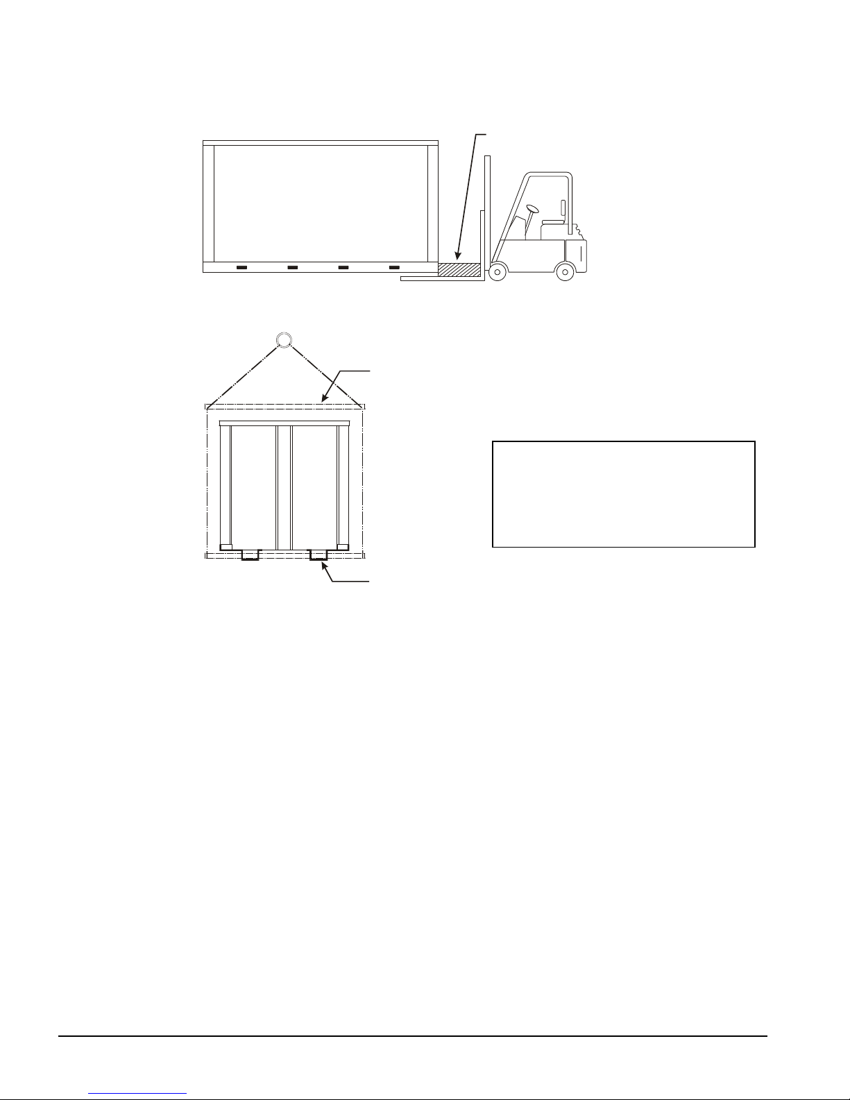
Handling
Be careful to avoid rough handling of the unit. Do not push or pull the unit from anything
other than the base. Block the pushing vehicle away from the unit to prevent damage to the
sheet-metal cabinet and end frame (see Figure 1).
To lift the unit, lifting slots are provided in the base of the unit. Arrange spreader bars and
cables to prevent damage to the condenser coils or cabinet (see Figure 2).
H
AZARD IDENTIFICATION INFORMATION
!
WARNING
Warnings indicate potentially hazardous situations, which can result in property damage, severe
personal injury, or death if not avoided.
!
CAUTION
Cautions indicate potentially hazardous situations, which can result in personal injury or
IOMM AGZB1 AGZ 010B through 034B 3
equipment damage if not avoided.
Page 4
BLOCKING REQUIRED
ACROSS FULL WIDTH
SPREADER BAR (2)
PIPE SLUNG THRU
OPENINGS IN LEGS (2)
Figure 1, Suggested Pushing Arrangement
Figure 2, Suggested Lifting Arrangement
NOTE:: The fork lift slots can be used for
lifting by inserting sufficiently strong pipe
through them as shown in Figure 2.
Use the outboard slots on three-fan units
and the only two on two-fan units.
Location
Unit Placement
AGZ units are for outdoor applications and can be mounted on a roof or at ground level.
Set units on a solid and level foundation. For roof-mounted applications, install the unit on
a steel channel or I-beam frame to support the unit above the roof. For ground level
applications, install the unit on a substantial base that will not settle. A one-piece concrete
slab with footings extended below the frost line is recommended. Be sure the foundation is
level (within 1/2” [13 mm] over its length and width). The foundation must support the
operating weights listed in the Physical Data Tables on pages 16 and 17. It is recommended
that the unit be raised a few inches with a suitable support, located at least under the
mounting locations, to allow water to drain from under the unit and to facilitate cleaning
under it.
Since its operation is affected by wind, the unit should be located so that its length is
parallel with the prevailing wind. If this is not practical, use field fabricated wind
deflectors.
Service Access
Each end of the unit must be accessible after installation for periodic service. Compressors,
filter-driers, and liquid line solenoid valve are accessible from the end of the unit. Highpressure, low-pressure, and motor protector controls are on the compressor. Most
operating, equipment protection, and starting controls are located in the unit control box.
4 AGZ 010B through 034B IOMM AGZB1
Page 5
The fan deck with the condenser fans and motors can be removed from the top of the unit.
4 Ft.
Clearance for Air Inlet
Clearance for Air Inlet
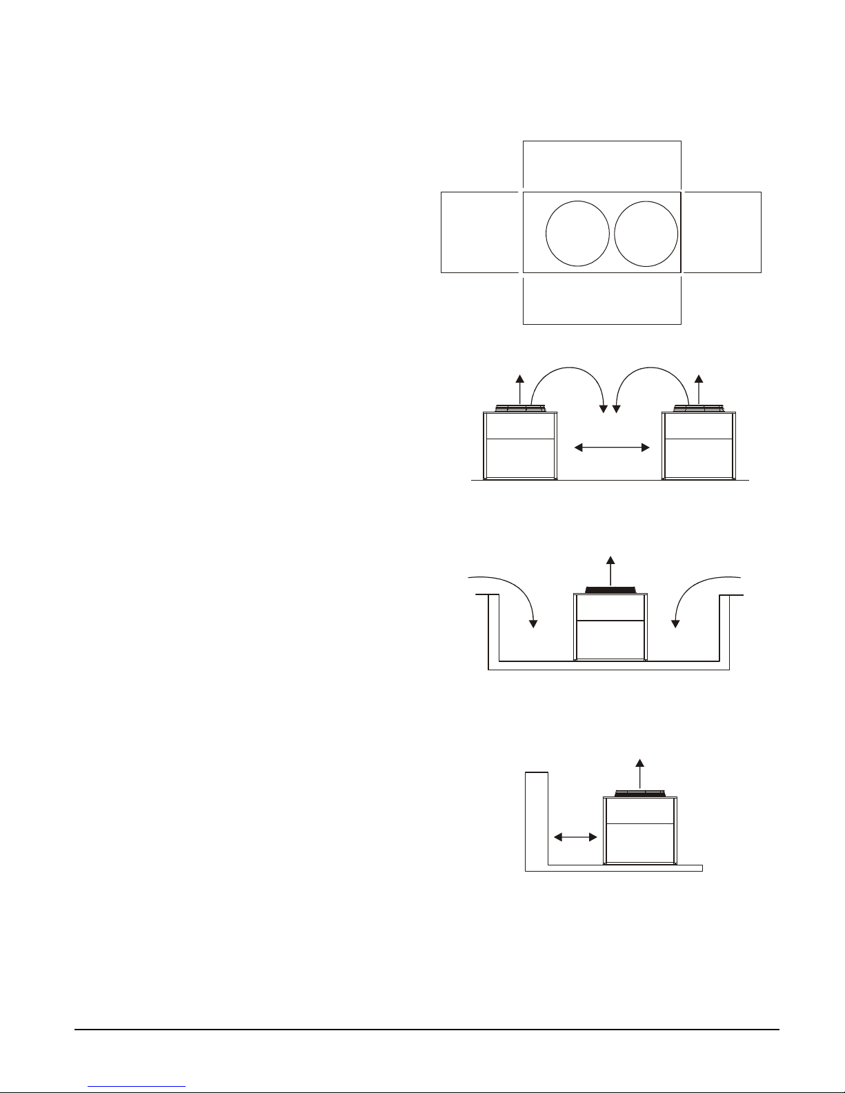
The recommended minimum side clearance between two units
The unit must not be installed in a pit or enclosure that is
deeper or taller than the height of the unit unless extra space
unit is 6 feet (1828mm) when installed in a pit. The pit cannot
Clearances
The flow of air to and from the
condenser coil must not be limited.
Restricting airflow or allowing air
recirculation will result in a decrease in
unit performance and efficiency. There
must be no obstruction above the unit
that would deflect discharge air
downward where it could be
recirculated back to the inlet of the
condenser coil. The condenser fans are
propeller type and will not operate with
ductwork on the fan outlet.
Install the unit with enough side
clearance for air entrance to the coil
and for servicing. Provide service access to
the evaporator, compressors, electrical
control panel and piping components as
shown in Figure 3. Do not block access to
the unit with piping or conduit.
Do not allow debris to accumulate near the
unit. Air movement may draw debris into
the condenser coil causing air starvation.
Give special consideration to low ambient
operation where snow can accumulate.
Keep condenser coils and fan discharge
free of snow or other obstructions to permit
adequate airflow.
Figure 3, Clearance requirements
4 Ft. (1220mm)
(1220mm)
Clearance for
Service Access
4 Ft. (1220mm)
is 8 feet (2440mm).
4 Ft.
(1220mm)
Clearance for
Service Access
Sound Isolation
The low sound levels of the AGZ chiller
are suitable for most applications. When
additional sound reduction is necessary,
locate the unit away from sound sensitive
areas. Avoid locations beneath windows or
between structures where normal operating
sounds may be objectionable. Reduce
structurally transmitted sound by isolating
water lines, electrical conduit and the unit
itself. Use wall sleeves and rubber isolated
piping hangers to reduce transmission of
water or pump noise into occupied spaces.
Use flexible electrical conduit to isolate
sound through electrical conduit. Spring
isolators are effective in reducing the low
amplitude sound generated by the Discus
semi-hermetic compressors and for unit
isolation in sound-sensitive areas.
is provided. The minimum clearance on each side of the
be deeper than the unit.
The minimum clearance to a side wall or building taller than
the unit height is 6 feet (1828mm) provided no solid wall
above 6 feet (1828mm) tall is closer than 12 feet (3658mm)
to the opposite side of the unit.
IOMM AGZB1 AGZ 010B through 034B 5
Page 6
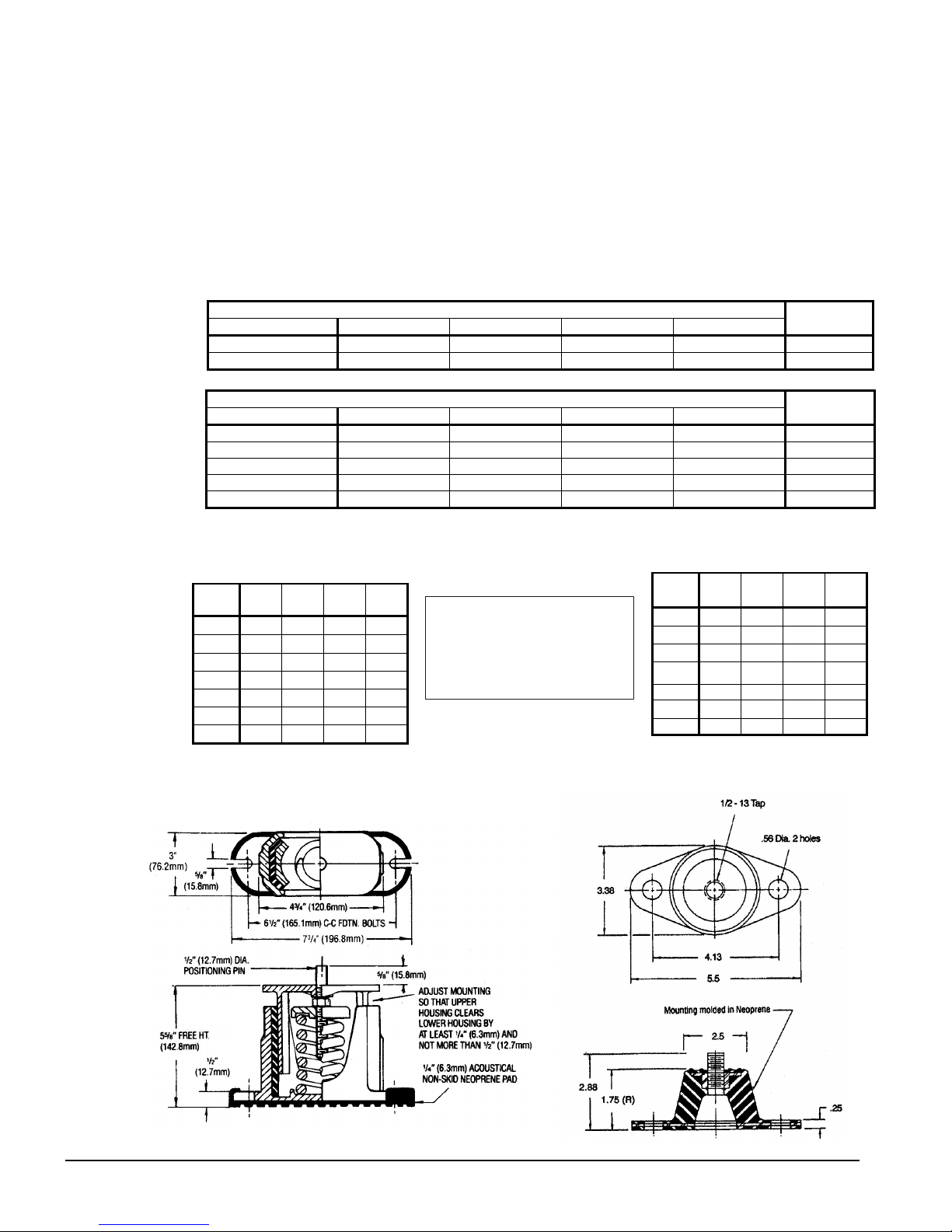
Vibration Isolators
Vibration isolators are recommended for all roof-mounted installations or wherever vibration
transmission is a consideration.
The unit should be initially placed on shims or blocks at the listed free height. When all
piping, wiring, flushing, charging, etc. is completed, the springs are adjusted upward to
loosen the blocks or shims that are then removed.
A rubber anti-skid pad is part of the isolator. Installation of spring isolators requires flexible
piping connections and at least three feet of flexible conduit to avoid straining the piping and
transmitting vibration and noise. These units cannot be bolted to isolators.
Table 1, Recommended Vibration Isolators
Neoprene-in-Shear
AGZ Model RF LF RB LB
010, 013, 017 RP-3 Red RP-3 Red RP-3 Red RP-3 Red 350014858
020, 025, 029, 034 RP-3 Green RP-3 Green RP-3 Red RP-3 Red 350014857
Spring
AGZ Mod el RF LF RB LB
010 CP 1-24 Brown CP 1-24 Brown CP 1-24 Brown CP 1-24 Brown 3500148 32
013, 017 CP 1-25 Red CP 1-25 Red CP 1-25 Red CP 1-25 Red 3500148 34
020, 025 CP1-26 Purple CP1-27 Orange CP 1-24 Brown CP 1-24 Brown 3500148 36
029 CP1-27 Orange CP1-2 7 Orange CP 1-25 Red CP 1-25 Red 3500148 38
034 CP1-27 Orange CP1 -2 8 Green CP 1-25 Red CP 1-25 Red 350014840
Note: See dimension drawing for location of isolators
Kit P/N
Kit P/N
Corner Weights
Packaged Chiller
AGZ-
010A
013A
017A
020A
025A
029A
034A
RF LF RB LB
BS
279 275 267 263
315 297 288 271
344 323 316 297
502 475 271 257
531 496 301 282
583 238 353 326
779 761 369 361
R BI
L BI
Control
Panel
R FI
L FI
Remote Evaporator
AGZ-
010A
013A
017A
020A 446 443 241 240
025A
029A
034A
LF RF LB RB
BM
257 264 236 243
290 286 246 243
312 309 266 263
453 449 245 243
488 487 296 295
656 703 297 318
CP-1, Spring Isolator RP-3 Neoprene-in-Shear Isolator
6 AGZ 010B through 034B IOMM AGZB1
Page 7
Chilled Water System
Water Piping
Local authorities can supply the installer with the proper building and safety codes required
for proper installation.
Install piping with minimum bends and changes in elevation to minimize pressure drop.
Consider the following when installing water piping:
1. Vibration eliminators to reduce vibration and noise transmission to the building.
2. Shutoff valves to isolate the unit from the piping system during unit servicing.
3. Manual or automatic air vent valves at the high points of the system. Install drains at
the lowest points in the system.
4. Maintaining adequate system water pressure (expansion tank or regulating valve).
5. Temperature and pressure indicators located at the unit to aid in unit servicing.
Pressure gauge taps must be installed in the chilled water inlet and outlet piping or as
shown in Figure 4.
6. A strainer or other means of removing foreign matter from the water before it enters the
pump. Place the strainer far enough upstream to prevent cavitation at the pump inlet
(consult pump manufacturer for recommendations). The use of a strainer can prolong
pump life and keep system performance up.
7. A 40-mesh strainer is required in the water line just before the inlet of the evaporator.
This will help prevent foreign material from entering and decreasing the performance
of the evaporator.
!
CAUTION
If a separate disconnect is used for the 110V supply to the evaporator heating cable,
mark the disconnect clearly so the disconnect is not accidentally shut off during cold
seasons. Failure to do so can cause a failure of the evaporator.
8. The brazed plate evaporator has a thermostat and heating cable to prevent freeze-up
down to -20°F (-29°C). The heating cable should be wired to a separate 110V supply
circuit. As shipped from the factory, the heating cable is wired to the control circuit.
Protect all water piping to the unit from freezing.
9. If the unit is used as a replacement chiller on a previously existing piping system, flush
the system thoroughly before unit installation. Perform regular water analysis and
chemical water treatment on the evaporator immediately at equipment start-up.
10. When glycol is added to the water system for freeze protection, the refrigerant suction
pressure will be lower, cooling performance less, and water side pressure drop greater.
If the percentage of glycol is high, or if propylene is used instead of ethylene glycol, the
added pressure drop and loss of performance could be substantial. Reset the freezestat
and low leaving water alarm temperatures. The freezestat is factory set to default at
38°F (3.3°C). Reset the freezestat setting to approximately 4 to 5 degrees F (2.3 to 2.8
degrees C) below the leaving chilled water setpoint temperature. See the section titled
“Glycol Solutions” on page 10 for additional information concerning glycol.
11. Perform a preliminary leak check before insulating the piping and filling the system.
12. Include a vapor barrier on the piping insulation to prevent condensation and possible
damage to the building structure.
IOMM AGZB1 AGZ 010B through 034B 7
Page 8
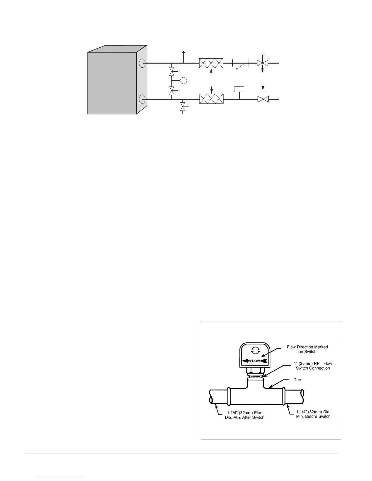
Figure 4, Typical Field Evaporator Water Piping
Air
Flow
Switch
Vibration
Eliminators
Drain
Isolation
Strainer
Vent
Inlet
P
Outlet
Valves
NOTES:
1. Chilled water piping within the unit enclosure must be insulated in the field.
2. Support piping independently of the unit and install per local codes.
System Volume
It is important to have adequate water volume in the system to provide an opportunity for
the chiller to sense a load change, adjust to the change and stabilize. As the expected load
change becomes more rapid, a greater water volume is needed. The system water volume is
the total amount of water in the evaporator, air handling products and associated piping. If
the water volume is too low, operational problems can occur, including rapid compressor
cycling, rapid loading and unloading of compressors, erratic refrigerant flow in the chiller,
improper motor cooling, shortened equipment life and other undesirable occurrences.
For normal comfort cooling applications, where the cooling load changes relatively slowly,
we recommend a minimum system volume of three to four times the flow rate (GPM). For
example, if the design chiller flow rate is 120 GPM, we recommend a minimum system
volume of 360 to 480 gallons.
Since there are many other factors that can influence performance, systems may
successfully operate below these suggestions. However, as the water volume decreases
below these suggestions, the possibility of problems increases.
Variable Chilled Water flow
Variable chilled water flow systems are not recommended for this class of equipment due to
limited unloading capability.
Flow Switch
Mount a water flow switch in the leaving water line to shut down the unit when water flow
is interrupted.
A flow switch is available from
McQuay (part number 017503300). It
is a “paddle” type switch and adaptable
to pipe sizes down to 1 1/4” (32mm)
nominal. Certain minimum flow rates
are required to close the switch and are
listed in Table 2. Install the switch as
shown in Figure 5. Connect the
normally open contacts of the flow
switch in the unit control center at
terminals 4 and 5. There is also a set of
normally closed contacts on the switch
that can be used for an indicator light or
an alarm to indicate when a “no-flow”
Figure 5, Flow Switch Installation
8 AGZ 010B through 034B IOMM AGZB1
Page 9
condition exists. Freeze protect any flow switch that is installed outdoors. Follow
installation instructions provided with the flow switch. Calibrate the flow switch to open at
one-half of nominal flow rate.
NOTE: Differential pressure switches are not recommended for outdoor
installation. They are subject to damage from freezing.
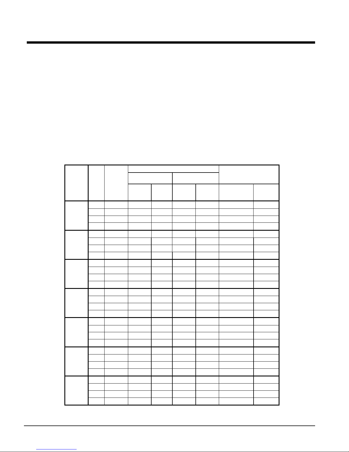
Table 2, Flow Switch Settings
(NOTE !)
Min.
Adjst.
Max.
Adjst.
Flow
Flow Lpm 0.8 1.1 2.2 2.8 4.3 11.4 22.9 35.9 38.6
Flow
Flow Lpm 2.8 4.1 6.1 7.3 11.4 27.7 53.4 81.8 90.8
NOTES:
1. A segmented 3-inch paddle (1, 2, and 3 inches) is furnished mounted, plus a 6-inch paddle loose.
2. Flow rates for a 2-inch paddle trimmed to fit the pipe.
3. Flow rates for a 3-inch paddle trimmed to fit the pipe.
4. Flow rates for a 3-inch paddle.
5. Flow rates for a 6-inch paddle.
inch 1 1/4 1 1/2 2 2 1/2 3 4 5 6 8 Pipe Size
mm 32 (2) 38 (2) 51 63 (3) 76 102 (4) 127 (4) 153 (4) 204 (5)
gpm 5.8 7.5 13.7 18.0 27.5 65.0 125.0 190.0 205.0
Lpm 1.3 1.7 3.1 4.1 6.2 14.8 28.4 43.2 46.6
gpm 3.7 5.0 9.5 12.5 19.0 50.0 101.0 158.0 170.0
No
gpm 13.3 19.2 29.0 34.5 53.0 128.0 245.0 375.0 415.0
Lpm 3.0 4.4 6.6 7.8 12.0 29.1 55.6 85.2 94.3
gpm 12.5 18.0 27.0 32.0 50.0 122.0 235.0 360.0 400.0
No
Water Connections
The unit has 3-inch holes for the chilled water piping to enter the unit. The connections are
made to the evaporator water connections located within the unit. Chilled water piping
within the unit must be insulated.
Refrigerant Charge
All units are designed for R-22 or R-407C and are shipped with an operating charge. The
operating charge for each unit is shown in the Physical Data Tables on pages 16 and 17.
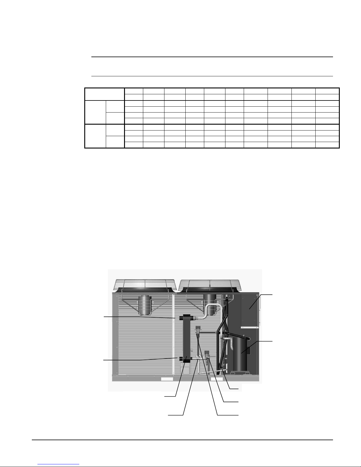
Unit Component Location
Chilled Water
Inlet Connection
Chilled Water
Outlet Connection
Evaporator
Control Panel
Tandem Scroll
Compressors
Charging Valve
Solenoid Valve, Expansion Valve
Optional Hot Gas Bypass Valve Filter Drier
IOMM AGZB1 AGZ 010B through 034B 9
Page 10

Glycol Solutions
The use of glycol antifreeze solutions will decrease unit capacity and increase the pressure
drop through the cooler. See Product Manual Catalog ACZAGZB1 for specific ratings and
correction factors.
!
CAUTION
Do not use automotive grade antifreeze. Industrial grade glycols must be used.
Automotive antifreeze contains inhibitors that will cause plating on the copper tubes within
the chiller evaporator. The type, storage, disposal, and handling of glycol used must be
consistent with local codes.
Evaporator Water Flow and Pressure Drop
Evaporator flow rate must fall between the minimum and maximum values shown in the
evaporator pressure drop curve, Figure 6. Flow rates outside of these limits result in a
chilled water Delta-T outside the operating range of the controller.
Measure the chilled water pressure drop through the evaporator at field-installed pressure
taps. It is important not to include the effect of valves or strainers in these readings.
Do not vary the chilled water flow through the evaporator while the compressors are
operating.
10 AGZ 010B through 034B IOMM AGZB1
Page 11
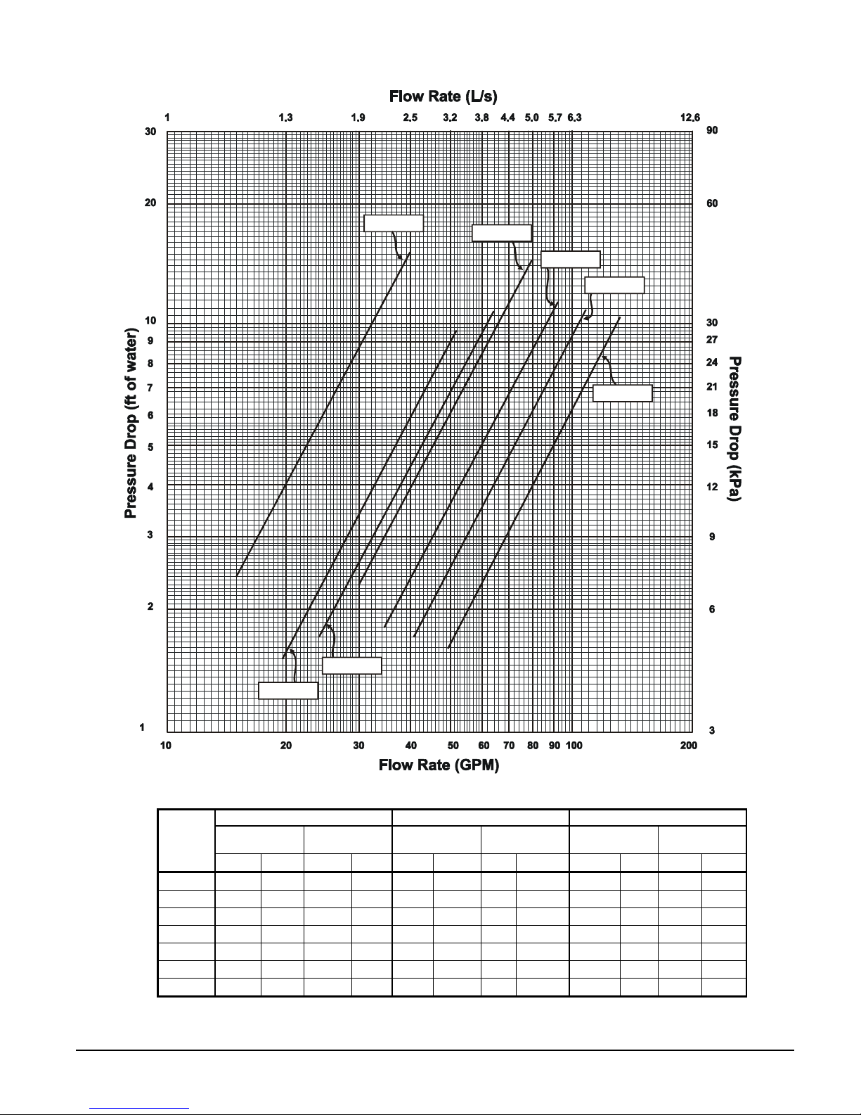
Figure 6, Evaporator Water Pressure Drop Curves
AGZ 020
AGZ 025
AGZ 029
AGZ 034
AGZ 010
AGZ 017
AGZ 013
Minimum Flow Nominal Flow Maximum Flow
AGZ
Model
010
013
017
020
025
029
034
Flow Rate
gpm L/s ft. kPa gpm L/s ft. kPa gpm L/s ft. kPa
15.0 0.9 2.4 7.1 24.0 1.5 5.8 17.3 40.0 2.5 15.2 45.5
19.5 1.2 1.5 4.5 31.2 2.0 3.7 11.0 52.0 3.3 9.6 28.9
24.0 1.5 1.7 5.0 38.4 2.4 4.1 12.2 64.0 4.0 10.7 32.1
30.0 1.9 2.3 6.8 48.0 3.0 5.6 16.7 80.0 5.0 14.5 43.4
34.5 2.2 1.8 5.3 55.2 3.5 4.3 13.0 92.0 5.8 11.4 34.3
40.7 2.6 1.7 5.0 65.0 4.1 4.0 12.1 108.4 6.8 10.9 32.6
49.8 3.1 1.6 4.7 79.7 5.0 3.9 11.7 132.8 8.4 10.4 31.2
Pressure
Drop
Flow Rate
Pressure
Drop
Flow Rate
Pressure
Drop
IOMM AGZB1 AGZ 010B through 034B 11
Page 12

R-407C Units
AGZ chillers are available with R-407C refrigerant as non-ARI certified units. R-407C is a
zeotropic blend of three compounds, and as such exhibits the characteristic of glide. It does not
behave as one substance like R-22 does. Glide is the difference (in degrees F) between the
beginning and end phase-change process in either the evaporator or condenser. During these
processes, different ratios of the refrigerant’s components change phase from the beginning to the
end of the process. The following functions, conditions and settings will differ from units
charged with R-22.
1. Different physical data and electrical data
2. Polyolester lubricants are used instead of mineral oil.
3. The saturated pressure/temperature relationship
4. Control and alarm settings
5. Charging procedures
1. Lubrication. The units are factory-charged with polyoester (POE) lubricant and one of the
following lubricants must be used if lubricant is to be added to the system:
POEs are very hygroscopic and will quickly absorb moisture if exposed to air. Pump the
lubricant into the unit through a closed transfer system. Avoid overcharging the unit.
Copeland Ultra 22 CC
Mobil EAL Arctic 22 CC
ICI EMKARATE RL RL 32CF
2. Pressure/temperature relationship. See Table 3 on page 13 for the saturated pressure-
temperature chart. Due to refrigerant glide, use the following procedures for superheat and
subcooling measurement.
To determine superheat, only vapor must be present at the point of measurement, no liquid.
Use the temperature reading, the pressure reading and the Saturated P/T Chart. If the
pressure is measured at 78 psig, the chart shows the saturated vapor temperature to be
50.6°F. If the temperature is measured at 60°F, the superheat is 9.4 degrees F.
To determine subcooling, only liquid must be present, no vapor. Use the temperature
reading, the pressure reading and the Saturated P/T Chart. If the pressure is measured at
250 psig, the chart shows the saturated liquid temperature to be 108.2°F. If the temperature
is measured at 98°F, the subcooling is 10.2 degrees F.
The P/T relationship between R-407C and R-22 is similar enough to allow the use of R-22
expansion valves. The valves may be marked as “R-22’ or “R-22/R-407C”.
3. Control and alarm settings. The software that controls the operation of the unit is factory-
set for operation with R-407C, taking into account that the pressure/temperature relationship
differs from R-22. The software functionality is the same for either refrigerant.
4. Charging procedure. The units are factory-charged with R-407C. Use the following
procedure if recharging in the field is necessary:
Whether topping off a charge or replacing the circuit’s entire charge, always remove the
refrigerant from the charging vessel as a liquid. Many of the cylinders for the newer
refrigerants have a dip tube so that liquid is drawn off when the cylinder is in the upright
position. Do not vapor charge out of a cylinder unless the entire contents will be charged
into the system.
With the system in a 250-micron or lower vacuum, liquid can be charged into the high side.
Initially charge about 80 percent of the system total charge.
12 AGZ 010B through 034B IOMM AGZB1
Page 13
Start the system and observe operation. Use standard charging procedures (liquid only) to
top off the charge.
It may be necessary to add refrigerant through the compressor suction. Because the
refrigerant leaving the cylinder must be a liquid, exercise care to avoid damage to the
compressor. A sight glass can be connected between the charging hose and the compressor.
It can be adjusted to have liquid leave the cylinder and vapor enter the compressor.
Table 3, R-407C Pressure/Temperature Chart
Pressure
(PSIG)
20 -10.7 1.5 150 74.8 84.9
22 -8.2 4.0 155 76.8 86.8
24 -5.7 6.4 160 78.7 88.7
26 -3.4 8.7 165 80.6 90.5
28 -1.1 11.0 170 82.5 92.3
30 1.1 13.1 175 84.3 94.0
32 3.2 15.2 180 86.1 95.8
34 5.3 17.2 185 87.8 97.5
36 7.3 19.2 190 89.6 99.1
38 9.2 21.0 195 91.3 100.7
40 11.1 22.9 200 92.9 102.3
42 12.9 24.7 205 94.6 103.9
44 14.7 26.4 210 96.2 105.4
46 16.4 28.1 215 97.7 107.0
48 18.1 29.7 220 99.3 108.4
50 19.7 31.3 225 100.8 109.9
52 21.3 32.9 230 102.3 111.4
54 22.9 34.4 235 103.8 112.8
56 24.4 35.9 240 105.3 114.2
58 25.9 37.4 245 106.7 115.6
60 27.4 38.8 250 108.2 116.9
62 28.8 40.2 255 109.6 118.2
64 30.2 41.6 260 111.0 119.6
66 31.6 43.0 265 112.3 120.9
68 33.0 44.3 270 113.7 122.1
70 34.3 45.6 275 115.0 123.4
72 35.6 46.9 280 116.3 124.7
74 36.9 48.1 285 117.6 125.9
76 38.2 49.3 290 118.9 127.1
78 39.4 50.6 295 120.2 128.3
80 40.6 51.8 300 121.4 129.5
82 41.9 52.9 305 122.7 130.7
84 43.0 54.1 310 123.9 131.8
86 44.2 55.2 315 125.1 133.0
88 45.4 56.3 320 126.3 134.1
90 46.5 57.4 325 127.5 135.2
92 47.6 58.5 330 128.7 136.3
94 48.7 59.6 335 129.8 137.4
96 49.8 60.7 340 131.0 138.5
98 50.9 61.7 345 132.1 139.6
100 51.9 62.7 350 133.2 140.6
105 54.5 65.2 355 134.3 141.7
110 57.0 67.7 360 135.4 142.7
115 59.5 70.0 365 136.5 143.7
120 61.8 72.3 370 137.6 144.7
125 64.1 74.6 375 138.7 145.7
130 66.4 76.7 380 139.8 146.7
135 68.5 78.8 385 140.8 147.7
140 70.7 80.9 390 141.8 148.7
145 72.8 82.9 395 142.9 149.6
Liquid Temp
(°F)
Vapor Temp
(°F)
Pressure
(PSIG)
Liquid Temp
(°F)
Vapor Temp
(°F)
IOMM AGZB1 AGZ 010B through 034B 13
Page 14
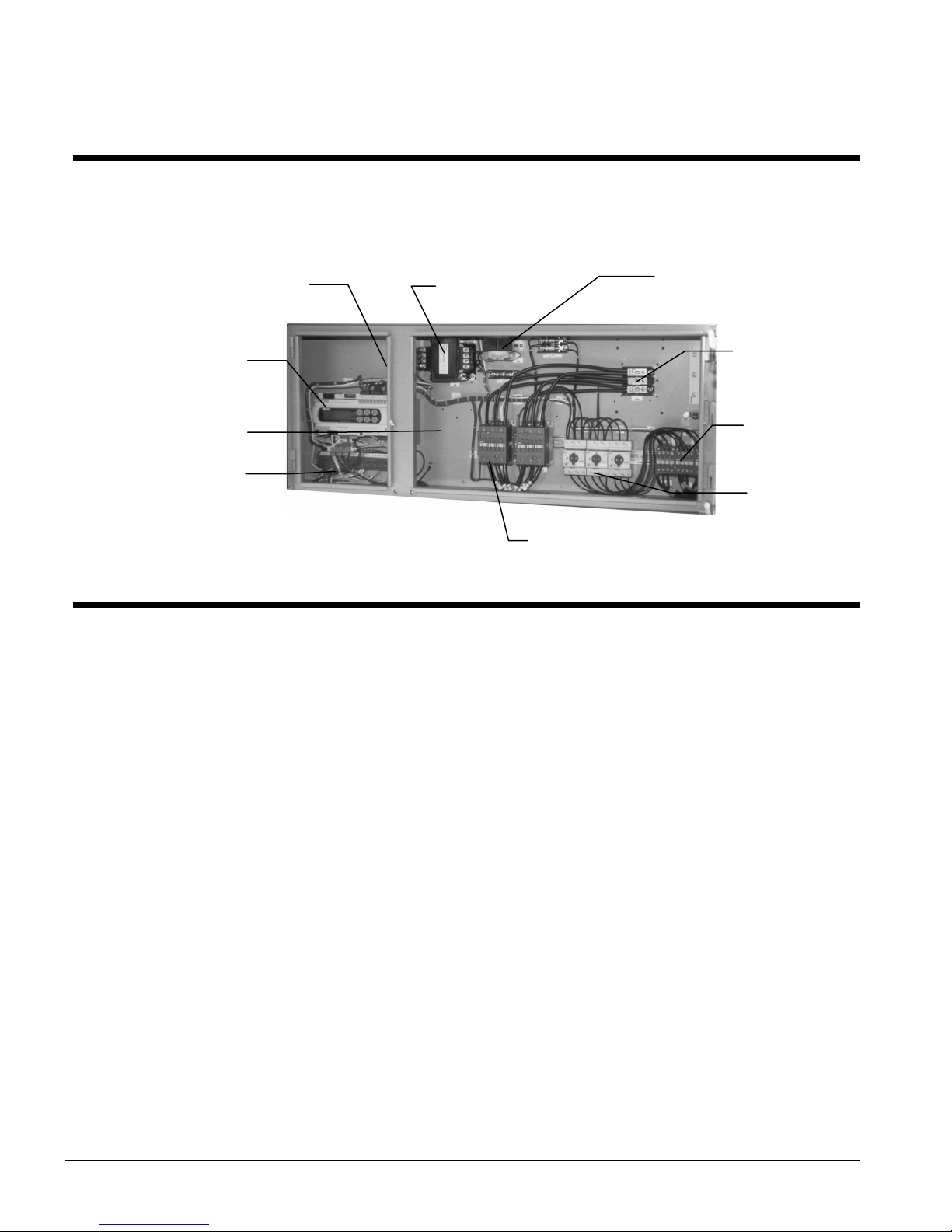
Control Layout and Operation
Control Center
All electrical controls are enclosed in a weatherproof control center with tool-locked, hinged
access doors. The left-hand section contains the microprocessor controller and control input and
output terminals. All high-voltage components are located on the right side of the panel.
ON/OFF Switch
MicroTech II
Controller
SpeedTrol Location
Field Connection
Terminals
Start-up and Shutdown
Pre Start-up
1. The chilled-water system should be flushed and cleaned. Proper water treatment is required
to prevent corrosion and organic growth.
2. Open all electric disconnects and check all electric connections for tightness.
3. Inspect all water piping for flow direction and correct connections at the evaporator.
4. Verify thermostat water temperature sensor is installed in the leaving water line (supply to
building). On all AGZ units the sensor well and sensor are factory mounted.
5. Check compressor oil level. The oil level should be visible in the oil sight glass.
6. Check voltage of the unit power supply and make certain voltage is within ±10% of
nameplate rating. Check unit power supply wiring for proper ampacity and a minimum
insulation temperature of 75°C. Check for proper phasing using a phase sequence meter.
7. Verify all mechanical and electrical inspections have been completed according to local
codes.
8. Open control stop switch S1(off). Turn on the main power and control disconnect switches.
This will energize crankcase heaters. Wait at least 24 hours before starting up unit.
9. Open all water flow valves and start the chilled water pump. Check all piping for leaks and
vent the air from the evaporator as well as from the system piping. Flush the evaporator and
system piping to obtain clean, noncorrosive water in the evaporator.
Control
Transformer
24-Volt Trans.
Non-Fused Disc.
or
Power Block
Fan
Contactors
Fan
Protection
Compressor Contactors
Start-up
1. Set temperature controller to the desired chilled water temperature. Set the chilled water
Delta-T.
14 AGZ 010B through 034B IOMM AGZB1
Page 15

2. Start auxiliary equipment by turning on the following: time clock (if present), ambient
thermostat and/or remote on/off switch, chilled water pump.
3. If the controller calls for cooling, the unit will begin the start-up sequence.
4. After running the unit for a short time, check the oil level in the compressor (1/4 to 1/3
of the glass), rotation of fans, and flashing in refrigerant sight glass.
5. Verify superheat temperature is at the factory setting of 8 to 12 degrees F (4.4 to 6.7
degrees C).
6. After system performance has stabilized, complete the current AGZ Start-Up Form
(obtainable from the local McQuay sales office) to establish inception of warranty
benefits. Return the form to McQuay International through your sales representative.
Sequence of Operation
Start-Up
With the control circuit power on, 115V power is applied through the control circuit fuse F1
to the compressor crankcase heaters, the compressor motor protections and the primary of
the 24V control circuit transformer. The 24V transformer provides power to the
microprocessor controller.
When a remote time clock, manual switch, or the unit controller turns on the chilled water
pump, the flow switch closes and satisfies the flow requirement. If the chilled water
temperature is above the stage-on temperature, and all equipment protection devices are
closed, the unit will start. The controller will operate the unit in response to the leaving
chiller water temperature or reset signals that may be present.
Equipment Protection Alarms
The following conditions will shut down the unit and activate the alarm circuit:
• No evaporator water flow • Low evaporator pressure
• High condenser pressure • Motor protection system
• Phase voltage protection (Optional) • Outside ambient temperature
• Evaporator freeze protection • Sensor failures
The following alarms will limit unit operation:
• Condenser pressure stage down, unloads unit at high discharge pressures
• Low ambient lockout, shuts off unit at low ambient temperatures
• Low evaporator pressure hold, holds stage #1 until pressure rises
• Low evaporator pressure unload, shuts off stage #2
Unit Enable Selection
Enables unit operation from local keypad, digital input, or Building Automation System.
Unit Mode Selection
Selects standard cooling, ice, glycol, or test operation mode.
Condenser fan control
Control of condenser fans is provided by the MicroTech II controller. The control steps
condenser fans based on discharge pressure.
Shutdown
As the leaving water control is satisfied, it will stage off the lag compressor unloading the
unit. The second stage will de-energize the liquid line solenoid valve SV1 and shut off the
lead compressor. The compressor crankcase heaters will energize when the compressors
shut off, keeping the small amount of refrigerant in the plate heat exchanger from migrating
to the compressor. See page 56 for detailed explanation of compressor staging.
IOMM AGZB1 AGZ 010B through 034B 15
Page 16
Physical Data
AGZ-BS, R-22/R-407C
Table 4, Physical Data, AGZ 010BS through 017BS, Packaged, R-22/R-407C
PHYSICAL DATA
BASIC DATA
Unit Capacity @ ARI Conditions (1), Tons (kW) 10.0 (36.2) 13.7 (48.2) 15.8 (55.6)
Number Of Refrigerant Circuits 1 1 1
Unit Operating Charge, R-22 and R-407C, Lb. (kg) 22.0 (10.0) 24.0 (10.9) 31.0 (14.1)
Cabinet Dimensions, LxWxH, In. 73.6 x 46.3 x 50.8 73.6 x 46.3 x 50.8 73.6 x 46.3 x 50.8
Cabinet Dimensions, LxWxH, (mm) (1869) x (1176) x (1289) (1869) x (1176) x (1289) (1869) x (1176) x (1289)
Unit Operating Weight, Lb. (kg) 1095 (498) 1190 (541) 1300 (591)
Unit Shipping Weight, Lb. (kg) 1085 (493) 1170 (532) 1280 (582)
Add'l Weight If Copper Finned Coils, Lb. (kg)
R-22 and [R-407C]
COMPRESSORS
Type Scroll Scroll Scroll
Nominal Horsepower 6.0 / 6.0 7.5 / 7.5 9.0 / 9.0
Oil Charge Per Compressor of a Tandem Set, oz. (g) 60 (1701) 85 (2410) 110 (3119)
CAPACITY REDUCTION STEPS - PERCENT OF COMPRESSOR DSPLACEMENT
Standard Staging 0 – 50 – 100 0 – 50 – 100 0 – 50 – 100
CONDENSERS - HIGH EFFICIENCY FIN AND TUBE TYPE WITH INTEGRAL SUBCOOLING
Coil Face Area, One of Two Sides, Sq. Ft. (M2) 30.3 (2.8) 30.3 (2.8) 30.3 (2.8)
Finned Height x Finned Length, In. 84 x 52 84 x 52 84 x 52
Finned Height x Finned Length, (mm) (2134) x (1321) (2134) x (1321) (2134) x (1321)
Fins Per Inch x Rows Deep: R-22 and [R-407C] 16 x 2 [16 x 2] 16 x 2 [16 x 2] 16 x 3 [16 x 3]
Pumpdown Capacity Lb. (kg) 35.3 (16.0) 35.3 (16.0) 52.9 (24.0)
CONDENSER FANS - DIRECT DRIVE PROPELLER TYPE
Number Of Fans - Fan Diameter, In. (mm) 2 – 26 (660) 2 – 26 (660) 2 – 26 (660)
Number Of Motors - HP (kW) 2 – 1.0 (0.75) 2 – 1.0 (0.75) 2 – 1.0 (0.75)
Fan And Motor RPM, 60 Hz 1140 1140 1140
60 Hz Total Unit Airflow, CFM (l/s) 13950 (6584) 13950 (6584) 12000 (5664)
DIRECT EXPANSION EVAPORATOR - BRAZED PLATE-TO-PLATE
Connection Size Victaulic, In. (mm) 2 (51) 2 (51) 2 (51)
Water Volume, Gallons (L) .94 (3.6) 1.66 (6.3) 2.00 (7.6)
Maximum Refrigerant Working Pressure, psig (kPa) 450 (3103) 450 (3103) 450 (3103)
Maximum Water Pressure, psig (kPa) 350 (2413) 350 (2413) 350 (2413)
NOTE: Nominal capacity based on 95°F ambient air and 54°F/44°F water range.
010B 013B 017B
176 (80.0)
[176 (80.0)]
AGZ MODEL NUMBER
176 (80.0)
[176 (80.0)]
264 (120.0)
[264 (120.0)]
16 AGZ 010B through 034B IOMM AGZB1
Page 17
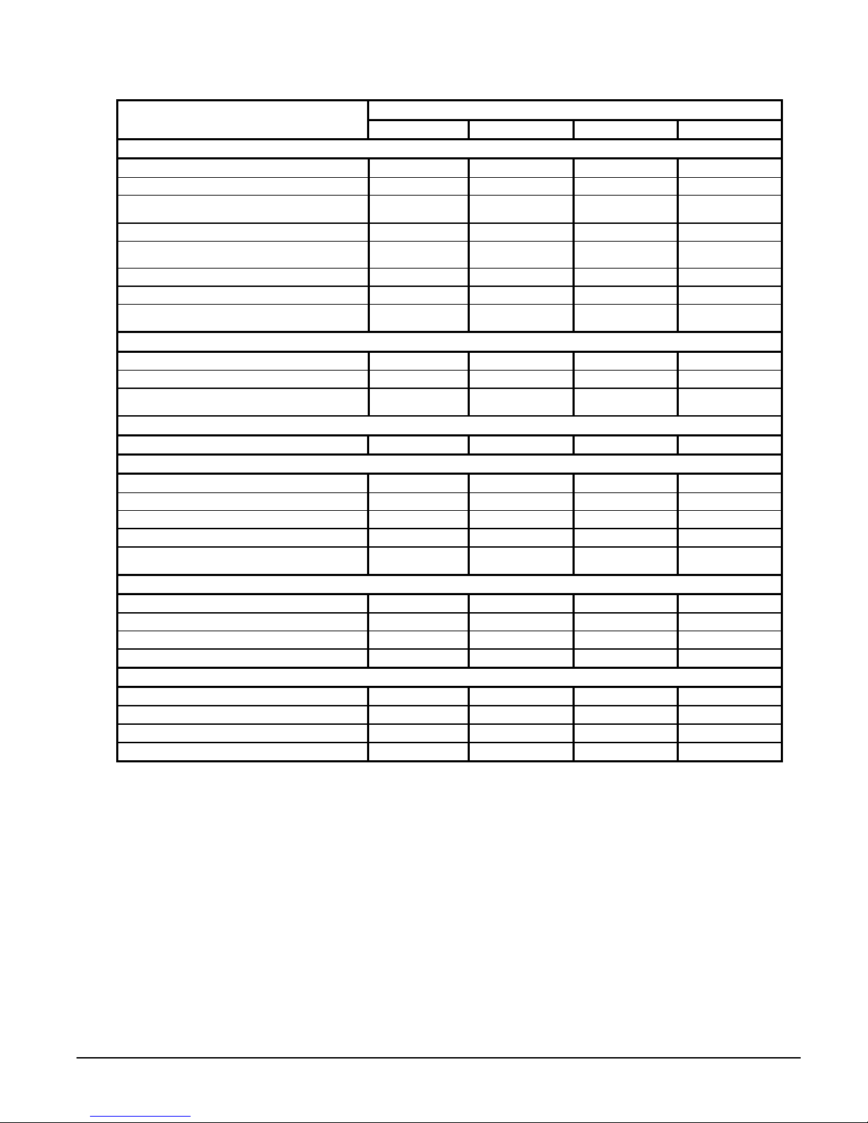
Table 5, Physical Data, AGZ 020BS through 034BS, Packaged, R-22/R-407c
PHYSICAL DATA
BASIC DATA
Unit Capacity @ ARI Conditions (1), Tons (kW) 20.6 (72.4) 22.7 (79.8) 27.7 (97.5) 34.0 (119.5)
Number Of Refrigerant Circuits 1 1 1 1
Unit Operating Charge, R-22 and [R-407C],
Lb. (kg)
Cabinet Dimensions, LxWxH, In. 106.2x 46.3 x 50.8 106.2x 46.3 x 50.8 106.2x 46.3 x 58.8 106.2x 46.3 x 58.8
Cabinet Dimensions, LxWxH, (mm)
Unit Operating Weight, Lbs. (kg) 1590 (723) 1635 (743) 1830 (832) 2315 (1052)
Unit Shipping Weight, Lbs. (kg) 1570 (714) 1610 (732) 1800 (818) 2270 (1032)
Add'l Weight If Copper Finned Coils, Lb. (kg)
R-22 and [R-407C]
COMPRESSORS
Type Scroll Scroll Scroll Scroll
Nominal Horsepower 12.0 / 12.0 13.0 / 13.0 15.0 / 15.0 20.0 / 20.0
Oil Charge Per Compressor of a Tandem Set,
oz. (g)
CAPACITY REDUCTION STEPS - PERCENT OF COMPRESSOR DISPLACEMENT
Standard Staging 0 –50 - 100 0 – 50 – 100 0 – 50 – 100 0 – 50 – 100
CONDENSERS - HIGH EFFICIENCY FIN AND TUBE TYPE WITH INTEGRAL SUBCOOLING
Coil Face Area, One of Two Sides, Sq. Ft. (M2) 49.0 (4.6) 49.0 (4.6) 58.3 (5.4) 58.3 (5.4)
Finned Height x Finned Length, In. 84 x 84 84 x 84 100 x 84 100 x 84
Finned Height x Finned Length, (mm) (2134) x (2134) (2134) x (2134) (2545 ) x (2134) (2545 ) x (2134)
Fins Per Inch x Rows Deep: R22 and [R407C]
Pumpdown Capacity, R-22 and [R-407C]
Lb. (kg)
CONDENSER FANS - DIRECT DRIVE PROPELLER TYPE
Number Of Fans - Fan Diameter, In. (mm) 3 – 26 (660) 3 – 26 (660) 3 – 26 (660) 3 – 26 (660)
Number Of Motors - HP (kW) 3 – 1.0 (0.75) 3 – 1.0 (0.75) 3 – 1.0 (0.75) 3 – 1.0 (0.75)
Fan And Motor RPM, 60 Hz 1140 1140 1140 1140
60 Hz Total Unit Airflow, CFM (l/s) 20925 (9877) 20925 (9877) 19800 (9346) 19800 (9346)
DIRECT EXPANSION EVAPORATOR - BRAZED PLATE-TO-PLATE
Connection Size Victaulic, In. (mm) 2 (51) 2 (51) 2 (51) 2 (51)
Water Volume, Gallons (L) 2.16 (8.2) 3.05 (11.5) 4.00 (15.1) 5.55 (21.0)
Max. Refrigerant Working Pressure, psig (kPa) 450 (3103) 450 (3103) 450 (3103) 450 (3103)
Maximum Water Pressure, psig (kPa) 350 (2413) 350 (2413) 350 (2413) 350 (2413)
NOTE: Nominal capacity based on 95°F ambient air and 54°F/44°F water range.
020B 025B 029B 034B
34.0 (15.4)
[38.0 (17.3)]
(2697) x (1176) x
(1289)
284 (129)
[426 (194)]
110 (3119) 110 (3119) 110 (3119) 158 (4479)
16 x 2 [16 x 3] 16 x 3 [16 x 3] 16 x 3 [16 x 3] 16 x 3 [16 x 3]
56.9 (25.9)
[85.4 (38.8)]
AGZ MODEL NUMBER
42.0 (19.1) 47.0 (21.3) 50.0 (22.7)
(2697) x (1176) x
(1289)
426 (194)
[426 (194)]
85.4 (38.8) 101.6 (46.2) 101.6 (46.2)
(2697) x (1176) x
(1493)
508 (231)
[508 (231)]
(2697) x (1176) x
(1493)
508 (231)
[508 (231)]
IOMM AGZB1 AGZ 010B through 034B 17
Page 18
AGZ-BM, R-22/R-407C
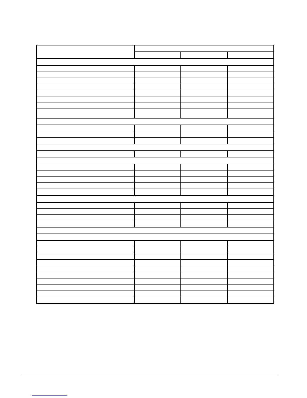
Table 6, Physical Data, AGZ 010BM through 017BM, Remote Evaporator, R-22/R-407C
PHYSICAL DATA
BASIC DATA
Unit Capacity @ ARI Conditions (1), Tons (kW) 10.0 (36.2) 13.7 (48.2) 15.8 (55.6)
Number Of Refrigerant Circuits 1 1 1
Unit Operating Charge, R-22 and[R-407C, Lb. (kg) 13 (5.9) 14 (5.3) 17 (7.7)
Cabinet Dimensions, LxWxH, In. 73.6 x 46.3 x 50.8 73.6 x 46.3 x 50.8 73.6 x 46.3 x 50.8
Cabinet Dimensions, LxWxH, (mm) (1869) x (1176) x (1289) (1869) x (1176) x (1289) (1869) x (1176) x (1289)
Unit Operating Weight, Lb. (kg) 950 (431) 1276 (579) 1278 (580)
Unit Shipping Weight, Lb. (kg) 1025 (465) 1350 (613) 1363 (619)
Add'l Weight If Copper Finned Coils, Lb. (kg)
R-22 and [R-407C]
COMPRESSORS
Type Scroll Scroll Scroll
Nominal Horsepower 6.0 / 6.0 7.5 / 7.5 9.0 / 9.0
Oil Charge Per Compressor of a Tandem Set, oz. (g) 60 (1701) 85 (2410) 110 (3119)
CAPACITY REDUCTION STEPS - PERCENT OF COMPRESSOR DSPLACEMENT
Standard Staging 0 – 50 – 100 0 – 50 – 100 0 – 50 – 100
CONDENSERS - HIGH EFFICIENCY FIN AND TUBE TYPE WITH INTEGRAL SUBCOOLING
Coil Face Area, One of Two Sides, Sq. Ft. (M2) 30.3 (2.8) 30.3 (2.8) 30.3 (2.8)
Finned Height x Finned Length, In. 84 x 52 84 x 52 84 x 52
Finned Height x Finned Length, (mm) (2134) x (1321) (2134) x (1321) (2134) x (1321)
Fins Per Inch x Rows Deep: R-22 and [R-407C] 16 x 2 [16 x 2] 16 x 2 [16 x 2] 16 x 3 [16 x 3]
Pumpdown Capacity Lb. (kg) 35.3 (16.0) 35.3 (16.0) 52.9 (24.0)
CONDENSER FANS - DIRECT DRIVE PROPELLER TYPE
Number Of Fans - Fan Diameter, In. (mm) 2 – 26 (660) 2 – 26 (660) 2 – 26 (660)
Number Of Motors - HP (kW) 2 – 1.0 (0.75) 2 – 1.0 (0.75) 2 – 1.0 (0.75)
Fan And Motor RPM, 60 Hz 1140 1140 1140
60 Hz Total Unit Airflow, CFM (l/s) 13950 (6584) 13950 (6584) 12000 (5664)
REMOTE DIRECT EXPANSION EVAPORATOR - BRAZED PLATE-TO-PLATE
Water Connection Size Victaulic, In. (mm) 2 (51) 2 (51) 2 (51)
Water Volume, Gallons (L) .94 (3.6) 1.66 (6.3) 2.00 (7.6)
Liquid Line Conn. Braze, inches 1.125 1.125 1.125
Suction Line Conn. Braze, Inches 2.125 2.125 2.125
Temperature Sensor Conn. NPT, Inches 0.75 0.75 0.75
Dry Weight, lbs (kg) 50 (22) 75 (34) 87 (39)
Operating Weight, lbs (kg) 58 (26) 88 (40) 109 (49)
Maximum Refrigerant Working Pressure, psig (kPa) 450 (3103) 450 (3103) 450 (3103)
Maximum Water Pressure, psig (kPa) 450 (3103) 450 (3103) 450 (3103)
Vent and Drain Conn. Field Field Field
NOTE: Nominal capacity based on 95°F ambient air and 54°F/44°F water range and does not take field-installed lines into account.
010B 013B 017B
176 (80.0)
[176 (80.0)]
AGZ MODEL NUMBER
176 (80.0)
[176 (80.0)]
264 (120.0)
[264 (120.0)]
18 AGZ 010B through 034B IOMM AGZB1
Page 19
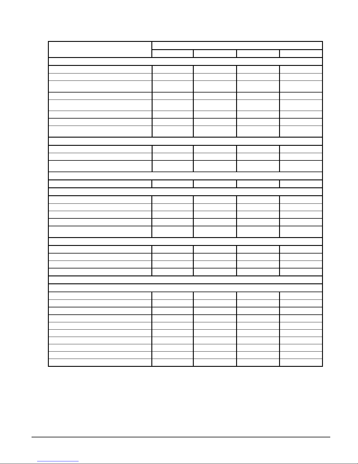
Table 7, Physical Data, AGZ 020BM through 034BmS, Remote Evaporator, R-22/R-407c
PHYSICAL DATA
BASIC DATA
Unit Capacity @ ARI Conditions (1), Tons (kW) 20.6 (72.4) 22.7 (79.8) 27.7 (97.5) 34.0 (119.5)
Number Of Refrigerant Circuits 1 1 1 1
Unit Operating Charge, R-22 and [R-407C],
Lb. (kg)
Cabinet Dimensions, LxWxH, In. 106.2x 46.3 x 50.8 106.2x 46.3 x 50.8 106.2x 46.3 x 58.8 106.2x 46.3 x 58.8
Cabinet Dimensions, LxWxH, (mm)
Unit Operating Weight, Lbs. (kg) 1459 (662) 1478 (671) 1622 (737) 1817 (825)
Unit Shipping Weight, Lbs. (kg) 1558 (707) 1576 (716) 1719 (780) 1914 (869)
Add'l Weight If Copper Finned Coils, Lb. (kg)
R-22 and [R-407C]
COMPRESSORS
Type Scroll Scroll Scroll Scroll
Nominal Horsepower 12.0 / 12.0 13.0 / 13.0 15.0 / 15.0 20.0 / 20.0
Oil Charge Per Compressor of a Tandem Set,
oz. (g)
CAPACITY REDUCTION STEPS - PERCENT OF COMPRESSOR DISPLACEMENT
Standard Staging 0 –50 - 100 0 – 50 – 100 0 – 50 – 100 0 – 50 – 100
CONDENSERS - HIGH EFFICIENCY FIN AND TUBE TYPE WITH INTEGRAL SUBCOOLING
Coil Face Area, One of Two Sides, Sq. Ft. (M2) 49.0 (4.6) 49.0 (4.6) 58.3 (5.4) 58.3 (5.4)
Finned Height x Finned Length, In. 84 x 84 84 x 84 100 x 84 100 x 84
Finned Height x Finned Length, (mm) (2134) x (2134) (2134) x (2134) (2545 ) x (2134) (2545 ) x (2134)
Fins Per Inch x Rows Deep: R22 and [R407C]
Pumpdown Capacity, R-22 and [R-407C]
Lb. (kg)
CONDENSER FANS - DIRECT DRIVE PROPELLER TYPE
Number Of Fans - Fan Diameter, In. (mm) 3 – 26 (660) 3 – 26 (660) 3 – 26 (660) 3 – 26 (660)
Number Of Motors - HP (kW) 3 – 1.0 (0.75) 3 – 1.0 (0.75) 3 – 1.0 (0.75) 3 – 1.0 (0.75)
Fan And Motor RPM, 60 Hz 1140 1140 1140 1140
60 Hz Total Unit Airflow, CFM (l/s) 20925 (9877) 20925 (9877) 19800 (9346) 19800 (9346)
REMOTE DIRECT EXPANSION EVAPORATOR - BRAZED PLATE-TO-PLATE
Connection Size Victaulic, In. (mm) 2 (51) 2 (51) 2 (51) 2 (51)
Water Volume, Gallons (L) 2.16 (8.2) 3.05 (11.5) 4.00 (15.1) 5.55 (21.0)
Liquid Line Conn. Braze, inches 1.125 1.125 1.375 1.375
Suction Line Conn. Braze, Inches 2.125 2.125 2.125 2.125
Temperature Sensor Conn. NPT, Inches 0.75 0.75 0.75 0.75
Dry Weight, lbs (kg) 92 (42) 124 (56) 156 (71) 211 (96)
Operating Weight, lbs (kg) 110 (50) 148 (67) 188 (85) 255 (116)
Max. Refrigerant Working Pressure, psig (kPa) 450 (3103) 450 (3103) 450 (3103) 450 (3103)
Maximum Water Pressure, psig (kPa) 350 (2413) 350 (2413) 350 (2413) 350 (2413)
Drain and Vent Connections Field Field Field Field
NOTE: Nominal capacity based on 95°F ambient air and 54°F/44°F water range and does not take field-installed lines into account.
020B 025B 029B 034B
34.0 (15.4)
[38.0 (17.3)]
(2697) x (1176) x
(1289)
284 (129)
[426 (194)]
110 (3119) 110 (3119) 110 (3119) 158 (4479)
16 x 2 [16 x 3] 16 x 3 [16 x 3] 16 x 3 [16 x 3] 16 x 3 [16 x 3]
56.9 (25.9)
[85.4 (38.8)]
AGZ MODEL NUMBER
42.0 (19.1) 47.0 (21.3) 50.0 (22.7)
(2697) x (1176) x
(1289)
426 (194)
[426 (194)]
85.4 (38.8) 101.6 (46.2) 101.6 (46.2)
(2697) x (1176) x
(1493)
508 (231)
[508 (231)]
(2697) x (1176) x
(1493)
508 (231)
[508 (231)]
IOMM AGZB1 AGZ 010B through 034B 19
Page 20
Electrical Data
Field Wiring
Wiring must comply with all applicable codes and ordinances. Warranty is void if wiring is
not in accordance with specifications. Copper wire is required for all power lead
terminations at the unit.
AGZ 010A through AGZ 034A units have single point power connection. A single field
supplied fused disconnect is required. The control transformer is factory mounted.
If the evaporator heater is on a separate disconnect switch from the main unit power supply,
the unit may be shut down without defeating the freeze protection provided by the
evaporator heater.
R-22 data is located on pages 21 through 22, R-407C data in on pages 23 through 24.
R-22
Table 8, Electrical Data Single Point, R-22
AGZ
Unit
Size
010B
013B
017B
020B
025B
029B
034B
See "Electrical Notes" on page 26.
Volts
208 56 3 6 AWG 1 1.00 (25)
230 54 3 6 AWG 1 1.00 (25)
460 26 3 10 AWG
575 22 3 10 AWG
208 77 3 4 AWG 1 1.00 (25)
230 77 3 4 AWG 1 1.00 (25)
460 39 3 8 AWG 1 1.00 (25)
575 30 3 10 AWG
208 82 3 4 AWG 1 1.00 (25)
230 80 3 4 AWG 1 1.00 (25)
460 41 3 8 AWG 1 1.00 (25)
575 33 3 10 AWG
208 113 3 2 AWG 1 1.25 (32)
230 113 3 2 AWG 1 1.25 (32)
460 50 3 8 AWG 1 1.00 (25)
575 42 3 8 AWG 1 1.00 (25)
208 126 3 1 AWG 1 1.25 (32)
230 126 3 1 AWG 1 1.25 (32)
460 58 3 6 AWG 1 1.00 (25)
575 50 3 8 AWG 1 1.00 (25)
208 138 3 1/0 AWG
230 138 3 1/0 AWG
460 69 3 4 AWG 1 1.00 (25)
575 57 3 6 AWG 1 1.00 (25)
208 182 3 3/0 AWG
230 182 3 3/0 AWG
460 78 3 4 AWG 1 1.00 (25)
575 63 3 6 AWG 1 1.00 (25)
Minimum
Circuit
Ampacity
(MCA)
Field Wire
Quantity
Power Supply
Wire
Gauge
75C
Quantity
Hub (Conduit
Connection)
Nominal
Size
In. (mm)
1 1.00 (25)
1 1.00 (25)
1 1.00 (25)
1 1.00 (25)
1 1.50 (38)
1 1.50 (38)
1 2.00 (51)
1 2.00 (51)
Field Fuse
or Breaker Size
Recommended Maximum
70 70
60 70
30 30
25 25
90 100
90 100
45 50
35 40
110 110
90 100
50 50
40 40
125 150
125 150
60 60
50 50
150 150
150 150
70 70
60 60
175 175
175 175
80 90
70 70
250 250
250 250
90 100
70 80
20 AGZ 010B through 034B IOMM AGZB1
Page 21
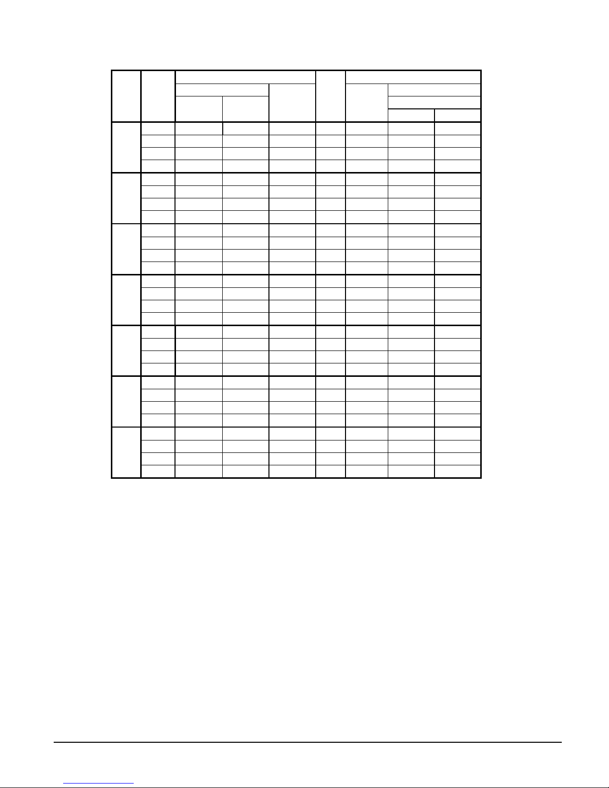
Table 9, Compressor and Condenser Fan Motor Amp Draw, R-22
AGZ
Unit
Size
010B
013B
017B
020B
025B
029B
034B
Volts
208 19.4 19.4 5.8 2 21.4 156 156
230 18.6 18.6 5.8 2 23.7 156 156
460 9.0 9.0 2.8 2 10.7 75 75
575 7.4 7.4 2.5 2 11.0 54 54
208 28.8 28.8 5.8 2 21.4 195 195
230 28.8 28.8 5.8 2 23.7 195 195
460 14.7 14.7 2.8 2 10.7 95 95
575 10.8 10.8 2.5 2 11.0 80 80
208 31.2 31.2 5.8 2 21.4 225 225
230 30.1 30.1 5.8 2 23.7 225 225
460 15.5 15.5 2.8 2 10.7 114 114
575 12.1 12.1 2.5 2 11.0 80 80
208 42.3 42.3 5.8 3 21.4 245 245
230 42.3 42.3 5.8 3 23.7 245 245
460 18.2 18.2 2.8 3 10.7 125 125
575 14.9 14.9 2.5 3 11.0 100 100
208 48.1 48.1 5.8 3 21.4 300 300
230 48.1 48.1 5.8 3 23.7 300 300
460 21.8 21.8 2.8 3 10.7 150 150
575 18.6 18.6 2.5 3 11.0 109 109
208 53.2 53.2 5.8 3 21.4 340 340
230 53.2 53.2 5.8 3 23.7 340 340
460 26.5 26.5 2.8 3 10.7 173 173
575 21.7 21.7 2.5 3 11.0 132 132
208 73.1 73.1 5.8 3 21.4 505 505
230 73.1 73.1 5.8 3 23.7 505 505
460 30.5 30.5 2.8 3 10.7 225 225
575 24.4 24.4 2.5 3 11.0 180 180
See "Electrical Notes" on page 26.
Rated Load Amps Locked Rotor Amps
Compressors Compressors
No. 1 No. 2
Fan
Motor
(Each)
No. of
Fans
Fan
Motor
(Each)
Across-The-Line
No. 1 No. 2
IOMM AGZB1 AGZ 010B through 034B 21
Page 22

Table 10, Field Wiring Data, R-22
AGZ
Unit
Size
010B
013B
017B
020B
025B
029B
Standard Power Block Terminal
Volts
Maximum
Terminal Amps
208 175
230 175
460 175
575 175
208 175
230 175
460 175
575 175
208 175
230 175
460 175
575 175
208 175
230 175
460 175
575 175
208 175
230 175
460 175
575 175
208 175
230 175
460 175
575 175
Wiring to
Optional Disconnect Switch
Connector Wire
Range
(Copper Wire Only)
Disconnect
Size
14 AWG – 2/0 60
14 AWG – 2/0 60 14 AWG – 1 AWG 80 10 AWG - 1/0
14 AWG – 2/0 60 14 AWG – 1 AWG 40 10 AWG - 1/0
14 AWG – 2/0 60 14 AWG – 1 AWG 35 10 AWG - 1/0
14 AWG – 2/0 100
14 AWG – 2/0 100
14 AWG – 2/0 60 14 AWG – 1 AWG 60 10 AWG - 1/0
14 AWG – 2/0 60 14 AWG – 1 AWG 50 10 AWG - 1/0
14 AWG – 2/0 100
14 AWG – 2/0 100
14 AWG – 2/0 60 14 AWG – 1 AWG 70 10 AWG - 1/0
14 AWG – 2/0 60 14 AWG – 1 AWG 50 10 AWG - 1/0
14 AWG – 2/0 125
14 AWG – 2/0 125
14 AWG – 2/0 60 14 AWG – 1 AWG 80 10 AWG - 1/0
14 AWG – 2/0 60 14 AWG – 1 AWG 70 10 AWG - 1/0
14 AWG – 2/0 225
14 AWG – 2/0 225
14 AWG – 2/0 100
14 AWG – 2/0 60
14 AWG – 2/0 225
14 AWG – 2/0 225
14 AWG – 2/0 100
14 AWG – 2/0 100
208 335 6 AWG – 400 kcmil
034B
230 335 6 AWG – 400 kcmil
460 175 14 AWG – 2/0
575 175 14 AWG – 2/0
NOTES:
1. High Interruptor or HSCCR Circuit Breakers are not available in these sizes
2. "Size" is the maximum amperage rating for the terminals or the main electrical device.
3. "Size" is the disconnect part number and not the amperage rating for the terminals or the main electrical device.
4. "Connection" is the range of wire sizes that the terminals on the electrical device will accept.
5. See page 26 for additional electrical notes.
225
225
100
100
Wiring to
Connector Wire
Range
(Copper Wire Only)
14 AWG – 1 AWG
8 AWG - 1/0
8 AWG - 1/0
8 AWG - 1/0
8 AWG - 1/0
3 AWG – 3/0
3 AWG - 3/0
2 AWG - 4/0
2 AWG - 4/0
8 AWG - 1/0
14 AWG – 1 AWG
2 AWG - 4/0
2 AWG - 4/0
8 AWG - 1/0
8 AWG - 1/0
2 AWG - 4/0
2 AWG - 4/0
8 AWG - 1/0
8 AWG - 1/0
Wiring to High Interrupt
or HSCCR Circuit Breaker
Max.
Amps
Connector Wire
(Copper Wire Only)
90 10 AWG - 1/0
125 3 AWG - 3/0
125 3 AWG - 3/0
125 3 AWG - 3/0
125 3 AWG - 3/0
175 6 AWG - 350 kcmil
175 6 AWG - 350 kcmil
200 6 AWG - 350 kcmil
200 6 AWG - 350 kcmil
100 10 AWG - 1/0
80 10 AWG - 1/0
225 6 AWG - 350 kcmil
225 6 AWG - 350 kcmil
125 3 AWG - 3/0
90 10 AWG - 1/0
N/A Note 1
N/A Note 1
150 6 AWG - 350 kcmil
125 3 AWG - 3/0
Range
22 AGZ 010B through 034B IOMM AGZB1
Page 23

R-407C
Table 11, Electrical Data, R-407C
AGZ
Unit
Size
010B
013B
017B
020B
025B
029B
034B
NOTE: See page 26 for all Electrical Data notes.
Volts
208
230
460
575
208
230
460
575
208
230
460
575
208
230
460
575
208
230
460
575
208
230
460
575
208
230
460
575
Minimum
Circuit
Ampacity
(MCA)
58
54
27
22
77
77
39
30
82
80
41
33
113
113
51
41
129
129
61
51
148
139
72
58
187
182
85
73
Field Wire
Quantity
Gauge
3 6 AW G 1 1.00 (25)
3 6 AW G 1 1.00 (25)
3 10 AWG
3 10 AWG
3 4 AW G 1 1.00 (25)
3 4 AW G 1 1.00 (25)
3 8 AW G 1 1.00 (25)
3 10 AWG
3 4 AW G
3 4 AW G
3 8 AW G 1 1.00 (25)
3 10 AWG
3 2 AW G 1 1.25 (32)
3 2 AW G 1 1.25 (32)
3 6 AW G 1 1.00 (25)
3 8 AW G 1 1.00 (25)
3 1 AW G 1 1.25 (32)
3 1 AW G 1 1.25 (32)
3 6 AW G
3 6 AW G
3 1/0 AWG
3 1/0 AWG
3 4 AW G 1 1.00 (25)
3 6 AW G 1 1.00 (25)
3 3/0 AWG
3 3/0 AWG
3 4 AW G
3 4 AW G
Power Supply
Hub (Conduit
Wire
Quantity
75C
Connection)
Nominal
Size
In. (mm)
1 1.00 (25)
1 1.00 (25)
1 1.00 (25)
1 1.00 (25)
1 1.00 (25)
1 1.00 (25)
1 1.00 (25)
1 1.00 (25)
1 1.50 (38)
1 1.50 (38)
1 2.00 (51)
1 2.00 (51)
1 1.00 (25)
1 1.00 (25)
Field Fuse
or Breaker Size
Recommended Maximum
70 70
60 70
30 35
25 25
90 100
90 100
45 50
35 40
110 110
90 100
50 50
40 40
125 150
125 150
60 60
50 50
150 175
150 175
70 80
60 60
175 200
175 175
80 100
80 80
250 250
250 250
100 110
100 100
IOMM AGZB1 AGZ 010B through 034B 23
Page 24

Table 12, AGZ 010 034A, Compressor & Fan Motor Amps, R-407C
AGZ
Unit
Size
010B
013B
017B
020B
025B
029B
034B
NOTE: See page 26 for all Electrical Data notes.
Volts
208
230
460
575
208
230
460
575
208
230
460
575
208
230
460
575
208
230
460
575
208
230
460
575
208
230
460
575
Rated Load Amps Locked Rotor Amps
Compressors Compressors
No. 1 No. 2
20.3 20.3
18.6 18.6
9.2 9.2
7.4 7.4
28.8 28.8
28.8 28.8
14.7 14.7
10.8 10.8
31.2 31.2
30.1 30.1
15.5 15.5
12.1 12.1
42.3 42.3
42.3 42.3
18.6 18.6
14.6 14.6
49.4 49.4
49.4 49.4
23.1 23.1
19.2 19.2
57.9 57.9
53.8 53.8
28.2 28.2
22.4 22.4
75.0 75.0
73.1 73.1
34.0 34.0
28.8 28.8
F.L. Amps
Fan
Motor
(Each)
5.8 2 21.4 156 156
5.8 2 23.7 156 156
2.8 2 10.7 75 75
2.5 2 11.0 54 54
5.8 2 21.4 195 195
5.8 2 23.7 195 195
2.8 2 10.7 95 95
2.5 2 11.0 80 80
5.8 2 21.4 225 225
5.8 2 23.7 225 225
2.8 2 10.7 114 114
2.5 2 11.0 80 80
5.8 3 21.4 245 245
5.8 3 23.7 245 245
2.8 3 10.7 125 125
2.5 3 11.0 100 100
5.8 3 21.4 300 300
5.8 3 23.7 300 300
2.8 3 10.7 150 150
2.5 3 11.0 109 109
5.8 3 21.4 340 340
5.8 3 23.7 340 340
2.8 3 10.7 173 173
2.5 3 11.0 132 132
5.8 3 21.4 505 505
5.8 3 23.7 505 505
2.8 3 10.7 225 225
2.5 3 11.0 180 180
No. of
Fans
Fan
Motor
(Each)
Across-The-Line
No. 1 No. 2
24 AGZ 010B through 034B IOMM AGZB1
Page 25

Table 13, Field Wiring Data, R-407C
AGZ
Volts
Unit
Size
208
230
010B
460
575
208
230
013B
460
575
208
230
017B
460
575
208
230
020B
460
575
208
230
025B
460
575
208
230
029B
460
575
208
230
034B
460
575
NOTE:
1. High Interruptor or HSCCR Circuit Breakers are not available in these sizes
2. "Size" is the maximum amperage rating for the terminals or the main electrical device.
3. "Size" is the disconnect part number and not the amperage rating for the terminals or the main electrical device.
4. "Connection" is the range of wire sizes that the terminals on the electrical device will accept.
5. See page 26 for additional electrical notes.
Standard Power Block Terminal
Maximum
Terminal Amps
Wiring to
Connector Wire
Range
(Copper Wire Only)
175
175
175
175
175
175
175
175
175
175
175
175
175
175
175
175
175
175
175
175
175
175
175
175
335 6 AWG – 400 kcmil
335 6 AWG – 400 kcmil
175 14 AWG – 2/0
175 14 AWG – 2/0
14 AWG – 2/0 60
14 AWG – 2/0 60 14 AWG – 1 AWG 80 10 AWG - 1/0
14 AWG – 2/0 60 14 AWG – 1 AWG 40 10 AWG - 1/0
14 AWG – 2/0 60 14 AWG – 1 AWG 35 10 AWG - 1/0
14 AWG – 2/0 100
14 AWG – 2/0 100
14 AWG – 2/0 60 14 AWG – 1 AWG 60 10 AWG - 1/0
14 AWG – 2/0 60 14 AWG – 1 AWG 50 10 AWG - 1/0
14 AWG – 2/0 100
14 AWG – 2/0 100
14 AWG – 2/0 60 14 AWG – 1 AWG 70 10 AWG - 1/0
14 AWG – 2/0 60 14 AWG – 1 AWG 50 10 AWG - 1/0
14 AWG – 2/0 125
14 AWG – 2/0 125
14 AWG – 2/0 60 14 AWG – 1 AWG 80 10 AWG - 1/0
14 AWG – 2/0 60 14 AWG – 1 AWG 70 10 AWG - 1/0
14 AWG – 2/0 225
14 AWG – 2/0 225
14 AWG – 2/0 100
14 AWG – 2/0 60
14 AWG – 2/0 225
14 AWG – 2/0 225
14 AWG – 2/0 100
14 AWG – 2/0 100
Optional Disconnect Switch
Disconnect
Size
225
225
100
100
Wiring to
Connector Wire
Range
(Copper Wire Only)
14 AWG – 1 AWG
8 AWG - 1/0
8 AWG - 1/0
8 AWG - 1/0
8 AWG - 1/0
3 AWG – 3/0
3 AWG - 3/0
2 AWG - 4/0
2 AWG - 4/0
8 AWG - 1/0
14 AWG – 1 AWG
2 AWG - 4/0
2 AWG - 4/0
8 AWG - 1/0
8 AWG - 1/0
2 AWG - 4/0
2 AWG - 4/0
8 AWG - 1/0
8 AWG - 1/0
Wiring to High Interrupt
or HSCCR Circuit Breaker
Max.
Amps
125 3 AWG - 3/0
125 3 AWG - 3/0
125 3 AWG - 3/0
125 3 AWG - 3/0
175 6 AWG - 350 kcmil
175 6 AWG - 350 kcmil
200 6 AWG - 350 kcmil
200 6 AWG - 350 kcmil
100 10 AWG - 1/0
225 6 AWG - 350 kcmil
225 6 AWG - 350 kcmil
125 3 AWG - 3/0
N/A Note 1
N/A Note 1
150 6 AWG - 350 kcmil
125 3 AWG - 3/0
Connector Wire
(Copper Wire Only)
90 10 AWG - 1/0
80 10 AWG - 1/0
90 10 AWG - 1/0
Range
IOMM AGZB1 AGZ 010B through 034B 25
Page 26

Notes for Electrical Data
1. Unit wire size ampacity (MCA) is equal to 125% of the largest compressor-motor RLA
plus 100% of RLA of all other loads in the circuit.
2. The control transformer is furnished and no separate 115V power supply is required.
3. If a separate 115V power supply is used for the control circuit, then the wire sizing
amps is 10 amps for all unit sizes.
4. Recommended power lead wire sizes for three conductors per conduit are based on
100% conductor ampacity in accordance with NEC. Voltage drop has not been
included. Therefore, it is recommended that power leads be kept short. All terminal
block connections must be made with copper wire.
5. “Recommended Fuse Sizes” are selected at approximately 175% of the largest
compressor RLA, plus 100% of the RLA of all other loads in the circuit.
6. “Maximum Fuse or breaker size” is selected at approximately 225% of the largest
compressor RLA, plus 100% of all other loads in the circuit.
7. The recommended power lead wire sizes are based on an ambient temperature of 86°F
(30°C). Ampacity correction factors must be applied for other ambient temperatures.
Refer to the National Electrical Code Handbook.
8. Units must be electrically grounded according to national and local electrical codes.
Voltage Limitations:
Within ± 10 percent of nameplate rating
Important: Voltage unbalance not to exceed 2% with a resultant current unbalance of 6 to
10 times the voltage unbalance per NEMA MG-1, 1998 Standard. This is an important
restriction that must be adhered to.
Notes for “Compressor and Condenser Fan Amp Draw”:
1. Compressor RLA values are for wiring sizing purposes only but may not reflect normal
operating current draw at rated capacity.
2. Fan motor FLA values are approximate fan motor amp values at rated voltage.
Notes for “Field Wiring Data”
1. Requires a single disconnect to supply electrical power to the unit. This power supply
must either be fused or use a circuit breaker.
2. All field wiring to unit power block or optional non-fused disconnect switch must be
copper.
3. All field wire size values given in table apply to 75°C rated wire per NEC.
26 AGZ 010B through 034B IOMM AGZB1
Page 27

Figure 7, AGZ 010A through AGZ 034A, Typical Field Wiring Diagram
LABEL DWG. 330538401 REV.0B
UNIT MAIN
120
VAC
TB1
TB1-20
CONTROL
CIRCUIT
2
1
15
6
GND
ALARM BELL RELAY
FACTORY SUPPLIED ALARM
11
17
120 VAC
MJ
MJ
IF SEPARATE EVAPORATOR
BETWEEN TB1-5 AND TB1-6
17
12
N
120 VAC
CHW PUMP RELAY
22
33
34
4-20MA FOR
GND
ICE MODE
28
38
AUTO
MANUAL
26
36
22
31
ALARM BELL
ALARM BELL OPTION
COM
TB2
25
35
AUTO
TIME
MANUAL
IF REMOTE STOP
CONTROL IS USED,
FROM TERM. 25 TO 35.
843
14
16
13
120 VAC
120 VAC
LIQUID LINE SOLENOID
AGZ REMOTE EVAP ONLY
BELL
FIELD WIRING
FACTORY WIRING
3 PHASE
POWER
SUPPLY
DISCONNECT
(BY OTHERS)
TERMINAL
BLOCK
GND LUG
TO COMPRESSOR(S)
AND FAN MOTORS
NOTE: ALL FIELD WIRING
TO BE INSTALLED AS NEC
CLASS 1 WIRING SYSTEM
WITH CONDUCTOR RATED
600 VOLTS
120VAC
CONTROL POWER
SEPARATE EVAP.
HEATER POWER
FIELD WIRED
ALARM
(BY OTHERS)
FIELD WIRED
BELL
OPTION
DISCONNECT
(BY OTHERS)
N
DISCONNECT
120VAC
(BY OTHERS)
N
120 VAC 1.0 AMP MAX
HOT GAS BYPASS SOLENOID
120 VAC 1.0 AMP MAX
(BY OTHERS)
120 VAC 1.0 AMP MAX
FUSED CONTROL
CIRCUIT
TRANSFORMER
10A
FUSE
(BY OTHERS)
10A
FUSE
(BY OTHERS)
SV1
SV5
FUSE
HEATER POWER OPTION
IS USED - REMOVE
MECHANICAL JUMPER
& TB1-15 AND TB1-16.
CLOCK OFF
REMOTE STOP
SWITCH
(BY OTHERS)
SWITCH
(BY OTHERS)
CHW FLOW SWITCH
---MANDATORY–(BY OTHERS)
CHW RESET
(BY OTHERS)
ON
NOR. OPEN PUMP AUX.
CONTACTS (OPTIONAL)
+
-
OFF
ON
REMOVE LEAD 843
RELAY
NO
1 2
24VAC
Note: See control and power wiring diagrams on unit control panel for specific unit information.
IOMM AGZB1 AGZ 010B through 034B 27
Page 28
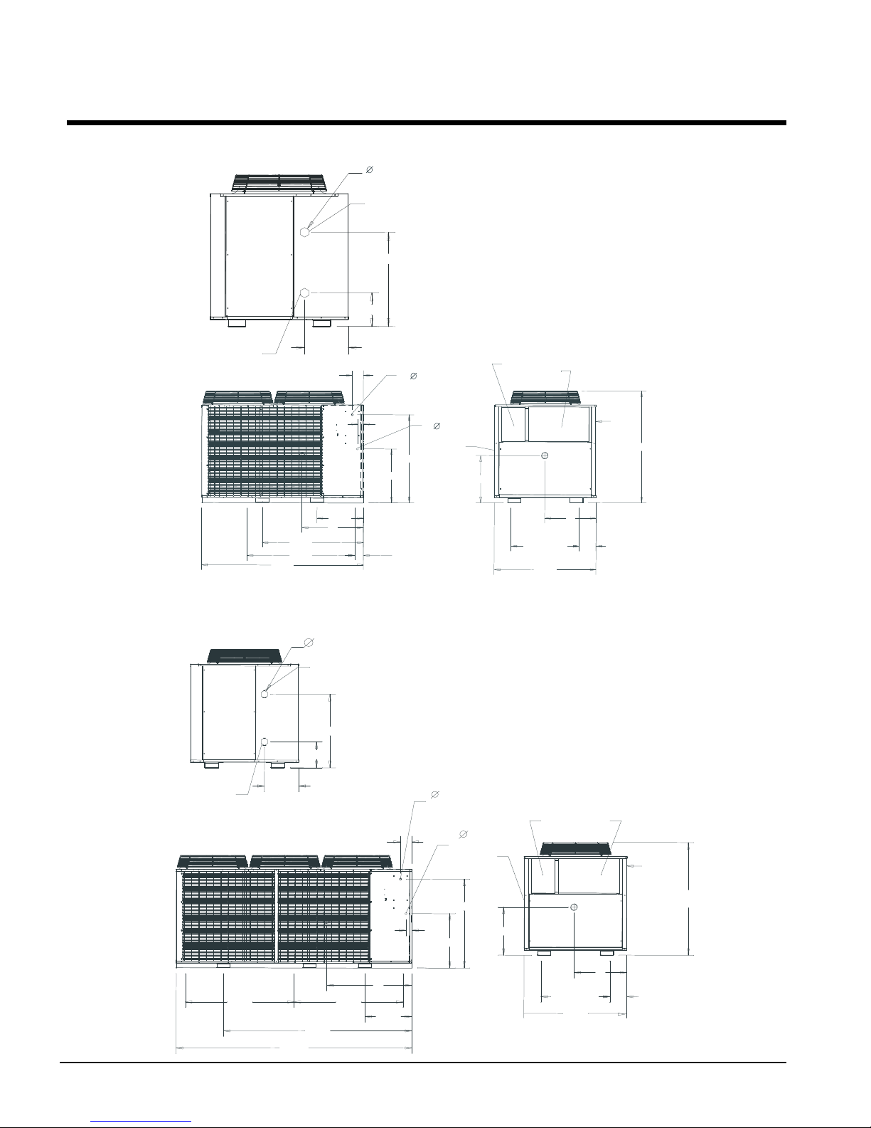
Dimensions & Weights
CERTIFIED, 2 FAN, AGZ-B
QTY. 4
3.00
R331987101
AGZ029-034 = 59
3.00
Figure 8, AGZ 010BS - 017BS, Packaged (See page 30 for additional dimensions and weights)
ACCESS
PANEL
QTY.2
EVAP.
INLET
31.70
EVAP.
OUTLET
14.66
73.80
46.18
49.06
5.17
L1, L2L3, L4
21.18
X
11.27
2.61
.875
POWER ENTRY
KNOCKOUT
(OTHER SIDE)
CONTROL
ELECTRICAL
KNOCKOUT
40.18
24.57
4.00
MOUNTING HOLES
DIA. 1.00 INCH
.875
ACCESS DOORS
Y
CONTROL BOX
31.15
MOUNTING
HOLES
46.42
ACCESS
DOOR
Z
7.64
POWER
ENTRY
R331987001
51.00
00
Figure 9, AGZ 020BS - 034BS,packeged (See page 30 for additional dimensions and weights)
QTY.2
EVAP.
ACCESS
PANEL
EVAP.
OUTLET
14.66
49.06 49.06
106.23
INLET
11.27
84.95
31.70
DIM. A = AGZ020-025 = 24.6"
AGZ029-034 = 33.0"
DIM. B = AGZ020-025 = 40.2"
AGZ029-034 = 48.7"
.875
POWER ENTRY
KNOCKOUT
(OTHER SIDE)
5.17
2.67
A
L1, L2L3, L4
X
21.18
.875
CONTROL
ELECTRICAL
KNOCKOUT
B
Y
NOTE:
L2 & L4 ARE LOCATED ON1.
OPPOSITE SIDE OF UNIT.
ALL WEIGHTS ARE IN POUNDS.2.
CONTROL PANEL
ACCESS DOORS
ACCESS
DOOR
Z
31.10
MOUNTING
HOLES
46.38
7.64
CERTIFIED, 3 FAN, AGZ-B
POWER
ENTRY
AGZ020-025 =51
28 AGZ 010B through 034B IOMM AGZB1
Page 29

Figure 10, AGZ 010 - 017BM Remote Evap. (See page 30 for additional dimensions and weights
00
CERTIFIED, 2 FAN, AGZ-B REMOTE
DIM. A = ACZ025-028 = 24.6"
NOTE:
ACZ033-039 = 59
ACCESS
PANEL
NOTE:
L2 & L4 ARE LOCATED ON1.
OPPOSITE SIDE OF UNIT.
ALL WEIGHTS ARE IN POUNDS.2.
5.17
HOT GAS
BYPASS
L1, L2L3, L4
73.80
21.18
X
46.18
49.06
18.84
9.19
4.56
5.06
8.86
.875
POWER ENTRY
KNOCKOUT
(OTHER SIDE)
CONTROL
ELECTRICAL
20.79
KNOCKOUT
24.57
SUCTION
LIQUID
4.00
MOUNTING HOLES
DIA. 1.00 INCH
.875
CONTROL BOX
ACCESS DOORS
ACCESS
DOOR
R331987401
31.15
MOUNTING
HOLES
46.42
POWER
ENTRY
51.00
Y
Z
7.64
Figure 11, AGZ 020BM - 034BM (See page 30 for additional dimensions and weights
ACCESS
PANEL
DIM. B = ACZ025-028 = 40.2"
DIM. C = ACZ025-033 = 18.8"
DIM. D = ACZ025-033 = 4.5"
ACZ033-039 = 33.0"
ACZ033-039 = 48.7"
ACZ039 = 12.6"
ACZ039 = 7.5"
L2 & L4 ARE LOCATED ON1.
OPPOSITE SIDE OF UNIT.
ALL WEIGHTS ARE IN POUNDS.2.
49.06 49.06
106.23
.875
POWER ENTRY
KNOCKOUT
(OTHER SIDE)
84.95
5.17
HOT GAS BYPASS
.875
CONTROL
ELECTRICAL
KNOCKOUT
D
2.67
SUCTION
C
9.19
L1,L2L3,L4
21.18
X
LIQUID
5.06
8.86
20.79
B
A
R331987501 CERTIFIED, 3 FAN, AGZ-B REMOTE
CONTROL PANEL
ACCESS DOORS
ACCESS
DOOR
31.10
MOUNTING
HOLES
46.38
POWER
ENTRY
ACZ025-028 =51
Y
Z
7.64
IOMM AGZB1 AGZ 010B through 034B 29
Page 30

Remote Evaporators
3.5
(90)
1.2
(30)
Inlet
Outlet
Suction
Temp Sensor
Figure 12, Remote Evaporators, for AGZ 010BM – 034BM
30.2
(767)
Liquid
.35
(9)
8.2 (208)
10.2 (260)
1.2
(30)
3.5
(90)
A
W1
W2
AGZ
Model
010
013
017
020
025
029
034
Liquid Line Conn.
Brazed, in (L).
1.125 2.125 0.75 2.0 3.6 (91)
1.125 2.125 0.75 2.0 6.0 (153)
1.125 2.125 0.75 2.0 7.1 (181)
1.125 2.125 0.75 2.0 7.7 (195)
1.125 2.125 0.75 2.0 10.6 (271)
1.375 2.125 0.75 2.0 13,8 (351)
1.375 2.125 0.75 2.0 19.0 (483)
Suction Line Conn.
Brazed, in (S).
Temp. Sensor
NPT, in. (TS)
Victaulic
Water Conn.
In. (W)
Dimension
“A”
in. (mm)
30 AGZ 010B through 034B IOMM AGZB1
Page 31

ACZ/AGZ Dimensions and Weights
010B
(IN.)
(LBS)
BYPASS
010B
MOUNTING CORNER WEIGHTS (LBS.)
EVAP
010B
Table 14, Packaged Chiller, Dimensions and Weights
AGZ
UNIT
SIZE
013B
017B
020B
025B
029B
034B
CENTER OF GRAVITY
(IN.)
X Y Z
28.00 21.50 23.40 1085 1095 398 392 149 147 2 279 275 267 263
27.40 21.40 23.90 1170 1190 452 426 150 141 2 315 297 288 271
27.50 21.60 24.00 1280 1300 493 463 167 157 2 344 323 316 297
38.50 21.80 23.90 1505 1525 564 534 209 198 2 502 475 271 257
39.50 19.40 24.00 1610 1635 593 554 239 224 2 531 496 301 282
41.00 22.75 24.20 1800 1830 645 595 291 269 2 583 238 353 326
35.60 23.70 23.50 2270 2315 890 869 259 253 2 779 761 369 361
SHIP WT.
(LBS)
OPN. WT.
(LBS)
Table 15, Remote Evaporator, Dimensions and Weights
AGZ
REMOTE
EVAP.
013B
017B
020B
025B
029B
034B
CENTER OF GRAVITY
X Y Z
27.50 21.70 22.90 1000 1015 369 379 124 128 1.125 0.875 0.625
26.50 21.60 23.40 1065 1090 421 416 115 113 1.625 0.875 0.625
26.60 21.80 23.30 1150 1190 454 449 124 123 1.625 0.875 0.625
38.50 21.90 23.30 1370 1420 501 498 186 185 1.625 0.875 0.625
38.50 19.10 23.30 1390 1445 508 505 189 188 1.625 0.875 0.625
41.00 23.00 23.30 1565 1625 540 538 244 243 1.625 0.875 0.875
34.60 24.00 22.40 1975 2050 753 807 201 215 2.125 0.875 0.875
SHIP
WT.
(LBS)
OPN.
(LBS)
LIFTING CORNER WEIGHTS
WT.
LIFTING CORNER
WEIGHTS (LBS)
L1 L2 L3 L4
L1 L2 L3 L4 SUCTION LIQUID
EVAP.
CONN.
(IN.)
VICTAULIC
CONNECTION SIZES (IN. O.D.)
MOUNTING CORNER
WEIGHTS (LBS.)
M1 M2 M3 M4
HOT GAS
Table 16, Mounting Weights
AGZ
REMOTE
013B
017B
020B
025B
029B
034B
M1 M2 M3 M4
257 264 236 243
290 286 246 243
312 309 266 263
446 443 241 240
453 449 245 243
488 487 296 295
656 703 297 318
IOMM AGZB1 AGZ 010B through 034B 31
Page 32

System Maintenance
General
On initial start-up and periodically during operation, it will be necessary to perform certain
routine service checks. Among these are taking electric leg readings. Some readings are
readily available on the MicroTech II controller’s display.
Lubrication
No routine lubrication is required on the AGZ units. The fan motor bearings are of the
permanently lubricated type and require no lubrication.
Electrical Terminals
Electric shock hazard. Disconnect and tag out all sources of power to the unit before
continuing with following service or severe personal injury or death can result.
Normal heating and cooling of the wire will cause terminals to loosen. Retighten all power
electrical terminals every six months.
Condensers
Condensers are air-cooled and constructed with 3/8” (9.5mm) O.D. internally finned copper
tubes bonded in a staggered pattern into slit aluminum fins. No maintenance is ordinarily
required except the occasional removal of dirt and debris from the outside surface of the
fins. Use locally purchased foaming condenser coil cleaners for periodic cleaning of the
coil. Condenser cleaners may contain harmful chemicals, be careful when using cleaners.
Care should be taken not to damage the fins during cleaning. All chemical cleaners should
be thoroughly rinsed from the coils.
!
WARNING
Refrigerant Sight glass
Observe the refrigerant sight glass monthly. A clear glass of liquid indicates adequate subcooled refrigerant charge in the system to ensure proper feed through the expansion valve.
Bubbling refrigerant in the sight glass indicates the system is short of refrigerant charge.
Sub-cooling should be verified to prevent overcharging. Refrigerant gas flashing in the
sight glass could also indicate an excessive pressure drop in the line, possibly due to a
clogged filter-drier or a restriction elsewhere in the system. The sight glass indicates what
moisture condition corresponds to a given element color. If the sight glass does not indicate
a dry condition after about 12 hours of operation, the refrigerant or oil should be tested for
moisture.
32 AGZ 010B through 034B IOMM AGZB1
Page 33

Standard MicroTech II Controller
Table of Contents
Overview .............................................................................34
General Description ............................................................. 34
Compressor Motor Description .......................................34
FanTrol Head Pressure Control .......................................34
Inputs/Outputs ................................................................ 35
Setpoints ........................................................................35
Equipment Protection Alarms ......................................... 37
Control Functions and Definitions ..................................39
Limit Alarms ..................................................................39
Control Functions ...........................................................39
Unit Enable ....................................................................41
Unit Mode Selection .......................................................41
Unit State ....................................................................... 42
Evaporator Pump state ....................................................43
Condenser Fans ..............................................................44
Compressor Control........................................................ 45
Using the Controller............................................................. 39
Display and Keyboard ..................................................... 48
Getting Started .....................................................................48
Menu Screens ................................................................. 49
Menu Matrix...................................................................51
View Screens Defined ..................................................... 52
Alarm Screens Defined ...................................................54
Set Screens Defined........................................................55
Software Version AGZSU0102D
IOMM AGZB1 AGZ 010B through 034B 33
Page 34
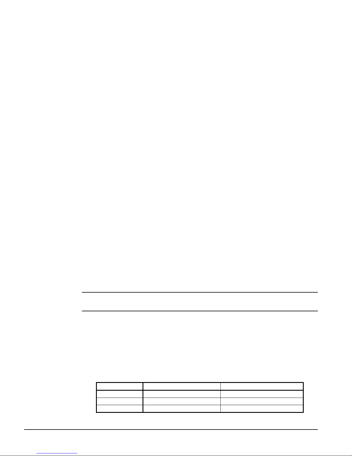
Overview
The MicroTech II controller’s state-of-the-art design will not only permit the chiller to run
more efficiently, but will also simplify troubleshooting if a system failure occurs. Every
MicroTech II controller is programmed and tested prior to shipment to contribute to a
trouble-free start-up.
Release Version
This manual covers Software Release AGZ SU0102D
Operator-friendly
The MicroTech II controller’s menu structure is separated into three distinct categories,
which provide the operator or service technician with a full description of current unit
status, control parameters, and alarms. Security protection prevents unauthorized changing
of the setpoints and control parameters.
The MicroTech II controller continuously performs self-diagnostic checks, monitoring
system temperatures, pressures and protection devices, and will automatically shut down a
compressor or the entire unit should a fault occur. The cause of the shutdown will be
retained in memory and can be easily displayed in plain English for operator review. The
MicroTech II chiller controller will also retain and display the time the fault occurred. In
addition to displaying alarm diagnostics, the MicroTech II chiller controller also provides
the operator with a warning of limit (pre-alarm) conditions.
Staging
The two scroll compressors are staged on and off as a function of leaving chilled water
temperature. Lead/lag is automatic and switched every ten starts.
General Description
Compressor Motor Protection
The solid-state compressor motor protector module incorporates a 2-minute “time-off”
relay utilizing the bleed-down capacitor principle. Any time the protection system opens or
power to the module is interrupted, the 2-minute “time-off” delay is triggered and the
module will not reset for two minutes. Once the 2-minute period has passed the motor
protector contacts M1 and M2 reset, provided the protection system is satisfied and power
is applied to the module.
Note: If the power circuit is broken once the 2-minute period is passed, the pilot
circuit will reset without delay when power is reapplied.
AGZ 010: The model AGZ 010 compressor has internal line breakage with automatic reset.
FanTrol Head Pressure Control
FanTrol is the standard method of head pressure control that automatically cycles the
condenser fan motors in response to condenser pressure. This function is controlled by the
microprocessor, maintains head pressure and allows the unit to run at low ambient air
temperatures down to 35°F (1.7°C). Fans are staged as follows:
Table 17, Fan Staging Pressures
Fan Two-Fan Unit Three-Fan Unit
Stage #1 On 150 psig, Off with unit On 150 psig, Off with unit
Stage #2 On 290 psig, Off 170 psig On 290 psig, Off 170 psig
Stage #3 -- On 310 psig, Off 180 psig
Note: Fan #1 is on with first compressor above 75°F (24°C).
34 AGZ 010B through 034B IOMM AGZB1
Page 35

Inputs/Outputs
Table 18, Inputs and Outputs
Analog Inputs
# Description Signal Source Range
1 Reset of Leaving Water Temperature 4-20 mA Current
2 Evaporator Refrigerant Pressure 0.5 to 4.5 VDC (NOTE 1)
3 Condenser Refrigerant Pressure 0.5 to 4.5 VDC (NOTE 1)
4 Leaving Evaporator Water Temperature
5 Outside Ambient Temperature
Thermister (10k at 77°F, 25°C)
Thermister (10k at 77°F, 25°C)
NOTE 1: Value at the converter board input. Value at the converter board output is 0.1 VDC – 0.9 VDC.
Analog Outputs
# Description Output Signal Range
1-4 None -- --
Digital Inputs
# Description Signal Signal
1 Unit OFF Switch 0 VAC (Stop) 24 VAC (Auto)
2 Remote Start/Stop 0 VAC (Stop) 24 VAC (Start)
3 Evaporator Water Flow Switch 0 VAC (No Flow) 24 VAC (Flow)
4 Motor Protection 0 VAC (Fault) 24 VAC (No Fault)
5 Ice Mode Switch 0 VAC (Normal) 24 VAC (Ice)
6 Phase Voltage Fault 0 VAC (Fault) 24 VAC (No Fault)
7 Open -- -8 Open -- --
0 to10 degrees
60°F max inlet
0 to 132 psi
3.6 to 410 psi
-58 to 212°F
-58 to 212°F
Digital Outputs
# Description Load Output OFF Output ON
1 Alarm Alarm Indicator Alarm OFF Alarm ON
2 Evaporator Water Pump Pump Contactor Pump OFF Pump ON
3 Liquid Line Solenoid Cooling OFF Cooling ON
4 Motor Control Relay #1 Starter Compressor OFF Compressor ON
5 Motor Control Relay #2 Starter Compressor OFF Compressor ON
6 Condenser Fan #1 Fan Contactor Fan OFF Fan ON
7 Condenser Fan #2 Fan Contactor Fan OFF Fan ON
8 Condenser Fan #3 Fan Contactor Fan OFF Fan ON
Setpoints
The setpoints shown in Table 19 are battery-backed and remembered during power off, are
factory set to the Default value, and can be adjusted within the value shown in the Range
column.
The PW (password) column indicates the password level that must be entered in order to
change the setpoint. Passwords are as follows:
O = Operator [0100]
M = Manager, [2001] M level settings are not normally changed for chilled water airconditioning applications.
IOMM AGZB1 AGZ 010B through 034B 35
Page 36

Table 19, Setpoints
Description Default Range PW
Unit
Unit Enable OFF OFF, ON O
Unit Mode COOL
Control Source SWITCHES
Available Modes COOL
Display Units
Language ENGLISH ENGLISH, O
Cool LWT
Ice LWT
Evap Delta T
Startup Delta T
Stop Delta T 0.5F 0 to 3.0F O
Max Pulldown Rate 1.0F
* Refrigerant Type (Note 1) None R22, R407c -BAS Protocol Modbus BACnet, LONW
Ident Number 001 001 to 999 M
Baud rate 9600 1200,2400,4800,9600,19200 M
* SpeedTrol Option N N,Y M
Password 0000 0000 to 9999 --
Staging
Stage Up Delay 120 20 to 240 sec M
Stage Down Delay 30 10 to 60 sec M
Timers
Evap Flow Proof 3 sec 1 to 10 sec M
Evap Recirculate Timer 30 sec 15 to 300 sec. M
Low Evap Pressure Delay 30 sec 15 sec to 30sec M
Ice Time Delay 12 hrs. 1 to 23 hrs M
Clear Ice Delay NO No, Yes M
Start-Start 15 min 10 to 60 min M
Stop-Start 5 min 3 to 20 min M
Stage Up Delay 240 sec. 20 to 480 sec. M
Stage Down Delay 30 sec. 10 to 60 sec. M
Comp 1 Enable On Off, On
Comp 2 Enable On Off, On
Alarms
Evaporator Freeze
Low Evap Pressure 58 psi 30 to 60 psi M
Low Evap Pressure-Hold 59 psi 31 to 65 psi M
Low Evap Pressure-Unload 59 psi 31 to 65 psi M
High Condenser Stage Down 370 psi 365 to 375 psi M
High Condenser Pressure 380 psi 380 to 390 psi M
* Phase Voltage Protection N N,Y M
* Low Ambient Lockout
Condenser Fans
Fan Stages 2 2-3
Speedtrol Option No No,Yes
Stage #1 On (OAT<75°F)
Stage #2 On 290 psi 230 to 330 psi M
Stage #3 On 300 psi 230 to 330 psi M
Stage #1 Off 140 psi 130 to 170 M
Continued next page.
COOL
COOL w/Glycol
ICE w/Glycol
TEST
SWITCHES, KEYPAD,
NETWORK
COOL
COOL w/GLYCOL
COOL/ICE w/GLYCOL
TEST
°F/psi °F/psi
44. 0°F 20.0 to 60.0 °F
40. 0°F 20.0 to 40.0 °F
10. 0°F 6.0 to 16.0 °F
10.0°F 1.0 to 15.0 °F
0.5 to 5.0°F
ORKS
, Modbus M
36.0 °F 18 to 42 °F
35.0 °F –2 to 60 °F
200psi 140 to 200 psi M
O
O
M
O
O
O
O
O
M
M
M
36 AGZ 010B through 034B IOMM AGZB1
Page 37

Description Default Range PW
Stage #2 Off 180 psi 150 to 200 psi M
Stage #3 Off 190 psi 150 to 200 psi M
Sensor Offsets
Evaporator Refrig Press Sensor Offset 00.0 psi -20.0 to 20.0 psi
Condenser Refrig Press Sensor Offset 00.0 psi -20.0 to 20.0 psi
Leaving Evaporator Water Temp Sensor
Outside Ambient Temperature Sensor
NOTES:
1. This setting is a one-time only setting and is mad in the factory.
2. (*) These items are factory set prior to shipment.
0.0 °F -5.0 to 5.0 °F
0.0 °F -5.0 to 5.0 °F
Automatic Adjusted Ranges
The following are setpoints that will be limited based on the option(s) selected.
Evaporator Leaving Water Temperature
Mode Range
Unit Mode = Cool
Unit Mode = Cool w/Glycol
Evaporator Freeze Temperature
Mode Range
Unit Mode = Cool
Unit Mode = Cool w/Glycol, Ice
w/Glycol
40 to 60°F
20 to 60°F
36 to 42°F
18 to 42°F
Low Ambient Lockout Temperature
SpeedTrol Range
SpeedTrol = N
SpeedTrol = Y
35 – 60°F
-2 – 60°F
Low Evaporator Pressure Hold and Unload
Mode Refrigerant Range
Unit Mode = Cool R22 55 to 65 Psig
Unit Mode = Cool w/Glycol, Ice w/Glycol R22 24 to 65 Psig
Unit Mode = Cool R407c 58 to 65 Psig
Unit Mode = Cool w/Glycol, Ice w/Glycol R407c 20 to 65 Psig
Dynamic Default Values
Some setpoints will have different default values loaded depending on the value of other
setpoints.
Low Evaporator Pressure Hold
Refrigerant Default Value
R22 59 psi
R407C 60 psi
Low Evaporator Pressure Unload
Refrigerant Default Value
R22 58 psi
R407C 59 psi
IOMM AGZB1 AGZ 010B through 034B 37
Page 38

Setpoint Security
All setpoints are protected by using passwords. Two four-digit passwords provide
OPERATOR and/or MANAGER levels of access to changeable parameters. Once a
password has been entered, it remains valid for 15 minutes after the last key-press on the
unit controller.
After a valid password has been entered, setpoints may be changed. If the operator
attempts to edit a setpoint on a controller while the correct password is not active, no action
will be taken.
Passwords can be entered using the ENTER PASSWORD screen which is the last screen in
the SET UNIT SPs column.
The password is entered by pressing the ENTER key, scrolling to the correct value with the
UP and DOWN arrow keys, and pressing ENTER again. The entered password is not
shown after the enter key is pressed. Once the correct password has been entered, the
PASSWORD screen indicates which password is active (operator or manager). If the
wrong password is entered, there is no level of access so the active password displays
“none”. Entering an incorrect password while a password is active will render that
password inactive.
Equipment Protection Alarms
Equipment protection alarms execute rapid compressor shutdown (no pumpdown cycle),
triggers the alarm output, lights the red alarm light on the controller left arrow button and
registers it in the alarm log.
The following table identifies each equipment protection alarm, gives the condition that
causes the alarm to occur, and states the action taken because of the alarm. Otherwise, the
alarm is manually reset, requiring the operator to clear the alarm.
Table 20, Shutdown Alarms
Description Occurs When:
No Evaporator Water Flow
(See NOTE)
Low Evaporator Pressure
High Condenser Pressure
Mechanical High Pressure MHP input is low Rapid Stop Manual
Motor Protection
Phase Voltage Protection
(opt)
Low Ambient Restart Fault
Evaporator Freeze Protect Evap LWT < Evaporator Freeze SP Rapid Stop Manual
Leaving Evaporator Water
Temperature Sensor Fault
Evaporator Pressure Sensor
Fault
Condenser Pressure Sensor
Fault
Outside Ambient
Temperature Sensor Fault
Evap Pump State = RUN and Flow Switch
Digital Input = No Flow and time greater than
Evap Flow Proof SP
Evaporator Press < Low Evap Pressure SP start
Low Evap Pressure Time Delay – if after Time
Delay if Evap Press > SP continue else stop
Condenser Press > High Condenser Pressure
SP
Digital Input = High Motor Temperature
On Power Up – Delay 150 Sec. before checking
If Phase Voltage Protection = Y, Then Digital
Input = Phase/Voltage Problem
Failed three consecutive low ambient start
attempts
Sensor shorted or open Rapid Stop Manual
Sensor shorted or open Rapid Stop Manual
Sensor shorted or open Rapid Stop Manual
Sensor is open or shorted Rapid Stop Manual
NOTE: Beginning with this software version, two automatic resets per day (beginning at 12:00 am)
are allowed on the flow loss alarm. The Unit State remains on Auto and the evaporator will go back
to Start, waiting for flow.
Action
Taken
Rapid Stop Auto/Manual
Rapid Stop Manual
Rapid Stop Manual
Rapid Stop Manual
Rapid Stop
Rapid Stop Manual
Reset
Phase/Voltage
Input Returns
to Normal
38 AGZ 010B through 034B IOMM AGZB1
Page 39

Events (Limit Alarms)
The following events limit the operation of the chiller in some way as described in the
Action Taken column. These alarms are auto-clearing based on reaching the conditions in
the reset column.
Table 21, Events (Limit Alarms)
Description Occurs When: Action Taken Reset
Condenser Pressure
High Unload
Failed Pumpdown
Low Evaporator
Pressure – Hold
Low Evaporator
Pressure – Unload
NOTE: SP = Setpoint
Pressure > High Condenser Stage
Down setpoint
Unit is pumping down for over 60
seconds
Pressure < Low Evap Pressure–Hold
setpoint
Pressure < Low Evap Pressure–
Unload setpoint
Control Functions and Definitions
Control Band
Control Band = Evap delta setpoint * 0.6
Upper and Lower Control Band
The control band is normally centered around the active LWT setpoint. If the chiller is not
set up to use glycol, then the control band will be shifted up relative to the LWT setpoint to
keep the lower end of the control band at least at 39°F. If the band doesn’t need to be
shifted to achieve this, it will remain centered on the active LWT setpoint.
Shutoff Stage #2
Shut down unit N/A
Hold @
Stage 1
Shutoff
Stage 2
Condenser Press drops
below (SP – 100psi)
Evap Press rises above
(SP + 8psi)
Evap Press rises above
(SP + 10 psi)
In the staging logic, an upper and lower control band are used. The lower control band is
calculated as follows:
IF Active LWT Setpoint – 39 < 0.5 * Control Band THEN
Lower Control Band = Active LWT Setpoint – 39
ELSE Lower Control Band = 0.5 * Control Band
The upper control band is then Control Band – Lower Control Band
Leaving Water Reset
The leaving water reset input uses a 4-20mA signal to reset the leaving water setpoint to a
higher value. The adjustment varies linearly from 0 to 10°F, with a reset of 0 for a 4mA
signal and a reset of 10 for a 20mA signal.
Active LWT Setpoint
The active LWT setpoint represents the current control setpoint based on unit mode and
reset. If unit mode is ice, then the active setpoint is equal to the ice setpoint. If the unit
mode is cool, the active setpoint is the cool setpoint plus the leaving water reset value.
LWT Error
LWT error compares the actual LWT to the active LWT setpoint. The equation is:
LWT error = LWT – active LWT setpoint
LWT Slope
LWT slope is calculated such that the slope represents a time frame of one minute.
IOMM AGZB1 AGZ 010B through 034B 39
Page 40

Every 12 seconds, the current LWT is subtracted from the value 12 seconds back. This
value is added to a buffer containing values calculated at the last five intervals. The final
result is a slope value that is an average over the past 60 seconds.
Pulldown Rate
The slope value calculated above will be a negative value as the water temperature is
dropping. For use in some control functions, the negative slope is converted to a positive
value by multiplying by –1.
Refrigerant Saturated Temperature
Methods for calculating saturated refrigerant temperature differ with each refrigerant.
R22 Saturated Temperature
Evaporator saturated temperature and condenser saturated temperature are calculated from
the pressures for each circuit. The pressure will be fitted to a curve made up of 13 straight
line segments. The points used to define these segments are as follows.
Pressure (PSI) Temperature (oF)
24.0 0
34.7 12.0
47.6 24.0
62.8 36.0
80.8 48.0
101.6 60.0
126.2 72.0
153.8 84.0
185.2 96.0
220.6 108.0
260.5 120.0
305.2 132.0
355.1 144.0
430.4 160.0
R407C Saturated Temperature
Evaporator dew point and condenser midpoint are calculated using 32-bit math. The
equation is as follows:
If Pressure < 120 psi Then
Saturation = [Pressure x 145/105] – [(Pressure2)/2000] – 250
If Pressure >= 120 psi Then
Saturation = [Pressure x 46/94] – [Pressure2/25000] + 145
Evaporator Approach
The evaporator approach is calculated for each circuit. The equation is as follows:
Evaporator Approach = LWT – Evaporator Saturated Temperature
Suction Superheat
Suction superheat is calculated for each circuit using the following equation:
Suction superheat = Suction Temperature – Evaporator Saturated Temperature
40 AGZ 010B through 034B IOMM AGZB1
Page 41
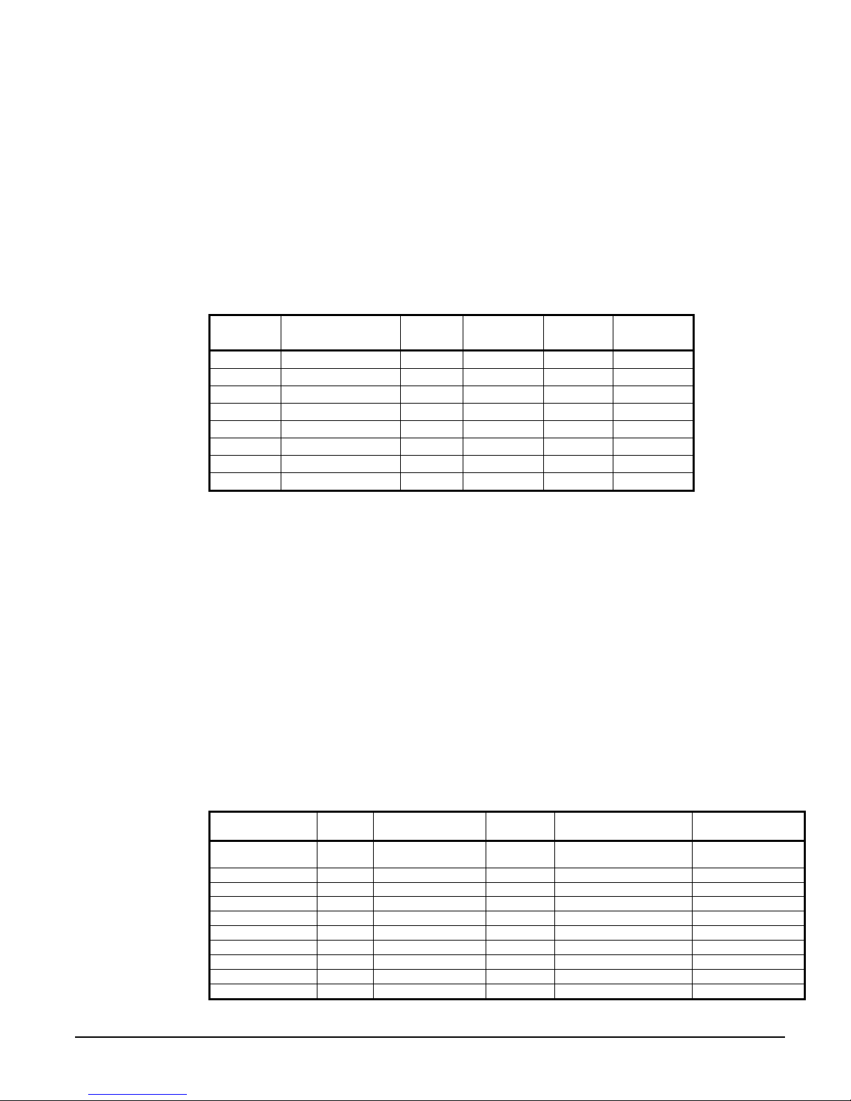
Pumpdown Pressure
The pressure to which a circuit will pumpdown is based on the Low Evaporator Pressure
Unload setpoint. The equation is as follows:
Pumpdown pressure = Low evap pressure unload – 15 psi , with the calculated value
limited to a minimum of 10 psi.
Unit Enable
Enabling and disabling the chiller is controlled by the Unit Enable Setpoint with options of
OFF and ON. This setpoint can be altered by the Unit OFF input, Remote input, keypad
entry, and BAS request. The Control Source Setpoint determines which sources can change
the Unit Enable Setpoint with options of SWITCHES, KEYPAD or NETWORK.
Changing the Unit Enable Setpoint can be accomplished according to the following table.
NOTE: An “x” indicates that the value is ignored.
Unit Off
Input
OFF x x x x OFF
x SWITCHES OFF x x OFF
ON SWITCHES ON x x ON
ON KEYPAD x OFF x OFF
ON KEYPAD x ON x ON
ON NETWORK x x OFF OFF
ON NETWORK OFF x x OFF
ON NETWORK ON x ON ON
Unit Mode
The overall operating mode of the chiller is set by the Unit Mode Setpoint with options of
COOL, COOL w/Glycol, ICE w/Glycol, and TEST. This setpoint can be altered by the
keypad, BAS, and Mode input. Changes to the Unit Mode Setpoint are controlled by two
additional setpoints.
• Available Modes Setpoint: Determines the operational modes available at any time
with options of COOL, COOL w/Glycol, COOL/ICE w/Glycol, ICE w/Glycol and
TEST.
• Control Source Setpoint: Determines the source that can change the Unit Mode
Setpoint with options of KEYPAD, NETWORK, or SWITCHES.
When the Control source is set to KEYPAD, the Unit Mode stays at its previous setting
until changed by the operator. When the Control source is set to BAS, the most recent BAS
mode request goes into effect even if it changed while the Control source was set to
KEYPAD or DIGITAL INPUTS.
Changing the Unit Mode Setpoint can be accomplished according to the following table.
NOTE: An “x” indicates that the value is ignored.
Control Source
Setpoint
Remote
Input
Key-
Pad Entry
BAS
Request
Unit
Enable
Control Source
Setpoint
x x x x
x x x x COOL w/Glycol COOL w/Glycol
SWITCHES OFF x x COOL/ICE w/Glycol COOL w/Glycol
SWITCHES ON x x COOL/ICE w/Glycol ICE w/Glycol
KEYPAD x COOL w/Glycol x COOL/ICE w/Glycol COOL w/Glycol
KEYPAD x ICE w/Glycol x COOL/ICE w/Glycol ICE w/Glycol
NETWORK x x COOL COOL/ICE w/Glycol COOL w/Glycol
NETWORK x x ICE COOL/ICE w/Glycol ICE w/Glycol
x x x x ICE w/Glycol ICE w/Glycol
x x x x TEST TEST
IOMM AGZB1 AGZ 010B through 034B 41
Mode
Input
Keypad Entry
BAS
Request
Available Modes
Setpoint
COOL
Unit Mode
COOL
Page 42

Unit Test Mode
The unit test mode allows manual testing of controller outputs. Entering this mode requires
the following conditions.
• Unit Switch = OFF
• Manager password active.
• Available Unit Mode setpoint = TEST
A test menu can then be selected to allow activation of the outputs. It is possible to switch
each digital output ON or OFF and set the analog outputs to any value.
Power Up Start Delay
After powering up the unit, the motor protectors may seem to not work properly for up to
150 seconds. After the control is powered up, no compressor can start for 150 seconds. In
addition, the motor protect inputs are ignored during this time so as to avoid tripping a false
alarm.
Ice Mode Start Delay
An adjustable start to start ice delay timer will limit the frequency with which the chiller
may start in Ice mode. The timer starts when the first compressor starts while the unit is in
ice mode. While this timer is active, the chiller cannot restart in Ice mode. The time delay
is user adjustable.
The ice delay timer may be manually cleared to force a restart in ice mode. A setpoint
specifically for clearing the ice mode delay is available. In addition, cycling the power to
the controller will clear the ice delay timer.
Unit State
The Unit shall always be in one of three states. These states are Off, Auto, and Pumpdown.
Transitions between these states are shown in the following diagram (Figure 13, Unit State
Diagram).
T1: Off to Auto
All of the following must be true:
• Unit Enabled
• No Alarm
• IF Unit Mode = Ice THEN [Ice Timer Expired]
T2: Auto to Pumpdown
Any of the following must be true:
• Keypad Enable = Off
• BAS Enable = Off
• Remote Switch = Off
• Pumpdown Alarm Active
T3: Pumpdown to Off
Any of the following must be true:
• Unit Alarm
• Unit Switch Off
• No Compressors Running
T4: Auto to Off
Any of the following must be true:
• Unit Alarm
• Unit Switch Off
• No Compressors Running AND [Unit Mode = Ice AND Ice Delay Active]
42 AGZ 010B through 034B IOMM AGZB1
Page 43

Figure 13, Unit State Diagram
Unit State Diagram
Power On
T3
Pumpdown Auto
Off
T2
Evaporator Water Pump State Control
Operation of the evaporator pump is controlled by the state-transition diagram shown
below.
T4
T1
Figure 14, Evaporator Pump State
Evaporator Pump
Power ON
T3
RUN
See transition code on following page.
States
T5
OFF
T1
T4
T2
START
IOMM AGZB1 AGZ 010B through 034B 43
Page 44

Transitions:
T1 – Transition from Off to Start
Requires any of the following
• Unit state = Auto
• LWT < Freeze setpoint - 1
T2 – Transition from Start to Run
• Flow ok for time > evaporator recirculate time
T3 – Transition from Run to Off
• Unit state = Off AND LWT > Freeze setpoint
T4 – Transition from Start to Off
• Unit state = Off AND LWT > Freeze setpoint
T5 – Transition from Run to Start
Requires all of the following
• Evaporator water flow loss for time > evaporator flow proof setpoint
Condenser Fans
Condenser fans are staged up and down based on the fan stage setpoint. These setpoints
define pressures at which fans will start or stop.
Fan 1 will start with the first compressor when the ambient temperature is greater than
75°F. Below 75°F, this fan starts when the condenser pressure gets up to the Stage #1 On
setpoint. Fan 2 will start when the condenser pressure gets up to the Stage #2 On setpoint,
and fan 3 will start when the condenser pressure gets up to the Stage #3 On setpoint.
Fan 3 will stop when the condenser pressure drops to the Stage #3 Off setpoint, and Fan 2
will stop when the condenser pressure drops to the Stage #2 Off setpoint. Fan 1 will stop
when the pressure drops down to the Stage #1 Off setpoint.
Low OAT Start
In order to avoid low pressure alarms at startup, low OAT start logic allows for running at
low pressures for a longer time than normal as well as multiple start attempts.
A low OAT start is initiated if the condenser saturated temperature is less than 85°F when
the compressor starts. Once this happens, the circuit is in this low OAT start state for a
time equal to the low OAT start timer setpoint. During this time, the freezestat logic and
the low pressure events are disabled. The absolute limit of 5 psi is still enforced.
At the end of the low OAT start, the evaporator pressure is checked. If the pressure is
greater than, or equal to, the low evaporator pressure unload setpoint, the start is considered
successful. If the pressure is less than the unload setpoint, the start is not successful and
the compressor will stop. Three start attempts are allowed before tripping on the restart
alarm. So if on the third attempt, the start is not successful, the restart alarm is triggered.
The restart counter is be reset when either a start is successful or the circuit is off on an
alarm.
Circuit Capacity Overrides
The following conditions override the automatic capacity control when the chiller is in
Cool Mode only. These overrides keep the unit from entering a condition in which it is not
designed to run.
Low Evaporator Pressure
If the evaporator pressure drops below the Low Evaporator Pressure Hold setpoint, the Low
Evaporator Pressure Inhibit event is triggered. This can occur with either one or two
compressors running. When triggered, the second compressor will not be allowed to start if
only one is currently running. If both compressors are already running, no action is taken.
44 AGZ 010B through 034B IOMM AGZB1
Page 45

If the evaporator pressure drops below the Low Evaporator Pressure Unload setpoint, the
Low Evaporator Pressure Unload event is triggered. This can only occur when both
compressors are running. When triggered, one compressor is shut off.
These events are logged to an event log when they occur. Both remain active until the
evaporator pressure rises 5 psi above the hold setpoint or both compressors are off.
High Condenser Pressure
If the discharge pressure rises above the High Condenser Pressure Unload setpoint and both
compressors are running, the High Condenser Pressure Unload event is triggered. One
compressor will be shut off when this occurs.
This event will also be logged to an event log when it occurs. It will remain active until the
condenser pressure drops 100 psi below the unload setpoint. While active, the second
compressor cannot turn back on.
Maximum LWT Rate
The maximum rate at which the leaving water temperature can drop is limited by the
Maximum Pulldown Rate setpoint when the unit mode is Cool. If the rate exceeds this
setpoint, no more compressors can be started until the Pulldown Rate is less than the
setpoint. Running compressors will not be stopped as a result of exceeding the maximum
pulldown rate.
Low Ambient Lockout
If the OAT drops below the low ambient lockout setpoint, then the unit will do a normal
stop. Once the lockout has been triggered, no compressors will start until the OAT rises to
the lockout setpoint plus 5°F.
Compressor Control
Compressor Available
A compressor is available to start when the following are true:
• Unit state = auto
• Evap state = run
• Low OAT lockout is not active
• Power up start delay is expired
• No limit events active
• No cycle timers active for the compressor
• Compressor enable setpoint = On
Compressor Start/Stop Timing
This section determines when to start or stop a compressor. There are two separate
functions used, one for staging up and one for staging down.
Stage Up Now
The Stage Up Now flag is set based on the following tests:
If Unit mode = Cool, AND
no compressors are running, AND
LWT error > Start delta + Upper Control Band, AND
Motor Protect Timer is expired, AND
Stage up timer is expired, THEN
Stage Up Now = True
IOMM AGZB1 AGZ 010B through 034B 45
Page 46

ALSO
If Unit Mode = Cool, AND
At least one compressor is running, AND
LWT error > Upper Control Band, AND
Pulldown rate <= Max pulldown rate, AND
Compressors running < unit capacity limit, AND
Stage up timer is expired, THEN
Stage Up Now = True
ALSO
If Unit Mode = Ice, AND
no compressors are running, AND
LWT error > Start delta + Upper Control Band, AND
Motor Protect Timer is expired, AND
Ice Delay Timer is expired, AND
Stage up timer is expired, THEN
Stage Up Now = True
ALSO
If Unit Mode = Ice, AND
LWT error > 0, AND
At least one compressor running, THEN
Stage Up Now = True
Stage Down Now
The Stage Down Now flag is set based on the following tests:
If Unit Mode = Cool, AND
LWT error < -(Lower Control band), AND
More than one compressor is running, AND
Stage down timer is expired, THEN
Stage Down Now = True
ALSO
If Unit Mode = Cool, AND
LWT error < -(Lower Control band) - stop delta, AND
One compressor is running, AND
Stage down timer is expired THEN
Stage Down Now = True
ALSO
If Unit Mode = Cool, AND
Number of compressors running > Demand limit, AND
Stage down timer expired, THEN
Stage Down Now = True
ALSO
If Unit Mode = Ice, AND
LWT error < 0, THEN
Stage Down Now = True
Compressor Sequencing
Compressor staging is based primarily on compressor run-hours and starts. Compressors
that have less starts will normally start before those with more starts. Compressors that
have more run-hours will normally shut off before those with less run-hours.
46 AGZ 010B through 034B IOMM AGZB1
Page 47

In the event of a tie on number of starts, the lower numbered compressor will start first. In
the event of a tie on run-hours, the lower numbered compressor will shut off first. Run
hours are compared in terms of tens of hours.
Next On = 1 if compressor 1 starts <= compressor 2 starts or compressor 2 not available,
and compressor 1 available
Next On = 2 if compressor 1 starts > compressor 2 starts or compressor 1 not available,
and compressor 2 available
Next Off = 1 if compressor 1 run hours > compressor 2 run hours
Next Off = 2 if compressor 1 run hours <= compressor 2 run hours
Compressor State
A compressor will start when all of the following conditions exist:
• The compressor is “next on”
• Stage Up Now is set
• The compressor is available to start
A compressor will stop when any of the following conditions exist:
• Unit state = Off
• Low Ambient start attempt failed
• Stage Down Now is set, both compressors are running, and the compressor is “next off”
• Pumpdown is complete
Normal Shutdown
If a condition arises that requires the unit to shut down, but it is not an emergency situation,
then a pumpdown will be performed. A normal shutdown will be initiated when any of the
following occur:
• Unit State = Pumpdown
• Circuit Switch = Off
• Low Ambient Lockout
• A normal stage down occurs, and only one compressor is running
• Unit mode = Ice AND the ice setpoint is reached
Pumpdown Procedure
• If both compressors are running, shut off the appropriate compressor based on
sequencing logic
• With one compressor left running, turn off hot gas output and liquid line output
• Keep running until evaporator pressure reaches the pumpdown pressure, then stop
compressor
• If evaporator pressure does not reach pumpdown pressure within two minutes, stop
compressor and log pumpdown failure alarm
Rapid Shutdown
A situation may arise that requires the unit to shut down immediately, without doing a
pumpdown. This rapid shutdown will be triggered by any of the following:
• Unit State = Off
• Stop Alarm
All compressor and liquid line outputs are turned off immediately for a rapid shutdown.
IOMM AGZB1 AGZ 010B through 034B 47
Page 48
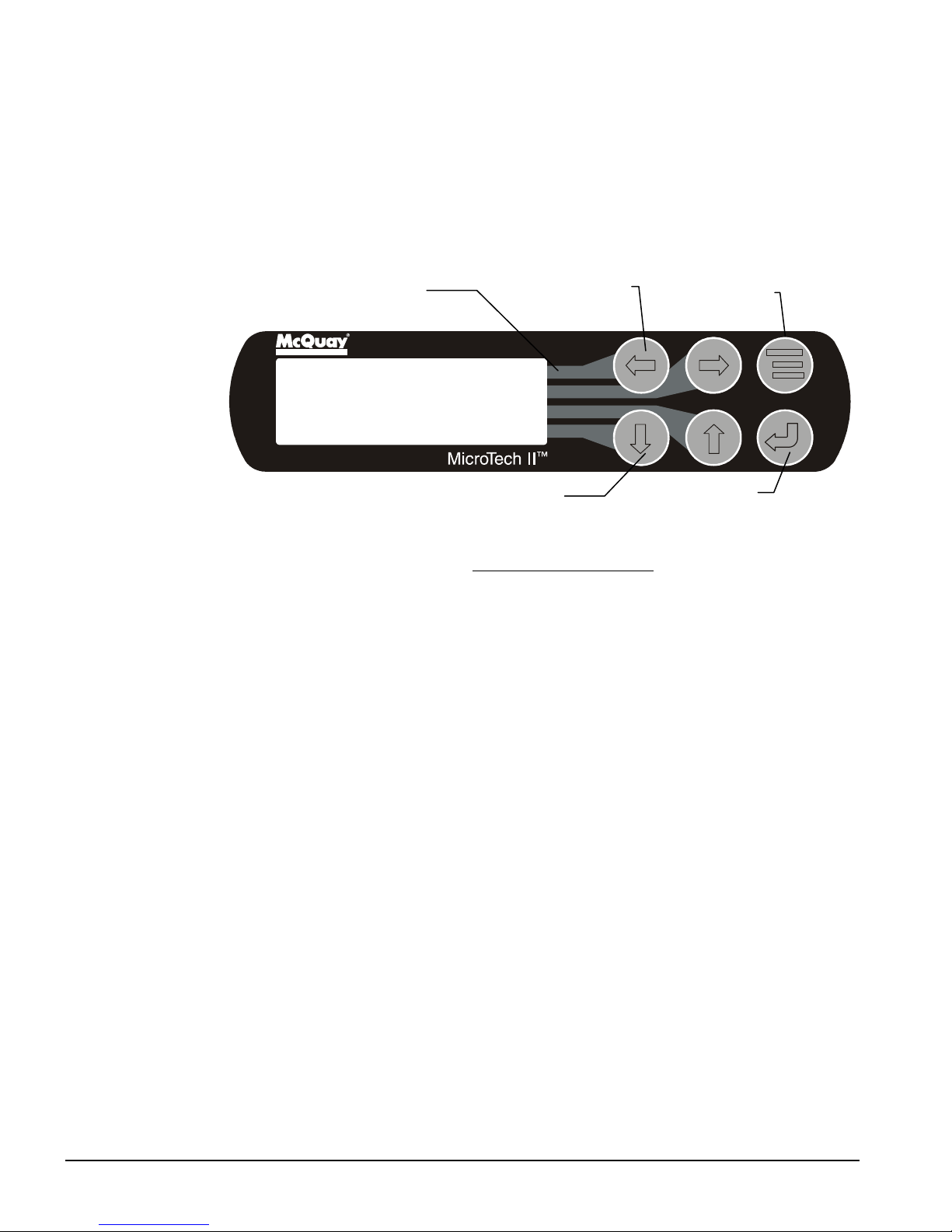
Liquid Line Solenoid
ALARM
Red Alarm Light
The liquid line output shall be on any time a compressor is running and the unit is not
performing a pumpdown. This output should be off at all other times.
Using the Controller
4x20 Display & Keypad
The 4-line by 20-character/line liquid crystal display and 6-key keypad are shown below.
Figure 15, Display (in MENU Mode) and Keypad Layout
Key to Screen Pathway
Air Conditioning
MENU Key
<
VIEW
<
<
SET
ARROW Keys (4)
ENTER Key
Note that each ARROW key has a pathway to a line in the display. Pressing an ARROW
key will activate the associated line when in the MENU mode.
Getting Started
There are two basic procedures to learn in order to utilize the MicroTech II controller:
1. Navigating through the menu matrix to reach a desired menu screen and knowing where
a particular screen is located.
2. Knowing what is contained in a menu screen and how to read that information or how
to change a setpoint contained in the menu screen.
Navigating Through the Menus
The menus are arranged in a matrix of screens across a top horizontal row. Some of these
top-level screens have sub-screens located under them. The general content of each screen
and its location in the matrix are shown in Figure 17. A detailed description of each menu
begins on page 51.
There are two ways to navigate through the menu matrix to reach a desired menu screen.
One is to scroll through the matrix from one screen to another using the four ARROW keys.
The other way is to use shortcuts to work through the matrix hierarchy. From any menu
screen, pressing the MENU key will take you to the top level of the hierarchy. The display
will show ALARM, VIEW, and SET as shown in Figure 15. This corresponds to the second
row of screens on Figure 17. One of these groups of screens can then be selected by
pressing the key connected to it via the pathway shown in Figure 15.
For example, selecting ALARM will go the next row of menus under ALARM (ALARM
LOG or ACTIVE ALARM). Selecting VIEW will go the next level of screens under VIEW
(VIEW UNIT STATUS or VIEW UNIT TEMP). Selecting SET will go to a series of
screens for looking at and changing setpoints.
48 AGZ 010B through 034B IOMM AGZB1
Page 49

MENU Key
The MENU key is used to switch between the shortcut method (known as the MENU mode
and as shown in Figure 15) and scrolling method (known as the SCROLL mode). The
MENU mode is the shortcut to specific groups of menus used for checking ALARMS, for
VIEWING information, or to SET setpoint values. The SCROLL mode allows the user to
move about the matrix (from one menu to another, one at a time) by using the four
ARROW keys. A typical menu screen is shown in Figure 16.
Pressing the MENU key from any menu screen will automatically return you to the MENU
mode as shown in Figure 15.
Figure 16, Display in the Shortcut (SCROLL) Mode and Keypad Layout
Air Conditioning
MENU Key
VIEW UNIT STATUS
Unit = COOL
Compr. #1/#2=OFF/OFF
Evap Pump = RUN
ARROW Keys
ENTER Key
Menu Screens
Various menus are shown in the controller display. Each menu screen shows specific
information; in some cases menus are used only to view the status of the unit, in some cases
they are used for checking and clearing alarms, and in some case they are used to set
setpoint values.
The menus are arranged in a matrix of screens across a top horizontal row. Some of these
top-level screens have sub-screens located under them. The general content of each screen
and its location in the matrix are shown in Figure 17. A detailed description of each menu
begins on page 51.
The ARROW keys on the controller are used to navigate through the menus. The keys are
also used to change numerical setpoint values contained in certain menus.
Changing Setpoints
Pressing the ENTER key changes the function of the ARROW keys to the editing function
as shown below:
LEFT key Default, changes a value to the factory-set default value.
RIGHT key Cancel, cancels any change made to a value and returns to the original setting.
UP key Increment, increases the value of the setting
DOWN key Decrement, decreases the value of a setting.
These four edit functions are indicated by one-character abbreviation on the right side of
the display (this mode is entered by pressing the ENTER key).
Most menus containing setpoint values have several different setpoints shown on one menu.
When in a setpoint menu, the ENTER key is used to proceed from the top line to the second
line and on downward. The cursor will blink at the entry point for making a change. The
ARROW keys (now in the edit mode) are used to change the setpoint as described above.
IOMM AGZB1 AGZ 010B through 034B 49
Page 50

When the change has been made, press the ENTER key to enter it. No setting is changed
until the ENTER key is pressed.
For example, to change the chilled water setpoint:
1. Press MENU key to go to the MENU mode (see Figure 15).
2. Press SET (the UP Key) to go to the setpoint menus.
3. Press UNIT SPs (the Right key) to go to setpoints associated with unit operation.
4. Press the DOWN key to scroll down through the setpoint menus to the third menu which
contains Evap LWT=XX.X°F.
5. Press the ENTER key to move the cursor down from the top line to the second line in
order to make the change.
6. Use the ARROW keys (now in the edit mode as shown above) to change the setting.
7. When the desired value is achieved, press ENTER to enter it. The cursor will
automatically move down.
At this point, the following actions can be taken:
1. Change another setpoint in this menu by scrolling to it with the ENTER key
2. Using the ENTER key, scroll to the first line in the menu. From there the ARROW keys
can be used to scroll to different menus.
50 AGZ 010B through 034B IOMM AGZB1
Page 51

SET UNIT SPs, (1)
SET UNIT SPs, (2)
SET UNIT SPs, (3)
SET UNIT SPs, (4)
SET UNIT SPs, (5)
SET UNIT SPs, (6)
(7)
SET UNIT SPs, (8)
SET UNIT SPs, (9)
Figure 17, Menu Matrix
UNIT COMP REFRIGERANT FANS
VIEW UNIT
STATUS 1-3
TEMP 1-3
(Right side of matrix continued from above)
"ALARM" MENUS "SET" MENUS
ALARM LOG (LAST)
TYPE, TIME
ALARM LOG
(NEXT TO LAST)
ALARM LOG
(SECOND TO LAST)
ALARM LOG
LAST 25 SHOWN ⇓
SET UNIT SPs,
SET UNIT SPs,
SET UNIT SPs,
SET UNIT SPs,
VIEW COMP #1
STATUS
⇐ Continued ⇐
ACTIVE ALARM
(1)
TYPE, TIME
ACTIVE ALARM
(2)
TYPE, TIME
ADDITIONAL
ACTIVE ALARM
(3)
CLEAR/VIEW
"VIEW" MENUS
VIEW COMP #2
STATUS
MODE
MODE
COOL/GLYCOL/
ICE
TEMP EVAP LWT
MISC
CLOCK
ENGLISH
PROTOCOL
EVAP OFFSET
COND OFFSET
(10) LWT OFFSET
(11) AMBIENT
OFFSET
(12) ENTER
PASSWORD
VIEW EVAP/COND PRESS (1) VIEW UNIT
VIEW EVAP APPROACH (2)
SET COMP
SPs (1)
STOP/START
SET COMP
SPs (2) INTER-
STAGE
SET LIMIT
SET LIMIT
SET LIMIT
SET LIMIT
ALARMS (1)
EVAP PRESS
SET LIMIT
ALARMS (2)
FREEZE/ FLOW
ALARMS (3)
COND PRESS
ALARMS (4)
PHASE/VOLT
LOW AMB
LOCKOUT
ALARMS (5)
LOW EVAP PR
"MENU"
VIEW FAN
STAGING
SET FANS (1)
STAGES
FANTROL
SET FANS (2)
STAGE ON
SET FANS (3)
STAGE OFF
Menu Structure (Hierarchical)
As discussed previously, a hierarchical menu structure can be used to access the various
screens. One to twelve levels are used with two or three being typical. Optionally, the last
menu selection can access one of a set of screens that can be navigated with the UP/DOWN
ARROW keys (see the scrolled menu structure below).
IOMM AGZB1 AGZ 010B through 034B 51
Page 52

Menu selection is initiated by pressing the MENU key that changes the display from a
ALA RM LO G
regular data screen to a menu screen. Menu selections are then made using the arrow keys
according to labels on the right side of the display (the arrows are ignored). When the last
menu item is selected, the display changes to the selected data screen. An example follows
showing the selection of the “VIEW COMPRESSOR (n) screen.
Suppose the initial screen is as below or any other menu screen:
(da ta )
(da ta )
(da ta )
After pressing the MENU key, the top level menu screen will show:
< ALARM
< VIEW
< SET
After pressing the “VIEW” menu key, a menu screen will show:
VIEW < UNIT
< COMPRESSOR
< REFRIGRANT
< FANS
Selection of any of these will advance to the appropriate data menu. For example, after pressing the
“REFRIGERANT” menu button, the selected data screen will show:
VIEW REFRIG
PSI °°°°F
SAT EVAP XXX.X XX.X
SAT COND XXX.X XX.X
The ARROW keys will automatically return to the “scroll” mode at this time.
Screen Definitions VIEW
This section contains information on each screen. The menu screens are in order of the
matrix in Figure 17, going from left to right and then down when there are sub-menus.
Many menus are self-explanatory.
VIEW UNIT
VIEW UNIT STATUS (1)
Unit = AUTO
Cool Stages=0
Evap Pump = RUN
52 AGZ 010B through 034B IOMM AGZB1
Page 53

Unit states can be:
Ice Delay=xxhr XX mn
VIEW UNIT TEMP (1)
VIEW UNIT TEMP (2)
VIEW UNIT TEMP (3)
Auto Off:Ice Mode Timer Off:All Comps Disabled
Off:Unit Alarm Off:Keypad Disable Off:Remote Switch
Off:BAS Disable Off:Unit Switch Auto:High LWT Pulldn
Auto:Cycle Timers Auto:Wait for load Auto:OAT Lockout
Auto:Evap Recirc Auto:Wait for flow Auto:Pumpdown
Auto:Evap Press Low Auto:Cond Press High Off:Test Mode
as determined from the Unit State variable, the Unit Mode setpoint, the Unit Enable and the
presence of an alarm.
Pump states can be:
Off Start Run
VIEW UNIT STATUS (2)
Stg Up Delay=XXX sec
Stg Dn Delay=XXX sec
Ice delay line is only visible when in the ICE mode.
VIEW UNIT STATUS (3)
D.O. D.I.
12345678 123456
00000000 000000
Evap LWT = XX.X°°°°F
Outside Amb = XX.X°°°°F
LWT Target = XX.X°°°°F
LWT Pulldn=XX.X °°°°F/m
Control Band=XX.X °°°°F
StgUp@ XX.X Dn@ XX.X
Start Unit @ XX.X
Shutdown Unit @ XX.X
See page 39 for an explanation of these settings.
VIEW COMPRESSORS
VIEW COMP#1 (1)
State = OFF LEAD
Cycle Timer: XXmin
Manual Disable
Cycle timer only visible when active. Manual Disable visible only when compressor is
disabled via manual enable setpoint.
IOMM AGZB1 AGZ 010B through 034B 53
Page 54

VIEW COMP#1 (2)
Hours = XXXXX
Starts = XXXXX
Above two screens duplicated for compressor #2.
VIEW REFRIGERANT
VIEW REFRIG (1)
EVAP Press = XX.Xpsi
COND Press - XX.Xpsi
With R22 Refrigerant With R407C Refrigerant
VIEW REFRIG (2) VIEW REFRIG (2)
SAT EVAP = XXX.X°°°°F Evap Dew = XXX.X°°°°F
SAT COND = XXX.X°°°°F Cond Mid = XXX.X°°°°F
EvapApproach = XX.X°°°°F EvapApproach = XX.X°°°°F
See page 40 for an explanation of saturated temperatures for R22 and R407C.
Approach is the difference between the leaving fluid temperature and the saturated
evaporator temperature. It is an indication of the evaporator efficiency; an increasing
approach temperature indicates decreasing heat transfer efficiency.
VIEW FANS
VIEW FANS
Stages ON = X of X
Screen Definitions – ALARM
ALARM ACTIVE (X) ALARM ACTIVE (X)
Alarm Description No more alarms
hh:mm:ss dd/mmm/yyyy Press ENTER to clear
all active alarms
If the unit is off on a shutdown alarm or running but in a limit alarm condition, the cause
and date will appear in the upper screen. If there is a simultaneous occurrence of more than
one alarm, the others will appear in additional screens below this one, accessed by the
DOWN ARROW. Either type alarm will light a red light in back of the LEFT-KEY. The
light will go out when the fault is cleared.
To clear the fault, scroll down to the last screen and press ENTER. If other faults have
appeared, they will all be cleared at the same time.
54 AGZ 010B through 034B IOMM AGZB1
Page 55
ALARM LOG (1)
h Condenser Press
Hig
hh:mm:ss d/mmm/yyyy
The last 25 alarms, either shutdown or limit, are shown in this menu with subsequent menus
stored under it. ARROW DOWN from this menu will go to the next-to-last alarm, ARROW
DOWN again will go to the second from last, and so on through the last 25 occurrences.
The screens are numbered (1), (2), (3), etc.
Screen Definitions – SET
Changing setpoints; in general, setpoints are changed as follows:
1. Select the desired menu by scrolling through SET menus with the UP and DOWN
ARROWS.
2. When the desired menu is selected, select the desired entry by moving between lines
using the ENTER key.
3. If a numerical value is being changed, use the INCREMENT key (UP ARROW) to
increase or the DECREMENT key (DOWN ARROW) to decrease the value of the
setpoint.
If a word type setpoint (for example, YES or NO) is to be selected, the choices are
loaded into the menu and selected by scrolling through the available setpoint options
using the UP ARROW key.
4. Enter the desired value or word into the controller by pressing the SET key.
SET UNIT SETPOINTS (SP)
SET UNIT SPs (1)
Unit Enable=OFF
Mode=COOL
Source=KEYPAD
Unit Enable is an external signal or a keypad setting that keeps the unit off when the setting
is OFF and allows it to run if there is a call for cooling. The source for the signal is
selected in the 4th line and can be:
1. KEYPAD, in which case the selection is made in line 2 and would be normally selected
as ON. This is the normal setting when no external signals are controlling the unit.
2. SWITCHES, in which an external switch is wired across terminals #25 and #35. (See
wiring diagram page 27).
3. NETWORK, used with BAS signal, which is wired to the three communication ports.
Unit Mode settings can be
1. COOL, normal setting used with chilled water air-condition applications.
2. COOL w/GLYCOL, used with low temperature, glycol applications. It allows a lower
LWT setpoint to be used.
3. ICE w/GLYCOL, used with ice storage systems, allows changing from chilled glycol
operation to lower temperature ICE operation. In ICE, the unit runs at full load until
the ICE setpoint is reached, at which time the unit shuts off. A three-position switch
wired to terminals #28 and #38 initiates the change from glycol cooling to making ice.
(See wiring diagram on page 27.)
IOMM AGZB1 AGZ 010B through 034B 55
Page 56

Set w/ FP Switch Off
T UNIT SPs (3)
SET UNIT SPs (2)
Available Modes
=COOL w/Glycol
Available Modes settings can be COOL, COOL w/Glycol, ICE w/Glycol, or TEST as
selected from the available modes imbedded in the menu. The 4th line is a reminder that the
ON/OFF switch on the front panel (FP) must be in the OFF position before the MODE can
be changed. This prevents a mode change while the unit is operating.
SE
Evap LWT = XX.X°°°°F
Ice LWT = XX.X°°°°F
EvapDeltaT= XX.X°°°°F
SET UNIT SPs (4)
StartDelta= XX.X°°°°F
StopDelta= XX.X°°°°F
Staging
StartDelta is the number of degrees above the temperature setting that determines when the
lead compressor starts. Compressor start and stop is determined by the control band and
StartDelta settings. The control band is automatically set of 60% of the EvapDeltaT
(chilled water temperature in minus chilled water temperature out) selected in menu 3
above. The staging routine has been changes in this software version compared to previous
versions. See page 39 for more details and an example.
For a warm start-up the lead compressor will start at any temperature above the start
temperature. The lag will start after the start interval has timed out. The chilled water
temperature will begin to be pulled down. At shut down temperature, the lag compressor
will shut off. If the temperature climbs above that temperature within the StageDownTimer
setting (default at 30 sec.), the lead compressor will remain on. This would be normal
operation. If for some reason the temperature does not rise, the lead compressor will also
shut off.
SET UNIT SPs (5)
Max Pulldn=X.X°°°°F/min
Evap Recirc= XXX sec
LowAmbLock= XX.X °°°°F
SET UNIT SPs (6)
Ice Time Delay=XXhrs
Clear Ice Delay=No
56 AGZ 010B through 034B IOMM AGZB1
Page 57

SET UNIT SPs (7)
CLOCK
dd/mmm/yyyy
hh:mm:ss
SET UNIT SPs (8)
Units = °°°°F/psi
Lang = ENGLISH
Refrig = Select Type
Units settings are only °F/psi at the present time. °C/kPa will be available later.
Lang (Language) settings can be only ENGLISH at present.
Refrig (Refrigerant) selection is done at the factory prior to shippment.
SET UNIT SPs (9)
Protocol = NONE
Ident Number=001
Baud Rate=9600
SET UNIT SPs (10)
Evaporator Refrig
Press Sensor
Offset= 00.0 psi
The pressure/temperature offsets on menus 10 through 13 correct the controller's display of
the parameters. The sensors used in these units have a high degree of repeatability but may
need correction (offset). An accurate pressure gauge or thermometer is used to determine
the correct temperature or pressure. A positive or negative offset value is then entered to
make the controller reading agree with the measured value.
SET UNIT SPs (11)
Condenser Refrig
Press Sensor
Offset= 00.0 psi
SET UNIT SPs (12)
Leaving Evaporator
Water Temp Sensor
Offset= 00.0oF
SET UNIT SPs (13)
Outside Ambient
Temperature Sensor
Offset= 00.0oF
IOMM AGZB1 AGZ 010B through 034B 57
Page 58

SET UNIT SPs (14)
ENTER PASSWORD XXXX
Active Password
Level:None
Two four-digit passwords provide OPERATOR and MANAGER levels of access to
changeable parameters. The passwords are preprogrammed into the controller. The
Operator Password is 0100. Either password must be entered using the ENTER
PASSWORD (12) screen before a protected setting can be changed.
This screen can be accessed either through the SET OTHER menu or by simply pressing
the ENTER key while on one of the SET screens. The controller will automatically go
from the screen with the setting change to this screen. After the correct password has been
entered, the controller will automatically return to the original set screen.
Once a password has been entered, it remains valid for 15 minutes after the last key-press.
SET COMP SPs
SET COMP SPs (1)
Clear Cycle Tmr=No
Stop-Start =XXmin
Start-Start =XXmin
This menu sets the anti-recycle timers. Stop-Start is the time required before starting a
compressor after it has stopped. Start-Start is the time required before starting a
compressor after the last time it has started. It recommended that these default values not
be changed.
SET COMP SPs (2)
InterStageUp=XXXsec
InterStageDn=XXXsec
InterStageUp is the time delay since the last stage change before a compressor can stage on.
InterStageDn is the time delay since the last stage change before a compressor can stage off
normally (not by an alarm).
SET COMP SPs (3)
Compressor 1=Enable
Compressor 2=Enable
ALARM SETPOINTS
SET ALARM LMTS (1)
LowEvPr
Hold=XXXpsi
Unload=XXXpsi
58 AGZ 010B through 034B IOMM AGZB1
Page 59
The LowEvPrHold and LowEvPrUnld have the same default value of 59 psi. If two
compressors are running, the LowEvPrUnld is in effect and the lag compressor will be shut
off to unload the unit. If one compressor is running, the LowEvPrHold is in effect and the
lag compressor is prevented from starting, thereby holding the unit capacity.
The last action to take place is the shutoff of all compressors running when the
LowEvPrStop setting is reached (default is 58 psi).
SET ALARM LMTS (2)
Evap Freeze= XX.X°°°°F
EvapFlowProof=XXXsec
Evap Freeze (the unit freeze protection shutdown) is actually a stop alarm and shuts off the
unit when the LWT reaches 36°F. It is cleared by going to the CLEAR ALARM menu in
the ACTIVE ALARM hierarchy.
EvapFlowProof is the flow switch interlock. Closing the flow switch and therefor proving
the existence of chilled water flow resets this trip.
SET ALARM LMTS (3)
High Cond Pressure
Unload = XXXpsi
Stop = XXXpsi
HighCondPr (the unit high-discharge-pressure shutdown) is a stop alarm that shuts off the
unit when the discharge pressure reaches the setting. The default setting is 380 psi. The
Stop is a shutdown alarm that stops the unit when the discharge pressure reaches the
setpoint.
SET ALARM LMTS (4)
PhaseVoltage=YES/NO
LowOATLockTmr=XXXsec
LowAmbientLock prevents unit operation below the setting. If the unit is equipped with
the standard FanTrol pressure-activated control, the available range is 35°F to 60°F with a
default of 35°F. With the optional SpeedTrol variable speed control, the range becomes
–2°F to 60°F with default of 0°F. Input to line 3 of the next screen, SET FANS SP (1),
informs the controller which type of control is installed and which range of setting to allow.
SET FANS STAGES
SET FANS SPs (1)
Fan Stages= X
Speedtrol = NO
The Fans line tells the controller the number of fans on the unit. The UP ARROW toggles
between 1, 2, and 3. 1 is not used; 2 should be used for Models AGZ 010, 013, and 017;
and 3 should be used for AGZ 020, 025, 029, and 034.
IOMM AGZB1 AGZ 010B through 034B 59
Page 60

Speedtrol tells the controller whether the optional SpeedTrol is installed in the unit. The
#1 #2 #3
XXX XXX XXX
3
UNIT XXX XXX
vap Water Pump=OFF
UP ARROW toggles between YES and NO. The setting changes the range available: YES
= 35°F to 60°F, with 35°F being the recommended setting; NO = -2°F to 60°F, with 0°F
being the recommended setting.
SET FANS SPs (2)
Stage ON psi
SET FANS SPs (3)
Stage Off psi
#1 #2 #
These two menus set the on and off staging pressures for the fans. The third fan stage
setting is only for three fan units. These settings are used with both FanTrol and
SpeedTrol. SpeedTrol takes effect when the last fan is running after FanTrol cycles off the
others.
Screen Definitions – TEST
The test screens are only available when the unit is in TEST mode. Using these screens,
any digital output can be controlled manually.
TEST UNIT (1)
Alarm Signal= OFF
E
TEST UNIT (2)
Liquid Line Sol=OFF
Compressor #1 = OFF
Compressor #2 = OFF
TEST UNIT (3)
Fan Motor #1 = OFF
Fan Motor #2 = OFF
Fan Motor #3 = OFF
60 AGZ 010B through 034B IOMM AGZB1
Page 61
Editing, Review
Editing is accomplished by pressing the ENTER key until the desired field is selected. This
field is indicated by a blinking cursor under it. The arrow keys shall then operate as
defined below.
CANCEL ................... Reset the current field to the value it had when editing began.
DEFAULT................. Set value to original factory setting.
INCREMENT ............ Increase the value or select the next item in a list.
DECREMENT ........... Decrease the value or select the previous item in a list.
During edit mode, the display shall show a two-character-wide menu pane on the right as
shown below.
SET UNIT SPs (X) <D
(data) <C
(data) <+
(data) <-
Additional fields can be edited by pressing the ENTER key until the desired field is
selected. When the last field is selected, pressing the ENTER key switches the display out
of “edit” mode and returns the ARROW keys to “scroll” mode.
BAS Interface
McQuay’s Protocol Selectability feature is available as a factory-installed option or as a retrofit
item available for installation after the unit is shipped.
If an interface module was ordered, one of the following BAS interface installation manuals was
shipped with the equipment. Additional copies of referenced McQuay documents may be obtained
from the local McQuay sales office, from the local McQuay Factory Service office, from the
McQuay Technical Response Center, located in Staunton, Virginia (540-248-0711) or downloaded
from www,mcquay.com.
• IM 735, LONW
• IM 736, BACnet Communication Module Installation
• IM 743, Modbus Communication Module Installation
• ED 15062-0, Microtech II Chiller Protocol Information – BACnet and LONW
• ED 15063-0, Microtech II Chiller Unit Controller Protocol Information – Modbus
The above are trademarks or registered trademarks of their respective companies: BACnet from the
American Society of Heating, Refrigerating and Air-Conditioning Engineers, Inc., LonTalk,
LONMARK and LONWORKS from Echelon Corporation, and Modbus and ModbusRTU from
Schneider Electric.
ORKS
Communication Module Installation
ORKS
IOMM AGZB1 AGZ 010B through 034B 61
Page 62

Service
Thermostatic Expansion Valve
!
WARNING
Disconnect and tag out all power sources to the unit before doing any service inside the
unit. Failure to do so can cause severe personal injury or death.
!
CAUTION
Service on this equipment is to be performed by qualified service personnel with special
regard to regulations concerning release of refrigerant to the atmosphere.
Note: Repeated tripping of equipment protection controls must be investigated and
corrected.
The expansion valve is responsible for allowing the proper amount of refrigerant to enter
the evaporator regardless of cooling load. It does this by maintaining a constant superheat.
(Superheat is the difference between refrigerant temperature as it leaves the evaporator and
the saturation temperature corresponding to the evaporator pressure.) Typically, superheat
should run in the range of 8°F to 12°F (4.4°C to 6.6°C).
The superheat setting can be adjusted by removing the cap at the bottom of the valve to
expose the adjustment screw. Turn the screw clockwise (when viewed from the adjustment
screw end) to increase the superheat setting and counterclockwise to reduce superheat.
Allow time for system rebalance after each superheat adjustment.
The expansion valve, like the solenoid valve, should not normally require replacement, but
if it does the unit must be pumped down by following the steps involved when changing a
filter-drier.
If the problem can be traced to the power element only, unscrew the element from the valve
body without removing the valve, but only after pumping the unit down.
Filter-Driers
If the pressure drop across the filter-drier is in the 6 to 10 psi range, it should be monitored
and changed when the pressure drop reaches 10 psi. To change the liquid line sealed filter,
de-energize the unit and pump out the refrigerant. After changing the filter-drier, check for
leaks before recharging and returning unit to operation.
Liquid Line Solenoid
The liquid line solenoid valve does not normally require any maintenance. It may, however,
require replacement of the solenoid coil. The solenoid coil may be removed from the valve
body without opening the system by disconnecting power to the unit. The coil can then be
removed from the valve body by simply removing the nut or snap ring located at the top of
the coil.
62 AGZ 010B through 034B IOMM AGZB1
Page 63

Optional Controls
SpeedTrol Head Pressure Control
The SpeedTrol method of head pressure control operates in conjunction with FanTrol by
modulating the motor speed on system #1 fan in response to condenser pressure. By
reducing the speed of the last fan as the condensing pressure falls, the unit can operate to
0°F (-18°C) ambient air temperature.
The SpeedTrol fan motor is a single-phase, 230/460 volt, thermally protected motor
specially designed for variable speed operation. The solid-state speed control is mounted in
the unit control panel and is connected to a Schrader fitting on the liquid line. The control
is factory-set to start modulating fan speed at 230 psig, and it will maintain a minimum
condensing pressure of 170 to 180 psig. Minimum starting voltage for SpeedTrol motors is
120 volts.
A low ambient timer function is included in the microprocessor. When the solenoid valve
and lead compressor are energized by the controller, the low pressure cutout control is
bypassed and the compressor is allowed to start with the low pressure control open.
After about 2-3/4 minutes, the time delay will open and the low pressure cutout function is
again operable. If the system has not built up enough evaporator pressure to close the low
pressure setting, the compressor will stop.
Due to the vertical condenser design, it is recommended that the unit be oriented so that
prevailing winds blow parallel to the unit length, thus minimizing effects on minimum
ambient operation. If it is not practical to orient the unit in this manner, a wind deflector
should be constructed.
Hot Gas Bypass
Hot gas bypass is a system for maintaining evaporator pressure at or above a minimum
value. The purpose for doing this is to keep the velocity of the refrigerant as it passes
through the evaporator high enough for proper oil return to the compressor when cooling
load conditions are light. It also maintains continuous operation of the chiller at light load
conditions.
The solenoid valve should be wired to open whenever the liquid line solenoid valve is
energized. This can be accomplished by wiring the hot gas solenoid (SV5) in parallel with
the liquid line solenoid at terminals 14 and 16. The pressure-regulating valve is factory-set
to begin opening at 58 PSIG (32°F for R-22) when the air-charged bulb is in an 80°F
ambient temperature. The bulb can be mounted anywhere as long as it senses a fairly
constant temperature at various load conditions. The compressor suction line is one such
mounting location. It is generally in the 50°F to 60°F range.
Figure 19 indicates that when the bulb is sensing 50°F to 60°F temperatures, the valve will
begin opening at 54 PSIG. This setting can be changed as indicated above, by changing the
pressure setting, remove the cap on the bulb and turn the adjustment screw clockwise. To
lower the setting, turn the screw counterclockwise. Do not force the adjustment beyond the
range it is designed for, as this will damage the adjustment assembly.
The regulating valve opening point can be determined by slowly reducing the system load
(or increasing the required chiller water temperature setting indicated on the unit
thermostat), while observing the suction pressure. When the bypass valve starts to open,
the refrigerant line on the evaporator side of the valve will begin to feel warm to the touch.
IOMM AGZB1 AGZ 010B through 034B 63
Page 64
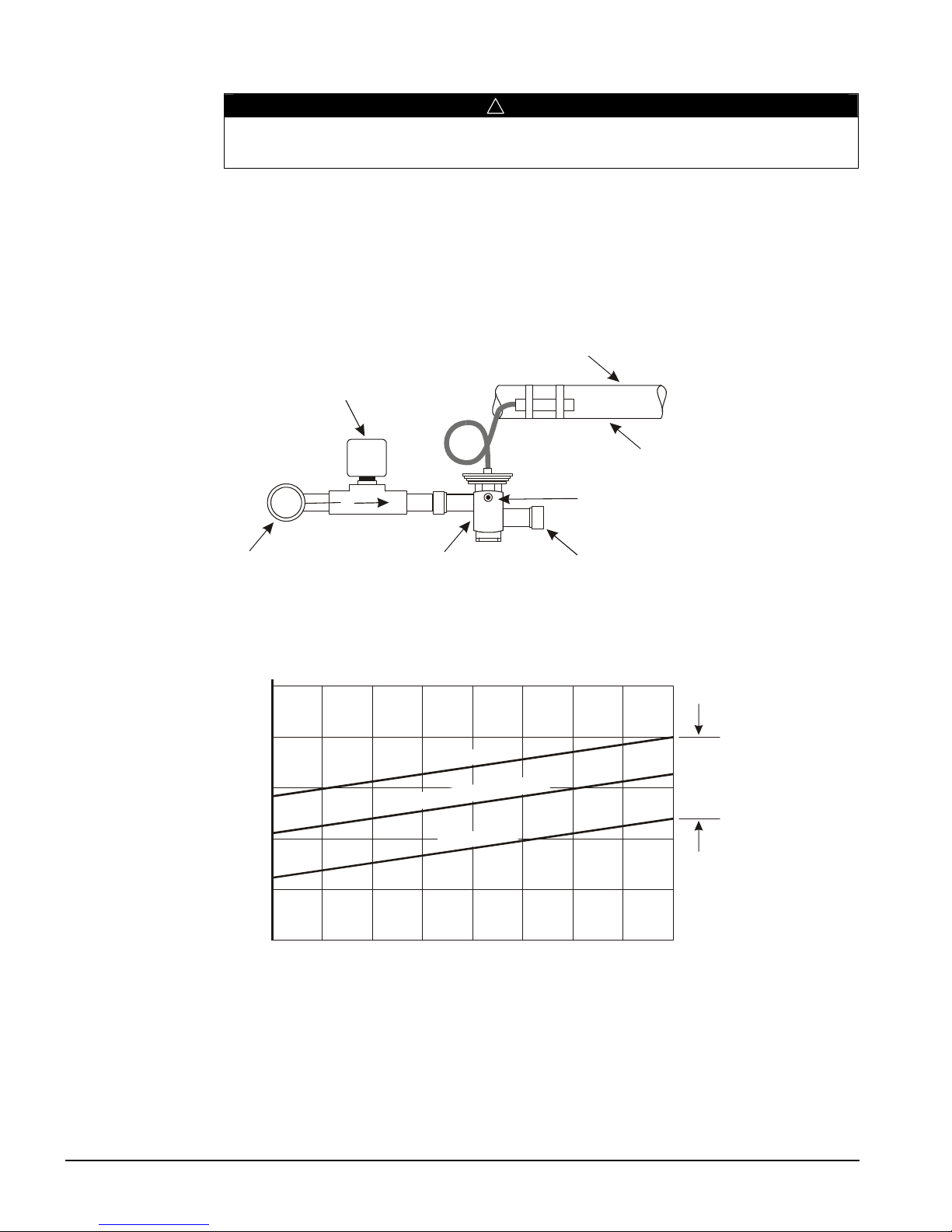
Bypass Valve
Suction Line
Remote Bulb
External Equalizer
Connection to Suction
After Expansion Valve
8090100
110
G
P
R
E
S
S
U
R
E
(
P
S
I
G
)
!
WARNING
The hot gas line may become hot enough to cause injury in a very short time. Avoid
contact during valve checkout.
On installations where the condensing unit is remote from the evaporator, it is
recommended that the hot gas bypass valve be mounted near the condensing unit to
minimize the amount of refrigerant that will condense in the hot gas line during periods
when hot gas bypass is not required.
Figure 18, Hot Gas Bypass Piping
Hot Gas Bypass
Solenoid Valve
Adjustable
Side of Evaporator
Discharge
Hot Gas
Line
Figure 19, Hot Gas Bypass Adjustment
80
70
60
50
40
VALVE OPENIN
30
30 40 50 60 70
REMOTE BULB ADJUSTMENT RANGE
M
U
M
I
X
A
M
G
N
I
T
T
E
S
Y
R
O
T
C
A
F
M
U
M
I
N
I
M
TEMP (°F) AT BULB LOCATION
To Evaporator Inlet
RANGE
ADJUSTMENT
MODEL AGZ 029 – 034, Post 2004 Production
Model AGZ 029 and 034 built after January 2004 may have a hot gas bypass valve as
shown as shown in Figure 20.
64 AGZ 010B through 034B IOMM AGZB1
Page 65

The valve is adjusted using the adjusting screw show in the drawing. The range is 0 to 100
psi with about 16 psi change for one turn of the screw. Turning clockwise will increase the
valve setting.
The load must be varied to properly set these valves. The load should be decreased so that
the suction pressure decreases. The valve is then adjusted to maintain the correct suction
pressure, which is the normal pressure at full load. The load should then be increases above
the valve setting so that it closes. Operation can be checked by again reducing the load and
noting when the valve opens (a hissing sound and/or pressure rise at the valve outlet
indicates that the valve has opened).
Figure 20, ACZ 033 - 039 Hot Gas Bypass Valve
Adjusting Screw
IOMM AGZB1 AGZ 010B through 034B 65
Page 66
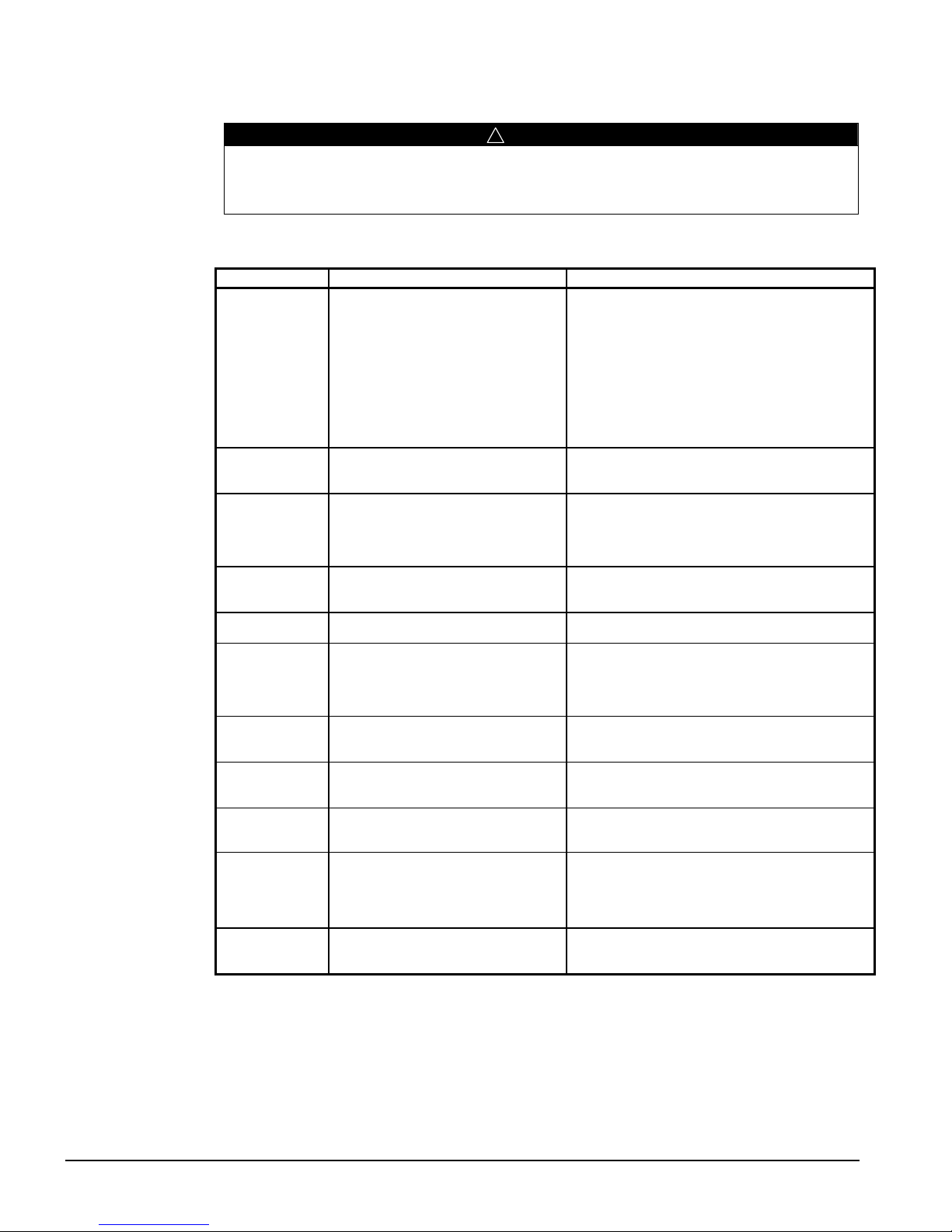
Troubleshooting Chart
Troubleshooting can present risks of severe personal injury or death from burns, cuts,
electrocution, strangulation and asphyxiation. Troubleshooting must be done by trained,
experienced technicians only.
Table 22, Troubleshooting Chart
PROBLEM POSSIBLE CAUSES POSSIBLE CORRECTIVE STEPS
1. Main switch open
2. Fuse blown, breakers open
COMPRESSOR
WILL NOT RUN
COMPRESSOR
NOISY OR
VIBRATING
HIGH
DISCHARGE
PRESSURE
LOW
DISCHARGE
PRESSURE
HIGH SUCTION
PRESSURE
LOW SUCTION
PRESSURE
UNIT WILL NOT
LOAD OR
UNLOAD
LOAD/UNLOAD
INTERVAL TOO
SHORT
COMPRESSOR
LOSES OIL
MOTOR
OVERLOAD
RELAYS OPEN
OR BLOWN
FUSES
COMPRESSOR
THERMAL
SWITCH OPEN
3. Thermal overloads tripped
4. Defective contactor or coil
5. System off by protection device
6. No cooling required
7. Liquid line solenoid will not open
8. Motor electrical problem
9. Loose wiring
1. Refrigerant flooding compressor
2. Improper line support
3. Worn compressor
1. Noncondensables in system
2. Refrigerant overcharge
3. Fan not running
4. Dirty condenser coils
5. FanTrol out of adjustment
1. Faulty condenser control
2. Low refrigerant charge
3. Low suction pressure
1. Excessive load
2. Expansion valve overfeeding
1. Lack of refrigerant
2. Evaporator dirty
3. Clogged filter-drier
4. Expansion valve malfunctioning
5. Low condensing temperature
1 Faulty controller sensor/broken wire
2. Stages not set for application
1. Erratic water thermostat
2. Insufficient water flow
1. Lack of refrigerant
2. Suction superheat too high
3. Crankcase heater burned out
1. Low voltage during high loads
2. Defective or grounded motor wiring
3. Loose power wiring
4. High condensing temperature
5. Unbalanced voltage
1. Operating beyond design conditions 1. Add facilities so conditions are within allowable
!
WARNING
1. Close switch
2. Check electrical circuits and motor windings for
shorts. Check for overloads and loose
connections. Replace fuse or reset breaker.
3. Check unit when back on line, auto reset
4. Repair or replace
5. Determine cause and correct
6. None, should start on call for cooling
7. Repair or replace coil
8. Check motor for open or short circuit, or burnout
9. Check all wire junctions. Tighten all terminals.
1. Check expansion valve setting
2. Relocate or add supports
3. Replace
1. Remove with authorized procedures
2. Remove excess
3. Check electrical circuit
4. Clean coil
5. Adjust FanTrol setting
1. Check condenser control operation
2. Check for leaks. Add refrigerant
3. See low suction pressure steps below
1. Reduce load or add capacity
2. Check remote bulb. Regulate superheat
1. Check for leaks. Repair and replace refrigerant.
2. Clean chemically
3. Replace
4. Check and adjust for proper superheat
5. Check discharge pressure control settings
1. Replace
2. Adjust thermostat setting
1. Replace
2. Adjust flow
1. Check for leaks and repair
2. Adjust superheat
3. Replace crankcase heater
1. Check supply voltage
2. Replace compressor
3. Check all connections and tighten
4. See steps for high discharge pressure
5. Check voltage. Contact power company.
limits
66 AGZ 010B through 034B IOMM AGZB1
Page 67

Page 68

All McQuay equipment is sold pursuant to McQuay’s Standard Terms and Conditions of
Sale and Limited Product Warranty.
This document contains the most current product information as of this printing. For the
most up-to-date product information, please go to www.mcquay.com
800 432 1342• www.mcquay.com IOMM AGZB1 (10/07)
 Loading...