

Page 1
Operation Manual
Air-Cooled Scroll Compressor Chiller
Packaged and Remote Evaporator
AGZ 026BS/M through 130BS/M
60 Hertz
R-22, R407c
Software Version AGZDU0102C
OM AGZ-1
Group: Chiller
Part Number: 331374101
Effective: July 2007
Supercedes: January 2007
Page 2
Table of Contents
Introduction........................................3
General Description.....................................3
Nomenclature...............................................3
Ambient Air Temperature Limitations.........4
Water Flow Limitations ...............................5
System W ater Volume Considerations.........5 Pre Start-up.................................................54
Variable Speed Pumping..............................5 Start-Up......................................................54
Glycol Solutions ..........................................6 Shutdown ...................................................55
Operating/Standby Limits..........................10 Water Piping Checkout ..............................55
R-407C Units ....................................13
MicroTech II Controller..................15
Controller Section Table of Contents.........15
Overview....................................................16
General Description...................................16
Setpoints ....................................................18
Logging......................................................20
Control Logic............................................. 21
Chilled Water Pump Control......................22
Compressor Control...................................22
Condenser Fan Control..............................26
Low Ambient Startup.................................28
Evaporator Pressure Control......................29
Optional Low Ambient VFD......................29
Using the Controller...................................39
Building Automation System Interface (BAS)
....................................................................53
Startup..............................................54
Refrigerant Piping Checkout......................55
Electrical Check Out..................................56
Operation .........................................56
Hot Gas Bypass (Optional) ........................56
VFD Low Ambient Control (Optional)......57
Filter-Driers................................................57
System Adjustment.....................................57
Liquid Line Sight Glass .............................57
Refrigerant Charging..................................57
Thermostatic Expansion Valve...................58
Crankcase Heaters......................................58
Evaporator..................................................58
Phase Voltage Monitor (Optional)..............58
Our facility is ISO Certified
"McQuay" is a registered trademark of McQuay International
Illustrations and data cover McQuay International products at the time of publication and we reserve the right
to make changes in design and construction at anytime without notice.
©2005 McQuay International
2 AGZ 026B through 130B OM AGZ-1
Page 3

Introduction
General Description
McQuay Air-Cooled Global Water Chillers are complete, self-contained automatic
refrigerating units. Every unit is completely assembled, factory wired, charged, and
tested. Each unit consists of twin air-cooled condensers with integral subcooler
sections, two tandem or triple scroll compressors, brazed-plate or replaceable tube, dual
circuit shell-and-tube evaporator, and complete refrigerant piping. Liquid line
components include manual liquid line shutoff valves, sight-glass/moisture indicators,
solenoid valves, and thermal expansion valves. Other features include compressor
crankcase heaters, an evaporator heater for chilled water freeze protection, limited
pumpdown during “on” or “off” periods, automatic compressor lead-lag to alternate the
compressor starting sequence, and sequenced starting of compressors.
The electrical control center includes all equipment protection and operating controls
necessary for dependable automatic operation. Condenser fan motors are protected in
all three phases and started by their own three-pole contactors.
This manual covers units with software version AGZDU0102C. Installation,
maintenance and service information is in IMM AGZ-7 (or current latest dash number)
manual.
BOOT Version 3.0F
BIOS Version 3.56
Air-Cooled
Global
Scroll Compressor
Nomenclature
A G Z - XXX B S
Application
S= Standard Ambient, Packaged
M= Standard Ambient, Remote
H= High Ambient, Packaged
B= High Ambient, Remote
Design Vi ntage
Model Size
(Nominal Tons)
OM AGZ-1 AGZ 026B through 130B 3
Page 4
Ambient Air Temperature Limitations
Standard/High Ambient Panels
Models AGZ-B (26 to 130 tons, two circuit) have electrical data and subsequent field wiring
requirements that are tailored to individual applications.
There are many installations where the expected summer ambient air temperatures will be at
105°F (40.1°C) or less, resulting in smaller unit electrical requirements compared to operation at
106°F (41.1) and above. In these lower temperature cases, there can be considerable installation
cost savings by using smaller and more appropriate electrical service.
Therefore, the AGZ electrical data is divided into two classifications based on the design ambient
temperature where the unit will operate. Standard Ambient unit electrical data (BS and BM
models) is for operation in ambient temperatures of 105°F (40.1°C) or less. Units with the High
Ambient designation (BH and BB models) are for use above 105°F (40.1°C) to 125°F (51.7°C).
The AGZ-B units for high ambient operation require the addition of the High Ambient Control
Panel Option, which includes the addition of a small fan with a filter in the air intake to cool the
control panel, and a unit nameplate that lists the larger electrical requirements.
All units with the optional VFD low ambient fan control automatically include the High Ambient
Control Panel Option. Operation of the VFD generates a quantity of panel heat best removed by
use of a control panel fan.
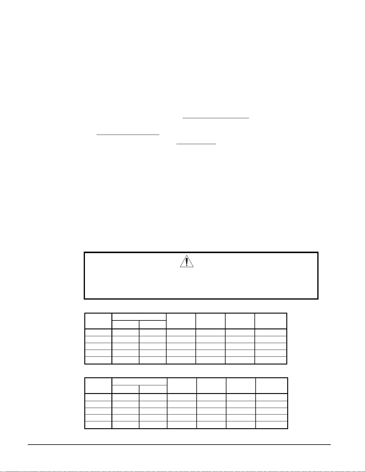
Winter Operation Temperatures
0°F to 34°F 35°F and Above
Fan Control Optional High VFD (1) Standard FanTrol (2)
Design Ambient Air Temperature
Electrical Data (3)
≤105°F >106°F ≤105°F >106°F
Standard
Ambient
High
Ambient
Standard
Ambient
High
Ambient
Panel Fan Required (4) Yes Yes No Yes
Model Designator (5)
Packaged BS BH BS BH
Remote Evaporator BM BB BM BB
NOTES
1. VFD is variable speed, fan control through the MicroTech Ii controller.
2. FanTrol is fan cycling off discharge pressure.
3. Standard Ambient and High Ambient electrical data is located in the installation and
maintenance manual.
4. The VFD option automatically includes the factory-installed panel fan and filter set
5. The designator is the last two characters in the model number, i.e. AGZ 100BS.
Panel Ratings
Vo ltage
208-230
240
380-460
575
Standard
Standard Options
Panel
Optional
VFD
High Short Circuit
Panel (kA)
High Interrupt Panel w/
Disconnect Swt. (kA)
35 5 120 120
35 5 100 100
35 5 65 65
5 5 25 25
4 AGZ 026B through 130B OM AGZ-1
Page 5
Water Flow Limitations
The evaporator flow rates and pressure drops shown on page 11 are for full load design purposes in
order to maintain proper unit control. The maximum flow rate and pressure drop are based on a 6degree temperature drop. Avoid higher flow rates with resulting lower temperature drops to prevent
potential control problems resulting from very small control bands and limited start up/shut off
temperature changes.
The minimum flow and pressure drop is based on a full load evaporator temperature drop of 16-degrees.
Evaporator flow rates below the minimum values can result in laminar flow causing freeze-up problems,
scaling and poor control. Flow rates above the maximum values will result in unacceptable pressure
drops and can cause excessive erosion, potentially leading to failure.
This full load minimum flow is not to be confused with the part load minimum flow rat e that must be
maintained for chillers operating in primary variable flow pumping systems. As chiller capacity drops,
the flow rate for this pumping system will reduce proportionally. See the following table for the part
load minimum flo w rates.
These minimum flow rates assume that flow will be reduced proportionally to the cooling load.
Table 1, Minimum Part Load Flow Rates
AGZ Model 026 030 035 040 045 050 055 060 065
Minimum Part
Load Flow (GPM)
AGZ Model 070 075 085 090 100 110 120 130
Minimum Part
Load Flow (GPM)
26 29 32 37 41 45 50 55 59
63 71 119 128 146 161 180 194
System Water Volume Considerations
All chilled water systems need adequate time to recognize a load change, respond to that load change
and stabilize, without undesirable short cycling of the compressors or loss of control. In air
conditioning systems, the potential for short cycling usually exists when the building load falls below
the minimum chiller plant capacity or on close-coupled systems with very small water volumes.
Some of the things the designer should consider when looking at water volume are the minimum
cooling load, the minimum chiller plant capacity during the low load period and the desired cycle time
for the compressors.
Assuming that there are no sudden load changes and that the chiller plant has reasonable turndown, a
rule of thumb of “gallons of water volume equal to two to three times the chilled water gpm flow rate”
is often used.
A properly designed storage tank should be added if the system components do not provide sufficient
water volume.
Variable Speed Pumping
Variable water flow involves reducing the water flow through the evaporator as the load decreases.
McQuay chillers are designed for this duty provided that the rate of change in water flow is not greater
than 10 percent of the change per minute.
The water flow through the vessel must remain between the minimum and maximum values listed on
11. If flow drops below the minimum allowable, large reductions in heat transfer can occur. If
page
the flow exceeds the maximum rate, excessive pressure drop and tube erosion can occur.
OM AGZ-1 AGZ 026B through 130B 5
Page 6
Glycol Solutions
T
The use of a glycol/water mixture in the evaporator to prevent freezing will reduce system capacity and
efficiency, as well as increase pressure drop. The system capacity, required glycol solution flow rate,
and pressure drop with glycol may be calculated using the following formulas and tables.
1. Capacity – Multiply the capacity based on water by the Capacity correction factor
Table 2 through Table 5.
from
2. Flow – Multiply the water evaporator flow by the Flow correction factor from
Table 2 through Table 5 to determine the increased evaporator flow due to glycol.
If the flow is unknown, it can be calculated from the following equation:
×
=
(gpm) Flow Glycol FactorCorrectionFlow
For Metric Applications
– Use the following equation for metric applications:
(l/s) Flow Glycol
CapacitykW
Delta
−×=18.4
3. Pressure drop -- Multiply the water pressure drop from page
correction factor from
Table 2 through Table 5. High concentrations of propylene
glycol at low temperatures may cause unacceptably high pressure drops.
4. Power -- Multiply the water system power by Power correction factor from
through
Table 5.
Test coolant with a clean, accurate glycol solution hydrometer (similar to that found in
service stations) to determine the freezing point. Obtain percent glycol from the
freezing point table below. It is recommended that a minimum of 25% solution by
weight be used for protection against corrosion or that additional compatible inhibitors
be added.
Concentrations above 35 percent do not provide any additional burst protection and
should be carefully considered before using.
glycolCapacityTons
)(24
−
TDelta
×
×
FactorCorrectionFlow
)
11 by Pressure Drop
Table 2
CAUTION
Do not use an automotive grade antifreeze. Industrial grade glycols must be
used. Automotive antifreeze contains inhibitors which will cause plating on the
copper tubes within the chiller evaporator. The type and handling of glycol used
must be consistent with local codes.
Table 2, Ethylene Glycol Factors for Models AGZ 026B to 070B
% E.G. Capacity Power Flow PD
10
20
30
40
50
Freeze Point
o
F
26 -3.3 0.998 0.998 1.036 1.097
18 -7.8 0.993 0.997 1.060 1.226
7 -13.9 0.987 0.995 1.092 1.369
-7 -21.7 0.980 0.992 1.132 1.557
-28 -33.3 0.973 0.991 1.182 1.791
o
C
Table 3, Propylene Glycol Factors for Models AGZ 026B to 070B
% P.G. Capacity Power Flow PD
10
20
30
40
50
Freeze Point
o
F
26 -3.3 0.995 0.997 1.016 1.100
19 -7.2 0.987 0.995 1.032 1.211
9 -12.8 0.978 0.992 1.057 1.380
-5 -20.6 0.964 0.987 1.092 1.703
-27 -32.8 0.952 0.983 1.140 2.251
o
C
6 AGZ 026B through 130B OM AGZ-1
Page 7
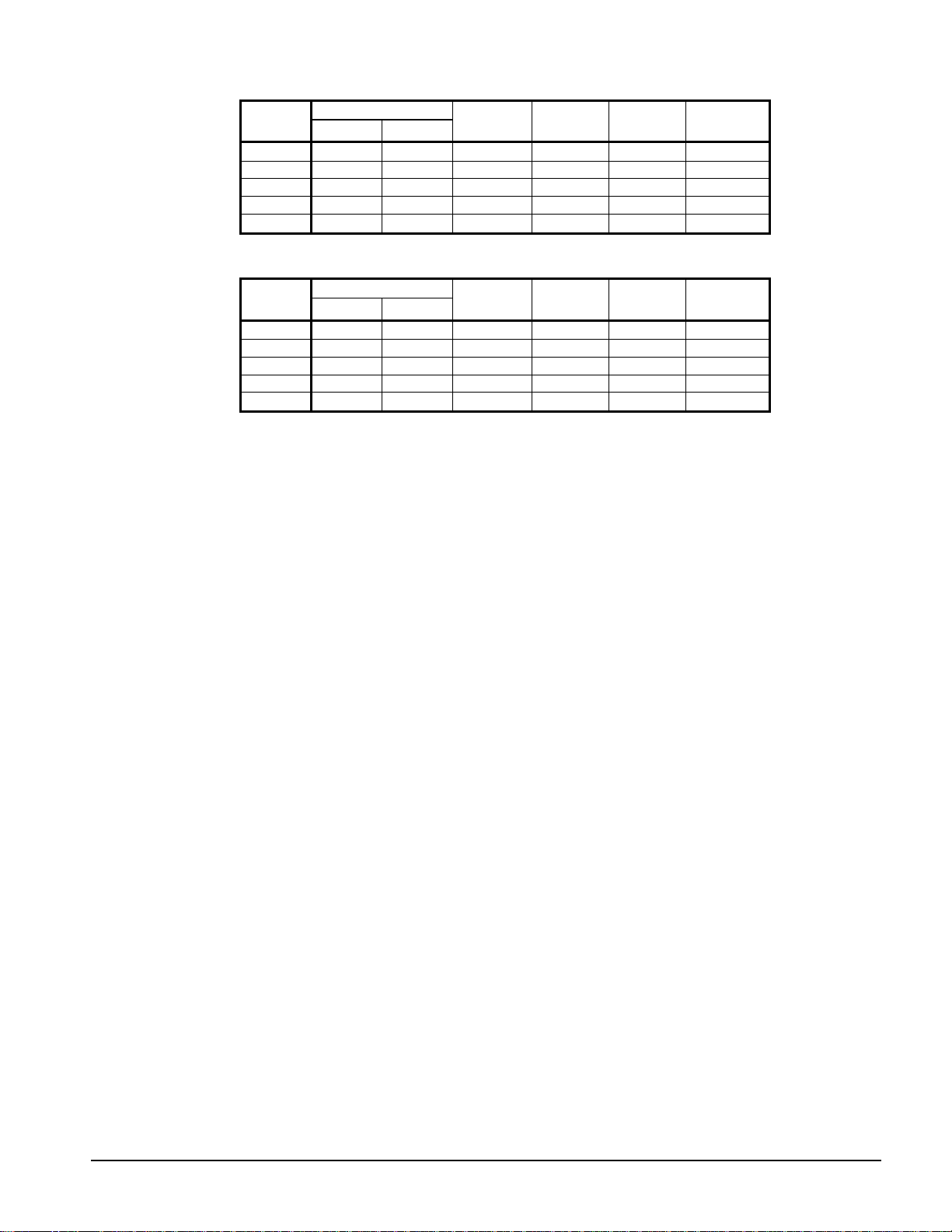
Table 4, Ethylene Glycol Factors for Models AGZ 075B to 130B
% E.G. Capacity Power Flow PD
10
20
30
40
50
Freeze Point
o
F
26 -3.3 0.994 0.998 1.038 1.101
18 -7.8 0.982 0.995 1.063 1.224
7 -13.9 0.970 0.992 1.095 1.358
-7 -21.7 0.955 0.987 1.134 1.536
-28 -33.3 0.939 0.983 1.184 1.755
o
C
Table 5, Propylene Glycol Factors for Models AGZ 075B to 130B
% P.G.
10
20
30
40
50
Freeze Point
o
F
26 -3.3 0.988 0.996 1.019 1.097
19 -7.2 0.972 0.992 1.035 1.201
9 -12.8 0.951 0.987 1.059 1.351
-5 -20.6 0.926 0.979 1.095 1.598
-27 -32.8 0.906 0.974 1.142 2.039
o
C
Capacity Power Flow PD
Altitude Correction Factors
Performance tables are based at sea level. Elevations other than sea level affect the performance of
the unit. The decreased air density will reduce condenser capacity consequently reducing the unit's
performance. For performance at elevations other than sea level, refer to
Table 6 and Table 7.
Evaporator Temperature Drop Factors
Performance tables are based on a 10°F (5°C) temperature drop through the evaporator. Adjustment
factors for applications with temperature ranges from 6°F to 16°F (3.3°C to 8.9°C) are in
Table 7.
Table 6 and
Temperature drops outside this 6°F to 16°F (3.3°C to 8.9°C) range can affect the control system's
capability to maintain acceptable control and are not recommended.
The maximum water temperature that can be circulated through the evaporator in a non-operating
mode is 100°F (37.8°C).
Fouling Factor
Performance tables are based on water with a fouling factor of
As fouling is increased, performance decreases. For performance at other than 0.0001 (0.0176)
fouling factor, refer to
Foreign matter in the chilled water system will adversely affect the heat transfer capability of
the evaporator and could increase the pressure drop and reduce the water flow. Maintain
proper water treatment to provide optimum unit operation.
22
per ARI 550/590-98.
)/0176.0(/0001.0
kWCmorBTUFhrft °×°××
OM AGZ-1 AGZ 026B through 130B 7
Page 8
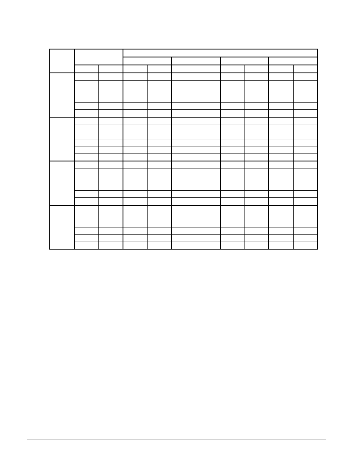
Table 6, Capacity and Power Derates, Models AGZ 026 to 070
Fouling Factor
Altitude
Sea
Level
2000 feet
4000 feet
6000 feet
Chilled Water Delta T
°F °C Cap. Power Cap. Power Cap. Power Cap. Power
6 3.3 0.978 0.993 0.975 0.991 0.963 0.987 0.940 0.980
8 4.4 0.989 0.996 0.986 0.994 0.973 0.990 0.950 0.983
10 5.6 1.000 1.000 0.996 0.999 0.984 0.994 0.961 0.987
12 6.7 1.009 1.003 1.005 1.001 0.993 0.997 0.969 0.990
14 7.7 1.018 1.004 1.014 1.003 1.002 0.999 0.978 0.991
16 8.9 1.025 1.007 1.021 1.006 1.009 1.001 0.985 0.994
6 3.3 0.977 1.001 0.973 1.000 0.961 0.996 0.938 0.989
8 4.4 0.987 1.006 0.984 1.004 0.971 1.000 0.948 0.993
10 5.6 0.998 1.009 0.995 1.007 0.982 1.003 0.959 0.996
12 6.7 1.007 1.011 1.004 1.010 0.991 1.006 0.967 0.998
14 7.7 1.014 1.014 1.011 1.013 0.998 1.009 0.974 1.001
16 8.9 1.022 1.016 1.018 1.014 1.005 1.010 0.981 1.003
6 3.3 0.973 1.011 0.970 1.010 0.957 1.006 0.935 0.998
8 4.4 0.984 1.014 0.980 1.013 0.968 1.009 0.945 1.001
10 5.6 0.995 1.019 0.991 1.017 0.979 1.013 0.955 1.005
12 6.7 1.004 1.021 1.000 1.020 0.987 1.016 0.964 1.008
14 7.7 1.011 1.024 1.007 1.023 0.994 1.018 0.971 1.011
16 8.9 1.018 1.027 1.014 1.026 1.002 1.021 0.978 1.014
6 3.3 0.969 1.021 0.966 1.020 0.954 1.016 0.931 1.008
8 4.4 0.980 1.026 0.977 1.024 0.964 1.020 0.942 1.013
10 5.6 0.989 1.029 0.986 1.027 0.973 1.023 0.950 1.015
12 6.7 0.998 1.033 0.995 1.031 0.982 1.027 0.959 1.020
14 7.7 1.007 1.036 1.004 1.034 0.991 1.030 0.967 1.022
16 8.9 1.014 1.037 1.011 1.036 0.998 1.031 0.974 1.024
0.0001 (0.0176) 0.00025 (0.044) 0.00075 (0.132) 0.00175 (0.308)
8 AGZ 026B through 130B OM AGZ-1
Page 9
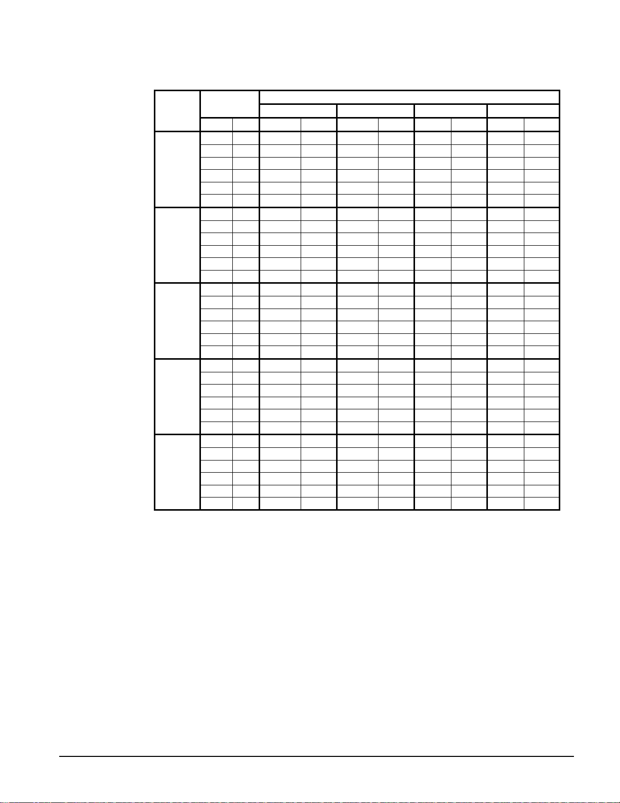
Table 7, Capacity and Power Derates, Models AGZ 075 to 130
Fouling Factor
Altitude
Sea
Level
2000 feet
4000 feet
6000 feet
8000 feet
Chilled Water
Delta T
°F °C Cap. Power Cap. Power Cap. Power Cap. Power
6 3.3 0.990 0.997 0.976 0.994 0.937 0.983 0.868 0.964
8 4.4 0.994 0.998 0.981 0.995 0.942 0.984 0.872 0.965
10 5.6 1.000 1.000 0.987 0.996 0.947 0.986 0.877 0.967
12 6.7 1.005 1.001 0.991 0.997 0.951 0.986 0.881 0.968
14 7.7 1.009 1.002 0.995 0.998 0.955 0.987 0.884 0.968
16 8.9 1.013 1.004 1.000 1.000 0.960 0.989 0.889 0.970
6 3.3 0.987 1.005 0.974 1.002 0.934 0.991 0.865 0.972
8 4.4 0.992 1.006 0.979 1.003 0.940 0.992 0.870 0.973
10 5.6 0.997 1.008 0.984 1.004 0.944 0.994 0.875 0.975
12 6.7 1.002 1.009 0.989 1.005 0.949 0.994 0.879 0.975
14 7.7 1.007 1.011 0.993 1.007 0.953 0.996 0.883 0.977
16 8.9 1.011 1.012 0.998 1.008 0.958 0.997 0.887 0.978
6 3.3 0.985 1.014 0.972 1.010 0.933 0.999 0.864 0.980
8 4.4 0.991 1.015 0.977 1.012 0.938 1.001 0.869 0.981
10 5.6 0.995 1.016 0.982 1.013 0.943 1.002 0.873 0.982
12 6.7 1.000 1.018 0.987 1.014 0.947 1.003 0.877 0.984
14 6.8 1.005 1.019 0.991 1.015 0.951 1.004 0.881 0.985
16 8.9 1.009 1.021 0.995 1.017 0.955 1.006 0.884 0.987
6 3.3 0.982 1.023 0.969 1.020 0.930 1.009 0.861 0.989
8 4.4 0.988 1.025 0.975 1.022 0.935 1.010 0.866 0.991
10 5.6 0.992 1.026 0.979 1.022 0.940 1.011 0.870 0.992
12 6.7 0.997 1.028 0.984 1.024 0.944 1.013 0.875 0.994
14 7.7 1.002 1.029 0.989 1.025 0.949 1.014 0.879 0.995
16 8.9 1.006 1.031 0.992 1.027 0.952 1.016 0.882 0.996
6 3.3 0.979 1.034 0.966 1.031 0.927 1.019 0.859 1.000
8 4.4 0.984 1.036 0.971 1.032 0.932 1.021 0.863 1.002
10 5.6 0.990 1.037 0.976 1.033 0.937 1.022 0.868 1.002
12 6.7 0.993 1.039 0.980 1.035 0.941 1.024 0.871 1.004
14 7.7 0.998 1.041 0.985 1.037 0.945 1.026 0.875 1.006
16 8.9 1.003 1.041 0.990 1.038 0.950 1.026 0.879 1.007
0.0001 (0.0176) 0.00025 (0.044) 0.00075 (0.132) 0.00175 (0.308)
Evaporator Freeze Protection
Evaporator freeze-up can be a concern in the application of air-cooled water chillers. To
protect against freeze-up, insulation and an electric heater cable are furnished with the
unit. This protects the evaporator down to -20°F (-29°C) ambient air temperature.
Although the evaporator is equipped with freeze protection, it does not protect water
piping external to the unit or the evaporator itself if there is a power failure or heater
cable burnout. Consider the following recommendations for additional protection.
1. If the unit will not be operated during the winter, drain evaporator and chilled water
piping and flush with glycol. Drain and vent connections are provided on the
evaporator to ease draining.
2. Add a glycol solution to the chilled water system to provide freeze protection.
Freeze point should be approximately ten degrees below minimum design ambient
temperature.
3. The addition of thermostatically controlled heat and insulation to exposed piping.
4. Continuous circulation of water through the chilled water piping and evaporator.
OM AGZ-1 AGZ 026B through 130B 9
Page 10

The evaporator heater cable is factory wired to the 115-volt circuit in the control box.
This power should be supplied from a separate source, but it can be supplied from the
control circuit. Operation of the heater cable is automatic through the ambient sensing
thermostat that energizes the evaporator heater cable for protection against freeze-up.
Unless the evaporator is drained in the winter, the disconnect switch to the evaporator
heater must not be open.
Operating/Standby Limits
Maximum standby ambient air temperature, 130°F (55°C)
Maximum operating ambient air temperature
Standard Ambient Unit, 105°F (40.6°C) and below, Models BS and BM
High Ambient Unit, above 105°F (40.6°C) to 125°F 51.7°C), Models BH and BB
Minimum operating ambient temperature (standard), 35°F (2°C)
Minimum operating ambient temperature (with optional low-ambient control), 0°F (-
18°C)
Leaving chilled water temperature, R-22, 40°F to 60°F (4.4°C to 15.6°C)
Leaving chilled water temperature, R-407C, 42°F to 60°F (5.5°C to 15.6°C)
Leaving chilled fluid temperatures (with anti-freeze), 20°F to 60°F (-7°C to 16°C
Design chilled water Delta-T range, 6 degrees F to 16 degrees F (3.3 degrees C to 8.9
degrees C)
Part load minimum flow for variable flow systems, varies with unit size, see table
below.
Maximum operating inlet fluid temperature, 76°F (24°C)
Maximum non-operating inlet fluid temperature, 100°F (38°C)
Water Flow Limitations, Variable Flow
The full load, minimum flow limitation for constant flow is not to be confused with the
part load minimum flow rate that must be maintained for chillers operating in primary
variable flow pumping systems. As chiller capacity drops, the flow rate for this
pumping system will reduce proportionally. See the following table for the part load
minimum flo w rates.
Other design practices for variable flow systems requiring a range of evaporator flow
rates can be found below.
These minimum flow rates assume that flow will be reduced proportionally to the
cooling load.
Table 8, Minimum Part Load Flow Rates
AGZ Model 010 013 017 020 025 029 034 026 030 035 040 045
Minimum
Part Load
Flow (GPM)
AGZ Model 050 055 060 065 070 075 085 090 100 110 120 130
Minimum
Part Load
Flow (GPM)
10 13 15 20 22 27 33 26 29 32 37 41
45 50 55 59 63 71 119 128 146 161 180 194
10 AGZ 026B through 130B OM AGZ-1
Page 11
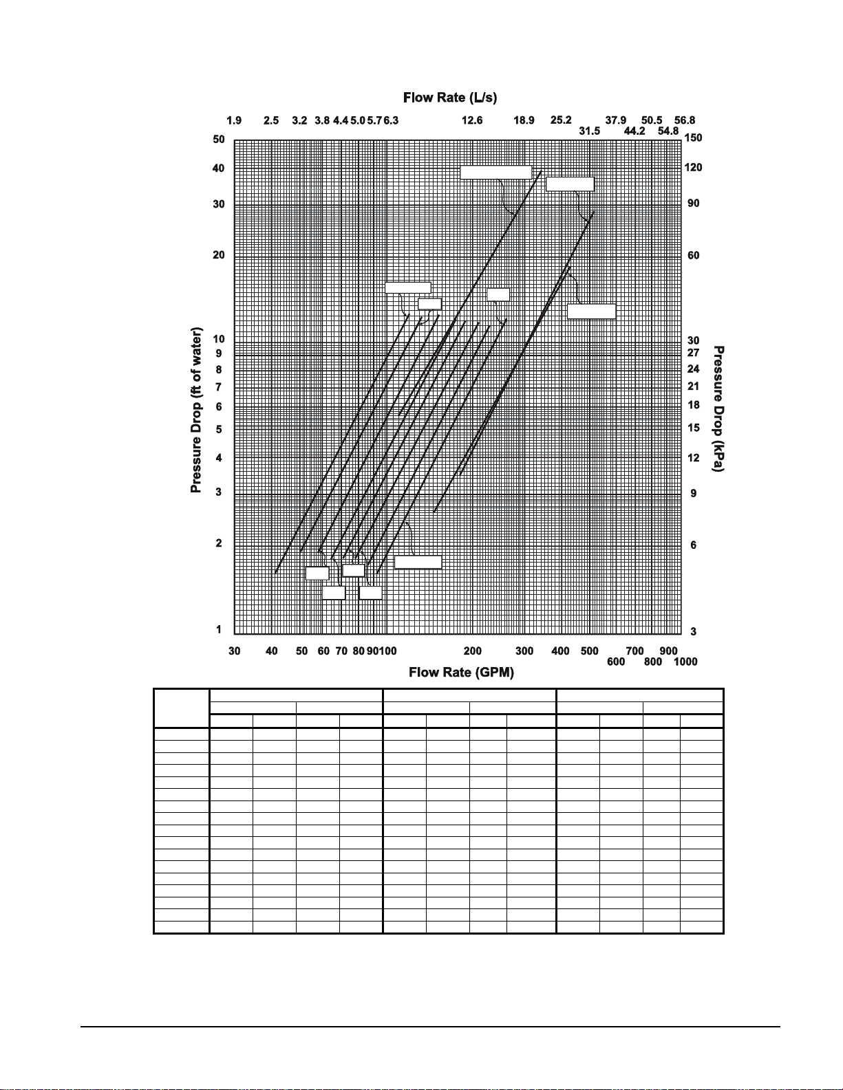
Figure 1, AGZ 026B – 130B, Evaporator Pressure Drop
040
045
050
055
026-030
065-070
035
075-085-090
120-130
060
100-110
AGZ Unit
Model
026B
030B
035B
040B
045B
050B
055B
060B
065B
070B
075B
085B
090B
100B
110B
120B
130B
NOTE: Minimum and maximum flows are established to ensure the Delta-T for each unit size falls within the 6 - 16°F range for
Inch-Pound S.I. Inch-Pound S.I. Inch-Pound S.I.
gpm DP ft. lps DP kpa gpm DP ft. lps DP kpa gpm DP ft. lps DP kpa
41 1.6 2.6 4.7 65 3.9 4.1 11.6 109 10.4 6.9 30.9
45 1.9 2.9 5.7 72 4.7 4.6 14.1 121 12.7 7.6 37.8
50 1.9 3.1 5.6 80 4.6 5.0 13.8 133 12.4 8.4 36.9
58 1.9 3.6 5.7 92 4.7 5.8 14.0 154 12.6 9.7 37.5
64 1.8 4.0 5.4 102 4.5 6.4 13.4 170 12.1 10.7 35.9
71 1.8 4.4 5.4 113 4.5 7.1 13.3 188 12.0 11.9 35.7
78 1.8 4.9 5.3 125 4.4 7.9 13.0 209 11.7 13.2 34.8
86 1.7 5.4 5.2 137 4.3 8.6 12.8 228 11.5 14.4 34.2
92 1.6 5.8 4.9 147 4.1 9.3 12.1 246 10.9 15.5 32.5
98 1.9 6.2 5.6 157 4.6 9.9 13.7 262 12.3 16.5 36.8
111 5.6 7.0 16.5 177 12.5 11.2 37.4 295 30.4 18.6 90.7
119 6.3 7.5 18.9 191 14.3 12.1 42.7 318 34.8 20.1 103.6
128 7.2 8.1 21.4 205 16.2 12.9 48.4 342 39.4 21.6 117.3
146 2.6 9.2 7.7 234 6.1 14.8 18.2 390 15.5 24.6 46.2
161 3.1 10.2 9.2 258 7.3 16.3 21.7 430 18.5 27.1 55.1
180 3.5 11.3 10.4 288 8.9 18.1 26.5 479 24.6 30.2 73.4
194 4.1 12.2 12.1 311 10.4 19.6 30.9 518 28.7 32.7 85.6
proper unit control.
OM AGZ-1 AGZ 026B through 130B 11
Minimum Nominal Maximum
Page 12
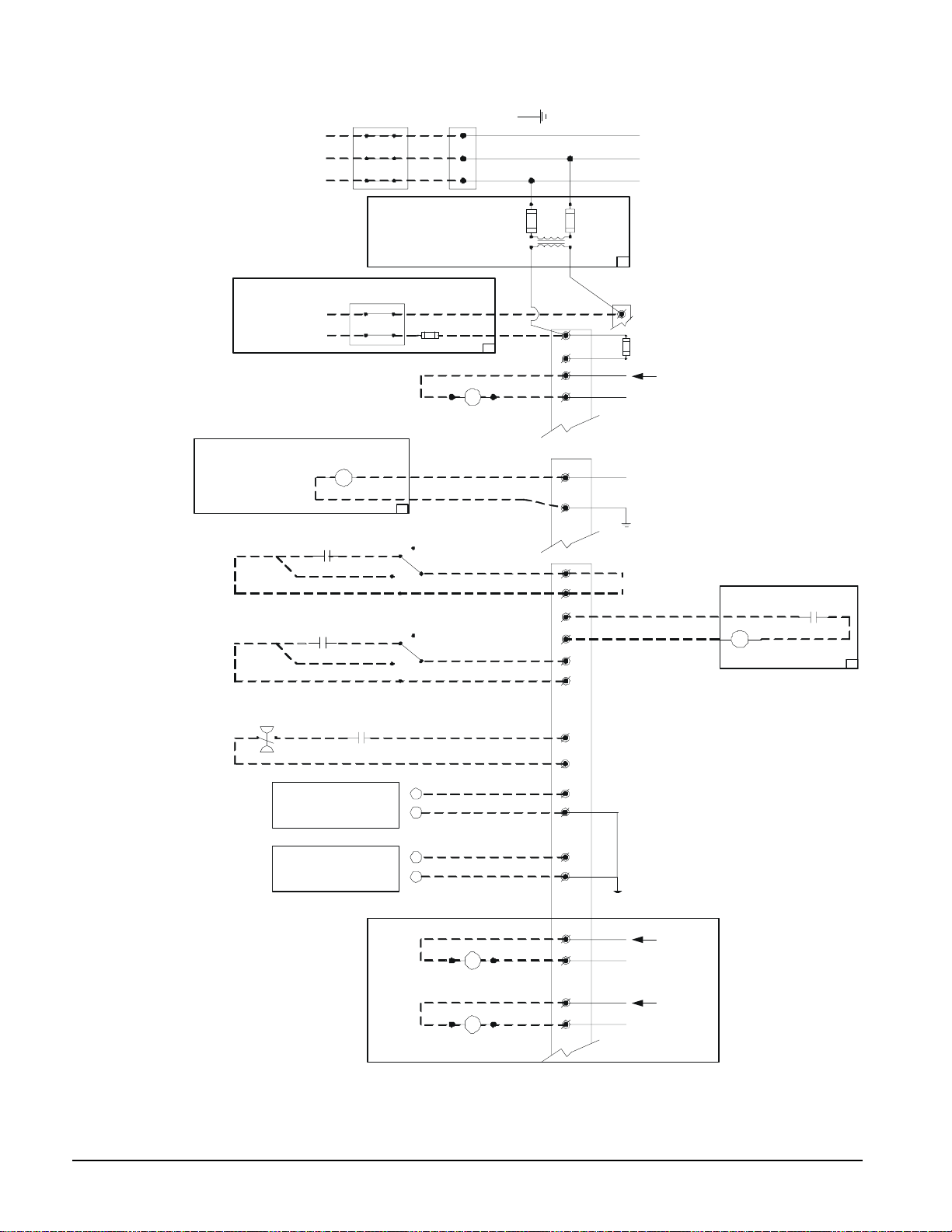
Figure 2, AGZ 026B – AGZ 130B, Typical Field Wiring
3 PHASE
POWER
DISCONNECT
(BY OTHERS)
UNIT MAIN
TERMINAL BLOCK
GND LUG
TO COMPRESSOR(S)
AND FAN MOTORS
NOTE: ALL FIELD WIRING TO BE
INSTALLED AS NEC CLASS 1
WIRING SYSTEM WITH CONDUCTOR
RATED 600 VOLTS
FIELD SUPPLIED
REMOTE STOP SWITCH
(BY OTHERS)
ICE MODE SWITCH
(BY OTHERS)
ALARM BELL
OPTION
CHW FLOW SWITCH
---MANDATORY–(BY OTHERS)
OPTION
CONTROL POWER
N
120VAC
FACTORY SUPPLIED ALARM
FIELD WIRED
ALARM BELL RELAY
TIME
CLOCK
FUSED CONTROL
CIRCUIT TRANSFORMER
DISCONNECT
(BY OTHERS)
10A
FUSE
(BY OTHERS)
CHW PUMP RELAY
120 VAC 1.0 AMP MAX
OFF
AUTO
ON
MANUAL
OFF
AUTO
ON
MANUAL
(BY OTHERS)
120 VAC
CONTROLLER
TB1
TB2
TB1-20
1
2
35
33
34
CONTROL
CIRCUIT
FUSE
120 VAC
N
120 VAC
32
GND
IF REMOTE STOP
52
72
43
83
54
CONTROL IS USED,
REMOVE LEAD 585
585
FROM TERM. 52
TO 72.
BELL
12
ALARM BELL OPTION
ALARM BELL
RELAY
COM NO
74
NOR. OPEN PUM P AUX.
CONTACTS (OPTIONAL)
44
61
4-20MA FOR
EVAP. WATER RESET
(BY OTHERS)
4-20MA FOR
DEMAND LIMIT
(BY OTHERS)
DWG. 330423101 REV.0A
+
-
+
-
LESS EVAPORATOR ONLY
LIQUID LINE #1 SOLENOID
24 VAC 1.5 AMP MAX
LIQUID LINE #2 SOLENOID
24 VAC 1.5 AMP MAX
68
69
70
71
GND
91
93
92
93
24 VAC
N
24 VAC
N
12 AGZ 026B through 130B OM AGZ-1
Page 13

R-407C Units
AGZ chillers are available with R-407C refrigerant as non-ARI certified units. R-407C is a
zeotropic blend of three compounds, and as such exhibits the characteristic of glide. It does
not behave as one substance like R-22 does. Glide is the difference (in degrees F) between the
beginning and end phase-change process in either the evaporator or condenser. During these
processes, different ratios of the refrigerant’s components change phase from the beginning to
the end of the process. The following functions, conditions and settings will differ from units
charged with R-22.
1. Polyolester lubricants are used instead of mineral oil.
2. The saturated pressure/temperature relationship
3. Control and alarm settings
4. Charging procedures
1. Lubrication. The units are factory-charged with polyoester (POE) lubricant and one of
the following lubricants must be used if lubricant is to be added to the system:
Copeland Ultra 22 CC
Mobil EAL™ Arctic 22 CC
ICI EMKARATE RL RL™ 32CF
POEs are very hydroscopic and will quickly absorb moisture if exposed to air. Pump the
lubricant into the unit through a closed transfer system. Avoid overcharging the unit.
2. Pressure/temperature relationship. See
temperature chart. Due to refrigerant glide, use the following procedures for superheat
and subcooling measurement.
To determine superheat, only vapor must be present at the point of measurement, no
liquid. Use the temperature reading, the pressure reading and the Saturated P/T Chart. If
the pressure is measured at 78 psig, the chart shows the saturated vapor
50.6°F. If the temperature is measured at 60°F, the superheat is 9.4 degrees F.
To determine subcooling, only liquid must be present, no vapor. Use the temperature
reading, the pressure reading and the Saturated P/T Chart. If the pressure is measured at
250 psig, the chart shows the saturated liquid
temperature is measured at 98°F, the subcooling is 10.2 degrees F.
The P/T relationship between R-407C and R-22 is similar enough to allow the use of R-22
expansion valves. The valves may be marked as “R-22’ or “R-22/R-407C”.
3. Control and alarm settings. The software that controls the operation of the unit is
factory-set for operation with R-407C, taking into account that the pressure/temperature
relationship differs from R-22. The software functionality is the same for either
refrigerant.
4. Charging procedure. The units are factory-charged with R-407C. Use the following
procedure if recharging in the field is necessary:
Whether topping off a charge or replacing the circuit’s entire charge, always remove the
refrigerant from the charging vessel as a liquid. Many of the cylinders for the newer
refrigerants have a dip tube so that liquid is drawn off when the cylinder is in the upright
position. Do not vapor charge out of a cylinder unless the entire contents will be charged
into the system.
Figure 3 on page 14 for the saturated pressure-
temperature to be
temperature to be 108.2°F. If the
With the system in a 250-micron or lower vacuum, liquid can be charged into the
high side. Initially charge about 80 percent of the system total charge.
OM AGZ-1 AGZ 026B through 130B 13
Page 14
Start the system and observe operation. Use standard charging procedures (liquid
only) to top off the charge.
It may be necessary to add refrigerant through the compressor suction. Because the
refrigerant leaving the cylinder must be a liquid, exercise care to avoid damage to
the compressor. A sight glass can be connected between the charging hose and the
compressor. It can be adjusted to have liquid leave the cylinder and vapor enter the
compressor.
Figure 3, R-407C Saturated Pressure/Temperature Chart
Pressure
(PSIG)
20 -10.7 1.5 150 74.8 84.9
22 -8.2 4.0 155 76.8 86.8
24 -5.7 6.4 160 78.7 88.7
26 -3.4 8.7 165 80.6 90.5
28 -1.1 11.0 170 82.5 92.3
30 1.1 13.1 175 84.3 94.0
32 3.2 15.2 180 86.1 95.8
34 5.3 17.2 185 87.8 97.5
36 7.3 19.2 190 89.6 99.1
38 9.2 21.0 195 91.3 100.7
40 11.1 22.9 200 92.9 102.3
42 12.9 24.7 205 94.6 103.9
44 14.7 26.4 210 96.2 105.4
46 16.4 28.1 215 97.7 107.0
48 18.1 29.7 220 99.3 108.4
50 19.7 31.3 225 100.8 109.9
52 21.3 32.9 230 102.3 111.4
54 22.9 34.4 235 103.8 112.8
56 24.4 35.9 240 105.3 114.2
58 25.9 37.4 245 106.7 115.6
60 27.4 38.8 250 108.2 116.9
62 28.8 40.2 255 109.6 118.2
64 30.2 41.6 260 111.0 119.6
66 31.6 43.0 265 112.3 120.9
68 33.0 44.3 270 113.7 122.1
70 34.3 45.6 275 115.0 123.4
72 35.6 46.9 280 116.3 124.7
74 36.9 48.1 285 117.6 125.9
76 38.2 49.3 290 118.9 127.1
78 39.4 50.6 295 120.2 128.3
80 40.6 51.8 300 121.4 129.5
82 41.9 52.9 305 122.7 130.7
84 43.0 54.1 310 123.9 131.8
86 44.2 55.2 315 125.1 133.0
88 45.4 56.3 320 126.3 134.1
90 46.5 57.4 325 127.5 135.2
92 47.6 58.5 330 128.7 136.3
94 48.7 59.6 335 129.8 137.4
96 49.8 60.7 340 131.0 138.5
98 50.9 61.7 345 132.1 139.6
100 51.9 62.7 350 133.2 140.6
105 54.5 65.2 355 134.3 141.7
110 57.0 67.7 360 135.4 142.7
115 59.5 70.0 365 136.5 143.7
120 61.8 72.3 370 137.6 144.7
125 64.1 74.6 375 138.7 145.7
130 66.4 76.7 380 139.8 146.7
135 68.5 78.8 385 140.8 147.7
140 70.7 80.9 390 141.8 148.7
145 72.8 82.9 395 142.9 149.6
Liquid Temp
(°F)
Vapor Temp
(°F)
Pressure
(PSIG)
Liquid Temp
(°F)
Vapor Temp
(°F)
14 AGZ 026B through 130B OM AGZ-1
Page 15

MicroTech II Controller
Software Version AGZDU0102B
Controller Section Table of Contents
Overview.............................................................................. 16
Inputs/Outputs ................................................................. 16
Setpoints ......................................................................... 18
Shutdown Alarms ............................................................ 19
Limit Alarms................................................................... 20
Control Logic.................................................................. 21
Compressor Control .......................................................22
Condenser Fan Control.................................................... 26
Using the Controller ............................................................. 30
Getting Started...................................................................... 39
Menu Screens.................................................................. 39
Menu Matrix ................................................................... 42
View Screens Defined ..................................................... 43
Alarm Screens Defined.................................................... 46
Set Screens Defined ........................................................ 46
Building Automation Systems (BAS)...............................53
OM AGZ-1 AGZ 026B through 130B 15
Page 16
Overview
MicroTech II controller’s state-of-the-art design not only permits the chiller to run more
efficiently, but also can simplify troubleshooting if a system failure occurs. Every
MicroTech II controller is programmed and tested prior to shipment to facilitate startup.
Operator-friendly
The MicroTech II controller menu structure is separated into three distinct categories
that provide the operator or service technician with a full description of 1) current unit
status, 2) control parameters, and 3) alarms. Security protection prevents unauthorized
changing of the setpoints and control parameters.
MicroTech II control continuously performs self-diagnostic checks, monitoring system
temperatures, pressures and protection devices, and will automatically shut down a
compressor or the entire unit should a fault occur. The cause of the shutdown will be
retained in memory and can be easily displayed in plain English for operator review.
The MicroTech II chiller controller will also retain and display the date/time the fault
occurred. In addition to displaying alarm diagnostics, the MicroTech II chiller
controller also provides the operator with a warning of limit (pre-alarm) conditions.
General Description
AGZ-B Inputs/Outputs
Table 9, Analog Inputs
No. Description Type Signal Source Range
1 Evaporator Refrigerant Pressure #1 C1 0 to 132 psi
2 Evaporator Refrigerant Pressure #2 C2 0 to 132 psi
3 Condenser Refrigerant Pressure #1 C1 3.6 to 410 psi
4 Leaving Evaporator Water Temperature UT NTC Thermister (10k@25°C) -58 to 212°F
5 Outside Ambient Temperature UT NTC Thermister (10k@25°C) -58 to 212°F
6 Condenser Refrigerant Pressure #2 C2 3.6 to 410 psi
7 Reset of Leaving Water Temperature UT 4-20 mA Current
8 Demand Limit UT 4-20 mA Current 0-100 % Load
9 Compressor Suction Temperature #1 C1 NTC Thermister (10k@25°C) -58 to 212°F
10 Compressor Suction Temperature #2 C2 NTC Thermister (10k@25°C) -58 to 212°F
NOTES:
1. C1 = Refrigerant Circuit #1, C2 = Refrigerant Circuit #2, UT = Unit
2. Value at the converter board input. Value at the converter board output is 0.1 VDC – 0.9 VDC.
0.5 - 4.5 VDC (NOTE 2)
0.5 - 4.5 VDC (NOTE 2)
0.5 - 4.5 VDC (NOTE 2)
0.1 to 0.9 VDC
Table 10, Analog Outputs
No. Description Output Signal Range
1 Fan #1 VFD 0 to 10 VDC 20 to 60 Hz
2 Fan #2 VFD 0 to 10 VDC 20 to 60 Hz
0 to10 degrees
60°F max inlet
16 AGZ 026B through 130B OM AGZ-1
Page 17
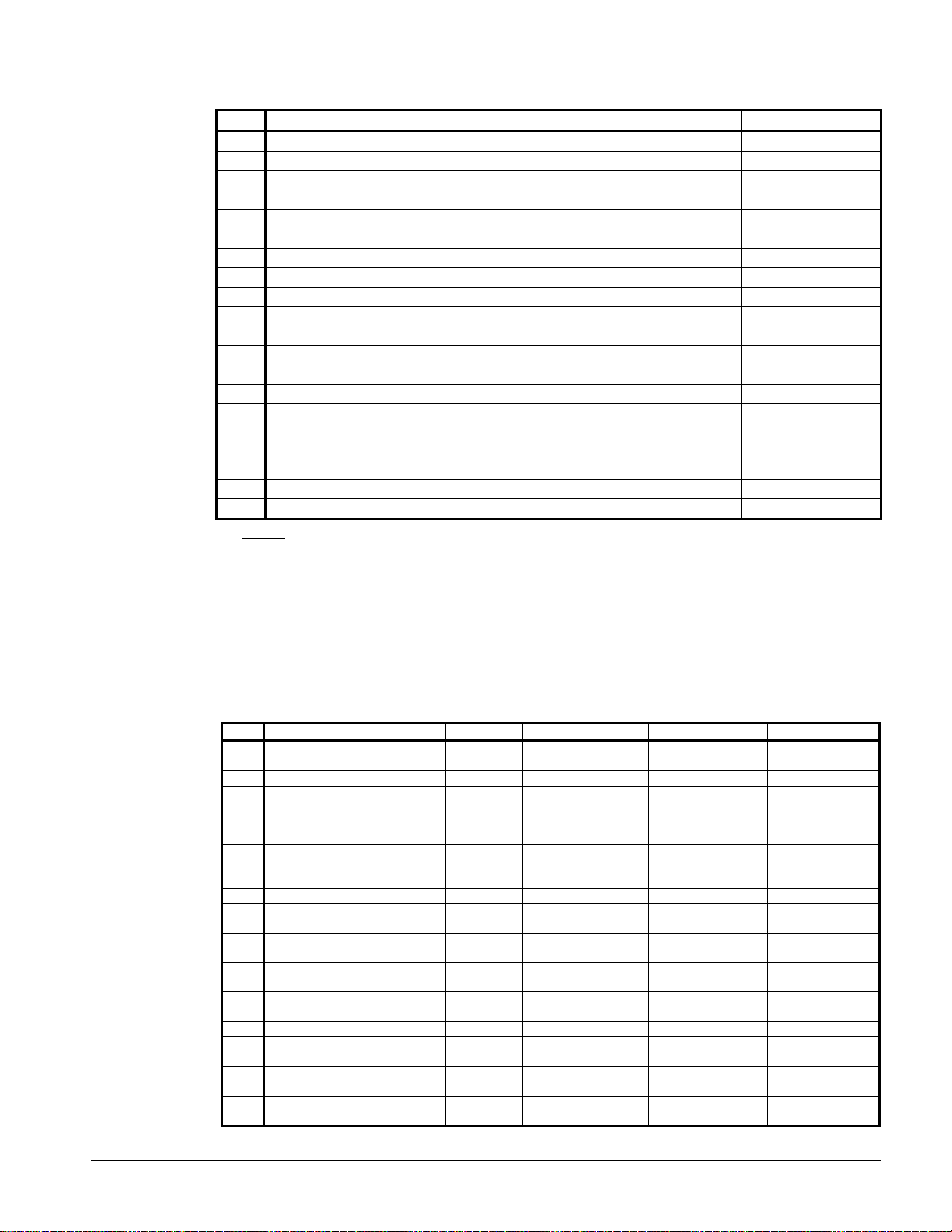
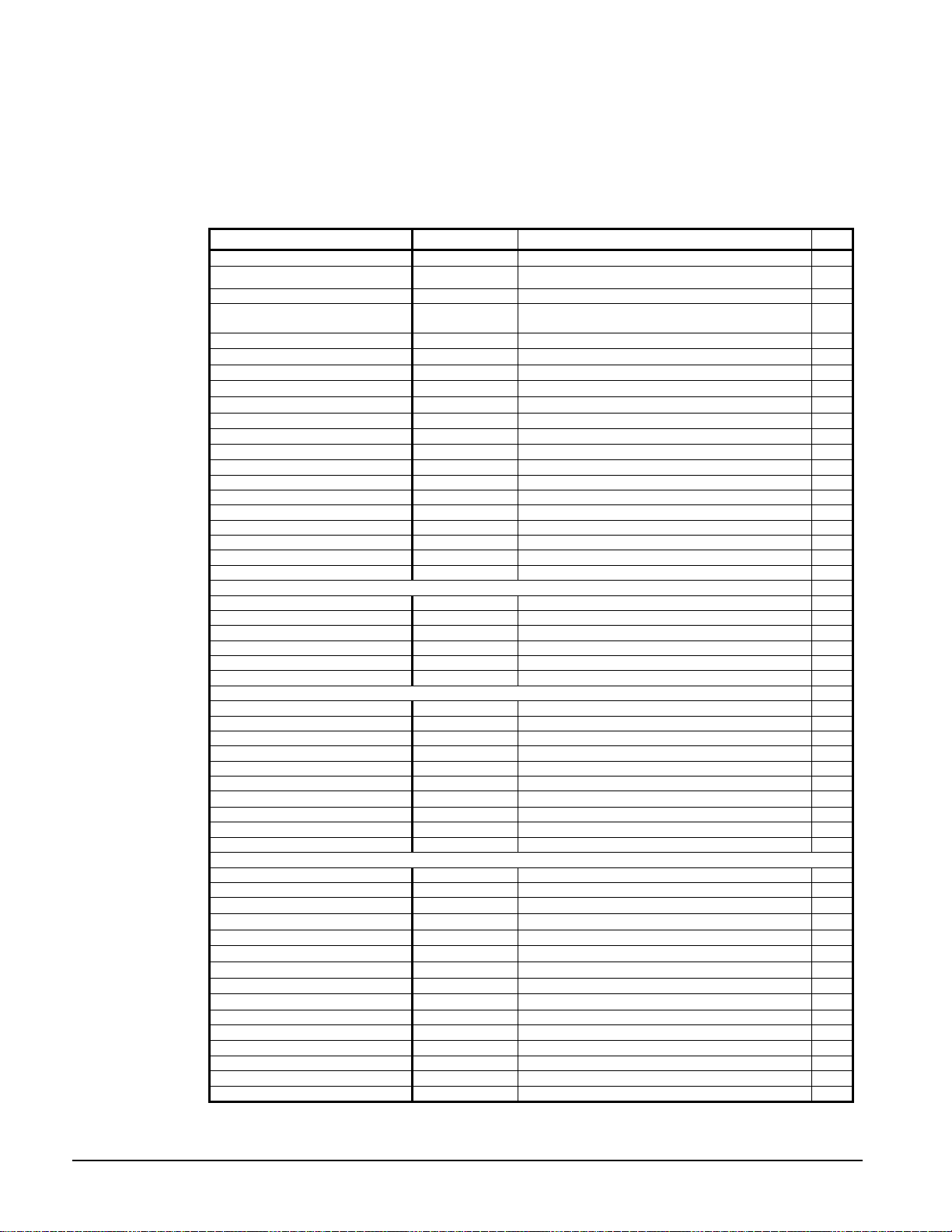
Table 11, Digital Inputs
# Description Type Signal Signal
1 Unit OFF Switch UT 0 VAC (Disable) 24 VAC (Enable)
2 Pump Down Switch #1 C1 0 VAC (Disable) 24 VAC (Enable)
3 Evaporator Water Flow Switch UT 0 VAC (No Flow) 24 VAC (Flow)
4 Open
5 Open
6 Pump Down Switch #2 C2 0 VAC (Disable) 24 VAC (Enable)
7 Open
8 Open
9 Phase Voltage Fault #1 (See Note 1) C1 0 VAC (Fault) 24 VAC (No Fault)
10 Phase Voltage Fault #2 (See Note 1) C2 0 VAC (Fault) 24 VAC (No Fault)
11 Ground Fault Prot. #1 (See Note 2 Below) C1 0 VAC (Fault) 24 VAC (No Fault)
12 Ground Fault Prot. #2 (See Note 2 Below) C2 0 VAC (Fault) 24 VAC (No Fault)
13 Remote Start/Stop UT 0 VAC (Disable) 24 VAC (Enable)
14 Open
15 Mechanical High Pressure/Motor Protect
Circuit 1
16 Mechanical High Pressure/Motor Protect
Circuit 2
17 Ice Mode Switch UT 0 VAC (Cool) 24 VAC (Ice)
18 Open
NOTES:
1. See Safety Alarms Table for “Phase Voltage Protection”. Units with single point electrical connection
will have one PVM with Inputs 9 and 10 wired together. Units with multiple point connection will
have two PVM’s with Input 9 for Electrical Circuit #1 and Input 10 for Electrical Circuit #2.
C2 0 VAC (Fault) 24 VAC (No Fault)
C2 0 VAC (Fault) 24 VAC (No Fault)
2. See Safety Alarms
Table 14 for “Ground Fault Protection”. Units with single point electrical
connection will have one GFP with Inputs 11 and 12 wired together. Units with multiple point
connection will have two GFP’s with Input 11 for Electrical Circuit #1 and Input 12 for Electrical
Circuit #2.
Table 12, Digital Outputs
No. Description Type Load Output OFF Output ON
1 Alarm C1,C2,UT Alarm Indicator Alarm OFF Alarm ON
2 Evaporator Water Pump UT Pump Contactor Pump OFF Pump ON
3 Condenser Fan #1 C1 Fan Contactor Fan OFF Fan ON
Motor Control Relay #1 =
4
Compr#1
Motor Control Relay #3 =
5
Compr#3
Motor Control Relay #5 =
6
Compr#5
7 Liquid Line #1 C1 Solenoid Cooling OFF Cooling ON
8 Condenser Fan #2 C2 Fan Contactor Fan OFF Fan ON
Motor Control Relay #2 =
9
Compr#2
Motor Control Relay #4 =
10
Compr#4
Motor Control Relay #6 =
11
Compr#6
12 Liquid Line #2 C2 Solenoid Cooling OFF Cooling ON
13 Condenser Fan #3 C1 Fan Contactor Fan OFF Fan ON
14 Hot Gas Bypass #1 C1 Solenoid Cooling OFF Cooling ON
15 Hot Gas Bypass #2 C2 Solenoid Cooling OFF Cooling ON
16 Condenser Fan #4 C2 Fan Contactor Fan OFF Fan ON
Condenser Fan #5 ( on 8
17
Fans Only)
Condenser Fan #6 ( on 8
18
Fans Only)
C1 Starter Compressor OFF Compressor ON
C1 Starter Compressor OFF Compressor ON
C1 Starter Compressor OFF Compressor ON
C2 Starter Compressor OFF Compressor ON
C2 Starter Compressor OFF Compressor ON
C2 Starter Compressor OFF Compressor ON
C1 Fan Contactor Fan OFF Fan ON
C2 Fan Contactor Fan OFF Fan ON
OM AGZ-1 AGZ 026B through 130B 17
Page 18
Setpoints
The setpoints shown in Table 13 are retained by battery-back-up and remembered
during power off, are factory set to the Default value, and can be adjusted within the
values shown in Range.
The PW (password) column indicates the password. Passwords are as follows:
O = Operator =0100 M = Manager=2001
Table 13, Setpoints
Description Default Range PW
Unit Enable OFF OFF, ON O
Unit Mode COOL COOL, COOL w/Glycol, ICE w/Glycol, TEST O
Control source DIGITAL IN KEYPAD, BAS, DIGITAL INPUT O
Available Modes COOL
Cool LWT O
Ice LWT O
Evap Delta T O
Startup Delta T O
Stop Delta T O
Max Pulldown Rate M
Evap Recirculate Timer 30 15 to 300 sec M
Low Ambient Lockout M
Demand Limit No No,Yes M
* Refrigerant Select None R22, R407c -* Multipoint Power No No,Yes M
Ice Time Delay 12 1 to 23 hrs.
Clear Ice Delay No No, Yes
Protocol Modbus BACnet, LonWorks, Modbus M
Ident number (Modbus only) 001 001-999 M
Baud rate (Modbus only) 9600 1200,2400,4800,9600,19200 M
Compressor
* Number of Compressors 4 4,6 M
Stage Up Delay 240 90 to 480 sec M
Stage Down Delay 30 20 to 60 sec M
Start-Start 15 min 10 to 60 min M
Stop-Start 5 min 3 to 20 min M
Clear Cycle Timers No No,Yes M
Alarms
Low Evap Pressure-Hold, R22 59 psi Glycol =31 to 65 psi Cool=55 to 65 psi M
Low Evap Pressure-Hold,R407c 60 psi Glycol =26 to 75 psi Cool=58 to 75 psi M
Low Evap Pressure-Unload,R22 58 psi Glycol =31 to 65 psi Cool=55 to 65 psi M
Low Evap Pressure-Unload,R407 59 psi Glycol =26 to 75 psi Cool=58 to 75 psi M
High Condenser Stage Down 370 psi 365 to 380 psi M
High Condenser Pressure 385 psi 385 to 390 psi M
Evaporator Water Freeze M
* Phase Voltage Protection No No,Yes M
* Ground Fault Protection No No,Yes M
Evap Flow Proof 3 sec 1 to 10 sec A
Condenser Fans
VFD Enable No No,Yes M
* Number of Fans 4 4,6,8 M
Stage Down 2 Deadband 6 to 10 F M
VFD Max Speed 100% 90 to 110% M
VFD Min Speed 25% 25 to 60% M
Sat Condenser Temp Target 100 M
Forced Fan 1 1 1 to # Fans Per Circuit M
Forced Fan 2 2 1 to # Fans Per Circuit M
Forced Fan 3 3 1 to # Fans Per Circuit M
(*) These items are factory set prior to shipment.
44. 0°F 20.0(40.0) to 60.0 °F
40. 0°F 20.0 to 40.0 °F
10. 0°F 6.0 to 16.0 °F
10.0°F 1.0 to 15.0 °F
0.5°F 0.5 to 3.0°F
1.0°F 0.2 to 5.0 °F
35 °F –2 to 70°F
38.0 °F 18(37) to 42°F
15°F
10°F
10°F
15°F
15°F
10°F
10°F
COOL, COOL w/GLYCOL, COOL/ICE
w/GLYCOL, ICE w/GLYCOL. TEST
15 to 25oF Stage Up 2 Deadband M
10 to 15oF Stage Up 3 Deadband M
10 to 15oF Stage Up 4 Deadband M
15 to 20oF Stage Down 0 Deadband M
10 to 15oF Stage Down 1 Deadband M
6 to 10oF Stage Down 3 Deadband M
90 to 120°F
M
18 AGZ 026B through 130B OM AGZ-1
Page 19

Automatic Adjusted Ranges
The following are setpoints that will be limited based on the option selected.
Evaporator Leaving Water Temperature
Mode Range
Unit Mode = Cool
Unit Mode = Cool w/Glycol
40 to 60°F
20 to 60°F
Evaporator Freeze Temperature
Mode Range
Unit Mode = Cool
Unit Mode = Cool w/Glycol,
Ice w/Glycol
37 to 42°F
18 to 42°F
Low Evaporator Pressure Hold and Unload
Mode Range
Unit Mode = Cool 55 to 65 Psig
Unit Mode = Cool w/Glycol,
Ice w/Glycol
31 to 65 Psig
Low Ambient Lockout Temperature
VFD Range
VFD = N
VFD = Y
35 – 60°F
-2 – 60°F
Forced Fan 1,2,3
Number of Fans Range
4 1 – 2 fans
6 1 – 3 fans
8 1 – 4 fans
Shutdown Alarms
Shutdown alarms (also know as “Stop Alarms” or “Safeties”) execute rapid compressor
shutdown and require manual reset. They are also logged in the Alarm Log.
The following table identifies each equipment protection alarm, gives the condition that
causes the alarm to occur, and states the action taken because of the alarm. If the alarm
is auto-clearing, the reset condition is also shown. Otherwise, the alarm is manually
reset, requiring the operator to clear the alarm.
OM AGZ-1 AGZ 026B through 130B 19
Page 20

Table 14, Shutdown Alarms
Description Occurs When:
No Evaporator Water Flow
Low Evaporator Pressure
High Condenser Pressure Condenser Press > High Condenser Pressure SP
Mechanical High Condenser
Pressure/Motor Protect
Phase Voltage Protection (opt.)
Ground Fault Protection (opt.)
Re-Start Fault Re-Start = Third Time Manual
Evap. Freeze Protect
Leaving Evap. Water Temp.
Sensor Fault
Evaporator Pressure Sensor
Fault
Condenser Pressure Sensor
Fault
Outside Ambient Temp. Sensor
Fault
Evap Pump State = RUN AND Evap Flow Digital
Input = No Flow for time > Evap Flow Proof SP
Evaporator Press < Low Evap Pressure SP for time
> Low Evap Pressure Delay SP
Digital Input = Off Rapid Stop
On Power Up: Delay 150 Sec. before checking
If Phase Voltage Protection = Y, Then Rapid Stop
Digital Input Off= Phase/Voltage Problem
If Phase Voltage Protection = Y, Then Rapid Stop
Digital Input Off= Phase/Voltage Problem
Evap LWT < Evaporator Freeze SP AND Unit state
= enable
Sensor shorted or open
Sensor shorted or open
Sensor shorted or open
Sensor shorted or open
Action
Taken
Rapid Stop
Unit
Rapid Stop
Circuit
Rapid Stop
Circuit
Circuit
Circuit
Circuit
Rapid Stop
Circuit
Rapid Stop
Unit
Normal Stop
Unit
Rapid Stop
Circuit
Rapid Stop
Circuit
Normal Stop
Unit
Reset
Manual
Manual
Manual
Manual
Phase/Voltage
Input returns to
normal
Manual
Manual
Manual
Manual
Manual
Manual
Events (Limit Alarms)
The following events limit the operation of the chiller in some way, as described in the Action
Taken column. These events are auto-clearing based on reaching the conditions in the reset
column.
Table 15, Events, Limit Alarms
Description Occurs When: Action Taken Reset
Condenser Pressure Stage
Down
Low Ambient Lockout Any compressor is running AND Outside
Low Evaporator Pressure –
Hold
Low Evaporator Pressure –
Unload
Failed Pumpdown Circuit fails to reach the setpoint Shut off circuit Not applicable
NOTES:
1. Low and high pressure events are disabled in the ICE mode.
Pressure > High Condenser Stage Down
Setpoint
Ambient < Low Amb Lockout SP
Pressure < Low Evap Pressure–Hold
Setpoint
Pressure < Low Evap Pressure–Unload
Setpoint
Shutoff Condenser Press drops
Stage #2
Shutoff Stages #1
& #2
Hold @ Evap Press rises above
Stage 1
Shutoff Evap Press rises above
Stage 2
below (SP – 100psi)
Outside Ambient > Low
Amb Lockout, (SP + 5ºF)
(SP + 8psi)
(SP + 10 psi)
Logging
When an alarm or event occurs, the description, date, and time are stored in the active alarm
buffer and can be viewed on the Alarm Active screens or on the Alarm Log or Event Log
screens. The active alarm buffers hold a record of all current alarms. The active alarms can be
cleared by pressing the Enter key when the end of the list has been reached by scrolling.
A password is NOT required to clear active alarms at the unit controller. The cause for an alarm
must be remedied before clearing the alarm. If the user attempts to clear an alarm while the
alarm condition still exists, a new alarm will be generated immediately.
Separate alarm and event logs store the last 25 alarms and events respectively. When an alarm
or event occurs, it is put into the first slot in the log, and all others are moved down one,
dropping the last entry.
If the alarm is a circuit alarm, then the circuit state, refrigerant pressures and temperatures, and
number of fans on are also stored. The parameters may be accessed by scrolling the last line on
the alarm log screen (similar to a setpoint).
20 AGZ 026B through 130B OM AGZ-1
Page 21

Control Logic
Unit Enable
Enabling and disabling the chiller is controlled by the Unit Enable Setpoint, with
options of OFF and ON. This setpoint can be altered by the Unit Off Input, Digital
Input, keypad entry, or BAS request. The Control Source setpoint determines which
source can change the Unit Enable setpoint with options of DIGITAL INPUT,
KEYPAD, or BAS.
Changing the Unit Enable Setpoint can be accomplished according to the following
table.
Table 16, Unit Enable Conditions
Unit Off
Input
OFF x x x x OFF
x SWITCHES OFF x x OFF
ON SWITCHES ON x x ON
ON KEYPAD X OFF x OFF
ON KEYPAD X ON x ON
ON NETWORK x x OFF OFF
ON NETWORK OFF x x OFF
ON NETWORK ON x ON ON
NOTE: An “x” indicates that the value is ignored
Unit Mode Selection
The overall operating mode of the chiller is set by the Unit Mode Setpoint with options
of COOL, COOL w/Glycol, ICE w/Glycol, and TEST. This mode setting can be altered
by the keypad, BAS, and Mode input. Changes to the Unit Mode Setpoint are
controlled by two additional setpoints:
Control Source
Setpoint
Remote Input Keypad Entry BAS Request Enable
Available Modes Setpoint: Determines the operational modes available at any time
•
with options of COOL, COOL w/Glycol, COOL/ICE w/Glycol, and TEST.
•
Control Source Setpoint: Determines the source that can change the Unit Mode
Setpoint with options of KEYPAD, NETWORK, or SWITCHES.
When the Control source is set to KEYPAD, the Unit Mode stays at its previous setting
until changed by the operator. When the Control source is set to BAS, the most recent
BAS mode request goes into effect, even if it changed while the Control source was set
to KEYPAD or DIGITAL INPUTS.
Changing the Unit Mode Setpoint can be accomplished according to the following
table.
Table 17, Unit Mode Selection
Control Source
Setpoint
x x x x
x x x x COOL w/Glycol COOL w/Glycol
SWITCHES OFF x x COOL/ICE w/Glycol COOL w/Glycol
SWITCHES ON x x COOL/ICE w/Glycol ICE w/Glycol
KEYPAD x COOL w/Glycol x COOL/ICE w/Glycol COOL w/Glycol
KEYPAD x ICE w/Glycol x COOL/ICE w/Glycol ICE w/Glycol
NETWORK x x COOL COOL/ICE w/Glycol COOL w/Glycol
NETWORK x x ICE COOL/ICE w/Glycol ICE w/Glycol
x x x x ICE w/Glycol ICE w/Glycol
x x x x TEST TEST
NOTE: An “x” indicates that the value is ignored.
Mode
Input
Keypad Entry Unit Mode
BAS
Request
Available Modes
Setpoint
COOL
COOL
OM AGZ-1 AGZ 026B through 130B 21
Page 22

Unit Test Mode
N
N
The unit test mode allows manual testing of controller outputs. Entering this mode
requires the following conditions.
Unit OFF input = OFF (i.e., entire chiller is shut down).
Manager password active.
Available Unit Mode setpoint = TEST
A test menu can then be selected to allow activation of the outputs. It is possible to
switch each digital output ON or OFF and set the analog outputs to any value.
Chilled Water Pump Control
Operation of the evaporator pump is controlled by the state-transition diagram shown
below.
TEST: Unit State=OFF &
All Comp State=OFF &
O Evap water freeze condition
Power ON
RUN
OFF
TEST: Unit State = AUTO AND
At least one circuit is enabled for start
OR
Evap water freeze condition
TEST: Unit State=OFF &
All Comp State=OFF &
O Evap water freeze condition
START
TEST: Flow OK for
Evap Recirc Time
Compressor Control
Compressor Sequencing
This section defines which compressor is the next one to start or stop. The next section
defines when
Compressor sequencing is based primarily on compressor run-hours and starts.
Compressors that have less starts will start before those with more starts. Compressors
that have more run-hours will shut off before those with less run-hours. In the event of a
tie on number of starts, the lower numbered compressor starts first. In the event of a tie
on run-hours, the lower numbered compressor shuts off first.
If possible, the number of running compressors on each circuit will be balanced. If a
circuit is unavailable for any reason, the other circuit is allowed to stage on all
compressors.
22 AGZ 026B through 130B OM AGZ-1
the start, or stop, is to occur.
Page 23

Required Parameters
• Number of starts for all compressors
• Number of run-hours for all compressors
• Status of all compressors (Available/Unavailable)
• Compressor number
Compressor Start/Stop Timing-Cool Mode
This section defines when a compressor is to start, or stop, and the scenario for doing
so.
Initial Start Time Delay
There is a 150-second delay after power-up before any compressor is allowed to start.
This is required since the motor overloads and the Manual High Pressure (MHP) are
ignored during this time.
Required Parameters
1. Start Delta setpoint.
2. Max Pulldown Rate setpoint
3. Evap Delta T setpoint
4. Number of Compressors/Circuit setpoint
5. LWT error
6. LWT Slope
7. Number of compressors running
8. Interstage timer status
Stage Up
For 2 compressors/circuit:
Control band = Evap Delta T x .25
For 3 compressors/circuit:
Control band = Evap Delta T x .17
IF [LWT Error > Startup_Delta_T_SP + 0.5(Control band)
AND No Compressors Running
AND Stage Up Timer Expired]
THEN Stage_Up_Now = YES
ELSE IF
[LWT Error > 0.5(Control band) AND LWT Slope <= Max Pulldown setpoint
AND Stage Up Timer Expired]
THEN Stage_Up_Now = YES
Stage Down
IF [LWT Error < -0.5(Control band)
AND Stage Down Timer Expires]
THEN Stage_Down_Now = YES
OM AGZ-1 AGZ 026B through 130B 23
Page 24

Compressor Start/Stop Timing – Ice Mode
This section defines when a compressor is to start, or stop, and the scenario for doing
so.
Required Parameters
Start Delta setpoint
Evap Delta T setpoint
Number of Compressors/Circuit setpoint
LWT error
Number of compressors running
Interstage timer status
Ice timer status (12 hours between starts)
Stage Up
For 2 compressors/circuit:
Control band = Evap Delta T x .3
For 3 compressors/circuit:
Control band = Evap Delta T x .2
IF
[LWT Error > Startup_Delta_T_SP + 0.5(Control band)
AND Number Comps Running = 0
AND Ice Timer Expired]
THEN Stage_Up_Now = YES
ELSE IF
[LWT Error > 0
AND Number Comps Running > 0
AND Stage Up Timer Expired]
THEN Stage_Up_Now = YES
Stage Down
IF LWT Error < 0
THEN Stage_Down_Now = YES
Leaving Water Reset
The leaving water reset input uses a 4-to-20mA signal to reset the leaving water
setpoint to a higher value. The adjustment varies linearly from 0 degrees F to 10
degrees F, with a reset of 0 for a 4mA signal and a reset of 10 for a 20mA signal.
At all times, the active leaving water setpoint is limited to a maximum of 60°F. Th e
reset remains proportional within the 10 degree band, but the setpoint will simply stop
resetting when it reaches the maximum.
24 AGZ 026B through 130B OM AGZ-1
Page 25

Circuit Capacity Overrides – Limits of Operation
The following conditions override the automatic capacity control when the chiller is in
COOL mode or ICE mode. These overrides keep a circuit from entering a condition in
which it is not designed to run.
Low Evaporator Pressure
If a circuit is running, and the evaporator pressure drops below the Low Evaporator
Pressure-Hold setpoint, no more compressors will be allowed to start on that circuit.
This limit is active until the evaporator pressure reaches the hold setpoint plus 8 psi.
If a circuit is running with two or three compressors on, and the evaporator pressure
drops below the Low Evaporator Pressure-Unload setpoint, the circuit will begin
reducing capacity. If two compressors are running, one of the running compressors will
be stopped. If three compressors are running, then one compressor will be stopped
initially. Ten seconds later, if the pressure has not risen above the unload setpoint,
another compressor will be stopped. The last compressor on a circuit will not stop due
to the unload condition.
High Condenser Pressure
If the discharge pressure rises above the High Condenser Pressure Unload setpoint, and
more than one compressor on the circuit is running, the circuit will stage down. One
compressor will shutdown as soon as the pressure rises above the unload setpoint, and
if two remain running, then one more will shut down 10 seconds later, if the pressure is
still above the unload setpoint. No stage up will be allowed on the circuit until the
condenser pressure drops to the unload setpoint, less 100 psi, and the outdoor ambient
temperature drops 5 degrees F.
Low Ambient Lockout
If the OAT drops below the low ambient lockout setpoint, then all running circuits will
do a normal stop. Once the lockout has been triggered, no compressors will start until
the OAT rises to the lockout setpoint plus 5 degrees F.
If the unit is shutdown because the outside air temperature is to low (Low OAT
Lockout) then the evaporator pump will be shut down after all active circuits have been
pumped down.
The evaporator pump will remain off as long is the chiller is locked out on a low
ambient air temperature condition.
High Ambient Limit
On units not configured with multi-point power connections, the maximum load amps
could be exceeded at high ambient temperatures. If all circuit 1 compressors are
running or all but one compressor on circuit 1, power connection is single point, and the
OAT is greater than 116°F, circuit 2 is limited to running all but one compressor. The
circuit 2 status will indicate if this is the case. This action will allow the unit to operate
at higher temperatures than 116°F.
Unit Capacity Overrides
The following conditions override the automatic capacity control when the chiller is in
COOL mode only.
Demand Limit
The maximum unit capacity can be limited by a 4-to-20 mA signal on the Demand
Limit analog input. This function is only enabled if the Demand Limit setpoint is set to
ON. The maximum unit capacity stage is determined as shown in the following graphs:
OM AGZ-1 AGZ 026B through 130B 25
Page 26

Max
Stage
Limit Signal vs. Max Stage
(with 4 compressors)
4
3
2
1
Max
Stage
0.0 25.0 50.0 100.075.0
6
5
4
3
2
1
0
0 16.7 66.7 83.350.0
Limit Signal (%)
Limit Signal vs. Max Stage
(with 6 compressors)
33.3 100.0
Limit Signal (%)
BAS Limit
The maximum unit capacity can be limited by a BAS signal. This function is only
enabled if the unit control source is set to network. The maximum unit capacity stage is
based on the BAS limit value received from the BAS, and is determined as shown in the
graphs in the previous section.
Maximum LWT Rate
The maximum rate at which the leaving water temperature can drop is limited at all
times by the Maximum Rate setpoint. If the rate exceeds this setpoint, no more
compressors will be started until the pulldown rate is less than the setpoint.
Pumpdown
When a circuit reaches a condition where it needs to shut down normally, a pumpdown
cycle will be performed. All but the lowest numbered running compressor will shut off.
During pumpdown, the hot gas bypass and liquid line valves are closed, while a
compressor continues to run. The pumpdown is complete when the evaporator pressure
is less than the low evaporator pressure unload setpoint, less 15 psi, or the circuit has
been in the pumpdown state for 60 seconds.
Condenser Fan Control
Stage Up Compensation
In order to create a smoother transition when another fan is staged on, the VFD
compensates by slowing down initially. This is accomplished by adding the new fan
stage up deadband to the VFD target. The higher target causes the VFD logic to
decrease fan speed. Then, every 10 seconds, 0.5 degree F is subtracted from the VFD
target until it is equal to the saturated condenser temperature target setpoint. This will
allow the VFD to slowly bring the saturated condenser temperature back down.
26 AGZ 026B through 130B OM AGZ-1
Page 27

Fantrol
Condenser Fans Staging is based on condenser pressure as selected by Fan Stage On &
Off setpoints. Fans 1, 3, 5, and 7 are for circuit 1, and fans 2, 4, 6, and 8 are for circuit
2. Fans 1 and 2 start with the first compressor on the respective circuit when the
ambient temperature is greater than 75°F. Below 75°F, these fans start when the
condenser pressure gets up to the stage on setpoint. The compressor must be running in
order to run any fans.
Fan Stages
There are 2, 3, or 4 fans available per circuit. On 8 fan units, fans 5/7 and 6/8 are
controlled by one contactor for each pair, using virtual stages to allow a difference of
only one fan between stages. See the tables below:
4 and 6 Fan Units
Stage (3-Fan) Fans On Cir. 1 Fans On Cir. 2
1 1 2
2 1,3 2,4
3 1,3,5 2,4,6
8 Fan Units
Stage (2&4-Fan) Fans On Cir 1 Fans On Cir. 2
1 1 2
2 1,3 2,4
3 1,5,7 2,6,8
4 1,3,5,7 2,4,6,8
Normal Operation - Staging Up
At startup, the first fan will start when the saturated condenser temperature rises above
the target. After this, the stage-up deadbands apply.
When the saturated condenser temperature is above the Target + the active deadband, a
Stage Up error is accumulated.
Stage Up Error Step = Saturated Condenser Refrigerant temperature – (Target + Stage
Up dead band)
The Stage Up Error Step is added to Stage Up Accumulator once every Stage Up Error
Delay seconds. When Stage Up Error Accumulator is greater than the Stage Up Error
Setpoint another stage is started.
When a stage-up occurs or the saturated condenser temperature falls back within the
Stage Up dead band, the Stage Up Accumulator is reset to zero.
Normal Operation - Staging Down
There are four Stage Down dead bands, one for each stage.
When the saturated condenser refrigerant temperature is below the Target – the active
deadband, a Stage Down error is accumulated.
Stage Down Error Step = (Target − Stage Down dead band) − Saturated Condenser
Refrigerant temperature
The Stage Down Error Step is added to Stage Down Accumulator once every Stage
Down Error Delay seconds. When the Stage Down Error Accumulator is greater than
the Stage Down Error Setpoint, another stage of condenser fans turns off. The last
stage on will not shut off until the circuit is in an off state.
OM AGZ-1 AGZ 026B through 130B 27
Page 28

When a stage down occurs, or the saturated temperature rises back within the Stage Down dead
band, the Stage Down Error Accumulator is reset to zero.
Forced Fan Stage At Start
Fans may be started simultaneously with the compressor based on outdoor ambient temperature.
When the compressor starts, a FanTrol stage is forced based on the following table.
Table 18, Forced Fan Staging
,
> 75 oF Forced Fan 1 SP
> 90 oF Forced Fan 2 SP
> 105 oF Forced Fan 3 SP
FanTrol Stage At Start
Up to four fans may be forced on when the compressor starts. If the unit has the Optional Low
Ambient VFD option, then only three fans can start with the compressor, and the VFD will start
normally when the saturated condenser temperature is higher than the target.
After forcing fans on, the saturated condenser temperature may temporarily stay below the
target by some amount. In order to keep these fans from staging off, no stage down error can be
accumulated until either the OAT drops below 75
o
F, or the saturated condenser temperature
goes above the target.
Low Ambient Startup
A new low ambient start logic has been implemented in this version. A low ambient start takes
place if the saturated condenser temperature is less than 85.0°F when the first compressor starts.
The low ambient start is active for a time defined by the Low OAT Start Timer set point. This
set point is found on screen four in the alarm set points menus.
During the low ambient start, the freezestat logic for the low pressure stop alarm and the low
pressure events are disabled. The low pressure stop alarm can still be triggered if the evaporator
pressure drops below 5.0 psi at any time while the circuit is in the ‘Run’ state. Also, during the
low ambient start the second compressor is not allowed to start.
The evaporator pressure is checked at the end of the low ambient start timeframe. If the pressure
is less than the low pressure unload set point, then the low ambient start is not successful and
the compressor will shut off. This will not be a manual reset alarm until three consecutive
attempts have failed. The circuit alarm triggered after the third failed attempt is a Low OAT
Restart fault.
Low Ambient Stage Up
In colder ambient conditions, the evaporator pressure may take several minutes to rise and
stabilize after the first compressor starts. Starting the second compressor too soon will cause a
low-pressure situation that usually cannot be recovered from. To avoid this problem the
following occurs:
• The Interstage Up Time Delay set point range is 90 to 480 seconds.
• The default value of the Interstage Up Time Delay set point is 240 seconds.
When a second compressor stages on, there is a temporary drop in evaporator pressure until the
TXV has a chance to react. This condition is especially evident in colder conditions. In order to
avoid short cycling the second compressor just after it starts, the following logic exists:
• The low evaporator pressure events are disabled temporarily after the second stage starts up.
The delay time is 30 seconds.
• Normal protection against low evaporator pressure conditions resumes after the 30-second
delay timer expires
28 AGZ 026B through 130B OM AGZ-1
Page 29

Evaporator Pressure Control
Low Evaporator Pressure Protection
• The minimum time allowed to run in low evaporator pressure conditions with the
freezestat logic has been changed from 10 to 20 seconds.
• The absolute minimum pressure limit logic has been changed to trip the low-pressure
alarm only when the circuit state is in a Run state.
Low Evaporator Pressure Hold Events
• The Low Evaporator Pressure Hold can trigger with two compressors running. With this
logic, the Hold event can be logged and if the evaporator pressure continues to drop
enough to trip the Low Evaporator Pressure Unload event, the Unload event will be
added to the Event log.
• The Low Evaporator Pressure Hold event reset logic will clear the Hold event at 5.0 psi
above the Hold set point.
• The logic will allow the Low Evaporator Pressure Hold events to occur when the Unit is
in the Ice mode.
Low Evaporator Pressure Unload Events
• The Low Evaporator Pressure Unload events clear with the Low Evaporator Pressure
Hold events.
• The logic allows the Low Evaporator Pressure Unload events to occur when the Unit is
in the Ice mode
Optional Low Ambient VFD
Low ambient air temperature control is accomplished by using the Optional Low Ambient VFD
to control the speed of the first fan on each circuit. This VFD control uses a proportional
integral function to drive the saturated condenser temperature to a target value by changing the
fan speed. The target value is normally the same as the saturated condenser temperature target
setpoint.
The fan VFD always starts when the saturated condenser temperature rises higher than the
target.
What is an Inverter?
The term inverter and variable-frequency drive are related and somewhat interchangeable. An
electronic motor drive, for an AC motor, controls the motor’s speed by varying the frequency of
the power sent to the motor.
An inverter, in general, is a device that converts DC power to AC power. The figure below
shows how the variable-frequency drive employs an internal inverter. The drive first converts
incoming AC power to DC through a rectifier bridge, creating an internal DC bus voltage. Then
the inverter circuit converts the DC back to AC again to power the motor. The special inverter
can vary its output frequency and voltage according to the desired motor speed.
OM AGZ-1 AGZ 026B through 130B 29
Page 30

Inverter Output to the Motor
The AC motor must be connected only to the inverter’s output
terminals. The output terminals are uniquely labeled (to
differentiate them from the input terminals) with the
designations U/T1, V/T2, and W/T3. This corresponds to
typical motor lead connection designations T1, T2, and T3. The
consequence of swapping any two of the three connections is
the reversal of the motor direction. This must not be done. In
applications where reversed rotation could cause equipment
damage or personnel injury, be sure to verify direction of
rotation before attempting full-speed operation. For safety to
personnel, the motor chassis ground must be connected to the
ground connection at the bottom of the inverter housing.
Notice the three connections to the motor do not include one marked “Neutral” or “Return.” The
motor represents a balanced “Y” impedance to the inverter, so there is no need for a separate
return. In other words, each of the three “Hot” connections serves also as a return for the other
connections, because of their phase relationship.
Do not to switch off power to the inverter while the motor is running (unless it is an emergency
stop). Also, do not install or use disconnect switches in the wiring from the inverter to the motor
(except thermal disconnect).
Inverter Front Panel Keypad
The CR100 Series inverter front keypad contains all the elements for both monitoring and
programming parameters. The keypad layout is pictured below. The fan VFD is programmed in
the factory before shipment and no field programming is required.
Key and Indicator Legend
Run/Stop LED - ON when the inverter output is ON and the motor is developing torque (Run
Mode), and OFF when the inverter output is OFF (Stop Mode).
Program/Monitor LED - This LED is ON when the inverter is ready for parameter editing
(Program Mode). It is OFF when the parameter display is monitoring data (Monitor Mode).
Run Key Enable LED - is ON when the inverter is ready to respond to the Run key, OFF when
the Run key is disabled.
Run Key - Press this key to run the motor (the Run Enable LED must be ON first). Parameter
F_04, Keypad Run Key Routing, determines whether the Run key generates a Run FWD or Run
REV command.
Stop/Reset Key - Press this key to stop the motor when it is running (uses the programmed
deceleration rate). This key will also reset an alarm that has tripped.
30 AGZ 026B through 130B OM AGZ-1
Page 31

Potentiometer -Allows an operator to directly set the motor speed when the potentiometer is
enabled for output frequency control.
Potentiometer Enable LED - ON when the potentiometer is enabled for value entry.
Parameter Display - A 4-digit, 7-segment display for parameters and function codes.
Display Units, Hertz/Amperes - One of these LEDs will be ON to indicate the units associated
with the parameter display.
Power LED - This LED is ON when the power input to the inverter is ON.
Function Key - This key is used to navigate through the lists of parameters and functions for
setting and monitoring parameter values.
Up/Down (
1
,
2
) Keys - Use these keys alternately to move up or down the lists of
parameter and functions shown in the display, and increment/decrement values.
Sto re ( ) Key - When the unit is in Program Mode and you have edited a parameter value,
press the Store key to write the new value to the EEPROM.
Keypad Navigational Map
The CR100 Series inverter front keypad contains all the elements for both monitoring and
programming parameters. The diagram below shows the basic navigational map of parameters
and functions.
OM AGZ-1 AGZ 026B through 130B 31
Page 32

NOTE: The inverter 7-segment display shows lower case “b” and “d,” meaning the same as the
upper case letters “B” and “D” used in this manual (for uniformity “A to F”).
NOTE: The Store Key saves the edited parameter (shown in the display) to the EEPROM in the
inverter, regardless of the programming device. Upload and download of parameters is
accomplished through a separate command—do not confuse Store with Download or Upload.
Troubleshooting Tips
The table below lists typical symptoms and the corresponding solution(s).
Symptom
Condition
The inverter
outputs [U],
[V], [W] are not
supplying
voltage.
The
motor
will not
run.
Inverter
outputs [U],
[V], [W] are
supplying
voltage.
The optional
remote
operator is
used (SRW).
The direction of the motor
is reversed.
The motor speed will not
reach the target
frequency (desired
speed).
Continued on next page.
•
•
• •
• • Is there an error code E X X displayed? Press the Func. key and determine the error
•
•
•
•
• • Is the RS (reset) function or FRS (free-run
• • Is the motor load too heavy? Reduce load, and test the motor
• • Are the operational settings between the
•
•
•
•
• •
• •
• •
Probable Cause Solution
Is the frequency command source A_01
parameter setting correct?
Is the Run command source A-02
parameter setting correct?
Is power being supplied to terminals [L1],
[L2], and [L3/N]? If so, the POWER lamp
should be ON.
Are the signals to the intelligent input
terminals correct?
Is the Run Command active?
Is the {FW] terminal (or [RV]) connected to
[P24] (via switch, etc.)
Has the frequency setting for F_01 been
set greater than zero?
Are the control circuit terminals [H], [O],
and [L] connected to the potentiometer?
stop) function ON?
remote operator and the inverter unit
correct?
[U/T1], [V/T2], and [W/T3] correct?
Is the phase sequence of the motor
forward or reverse with respect to [U/T1],
[V/T2], and [W/T3]?
Are the control terminals [FW] and [RW]
wired correctly?
Is parameter F_04 properly set?
If using the analog input, is the current or
voltage at [O] or [OI]?
Is the load too heavy? Reduce the load
Is the inverter internally limiting the output
frequency?
•
Make sure the parameter setting A-01 is
correct.
•
Make sure the parameter setting A-02 is
correct.
Check terminals [L1], [L2], and [L3/N], then
[U/T1], [V/T2], and [W/T3].
•
Turn ON the power supply or check fuses.
type. Eliminate the error cause, then clear the
error (Reset).
•
Verify the terminal functions for C_01 – C_05
are correct.
•
Turn ON Run Command enable.
Supply 24V to {FW] or [RV] terminal, if
•
configured.
•
Set the parameter for F_01 to a safe, non-zero
value.
•
If the potentiometer is the frequency setting
source, verify voltage at [O] > 0V.
Turn OFF the command(s).
independently.
Check the operator type setting.
• Are the connections of output terminals
Make connections according to the phase
sequence of the motor. In general:
FWD = U-V-W, and
REV = U-W-V.
•
Use terminal [FW] for forward, and [RV] for
reverse.
•
Set motor direction in F_04.
Reduce the load.
•
Heavy loads activate the overload restriction
feature (reduces output as needed).
Heavy loads activate the overload restriction
•
feature (reduces output as needed).
Check max frequency setting (A_04).
Check frequency upper limit setting (A_61).
•
32 AGZ 026B through 130B OM AGZ-1
Page 33

Symptom Condition Probable Cause Solution
The RPM of the motor does
not match the inverter output
frequency setting.
No
downloads
have
Inverter data is
not correct.
A parameter
will not change
after an edit
(reverts to old
setting).
occurred.
A download
to the
inverter was
attempted.
True for
certain
parameters.
True for all
parameters.
•
Is the maximum frequency setting A_04
correct?
•
Does the monitor function D_01 display
the expected output frequency?
• • Was power turned OFF after a
parameter edit but before pressing the
Store key?
• • Edits to data are permanently stores at
power down. Was the time from power
OFF to power ON less than six
seconds?
• • Was the power turned OFF within six
seconds after the display changed from
REMT to INV?
• • Is the inverter in Run Mode? Some
parameters cannot be edited during
Run Mode.
• • If you’re using the [SFT] intelligent input
(software lock function)⎯is the [SFT]
input ON?
•
Verify the V/f settings match motor
specification.
•
Make sure all scaling (such as A_11 to
A_14) is properly set.
Edit the data and press the Store key once.
Wait six seconds or more before turning
power OFF after editing data.
Copy data to the inverter again, and keep
power ON for six seconds or more after
copying.
Put inverter in Stop Mode (press the
Stop/reset key). Then edit the parameter.
Change the state of the SFT input, and
check the B_31 parameter (SFT mode).
Monitoring Trip Events, History. & Conditions
Fault Detection and Clearing
The microprocessor in the inverter detects a variety of fault
conditions and captures the event, recording it in a history
table. The inverter output turns OFF, or “trips” similar to the
way a circuit breaker trips due to an over-current condition.
Most faults occur when the motor is running (refer to the
diagram to the right). However, the inverter could have an
internal fault and trip in Stop Mode. In either case, you can
clear the fault by pressing the Stop/Reset key.
OM AGZ-1 AGZ 026B through 130B 33
Page 34

Error Codes
An error code will appear on the display automatically when a fault causes the inverter to trip. The
following table lists the cause associated with the error.
Error
Code
E01
E02
E03
E04
E05
E07
E08
E09
E11
E22
E12
E13
E14
E15
E21
E35
---U
Name Cause(s)
Over current event while at constant
speed
Over current event during deceleration
Over current event during acceleration
Over current event during
other conditions
Overload protection
Over voltage protection
EEPROM error
Under-voltage error
CPU error
External trip
USP
Ground fault
Input over-voltage
Inverter thermal trip
Thermistor
Under-voltage (brownout) with output
shutoff
The inverter output was short-circuited, or the motor shaft is locked or
has a heavy load. These conditions cause excessive current for the
inverter, so the inverter output is turned OFF.
The dual-voltage motor is wired incorrectly.
When a motor overload is detected by the electronic thermal function,
the inverter trips and turns OFF its output.
When the DC bus voltage exceeds a threshold, due to regenerative
energy from the motor.
When the built-in EEPROM memory has problems due to noise or
excessive temperature, the inverter trips and turns OFF its output to
the motor.
A decrease of internal DC bus voltage below a threshold results in a
control circuit fault This condition can also generate excessive motor
heat or cause low torque. The inverter trips and turns OFF its output.
A malfunction in the built-in CPU has occurred, so the inverter trips
and turns OFF its output to the motor.
A signal on an intelligent input terminal configured as EXT has
occurred. The inverter trips and turns OFF the output to the motor.
When the Unattended Start Protection (LJSP) is enabled, an error
occurred when power is applied while a Run signal is present. The
inverter trips and does not go into Run Mode until the error is cleared.
The inverter is protected by the detection of ground faults between the
inverter output and the motor during powerup tests. This feature
protects the inverter, and does not protect humans.
When the input voltage is higher than the specified value, it is detected
100 seconds after powerup and the inverter trips and turns OFF its
output.
When the inverter internal temperature is above the threshold, the
thermal sensor in the inverter module detects the excessive
temperature of the power devices and trips, turning the inverter output
OFF.
When a thermistor is connected to terminals {5} and [CM1] and the
inverter has sensed the temperature is too high, the inverter trips and
turns OFF the output.
Due to low input voltage, the inverter turns its output OFF and tries to
restart. If it fails to restart, then the alarm trips to record the undervoltage error event.
Note: If an EEPROM error (E08) occurs, be sure to confirm the parameter data values are still
correct. If the power is turned OFF while the [RS] (Reset) intelligent input terminal is ON, an
EEPROM error will occur when power is restored.
Trip History and Inverter Status
Always find the cause of the fault before clearing it. When a fault occurs, the inverter stores
important performance data at the moment of the fault. To access the data, use the monitor
functions (D_xx) and select D_08 for details about the present fault (E
past two trip events (E
n-1
) and E
n-2
) using the D_09 Trip History function.
The following Monitor Menu map shows how to access the error codes. When fault(s) exist, you
can review their details by first selecting the proper function: D_08 displays current trip data, and
D09 displays trip history.
34 AGZ 026B through 130B OM AGZ-1
n
), or the error code for the
Page 35

VFD Monthly and Yearly Inspection Chart
Item Inspected Check for ... Inspection Method Criteria
Ambient
environment
Overall
Main
circuit
Control
circuit
Display LEDs Legibility Visual All LED segments work
Major devices Visual & aural
Power supply
voltage
Ground Insulation Adequate resistance 5 Meg. Ohms or greater
Mounting No loose screws Torque wrench M4: 0.98 – 1.3 Nm
Components Overheating Thermal trip events No trip events
Housing Dirt, dust Visual Vacuum dust & dirt
Terminal block Secure connections
Smoothing
capacitor
Relay(s) Chattering Aural
Resistors Cracks or discoloring Visual
Cooling fan
Overall
Capacitor No leaks or deformation
Extreme Temperatures &
humidity
Abnormal noise &
vibration
Voltage tolerance
Leading, swelling
Noise
Dust
No order, discoloring,
corrosion
Frequency
Month Year
Thermometer, hygrometer
Visual No abnormalities
Power down, manually rotate Rotation must be smooth
Visual Vacuum to clean
Visual Undistorted appearance
Ambient temperature
between – 10 to 40°C, noncondensing
Stable environment for
electronic controls
Digital volt meter, measure
between inverter terminals
[L1], [L2], [L3}
Digital volt meter, GND to
terminals
Visual No abnormalities
Visual No abnormalities
200V class:
200 to 240V 50/60 Hz
400V class:
380 to 460V 50/60 Hz
M3: 0.5 – 0.6 Nm
M5: 1.5 – 2.0 Nm
Single click when switching
ON or OFF
Use Ohm meter to check
braking resistors
OM AGZ-1 AGZ 026B through 130B 35
Page 36

Important Messages
WARNING
WARNING HIGH VOLTAGE: Motor control equipment and electronic controllers
are connected to hazardous line voltages. When servicing drives and electronic
controllers, there may be exposed components with housings or protrusions at
or above line potential. Extreme care should be taken to protect against shock.
Stand on an insulating pad and make it a habit to use only one hand when
checking components. Always work with another person in case an emergency
occurs. Disconnect power before checking controllers or performing
maintenance. Be sure equipment is properly grounded. Wear safety glasses
whenever working on electronic controllers or rotating machinery.
WARNING
Wait at least five (5) minutes after turning OFF the input power supply before
performing maintenance or an inspection.
Otherwise, there is the danger of electric shock.
Introduction
This section lists the parameters for the CR100 series inverters and the values as programmed in the
factory.
Unit identification
Parameter Settings for Keypad Entry
Main Profile Parameters
“F” Group Parameters
Function
Code
F_01 Output Frequency Setting
F_02 Acceleration (1)
F_03 Deceleration (1)
F_04 Keypad Run Key Routing
Name
McQuay
Setting
0.0
10.0
10.0
00
36 AGZ 026B through 130B OM AGZ-1
Page 37

Standard Functions
“A” Group Parameters
Function
Code
A_01 Frequency source setting 01
A_02 Run command source setting 01
A_03 Base frequency setting 60.0
A_04 Maximum frequency setting
A_11 O-L input active range start frequency
A_12 O-L input active range end frequency
A_13 O-L input active range start voltage
A_14 O-L input active range end voltage
A_15 O-L input start frequency enable
A_16 External frequency filter time constant
A_20 Multi-speed 0 setting
A_21 Multi-speed 1 setting
A_22 Multi-speed 2 setting
A_23 Multi-speed 3 setting
A_24 Multi-speed 4 setting
A_25 Multi-speed 5 setting
A_26 Multi-speed 6 setting
A_27 Multi-speed 7 setting
A_28 Multi-speed 8 setting
A_29 Multi-speed 9 setting
A_30 Multi-speed 10 setting
A_31 Multi-speed 11 setting
A_32 Multi-speed 12 setting
A_33 Multi-speed 13 setting
A_34 Multi-speed 14 setting
A_35 Multi-speed 15 setting
A_38 Jog frequency setting
A_39 Jog stop mode
A_41 Torque boost method selection
A_42 Manual torque boost value
A_43
A_44 V/f characteristic curve selection
A_45 V/f gain setting
A_51 DC braking enable
A_52 DC braking frequency setting
Manual torque boost frequency
adjustment
Name
McQuay
Setting
60.0
0
0
0
100
01
8
0
0
0
0
0
0
0
0
0
0
0
0
0
0
0
0
1.0
00
00
11
10.0
00
100
00
0.5
“A” Group Parameters
Function
Code
A_53 DC braking wait time 0.0
A_54 DC braking force during deceleration 0
A_55
A_61 Frequency upper limit setting
A_62 Frequency lower limit setting
A_63,
A_65,
A_67
A_64-
A_66
A_68
A_71 PID Enable
A_72 PID proportional gain
A_73 PID integral time constant
A_74 PID derivative gain
A_75 PV scale conversion
A_76 PV source setting
A_81 AVR function select
A_82 AVR voltage select
A_92 Second acceleration time setting
A_93 Second deceleration time setting
A_94
A_95 Acc1 to Acc2 frequency transition point
A_96 Dec1 to Dec2 frequency transition point
A_97 Acceleration curve selection
A_98 Deceleration curve selection
DC braking time during deceleration
Jump (center) frequency setting
Jump (hysteresis) frequency width
setting
Select method to switch to second
accel/decel profile
Name
McQuay
Setting
0.0
0.0
0.0
0.0
0.5
00
1.0
1.0
0.0
1.00
00
00
230/460
15.0
15.0
00
0.0
0.0
00
00
OM AGZ-1 AGZ 026B through 130B 37
Page 38

Fine Tuning Functions
“B” Group Parameters
Function
Code
B_01 Selection of automatic restart 00
B_02
B_03 Retry wait time before motor restart 1.0
B_12 Level of electronic thermal setting
B_13 Electronic thermal characteristic
B_21 Overload restriction operation mode
B_22 Overload restriction setting
B_23 Deceleration rate at overload restriction
B_31 Software lock mode selection
B_32 Reactive current setting
B_81 {FM] terminal analog meter adjustment
B_82 Start frequency adjustment
B_83 Carrier frequency setting
B_84
B_85 Country code for initialization
B_86 Frequency scaling conversion factor
B_87 STOP key enable
B_88 Restart mode after FRS
B_89 Data select for digital op. OPE-J
Allowable under-voltage power failure
time
Initialization mode (parameters or trip
history)
Name
McQuay
Setting
1.0
Rated
current for
each
inverter
01
01
Rated
current x
1.25
1.0
01
Rated
current x
0.58
80
0.5
5.0
00
02
1.0
00
00
01
Intelligent Terminal Functions
“C” Group Parameters
Function
Code
C_01 Terminal [1] function 00
C_02 Terminal [2] function 01
C_03 Terminal [3] function 16
C_04 Terminal [4] function
C_05 Terminal [5] function
C_11 Terminal [1] active state
C_12 Terminal [2] active state
C_13 Terminal [3] active state
C_14 Terminal [4] active state
C_15 Terminal [5] active state
C_21 Terminal [11] function
C_22 Terminal [12] function
C_23 [FM] signal selection
C_31
C_32
C_33 Alarm relay terminal active state
C_41 Overload level setting
C_42 Frequency arrival setting for accel
C_43 Arrival frequency setting for decel
C_44 PID deviation level setting
C_91 Debug mode enable
Terminal [11] active state (-FU)
Reserved (-FE / FR)
Terminal [12] active state (-FU)
Terminal [11] active state (-FE / FR)
Name
McQuay
Setting
13
18
00
00
00
01
00
01
00
00
00
00
01
Inverter
rated
current
0.0
0.0
3.0
00
38 AGZ 026B through 130B OM AGZ-1
Page 39

Using the Controller
A
4x20 Display & Keypad
Layout
The 4-line by 20-character/line liquid crystal display and 6-key keypad are shown
below.
Figure 4, Display (in MENU mode) and Keypad Layout
Air Conditioni ng
Key to Screen
<
<
<
LARM
VIEW
SET
MENU Key
Note that each ARROW key has a pathway to a line in the display. Pressing an
ARROW key will activate the associated line when in the MENU mode.
ARROW Keys (4) ENTER Key
Getting Started
There are two basic procedures to learn in order to utilize the MicroTech II controller:
1. Knowing where a particular screen is located and navigating through the menu
matrix to reach it.
2. Knowing what is contained in a menu screen and how to read that information or
how to change a setpoint contained in the menu screen.
Navigating Through the Menus
The menus are arranged in a matrix of screens across a top horizontal row. Some of
these top-level screens have sub-screens located under them. The general content of
each screen and its location in the matrix are shown in
description of each menu begins on page
There are two ways to navigate through the menu matrix to reach a desired menu
screen.
43.
Figure 6 on page 42. A detailed
1. Scroll Mode: Scroll through the matrix from one screen to another using the four
ARROW keys.
2. Menu Mode: Use shortcuts to work through the matrix hierarchy. From any menu
screen, pressing the MENU key will take you to the top level of the hierarchy. The
display will show ALARM, VIEW, and SET as shown in
corresponds to the second row of screens on
screens can then be selected by pressing the key connected to it via the pathway
shown in
OM AGZ-1 AGZ 026B through 130B 39
Figure 4.
Figure 6. One of these groups of
Figure 4. This
Page 40

For example, selecting ALARM will go the next row of menus under ALARM
(ALARM LOG or ACTIVE ALARM). Selecting VIEW will go the next level of
screens under VIEW (VIEW UNIT STATUS or VIEW UNIT TEMP). Selecting SET
will go to a series of screens for viewing and changing setpoints.
MENU Key
The MENU key is used to switch between the shortcut method (known as the MENU
mode and as shown in
shown in
Figure 5). The MENU mode is the shortcut to specific groups of menus used
Figure 4) and scrolling method (known as the SCROLL mode
for checking ALARMS, for VIEWING information, or to SET setpoint values. The
SCROLL mode allows the user to move about the matrix (from one menu to another,
one at a time) by using the four ARROW keys. A typical menu screen is shown in
Figure 5.
Pressing the MENU key from any menu screen will automatically return you to the
MENU mode as shown in
Figure 4.
Figure 5, Display in the Shortcut (SCROLL) Mode and Keypad Layout
Air Conditioni ng
MENU Key
VIEW UNIT STATUS
Unit = COOL
Compr. #1/#2=OFF/OFF
Evap Pump = RUN
ARROW Keys (4)
ENTER Key
Menu Screens
The menus are shown in the controller display. Each menu screen shows specific
information; in some cases menus are used only to view the status of the unit, in some
cases they are used for checking and clearing alarms, and in some cases they are used
to set setpoint values.
The ARROW keys on the controller can be used to navigate through the menus. The
keys are also used to change numerical setpoint values contained in certain menus.
Changing Setpoints
Pressing the ENTER key changes the function of the ARROW keys to the editing
function as shown below:
LEFT key Default
RIGHT key Cancel
setting.
UP key Increment, increases the value of the setting
DOWN key Decrement
These four edit functions are indicated by one-character abbreviation on the right side
of the display (this mode is entered by pressing the ENTER key).
, changes a value to the factory-set default value.
, cancels any change made to a value and returns to the original
decreases the value of a setting.
Most menus containing setpoint values have several different setpoints shown on one
menu. When in a setpoint menu, the ENTER key is used to proceed from the top line to
40 AGZ 026B through 130B OM AGZ-1
Page 41

the second line and on downward. The cursor will blink at the entry point for making a
change. The ARROW keys (now in the edit mode) are used to change the setpoint, as
described above. When the change has been made, press the ENTER key to enter it.
No setting is changed until the ENTER key is pressed.
For example, to change the chilled water setpoint:
1. Press MENU key to go to the MENU mode (see
Figure 4).
2. Press SET (the UP Key) to go to the setpoint menus.
3. Press UNIT SPs (the Right key) to go to setpoints associated with unit operation.
4. Press the DOWN key to scroll down through the setpoint menus to the third menu
which contains Evap LWT=XX.X°F.
5. Press the ENTER key to move the cursor down from the top line to the second line
in order to make the change.
6. Use the ARROW keys (now in the edit mode as shown above) to change the setting.
7. When the desired value is achieved, press ENTER to enter it. The cursor will
automatically move down.
At this point, the following actions can be taken:
1. Change another setpoint in this menu by scrolling to it with the ENTER key
2. Using the ENTER key, scroll to the first line in the menu. From there the ARROW
keys can be used to scroll to different menus.
OM AGZ-1 AGZ 026B through 130B 41
Page 42

Figure 6, Menu Matrix
"VIEW" MENUS
VIEW UNIT
STATUS (1)
⇓ ⇓ ⇓ ⇓ ⇓ ⇓
VIEW UNIT
STATUS (5)
(Right side of matrix continued from above)
ALARM LOG
TYPE, TIME TYPE, TIME
ALARM LOG ACTIVE ALARM
(NEXT TO LAST) (2)
ALARM LOG ACTIVE ALARM SET UNIT
LAST 25 SHOWN ⇓ (n) SP (3) UNIT (6)
VIEW UNIT
TEMP (1)
VIEW UNIT
TEMP (2)
VIEW CIR #1
STATUS (1)
VIEW CIR #1
STATUS (4)
VIEW CIR #2
STATUS (1)
VIEW COMP
#2 STATUS (2)
VIEW REFRIG CIR
#1 STATUS (1)
VIEW REFRIG CIR
#1 STATUS (3)
⇐ Continued ⇐
"ALARM" MENUS "SET" MENUS
(LAST)
ACTIVE ALARM SET UNIT
(1) UNIT (1)
SPs, (1)
⇓ ⇓ ⇓ ⇓
TYPE, TIME
SPs, (13)
CLEAR/VIEW
SET COMP
SPs (1)
SET COMP
SPs (2)
SET ALARM
LIMITS (1)
SET ALARM
LIMITS (4)
VIEW REFRIG CIR
#2 STATUS (1)
VIEW REFRIG CIR
#2 STATUS (2)
SET FANS
SP(1)
SET FANS TEST
"MENU"
VIEW FAN S
(1)
VIEW FAN S
(3)
TEST
Menu Structure (Hierarchical)
As discussed previously, a hierarchical menu structure can be used to access the various
screens. One to twenty-five levels can be used below the top-level menu, with two or
three being typical. Optionally, the last menu selection can access one of a set of
screens that can be navigated with the UP/DOWN ARROW keys (see the scrolled menu
structure below).
Menu selection is initiated by pressing the MENU key that changes the display from a
regular data screen to a menu screen. Menu selections are then made using the arrow
keys according to labels on the right side of the display (the arrows are ignored). When
the last menu item is selected, the display changes to the selected data screen. An
example follows showing the selection of the “VIEW COMPRESSOR (n) screen.
Assume the initial screen resembles the screen below or any other menu screen:
ALARM LOG
(data)
(data)
(data)
After pressing the MENU key, the top level menu screen will show:
< ALARM
< VIEW
< SET
42 AGZ 026B through 130B OM AGZ-1
Page 43

After pressing the “VIEW” menu key, a menu screen will show:
VIEW < UNIT
< COMPRESSOR
< REFRIGRANT
< FANS
Selection of any of these will advance to the appropriate data menu. For example, after pressing
the “REFRIGERANT” menu button, the selected data screen will show:
VIEW REFRIG
PSI °F
SAT EVAP XXX.X XX.X
SAT COND XXX.X XX.X
The ARROW keys will automatically return to the “scroll” mode at this time.
Screen Definitions: VIEW
This section contains information on each menu screen. The menu screens are in order
of the matrix in
menus. Many menus are self-explanatory.
Figure 6, going from left to right and then down when there are sub-
VIEW UNIT STATUS
VIEW UNIT STATUS (1)
Off:Unit Switch
Cool Stage=0
Evap Pump=Off
Unit states can be OFF, AUTO, and ALARM as determined by the authority Switch,
Remote, Etc.
VIEW UNIT STATUS (2)
Demand Limit= Stg X
Network Limit=Stg X
VIEW UNIT STATUS (3)
Stg Up Delay=XXXXsec
Stg Dn Delay=XXXXsec
Ice Delay= XXh XXm
Ice Delay only appears when in the ICE mode.
VIEW UNIT STATUS (4)
D.O. 111111111
123456789012345678
111111111111111111
This menu gives the status of digital outputs (D.O.), 1=ON, 0=OFF. Numbers are 1
through 18. See
Table 12, Digital Outputs, on page 17 for number reference.
OM AGZ-1 AGZ 026B through 130B 43
Page 44

VIEW UNIT STATUS (5)
D.I. 111111111
123456789012345678
111111111111111111
This menu gives the status of digital inputs (D.I.). 1=ON, 0=OFF. Numbers are 1
through 18. See
Table 11, Digital Inputs, on page 17 for number reference.
VIEW UNIT STATUS (6)
Analog Outputs
(volts X 100)
1=XXX.X 2=XXX.X
This menu give the output voltage for fans #1 and #2 VFD. Divide by 100 for actual
voltage.
VIEW UNIT TEMPERATURES
VIEW UNIT TEMP (1)
Evap LWT = XXX.X °F
OAT = XXX.X °F
LWT Target = XX.X °F
VIEW UNIT TEMP (2)
LWT Pulldn=XX.X °F/m
Control Band=XX.X °F
VIEW CIRCUIT STATUS
The following four screens are duplicated for circuit # 2. Units with two
compressors per circuit (AGZ 026 through AGZ 090) will not have screen #4
present. Circuit 1 has compressor #1, #3, (#5), circuit 2 has compressor #2, #4,
(#6).
VIEW CIR1 STATUS (1)
Off:Pumpdown Switch
VIEW CIR1 STATUS (2)
Comp1=Off
Hours= XXXXX
Starts= XXXXX
VIEW CIR1 STATUS (3)
Comp3=Off
Hours= XXXXX
Starts= XXXXX
44 AGZ 026B through 130B OM AGZ-1
Page 45

VIEW CIR1 STATUS (4)
Comp5=Off
Hours= XXXXX
Starts= XXXXX
SCREEN DEFINITION: VIEW REFRIGERANT
The following three screens are duplicated for circuit #2.
VIEW REFRG CIR 1 (1)
Evap Press= XXX.Xpsi
Cond Press= XXX.Xpsi
VIEW REFRG CIR 1 (2)
Sat Evap= XXX.X oF
Sat Cond= XXX.X oF
VFD Target= XXX.X oF
VIEW REFRG CIR 1 (3)
Suct Temp= XXX.X oF
Superheat= XXX.X oF
Evap Appr= XX.X oF
Evap Appr (evaporator approach temperature) is the difference between the leaving
fluid temperature and the saturated evaporator temperature. It is an indication of the
evaporator efficiency; an increasing approach temperature indicates decreasing heat
transfer efficiency.
SCREEN DEFINITION: VIEW FANS
VIEW FANS (1)
Fans On VFD Speed
Cir 1= X XXX.X%
Cir 2= X XXX.X%
VIEW FANS (2)
Stg Error Up Down
Cir 1= XXX XXX
Cir 2= XXX XXX
VIEW FANS (3)
Sat Cond
Target= XXX.X°F
See explanation of fan operation on page 26.
OM AGZ-1 AGZ 026B through 130B 45
Page 46

Screen Definitions – ALARM
Alarm Log (X)
Alarm Description
Time/Date
Data:Edit and scroll
The last 25 alarms, either shutdown or limit, are shown in this menu with earlier alarm
menus stored under it. ARROW DOWN from this menu will go to the next-to-last
alarm, ARROW DOWN again will go to the second from last, and so on through the
last 25 occurrences. The screens are numbered (1), (2), (3),....(X).
Alarm Active
Alarm Description
Time/Date
.
Alarm Active
No more alarms
Press ENTER to clear
all active alarms
If the unit is off on a shutdown alarm, or running, but in a limit alarm condition, the
cause, date/time, and UNIT STATUS will appear in the ALARM ACTIVE screen. The
remote alarm relay will close, and a red light will appear behind the LEFT button. The
light will go out when the fault is cleared. If there is a simultaneous occurrence of more
than one alarm, the others will appear in additional screens below this one, accessed by
the DOWN ARROW.
If an alarm occurs, press the MENU button, then the LEFT button for ALARM, and
then the left button again to reach the ALARM ACTIVE screen.
The cause of the alarm must be remedied before attempting to clear the alarm. To clear
the alarm(s), scroll down to the last screen (bottom screen above) and press ENTER.
The SET UNIT SPs screen will appear and the password will be asked for. Press
ENTER and the cursor will flash in the password field. Press the UP button to scroll
the numbers up to the required password. Press ENTER to clear.
If other faults have appeared, they will all be cleared at the same time.
Screen Definitions – SET
Changing setpoints; in general, setpoints are changed as follows:
1. Select the desired menu by scrolling through SET menus with the UP, DOWN,
LEFT and RIGHT ARROWS. Alternatively, press the MENU button, select the
type of setpoint desired, then up or down to the exact screen.
2. When the desired menu is selected, select the desired field within the menu by
moving between lines using the ENTER key. Some fields may not be accessible
due to settings in other menus.
3. If a numerical value is being changed, use the INCREMENT key (UP ARROW) to
increase or the DECREMENT key (DOWN ARROW) to decrease the value of the
setpoint.
46 AGZ 026B through 130B OM AGZ-1
Page 47

If a word-type setpoint (for example, YES or NO) is to be selected, the choices are
loaded into the menu and selected by scrolling through the available setpoint
options using the UP ARROW key.
4. Enter the desired value or word into the controller by pressing the ENTER key.
Stated another way, once the desired set screen is reached, editing is accomplished by
pressing the ENTER key until the desired field is selected within the set screen. This
field is indicated by the cursor blinking on it. The arrow keys will then operate as
defined below.
CANCEL Reset the current field to the value it had when editing began.
DEFAULT Set value to original factory setting.
INCREMENT Increase the value or select the next item in a list.
DECREMENT Decrease the value or select the previous item in a list.
During edit mode, the display shows a two-character-wide menu pane on the right as
shown below. These characters relate to the functions shown above. After a field has
been set to the desired new values, press ENTER. This enters the value and scrolls to
the next field.
SET UNIT SPs (X) <D
(data) <C
(data) <+
(data) <-
Additional fields can be edited by pressing the ENTER key until the desired field is
selected.
Two four-digit passwords provide OPERATOR and MANAGER levels of access to
setpoints. The passwords are preprogrammed into the controller. The Operator
Password is 0100, the Manager Password is 2001. Either password must be entered
using the ENTER PASSWORD screen (15) before a protected setting can be changed.
This screen can be accessed either through the SET OTHER menu, or by simply
pressing the ENTER key while on one of the SET screens. The controller will
automatically go from the screen with the setting change to this screen. After the
correct password has been entered, the controller will automatically return to the
original set screen.
Once a password has been entered, it remains valid for 15 minutes after the last keypress.
NOTE: Setpoint default and range settings are given in
Table 13 on page 18.
SET UNIT SPs (1)
Unit Enable=OFF
Mode=COOL
Source=KEYPAD
Unit Enable is an external signal, or a keypad setting, that keeps the unit off when the
setting is OFF, and allows it to run if there is a call for cooling when the setting is ON.
The source for the signal is selected in the 4
th
line and can be:
1. KEYPAD, in which case the selection is made in line 2 and would be normally
selected as ON. This is the normal setting when no external signals are controlling
the unit.
2. SWITCHES (Digital input), in which an external switch is wired across terminals
#25 and #35. (See wiring diagram page
OM AGZ-1 AGZ 026B through 130B 47
12).
Page 48

3. NETWORK, used with BAS signal.
Unit Mode settings can be:
1. COOL, normal setting used with chilled water air-condition applications.
2. COOL w/GLYCOL, used with low temperature glycol applications. It allows a
lower LWT setpoint to be used.
3. ICE w/GLYCOL, used with ice storage systems, allows changing from chilled
glycol operation to lower temperature ICE operation. In ICE, the unit runs at full
load until the ICE setpoint is reached, at which time the unit shuts off. A threeposition switch wired to terminals #28 and #38 initiates the change from glycol
cooling to making ice. (See wiring diagram on page
4. TEST, for use by service technician for certain test procedures.
12.)
SET UNIT SPs (2)
Available Modes
=COOL w/Glycol
Set w/ FP Switch Off
Available Modes settings can be COOL, COOL w/Glycol, ICE w/Glycol, or TEST as
selected from the available modes imbedded in the menu. The 4
the ON/OFF switch on the front panel (FP) must be in the OFF position before the
MODE can be changed. This prevents a mode change while the unit is operating.
th
line is a reminder that
SET UNIT SPs (3)
Evap LWT = XX.X°F
Ice LWT = XX.X°F
SET UNIT SPs (4)
EvapDeltaT= XX.X°F
StartDelta= XX.X°F
Stop Delta = XX.X°F
See the Compressor Control section beginning on page 22 for explanation.
SET UNIT SPs (5)
Max Pulldn=X.X°F/min
Evap Recirc=XXX sec
LowAmbLock= XX.X°F
SET UNIT SPs (6)
Demand Limit=No
Multipoint Power=No
SET UNIT SPs (7)
Ice Time Delay=XXHrs
Clear Ice Delay=No
48 AGZ 026B through 130B OM AGZ-1
Page 49

SET UNIT SPs (8)
CLOCK
dd/mmm/yyyy
hh:mm:weekday
Initial Screen
SET UNIT SPs (9)
Units = °F/psi
Lang = ENGLISH
Refrig = None
Units settings are only °F/psi at the present time. °C/kPa will be available later.
Lang (Language) settings can be only ENGLISH at present.
The refrigerant type entry is made one-time only, in the factory, and cannot be changed
thereafter. The choices are R22 or R407c.
SET UNIT SPs (9)
Protocol = MODBUS
Ident Number=001
Baud Rate=9600
SET UNIT SPs (10)
Evap Pressure Sensor
Cir1 Offset= XX.Xpsi
Cir2 Offset= XX.Xpsi
The pressure offsets on menus 10 and 11 and the temperature offsets on menus 12, 13
and 14 correct the controller's display of the parameters. The sensors used in these
units have a high degree of repeatability but may need initial correction (offset). An
accurate pressure gauge or thermometer is used to determine the correct temperature or
pressure. A positive or negative offset value is then entered to make the controller
reading agree with the measured value.
SET UNIT SPs (11)
Cond Pressure Sensor
Cir1 Offset= XX.Xpsi
Cir2 Offset= XX.Xpsi
SET UNIT SPs (12)
Suction Temp Sensor
Cir 1 Offset= XX.X oF
Cir 2 Offset= XX.X oF
SET UNIT SPs (13)
Leaving Evaporator
Water Temp Sensor
Offset= XX.X oF
OM AGZ-1 AGZ 026B through 130B 49
Page 50

SET UNIT SPs (14)
Outside Ambient
Temperature Sensor
Offset= XX.X oF
SET UNIT SPs (15)
ENTER PASSWORD XXXX
Active Password
Level:None
SET COMP SETPOINTS
SET COMP SPs (1)
# of Compressors =X
Stop-Start =XXmin
Start-Start =XXmin
This menu sets the anti-recycle timers. Stop-Start is the time required before starting a
compressor after it has stopped. Start-Start is the time required before starting a
compressor after the last time it has started. It is recommended that these default values
not be changed.
SET COMP SPs (2)
InterStageUp=XXXsec
InterStageDn=XXXsec
Clear Cycle Tmrs =no
InterStageUp is the time delay since the last stage change before a compressor can stage
on.
InterStageDn is the time delay since the last stage change before a compressor can stage
off normally (not by an alarm).
The clear cycle timer resets the Stop-Start and Start-Start timers. It does not clear the
interstage timers.
SET LIMIT ALARMS
SET ALARM LMTS (1)
LowEvPrHold=XXXpsi
LowEvPrUnld=XXXpsi
If two compressors are running, the LowEvPrUnld is in effect and the lag compressor
will be shut off to unload the unit. If one compressor is running, the LowEvPrHold is
in effect and the lag compressor is prevented from starting, thereby holding the unit
capacity.
SET ALARM LMTS (2)
Evap Freeze= XX.X°F
EvapFlowProof=XXXsec
Evap Freeze (the unit freeze protection shutdown) is actually a stop alarm and shuts off
the unit when the LWT reaches 38°F. It is cleared by going to the CLEAR ALARM
menu in the ACTIVE ALARM hierarchy.
50 AGZ 026B through 130B OM AGZ-1
Page 51

EvapFlowProof is a time delay on the flow switch trip that reduces nuisance low flow
trips. The default setting is 3 seconds.
SET ALARM LMTS (3)
HighCondPr = XXXpsi
HiCondStgDn = XXXpsi
HighCondPr (the unit high-discharge-pressure shutdown) is a stop alarm that shuts off
the circuit when the discharge pressure reaches the setting. The default setting is 385
psi. The HiCondStDn is a limit alarm that unloads the unit in an attempt to prevent
total shutdown from the HighCondPr. The stage down is set at 370 psi.
SET ALARM LMTS (4)
PhaseVoltage=YES/NO
GroundFault=YES/NO
LowOATStrtTMR=XXXsec
SET FAN STAGES
SET FANS SPs (1)
Number of Fans = X
Fan VFD = YES/NO
The Number of Fans line tells the controller the number of fans on the unit. The UP
ARROW toggles between 4, 6 and 8.
Fan VFD tells the controller whether the optional low ambient fan VFD is installed in
the unit. The UP ARROW toggles between YES and NO. The setting changes the
range available: YES = -2°F to 60°F, NO = 35°F to 60°F.
SET FANS SPs (2)
Stg Up Deadband(°F)
Stg2 Stg3 Stg4
XX.X XX.X XX.X
SET FANS SPs (3)
Stg Dn Deadband(°F)
Stg0 Stg1 Stg2 Stg3
XX.X XX.X XX.X XX.X
SET FANS SPs (4)
VFD Min Speed= XX%
VFD Max Speed= XXX%
SET FANS SPs (5)
Cond Sat Temp Target
Setpoint= XXX.X °F
OM AGZ-1 AGZ 026B through 130B 51
Page 52

SET FANS SPs (6)
# Fans On At Startup
>75°F >90°F >105°F
1 2 3
Screen Definitions – TEST
The field test screens are only available when the unit is in TEST mode. Using these
screens, any digital output can be controlled manually.
TEST UNIT (1)
Alarm Signal=Off
EvapWaterPump=Off
TEST UNIT (2)
Liq Line Sol 1=Off
Compressor HG1=Off
1=Off 3=Off 5=Off
Compressor has 10-second run limit in test.
TEST UNIT (3)
Liq Line Sol 2=Off
Compressor HG2=Off
2=Off 4=Off 6=Off
TEST UNIT (4)
Fan 1= Off
Fan 3= Off
Fan 5/7= Off
TEST UNIT (5)
Fan 2= Off
Fan 4= Off
Fan 6/8= Off
TEST UNIT (6)
Fan VFD 1= 000.0%
Fan VFD 2= 000.0%
52 AGZ 026B through 130B OM AGZ-1
Page 53

Building Automation System Interface (BAS)
The BAS interface will use the supervisor port on the controller as a connection point.
Additional Information
Additional information on specific communication protocols can be found in the
following manuals. They are available from the local McQuay sales office or can be
downloaded from
Operating Manuals.
• BACnet, IM 736-2
ONMARK, IM 735-2
• L
• Modbus, IM 743-2
Protocols Supported
The following building automation system (BAS) protocols are supported. It is
possible to change the building automation interface without loading different software.
BACnet
When protocol is set to BACnet, the baud rate and ident set points are not accessible.
The ident setting is locked at 1 for BACnet, and the baud rate is locked to 19200.
LONWORKS
With protocol set to LON, the baud rate and ident set points are not accessible. The
ident setting is locked at 1 for LON, and the baud rate is locked to 4800.
www.mcquay.com under Air-cooled Chillers, Installation and
Modbus
With the protocol set to Modbus, the baud rate and ident set points are accessible.
OM AGZ-1 AGZ 026B through 130B 53
Page 54

Startup
Pre Start-up
The chiller must be inspected to ensure no components became loose or damaged
during shipping or installation.
Start-Up
Refer to the MicroTech II Controller section beginning on page 13 to become familiar
with its operation before starting chiller.
There should be adequate building load (at least 50 percent of the unit full load
capacity) to properly check the operation of the chiller refrigerant circuits.
Be prepared to record all operating parameters required by the “Compressorized
Equipment Warranty Form”. Return this information within 10 working days to
McQuay International as instructed on the form to obtain full warranty benefits.
1. Verify chilled water flow.
2. Verify remote start / stop or time clock has requested the chiller to start.
3. Set the chilled water setpoint to the required temperature. (The system water
temperature must be greater than the total of the leaving water temperature setpoint
plus one-half the control band before the MicroTech II controller will stage on
cooling.)
4. Set the Evap Delta T and the Start Delta T as a starting point.
5. Put both pumpdown switches (PS1 and PS2) to the ON position.
6. Put system switch (S1) to ON position.
Switch
PS1, PS2,
Pumpdown
Switches
S1, Unit will operate in the
System Switch
Circuits will operate in the
normal automatic mode
normal automatic mode
ON OFF
7. There may be a delay of 2 minutes after closing S1. The time delay is due to the
compressor inherent motor protection or the Stage Up Timer counting. This should
only occur on initial start-up or when power to the chiller has been turned off and
back on. More than one compressor will not start at the same time.
8. After the chiller has been operating for a period of time and has become stable,
check the following:
Compressor oil level. (Some scroll compressors do not have oil sight glasses.)
Refrigerant sight glass for flashing
Rotation of condenser fans
9. Complete the “Compressorized Equipment Warranty Form”.
Switch Position
Circuit will go through the
normal pumpdown cycle and
shut off.
Unit will shut off immediately
without pumping down
(emergency stop)
54 AGZ 026B through 130B OM AGZ-1
Page 55

Shutdown
Temporary
1. Put both circuit switches to the OFF position (Pumpdown and Stop).
2. After compressors have stopped, put System Switch (S1) to OFF (emergency stop).
3. Turn off chilled water pump. Chilled water pump to operate while compressors are
pumping down.
To start the chiller after a temporary shutdown, follow the start-up instructions.
Extended
1. Front seat both condenser liquid line service valves.
2. Put both circuit switches to the OFF position (Pumpdown and Stop position).
3. After the compressors have stopped, put System Switch (S1) to the OFF position
(emergency stop).
4. Front seat both refrigerant circuit discharge valves (if applicable).
5. If chilled water system is not drained, maintain power to the evaporator heater to
prevent freezing. Maintain heat tracing on the chilled water lines.
6. Drain evaporator and water piping to prevent freezing.
7. If electrical power to the unit is on, the compressor crankcase heaters will keep the
liquid refrigerant out of the compressor oil. This will minimize start-up time when
putting the unit back into service. The evaporator heater will be able to function.
8. If electrical power is off, make provisions to power the evaporator heater (if chilled
water system is not drained). Tag all opened electrical disconnect switches to warn
against start-up before the refrigerant valves are in the correct operating position.
At start-up, electrical power must be on for 24 hours before starting the chiller.
To start the chiller after an extended shutdown, follow the prestart-up and start-up
instructions.
Water Piping Checkout
1. Check the pump operation and vent all air from the system.
2. Circulate evaporator water, checking for proper system pressure and evaporator
pressure drop. Compare the pressure drop to the evaporator water pressure drop
curve.
3. Clean all water strainers before placing the chiller into service.
Refrigerant Piping Checkout
1. Check all exposed brazed joints for evidence of leaks. Joints may have been
damaged during shipping or when the unit was installed.
2. Check that all refrigerant valves are either opened or closed as required for proper
operation of the chiller.
3. A thorough leak test must be done using an approved electronic leak detector.
Check all valve stem packing for leaks. Replace all refrigerant valve caps and
tighten.
4. Check all refrigerant lines to insure that they will not vibrate against each other or
against other chiller components and are properly supported.
5. Check all flare connections and all refrigerant threaded connectors.
6. Look for any signs of refrigerant leaks around the condenser coils and for damage
during shipping or installation.
7. Leak detector is applied externally to refrigerant joints at the factory. Do not
confuse this residue with an oil leak.
8. Connect refrigerant service gauges to each refrigerant circuit before starting unit.
OM AGZ-1 AGZ 026B through 130B 55
Page 56

Electrical Check Out
CAUTION
Electrical power must be applied to the compressor crankcase heaters 24 hours
before starting unit to drive off refrigerant from the oil.
1. Open all electrical disconnects and check all power wiring connections. Start at the
power block and check all connections through all components to and including the
compressor terminals. These should be checked again after 3 months of operation
and at least yearly thereafter.
2. Check all control wiring by pulling on the wire at the spade connections and tighten
all screw connections. Check plug-in relays for proper seating and to insure
retaining clips are installed.
3. Put System Switch (S1) to the Emergency Stop position.
4. Put both circuit #1 & #2 switches to the Pumpdown and Stop position.
5. Apply power to the unit. The panel Alarm Light will stay on until S1 is closed.
Ignore the Alarm Light for the check out period. If you have the optional Alarm
Bell, you may wish to disconnect it.
6. Check at the power block or disconnect for the proper voltage and proper voltage
between phases. Check power for proper phasing using a phase sequence meter
before starting unit.
7. Check for 120Vac at the optional control transformer and at TB-2 terminal #1 and
the neutral block (NB).
8. Check between TB-2 terminal #7 and NB for 120Vac supply for transformer #2.
9. Check between TB-2 terminal #2 and NB for 120Vac control voltage. This supplies
the compressor crank case heaters.
10. Check between TB-3 terminal #17 and #27 for 24Vac control voltage.
Operation
Hot Gas Bypass (Optional)
This option allows the system to operate at lower loads without excessive on/off
compressor cycling. The hot gas bypass option is required to be on both refrigerant
circuits because of the lead / lag feature of the controller.
This option allows passage of discharge gas into the evaporator inlet (between the TX
valve and the evaporator) which generates a false load to supplement the actual chilled
water or air handler load.
Note: The hot gas bypass valve cannot generate a 100% false load.
The pressure regulating valve is a Sporlan SHGBE-8 and factory set to begin opening at
69 psig and can be changed by changing the pressure setting. The adjustment range is 0
to 100 psig. To raise the pressure setting, remove the cap on the bulb and turn the
adjustment screw clockwise. To lower the setting, turn the screw counterclockwise. Do
not force the adjustment beyond the range it is designed for, as this will damage the
adjustment assembly. The regulating valve opening point can be determined by slowly
reducing the system load while observing the suction pressure. When the bypass valve
starts to open, the refrigerant line on the evaporator side of the valve will begin to feel
warm to the touch.
56 AGZ 026B through 130B OM AGZ-1
Page 57

The bypass valve includes a solenoid valve that is controlled by the MicroTech II
controller. It is active when the first stage of cooling on a circuit is active.
WARNING
The hot gas line may become hot enough to cause injury.
Be careful during valve checkout.
VFD Low Ambient Control (Optional)
The optional VFD fan control is used for unit operation below 35°F (2°C) down to a
minimum of 0 °F (-17°C). The control looks at the saturated discharge temperature and
varies the fan speed to hold the temperature (pressure) at the “target” temperature. This
temperature is established as an input to a setpoint screen labeled “Sat Condenser Temp
Target”.
Filter-Driers
Each refrigerant circuit is furnished with a full flow filter drier (AGZ 026 – 070) or a
replaceable core type filter-drier (AGZ 075 – 130). The core assembly of the
replaceable core drier consists of a filter core held tightly in the shell in a manner that
allows full flow without bypass.
Pressure drop across the filter drier at full load conditions must not exceed 10 psig at
full load. See page
filter drier if the pressure drop exceeds maximum.
11 for maximum pressure drop at other load points. Replace the
WARNING
Pump out refrigerant before removing end flange for replacement of core(s) to
remove liquid refrigerant and lower pressure to prevent accidental blow off of
cover. EPA recovery regulations apply to this procedure.
A condenser liquid line service valve is provided for isolating the charge in the
condenser, but also serves as the point from which the liquid line can be pumped out.
With the line free of refrigerant, the filter-drier core(s) can be easily replaced.
System Adjustment
To maintain peak performance at full load operation, the system superheat and liquid
subcooling may require adjustment. Read the following subsections closely to
determine if adjustment is required.
Liquid Line Sight Glass
The color of the moisture indicator is an indication of the dryness of the system and is
extremely important when the system has been serviced. Immediately after the system
has been opened for service, the element may indicate a wet condition. It is
recommended that the equipment operate for about 12 hours to allow the system to
reach equilibrium before deciding if the system requires a change of drier cores.
Bubbles in the sight glass at constant full load indicates a shortage of refrigerant, a
plugged filter-drier, or a restriction in the liquid line. However, it is not unusual to see
bubbles in the sight glass during changing load conditions.
Refrigerant Charging
Liquid line subcooling at the liquid shut-off valve should be between 15 and 20 degrees
F at full load. If the unit is at steady full load operation and bubbles are visible in the
sight glass, then check liquid subcooling.
OM AGZ-1 AGZ 026B through 130B 57
Page 58

Thermostatic Expansion Valve
The expansion valve performs one specific function. It keeps the evaporator supplied
with the proper amount of refrigerant to satisfy the load conditions.
The sensing bulb of the expansion valve is installed in the closest straight run of suction
line from the evaporator. The bulb is held on by clamps around the suction line and is
insulated to reduce the effect of surrounding ambient temperatures. In case the bulb
must be removed, simply slit the insulation on each side of the bulb, remove the clamps
and then remove the capillary tubing that runs along the suction line from the valve.
The power element is removable from the valve body.
NOTE: Before adjusting superheat, check that unit charge is correct and liquid line sight
glass is full with no bubbles and that the circuit is operating under stable, full load
conditions.
The suction superheat for the suction leaving the evaporator is set at the factory for 8 to
12 degrees F at full load. To have full rated unit performance, the superheat must be
about 8 degrees F at 95°F outdoor ambient temperature.
Crankcase Heaters
The scroll compressors are equipped with externally mounted band heaters located at
the oil sump level. The function of the heater is to keep the temperature in the
crankcase high enough to prevent refrigerant from migrating to the crankcase and
condensing in the oil during off-cycle.
Power must be supplied to the heaters 24 hours before starting the compressors.
Evaporator
Models AGZ 026 through 070
The evaporator is a compact, high efficiency, single or dual circuit, brazed plate-to-plate
type heat exchanger consisting of parallel stainless steel plates.
The evaporator is protected with an electric resistance heater and insulated with 3/4"
(19mm) thick closed-cell polyurethane insulation. This combination provides freeze
protection down to -20°F (-29°C) ambient air temperature.
The water side working pressure is 363 psig (2503 kPa). Evaporators are designed and
constructed according to, and listed by, Underwriters Laboratories (UL).
Models AGZ 075 through 130
The evaporator is direct expansion, shell-and-tube type with water flowing in the
baffled shell side and refrigerant flowing through the tubes. Two independent
refrigerant circuits within the evaporator serve the unit's dual refrigerant circuits.
The evaporator is wrapped with an electric resistance heater cable and insulated with
3/4" (19mm) thick vinyl nitrate polymer sheet insulation, protecting against water
freeze-up at ambient air temperatures to -20°F (-29°C). An ambient air thermostat
controls the heater cable. The fitted and glued-in-place insulation has a K factor of 0.28
Btu in/hr ft
The refrigerant (tube) side maximum working pressure is 300 psig (2068 kPa). The
water side working pressure is 152 psig (1048 kPa). Each evaporator is designed,
constructed, inspected, and stamped according to the requirements of the ASME Boiler
and Pressure Vessel Code. Double thickness insulation is available as an option.
2
°F at 75°F.
Phase Voltage Monitor (Optional)
Factory settings are as follows:
Trip Delay Time, 2 seconds Voltage Setting, set at nameplate voltage.
Restart Delay Time, 60 seconds
58 AGZ 026B through 130B OM AGZ-1
Page 59

Page 60

(
This document contains the most current product information as of this printing. For the most up-todate product information, please go to www.mcquay.com.
(800) 432-1342 • www.mcquay.com
OM AGZ-1
 Loading...