

Mc Leod 1400 User Manual
1400 Series Hydraulic Throw-Out Bearing Instructions
Congratulations! You have just purchased a precision engineered hydraulic throw out bearing
assembly. Properly installed this bearing assembly will provide proper clutch engagement and release
for many trouble free miles. Please review these instructions to become familiar with key parts along
with the proper installation procedures for this product. Prior to beginning this installation let’s be
certain you have the correct hydraulic throw out bearing assembly for your application. McLeod offers
two distinct types of hydraulic throw out bearing assemblies, the Slip-On style and the Bolt-On style. By
taking a few easy measurements on your bell housing to clutch release fingers you can easily determine if
this bearing is correct for your application.
McLeod Hydraulic Throw Out bearing assemblies will not work with counter weighted diaphragm style
pressure plates (Centerforce). If the weights are removed the bearing will function as designed.
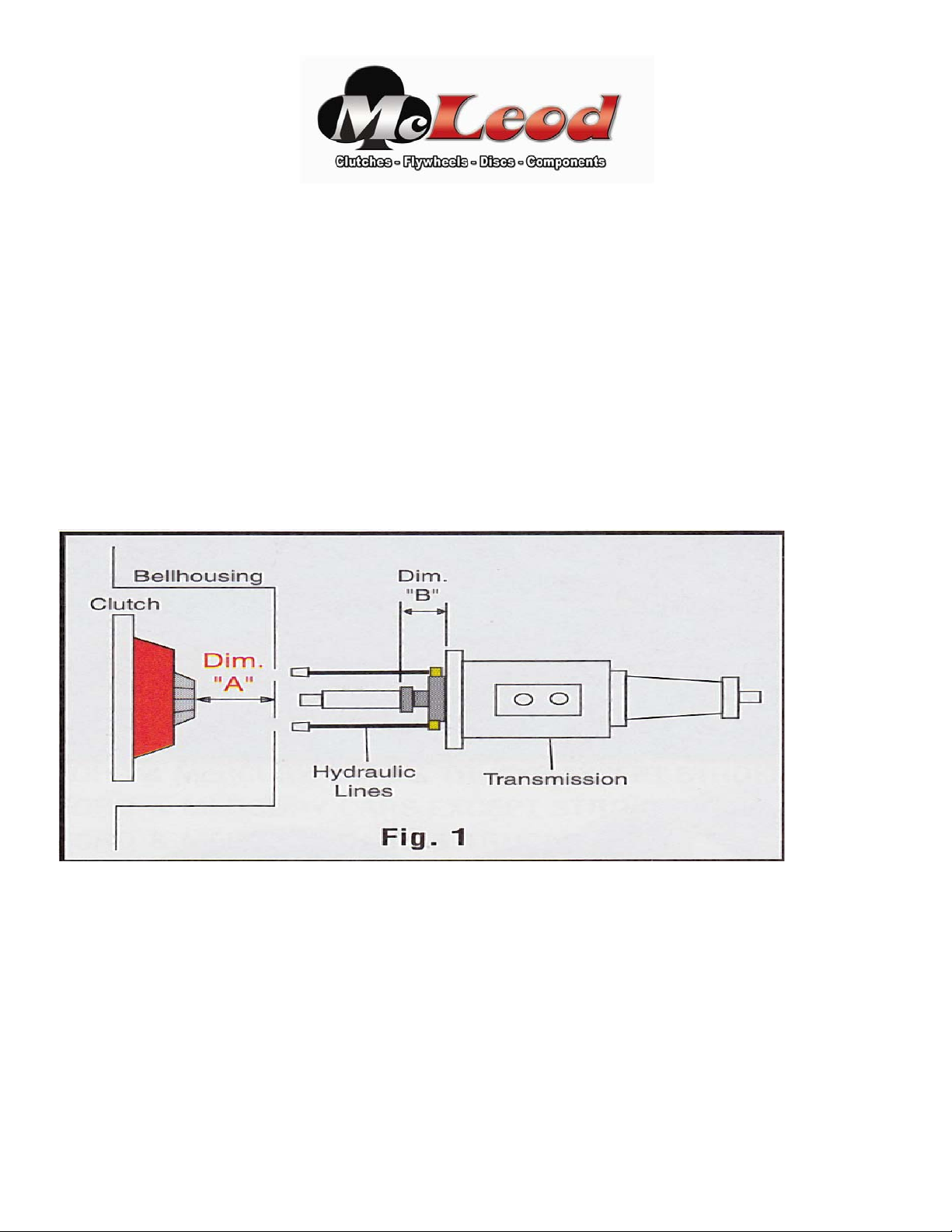
To Determine “Dimension A”: With the bell housing, flywheel, disc and pressure plate bolted to the
engine, measure the distance from the rear surface of the bell housing to the top of the release fingers on
the pressure plate. If this dimension measures less than 3” you should use a “Bolt-On” style hydraulic
throw out bearing assembly. If this dimension measures greater than 3” you should use a Slip-On style
hydraulic throw out bearing assembly.
Note: T-56 transmissions have a recessed front intermediate plate. Place a straight edge across the face of
the throw out bearing surface and measure to the front face of the front intermediate plate. The bearing
assembly on the T-56 is nested inside the front intermediate plate. This “B” dimension must be
determined to be certain you have the correct style bearing assembly. (Step 2).
1
McLeod Slip-On Style Hydraulic Throw-Out Bearing
Installation Instructions
Before installing the hydraulic Throw Out Bearing Assembly let’s take a look at your master cylinder and
pedal assembly combination. Key parts to the system:
1) Master cylinder bore size (3/4” recommended). Bore Diameter found on side of most aftermarket
master cylinders.
2) Clutch pedal travel.
3) Master cylinder “Push Rod” stroke should be 1”minimum.
4) 6:1 Pedal ratio. See
http://www.mcleodracing.com/info/?id=5262 for more info.
The master cylinder push rod needs a minimum of 1” of stroke if using a ¾” bore master cylinder. Less
travel is required with a larger diameter bore, although pedal effort will increase. More travel is required with a
smaller diameter bore, with decrease in pedal effort. If a larger than ¾” bore is required for your application, you
can ease pedal effort by mounting the master cylinder and push rod higher up the pedal toward the pivot point.
This will increase the amount of leverage you have with the pedal, thus an easier push. You will lose some push
rod travel by doing this however with the larger bore master cylinder you are dispensing more fluid per stroke to
compensate for the loss of pedal travel.
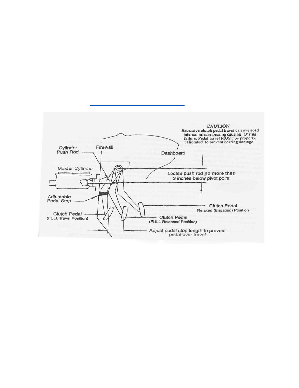
A 6 to 1 ratio is recommended with a ¾” bore master cylinder. Example…If the center of the pedal pad is
12” from the pivot point, the push rod connecting point should be 2” below the pivot point. Quick math: Pedal pad
is 12” below pivot point, divided by 6 (desired ratio) = 2”. Push rod should be attached to the pedal assembly 2”
from the pivot point.
An optional pedal stop may be attached to the pedal or the firewall. A bracket with a bolt and a jam nut
work nicely so that the stop is adjustable for more or less travel.
2
 Loading...