

Page 1
Magnum Force Clutch Installation Instructions
Congratulations! The Magnum Force clutch systems are capable of handling extremely high horsepower
engines in street driven and race vehicles. The strap drive kits are intended for street driven vehicles as
they do not rattle. The key benefits with this system are low rotating mass, relatively light pedal effort,
single, dual or triple discs for high torque capacity. Properly installed, this clutch system will provide the
strength and durability you have come to rely on in all of the McLeod Racing family of products. Dual disc
systems are shown throughout instructions. Single disc systems omit floater and triple disc systems
include additional floater and disc.
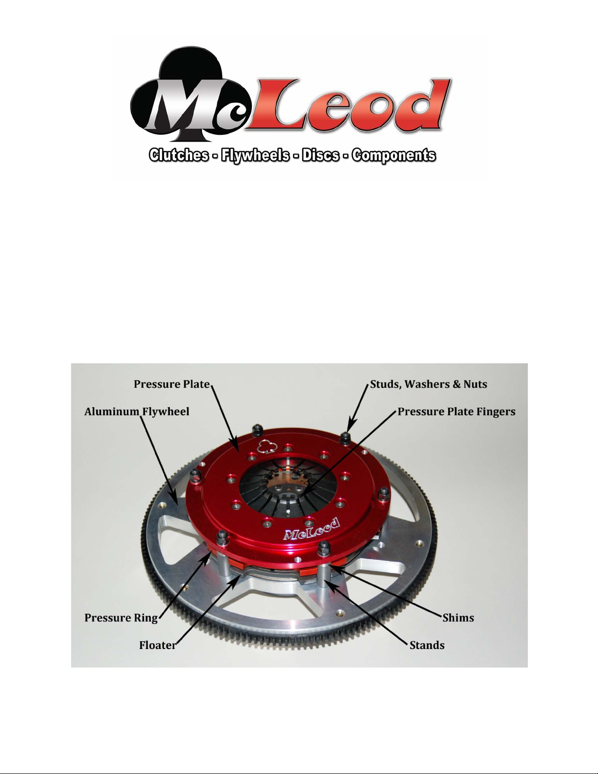
See Figure 1 Component Parts Identification
1) Remove six pressure plate nuts and flat washers and set aside.
I0008
Page 2
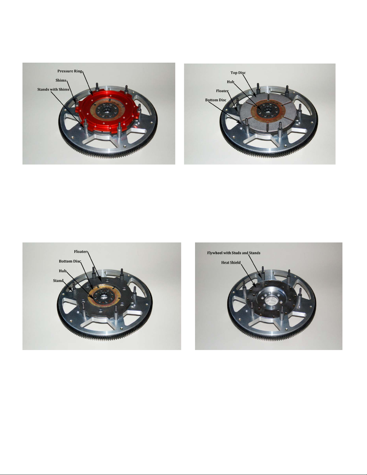
2) Lift off pressure plate, pressure ring and top disc and set aside. Reinstall nuts onto studs to retain
the shims and stands. Do Not Remove the Shims and Stands! Figure 2.
Figure 2 Figure 3
3) Caution: The shim packages on top of the stands are calibrated! Do not mix the shims!
Remove the shims only as a set and return the shims to the proper stud during reassembly!
4) Note the hub positioning when removing the top disc. This side of the disc assembly must be
toward the transmission. The flat side of the disc assembly with the large rivet heads must be
toward the flywheel. See Figure 3.
Figure 4 Figure 5
5) Note the engagement of the floater to the stands. Note the hub positioning when removing the
bottom disc. This side of the disc assembly must be toward the transmission. The flat side of the
disc assembly with the large rivet heads must be toward the flywheel. See Figure 4
6) This aluminum flywheel includes a heat shield for the disc contact surface to greatly improve
durability. These flywheels may also include a bolt on counter balance weight to match your
engine requirement. See Figure 5
7) Bolt the flywheel to the crankshaft using high quality fasteners (McLeod recommends ARP, Inc.).
Torque to recommended factory specs. Install pilot bushing into crankshaft.
Page 3
8) Install bottom disc, floater, top disc and alignment tool to properly align the discs. Install pressure
ring (shim packages if removed), pressure plate assembly, flat washers and nuts. With the nuts just
installed onto studs rotate the alignment tool to be certain the discs are aligned. Do not use thread
adhesive (LocTite) on the studs or nuts!
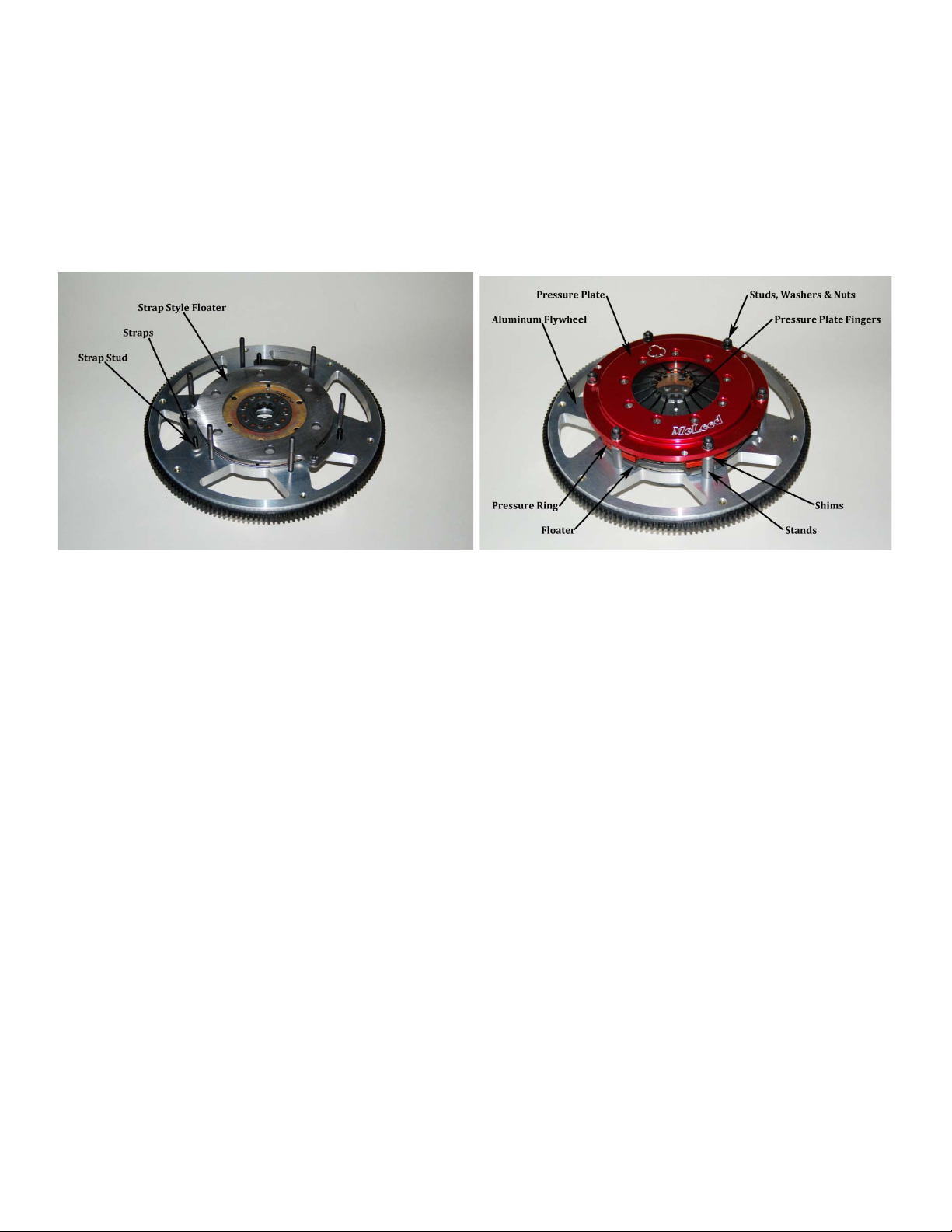
9) Strap Drive models only: Install bottom disc, floater with straps onto stud in flywheel, top disc,
pressure ring, (shim packages if removed) and pressure plate assembly. Both drive straps must be
offset and not on top of each other. The drive straps must be offset!! Do not use thread adhesive
(LocTite) on the studs or nuts! Tighten the strap nuts to 25 ft lbs. See Figure 6.
Figure 6 Figure 7
10) Pressure Plate tightening sequence is critical at this point. Tighten pressure plate nuts to 25
ft/lbs in a star pattern (1 o’clock, 7, 3, 9, 5, 11). Place a straight edge onto the pressure plate across
the fingers. When the nuts are properly tightened, the fingers will just contact the straight edge.
Final torque is determined when the diaphragm fingers are even with the straight edge. This
should be close to 35 ft/lbs…again tightening in the star pattern. See Figure 7.
11) Check diaphragm finger height at this time by placing a straight edge onto the pressure plate
across the finger opening. All of the fingers should be at the rear surface of the pressure plate.
12) Continue with the bell-housing, throw-out bearing and transmission installation.
13) Break-in period…Do not break-in this clutch system on a chassis dyno!!
14) Traction Control devices must be off!
15) Clutch adjustment is accomplished by removing shims as the discs wear. Each shim measures
.XXY” thick. Remove the same amount of shims from each stud when making adjustments!
Remember from Step 10 the adjustment is correct when the pressure plate nuts are tight and the
diaphragm fingers are even with the rear face of the pressure plate.
See page 4 for important clutch installation tips!!
Page 4

Important Clutch Installation Hints
The following check list is a reminder of the necessary inspection points
and precautions required to insure a trouble-free clutch installation.
Installation / Do’s
1) Determine cause of original clutch failure. Cause of first clutch failure (if not wear) MUST be found and
be corrected before installation of new clutch
corrected. If oil is present on clutch plate, cause of leak
unit.
2) Check splines on transmission input shaft for signs of abnormal wear or twisting. Slide new disc on spline
by hand gently to check fit. Disc should move FREELY on splines.
3) Remove ALL oil or grease from friction surfaces on flywheel and cover assembly. Surfaces
and dry. Also clean input shaft spline with a wire brush. Lubricate with dry graphite spray if needed.
4) To insure proper operation, friction surface of flywheel
be smooth and straight.
5) If throw-out bearing is worn, replace it, better now than later.
6) Closely inspect pilot bearing or bushing for excessive wear to avoid transmission shaft misalignment.
Replace it if any doubts.
7) Use clutch alignment tool to insure disc and cover are properly aligned with pilot bearing.
8) If using an aftermarket scatter shield/bell housing, checking center hole run-out is highly recommended.
9) Be sure all special type bolts, if any, are replaced in their proper locations.
10) Torque all clutch cover bolts evenly, to factory recommended spec, using a progressive “criss-cross”
tightening pattern.
11) Before completing installation, inspect all clutch linkage parts (fork, clevis, pins, etc.) for signs of wear and
replace ALL worn pieces. Grease all pivot points in linkage system.
12) Adjust clutch pedal “free play” to correct specifications. Throw-out bearing should not be tight against
clutch fingers. 1/8” – ¼” is recommended, except cable linkage.
Installation / Don’ts Torque Specs
1) Don’t let any grease or oil contact ANY friction Surface. 5/16-18 Grade 8 25 Ft/Lbs
2) Don’t use an impact (air gun) to tighten cover bolts. 3/8-16 Grade 8 35 Ft/Lbs
3) Don’t let transmission weight rest on input shaft during 7/16-20 Grade 8 65 Ft/Lbs
installation. ½-20 Grade 8 75 Ft/Lbs
MUST
MUST
be resurfaced. Check dowel pins, they must
MUST
be clean
Limited Warranty
McLeod Racing LLC, Products are warranted to be free from defects in material and workmanship for the period of ninety (90) days, from the date
of purchase. McLeod does not warrant or make any representations concerning its products when not installed and used strictly in accordance
with the manufacturer’s instructions for such; installation and operation, and in accordance with good installation and maintenance practices of
the automotive industry. McLeod will not be held liable for the labor charges and other intangible or consequent losses that might be claimed as a
result of the failure of any part, nor shall it be liable for damages or injury to persons or property resulting from the misuse or improper installation
of any part subject to this warranty.
No merchandise may be returned for any reason unless prior return merchandise authorization number (RMA) has been obtained from McLeod.
McLeod reserves the right to examine all parts returned for warranty claim to determine whether or not any such part has failed because of a
defect in material or workmanship. McLeod obligation under this warranty shall be limited to repairing, replacing or crediting, at its option, any
part found to be defective. All products returned to McLeod for warranty inspection must be prepaid by the customer under this warranty. There
are no other warranties, either expressed or implied, which extend beyond those set forth in the preceding paragraphs.
 Loading...