

Page 1
Soft Lok Clutch Instruction
Warning: DO NOT USE SOFT LOK ON ANY DYNO!!
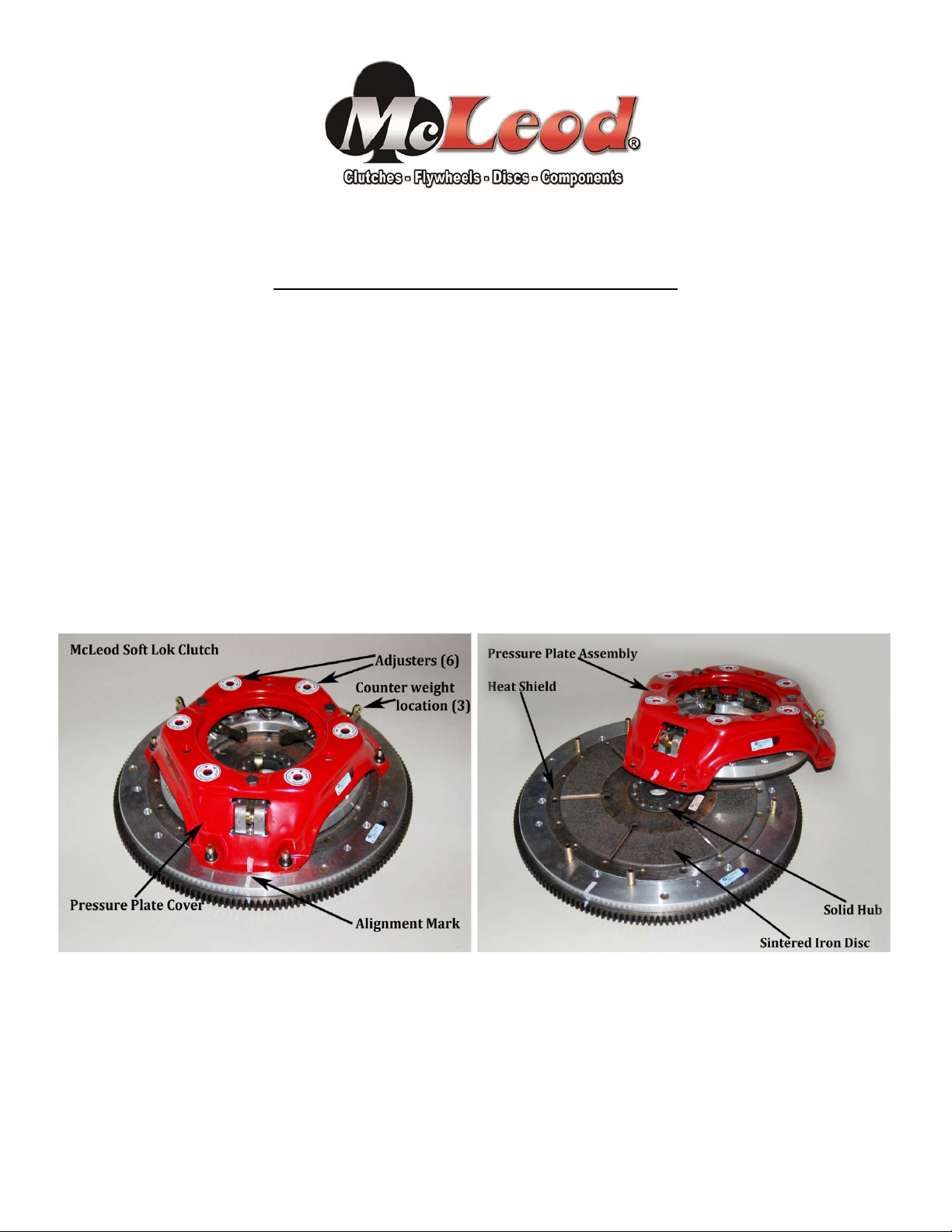
The Soft Lok clutch assemblies consist of an adjustable Ford/Long style pressure plate, sintered iron disc
and flywheel. Steel flywheels are normally used on engines that are under 450hp but usually are not
heavier than 22 lbs. Engines over 450hp use an aluminum flywheel with a steel insert. Car weight, tire
size and gearing do play into this decision. Call the McLeod Tech Line if you need a recommendation.
The McLeod Ford/Long style pressure plate has an aluminum pressure ring inside with a steel face
riveted to it. It has nine springs, six are adjustable. Most Soft Lok clutches have 200 lbs of base pressure.
Each of the six adjusters are found on either side of the levers. It is important to have steel surfaces on
either side of the disc to keep the same coefficient of friction.
The disc is sintered iron and is very aggressive. In order to control the aggression, McLeod reduced the
pressure in the pressure plate. This disc has a special characteristic and is expressed as: “The hotter it
gets, the harder it bites”. This will be explained further in these instructions.
Soft Lok Assembly shown with aluminum flywheel
PREPARATION:
When you receive your Soft Lok assembly, bolt it up to the flywheel. Remove the lever blocks
between the three levers and the pressure plate cover. Get yourself a T-Handle Allen wrench that fits the
six adjusters. (Helpful Hint: mark one of the ‘T’ by painting, striping or taping it). Put the T-Handle in one
of the adjusters and move it back and forth ½ turn. Get used to the feel of what base pressure feels like.
Page 2

You need to know how it feels because most often times you will make the adjustment to the clutch
12 turns of all (6) adjusters increases total pressure to 1760#
through a hole in the bellhousing; this will be covered in Phase 1. Once you are used to the feel we will
make the initial adjustment to the pressure. We want to have the clutch high enough so there is no
slippage in any gear. A good rule of thumb is to start at 8 – 10 turns. The adjuster turns just the opposite
of what one might think, counterclockwise adds pressure and clockwise take it out. If needed, mark the
bellhousing hole to reflect this. Start turning your T-Handle CCW until you feel tension on the Allen
screw. Check to see where the marked end is on the T-Handle and turn it 360 degrees for at least 8 – 10
turns. There will be a counterweight kit with your assembly. It has aluminum nuts, steel nuts and bolts
and steel weights. Put it in the toolbox until we get to the section on adjusting the clutch.
CONCEPT:
Most clutches are high-pressure lockup types. When you launch the car with these, the high
spring pressure will shock the car like pulling the trigger on a shotgun and feel like someone hitting the
back of the seat with a baseball bat. The trouble is it breaks parts and sometimes will cause the tires to
spin and get the car out of shape. Using the Soft Lok your ET and MPH will improve. You will have little
to no breakage because we are causing a controlled slip in the clutch that takes out all of the shock and
violence. Transmissions and rear ends last longer.
With its lower spring pressure and lighter weight, it will not hit the tires or chassis as hard and tire spin
can be controlled so traction is better and the lighter weight will let the engine rev quicker and pull
harder through mid range and top end.
Warning: Do not use the Soft Lok on any dyno!!
Do not drive the car onto the trailer or car hauler!!
Soft Lok Assembly with six adjusters
and a .280” thick Disc Base Pressure = 200#
1 turn of all (6) adjusters increases total pressure to 330#
2 turns of all (6) adjusters increases total pressure to 460#
3 turns of all (6) adjusters increases total pressure to 590#
4 turns of all (6) adjusters increases total pressure to 720#
5 turns of all (6) adjusters increases total pressure to 850#
6 turns of all (6) adjusters increases total pressure to 980#
7 turns of all (6) adjusters increases total pressure to 1110#
8 turns of all (6) adjusters increases total pressure to 1240#
9 turns of all (6) adjusters increases total pressure to 1370#
10 turns of all (6) adjusters increases total pressure to 1500#
11 turns of all (6) adjusters increases total pressure to 1630#
13 turns of all (6) adjusters increases total pressure to 1890#
Page 3

Important Clutch Installation Hints
The following check list is a reminder of the necessary inspection points
and precautions required to insure a trouble-free clutch installation.
Installation / Do’s
1) Determine cause of original clutch failure. Cause of first clutch failure (if not wear) MUST be found and
be corrected before installation of new clutch
corrected. If oil is present on clutch plate, cause of leak
unit.
2) Check splines on transmission input shaft for signs of abnormal wear or twisting. Slide new disc on spline
by hand gently to check fit. Disc should move FREELY on splines.
3) Remove ALL oil or grease from friction surfaces on flywheel and cover assembly. Surfaces
and dry. Also clean input shaft spline with a wire brush. Lubricate with dry graphite spray if needed.
4) To insure proper operation, friction surface of flywheel
be smooth and straight.
5) If throw-out bearing is worn, replace it, better now than later.
6) Closely inspect pilot bearing or bushing for excessive wear to avoid transmission shaft misalignment.
Replace it if any doubts.
7) Use clutch alignment tool to insure disc and cover are properly aligned with pilot bearing.
8) If using an aftermarket scatter shield/bell housing, checking center hole run-out is highly recommended.
9) Be sure all special type bolts, if any, are replaced in their proper locations.
10) Torque all clutch cover bolts evenly, to factory recommended spec, using a progressive “criss-cross”
tightening pattern.
11) Before completing installation, inspect all clutch linkage parts (fork, clevis, pins, etc.) for signs of wear and
replace ALL worn pieces. Grease all pivot points in linkage system.
12) Adjust clutch pedal “free play” to correct specifications. Throw-out bearing should not be tight against
clutch fingers. 1/8” – ¼” is recommended, except cable linkage.
Installation / Don’ts Torque Specs
1) Don’t let any grease or oil contact ANY friction Surface. 5/16-18 Grade 8 25 Ft/Lbs
2) Don’t use an impact (air gun) to tighten cover bolts. 3/8-16 Grade 8 35 Ft/Lbs
3) Don’t let transmission weight rest on input shaft during 7/16-20 Grade 8 65 Ft/Lbs
installation. ½-20 Grade 8 75 Ft/Lbs
MUST
MUST
be resurfaced. Check dowel pins, they must
MUST
be clean
McLeod Racing, LLC 1600 Sierra Madre Circle, Placentia, Ca 92870 714.630.2764
mcleodracing.com
Page 4
Bell Housing Alignment Procedure
When swapping a clutch, bell housing or
transmission it is highly recommended you check the
alignment of the bell housing to the engine
block/crankshaft and to the transmission input
shaft/output shaft. Think of this as a theoretical
straight line running through the crankshaft, through
the input shaft of the transmission and the output
shaft of the transmission. Misalignment along this
path can lead to leaks, poor clutch release, premature
wear of components and excessively noisy operation.
This inspection can be performed with a few common
measuring devices and some time.
Manufacturer’s tolerances of engine/crankshaft
alignment can vary especially if the engine block has
been modified throughout its lifetime or if you are
performing a bell housing and/or transmission swap.
If you find excess misalignment on your engine/bell
housing you can correct the problem with off-set
dowel pins. (Lakewood Industries offers Offset
dowel Pins to correct misalignment conditions). You
will need a dial indicator with a magnetic base along
with some typical hand tools to perform this
inspection. It is critical you pay close attention to
detail when performing this inspection in order to
achieve accurate assembly results.
1) Install flywheel onto crankshaft, using proper bolts and torque to factory setting.
2) Be certain the engine block dowel pins stick out of the rear of the engine block at least 3/8” for
proper bell housing engagement. Check the rear surface of the engine block at this time to be
certain it is free of nicks or burrs that will prevent the bell housing from seating against the block.
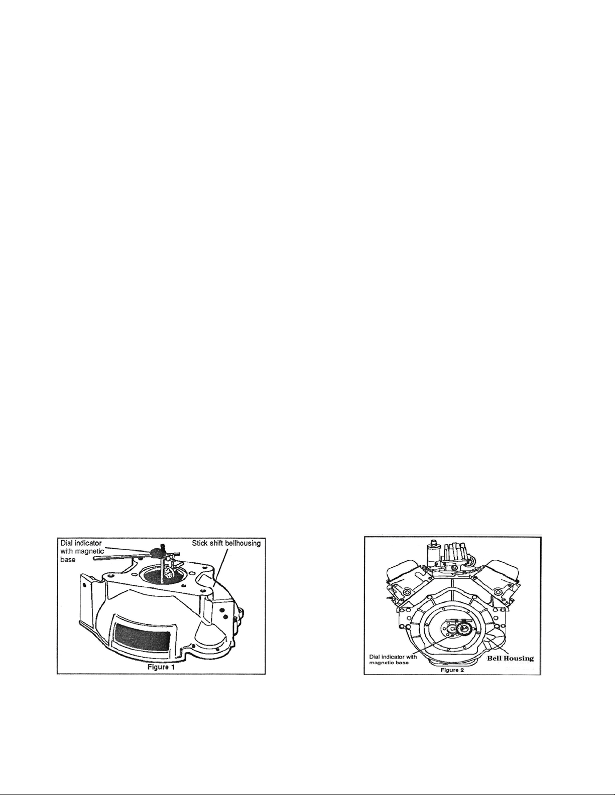
3) Install just the bell housing and hold in place with a few bolts. Install dial indicator base onto
crank flange or flywheel face and adjust plunger to contact the register bore of the bell housing.
Rotate the crankshaft and note the indicator reading as you sweep the register bore of the bell
housing.
4) Misalignment can be determined by dividing the change in the indicator by 2. Maximum allowable
runout is .005”.
5) If your reading exceeds .005” off-set dowel pins must be used to correct the misalignment.
Lakewood Industries offers such dowel pins in several sizes.
This alignment procedure will eliminate premature wear on many of the transmission and
clutch related components and will provide smoother operation. I0029
Page 5

 Loading...