

Page 1
POWER AMPLIFIER
CONTENTS
Performance Specifications ........................................ 2
Notes ......................................................................... 2
Rear Panel .................................................................. 3
Section Location ........................................................ 4
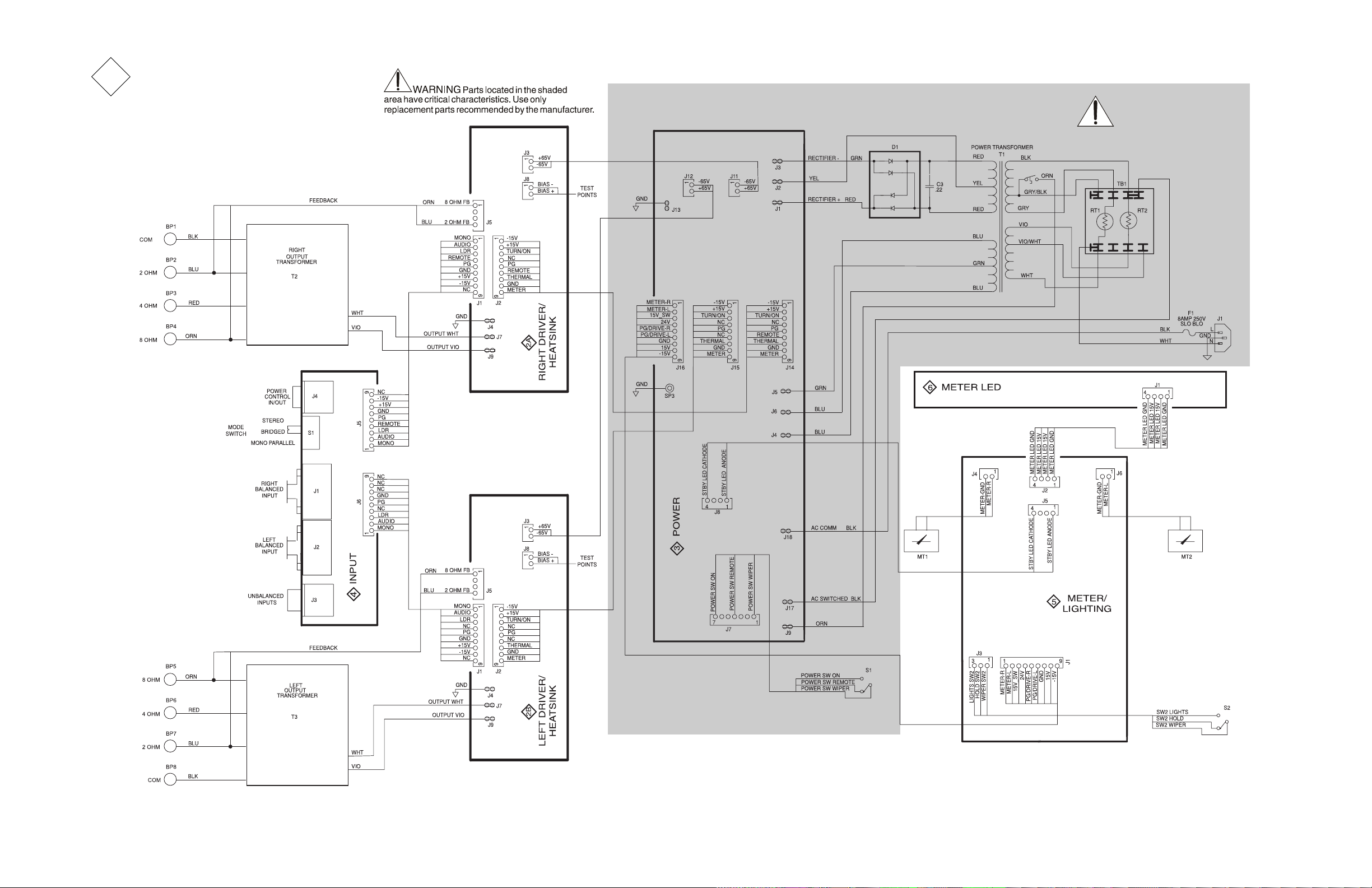
Block Diagram ...................................................... 5 - 6
Interconnection Diagram ...................................... 7 - 8
Heatsink Schematic and PCB ............................. 9 - 14
SERVICE MANUAL
Power Supply Schematic and PCB..................... 15 - 16
Input Schematic and PCB .................................. 17 - 18
Meter/Lighting Schematic and PCB .................... 19 - 21
Meter Led Schematic and PCB .......................... 21 - 22
Parts List ............................................................ 23 - 26
Exploded View and Parts List ............................. 27 - 32
Repacking Instructions ............................................. 33
Page 2

PERFORMANCE SPECIFICATIONS
Power Output Stereo
250 watts into a 2, 4 or 8 ohm load is the minimum sine
wave continuous average power per channel with both
channels operating
Power Output Mono Bridged
500 watts into a 4, 8 or 16 ohm load is the minimum sine
wave continuous average power output
Power Output Mono Bi-Amp
500 watts into a 1, 2 or 4 ohm load is the minimum sine
wave continuous average power output
Output Load Impedance
Stereo: 2, 4 or 8 ohms
Mono: 1, 2, 4, 8, or 16 ohms
Rated Power Band
20Hz to 20,000Hz
Total Harmonic Distortion
Maximum Total Harmonic Distortion at any power level
from 250 milliwatts to rated power output is 0.005%
Intermodulation Distortion
Maximum Intermodulation Distortion if instantaneous peak
output per channel does not exceed twice the rated output,
for any combination of frequencies from 20Hz to 20,000Hz,
with all channels operating is 0.005%
Dynamic Headroom
2.0dB
Sensitivity
1.6 Volts Unbalanced Input
3.2 Volts Balanced Input
A-Weighted Signal To Noise Ratio
112dB below rated output
Input Impedance
10,000 ohms
Wide Band Damping Factor
Greater than 40
Power Requirements
100 Volts, 50/60Hz at 8 amps
110 Volts, 50/60Hz at 7.2 amps
120 Volts, 50/60Hz at 6.6 amps
220 Volts, 50/60Hz at 3.3 amps
230 Volts, 50/60Hz at 3.3 amps
240 Volts, 50/60Hz at 3.3 amps
Note: Refer to the rear panel of the MC252 for the correct
voltage.
Overall Dimensions
17-1/2 inches (44.45cm) W , 9-7/16 inches (23.97cm) H,
14-3/4 inches (37.5cm) D, including clearance for connectors
Weight
94.5 pounds (207.9kg) net, 108.5 pounds (238.7kg) in
shipping carton
Frequency Response
+0, -0.25dB from 20Hz to 20,000Hz
+0, -3dB from 10Hz to 100,000Hz
NOTES
1. The heavy notes on the schematic denote the primary
signal path.
2. Unless otherwise noted, all voltages indicated on the
schematics are measured under the following conditions:
a. AC input at 120 volts, 50/60Hz.
b. All voltages are +/-10% with respect to ground. A
high impedance (10 megaohm) voltmeter must be used.
3 . Unless otherwise specified:
a. Resistor values are in ohms.
b. Capacitor values are microfarads (uF).
c. Inductor values are in microhenries (uH).
4 . On PC board drawings, Square pad indicates:
a. Polarized Capacitors - Positive
b. Diodes - Cathode
c. Others - Pin 1
5. WARNING
Parts marked with the symbol have critical
characteristics. Use only replacement parts recommended by the manufacturer.
2
Page 3
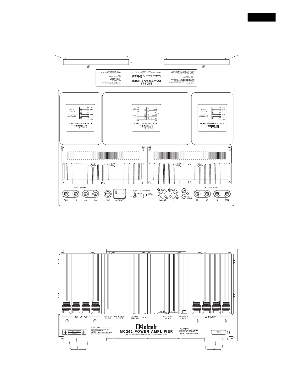
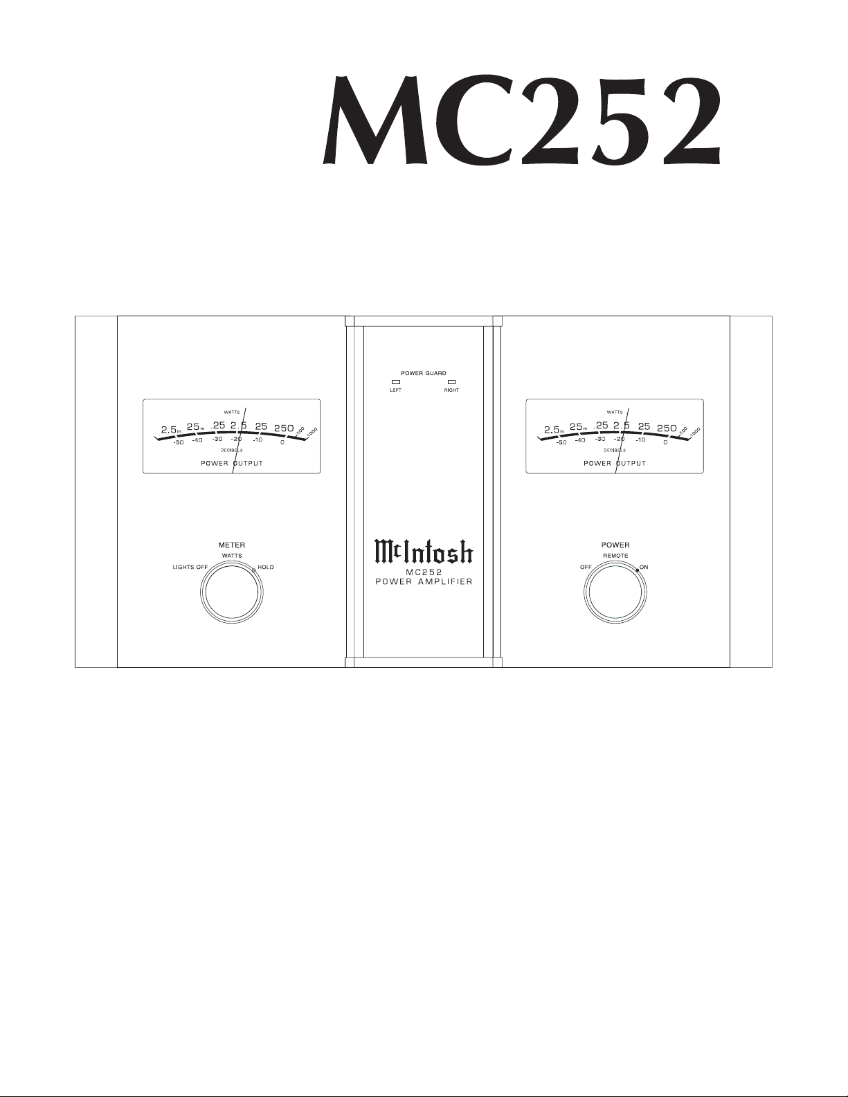
TOP AND REAR PANEL
MC252
3
Page 4
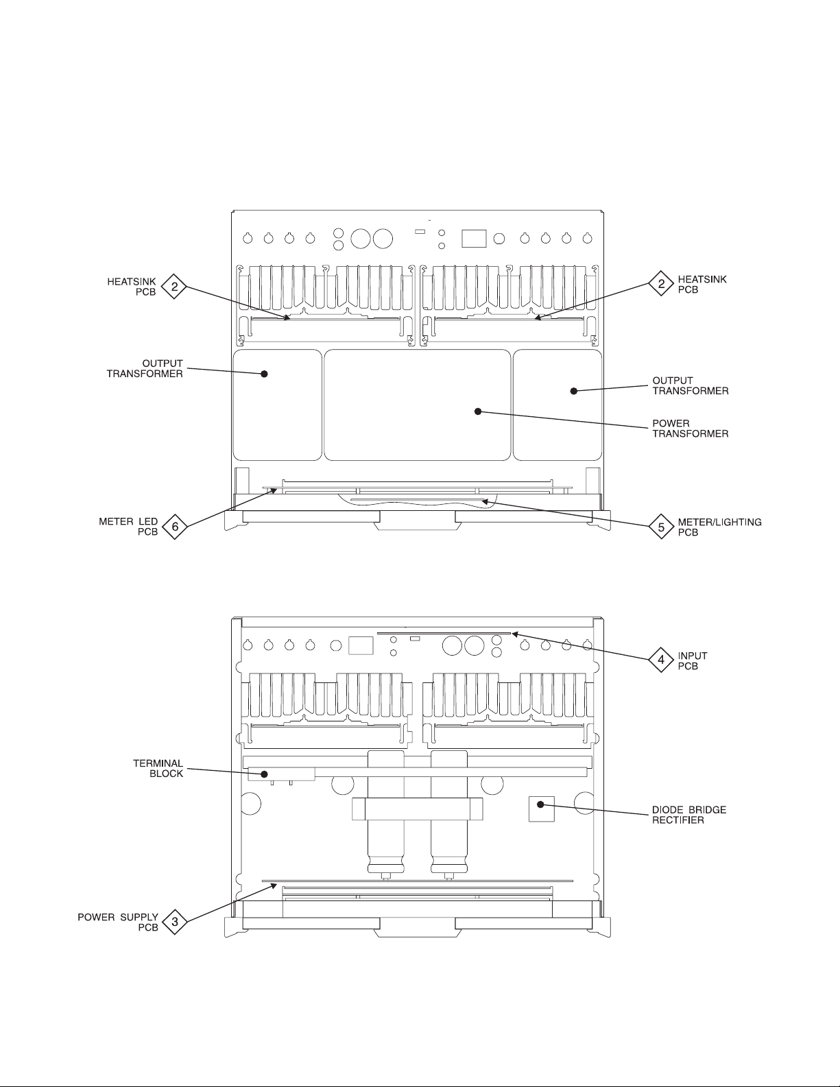
SECTION LOCATIONS
TOP VIEW WITH COVER REMOVED
BOTTOM VIEW WITH COVER REMOVED
4
Page 5
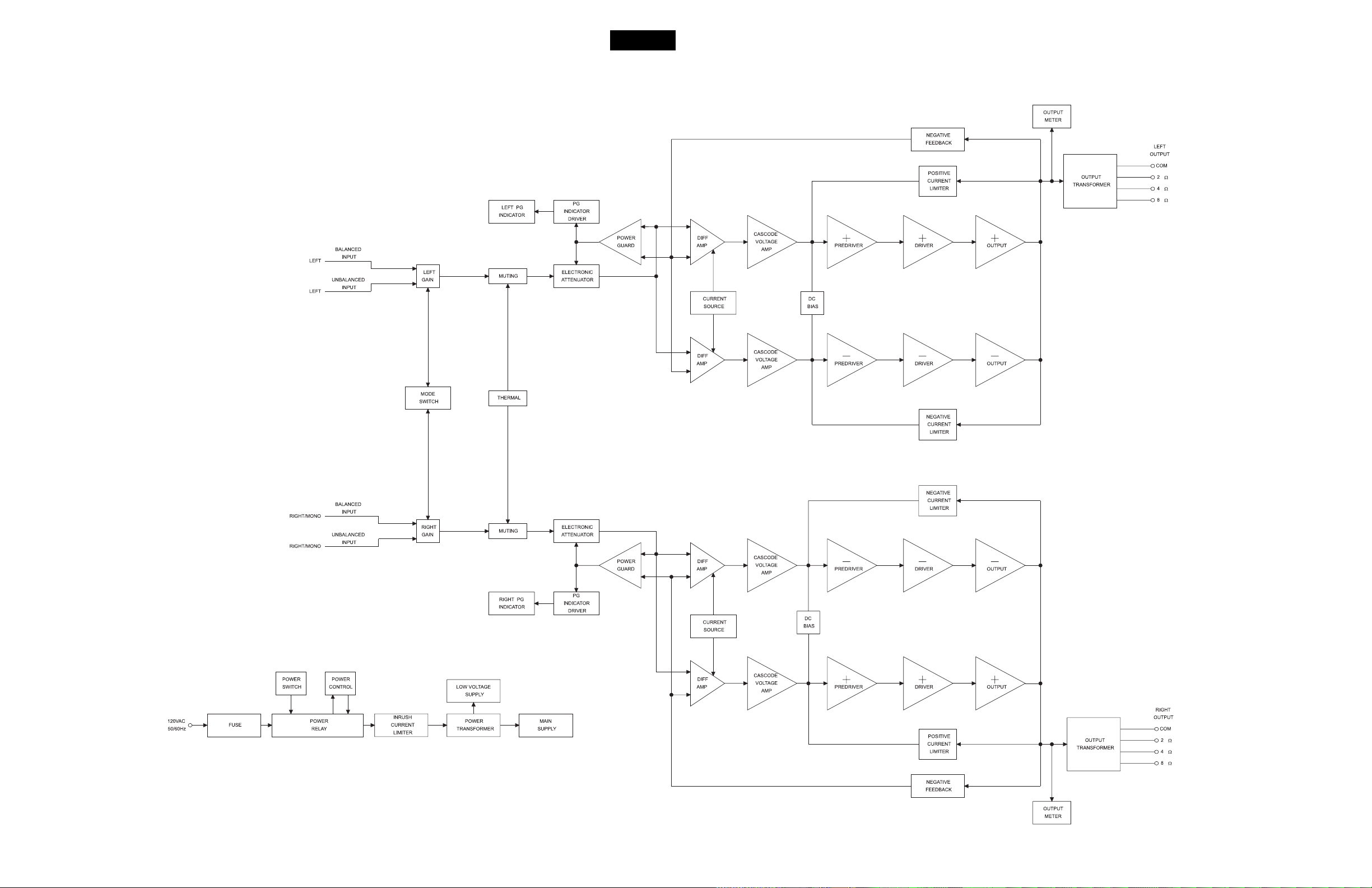
BLOCK DIAGRAM
MC252
5 6
Page 6
1
INTERCONNECT
7 8
Page 7

MC252
2A
2B
HEATSINK 049986
DRIVER SECTION
9 10
Page 8

2A 2B
HEATSINK 049986
HEATSINK SECTION
11 12
Page 9

MC252
2A 2B
HEATSINK 049986
13 14
Page 10

3
POWER SUPPLY 049757
15 16
Page 11

MC252
4
INPUT 049755
17 18
Page 12

5
METER/LIGHTING 049756
19 20
Page 13

MC252
5
METER/LIGHTING 049756
6
METER LED 049758
21 22
Page 14

PARTS LIST
Ref. No. Description Part No.
INTERCONNECT
1
BP1 Binding Post BLK 117741
BP2 Binding Post RED 117741
BP3 Binding Post RED 117741
BP4 Binding Post RED 117741
BP5 Binding Post RED 117741
BP6 Binding Post RED 117741
BP7 Binding Post RED 117741
BP8 Binding Post BLK 117741
D1 Diode Bridge Rectifier 070139
F1 Fuse 089105
J1 Receptacle, AC Line 117487
MT1 Meter 124084
MT2 Meter 124084
RT1 Thermistor Assembly 052008
RT2 Thermistor Assembly 052008
S1 Switch 146243
S2 Switch 146243
T1 Power Transformer 049763
T2 Output Transformer 049766
T3 Output Transformer 049766
TB1 Terminal Block AC 074091
2B
2A
049986 HEATSINK
C1 CAP DISC MONO .47UF 50V 061249
C2 CAP MONO .1uF 50V 20% Z5U 061305
C3 CAP MONO .1uF 50V 20% Z5U 061305
C4 CAP ELECT 47UF 35V 066446
C5 CAP ELECT 10UF 100VDC 066462
C6 CAP ELECT 10UF 100VDC 066462
C7 CAP MONO .1uF 50V 20% Z5U 061305
C8 CAP MONO .1uF 50V 20% Z5U 061305
C9 CAP MONO 220PF 100V 10PO 061301
C10 CAP MONO 100PF 100V 10% NPO 061300
C11 CAP MONO 100PF 100V 10% NPO 061300
C12 CAP ELECT 220UF 25V 066507
C13 CAP MPF 0.0047UF 5VDC 064308
C14 CAP POLYPROP 0.15UF 10VDC 064363
C15 CAP POLYPROP .047UF 10VDC 064364
C16 CAP ELECT 10UF 100VDC 066462
C17 CAP ELECT 10UF 100VDC 066462
C18 CAP MONO .01UF 50V 20% X7R 061304
C19 CAP ELECT 47UF 35V 066446
C20 CAP ELECT 47UF 35V 066446
C21 CAP MONO .01UF 50V 20% X7R 061304
C22 CAP MONO .1uF 50V 20% Z5U 061305
C23 CAP MONO 100PF 100V 10PO 061300
C24 CAP MONO 100PF 100V 10% NPO 061300
C25 CAP MONO .1uF 50V 20% Z5U 061305
C26 CAP MPF 0.47UF 5/100VDC 064442
C27 CAP MPF 0.47UF 5/100VDC 064442
D1 DIODE SILICON 070047
D2 DIODE SILICON 070047
D3 DIODE SILICON 070047
D4 DIODE SILICON 070047
D5 DIODE SILICON 070047
D6 DIODE 200V 3A 070126
D7 DIODE 200V 3A 070126
J1 CONN MALE 9 POS FRICTION LK 117244
J2 CONN MALE 9 POS FRICTION LK 117244
J3 CONN HEADER 2 PIN 0.156 117404
J4 BLADE FASTON W/FEET 117708
J5 CONN 4 PIN 117215
J7 BLADE FASTON W/FEET 117708
J8 CONN 2 PIN MALE 117213
J9 BLADE FASTON W/FEET 117708
LD1 LDR NETWORK VTL5C9 144179
Q1 TRANSISTOR PNP 132224
Q2 TRANSISTOR NPN 132223
Q3 TRANSISTOR NPN 132223
Q4 TRANSISTOR N JFET 132222
Q5 TRANSISTOR N JFET 132222
Q6 TRANSISTOR N JFET 132222
Q7 TRANSISTOR NPN POWER 132255
Q8 TRANSISTOR SI NPN 25V 132254
Q9 TRANSISTOR NPN POWER 132255
Q10 TRANSISTOR PNP 132224
Q11 TRANSISTOR NPN POWER 132255
Q12 TRANSISTOR SI NPN 25V 132254
Q13 TRANSISTOR NPN 132223
Q14 TRANSISTOR SI NPN 25V 132254
Q15 TRANSISTOR NPN 132223
Q16 TRANSISTOR PNP 132224
Q17 TRANSISTOR NPN 25C3334C 132285
Q18 TRANSISTOR PNP 2SA32IC 132286
Q19 TRANSISTOR NPN SILICON 132171
Q20 TRANSISTOR PNP SILICON 132172
Q21 TRANSISTOR NPN 132223
Q22 TRANSISTOR NPN 25C3334C 132285
Q23 TRANSISTOR PNP 2SA32IC 132286
Q24 TRANSISTOR NPN 132268
Q25 TRANSISTOR PNP 132267
Q26 TRANSISTOR NPN POW 2SC5200 132291
Q27 TRANSISTOR PNP POW 2SA1943 132292
Q28 TRANSISTOR NPN POW 2SC5200 132291
Q29 TRANSISTOR PNP POW 2SA1943 132292
Q30 TRANSISTOR NPN POW 2SC5200 132291
Q31 TRANSISTOR PNP POW 2SA1943 132292
Q32 TRANSISTOR NPN POW 2SC5200 132291
Q33 TRANSISTOR PNP POW 2SA1943 132292
Q34 TRANSISTOR NPN POW 2SC5200 132291
Q35 TRANSISTOR PNP POW 2SA1943 132292
R1 RES MF 10 OHM 1% 1/4W 144157
R2 RES MF 10 OHM 1/4W
R3 RES MF 4.75K 1% 1/4W 144097
R4 RES MF 100 OHM 1% 1/4W 144196
R5 RES MF 475 OHM 1% 1/4W 144086
R6 RES MF 22.1K 1% 1/4W 144187
R7 RES MF 10M 1% 1/4W 144264
R8 RES MF 267K 1% 1/4W 144118
R9 RES MF 2.21K 1% 1/4W 144298
R10 RES MF 221 OHM 1% 1/4W 144172
R11 RES MF 267K 1% 1/4W 144118
R12 RES MF 47.5K 1% 1/4W 144108
R13 RES MF 47.5K 1/4W 144108
R14 RES MF 3.32K 1% 1/4W 144095
R15 RES MF 221 OHM 1% 1/4W 144172
R16 RES MF 1K 1% 1/4W 144090
R17 RES MF 221 OHM 1% 1/4W 144172
R18 RES MF 3.32K 1/4W 144095
R19 RES MF 221 OHM 1% 1/4W 144172
R20 RES MF 1K 1% 1/4W 144090
R21 RES MF 221 OHM 1% 1/4W 144172
R22 RES MF 499 OHM 1% 1/4W 144087
R23 RES MF 267K 1% 1/4W 144118
R24 RES MF 187K 1% 1/4W 144406
R25 RES MF 324 OHM 1% 1/4W 144338
R26 RES MF 324 OHM 1% 1/4W 144338
R27 RES MF 6.49K .5% 1/4W 144401
R28 RES MF 13.7K 1% 1/4W 144342
R29 RES MF 221 OHM 1/4W 144172
R30 RES WW 2 OHM 10% 5W 139005
144157
R31 RES WW 4 OHM 5W 139119
R32 RES FP 22 OHM 1/4W 5 137033
R33 RES FP 22 OHM 1/4W 5 137033
R34 RES MF 324 OHM 1/4W 144338
R35 RES MF 324 OHM 1/4W 144338
R36 RES MF 2.21K 1/4W 144298
R37 RES MF 22.1K 1/4W 144187
R39 RES MF 22.1K 1/4W 144187
R40 RES MET OX 680 OHM 5% .5W 137093
R41 RES MET OX 680 OHM 5% .5W 137093
R42 RES MF 1.82K 1% 1/4W 144296
R43 RES MET OX 430 OHM 5% .5W 137095
R44 POT TRIM 200 OHM 20% HORIZ AD 134390
R45 RES MF 1.82K 1% 1/4W 144296
R46 RES MET OX 47 OHM 5% .5W 137096
R47 RES WW DUAL .47 OHM 5% 5W 139199
R48 RES WW DUAL .47 OHM 5% 5W 139199
R49 RES WW DUAL .47 OHM 5% 5W 139199
R50 RES WW DUAL .47 OHM 5% 5W 139199
R51 RES WW DUAL .47 OHM 5W 139199
R52 RES MF 1K 1% 1/4W 144090
R53 RES MF 1K 1% 1/4W 144090
R54 RES WW DUAL .47 OHM 5W 139199
R55 RES WW DUAL .47 OHM 5% 5W 139199
R56 RES WW DUAL .47 OHM 5% 5W 139199
RT1 SENSOR THERMAL 144249
U1 IC OPAMP NE4558N 133028
3
049757 POWER SUPPLY
C1 CAP POLY .047UF 10% 250VDC 064364
C2 CAP ELECT 10UF 50V 066445
C3 27000uF 100V ELECTROLYTIC 066489
C4 27000uF 100V ELECTROLYTIC 066489
C5 CAP ELECT 22UF 100V 066506
C6 CAP ELECT 3300UF 35V 066509
C7 CAP ELECT 3300UF 35V 066509
C8 CAP ELECT 4.7UF 50V 066512
C9 CAP ELECT 10UF 100VDC 066462
D1 DIODE RECTIFIER 070131
D2 DIODE RECTIFIER 070131
D3 DIODE RECTIFIER 070131
D4 DIODE RECTIFIER 070131
D5 DIODE RECTIFIER 070131
D6 DIODE RECTIFIER 070131
D7 DIODE SILICON 070047
HS1 HEATSINK T0220 080014
HS2 HEATSINK T0220 080014
J1 BLADE FASTON W/FEET 117708
J2 BLADE FASTON W/FEET 117708
J3 BLADE FASTON W/FEET 117708
J4 BLADE FASTON W/FEET 117708
J5 BLADE FASTON W/FEET 117708
J6 BLADE FASTON W/FEET 117708
J7 CONN MALE 7 PIN 117217
J8 CONN 4 PIN 117215
J9 BLADE FASTON W/FEET 117708
J11 CONN HEADER 2 PIN 0.156 117404
J12 CONN HEADER 2 PIN 0.156 117404
J13 BLADE FASTON W/FEET 117708
J14 CONN MALE 9 POS FRICTION LK 117244
J15 CONN MALE 9 POS FRICTION LK 117244
J16 CONN MALE 9 POS FRICTION LK 117244
J17 BLADE FASTON W/FEET 117708
J18 BLADE FASTON W/FEET 117708
K1 RELAY 48V 18.8mA 87052
Q1 TRIAC DRIV OPTOCPLR 600V 131022
Q2 TRANSISTOR NPN 132223
Q3 TRANSISTOR PNP 132224
23 24
Page 15

MC252
PARTS LIST con’t
Q4 TRANSISTOR NPN 132223
Q5 TRANSISTOR PNP 132224
Q6 TRANSISTOR P CHAN JUNC FET 132226
Q7 TRANSISTOR PNP 132224
R1 RES MF 33.2K 1% 1/4W 144015
R2 RES MF 33.2K 1% 1/4W 144015
R3 RES MF 2.74M 1/4W 144271
R4 RES WW 1.5K 10% 5W 139079
R5 RES MF 1.1K 1% 1/4W 144091
R6 RES MF 22.1K 1% 1/4W 144187
R7 RES MF 1M 1/4W 144269
R8 RES MF 12.1K 1% 1/4W 144154
R9 RES MF 2.1K 1% 1/4W 144299
R10 RES MF 12.1K 1% 1/4W 144154
R11 RES MF 3.32K 1% 1/4W 144095
R12 RES MF 20K 1% 1/4W 144104
R13 RES MF 2.1K 1% 1/4W 144299
R14 RES MF 150K 1% 1/4W 144419
R15 RES WW 2.7 OHM 10W 139173
R16 RES WW 2.7 OHM 10W 139173
SP1 BRACKET PCB CARD MOUNTING 003611
SP2 BRACKET PCB CARD MOUNTING 003611
SP3 BRACKET PCB CARD MOUNTING 003611
SP4 BRACKET PCB CARD MOUNTING 003611
U1 IC REGULATOR 15V 133154
U2 IC REGULATOR -15V 133153
049755 INPUT
4
C1 CAP ELECT 10UF 50V 066445
C2 CAP ELECT 10UF 50V 066445
C3 CAP ELECT 10UF 50V 066445
C4 CAP ELECT 10UF 50V 066445
C5 CAP MONO 47PF 200V 10% NPO 061299
C6 CAP MONO 22PF 200V 10% NPO 061298
C7 CAP MONO 47PF 200V 10% NPO 061299
C8 CAP MONO 22PF 200V 10% NPO 061298
C9 CAP MONO 22PF 200V 10% NPO 061298
C10 CAP MONO 22PF 200V 10% NPO 061298
C11 CAP MONO .1uF 50V 20% Z5U 061305
C12 CAP ELECT 10UF 50V 066445
C13 CAP MPF 0.22UF 5% 63VDC 064329
C14 CAP MONO .1uF 50V 20% Z5U 061305
C15 CAP MONO .1uF 50V 20% Z5U 061305
J1 XLR FEM HORIZ PCB WITH LATCH 117814
J2 XLR FEM HORIZ PCB WITH LATCH 117814
J3 JACK PHONO GOLD PJ261G 117436
J4 JACK HEADPHONE DUAL BLK 1/8 117825
J5 CONN MALE 9 POS FRICTION LK 117244
J6 CONN MALE 9 POS FRICTION LK 117244
R1 RES MF 20K 1% 1/4W 144104
R2 RES MF 20K 1% 1/4W 144104
R3 RES MF 20K 1% 1/4W 144104
R4 RES MF 20K 1% 1/4W 144104
R5 RES MF 20K 1% 1/4W 144104
R6 RES MF 20K 1% 1/4W 144104
R7 RES MF 20K 1% 1/4W 144104
R8 RES MF 20K 1% 1/4W 144104
R9 RES MF 40.2K 1% 1/4W 144107
R10 RES MF 40.2K 1% 1/4W 144107
R11 RES MF 20K 1% 1/4W 144104
R12 RES MF 40.2K 1% 1/4W 144107
R13 RES MF 1K 1% 1/4W 144090
R14 RES MF 20K 1% 1/4W 144104
R15 RES MF 1K 1% 1/4W 144090
R16 RES MF 40.2K 1% 1/4W 144107
R17 RES MF 20K 1% 1/4W 144104
R18 RES MF 20K 1% 1/4W 144104
R19 RES MF 3.32K 1% 1/4W 144095
R20 RES MF 3.32K 1% 1/4W 144095
R21 RES MF 20K 1% 1/4W 144104
R22 RES MF 100 OHM 1% 1/4W 144196
R23 RES MF 68.1 OHM 1% 1/4W 144082
R24 RES MF 1M 1/4W 144269
R25 RES MF 20K 1% 1/4W 144104
R26 RES MF 10 OHM 1% 1/4W 144157
R27 RES MF 10 OHM 1% 1/4W 144157
S1 JSA4320-0201 148069
SP1 BRACKET PCB CARD MOUNTING 003611
U1 IC OPAMP NE4558N 133028
U2 IC NAND SCHMIT 2-IN X 4 133192
U3 IC REGULATOR +5 VOLT 133093
5
049756 METER/LIGHTING
C4 CAP MONO .1uF 50V 20% Z5U 061305
C5 CAP MONO .1uF 50V 20% Z5U 061305
C8 CAP MPF 0.22UF 5% 63VDC 064329
C9 CAP MPF 0.1UF 100V 064337
C10 CAP ELECT 10UF 50V 066445
C11 CAP MONO .1uF 50V 20% Z5U 061305
C12 CAP MONO .1uF 50V 20% Z5U 061305
C13 CAP MPF 0.22UF 5% 63VDC 064329
C14 CAP MPF 0.1UF 100V 064337
C15 CAP ELECT 10UF 50V 066445
D1 DIODE ZENER 8.2V 1/2W 070130
D9 LED AMBER 058133
D13 LED AMBER 058133
D14 DIODE SILICON 070047
D15 DIODE SILICON 070047
D16 DIODE SILICON 070047
D17 DIODE SILICON 070047
D18 DIODE SILICON 070047
D19 DIODE SILICON 070047
D20 DIODE SILICON 070047
D21 DIODE SILICON 070047
D22 DIODE SILICON 070047
D23 DIODE SILICON
D24 DIODE SILICON 070047
D25 DIODE SILICON 070047
DS5 LED GREEN 5MM HI-INTENSITY 058165
DS6 LED GREEN 5MM HI-INTENSITY 058165
DS7 LED GREEN 5MM HI-INTENSITY 058165
DS8 LED SQUARE RED 058109
J1 CONN MALE 9 POS FRICTION LK 117244
J2 CONN 4 PIN 117215
J3 CONN 3 POS MLE MTS100 NORM 117214
J4 HEADER 2 PIN LATCHING 117766
J5 CONN 4 PIN 117215
J6 HEADER 2 PIN LATCHING 117766
Q1 TRANSISTOR NPN 132223
Q2 TRANSISTOR NPN 132223
Q3 TRANSISTOR NPN 132223
Q4 TRANSISTOR NPN 132223
Q8 TRANSISTOR NPN 132223
Q9 TRANSISTOR NPN 132223
Q10 TRANSISTOR NPN 132223
Q11 TRANSISTOR NPN 132223
Q12 TRANSISTOR NPN 132223
Q13 TRANSISTOR NPN 132223
Q14 TRANSISTOR NPN 132223
Q15 TRANSISTOR NPN 132223
R6 RES MF 187K 1% 1/4W 144406
R8 RES MF 12.1K 1% 1/4W 144154
R9 RES MF 475K 1% 1/4W 144364
070047
R11 RES MF 4.75K 1% 1/4W 144097
R13 RES MF 681 OHM 1% 1/4W 144195
R18 RES MF 12.1K 1% 1/4W 144154
R19 RES MF 4.75K 1% 1/4W 144097
R28 RES MF 562 OHM 1/4W 144408
R29 RES MF 806 OHM 1/4W 144089
R37 RES MF 187K 1% 1/4W 144406
R38 RES MF 681 OHM 1% 1/4W 144195
R39 RES MF 475K 1% 1/4W 144364
R40 RES MF 200K 1/4W 144117
R41 RES MF 10.2K 1% 1/4W 144130
R42 RES MF 10M 1% 1/4W 144264
R43 RES MF 2.21M 1/4W 144265
R44 RES MF 100 OHM 1% 1/4W 144196
R45 RES MF 187K 1% 1/4W 144406
R46 RES MF 1.21K 1% 1/4W 144191
R47 RES 82.5K 1/4W 144112
R48 POT TRIM 100K OHM 20% 134383
R49 RES MF 221K 1% 1/4W 144421
R50 RES MF 6.81K 1/4W 144297
R51 RES MF 100 OHM 1% 1/4W 144196
R53 RES MF 200K 1/4W 144117
R54 RES MF 10.2K 1% 1/4W 144130
R55 RES MF 10M 1% 1/4W 144264
R56 RES 82.5K 1/4W 144112
R57 RES MF 2.21M 1/4W 144265
R58 RES MF 187K 1% 1/4W 144406
R59 RES MF 6.81K 1/4W 144297
R60 POT TRIM 100K OHM 20% 134383
R61 RES MF 1.21K 1% 1/4W 144191
U1 IC DUAL OPERATIONAL AMP 133260
U2 IC DUAL OPERATIONAL AMP 133260
6
049758 METER LED
DS1 LED BLUE 5MM HI-INTENSITY 058166
DS2 LED BLUE 5MM HI-INTENSITY 058166
DS3 LED GREEN 5MM HI-INTENSITY 058165
DS4 LED GREEN 5MM HI-INTENSITY 058165
DS5 LED BLUE 5MM HI-INTENSITY 058166
DS6 LED BLUE 5MM HI-INTENSITY 058166
DS7 LED GREEN 5MM HI-INTENSITY 058165
DS8 LED GREEN 5MM HI-INTENSITY 058165
J1 CONN 4 PIN RIGHT ANGLE 117240
R1 RES MF 221 OHM 1% 1/4W 144172
R2 POT TRIM 500 OHM 20% HOR ADJ 134410
R3 RES MF 221 OHM 1% 1/4W 144172
R4 POT TRIM 500 OHM 20% HOR ADJ 134410
R5 RES MF 221 OHM 1% 1/4W 144172
R6 POT TRIM 500 OHM 20% HOR ADJ 134410
R7 RES MF 221 OHM 1% 1/4W 144172
R8 POT TRIM 500 OHM 20% HOR ADJ 134410
25 26
Page 16

EXPLODED VIEW
2827
Page 17

EXPLODED VIEW con’t
MC252
3029
Page 18

EXPLODED VIEW PARTS LIST
Ref
No.
1 016469 GLASS CENTER PANEL
2 016487 GLASS P ANEL W/HOLE
3 018717 END CAP
4 018711 CENTER EXTRUSION
5 018710 TOP/BOTTOM END CAP
6 049321 ASSY KNOB
7 104164 WASHER BLK FEL T 1 X 1 /4 X 1/16
8 094016 TAPE FOAM 1/4 X 1/8
9 100342 SCREW 6-32 X 3/8 FILLISTER HD
10 092426 FILTER COLOR METER
11 005351 GLASS PANEL, PLA TE
12 005312 PLATE GAP
13 101074 SCREW TAPPING 4-40 X 1/4 PH PN
14 100276 SCREW MACH SEMS 6-32 X 5/16 PH PN
15 005237 TITLE MOUNT
16 017913 LOGO BACKLIGHT
17 094430 TAPE FOAM WHITE 1/2W X 1/8 THK
18 101054 SCREW T APTITE 6-32 X 1/4 PH PN
19 017901 LOGO PUSHBUTTON BACKLIGHT
20 005239 SUBPANEL
21 146243 SWITCH POWER
22 021159 BUSHING SWITCH
23 021030 SPACER 6 X 1/4
24 049756 ASSY METER/LIGHTING PCB
25 102001 NUT KEP 4-40 CADMIUM PLATE
26 124084 METER
27 017881 BACKLIGHT METER
28 005229 METER PLA TE
29 102045 NUT KEP 6-32 SPECIAL
30 049758 ASSY METER LED PCB
31 104014 WASHER INT ST AR 3/8 X .507 X .002
32 005236 DUST COVER
33 100200 SCREW MACH 10-32 X 1/2 PH TRS HD
34 126948 DECAL TOP COVER
35 005234 CHASSIS
36 078025 GROMMET RUBBER 3/4ID
37 117741 POST BINDING BLK
38 117740 POST BINDING RED
39 178161 HOLDER FUSE 5 X 20mm IEC
40 117487 RECEPTACLE AC LINE
41 100250 SCREW MACH SEMS 6-32 X 1/4 PH PN
42 101197 SCREW HI-LO 4-24 X 3/8 PH HD BLK
43 049755 ASSY INPUT PCB
44 018690 HEA TSINK
45 084206 ISOSTRATE
Part
No.
Description
46 112087 SPACER PCB 1/4
47 114141 CLIP RIGHT ANGLE
48 101059 SCREW SM 6 X 5/8 PH PN TYPE A
49 049986 ASSY HEA TSINK PCB
50 005235 HEATSINK COVER
51 049766 POTTED TRANSFORMER OUTPUT
52 049763 POWER TRANSFORMER POWER
53 126946 DECAL OUTPUT TRANSFORMER
54 126947 DECAL POWER TRANSFORMER
55 101078 SCREW T AP 8-32 X 5/16 PH PN BLK
56 102006 NUT MACH 10-32 W/LOCK
57 101176 SCREW TC 6-32 X 1/2 PH PN TYPE F
58 102005 NUT MACH 8-32 W/LOCK
59 102003 NUT MACH 6-32 W/LOCK
60 104005 WASHER FLAT STEEL 6 X 3/8 X .032
61 070139 DIODE BRIDGE RECTIFIER
62 084135 THERMAL P AD
63 017452 KLIP WIRE
64 104016 WASHER INT ST AR .5 X .630 X .022
65 102052 NUT GOLD SUPPLIED W/117758
66 104162 WASHER LOCK INTERNAL TOOTH
67 102051 NUT HEX M9 X .75 GOLD PLA TED
68 005240 HEA TSINK VENT
69 049757 ASSY POWER SUPPL Y PCB
70 005238 CHASSIS SUPPORT BRACKET
71 005308 CAPACITOR STRAP
72 094391 TAPE FOAM 1/8 X 3/4 3M #4508
73 074091 TERMINAL BLOCK AC
74 104001 WASHER FLAT STEEL 4 X 9/32 X .025
75 104004 WASHER LOCK 5 X .255 INT STAR
76 102022 NUT MACH 4-40 X 3/16 X 1/16
77 005242 BOTTOM COVER
78 106007 SPRING CLIP LA TCH TYPE
79 017218 FOOT PLASTIC BLK
80 104080 WASHER FEL T #10 CLEAR ZINC
81 100159 SCREW MACH 10-32 X 3/4 PH PN BLK
82 100188 SCREW MACH SEMS 10-32 X 3/8
83 066489 CAP ELECT 2700uF 100V
84 101172 SCREW TC 6-32 X 1/4 PH FL U/C
85 094429 TAPE FOAM 1/32 THK
3231
Page 19

REPACKING INSTRUCTIONS
MC252
33
Page 20

POWER AMPLIFIER
SERVICE MANUAL
The continuous improvement of its products is the policy of McIntosh Laboratory Incorporated, who reserve the right to improve design without
notice. Because of the constant upgrading of McIntosh products’ circuitry and components, the Company cannot insure, and does not warrant, the
accuracy of the within schematic material, which is intended for information only.
McINTOSH LABORATORY, INC., 2 CHAMBERS STREET, BINGHAMTON, NEW YORK 13903 Printed in U.S.A. Part Number 040880
 Loading...