

Page 1

Rotary Lawnmower Owners Manual
Safety
Operation
Assembly
Maintenance
WARNING • PLEASE READ
For your own safety please read this manual before attempting to operate your new unit. Failure
to follow instructions can result in serious personal injury. Spend a few moments to familiarize
yourself with your mower before each use.
Model No. M48
AU
Page 2

AU
LAWN MOWER WARRANTY
The benefits conferred by this warranty are in addition to all other conditions and warranties in respect of
this product which the consumer may have taken under the Competition and Consumer Act 2010 or by any
legislation of a State or Territory of Australia. This product is warranted by Husqvarna Australia (ABN 45 115
475619)(the “Company”) to be free from defects in material and workmanship for a period of 24 months from
the date of original purchase. The Company during the period of the warranty, will at its option, and subject to
the conditions stated herein, repair or replace without charge this product or any component part, which upon
examination by an Authorised Service Agent or by the Company is found to be defective.
Warranty conditions
This warranty will not apply:
(i) where this product has been subjected to misuse, abuse, accident or want of care;
(ii) where this product has been used for a purpose for which it was not designed or is not suited;
(iii) where the service of this product has been undertaken by a person not authorised by the Company
to carry out such work or where parts that have not been approved by the Company have been used;
(iv) where this product has been used for industrial or commercial purposes.
Should service become necessary during the warranty period, the purchaser should contact an Authorised
Service Agent or the Company. In order to obtain warranty service, the purchaser must present the store
receipt showing the name of the retailer and the date of purchase together with a completed Warranty Card.
The period of the warranty begins from the original date of purchase, notwithstanding any subsequent repair
or parts replacement. No additional warranty or guarantee other than set out in this document, whether written
or verbal, is authorised to be made on the Company’s behalf. The purchaser shall be responsible for delivery
or causing the product to be delivered to the Company or the Authorised Service Agent and the purchaser
shall be responsible for all charges in connection with re-delivery of the product and/or the delivery of parts.
Damage in transit is not covered by this warranty and purchasers should remove from the product any liquids
(if applicable) before sending and pack the product securely to prevent damage.
Warranty exclusions
Normal wear parts or components are subject to separate terms as follows: Normal wear parts, components or
service required when performing normal and regular maintenance of this product are not covered by warranty
unless it is found to be defective by an Authorised Service Agent or by the Company. Normal wear parts
include, but are not limited to:
Worn Blades. Lubricants.
Spark Plugs. Engine Tune-ups.
Carburetor Tune-ups. Filters.
Returns based on the above listed normal wear parts will not be accepted under this warranty as they
are considered consumable items and are at the expense of the purchaser.
1
Page 3

AU
WARNING
Discharge openings must be guarded at all times. Do not remove the mulching
plug or hold the safety flap up while mowing.
TROUBLE SHOOTING
PROBLEM PROBABLE CAUSE
Throttle not in CHOKE position. Move throttle to CHOKE
Fuel tank is empty. Fill tank with fuel.
Air cleaner element is dirty. Clean air cleaner element.
Spark-plug loose. Tighten spark-plug to 25-30 N•m.
Spark-plug leads loose or disconnect
Engine does not start.
Engine difficult to start
or losses power
Engine operates
erratically.
Engine idles poorly.
Engine skips at speed.
Engine overheats.
Mower vibrates
abnormally.
from plug
Spark-plug gap is incorrect.
Spark-plug is defective. Install new, correctly gapped plug.
Carburetor is flooded with fuel.
Faulty ignition module. Contact the service agent.
Dirt, water or stale fuel tank.
Vent hole in fuel tank cap is plugged. Clean or replace fuel tank cap.
Air cleaner element is dirty. Clean air cleaner element.
Spark-plug is defective. Install new, correctly gapped plug.
Spark-plug gap is incorrect.
Air cleaner element is dirty. Clean air cleaner element.
Air cleaner element is dirty. Clean air cleaner element.
Air slots in engine shroud are blocked. Remove debris from shots.
Cooling fins and air passages under
engine fan housing are blocked.
Gap between electrodes or
spark-plug is too close.
Cooling air flow is restricted.
Incorrect spark-plug. Install correct spark plug.
Cutting assembly is loose.
Cutting assembly is unbalanced.
CORRECTIVE ACTION
Install spark-plug lead on spark plug.
Set gap between electrodes at
0.6 to 0.7mm.
Remove spark plug lead and remove
plug. Switch fuel tap off. Pull starter
rope 6 times to clear cylinder of fuel.
Clean and dry spark plug,then reinstall.
Drain fuel and clean tank. Fill tank with
clean, fresh fuel.
Set gap between electrodes at
0.6 to 0.7mm.
Remove debris from cooling fins and air
passages.
Set gap between electrodes at high 0.7
to .08mm
Remove any debris from slots in
shroud, blower housing, air passages
and cooling fins on engine.
Check and tighten blade and cutting
plate bolts.
Check blade and cutting plate for
damaged wear. Replace all damaged or
worn components.
2
Page 4

AU
Congratulations on your purchase of a quality McCulloch product.
This manual covers the operation and maintenance of the McCulloch walk behind mowers. Please read and understand this manual before using your new mower. If assistance is
required, please contact Husqvarna Australia or any McCulloch mower servicing dealer.
To emphasise special information the WARNING and CAUTION icons are used, please
observe these carefully.
WARNING
The safety of user and others involved. Personal injury may result if
information is disregarded.
CAUTION
Follow instructions to avoid mower damage and possible loss of warranty.
CONTENTS
Trouble shooting . . . . . . . . . . . . . . . . . . . . . . . . . . . . . . . . . . . . . . . . . . . . . . . . . . Pg 2
Specifications . . . . . . . . . . . . . . . . . . . . . . . . . . . . . . . . . . . . . . . . . . . . . . . . . . . . Pg 4
General Identification. . . . . . . . . . . . . . . . . . . . . . . . . . . . . . . . . . . . . . . . . . . . . . . Pg 4
Safety Instructions . . . . . . . . . . . . . . . . . . . . . . . . . . . . . . . . . . . . . . . . . . . . . . . . Pg 5
Assembly instructions . . . . . . . . . . . . . . . . . . . . . . . . . . . . . . . . . . . . . . . . . . . . . Pg 7
Preparing the engine . . . . . . . . . . . . . . . . . . . . . . . . . . . . . . . . . . . . . . . . . . . . . . Pg 8
Running the engine . . . . . . . . . . . . . . . . . . . . . . . . . . . . . . . . . . . . . . . . . . . . . . . Pg 10
Starting the engine . . . . . . . . . . . . . . . . . . . . . . . . . . . . . . . . . . . . . . . . . . . . . . . . Pg 11
Cut height control . . . . . . . . . . . . . . . . . . . . . . . . . . . . . . . . . . . . . . . . . . . . . . . . . Pg 13
Fitting the mulching plug to the mower . . . . . . . . . . . . . . . . . . . . . . . . . . . . . . . . Pg 14
Blade maintenance . . . . . . . . . . . . . . . . . . . . . . . . . . . . . . . . . . . . . . . . . . . . . . . . Pg 15
Maintenance schedule . . . . . . . . . . . . . . . . . . . . . . . . . . . . . . . . . . . . . . . . . . . . . Pg 16
Spark plug . . . . . . . . . . . . . . . . . . . . . . . . . . . . . . . . . . . . . . . . . . . . . . . . . . . . . . Pg 16
Engine air cleaner_ . . . . . . . . . . . . . . . . . . . . . . . . . . . . . . . . . . . . . . . . . . . . . . . . Pg 18
Mowing tips . . . . . . . . . . . . . . . . . . . . . . . . . . . . . . . . . . . . . . . . . . . . . . . . . . . . . . Pg 19
3
Page 5
AU
AU
SPECIFICATIONS
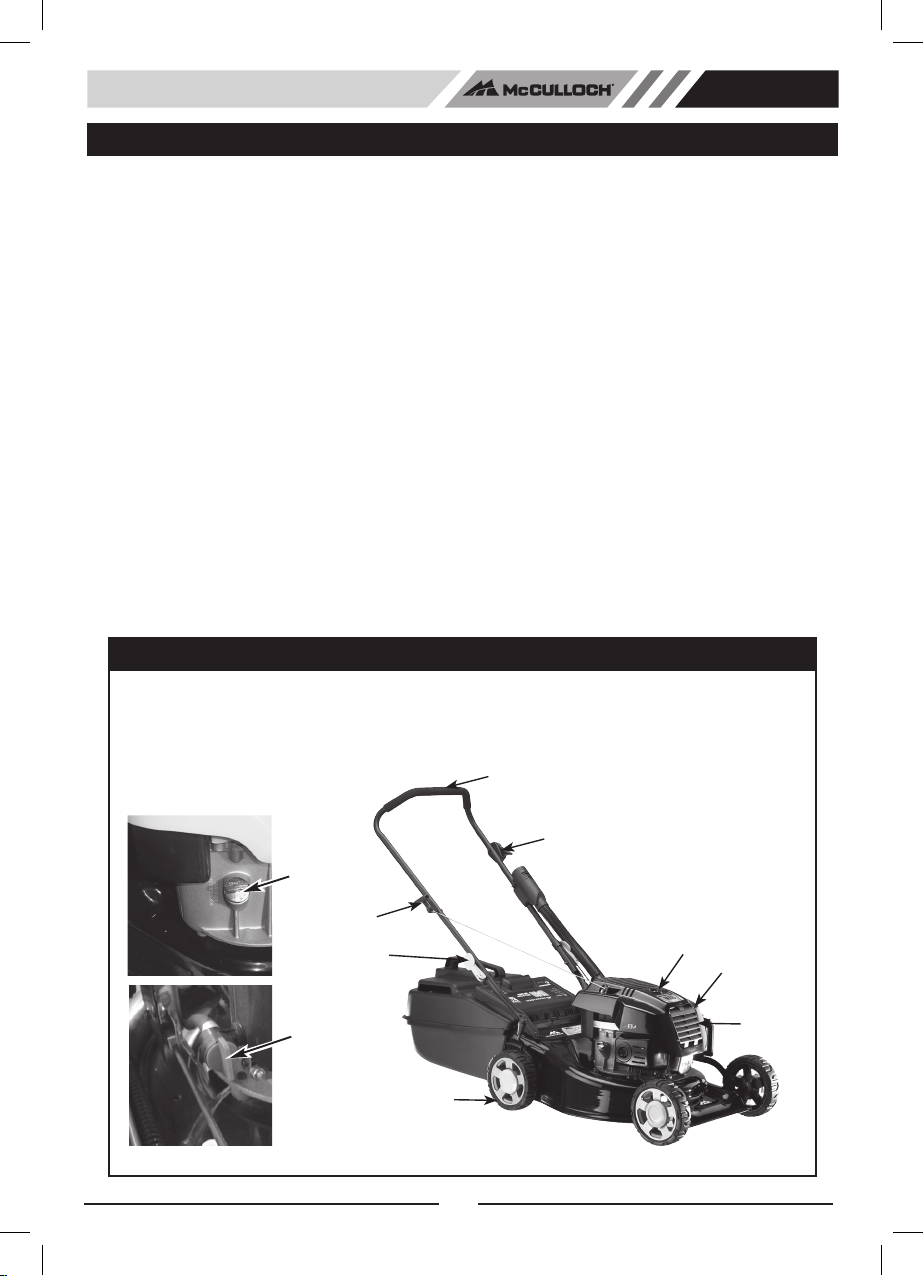
GENERAL IDENTIFICATION
1. Handle
2. Engine Control Lever
3. Air Cleaner
4. Locking Knob
5. Starter Handle
6. Fuel Filler Cap
7. Oil Filler Cap
8. Muffler Housing
9. Spark Plug
10. Wheels
11. Fuel Tap
1
2
4
5
6
8
9
10
CONTENTS
MODEL NO . . . . . . . . . . . . . . . . . . . . . . . . . . . . . . . . . . . . . . . . . . . . . . . . . . . . . . . . . . . . . . . . . . . . . . . . M48
Engine: . . . . . . . . . . . . . . . . . . . . . . . . . . . . . . . . . . . . . . . . . . . . . . . . . . . . . . . . .McCulloch OHV Four Stroke
Engine Speed . . . . . . . . . . . . . . . . . . . . . . . . . . . . . . . . . . . . . . . . . . . . . . . . . . . . . . . . . . . . . . . . . .3600 r.p.m
Fuel Tank Capacity . . . . . . . . . . . . . . . . . . . . . . . . . . . . . . . . . . . . . . . . . . . . . . . . . . . . . . . . . . . . . . . . . 900ml
Oil Tank Capacity . . . . . . . . . . . . . . . . . . . . . . . . . . . . . . . . . . . . . . . . . . . . . . . . . . . . . . . . . . . . . . . . . . 500ml
Air Filter Element . . . . . . . . . . . . . . . . . . . . . . . . . . . . . . . . . . . . . . . . . . . . . . . . . . . . . . . . . . . Paper Cartridge
Air Filter Location . . . . . . . . . . . . . . . . . . . . . . . . . . . . . . . . . . . . . . . . . . . . . . . . . . . . . . . . . . . . . . . . . . Engine
Cutting Width . . . . . . . . . . . . . . . . . . . . . . . . . . . . . . . . . . . . . . . . . . . . . . . . . . . . . . . . . . . . . . . . .480cm (19”)
Blades . . . . . . . . . . . . . . . . . . . . . . . . . . . . . . . . . . . . . . . . . . . . . . . . . . . . . . . . . . . . . . . . . . . . . 4 Swing Back
Height Adjustment . . . . . . . . . . . . . . . . . . . . . . . . . . . . . . . . . . . . . . . . . . . . . . . . . . . 12 Position Single Lever
Cutting Heights . . . . . . . . . . . . . . . . . . . . . . . . . . . . . . . . . . . . . . . . . . . . . . . . . . . . . . . . . . . . 15mm to 66mm
Wheel Size (F/Rmm) . . . . . . . . . . . . . . . . . . . . . . . . . . . . . . . . . . . . . . . . . . . . . . . . . . . . . . . . . . . .165/200mm
Bearing Type . . . . . . . . . . . . . . . . . . . . . . . . . . . . . . . . . . . . . . . . . . . . . . . . . . . . . . . . Dual Metal Ball Bearing
Tread . . . . . . . . . . . . . . . . . . . . . . . . . . . . . . . . . . . . . . . . . . . . . . . . . . . . . . . . . . . . . . . . . . . . . . . . . . . Rubber
Grass Catcher . . . . . . . . . . . . . . . . . . . . . . . . . . . . . . . . . . . . . . . . . . . . . . . . . . . . . . . . . . . . .53L Solid Plastic
Mulching Plug . . . . . . . . . . . . . . . . . . . . . . . . . . . . . . . . . . . . . . . . . . . . . . . . . . . . . . . . . . . . . . . . . . . Optional
Under Deck Wash Port . . . . . . . . . . . . . . . . . . . . . . . . . . . . . . . . . . . . . . . . . . . . . . . . . . . . . . . . . . . . . . . . .No
Weight (Incl. Catcher) . . . . . . . . . . . . . . . . . . . . . . . . . . . . . . . . . . . . . . . . . . . . . . . . . . . . . . . . . . . . . . . . 39kg
GENERAL IDENTIFICATION
1. Handle
2. Engine Control Lever
3. Air Cleaner
4. Locking Knob
5. Starter Handle
6. Fuel Filler Cap
7. Oil Filler Cap
8. Muffler Housing
9. Spark Plug
10. Wheels
11. Fuel Tap
7
5
4
11
10
1
2
9
8
3
4
Page 6

AU
SAFETY INSTRUCTIONS
WARNING
The safety of user and others involved. Personal injury may result if
information is disregarded.
• Inspect the area where the equipment is to be used and remove all stones, sticks, wire, bones
and other foreign, hard objects before mowing; they could be thrown by the blade.
• Never mow while barefoot or wearing open toe sandals or thongs.
Wear long trousers and heavy-duty shoes. It is advisable to wear suitable eye and hearin
protection.
• Read the Owner’s Manual carefully and know the controls. Learn how to stop the engine quickly
in an emergency.
• Stop the engine and disconnect the spark plug lead before attempting to clear blockages,
checking or working on the mower.
• Never attempt to adjust cutting height with the engine running.
• Never operate the equipment in wet grass, always be sure of your footings, keep a rm grip on
the handles and walk, never run and never walk backwards while cutting grass.
• Check all nuts, bolts and screws before starting. Always be sure your mower is in a safe
operating condition. Use only replacement parts made or guaranteed by Talon Tools.
• Refuel outdoors only. Do not smoke while refueling engine. Add fuel before starting the engine.
Never remove fuel cap with engine running or add petrol while the engine is running. If petrol is
spilt, do not attempt to start the engine. Clean all spilt fuel and move the mower away from the
spilled area. Avoid creating any source of ignition until petrol vapours have dissipated.
• Replace worn or damaged blades, as worn blades and worn bolts are major hazards.
• Mow only in good daylight.
• Do not operate the engine in a conned space where exhaust fumes can collect, as they can be
lethal.
• Do not put hands or feet near or under rotating parts. Always keep clear of the blades and
discharge opening.
• Stop the engine whenever you leave the mower even for a moment, before cleaning and when
making any adjustments or inspections.
• Mow across the face of slope, never up and down. Exercise extreme caution when changing
direction on slopes. Do not mow excessively steep slopes.
• Stop the engine when crossing gravel driveways, walks or roads.
• Start the engine carefully with feet well away from the blades.
• Store fuel in a cool place in an approved container specically designed for the purpose. In
general, plastic containers are unsuitable.
5
Page 7

AU
• Stop the engine and disconnect the spark plug lead before inspecting the mower if:
(a) the mower begins to vibrate abnormally, or
(b) after striking a foreign object.
• Check the catcher for wear and tear, and replace any worn or broken parts.
• To reduce re hazard, keep the engine free of grass, leaves and any spilt fuel.
• Shut the engine off and wait until the blades come to a complete stop before removing the
catcher or un-clogging the chute.
• Never pick up or carry a mower when it is operating.
• Replace worn or faulty silencers.
• Before using, always visually inspect to see that blades, blade bolts and cutter assembly
are not worn or damaged. Replace worn or damaged blades and bolts in sets to preserve
balance.
• Do not mow whilst people, especially children, or pets are in the mowing area.
• Do not allow children or people unfamiliar with these instructions to use the mower.
• Store the mower in a well-ventilated room away from naked ames such as may be found
in hot water heaters.
• Do not over-speed the engine or alter governor settings. Excessive speed is dangerous and
shortens mower life.
• Turn the fuel off at the conclusion of mowing and reduce the throttle setting during engine
run-out.
• Never cut grass while walking backwards.
• Walk, never run.
• Never use the mower unless the grass catcher, or guards provided, are in position.
6
Page 8

AU
ASSEMBLY INSTRUCTIONS
GRASS CATCHER
1. Position the two catcher halves as shown in
(Figure 1A).
Align the locating lugs marked 1 & 2 at the front of the
catcher. With the catcher base on the ground, push the
top section on each side of locator lug 1 until it clicks into
place. (Figure 1B).
Repeat this process for locator lug 2
2. Continue working from the front and push each locator lug
into position from number 1 through 8 until completed. i.e.
start with locator lug number 1 then 2, 3, 4, 5, 6, 7, and 8.
(Figure 1A)
3. WARNING:
DO NOT HIT THE CATCHER WITH YOUR HAND OR A
MALLET. This will break the plastic.
ALWAYS START AT POSITION 1. Do not try to assemble
the catcher from any other starting point as this will make
it difficult to assemble the clips.
4. Before use, check that all the lugs are completely clipped.
Test the assembly by holding the top handle and pushing
down of the base of the catcher. (Figure 1C)
FOLDING HANDLE
1. Lift the locking lever to release the handle bars for folding.
(Fig. 1D)
2. Push the locking lever closed to lock the handle bars in
the operating position.
3. Adjust the tension by turning the lock nut with an AF
spanner
GRASS CATCHER
1. To fit: Raise FLAP, grasp HANDLE and position catcher
against rear of mower.
2. To remove: grasp handle, lift FLAP, remove catcher. (Fig.
1E)
ASSEMBLY INSTRUCTIONS
AU
Please refer to the following sections when preparing the mower for it’s first use.
Figure. 1A
Figure. 1B
Figure. 1C
Locking lever
Figure. 1D
Locking
Lever
GRASS CATCHER
1. Position the two catcher halves as shown in
(Figure 1A).
Align the locating lugs marked 1 & 2 at the front of the
catcher. With the catcher base on the ground, push the
top section on each side of locator lug 1 until it clicks into
place. (Figure 1B).
Repeat this process for locator lug 2
2. Continue working from the front and push each locator lug
into position from number 1 through 8 until completed. i.e.
start with locator lug number 1 then 2, 3, 4, 5, 6, 7, and 8.
(Figure 1A)
3. WARNING:
DO NOT HIT THE CATCHER WITH YOUR HAND OR A
MALLET. This will break the plastic.
ALWAYS START AT POSITION 1. Do not try to assemble
the catcher from any other starting point as this will make
it difficult to assemble the clips.
4. Before use, check that all the lugs are completely clipped.
Test the assembly by holding the top handle and pushing
down of the base of the catcher. (Figure 1C)
FOLDING HANDLE
1. Lift the locking lever to release the handle bars for folding.
(Fig. 1D)
2. Push the locking lever closed to lock the handle bars in
the operating position.
3. Adjust the tension by turning the lock nut with an AF
spanner
GRASS CATCHER
1. To fit: Raise FLAP, grasp HANDLE and position catcher
against rear of mower.
2. To remove: grasp handle, lift FLAP, remove catcher.
(Fig.1E)
Figure. 1E
7
Page 9

AU
FUEL
USE ONLY CLEAN FRESH PETROL AT ALL TIMES, preferably unleaded, with an octane
rating of at least 91. Four stroke (cycle) engines use straight fuel.
FUEL FILLING
1. Position the mower on a level surface in a well-ventilated area.
2. Clean around the fuel tank.
3. Remove the fuel tank cap.
4. Place a clean funnel in the fuel filler.
5. Fill the fuel tank with unleaded petrol, allowing room in tank for fuel expansion.
6. Replace the fuel tank cap.
7. Clean up any spilt fuel.
ENGINE.
Regular attention to a few simple items will ensure long and trouble-free service from your
AU AU
Petrol vapour is highly flammable and explosive. Handle with extreme care.
Store in an approved container. Do not fill tank when engine is running or is
still hot. Do not allow open flame, matches or smoking nearby. Fill tank
outdoors in a well-ventilated area. Wipe away any spills and move the
mower away from any petrol fumes before starting engine.
When filling the fuel tank, always leave an air space of about 5mm to allow
for expansion of the fuel.
PREPARING THE ENGINE
CAUTION
FUEL
USE ONLY CLEAN FRESH PETROL AT ALL TIMES, preferably unleaded, with an octane
rating of at least 91. Four stroke (cycle) engines use straight fuel.
FUEL FILLING
1. Position the mower on a level surface in a well-ventilated area.
2. Clean around the fuel tank.
3. Remove the fuel tank cap.
4. Place a clean funnel in the fuel filler.
5. Fill the fuel tank with unleaded petrol, allowing room in tank for fuel expansion.
6. Replace the fuel tank cap.
7. Clean up any spilt fuel.
ENGINE.
Regular attention to a few simple items will ensure long and trouble-free service from your
mower. Carry out the regular maintenance described in the manual, and check the engine
mounting bolts regularly to be sure they are tight.
AU AU
Petrol vapour is highly flammable and explosive. Handle with extreme care.
Store in an approved container. Do not fill tank when engine is running or is
still hot. Do not allow open flame, matches or smoking nearby. Fill tank
outdoors in a well-ventilated area. Wipe away any spills and move the
mower away from any petrol fumes before starting engine.
When filling the fuel tank, always leave an air space of about 5mm to allow
for expansion of the fuel.
Before making any adjustments to your mower make sure that the engine is
turned off and that the blade has STOPPED ROTATING. Always disconnect the
spark plug wire and make sure it cannot accidentally contact the spark plug
before touching anything under the mower housing.
PREPARING THE ENGINE
CAUTION
Fig. 2
FULL
PREPARING THE ENGINE
Please read and understand the engine instructions prior to operating the lawnmower.
OIL – SAE30
DO NOT START your four-stroke engine before making sure that it has been
filled with the right amount of the correct grade of oil.
Four stroke (cycle) engines are shipped without oil. Place the mower on a level position, unscrew the ‘OIL
FILL’ cap and slowly pour oil provided into the sump. Fill to the full mark on the dipstick. The capacity is
approximately 500ml. To check engine oil level first unscrew the oil tank cap and wipe excess oil off. Insert
cap into oil filler but DO NOT screw in. Remove cap and observe oil level on dip stick. NOTE: There may
be a small amount of oil in the engine after draining. Fill using dip stick to avoid over lling.
CAUTION
Fig. 2
CHANGING THE ENGINE OIL.
FOUR STROKE ENGINES should be checked for oil level every 8 hours running (or daily),
and the oil should be drained and replaced after every 50 hours of use.
See Engine Lubrication section for oil change information.
Oil Fill
Fig. 3
8
FULL
Page 10

AU
WARNING
Petrol vapour is highly ammable and explosive. Handle with extreme care.
Store in an approved container. Do not ll tank when engine is running or
is still hot. Do not allow open ame, matches or smoking nearby. Fill tank
outdoors in a well-ventilated area. Wipe away any spills and move the
mower away from any petrol fumes before starting engine.
CAUTION
When lling the fuel tank, always leave an air space of about 5mm to allow
for expansion of the fuel.
USE ONLY CLEAN FRESH PETROL AT ALL TIMES, preferably unleaded, with an octane rating of at least
91. Four stroke (cycle) engines use straight fuel.
FUEL FILLING
1. Position the mower on a level surface in a well-ventilated area.
2. Clean around the fuel tank.
3. Remove the fuel tank cap.
4. Place a clean funnel in the fuel filler.
5. Fill the fuel tank with unleaded petrol, allowing room in tank for fuel expansion.
6. Replace the fuel tank cap.
7. Clean up any spilt fuel.
ENGINE.
Regular attention to a few simple items will ensure long and trouble-free service from your
mower. Carry out the regular maintenance described in the manual, and check the engine
mounting bolts regularly to be sure they are tight.
WARNING
Before making any adjustments to your mower make sure that the engine is
turned off and that the blade has STOPPED ROTATING. Always disconnect
the spark plug wire and make sure it cannot accidentally contact the spark
plug before touching anything under the mower housing.
9
Page 11

AU
RUNNING THE ENGINE
Ensure that the engine has been prepared correctly and that the fuel tap is turned ON. We
recommend that you check the oil level before every mowing session.
COLD STARTING
1. Set the engine control to the CHOKE position.
2. Turn the fuel tap to the “ON” position. (Fig. 6)
3. Stand to the right of the mower. Hold the top handle firmly with your left hand to hold
mower stationary. Grasp the starter rope handle and pull slowly until resistance is felt.
ENGINE CONTROL
This is mounted at the top left side of the handle (most models). It operates the choke, for
starting, and allows you to set the governed speed of the engine while cutting or to stop the
engine.
AU AU
RUNNING THE ENGINE
Ensure that the engine has been prepared correctly and that the fuel tap is turned ON. We
recommend that you check the oil level before every mowing session.
COLD STARTING
1. Set the engine control to the CHOKE position.
2. Turn the fuel tap to the “ON” position. (Fig. 6)
3. Stand to the right of the mower. Hold the top handle firmly with your left hand to hold
mower stationary. Grasp the starter rope handle and pull slowly until resistance is felt.
Then pull briskly.
Do not pull the starter rope with a jerk or release it until fully rewound.
4. When engine has warmed up for a short time move the engine control lever to the desired
speed position for cutting.
Fuel
tap
ENGINE CONTROL
This is mounted at the top left side of the handle (most models). It operates the choke, for
starting, and allows you to set the governed speed of the engine while cutting or to stop the
engine.
You will not need to change the control setting constantly while mowing because the
governor holds the selected speed, even under varying cutting loads. The positions for
CHOKE, FAST, SLOW and STOP are marked.
Fig. 4
AU AU
RUNNING THE ENGINE
ENGINE CONTROL
This is mounted at the top left side of the handle (most models). It operates the choke, for starting, and
allows you to set the governed speed of the engine while cutting or to stop the engine.
Fig. 4
You will not need to change the control setting constantly while mowing because the
governor holds the selected speed, even under varying cutting loads. The positions for
CHOKE, FAST, SLOW and STOP are marked.
Fig. 5
10
Page 12

AU
STARTING THE ENGINE
WARNING
Never run the engine indoors or in poorly ventilated areas. engine exhaust
contains carbon monoxide, an odourless and deadly gas. keep hands, feet,
hair and loose clothing away from moving parts.
STARTING THE ENGINE
Ensure that the engine has been prepared correctly and that the fuel tap is turned ON. We
recommend that you check the oil level before every mowing session.
WARNING
Never run the engine indoors or in poorly ventilated areas. engine exhaust
hair and loose clothing away from moving parts.
contains carbon monoxide, an odourless and deadly gas. keep hands, feet,
COLD STARTING
1. Set the engine control to the CHOKE position.
2. Turn the fuel tap to the “ON” position. (Fig. 6)
3. Stand to the right of the mower. Hold the top handle firmly with your left hand to hold
mower stationary. Grasp the starter rope handle and pull slowly until resistance is felt.
Then pull briskly.
Do not pull the starter rope with a jerk or release it until fully rewound.
4. When engine has warmed up for a short time move the engine control lever to the desired
speed position for cutting.
Fuel
tap
Fig. 6
11
Page 13

AU
HINTS FOR EASY STARTING
Stand the mower on a paved drive or path where the blade is clear of the grass. If you must
start on the lawn, move to an already cut area and/or raise the cutting height. Do not start the
mower on a gravel surface.
Start a warm engine with the control in the START position.
Keep the mower clean underneath
HARD START CHECKLIST
Look for these faults
Fuel 1. Insufficient fuel in tank
2. Fuel tap shut off
3. Stale fuel
4. Water or dirt in fuel
5. Blocked air vent in fuel tank cap
Ignition 1. Loose spark plug wire
2. Dirty spark plug electrodes
3. Incorrect spark plug gap
4. Incorrect spark plug type
Other 1. Choked air filter (dirt or oil)
2. Incorrect adjustment of engine control cable
3. Cutting blade obstructed
STOPPING
Move the engine control to STOP.
12
Page 14

AU
CUTTING HEIGHT CONTROL LEVER
Turn mower off before adjusting cutting height. The single point cut height control adjusts all four wheels
simultaneously. To operate, steady the mower by grasping the handle with one hand, pull the lever outwards from the mower with the other hand, and move it to the desired setting.
For heavy or very long grass it is recommended setting the mower cut height to #4 or more to avoid the
possibility of clogging. If clogging becomes persistent because of unfavourable conditions, try walking
slower, cutting a narrower strip or raising the cutting height further.
Fig. 7A
Fig. 7B
13
Page 15

AU
Check the blade mounting bolts at frequent intervals for proper tightness.
Check the blade condition frequently, particularly if the mower has hit a foreign object or is
vibrating. Sub-standard cutting and catching will result from a neglected blade. Your
Authorised Dealer can replace blades as necessary, or if you prefer, supply the parts for you
to do yourself.
BLADE CHANGE
1. Disconnect the spark plug wire.
2. Adjust the mower to the high cut position.
3. Lift the rear flap and prop open to give full access to the blades, use only Talon blade kit
number AO9228-305001.
4. Remove the blades, blade retaining bolts, nuts and washers and discard.
5. Fit the new blades, blade bolts, washers and nuts
in set sequence, refer drawing below (to loosen
rotate anti-clockwise, to tighten rotate clockwise).
Blade bolt torque : 14.8-22.0 ft-lb (20-30 N•m)
1. Stop the engine.
2. Make sure the discharge chute and the underside of the mower are clean. If not, clean the
mower.
3. Raise the flap with left hand, and using the hand-hold on the mulching plug, insert the
mulching plug, with the angled section to the mowers right, into the discharge chute. Make
sure the back of the plug is sitting on the rear axle, then lower the flap.
AU AU
FITTING THE MULCHING PLUG TO THE MOWER (OPTIONAL)
FITTING THE MULCHING PLUG TO THE MOWER (OPTIONAL)
1. Stop the engine.
2. Make sure the discharge chute and the underside of the mower are clean. If not, clean the mower.
3. Raise the flap with left hand, and using the hand-hold on the mulching plug, insert the mulching plug,
with the angled section to the mowers right, into the discharge chute. Make sure the back of the plug is
sitting on the rear axle, then lower the flap.
Fig. 8A
Fig. 8B
14
14
Page 16

AU
BLADES
number AO9228-305001.
in set sequence, refer drawing below (to loosen
rotate anti-clockwise, to tighten rotate clockwise).
Blade bolt torque : 14.8-22.0 ft-lb (20-30 N•m)
BLADES
CAUTION
Always use genuine original equipment parts to ensure safety and proper
performance. Substitute parts can be disappointing and dangerous.
Check the blade mounting bolts at frequent intervals for proper tightness.
Check the blade condition frequently, particularly if the mower has hit a foreign object or is
vibrating. Sub-standard cutting and catching will result from a neglected blade. Your
Authorised Dealer can replace blades as necessary, or if you prefer, supply the parts for you
to do yourself.
CAUTION
Always use genuine original equipment parts to ensure safety and proper
performance. Substitute parts can be disappointing and dangerous.
BLADE CHANGE
1. Disconnect the spark plug wire.
2. Adjust the mower to the high cut position.
3. Lift the rear flap and prop open to give full access to the blades.
4. Remove the blades, blade retaining bolts, nuts and washers and discard.
5. Fit the new blades, blade bolts, washers and nuts in set sequence, refer drawing below (to loosen
rotate anti-clockwise, to tighten rotate clockwise).
Blade bolt torque : 14.8-22.0 ft-lb (20-30 N•m)
Fig. 9A
Fig. 9B
15
Page 17

AU
MAINTENANCE
CAUTION
Never tip mower sideways. To gain access to blades or cutting disc tilt
backwards so spark plug is up.
ENGINE LUBRICATION
Check engine oil before every mowing session or every 5 hours or daily.
ENGINE MAINTENANCE SCHEDULE
CAUTION
Failure to properly service your mower will reduce it’s operating performance
and could void warranty. Service costs are not covered by warranty.
First 5 Hours
Change engine oil - Oil SAE30. 500ml.
Every 25 Hours or Every Season
Change engine oil if operated under heavy load or in high ambient temperature above 35°C.
SAE30. 500ml.
Clean air filter foam element or replace high air intake filter cartridge.
Every 50 Hours or Every Season
Change engine oil. Use 500 ml of SAE30 oil.
Clean air filter foam element or replace high air intake filter cartridge.
Clean mower.
Mower service should be carried out by an authorised Talon service agent.
STORAGE
If mower is to be stored for over 60 days, you will need to drain the fuel, if full,
to prevent gum from forming in fuel system or on essential carburettor parts.
Remove spark plug and pour about 10ml of engine oil into cylinder, replace spark plug and
turn engine over (pull cord slowly).
SPARK PLUG
Use only a McCulloch replacement spark plug. For best results, replace the
spark plug every 100 hours of use.
1. Stop the engine and remove the spark plug wire.
2. Remove spark plug
3. Screw the replacement spark plug into the engine and tighten to 25-30 N•m torque and
replace spark plug wire.
4. Spark plug gap. 0.6 – 0.7mm
16
Page 18

AU
CAUTION
Do not over-tighten the spark plug as engine damage may occur.
DECK CLEANING
Wipe deck with a damp cloth.
UNDER DECK CLEANING
1. Hose under deck by tilting the mower backwards so that the spark plug is up. Allow mower
to dry before storing.
CAUTION
Do not hose engine. Water can damage engine or contaminate the fuel system.
17
Page 19

AU
ENGINE AIR CLEANER
AU
MAINTENANCE
ENGINE AIR CLEANER
The engine air cleaner element must be serviced (cleaned) after 25 hours normal mowing.
TO REPLACE HIGH INTAKE PAPER AIR FILTER
1.
(Fig.12A)
2.
3.
4. Replace air snorkel and clip into place.
CAUTION
Do not allow dirt or dust to clog the air filter element.
CAUTION
Do not allow dirt or dust to clog the air lter element.
ENGINE AIR CLEANER
The engine air cleaner element must be serviced (cleaned) after 25 hours normal mowing.
TO REPLACE HIGH INTAKE PAPER AIR FILTER
1. To access filter element push down air snorkel release clip pull air snorkel away from air filter box.
(Fig.12A)
2. Remove old air filter element and replace with new. (Fig.12B)
3. Insert new filter into housing so that the end with the opening fits into the inner tube in the housing.
4. Replace air snorkel and clip into place.
Fig. 12A Fig. 12B
18
Page 20

AU
MOWING TIPS
• The best time to mow your lawn is the early afternoon. By this time the grass has had a chance to dry
out. Also the sensitive newly cut grass area isn’t exposed to the direct sun.
• For healthy growth, grass should not be cut too short. Using the lowest settings can result in
destruction of the crown of grass, allowing flat lying weeds to develop.
• Vary your cutting pattern from week to week. One week mow your lawn from north to south, the next
week, mow your lawn from east to west. This will help prevent matting and graining of the grass.
• For best performance, always keep the mower blade sharp. A blunt blade tends to tear, not cut, the
blades of grass.
• When cutting very long grass, a preliminary cut on a high setting, followed by a lower cut (preferably a
day or so later), will minimise the overall time required for the job.
• Do not try to cut too much off the grass at one time. This can cause excessive loads to be put on the
engine and also affect the mulching performance.
• It is recommended that the lowest cut height setting when mulching is #4. For best results when
mulching, cut off only the top third (or less) of the grass. Cutting lower than this will have a detrimental
effect on the mulching performance.
• When mulching, turning the mower at the end of a strip you may notice unmulched grass. The mower
deck is naturally tilted upward when turning so that the air-flow which holds the grass in position for
re-cutting is momentarily decreased. After mowing the lawn, you can go back and mow only the turns
so that the clippings are no longer visible.
• Clean the mowing chamber frequently to remove grass build-up. This will keep mowing performance
at its best, especially when mulching. Avoid cutting your lawn when it is wet. Wet grass tends to form
clumps and interferes with the mulching action of the mower.
• If you are not collecting the cut grass, mow in a pattern that deposits the clippings on the previously
cut path. So, if your mower discharges clippings on the left, the next cut should be to the right of the
previous one, and vice-versa.
• When cutting close to obstructions such as tree trunks, and when mowing to the edge of a lawn where
there is no wheel support, use the left side of the mower, giving a useful blade ‘overhang’ for ready
access to awkward areas.
19
Page 21

AU
NOTES:
20
 Loading...