


GB
FR
DE
ES
IMPORTANT INFORMATION: Please read these instructions carefully and make
sure you understand them before using this unit. Retain these instructions for future reference.
MANUEL D’INSTRUCTIONS
RENSEIGNEMENTS IMPORTANTS: Avant d’utiliser cet appareil, veuillez lire atentivement les instructions et assurez--vous de les avoir comprises. Conservez les instructions pour référence ultérieure.
BETRIEBSANWEISUNG
WICHTIGE INFORMATION: Lesen Sie diese Hinweise zur Handhabung des Geräts aufmerksam durch. Verwenden Sie es erst, wenn Sie sicher sind, daß Sie alle Anweisungen verstanden haben und gut aufbewahren.
MANUAL DE INSTRUCCIONES
INFORMACIÓN IMPORTANTE: Lea atentamente las instrucciones y
asegúrese de entenderlas antes de utilizar esta aparato. Conserve las instrucciones para la referencia en el futuro.
115306026 Rev. 1 1/31/10 BRW
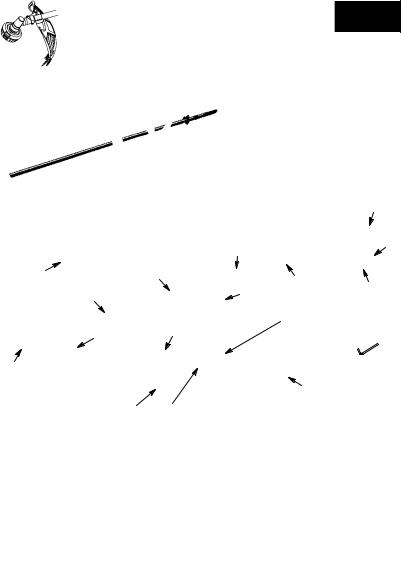
TABLE OF CONTENTS
Identification (What is What?) |
2 |
Service & Adjustments |
16 |
|
Identification of Symbols |
3 |
Storage |
18 |
|
Safety Rules |
3 |
|||
Troubleshooting Table |
19 |
|||
Assembly |
5 |
|||
Declaration of Conformity |
20 |
|||
Operation |
9 |
|||
|
|
|||
Maintenance |
15 |
Technical Data |
21 |
|
|
|
|
|
|
|
|
|
|

 16 6
16 6
7
 20
20
21
11
22
1. |
Fuel tank |
13. |
Throttle trigger |
23 |
|
||||
2. |
Loop handle |
14. |
Throttle lock--out |
|
3. |
ON/STOP switch |
15. |
Starter handle |
5 |
4. |
Shoulder strap clamp |
16. |
Fuel cap |
|
5. |
Shoulder strap |
17. |
Primer bulb |
|
6. |
Trimmer head |
18. |
Start lever |
|
7. |
Line limiter blade |
19. |
Muffler |
|
8. |
Shield |
20. |
Wrench |
|
9. |
Shaft |
21. |
Hex wrench |
|
10. |
J--handle |
22. |
Instruction manual |
|
11. |
Blade |
23. |
Transport guard |
|
12. |
Coupler |
|
|
|
2

IDENTIFICATION OF SYMBOLS
A. |
|
D. |
|
F. |
|
I. |
|
|
B. |
|
|
E. |
|
G. |
|
J. |
|
|
|
|
|
|
||||
|
|
|
|
|
||||
C. |
|
|
|
|
H. |
|
K. |
|
|
|
|
|
|
|
|||
|
|
|
|
|
|
|||
|
|
|
|
|
|
|
|
|
A. WARNING! This brushcutter can be dangerous! Careless or improper use can cause serious or even fatal injury.
B.Read and understand the instruction manual before using the brushcutter.
C.Always use:
Ear protection, eye protection, head protection, boots, and gloves.
D.DANGER! Blade can thrust violently away from material it does not cut. Blade thrust
can cause amputation of arms or legs. Keep people and animals 15 meters away. WARNING! Blade/trimmer line can throw objects violently. You and others can be
blinded or injured. Always wear eye protection and leg protection.
F.The operator of the machine must insure that no one comes within a 15 meter radius while working. When several operators are working within the same area a safety distance of at least 15 meters must be observed.
G.Use unleaded or quality leaded petrol and two--stroke oil mixed at a ratio of 2.5%.
H.Assist handle to be positioned only below the arrow.
I.Engine ON/STOP switch.
J.Guaranteed sound power level according to Directive 2000/14/EC
K.Maximum rotational frequency of the spindle, rpm
SAFETY RULES
 WARNING: When using gardening
appliances, basic safety precautions should always be followed to reduce the risk of fire and serious injury. Read and follow all instructions.
 DANGER: This power tool can be dan-
gerous! This unit can cause serious injury including amputation or blindness to the operator and others. The warnings and safety instructions in this manual must be followed to provide reasonable safety and efficiency in using the unit. The operator is responsible for following the warnings and instructions in this manual and on the unit. Read the entire instruction manual before assembling and using the unit! Restrict the
use of this unit to persons who read, understand, and follow the warnings and instructions in this manual and on the unit. Never allow children to operate this unit.
INSTRUCTION |
SAFETY INFORMATION |
MANUAL |
ON THE UNIT |
 DANGER: Blade can thrust violently
away from material it does not cut. Blade thrust can cause amputation of arms or legs. Keep people and animals 15 meters away.
 WARNING: Blade/trimmer line can
throw objects violently. You and others can be blinded or injured. Wear safety glasses and leg protection.
3

 WARNING: Hazard zone for thrown
objects. Blade/Trimmer line can throw objects
violently. Others can be blinded or injured. Keep people and animals 15 meters away.
Hazard Zone
 WARNING: Do not use trimmer head as a fastening device for the blade.
 WARNING: The blade continues to
spin after the throttle is released or, engine is turned off. The coasting blade can throw objects or seriously cut if accidentally touched. Stop the blade by contacting the right hand side of the coasting blade with material already cut.
Stop coasting blade by contact with cut material.
OPERATOR SAFETY
 WARNING: This machine produces
an electromagnetic field during operation. Under some circumstances, this field may interfere
with active or passive medical implants. To reduce the risk of serious or fatal injury, we recommend persons with medical implants to consult
their physician and the medical implant manufacturer before operating this machine.
S Dress properly. Always wear safety glasses or similar eye protection when operating, or performing maintenance, on your unit (safety glasses are available). Eye protection should be marked Z87.
S Always wear a helmet if the trees to be cleared are taller than 2 meters.
SAlways wear face or dust mask if operation is dusty.
S Always wear heavy, long pants, long sleeves, boots, and gloves. Wearing safety leg guards is recommended.
S Always wear foot protection. Do not go barefoot or wear sandals. Stay clear of blade/spinning line.
SSecure hair above shoulder length. Secure or remove loose clothing or clothing with loosely hanging ties, straps, tassels, etc. They can be caught in moving parts.
SBeing fully covered also helps protect you from debris and pieces of toxic plants
thrown by spinning line.
SStay alert. Do not operate this unit when you are tired, ill, upset or under the influence of alcohol, drugs, or medication. Watch what you
are doing; use common sense.
SWear hearing protection. Long or continuous exposure to high noise levels may cause permanent hearing impairment.
SNever start or run inside a closed room or building. Breathing exhaust fumes can kill.
S Keep handles free of oil and fuel.
SAlways use the handlebar and a properly adjusted shoulder strap with a blade (see ASSEMBLY).
UNIT / MAINTENANCE SAFETY
 WARNING: Stop unit and disconnect
the spark plug before performing maintenance (except carburetor adjustments).
SThrow away blades that are bent, warped, cracked, broken, or damaged in any other way. Replace trimmer head parts that are cracked, chipped, broken, or damaged in
any other way before using the unit.
S Maintain unit according to recommended procedures. Keep blade sharp. Keep cutting line at the proper length.
S Use only 2,4 mm diameter McCulloch brand replacement line. Never use wire, rope, string, etc.
SInstall required shield properly before using the unit.
S Use only specified blade or trimmer head; make sure it is properly installed and securely fastened.
SNever start engine with clutch shroud removed. The clutch can fly off and cause se-
rious injury.
S Be sure blade or trimmer head stops turning when engine idles.
SMake carburetor adjustments with the lower end supported to prevent blade or trimmer line from contacting any object. Hold unit by hand; do not use the shoulder strap for support.
4

SKeep others away when making carburetor adjustments.
SUse only recommended McCulloch accessories and replacement parts.
SHave all maintenance and service not explained in this manual performed by your authorized service dealer.
FUEL SAFETY
S Mix and pour fuel outdoors.
S Keep away from sparks or flames. S Use a container approved for fuel.
SDo not smoke or allow smoking near fuel or the unit.
S Avoid spilling fuel or oil. Wipe up all fuel spills.
SMove at least 3 meters away from fueling site before starting engine.
S Stop engine and allow to cool before removing fuel cap.
SAlways store petrol in a container approved for flammable liquids.
CUTTING SAFETY
 WARNING: Inspect the area to be cut
before each use. Remove objects (rocks, broken glass, nails, wire, string, etc.) which can be thrown or become entangled in the blade or trimmer head.
S Keep others including children, animals, bystanders, and helpers at least 15 meters away. Stop engine immediately if you are approached.
S Always keep engine on the right--hand side
of your body.
S Hold the unit firmly with both hands.
S Keep firm footing and balance. Do not overreach.
S Keep blade or trimmer head below waist level. Do not raise engine above your waist.
SKeep all parts of your body away from blade, trimmer head, and muffler when engine is
running. A hot muffler can cause serious burns.
SCut from your left to your right. Cutting on right side of the shield will throw debris
away from the operator.
S Use only in daylight or good artificial light. S Use only for jobs explained in this manual.
TRANSPORTING AND STORAGE
SAllow the engine to cool; secure unit before storing or transporting in vehicle.
S Empty fuel tank before storing or transporting
the unit. Use up fuel left in the carburetor by starting engine and letting it run until it stops.
SStore unit and fuel in an area where fuel vapors cannot reach sparks or open flames from water heaters, electric motors or
switches, furnaces, etc.
S Store unit so line limiter cannot accidentally cause injury. Unit can be hung by the shaft.
SAlways install transport guard on blade before transporting or strorage.
S Store the unit out of the reach of children. S Secure the machine during transport.
SPECIAL NOTICE: Exposure to vibra-
tions through prolonged use of petrol powered hand tools could cause blood vessel or nerve damage in the fingers, hands, and joints of people prone to circulation disorders or abnormal swellings. Prolonged use in cold
weather has been linked to blood vessel damage in otherwise healthy people. If symptoms occur such as numbness, pain, loss of strength, change in skin color or texture, or
loss of feeling in the fingers, hands, or joints, discontinue the use of this tool and seek medical attention. An anti-vibration system does not guarantee the avoidance of these problems. Users who operate power tools on a continual and regular basis must monitor closely their physical condition and the condition of this tool.
ASSEMBLY
CARTON CONTENTS
Check carton contents against the following list: S Powerhead
S Trimmer attachment S Trimmer head
S Blade
S Cupped washer
S Large nut for installing blade S Combination shield
S Bolt
S Loop handle
S Securing plate S Bolt
S Wing nut S J--handle
S Hex wrench S Wrench
S Shoulder strap S Transport guard
 WARNING: Always stop unit and dis-
connect spark plug before performing any assembly procedures.
 WARNING: If received assembled,
repeat all steps to ensure your unit is properly
assembled and all fasteners are secure. Examine parts for damage. Do not use damaged parts.
It is normal for the fuel filter to rattle in the
empty fuel tank.
Finding fuel or oil residue on muffler is normal due to carburetor adjustments and testing done by the manufacturer.
TOOLS REQUIRED
S Hex wrench (provided) S Adjustable wrench
S Phillips screwdriver
5

INSTALLING TRIMMER ATTACHMENT
 WARNING: When installing attach-
ment, place the unit on a flat surface for stability.
1.Loosen the coupler by turning the knob counterclockwise.
Coupler
Shipping protector
ATTACHING THE HANDLE
 DANGER: To avoid serious injury, the barrier portion of the handle must be installed as
shown to provide a barrier between operator and the spinning blade.
1.Position the loop handle on the shaft. Note that the handle must be mounted between the arrows on the shaft.
Handle |
Bolt |
TIGHTEN
2.Remove shipping protector from coupler.
3.Remove the shaft cap from the attachment (if present).
4.Position locking/release button of attachment into guide recess of coupler.
5.Push the attachment into the coupler until the locking/release button snaps into the primary hole.
6.Before using the unit, tighten the knob securely by turning clockwise.
Coupler |
Primary Hole |
|
Guide Recess |
Upper |
Locking/ |
Release Attachment |
|
Shaft |
Button |
|
 WARNING: Make sure the locking/
release button is locked in the primary hole and the knob is securely tightened before operating the unit. All attachments are designed to be used in the primary hole unless otherwise stated in the applicable attachment instruction manual. Using the wrong hole could lead to seri-
ous injury or damage to the unit.
Locking/Release
Button in Primary Hole
For optional attachments, see the ASSEMBLY section of the applicable attachment instruction manual.
Nut 
 Securing plate
Wrench
2.Install the bolt, securing plate and nut as shown in the illustration.
3.Make a final adjustment of the handle to a comfortable working position. Tighten the nut firmly with wrench (provided).
ASSEMBLY OF SHOULDER STRAP
Proper shoulder strap and handlebar adjustments must be made with the engine completely stopped before using unit.
1.Insert your right arm and head through the shoulder strap and allow it to rest on your left shoulder. Make sure the hook is to the right side of your waist.
NOTE: A one-half twist is built in the shoulder strap to allow the strap to rest flat on the shoulder.
2.Adjust the strap, allowing the hook to be about 15 cm below the waist.
3.Fasten the strap hook to the clamp located between the trigger handle and the handlebar clamp base and lift the tool to the operating position.
4.Try on shoulder strap and adjust for fit and balance before starting the engine or beginning a cutting operation.
NOTE: It may be necessary to relocate the shoulder strap clamp on the shaft for proper balancing of unit.
TO RELOCATE SHOULDER STRAP CLAMP:
1.Loosen and remove both clamp screws.
2.Place the upper shoulder strap clamp over the shaft.
6
3.Position the lower shoulder strap clamp under the shaft and align the upper and lower clamp screw holes.
Upper shoulder
1.Insert bracket into slot on shield.
2.Pivot shield to align holes in shield and bracket.
Bracket
Shield
Screws
4.Insert two screws into the screw holes.
5.Secure shoulder strap clamp by tightening screws with a hex wrench.
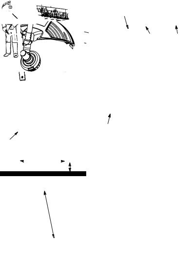
HARNESS
ADJUSTMENT
FOR BALANCE
15 cm |
|
|
|
below |
|
|
10 -- 30 cm |
waist |
|
|
above |
|
|
76 cm |
ground |
|
|
|
|
76 cm
ATTACHING THE SHIELD
 WARNING: The shield must be prop-
erly installed. The shield provides partial protection to the operator and others from the risk of thrown objects, and is equipped with a
line limiter blade which cuts excess line to the proper length. The line limiter blade (on underside of shield) is sharp and can cut you.
3. Secure shield to bracket with bolt.
Bolt
CONFIGURING YOUR UNIT
You can configure your unit using a cutting head
for grass and light weeds, or a weed blade for cutting grass, weeds, and brush up to 1 cm in diameter. To assemble your unit, go to the section for the desired configuration and follow the
instructions.
ASSEMBLY INFORMATION - TRIMMER HEAD
TRIMMER
HEAD
NOTE: Remove the blade before attaching the trimmer head. To remove blade, align hole in the dust cup with the hole in the side of the gearbox by rotating the blade. Insert a small screwdriver into aligned holes. This will keep the shaft from turning while loosening the blade nut. Remove blade nut by turning clockwise. Remove the screwdriver. Remove both washers and blade. See INSTALLATION OF THE METAL BLADE
for illustrations. Be sure to store all parts and instructions for future use. Never use the trimmer head with the metal blade installed.
7
 Loading...