MCC MMBD1503, MMBD1501, MMBD1504A, MMBD1503A, MMBD1501A Datasheet
...
M C C
omponents 21201 Itasca Street Chatsworth
! "# $% ! "#
Features
•Low Leakage
•Surface Mount Package Ideally Suited for Automatic Insertion
•150oC Junction Temperature
•High Conductance
Mechanical Data
•Case: SOT-23, Molded Plastic
•Terminals: Solderable per MIL-STD-202, Method 208
•Polarity: See Diagram
•Weight: 0.008 grams ( approx.)
Maximum Ratings @ 25oC Unless Otherwise Specified
Characteristic |
Symbol |
Value |
Unit |
|
Working Inverse Voltage |
VIV |
180 |
V |
|
DC Forward Current |
IF |
600 |
mA |
|
Average Rectified Current |
Io |
200 |
mA |
|
Recurrent Peak Forward Current |
if |
700 |
mA |
|
Peak Forward Surge Current @ t=1.0s |
if(surge) |
1.0 |
A |
|
@t=1.0ms |
2.0 |
|||
|
|
|||
|
|
|
|
|
Power Dissipation |
Pd |
350 |
mW |
|
Thermal Resistance |
R |
357 |
o C/W |
|
Operation & Storage Temp. Range |
Tj, TSTG |
-55 to +150 |
oC |
Note: 1) These ratings are based on a max. junction temperature of 150 degrees C 2) These are steady state limits. T he factory should be consulted on applications
involving pulsed or low duty cycle operation
Electrical Characteristics @ 25oC Unless Otherwise Specified
Charateristic |
Symbol |
Min |
Max |
Unit |
Test Cond. |
|
Breakdown Voltage |
BV |
200 |
|
V |
IR=5.0uA |
|
|
|
620 |
750 |
mV |
I F=1.0mA |
|
|
|
720 |
850 |
mV |
IF =10mA |
|
Forward Voltage Drop |
VF |
800 |
950 |
mV |
IF =50mA |
|
0.83 |
1.1 |
V |
IF =100mA |
|||
|
|
|||||
|
|
0.87 |
1.3 |
V |
IF =200mA |
|
|
|
0.9 |
1.5 |
V |
IF =300mA |
|
|
|
|
1.0 |
nA |
VR=125V |
|
Reverse Current |
IR |
----- |
3.0 |
uA |
VR =125V T A=150oC |
|
10 |
nA |
VR=180V |
||||
|
|
|
||||
|
|
|
5.0 |
uA |
VR =180V T A=150oC |
|
|
|
|
|
|
|
|
Junction Capacitance |
Cj |
----- |
4 |
pF |
VR =0V, f=1.0MHz |
MMBD1501(A)
THRU
MMBD1505(A)
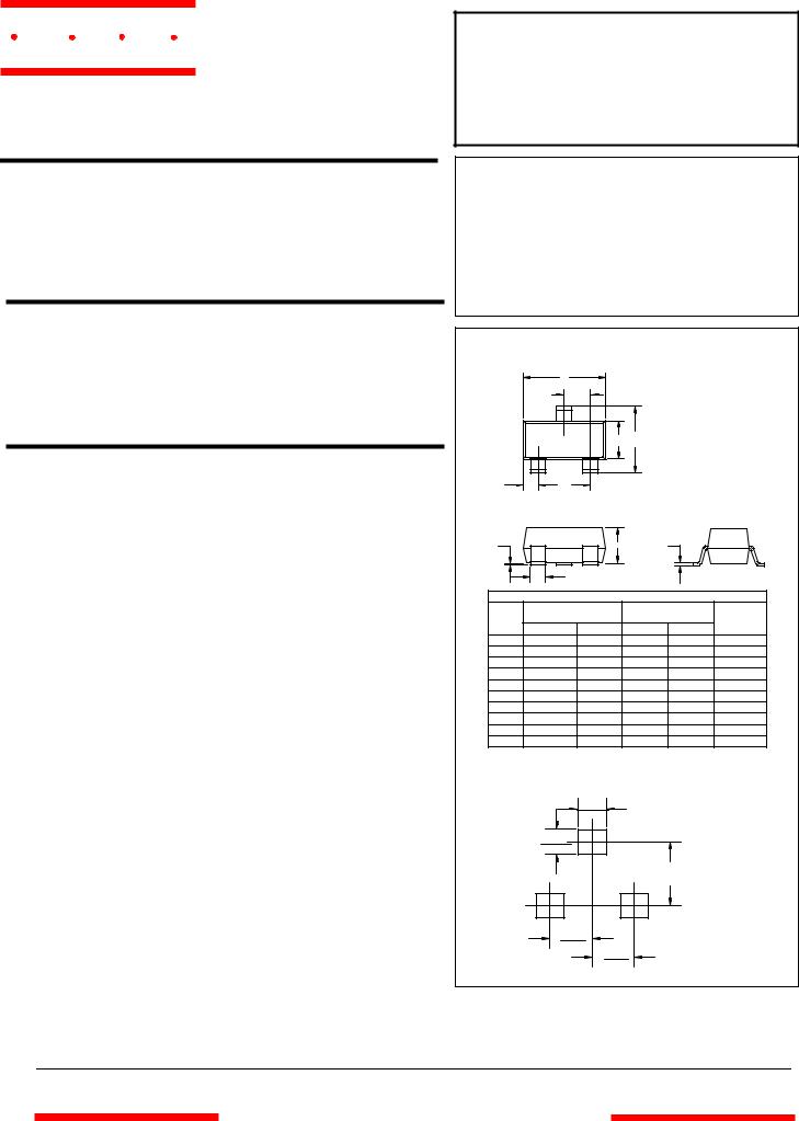
High Conductance
Low Leakage Diode
|
|
350mW |
|
|
|
|
|
SOT-23 |
|
|
|
|
A |
|
|
|
|
|
|
D |
|
|
|
|
|
C |
B |
|
|
F |
E |
|
|
|
|
G |
|
H |
J |
|
|
|
K |
|
|
|
|
|
|
DIMENSIONS |
|
|
|
|
INCHES |
|
MM |
|
|
DIM |
MIN |
MAX |
MIN |
MAX |
NOTE |
A |
.110 |
.120 |
2.80 |
3.04 |
|
B |
.083 |
.098 |
2.10 |
2.64 |
|
C |
.047 |
.055 |
1.20 |
1.40 |
|
D |
.035 |
.041 |
.89 |
1.03 |
|
E |
.070 |
.081 |
1.78 |
2.05 |
|
F |
.018 |
.024 |
.45 |
.60 |
|
G |
.0005 |
.0039 |
.013 |
.100 |
|
H |
.035 |
.044 |
.89 |
1.12 |
|
J |
.003 |
.007 |
.085 |
.180 |
|
K |
.015 |
.020 |
.37 |
.51 |
|
Suggested Solder
Pad Layout
.031
.800
.035
.900
.079 |
inches |
2.000 |
mm |
.037
.950
.037
.950
www.mccsemi.com
 Loading...