

Page 1

Model U-P1
(Machine Code: G071)
SERVICE MANUAL
Page 2

!IMPORTANT SAFETY NOTICES
PREVENTION OF PHYSICAL INJURY
1. Before disassembling or assembling parts of the printer and peripherals,
make sure that the printer power cord is unplugged.
2. The wall outlet should be near the printer and easily accessible.
3. If any adjustment or operation check has to be made with exterior covers off
or open while the main switch is turned on, keep hands away from electrified
or mechanically driven components.
4. The printer drives some of its components when it completes the warm-up
period. Be careful to keep hands aw ay from the mechani cal an d ele ctr i c al
components as the printer starts operation.
5. The inside and the metal parts of the fusing unit become extremely hot while
the printer is operating. Be careful to avoid touching those components with
your bare hands.
HEALTH SAFETY CONDITIONS
Toner and developer are non-toxic, but if you get either of them in your eyes by
accident, it may cause temporary eye discomfort. Try to remove with eye drops
or flush with water as first aid. If unsuccessful, get medical attention.
OBSERVANCE OF ELECTRICAL SAFETY STANDARDS
1. The printer and its peripherals must be serviced by a customer service
representative who has completed the training course on those models.
2. The NVRAM module (op tion) installed on the controller has a lithium battery
which can explode if replaced incorrectly. Replace the NVRAM only with an
identical one. The manufacturer recommends replacing the entire NVRAM.
Do not recharge or burn this battery. Used NVRAM must be handled in
accordance with local regulations.
SAFETY AND ECOLOGICAL NOTES FOR DISPOSAL
1. Do not incinerate toner bottles or used toner. Toner dust may ignite suddenly
when exposed to an open flame.
2. Dispose of used toner, the maintenance unit which includes developer or the
organic photoconductor in ac cordance with local regulations . (These are
non-toxic supplies.)
3. Dispose of replaced parts in accordance with local regulations.
When keepi ng used lithium batteries in order to dispose of them later, do not
put more than 100 batteries per sealed box. Storing larger numbers or not
sealing them apart may lead to chemical reactions and heat build-up.
4. When keeping used lith ium batteries in order to dispose of them later, do not
put more than 100 batteries per sealed box. Storing larger numbers or not
sealing them apart may lead to chemical reactions and heat build-up.
Page 3
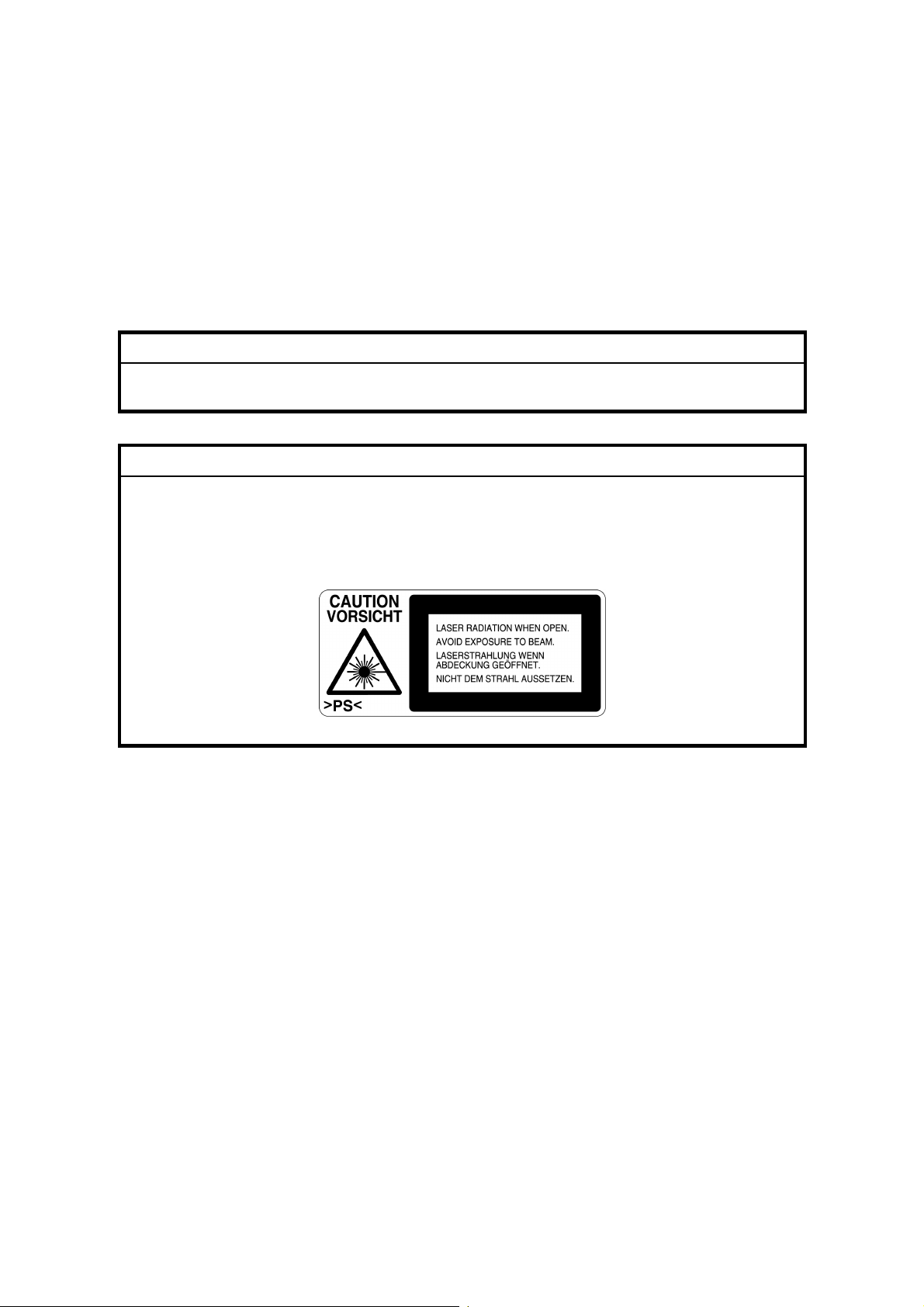
LASER SAFETY
The Center for Devices and Radiological Health (CDRH) prohibits the repair of
laser-based optical units in the field. The optical housing unit can only be repaired
in a factory or at a location with the requisite equipment. The laser subsystem is
replaceable in the field by a qualified Customer Engineer. The laser chassis is not
repairable in the field. Customer engineers are therefore directed to return all
chassis and laser subsystems to the factory or service depot when replacement of
the optical subsystem is required.
!WARNING
Use of controls, or adjustment, or performance of procedures other than
those specified in this manual may result in hazardous radiation exposure.
!WARNING
WARNING: Turn off the main switch before attempting any of the
procedures in the Laser Optics Housing Unit section. Laser
beams can seriously damage your eyes.
CAUTION MARKING:
Trademarks
Microsoft
®
, Windows®, and MS-DOS® are registered trademarks of Microsoft
Corporation in the United States and /or other countries.
PostScript
®
PCL
Ethernet
PowerPC
®
is a registered trademark of Adobe Systems, Incorporated.
is a registered trademark of Hewlett-Packard Company.
®
is a registered trademark of Xerox Corporation.
®
is a registered trademark of International Business Machines
Corporation.
Other product names used herein are for identification purposes only and may be
trademarks of their respective companies. We disclaim any and all rights involved
with those marks.
Page 4

Conventions in this Manual
This manual uses several symbols.
Symbol What it means
☛ Refer to section number
!
"
#
$%
&%
See Core Tech Manual for details
Screw
Connector
Clip ring
E-ring
Lengthwise, SEF (Short Edge Feed)
Sideways, LEF (Long Edge Feed)
Page 5

TABLE OF CONTENTS
1. INSTALLA TION...........................................................................1-1
1.1 INSTALLATION REQUIREMENTS...........................................................1-1
1.1.1 ENVIRONMENT .............................................................................. 1-1
1.1.2 MACHINE LEVEL............................................................................ 1-1
1.1.3 SPACE REQUIREMENTS............................................................... 1-2
1.1.4 POWER REQUIREMENTS.............................................................. 1-2
1.2 MACHINE INSTALLATION....................................................................... 1-3
1.3 OPTIONS.................................................................................................. 1-4
1.4 REMARKS FOR INSTALLATION............................................................. 1-5
2. PREVENTIVE MAINTENANCE...................................................2-1
2.1 OVERVIEW .............................................................................................. 2-1
Users Do the User PM Procedures...................................................... 2-1
All PM Done by Technicians................................................................ 2-1
Counters .............................................................................................. 2-1
2.2 USER MAINTENANCE............................................................................. 2-1
Main Unit.............................................................................................. 2-1
Optional Paper Tray Unit...................................................................... 2-2
2.3 SERVICE MAINTENANCE....................................................................... 2-2
Main Unit.............................................................................................. 2-2
Optional Units....................................................................................... 2-3
3. REPLACEMENT AND ADJUSTMENT........................................ 3-1
3.1 SPECIAL TOOLS................................................................................ 3-1
3.2 EXTERIOR COVERS............................................................................... 3-2
3.2.1 REAR COVER................................................................................. 3-2
3.2.2 LOWER LEFT COVER.................................................................... 3-3
3.2.3 UPPER COVER, OPERATION PANEL........................................... 3-3
3.3 ELECTRICAL COMPONENTS................................................................. 3-4
3.3.1 PRINTER CONTROLLER................................................................ 3-4
3.3.2 CONTROLLER BOX........................................................................ 3-4
3.3.3 BCU BOARD.................................................................................... 3-4
3.3.4 I/O BOARD...................................................................................... 3-5
3.3.5 PSU ................................................................................................. 3-5
3.3.6 HIGH VOLTAGE SUPPLY BOARD................................................. 3-6
3.4 DRIVE UNITS........................................................................................... 3-7
3.4.1 DEVELOPMENT CLUTCHES.......................................................... 3-7
K/Y Development Units........................................................................ 3-7
C/M Development Units....................................................................... 3-7
3.4.2 DEVELOPMENT MOTOR................................................................3-8
3.4.3 MAIN MOTOR.................................................................................. 3-8
3.4.4 PCU GEAR BOX AND OPC BELT CLEANING CLUTCH................ 3-9
3.4.5 FUSING UNIT MOTOR.................................................................... 3-9
3.4.6 PAPER FEED MOTOR.................................................................. 3-10
i
Page 6

3.4.7 PAPER FEED CLUTCH................................................................. 3-10
3.4.8 REGISTRATION CLUTCH............................................................. 3-10
3.5 LASER OPTICS SECTION..................................................................... 3-11
3.5.1 CAUTION DECAL LOCATION....................................................... 3-11
3.5.2 LASER OPTICS HOUSING UNIT.................................................. 3-12
Adjusting for Image Skew .................................................................. 3-14
Laser Beam Pitch Adjustment............................................................ 3-15
3.5.3 POLYGONAL MIRROR MOTOR AND LSD...................................3-16
3.6 DEVELOPMENT UNIT........................................................................... 3-17
3.7 PHOTOCONDUCTOR UNIT (PCU)........................................................ 3-19
3.7.1 MAIN UNIT..................................................................................... 3-19
3.7.2 WASTE TONER BOTTLES........................................................... 3-20
3.7.3 CHARGE CORONA WIRE............................................................. 3-21
3.7.4 CHARGE CORONA WIRE CLEANER MOTOR............................ 3-22
3.7.5 OPC BELT CLEANING UNIT......................................................... 3-22
3.7.6 IMAGE TRANSFER BELT CLEANING UNIT................................. 3-22
3.8 PAPER TRANSFER UNIT...................................................................... 3-23
3.8.1 VERTICAL TRANSPORT UNIT..................................................... 3-23
3.8.2 TRANSFER ROLLER.................................................................... 3-23
Cleaning the Paper Dust Mylar .......................................................... 3-24
3.9 FUSING/PAPER EXIT............................................................................ 3-25
3.9.1 FUSING UNIT................................................................................ 3-25
3.9.2 OIL SUPPLY UNIT......................................................................... 3-25
3.9.3 LAMPS........................................................................................... 3-26
3.9.4 FUSING INNER UNIT.................................................................... 3-27
3.9.5 PRESSURE ROLLER THERMOFUSE.......................................... 3-27
3.9.6 FUSING BELT UNIT AND PRESSURE ROLLER UNIT................ 3-27
3.9.7 PRESSURE ROLLER THERMISTOR........................................... 3-28
3.9.8 HOT ROLLER STRIPPERS........................................................... 3-28
3.9.9 PRESSURE ROLLER .................................................................... 3-29
3.9.10 OIL ABSORBERS........................................................................ 3-30
3.9.11 PAPER EXIT UNIT AND PAPER EXIT/
OVERFLOW SENSOR................................................................ 3-31
3.10 PAPER FEED AND TRANSPORT........................................................3-32
3.10.1 FEED ROLLER AND FRICTION PAD......................................... 3-32
3.10.2 REGISTRATION SENSOR.......................................................... 3-33
3.10.3 PAPER FEED SENSOR.............................................................. 3-35
3.10.4 PAPER NEAR-END SENSOR..................................................... 3-35
3.10.5 PAPER END SENSOR................................................................ 3-35
3.11 BYPASS TRAY..................................................................................... 3-36
3.11.1 PICKUP/FEED ROLLER.............................................................. 3-36
3.11.2 PAPER FEED CLUTCH............................................................... 3-37
3.11.3 REVERSE ROLLER .................................................................... 3-37
4. TROUBLESHOOTING.................................................................4-1
4.1 SERVICE CALL........................................................................................ 4-1
4.1.1 SERVICE CALL CONDITIONS........................................................ 4-1
4.1.2 SC TABLE........................................................................................ 4-2
ii
Page 7

4.2 CONTROLLER ERROR TABLE............................................................... 4-9
4.3 BLOWN FUSE CONDITIONS................................................................. 4-12
4.4 CHECK POINTS FOR IMAGE PROBLEMS AT REGULAR
INTERVALS............................................................................................ 4-12
5. SERVICE TABLES......................................................................5-1
5.1 SERVICE PROGRAM MODE................................................................... 5-1
5.1.1 OPERATION PANEL KEYS............................................................. 5-1
5.1.2 STARTING SERVICE PROGRAM MODE....................................... 5-2
Procedure 1.......................................................................................... 5-2
Procedure 2.......................................................................................... 5-2
5.1.3 MAIN MENU.................................................................................... 5-2
5.1.4 SPECIFYING A VALUE OR SETTING............................................ 5-3
5.1.5 LEAVING SERVICE MODE............................................................. 5-3
5.2 SP MODE TABLES................................................................................... 5-4
5.2.1 SERVICE (CONTROLLER SERVICE MODES)............................... 5-4
Bit Switch Settings ............................................................................... 5-6
Gamma Adjustment ............................................................................. 5-8
5.2.2 ENGINE SERVICE MODES.......................................................... 5-11
SP1-XXX: (Feed) ............................................................................... 5-11
SP2-XXX: (Drum)............................................................................... 5-15
SP3-XXX: (Process)........................................................................... 5-27
SP5-XXX: (Mode)............................................................................... 5-30
SP7-XXX: (Data Log)......................................................................... 5-38
Input Check Table.............................................................................. 5-46
Table 1: Tray 1 Paper Size ................................................................ 5-49
Table 2: 1st/2nd Bank Paper Size...................................................... 5-49
Table 3: 1st/2nd Bank Near End........................................................ 5-49
Output Check Table........................................................................... 5-50
5.3 CONTROLLER SELF-DIAGNOSTICS.................................................... 5-52
5.3.1 OVERVIEW.................................................................................... 5-52
5.3.2 DETAILED SELF-DIAGNOSTICS.................................................. 5-53
5.4 USER PROGRAM MODE....................................................................... 5-54
5.5 UPGRADING SOFTWARE..................................................................... 5-55
5.5.1 OVERVIEW.................................................................................... 5-55
5.5.2 UPGRADING................................................................................. 5-56
Procedure........................................................................................... 5-56
Error Recovery................................................................................... 5-57
5.6 DIP SWITCHES...................................................................................... 5-58
Controller Board................................................................................. 5-58
BCU Board......................................................................................... 5-58
5.7 PRINTING A TEST PATTERN ............................................................... 5-59
6. DETAILED SECTION DESCRIPTIONS.......................................6-1
6.1 OVERVIEW .............................................................................................. 6-1
6.1.1 MAJOR COMPONENTS.................................................................. 6-1
6.1.2 PAPER PATH.................................................................................. 6-2
6.1.3 DRIVE COMPONENTS................................................................... 6-3
iii
Page 8

v
6.1.4 ELECTRICAL COMPONENTS........................................................ 6-4
Image Transfer..................................................................................... 6-4
Development Units............................................................................... 6-5
Paper Path........................................................................................... 6-6
Drive Components............................................................................... 6-7
Circuit Boards....................................................................................... 6-8
6.2 PRINTING PROCESS OVERVIEW.......................................................... 6-9
6.3 PROCESS CONTROL............................................................................ 6-11
6.3.1 OVERVIEW.................................................................................... 6-11
6.3.2 PROCESS CONTROL STEPS...................................................... 6-12
Six Steps............................................................................................ 6-12
When is Process Control Done?........................................................ 6-12
6.4 PHOTOCONDUCTOR UNIT (PCU)........................................................ 6-13
6.4.1 OVERVIEW.................................................................................... 6-13
6.4.2 NEW PHOTOCONDUCTOR UNIT DETECTION........................... 6-14
New PCU Sensor............................................................................... 6-14
Mechanism......................................................................................... 6-14
PCU Counter...................................................................................... 6-14
6.4.3 CHARGE CORONA UNIT.............................................................. 6-15
Power Supply..................................................................................... 6-15
Wire Cleaning..................................................................................... 6-15
Cleaning Interval................................................................................ 6-15
Quenching.......................................................................................... 6-16
6.4.4 OPC BELT DRIVE......................................................................... 6-16
6.4.5 OPC BELT CLEANING UNIT......................................................... 6-17
Toner Collection Augers..................................................................... 6-17
Counter Blade + Brush....................................................................... 6-17
Waste Toner Bottle Sensors.............................................................. 6-17
Drive................................................................................................... 6-18
6.4.6 IMAGE TRANSFER BELT UNIT.................................................... 6-19
Drive................................................................................................... 6-19
Belt Mark Sensor................................................................................ 6-19
Bias Roller.......................................................................................... 6-20
6.4.7 TRANSFER BELT CLEANING UNIT............................................. 6-21
Bias Brush.......................................................................................... 6-21
Bias Roller and Cleaning Blade.......................................................... 6-21
Collecting Coil.................................................................................... 6-21
Waste Toner Bottle Sensors.............................................................. 6-21
Contact Mechanism ........................................................................... 6-22
Power Supply..................................................................................... 6-23
Drive................................................................................................... 6-23
6.5 LASER EXPOSURE............................................................................... 6-24
6.5.1 OVERVIEW.................................................................................... 6-24
Dust Shield Glass Cleaning ............................................................... 6-25
LD Unit Adjustment............................................................................ 6-25
Polygonal Mirror................................................................................. 6-25
Laser Diode Power Control................................................................ 6-25
Maintenance Adjustment.................................................................... 6-25
6.5.2 LD SAFETY SWITCH.................................................................... 6-26
i
Page 9

v
Operation Panel Message and Switch Mechanism............................ 6-27
6.6 DEVELOPMENT..................................................................................... 6-28
6.6.1 OVERVIEW.................................................................................... 6-28
6.6.2 DEVELOPMENT UNIT .................................................................. 6-29
Rollers and Agitators.......................................................................... 6-29
Replacing Units.................................................................................. 6-29
Memory Chip...................................................................................... 6-29
6.6.3 TONER SUPPLY MECHANISM.................................................... 6-30
Toner Cartridge Agitators................................................................... 6-30
Drive Power Path............................................................................... 6-30
Development Unit Agitator................................................................. 6-30
Toner Supply Roller and Doctor Roller............................................... 6-30
Shutter ............................................................................................... 6-30
6.6.4 TONER END DETECTION............................................................ 6-31
Mechanism......................................................................................... 6-31
Toner Near-End Detection................................................................. 6-31
Toner End Detection.......................................................................... 6-32
Toner End Recovery.......................................................................... 6-32
6.6.5 DEVELOPMENT UNIT CONTACT MECHANISM ......................... 6-33
Mechanism......................................................................................... 6-33
Reverse Rotation ............................................................................... 6-33
6.6.6 POWER SOURCE......................................................................... 6-34
Development, Toner Supply, and Doctor Rollers............................... 6-34
Doctor Roller...................................................................................... 6-34
6.7 PAPER FEED......................................................................................... 6-35
6.7.1 OVERVIEW.................................................................................... 6-35
Transport Speed................................................................................ 6-36
Friction Pad........................................................................................ 6-36
6.7.2 STANDARD TRAY DRIVE............................................................. 6-36
Feed and Vertical Transport Rollers................................................... 6-36
Registration Roller.............................................................................. 6-36
6.7.3 STANDARD TRAY – BOTTOM PLATE LIFT................................. 6-37
Lift Mechanism................................................................................... 6-37
Paper Near End Detection................................................................. 6-37
Paper End Detection.......................................................................... 6-37
6.7.4 STANDARD TRAY - PAPER SIZE DETECTION........................... 6-38
Mechanism......................................................................................... 6-38
Switch Pattern.................................................................................... 6-38
6.7.5 BYPASS TRAY.............................................................................. 6-39
Paper Feed Mechanism..................................................................... 6-39
Bypass Tray Drive Power Path .......................................................... 6-39
Pick-up Solenoid................................................................................ 6-39
Paper End Sensor.............................................................................. 6-39
6.8 PAPER TRANSFER AND SEPARATION............................................... 6-40
6.8.1 OVERVIEW.................................................................................... 6-40
Jammed Paper Release..................................................................... 6-40
Image Transfer and Paper Separati on............................................... 6-40
6.8.2 MECHANISM................................................................................. 6-41
Timing................................................................................................ 6-41
Page 10

Mechanism......................................................................................... 6-41
6.8.3 POWER SUPPLY.......................................................................... 6-42
Electric Power Path............................................................................ 6-42
Transfer Roller Bias ........................................................................... 6-42
Discharge Plate.................................................................................. 6-42
Temperature/Humidity Control........................................................... 6-42
Roller Cleaning................................................................................... 6-43
6.9 FUSING UNIT AND OIL SUPPLY UNIT................................................. 6-44
6.9.1 OVERVIEW.................................................................................... 6-44
6.9.2 FUSING UNIT CONFIGURATION................................................. 6-45
Fusing Belt......................................................................................... 6-45
Oil Supply........................................................................................... 6-45
Heating Roller Lamp .......................................................................... 6-45
Pressure Roller Lamp ........................................................................ 6-45
Pressure Roller Pawls ........................................................................ 6-45
Fusing Bias........................................................................................ 6-46
Fusing Unit SCs................................................................................. 6-46
6.9.3 TEMPERATURE CONTROL......................................................... 6-47
6.9.4 OIL SUPPLY AND CLEANING...................................................... 6-48
Oil Supply........................................................................................... 6-48
Oil Path.............................................................................................. 6-48
Oil Recycling...................................................................................... 6-48
Belt Cleaning...................................................................................... 6-48
Oil End Detection............................................................................... 6-49
Fusing unit switch............................................................................... 6-49
6.9.5 DRIVE............................................................................................ 6-49
Drive Power Path (Fusing Unit and Oil Supply Roller)....................... 6-49
Drive Power Path (Pressure Roller)................................................... 6-49
6.9.6 ENERGY SAVER MODE............................................................... 6-50
Level 1 Energy Saver Mode (default: off)........................................... 6-50
Level 2 Energy Saver Mode............................................................... 6-50
Ready Mode....................................................................................... 6-50
6.9.7 PAPER EXIT.................................................................................. 6-51
Drive Power Path............................................................................... 6-51
Paper Jam Detection.......................................................................... 6-51
6.9.8 OVERFLOW DETECTION............................................................. 6-51
6.10 PRINTED CIRCUIT BOARDS .............................................................. 6-52
6.10.1 PRINTER CONTROLLER............................................................ 6-52
Function............................................................................................. 6-52
Memory.............................................................................................. 6-52
Interfaces........................................................................................... 6-52
Slots................................................................................................... 6-53
Options............................................................................................... 6-53
DIP Switch.......................................................................................... 6-53
LED Indicators.................................................................................... 6-53
6.10.2 BASE ENGINE CONTROL UNIT (BCU)...................................... 6-54
Function............................................................................................. 6-54
Upgrading........................................................................................... 6-54
Nonvolatile Random Access Memory (NVRAM)................................ 6-54
vi
Page 11

DIP Switch.......................................................................................... 6-54
6.10.3 INPUT/OUTPUT (I/O) BOARD..................................................... 6-55
6.10.4 POWER SUPPLY UNIT (PSU).................................................... 6-55
6.10.5 HIGH VOLTAGE SUPPLY........................................................... 6-55
6.11 CONTROLLER..................................................................................... 6-56
6.11.1 OVERVIEW.................................................................................. 6-56
6.11.2 BOARD LAYOUT......................................................................... 6-58
6.11.3 PRINT DATA PROCESSING....................................................... 6-59
RPCS Driver....................................................................................... 6-59
PCL5c Driver...................................................................................... 6-59
PS3 Driver.......................................................................................... 6-60
CMS (Color Management System) .................................................... 6-60
Gray Correction.................................................................................. 6-60
BG/UCR (Black Generation/Under Color Removal)........................... 6-60
Gamma Correction............................................................................. 6-60
Toner Limitation................................................................................. 6-61
Dither Processing and ROP/RIP........................................................ 6-61
6.11.4 CONTROLLER FUNCTIONS....................................................... 6-62
Sample Print....................................................................................... 6-62
Locked Print....................................................................................... 6-62
Paper Source Selection ..................................................................... 6-63
Auto Continue.................................................................................... 6-64
Paper Output Tray.............................................................................. 6-65
Stapling.............................................................................................. 6-66
6.12 IEEE1394 INTERFACE........................................................................ 6-67
6.12.1 SPECIFICATIONS....................................................................... 6-67
Hardware Specification...................................................................... 6-67
System Requirements........................................................................ 6-67
6.12.2 IEEE1394..................................................................................... 6-67
6.12.3 BLOCK DIAGRAM....................................................................... 6-68
6.12.4 PIN ASSIGNMENT...................................................................... 6-68
6.12.5 REMARKS ABOUT THIS INTERFACE KIT................................. 6-69
6.12.6 TROUBLESHOOTING NOTES.................................................... 6-69
6.12.7 IP OVER IEEE 1394.................................................................... 6-70
6.13 IEEE 802.11B (WIRELESS LAN) ......................................................... 6-71
6.13.1 SPECIFICATIONS....................................................................... 6-71
6.13.2 BLOCK DIAGRAM....................................................................... 6-71
6.13.3 TRANSMISSION MODE.............................................................. 6-72
Ad hoc Mode...................................................................................... 6-72
Infrastructure Mode............................................................................ 6-72
6.13.4 SECURITY FEATURES............................................................... 6-73
Using the SSID in Ad hoc mode......................................................... 6-73
6.13.5 TROUBLESHOOTING NOTES.................................................... 6-74
Communication Status....................................................................... 6-74
Channel Settings................................................................................ 6-74
Troubleshooting Steps....................................................................... 6-75
6.14 USB ...................................................................................................... 6-76
6.14.1 SPECIFICATIONS....................................................................... 6-76
6.14.2 USB 1.1/2.0.................................................................................. 6-76
vii
Page 12

6.14.3 USB CONNECTORS................................................................... 6-77
6.14.4 PIN ASSIGNMENT...................................................................... 6-77
6.14.5 REMARKS................................................................................... 6-78
Related SP Mode............................................................................... 6-78
PERIPHERALS
PAPER TRAY UNIT (G313)
1. REPLACEMENT A N D ADJUSTMENT................................. G313-1
1.1 REAR COVER....................................................................................G313-1
1.2 PAPER FEED CLUTCH......................................................................G313-1
1.3 LIFT MOTOR......................................................................................G313-2
1.4 PAPER FEED MOTOR.......................................................................G313-2
1.5 CONTROLLER BOARD......................................................................G313-2
1.6 PICK-UP/FEED/SEPARATION ROLLERS.........................................G313-3
2. DETAILED DESCRIPTIONS ................................................ G313-4
2.1 MECHANICAL COMPONENT LAYOUT.............................................G313-4
Feed and Reverse Roller (FRR).....................................................G313-4
Drive Path......................................................................................G313-4
Paper End Feeler Method..............................................................G313-4
2.2 ELECTRICAL COMPONENT LAYOUT..............................................G313-5
2.3 DRIVE LAYOUT .................................................................................G313-6
2.4 PAPER SIZE DETECTION.................................................................G313-7
2.5 PAPER LIFT.......................................................................................G313-8
2.6 PAPER HEIGHT AND END DETECTION..........................................G313-9
Paper Height Detection..................................................................G313-9
Paper End Detection......................................................................G313-9
INTERCHANGE UNIT (G305)
1. REPLACEMENT A N D ADJUSTMENT................................. G305-1
1.1 EXTERIOR COVER AND PAPER EXIT SENSOR.............................G305-1
1.2 CONTROL BOARD.............................................................................G305-1
2. DETAILED DESCRIPTIONS ................................................ G305-2
2.1 ELECTRICAL COMPONENTS...........................................................G305-2
2.2 DRIVE.................................................................................................G305-2
2.3 MECHANISM......................................................................................G305-3
DUPLEX UNIT (G303)
1. REPLACEMENT A N D ADJUSTMENT................................. G303-1
1.1 EXTERIOR COVER............................................................................G303-1
1.2 ENTRANCE/EXIT SENSORS.............................................................G303-1
viii
Page 13

1.3 INVERTER MOTOR...........................................................................G303-2
1.4 CONTROLLER BOARD......................................................................G303-2
1.5 TRANSPORT MOTOR.......................................................................G303-2
2. DETAILED DESCRIPTIONS ................................................ G303-3
2.1 OVERVIEW ........................................................................................G303-3
2.2 ELECTRICAL COMPONENT LAYOUT..............................................G303-4
2.3 DRIVE LAYOUT .................................................................................G303-5
2.4 DUPLEX PAPER FEED ORDER........................................................G303-6
2.4.1 LONGER THAN A4/LT LEF .......................................................G303-6
2.4.2 UP TO A4/LT LEF......................................................................G303-7
2.5 REVERSE MECHANISM....................................................................G303-8
500-SHEET FINISHER (G314)
1. REPLACEMENT A N D ADJUSTMENT................................. G314-1
1.1 EXTERIOR COVERS.........................................................................G314-1
Front Cover....................................................................................G314-1
Rear Cover.....................................................................................G314-1
Lower Guide...................................................................................G314-2
Upper Cover...................................................................................G314-3
Right Cover....................................................................................G314-3
1.2 ENTRANCE UPPER GUIDE AND PAPER EXIT UNIT.......................G314-4
1.3 MOTORS............................................................................................G314-5
1.3.1 MAIN MOTOR............................................................................G314-5
1.3.2 JOGGER MOTOR .....................................................................G314-5
1.4 STAPLER ...........................................................................................G314-6
1.5 PADDLE ROLLER SOLENOID...........................................................G314-6
1.6 MAIN CONTROL PCB........................................................................G314-7
1.7 OUTPUT TRAY UNIT.........................................................................G314-8
2. DETAILED DESCRIPTIONS .............................................. G314-10
2.1 OVERALL MACHINE INFORMATION..............................................G314-10
2.1.1 COMPONENT LAYOUT..........................................................G314-10
2.1.2 DRIVE LAYOUT.......................................................................G314-11
2.1.3 ELECTRICAL COMPONENTS................................................G314-12
2.2 DETAILED SECTION DESCRIPTIONS............................................G314-14
2.2.1 OUTPUT TRAY........................................................................G314-14
Stack Height Detection.................................................................G314-14
Output Tray Up/Down Mechanism............................................... G314-15
2.2.2 PAPER FEED..........................................................................G314-16
Overview......................................................................................G314-16
Straight Feed-out Mode ...............................................................G314-16
Shift Sorting Mode........................................................................G314-17
Stapling Mode..............................................................................G314-19
2.2.3 JAM CONDITIONS..................................................................G314-20
2.2.4 ERROR DETECTION..............................................................G314-20
ix
Page 14

FOUR-BIN MAILBOX (G312)
1. REPLACEMENT A N D ADJUSTMENT................................. G312-1
1.1 EXTERIOR COVER............................................................................G312-1
1.2 MAIN MOTOR AND CONTROLLER BOARD.....................................G312-1
1.3 VERTICAL TRANSPORT AND PAPER OVERFLOW SENSORS...... G312-2
2. DETAILED DESCRIPTIONS ................................................ G312-3
2.1 OVERVIEW ........................................................................................G312-3
2.2 DRIVE.................................................................................................G312-4
Drive Path......................................................................................G312-4
2.3 ELECTRICAL COMPONENT LAYOUT..............................................G312-5
2.4 PAPER DISTRIBUTION.....................................................................G312-6
Mechanism.....................................................................................G312-6
Paper Overflow Sensor..................................................................G312-6
2.5 BASIC OPERATION...........................................................................G312-7
2.6 PAPER MISFEED DETECTION TIMING.............................................G312-7
SPECIFICATIONS
SPECIFICATIONS......................................................................Spec-1
1. GENERAL SPECIFICATIONS.............................................................. Spec-1
1.1 MAIN UNIT....................................................................................Spec-1
2. SUPPORTED PAPER SIZES............................................................... Spec-4
2.1 MAIN TRAY, BYPASS TRAY, AND DUPLEX UNIT ..................... Spec-4
2.2 FINISHER, MAIL BOX, AND PAPER TRAY UNIT........................ Spec-5
3. SOFTWARE ACCESSORIES...............................................................Spec-6
3.1 PRINTER DRIVERS..................................................................... Spec-6
3.2 UTILITY SOFTWARE...................................................................Spec-6
4. MACHINE CONFIGURATION.............................................................. Spec-7
4.1 SYSTEM COMPONENTS.............................................................Spec-7
Exterior........................................................................................... Spec-7
Interior............................................................................................ Spec-8
Maintenance Kits............................................................................Spec-8
4.2 OPTIONAL EQUIPMENT ............................................................. Spec-9
Paper Tray Unit.............................................................................. Spec-9
Finisher.......................................................................................... Spec-9
Mail Box....................................................................................... Spec-10
Duplex Unit...................................................................................Spec-10
Interchange Unit........................................................................... Spec-10
x
Page 15

21 August 2002 INSTALLATION REQUIREMENTS
1. INSTALLATION
1.1 INSTALLATION REQUIREMENTS
1.1.1 ENVIRONMENT
1. Temperature Range:
2. Humidity Range: 20% to 80% RH
3. Ambient Illumination: Less than 2,000 lux (keep the machine out of direct
4. Ventilation: 3 times/hr/person or more
5. Avoid exposing the machine to sudden temperature changes, which include:
1) Direct cool air from an air conditioner
2) Direct heat from a heater
6. Avoid installing the machine in areas that may be exposed to corrosive gas.
7. Install the machine at a location lower than 2,500 m (8,200 ft.) above sea level.
8. Install the machine on a strong, level base. (☛ 1.1.2)
9. Avoid installing the machine in areas that may be subjected to strong vibration.
10°C to 32°C (50°F to 89°F)
sunlight.)
Installation
1.1.2 MACHINE LEVEL
Front to back: Within 5 mm (0.2") of level
Right to left: Within 5 mm (0.2") of level
1-1
Page 16
INSTALLATION REQUIREMENTS 21 August 2002
A
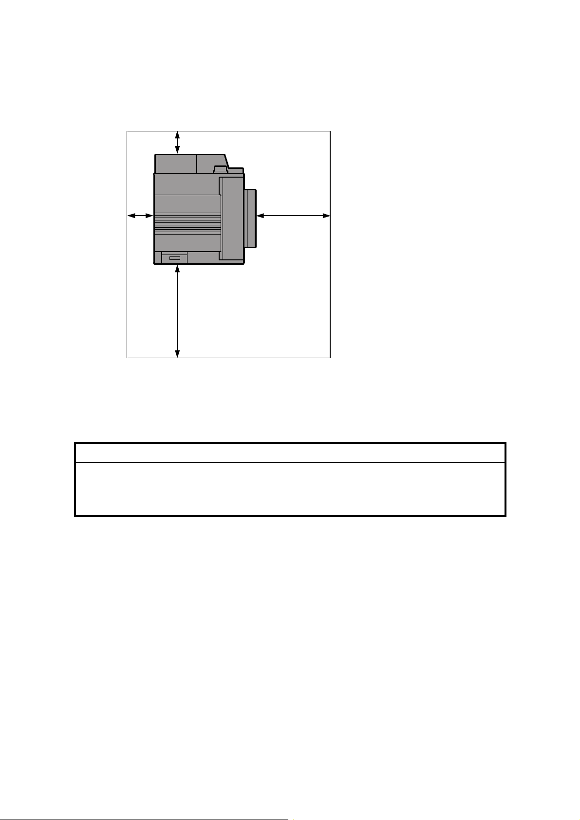
1.1.3 SPACE REQUIREMENTS
B
: Over 100 mm (4")
B: Over 100 mm (4")
A
C
C: Over 550 mm (22")
D: Over 750 mm (30")
D
G070I001.WMF
1.1.4 POWER REQUIREMENTS
!CAUTION
1. Insert the plug firmly in the outlet.
2. Avoid using an outlet extension plug or cord.
3. Ground the machine.
1. Input voltage level:
120 V, 60 Hz, More than 11 A
220 to 240 V, 50/60 Hz, More than 7 A
2. Permissible voltage fluctuation: ±10%
3. Do not put or place anything on the power cord.
1-2
Page 17

21 August 2002 MACHINE INSTALLATION
1.2 MACHINE INSTALLATION
Refer to the Operating Instructions for details.
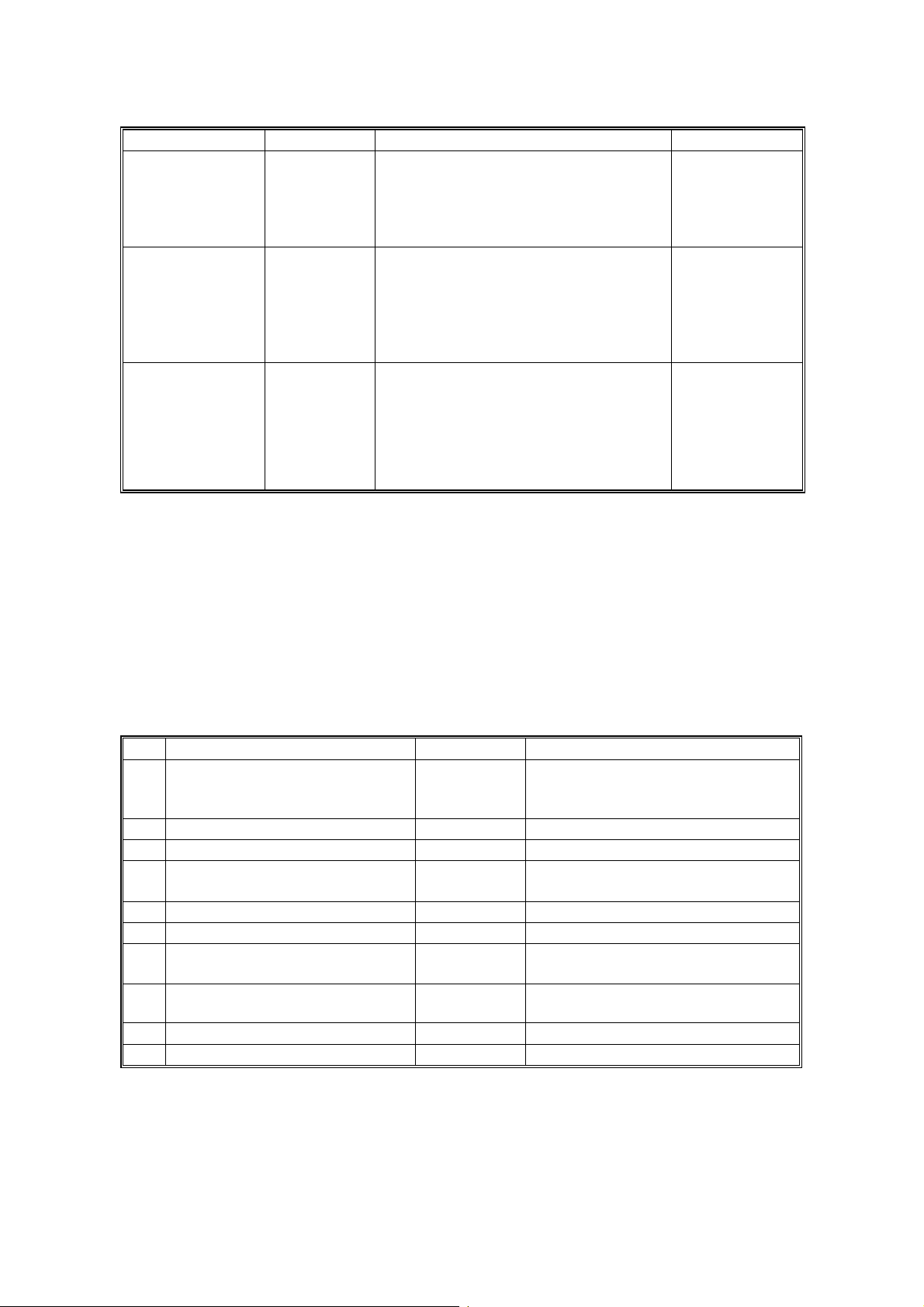
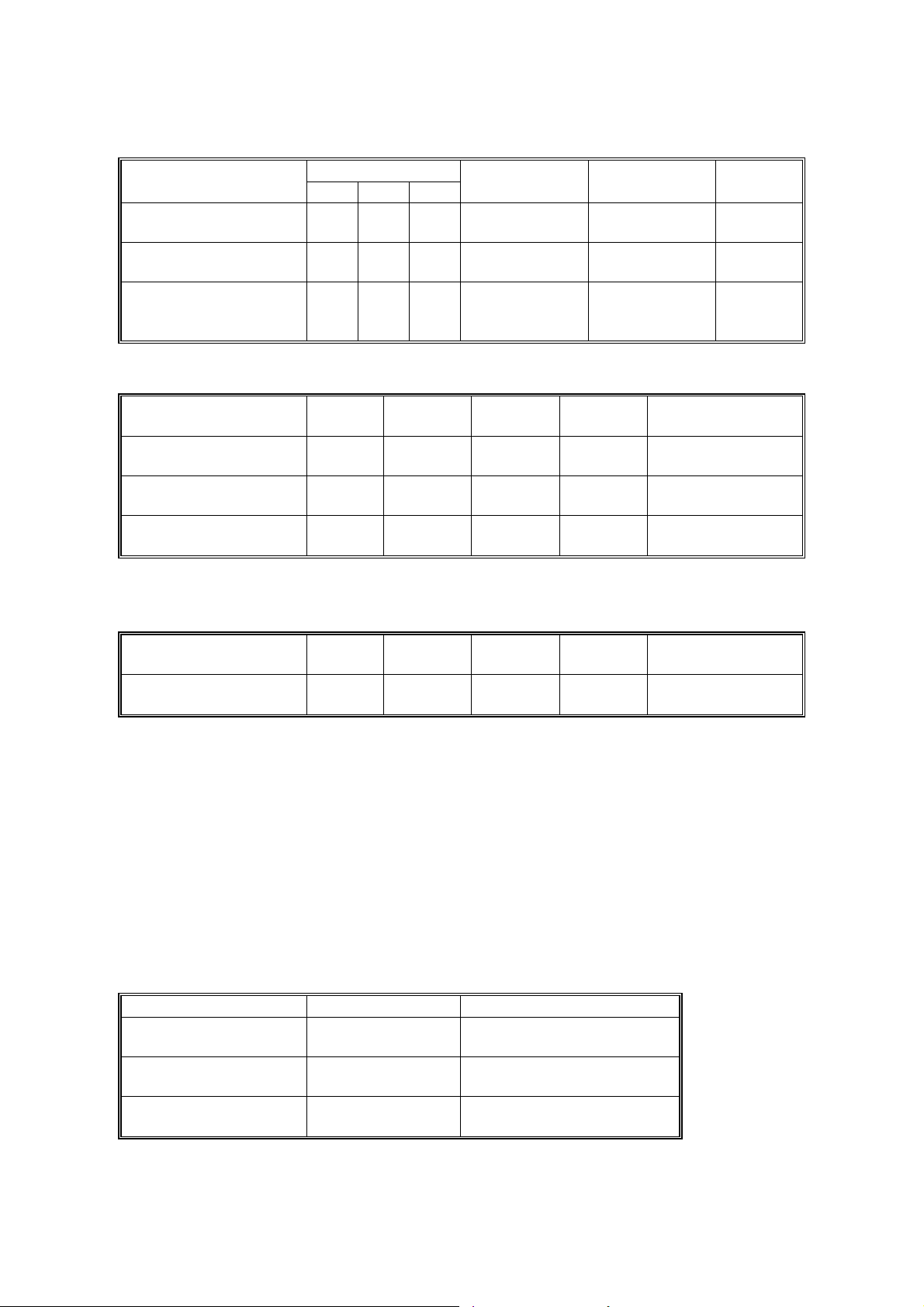
If the customer has a service contract, change the settings of the following SP
modes depending on the contract type.
Item SP No. Function Default
Meter charge SP5-930-1
(Meter_
Charge)
Counting method SP5-045-1
(Counter
Method)
A3/11" x 17"
double counting
SP5-104-1
(Double
Count)
PM warning
display 1
SP5-931-1
(PM_Display
– Charger)
PM warning
display 2
SP5-931-2
(PM_Display
– PCU)
Specifies whether the meter charge
mode is enabled or disabled.
If the user is doing the user PM
procedures, set meter charge to ‘O f f’.
If the technician is doing a ll t he PM,
set meter charge to ‘On’.
Meter charge mode enabled:
• The Counter menu appears
immediately after the Menu key is
pressed.
• The counter type selected by the
counting method (SP5-045-1,
Counter Method) can be displayed
with the Counter menu.
• The counter values can also be
printed with the Counter me nu.
• The selected counter starts fro m a
negative number.
Meter charge mode disabled:
• The Counter menu is not
displayed.
• The total counter starts from 0.
Specifies whether the counting
method used in meter charge mode is
based on developments or print s.
Important:
This SP can only be done bef ore the
negative counters are res et w ith SP7825-001 (Counter Reset)
Specifies whether the counter is
doubled for A3/11" x 17" paper.
Specifies whether the PM warning for
the charge corona unit is displayed
when the replacement time arrives.
1: Displayed
0: Not displayed
Specifies whether the PM warning for
the PCU is displayed.
1: Displayed
0: Not displayed
Off
Developments
No: Single
counting
1
1
Installation
1-3
Page 18
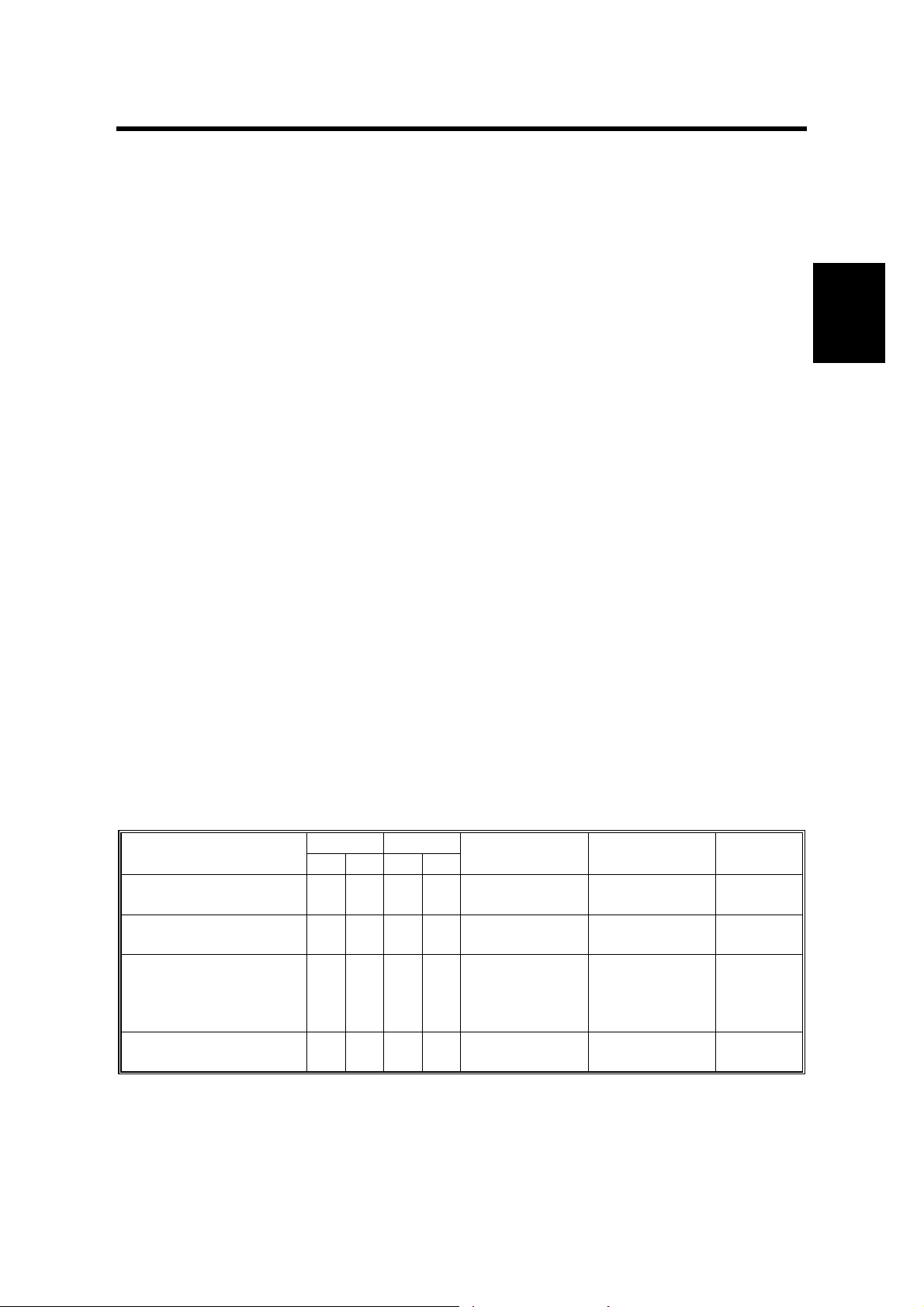
OPTIONS 21 August 2002
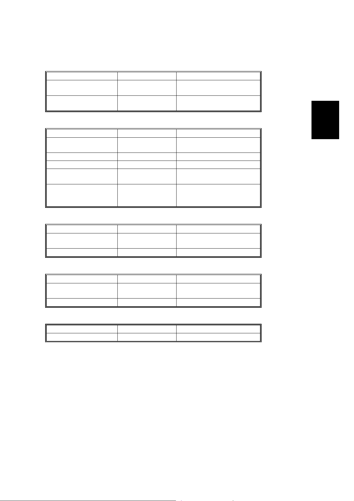
Item SP No. Function Default
PM warning
display 3
Fax No. setting SP5-812-2
Counter reset SP7-825-1
SP5-931-3
(PM_Display
- Bank_
Feed)
(FAX TEL
No.)
(Counter
Reset)
Specifies whether the PM warning for
the feed rollers in the optional paper
feed unit is displayed.
1: Displayed
0: Not displayed
Programs the service station fa x
number.
The number is printed on the cou nt er
list when the meter charge mode is
selected, so that the user can fax the
counter data to the service station.
Resets the counters to 0.
Important: Th is must be done at
installation after all the above settings
have been finished. The n egat ive
counters used in meter charge mode
will be reset to zero.
0
NOTE: 1) The default setting for this machine is meter-charge mode off.
2) The meter-charge counter cannot be reset.
1.3 OPTIONS
Refer to the Option Setup Guide for details.
No. Optional Unit Alternative Requirements
500-sheet finisher
1
2 4-bin mailbox No. 1
3 Interchange unit
Duplex unit
4
5 Paper tray unit
6 Printer hard disk
DIMM memory (64, 128, or 256
7
MB modules available)
IEEE1394 interface unit
8
9 User account enhance men t unit
10 IEEE802.11b (Wireless LAN)
No. 2
• No. 3
• Hard disk or memory (extra 64
MB or more) for sort mode
• No. 3
• No. 3
• Extra 64 MB (or more) optional
SDRAM module
NOTE: 1) You cannot install the finisher and mailbox on the same machine.
2) You can install either 1 or 2 paper tray units.
1-4
Page 19

21 August 2002 REMARKS FOR INSTALLATION
1.4 REMARKS FOR INSTALLATION
In case you install this printer or you instruct customers to install, please note the
following remark for development unit installation and replacement:
After installation or replacement of the development unit, print out the development
unit check sheet by user mode (User Mode – Maintenance – Development Unit
Check).
NOTE: For details please refer to the Quick Installation Guide.
Installation
1-5
Page 20
21 August 2002 OVERVIEW
2. PREVENTIVE MAINTENANCE
2.1 OVERVIEW
Users Do the User PM Procedures
The user does PM for the items in section 2.2. The technician does PM for the
items in section 2.3. Meter-charge mode must be set to “off” (SP5-930
[Meter_Charge], ☛ 5.2).
All PM Done by Technicians
The technician does PM for the items in sections 2.2 and 2.3. Meter-charge mode
must be set to “on” (SP5-930, [Meter_Charge], ☛ 5.2).
Counters
When a maintenance counter for a unit has reached the limit, the corresponding
message is displayed on the operation panel. After completing the maintenance
procedure for that item, reset the counter (SP7-804, [PM_Clear ], ☛ 5.2).
2.2 USER MAINTENANCE
Abbreviations:
C
lean, Inspect, Lubricate, Replace, KiloPrints, KiloDevelopments, WheneverNecessary
Preventive
Maintenance
Main Unit
Item
T/B waste toner bottle
O/B waste toner bottle
Oil supply unit
Fusing unit with paper
feed roller
* : Replacement period calculat ed for a 50% color ratio (the actual wast e t oner bottle condition
is detected with the sensors)
** : Standard replacement period (the actual oil amount is detected with the sen sor)
KD KP
50 120 30 120
R*
R*
R**
R
Waste toner
sensors
Waste toner
sensors
Oil end
sensor/Oil
supply unit
counter
Exit sheet
counter
Detection Reset
Auto-reset
(sensor)
Auto-reset
(sensor)
Manual reset
Manual reset
Machine
stops
Yes
Yes
Yes
Yes
2-1
Page 21
SERVICE MAINTENANCE 21 August 2002
Item
Black development unit
Color development unit
PCU (includes charge
corona unit & dust
filters)
*Displayed with SP7-906 (PMCounter-PREV)
60 120 240
KD
R
R
R
Item WN Detection Reset
Registration roller
Dust shield glass
(LD unit)
Bottom plate pad
C None None No
C None None No
C None None No
Optional Paper Tray Unit
Item 150KP Detection Reset
Feed, pick-up, and
separation rollers
R None None No
Detection Reset
Dev. Bk
counter*
Dev. color
counter*
PCU counter* Auto-reset (new
Auto-reset
(memory chip)
Auto-reset
(memory chip)
PCU sensor) No
Machine
stops
Machine
stops
Remarks
➀ damp cloth and
➁ dry cloth
Built-in cleaning
brush
➀ damp cloth and
➁ dry cloth
Remarks
➀ damp cloth and
➁ dry cloth
Machine
stops
Yes
Yes
2.3 SERVICE MAINTENANCE
Abbreviations:
C
lean, Inspect, Lubricate, Replace, KiloPrints, KiloDevelopments, WheneverNecessary
Main Unit
Bypass Tray
Item WN Remarks
Feed Roller
Pick-up Roller
Separation Roller
C
C
C
➀ damp cloth and
➁ dry cloth
➀ damp cloth and
➁ dry cloth
➀ damp cloth and
➁ dry cloth
2-2
Page 22
21 August 2002 SERVICE MAINTENANCE
Optional Units
Paper Tray Unit
Item WN Remarks
Relay Roller
Bottom Plate Pad
C
C
➀ damp cloth and
➁ dry cloth
➀ damp cloth and
➁ dry cloth
Finisher
Item WN Remarks
Rollers
C
➀ damp cloth and
➁ dry cloth
Sensors C Blower blush or dry cloth
Anti-Static Brush C Blower blush or dry cloth
Bushings
Stapler
L
R
Launa oil when abnormal
noise occurs
Every 200K staples
(estimated replacement
period)
Mail Box
Preventive
Maintenance
Item WN Remarks
Rollers
C
➀ damp cloth and
➁ dry cloth
Tray Paper Sensors C Blower blush or dry cloth
Duplex Unit
Item WN Remarks
Rollers
C
➀ damp cloth and
➁ dry cloth
Feed/exit sensors C Blower blush or dry cloth
Interchange Unit
Item WN Remarks
Paper Exit Sensor C Blower blush or dry cloth
2-3
Page 23

21 August 2002 SPECIAL TOOLS
3. REPLACEMENT AND ADJUSTMENT
!CAUTION
Turn off the main power switch and unplug the machine before beginning
any of the procedures in this section.
NOTE: This manual uses the following symbols.
☛ : See or Refer to ! : Screws " : Connector # : Clip ring
$ : E-ring
3.1 SPECIAL TOOLS
Part Number Part Name
N8036701 Flash Memory Card - 4MB
G0219350 Loop-back connector - Parallel
Adjustment
Replacement
3-1
Page 24
EXTERIOR COVERS 21 August 2002
3.2 EXTERIOR COVERS
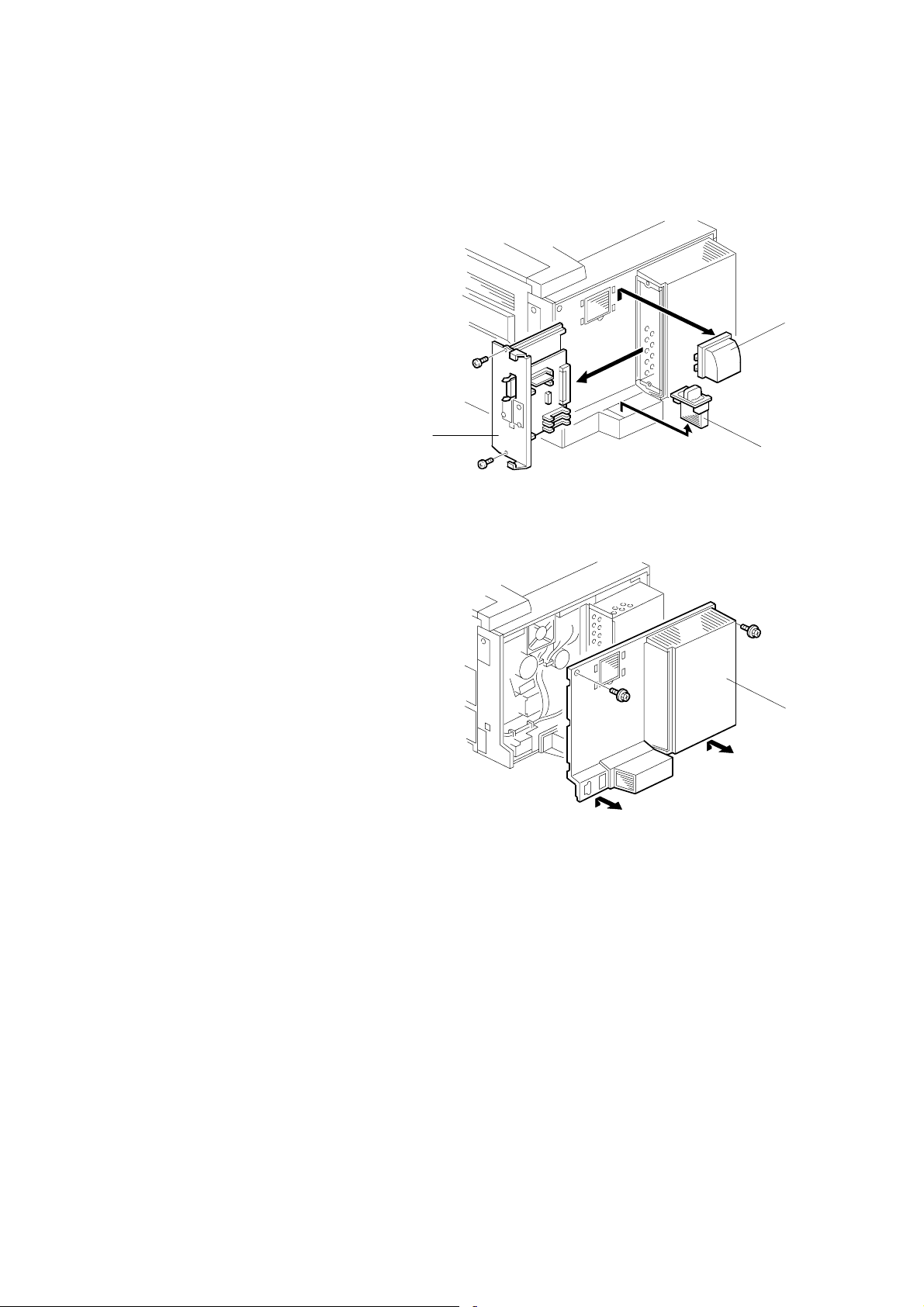
3.2.1 REAR COVER
1. Duct cover [A] (4 hooks)
2. Ozone filter [B]
3. Printer controller [C] (! x 2)
[C]
G070R702.WMF
[A]
[B]
4. Rear cover [D] (! x 2)
G070R703.WMF
[D]
3-2
Page 25
21 August 2002 EXTERIOR COVERS
3.2.2 LOWER LEFT COVER
1. Lower left cover [A] (! x 3)
[A]
3.2.3 UPPER COVER, OPERATION PANEL
1. Open the right cover [A].
2. Upper right cover [B]
3. Paper exit cover [C] (! x 1)
4. Open the front cover [D].
[F]
[E]
G070R704.WMF
Adjustment
Replacement
[C]
[B]
5. Upper cover [E] (! x 4)
6. Operation panel [F] (4 hooks,
" x 2, ! x 1)
NOTE: Insert a screwdriver between
the upper cover and the main
unit and unhook the panel.
[D]
G070R701.WMF
[A]
3-3
Page 26
ELECTRICAL COMPONENTS 21 August 2002
3.3 ELECTRICAL COMPONENTS
3.3.1 PRINTER CONTROLLER
☛ 3.2.1
NOTE: Remove the NVRAM from the old controller board, and install it on the new
one.
If the controller NVRAM is defective, reset the total counter to 0 after
changing the NVRAM, if meter charge mode is enabled.
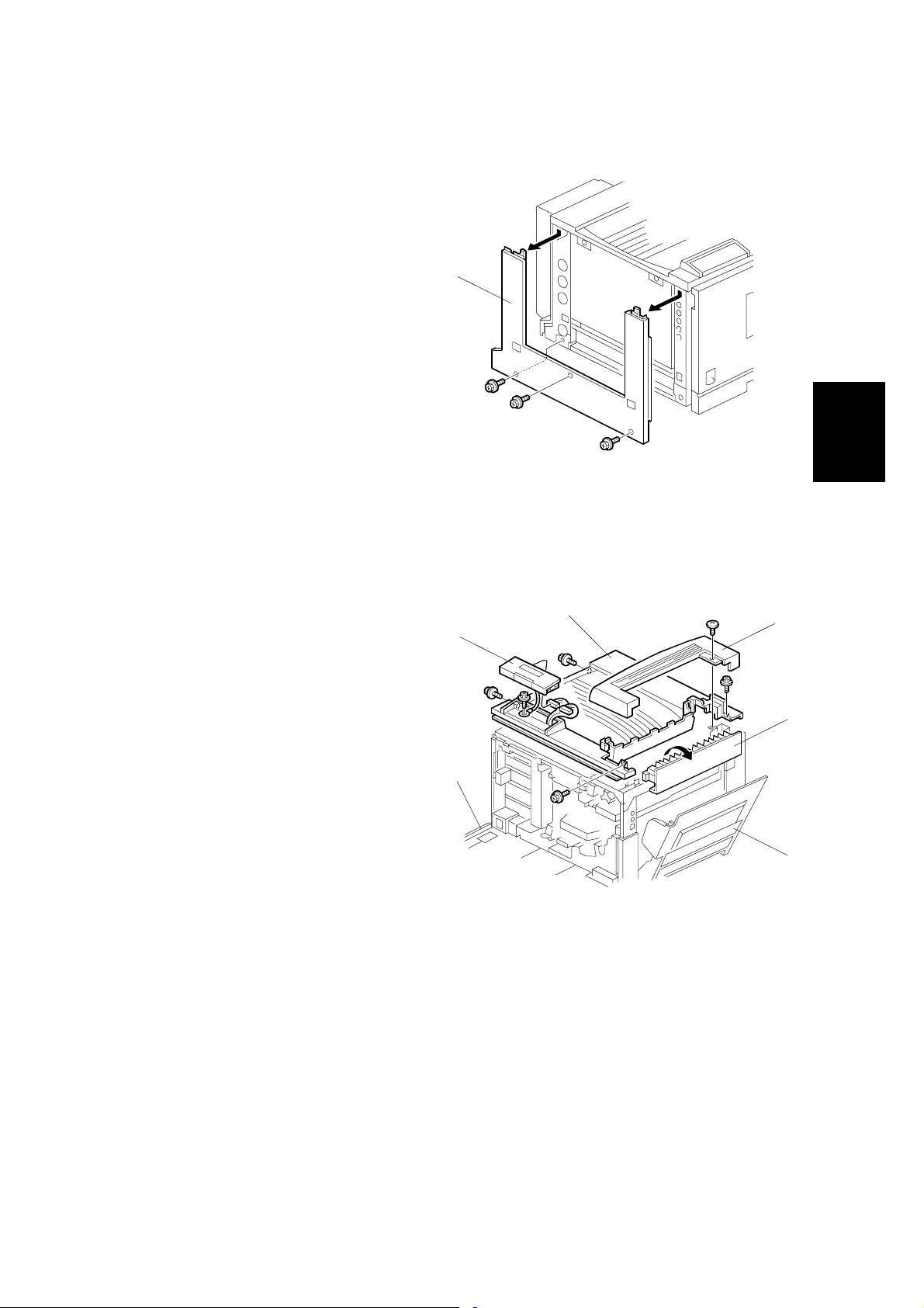
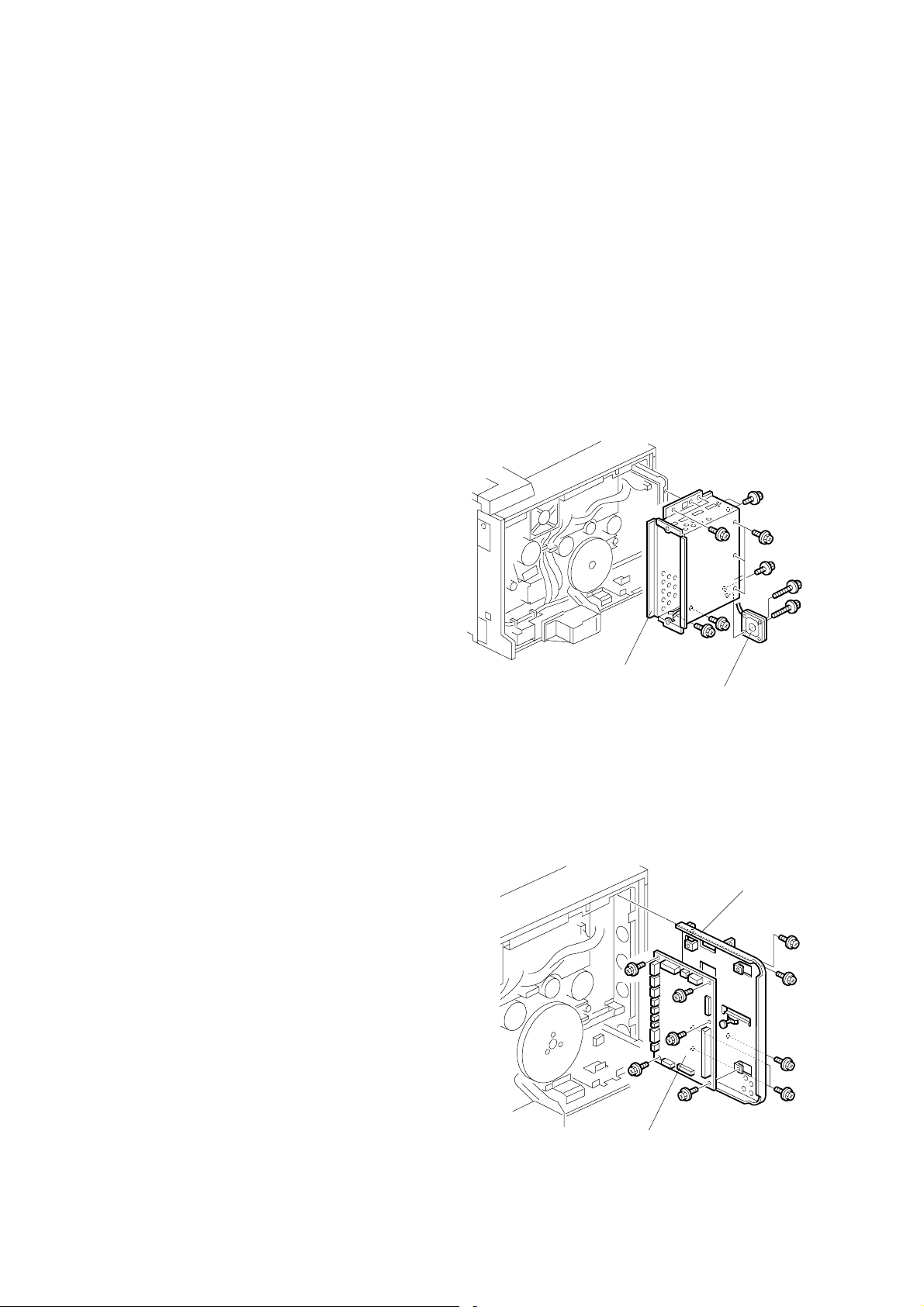
3.3.2 CONTROLLER BOX
1. Rear cover (☛ 3.2.1)
2. Cooling fan [A] (! x 2)
NOTE: When rea ssembling, install
the fan with the label
facing the inside.
3. Controller box [B] (! x 11)
NOTE: 1) Do not remove the
BCU board base with
the controller box.
2) When putting back
the controller box,
take care not to
pinch the cable from
the I/O board.
3.3.3 BCU BOARD
1. Controller box (☛ 3.3.2)
2. All " (12)
3. 1 flat cable
4. BCU board base [A] (! x 5)
5. BCU board [B] (! x 5)
NOTE: Remove the NVRAM from the old
BCU board, and install it on the
new one.
[B]
[B]
[A]
G070R705.WMF
[A]
G070R706.WMF
3-4
Page 27
21 August 2002 ELECTRICAL COMPONENTS
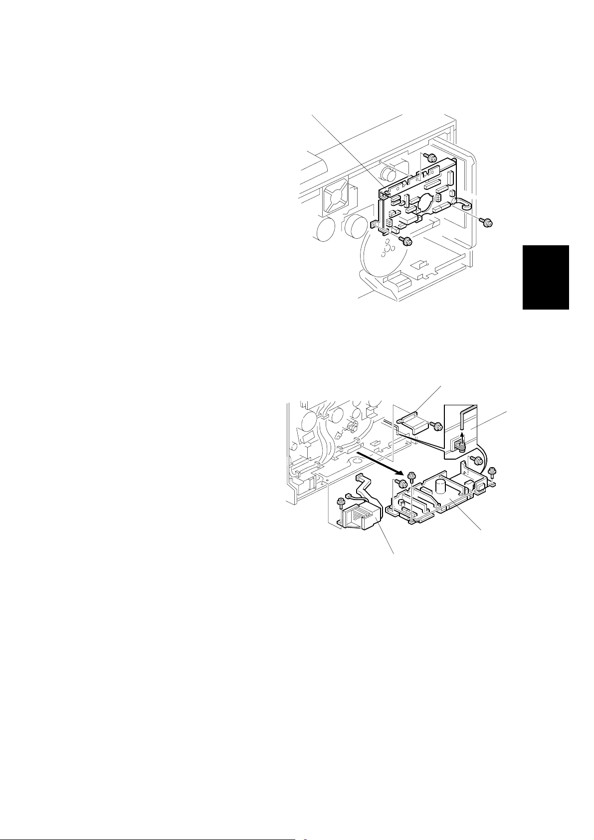
3.3.4 I/O BOARD
1. Controller box (☛ 3.3.2)
2. All " (33)
3. I/O board [A] (! x 4)
3.3.5 PSU
1. Controller box (☛ 3.3.2)
2. Flywheel (! x 3) (☛ 3.4.1)
[A]
G070R707.WMF
[B]
Adjustment
Replacement
[C]
3. Duct [A] (" x 1, ! x 1)
NOTE: When removing and
reassembling the fan,
install it with the label
facing the outside.
4. PSU protector [B] (! x 1)
5. Unlink the main switch [C].
6. PSU base (" x 8, ! x 4)
NOTE: 1) Remove the PSU [D]
with the PSU base.
2) When reas sem blin g,
check that the main
switch is linked to the
PSU.
[A]
[D]
G070R717.WMF
3-5
Page 28
ELECTRICAL COMPONENTS 21 August 2002
3.3.6 HIGH VOLTAGE SUPPLY BOARD
1. Photoconductor unit (☛ 3.7)
2. Right inner cover (☛ 3.10.2)
3. Photoconductor unit rail [A] (! x 2)
4. " [B] x 1
5. Bushing [C] x 1
[B]
[A]
G070R719.WMF
[C]
6. High voltage supply board [D] (" x 17,
! x 6)
[D]
G070R720.WMF
3-6
Page 29
21 August 2002 DRIVE UNITS
3.4 DRIVE UNITS
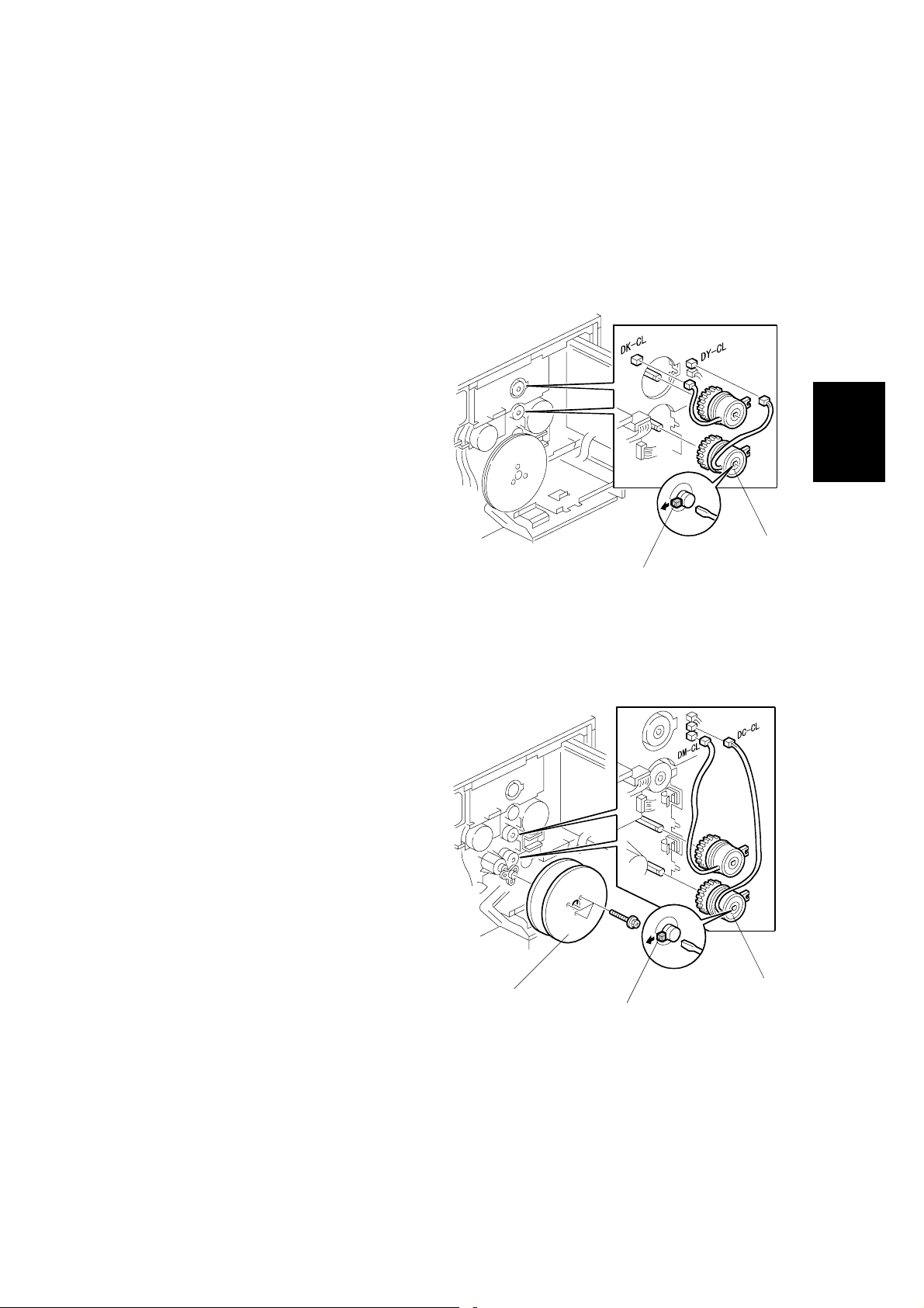
3.4.1 DEVELOPMENT CLUTCHES
1. Controller box (☛ 3.3.2)
K/Y Development Units
1. Unhook the lock [A] and pull out
the clutch [B] (" x 1).
C/M Development Units
1. Flywheel [A] (! x 3)
2. Unhook the lock [B] and pull out
the clutch [C] (" x 1).
[A]
[B]
G070R708.WMF
Adjustment
Replacement
3-7
[C]
[A]
[B]
G070R709.WMF
Page 30
DRIVE UNITS 21 August 2002
3.4.2 DEVELOPMENT MOTOR
1. Controller box (☛ 3.3.2)
2. Development motor [A] (" x 1,
! x 3)
[A]
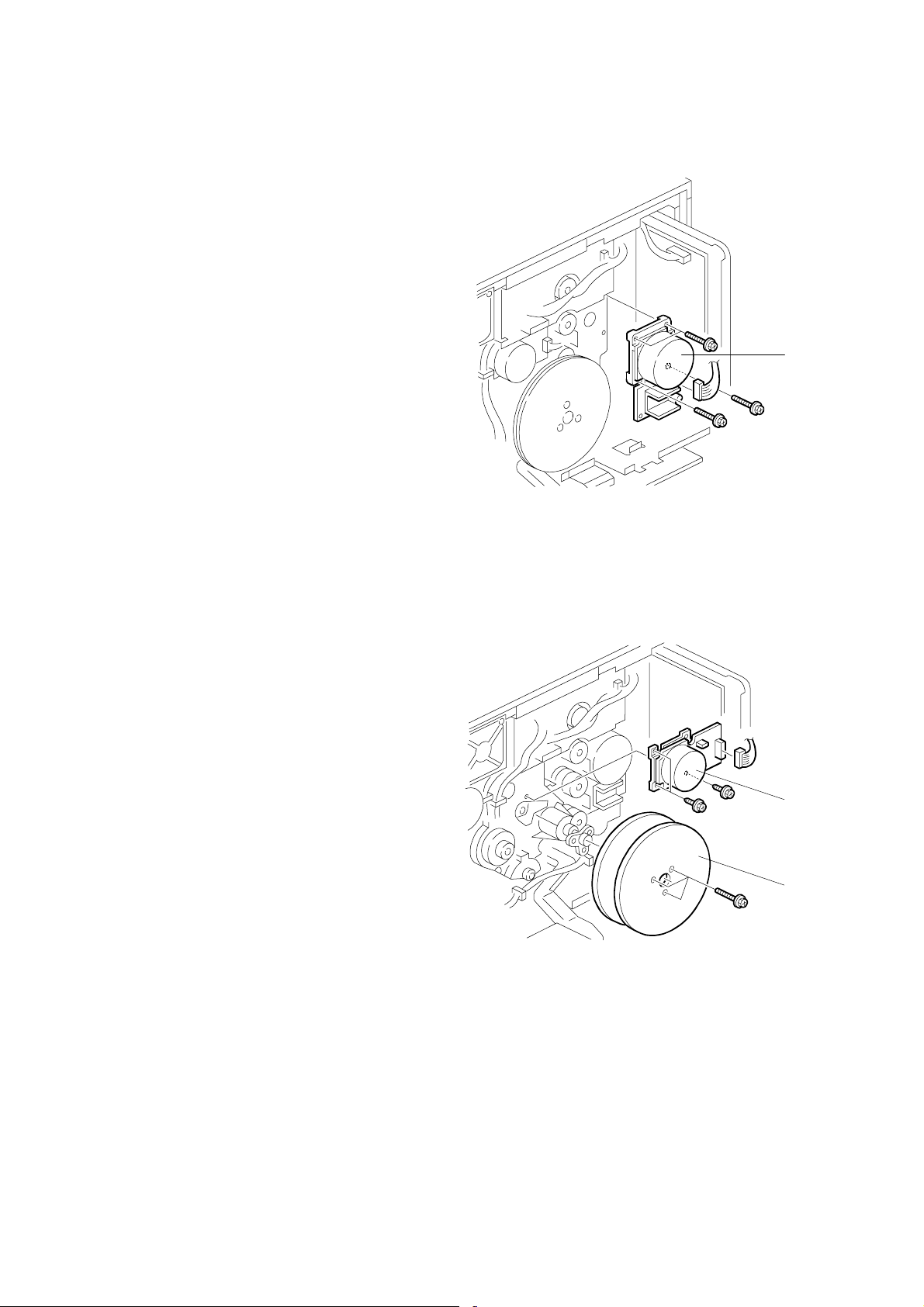
3.4.3 MAIN MOTOR
1. Controller box (☛ 3.3.2)
2. Flywheel [A] (! x 3)
3. Main motor [B] (" x 1, ! x 3)
G070R710.WMF
[B]
[A]
3-8
G070R711.WMF
Page 31

21 August 2002 DRIVE UNITS
3.4.4 PCU GEAR BOX AND OPC BELT CLEANING CLUTCH
1. I/O board (☛3.3.4 )
2. Main motor (☛ 3.4.3)
3. C/M development unit clutch
(☛ 3.4.1)
4. Bracket [A] (! x 2)
5. Tension spring [B]
6. " x 1 [C]
7. Gear box and clutch assembly
[D] (! x 5)
[A]
3.4.5 FUSING UNIT MOTOR
[C]
[B]
G070R712.WMF
[D]
Adjustment
Replacement
1. Rear cover (☛ 3.2.1)
2. Fusing unit motor (" x 1, ! x 3)
[A]
G070R713.WMF
[A]
3-9
Page 32

DRIVE UNITS 21 August 2002
3.4.6 PAPER FEED MOTOR
1. Rear cover (☛ 3.2.1)
2. Pull out the handle [A].
3. Paper feed motor [B] (" x 1,
! x 3)
[A]
3.4.7 PAPER FEED CLUTCH
1. Rear cover (☛ 3.2.1)
2. Pull out the handle [A].
3. Connector bracket [B] (" x 6,
! x 2)
4. Paper feed clutch [C] (" x 1,
[A]
! x 2)
3.4.8 REGISTRATION CLUTCH
[B]
G070R714.WMF
G070R716.WMF
[B]
[C]
1. Rear cover (☛ 3.2.1)
2. Unhook the lock [A] and pull the
clutch out [B] (" x 1).
3-10
[B]
[A]
G070R715.WMF
Page 33

21 August 2002 LASER OPTICS SECTION
3.5 LASER OPTICS SECTION
!WARNING
Turn off the main switch and unplug the machine before beginning any of
the procedures in this section. Laser beams can cause serious eye injury.
3.5.1 CAUTION DECAL LOCATION
Adjustment
Replacement
LD_CAUTION.TIF
G070R208.WMF
!DANGER
Turn off the main switch and disconnect the power plug from the power
outlet before beginning any disassembly or adjustment of the laser unit.
This printer uses a class-1 laser beam with a wavelength of 650 nm and an
output of 7 mW. The laser can cause serious eye injury.
3-11
Page 34

LASER OPTICS SECTION 21 August 2002
3.5.2 LASER OPTICS HOUSING UNIT
1. Open the left cover [A].
2. ID chip connectors [B] (" x 4)
3. Development units [C] x 4
4. Rear cover (
☛ 3.2.1)
5. Left cover [D]
6. Lower left cover [E] (! x 3)
[B]
[E]
[C]
[A]
G070R301.WMF
7. Controller box (☛ 3.3.2)
8. Flat cable [F]
NOTE: When reassembling,
connect the flat cable with
the blue side up.
9. " x 4 [G]
10. Harness clamps [H]
[G]
[D]
G070R201.WMF
[F]
[H]
3-12
G070R202.WMF
Page 35

21 August 2002 LASER OPTICS SECTION
11. Open the front cover.
12. Remove the dust shield glass
cleaner lever [A] from the dust
shield glass cleaner.
NOTE: The dust shield glass
cleaner lever is the blue
lever at the right side of the
main switch.
13. LD cover [B] (! x 2)
14. Laser optics housing unit [C]
(! x 4)
[A]
[B]
G070R209.WMF
Adjustment
Replacement
[C]
G070R203.WMF
3-13
Page 36

LASER OPTICS SECTION 21 August 2002
Adjusting for Image Skew
1. Positioning pin [A] (! x 1)
2. Loosen ! (x 4) [B].
3. Adjust the position of the laser
optics housing unit [☛ NOTE].
4. Fasten ! (x 4) [B].
NOTE: After changing the position
of the laser optics housing
unit, do not reinstall the
positioning pin. Keep the
pin in a safe place.
NOTE: When the image ske ws as
shown, move the unit 1 mm
in the direction of the black
arrow as shown in the upper
diagram.
1mm
[B]
[A]
[☛ NOTE]
G070R207.WMF
Paper feed
(A3 SEF)
G070R001.WMF
3-14
Page 37

21 August 2002 LASER OPTICS SECTION
Laser Beam Pitch Adjustment
1. Select test pattern 15 with
SP5-955-1 (Test Pattern –
Pattern).
2. Check if vertical black stripes
can be seen.
a) If stripes cannot be seen
(Figure 2), laser beam
pitch adjustment is not
required.
b) If stripes can be seen
(Figure 1), laser beam
pitch adjustment is
required. Go on to the
next step.
3. To adjust the laser beam pitch,
tighten or loosen the screw [A]
on the LD unit holder.
Feed direction
Figure 1 Figure 2
G070R952.WMF
[A]
Adjustment
Replacement
4. Set SP 2-917 (Test Pattern) to
‘On’. Then send a one-page
job to the printer, or print an
SMC list (SP 5-990-6, SP
Print mode – Non default).
5. Repeat steps 2 through 4 until
the black stripes disappear
(Figure 2).
G070R820.WMF
3-15
Page 38

LASER OPTICS SECTION 21 August 2002
3.5.3 POLYGONAL MIRROR MOTOR AND LSD
!WARNING
Do not touch any edges of the polygon mirror, spring, or bracket. These
edges can cause serious injury.
1. Development units, LD cover (☛ 3.5.2)
2. Cover [A] (! x 1)
NOTE: Before removing th e cover, clean
the cover to prevent toner from
entering into the unit.
3. Polygonal mirror motor [B]
(" x 1, ! x 4)
NOTE: Do not touch the surface.
of the polygonal motor.
4. Synch. detection board (LSD) [C]
(" x 1, ! x 1)
[C]
[B]
[A]
G070R204.WMF
3-16
G070R205.WMF
Page 39

21 August 2002 DEVELOPMENT UNIT
3.6 DEVELOPMENT UNIT
!CAUTION
Do not touch the development unit sleeves or ID chip terminals.
1. Open the left cover [A].
2. ID chip connector [B]
3. Lift up the development unit [C]
slightly, and pull it out of the
machine.
NOTE: Remove the units in the
order K, Y, C, M. For
example, before remov i ng
the M unit, remove the K, Y,
and C units first.
[B]
[C]
[A]
G070R301.WMF
Replacement
Adjustment
4. Peel off the toner cartridge seal [D].
5. Reinstall the toner cartridge in the
development unit.
6. Keep the development unit level and
shake the development unit about 10
times from side to side.
NOTE: 1) Do not touch the
development roller or the
development roller gear.
2) Use caution not to drop the
cartridge or to damage it.
3) If the cartridge has not been
shaken well, the machine
takes a longer time to
initialize the development
unit, or an error message or
SC350 is displayed. When
either of them is displayed,
turn the main switch off and
on.
[D]
G070R901.WMF
G070R902.WMF
3-17
Page 40

DEVELOPMENT UNIT 21 August 2002
7. Install the development unit in the
machine.
8. After installing the development
unit, print out the "development unit
check" sheet to confirm the correct
installation of the development unit
(Menu — Maintenance —
Devp.UnitCheck).
NOTE: A white line or band may
appear on one end of the
paper if a development is
incorrectly installed. To
correct this, pull out the
development unit partially
(about 30 mm) [E] and
slowly reinstall it.
[E]
G070R457.WMF
3-18
Page 41

21 August 2002 PHOTOCONDUCTOR UNIT (PCU)
3.7 PHOTOCONDUCTOR UNIT (PCU)
3.7.1 MAIN UNIT
NOTE: 1) Before replacing any of the parts or consumables in this section, cover
the floor with cloth or some sheets of paper.
2) Never tilt the unit. The toner may come out of the unit.
3) When handling the unit, grasp the brown (front) and green (top) grips.
Never touch the OPC (left) or transfer (right) belts.
4) After removing the photoconductor unit, cover it with a light-proof sheet.
Keep it in a dark place.
Adjustment
Replacement
[C]
1. Open the front cover [A].
2. Open the right cover [B].
3. ! x 4
[B]
[A]
G070R308.WMF
4. Pull the OPC unit [C] out of the machine.
5. Grasp the brown and green grips.
6. Lift the unit and remove it.
3-19
Page 42

PHOTOCONDUCTOR UNIT (PCU) 21 August 2002
3.7.2 WASTE TONER BOTTLES
1. O/B waste toner bottle [A]
2. T/B waste toner bottle [B]
[A]
[B]
G070R302.WMF
G070R303.WMF
3-20
Page 43

21 August 2002 PHOTOCONDUCTOR UNIT (PCU)
3.7.3 CHARGE CORONA WIRE
1. Modular cable [A]
2. Loosen ! (x 1) [B]
3. Charge corona unit [C]
4. Front bracket (! x 1) [D]
5. Grid [E]
6. Rear bracket [F]
[B]
[D]
[A]
[E]
[C]
G070R304.WMF
Adjustment
Replacement
[F]
7. Front wire cover [G]
8. Rear wire cover [H]
9. Wire cleaner [I]
10. Unhook the corona wire [J].
[G]
3-21
[H]
[J]
G070R305.WMF
G070R259.WMF
[I]
Page 44

PHOTOCONDUCTOR UNIT (PCU) 21 August 2002
3.7.4 CHARGE CORONA WIRE CLEANER MOTOR
1. Charge corona unit (☛ 3.7.3)
2. Front motor cover [A ] (! x 3)
3. Motor [B]
[A]
3.7.5 OPC BELT CLEANING UNIT
1. Photoconductor unit (☛ 3.7.1)
2. Charge corona unit (☛ 3.7.3)
3. Drive gear [A] (! x 1)
4. Rear brace [B] (! x 1)
5. Front brace [C] (! x 1)
6. OPC belt cleaning unit [D]
(! x 2)
NOTE: Hold up the
photoconductor unit while
removing the OPC belt
cleaning unit.
[A]
[B]
[B]
G070R306.WMF
[C]
G070R315.WMF
3.7.6 IMAGE TRANSFER BELT CLEANING UNIT
1. Photoconductor unit (☛ 3.7.1)
2. Bracket [A] (! x 2)
3. Image transfer belt cleaning unit
[B]
3-22
[B]
G070R309.WMF
[A]
Page 45

21 August 2002 PAPER TRANSFER UNIT
3.8 PAPER TRANSFER UNIT
3.8.1 VERTIC AL TRANSPORT UNIT
1. Open the right lower cover [A].
2. Right cover [B] (! x 1)
[A]
[B]
G070R451.WMF
Adjustment
Replacement
3.8.2 TRANSFER ROLLER
1. Brace [A] (! x 1)
2. Guide [B]
NOTE: To remove the screws,
turn the roller unit on its
pivot.
3. Transfer roller [C]
($ x 2, Bushing x 2, Bearing x 2)
[C]
[A]
[B]
G070R453.WMF
3-23
Page 46

PAPER TRANSFER UNIT 21 August 2002
Cleaning the Paper Dust Mylar
–Quick Method–
1. Cover [A]
2. Sweep away paper dust with a
blower brush [B].
–When the paper dust has to be removed completely–
1. Bracket [C] (! x 2)
[D]
2. Plate spring [D]
[E]
[C]
[B]
[A]
G070R562.WMF
3. Metal roller [E]
4. Bearing [F][G]
[G]
5. Spring [H][I]
6. Clean the mylar [J] with a dry cloth.
[I]
[F]
[H]
[J]
G070R561.WMF
3-24
Page 47

21 August 2002 FUSING/PAPER EXIT
3.9 FUSING/PAPER EXIT
!CAUTION
Turn off the main switch and wait until the fusing unit cools down before
beginning any of the procedures in this section. The fusing unit can cause
serious burns.
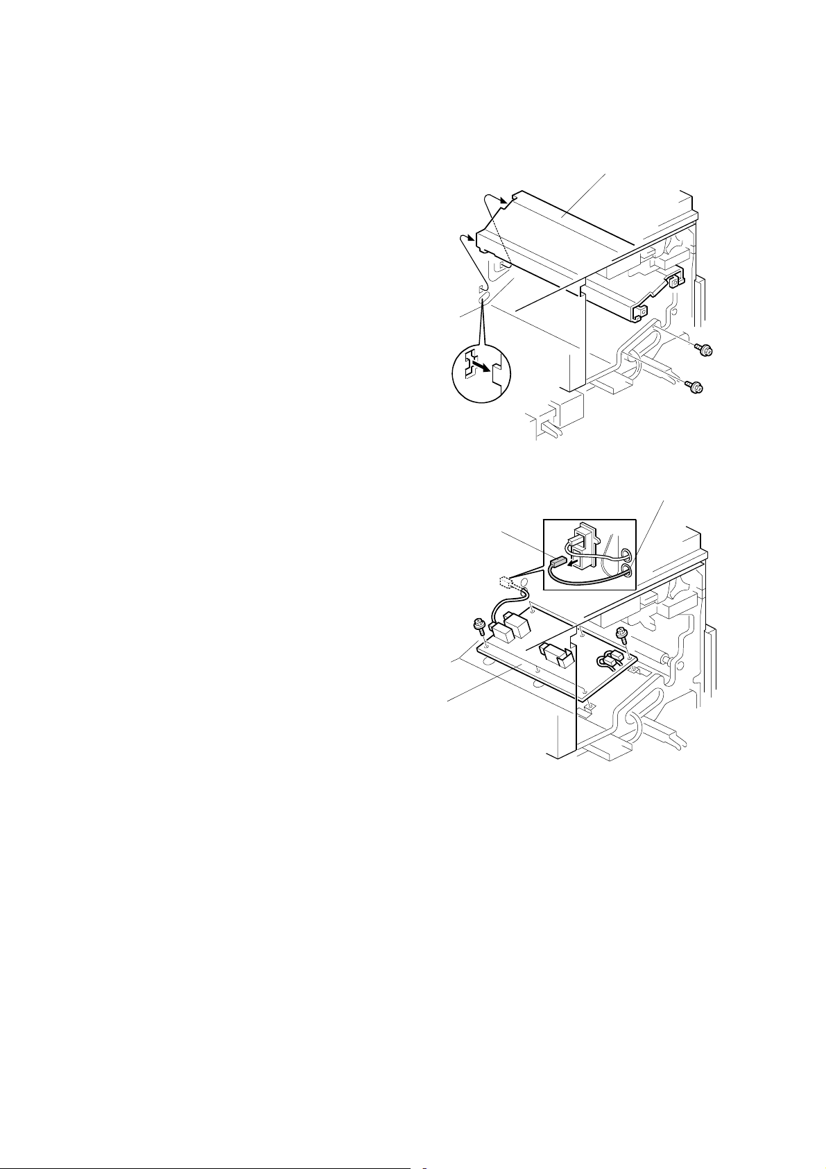
3.9.1 FUSING UNIT
[C]
1. Loosen the knob screw [A].
2. Pull the unit out of the machine.
3. Unhook the bottom stopper [B].
[D]
4. Grasp the rear end (marked with a
green label) [C].
5. Release the unit [D] from the base
plate [E].
3.9.2 OIL SUPPLY UNIT
NOTE: When removing eithe r of the
lamps (☛ 3.9.3), remove the
knob screw (☛ 3.9.1) before
removing the oil supply unit.
1. Fusing unit (☛ 3.9.1)
[A]
[B]
[A]
[E]
G070R501.WMF
Replacement
Adjustment
2. Put the fusing unit on a level place.
3. Oil supply unit [A]
NOTE: 1) Do not touch the oiling felt.
2) When reassembling, push the top of the oil supply unit so that the front
and rear hinges are correctly set.
G070R502.WMF
3-25
Page 48

FUSING/PAPER EXIT 21 August 2002
3.9.3 LAMPS
1. Oil supply unit (☛ 0)
2. Gear bracket [A] (! x 2)
3. Upper cover [B] (! x 2, shoulder
screw x 1)
4. Terminals [C], [D] (! x 5)
NOTE: [C]: Pressure roller lamp
terminals
[D]: Heating roller lamp
terminals
[D]
[B]
[C]
G070R503.WMF
[A]
[D]
5. Pull out the lamp (350 W) [E].
6. Pull out the lamp (770 W) [F].
NOTE: “350 W” and “770 W” are etched
on the respective terminals.
[H]
[F]
350W
G070R504.WMF
[E]
770W
G070R510.WMF
3-26
Page 49

21 August 2002 FUSING/PAPER EXIT
3.9.4 FUSI NG INNER UNIT
1. Lamps (☛ 3.9.3)
2. Drive gear [A]
3. Knob screw [B] ($ x 1)
4. Heating roller la mp harness terminal
[C] (! x 1)
5. Fusing inner unit [D] (! x 2,
" x 3)
[B]
3.9.5 PRESSURE ROLLER THERMOFUSE
1. Fusing inner unit (☛ 3.9.4)
2. Pressure roller thermofuse [A] (! x 2)
[D]
[A]
G070R506.WMF
[C]
[A]
Replacement
Adjustment
G070R508.WMF
3.9.6 FUSING BELT UNIT AND PRESSURE ROLLER UNIT
1. Fusing inner unit (☛ 3.9.4)
2. Springs [A] [B]
3. Separate the fusing belt unit [C] and
pressure roller unit [D ].
[A]
[C]
[D]
G070R507.WMF
[B]
3-27
Page 50

FUSING/PAPER EXIT 21 August 2002
3.9.7 PRESSURE ROLLER THERMISTOR
1. Pressure roller unit (☛ 3.9.6)
2. Pressure roller lower sta y [A ]
(! x 2)
3. Pressure roller thermistor
holder [B] (! x 1)
4. Pressure roller thermistor [C]
[C]
[B]
3.9.8 HOT ROLLER STRIPPERS
1. Oil supply unit (☛ 3.9.2)
2. Fusing lamps (☛ 3.9.3)
3. Fusing inner unit (☛ 3.9.4)
4. Gear [A]
NOTE: Remove the gear before
removing the stripper pawl
assembly; otherwise, the
gear may be damaged.
5. Hot roller stripper pawl assembly [B]
(Spring x 1, ! x 2)
[F]
[D]
[E]
[A]
G070R509.WMF
[B] [C]
[A]
6. Hot roller stripper pawl [C]
Reassembling
1. Put the spring [D] on the pawl.
2. Put the left end of the pawl in the square opening [E].
3. Put the front and rear ends of the pawl in the holder [F].
4. Confirm that the pawl moves correctly.
3-28
G070R552.WMF
Page 51

21 August 2002 FUSING/PAPER EXIT
3.9.9 PRESSURE ROLLER
[B]
[C]
[D]
1. Pressure roller un it (☛ 3.9.6)
2. Gear [A]
[E]
G070R900.WMF
[A]
Adjustment
Replacement
3. Hot roller stripper assembly [B] (! x 2)
4. Front bracket [C] (! x 1)
5. Bearing [D]
6. Pressure roller [E]
3-29
Page 52

FUSING/PAPER EXIT 21 August 2002
3.9.10 OIL ABSORBERS
[A]
[C]
G070R516.WMF
[G]
[L]
[K]
[J]
[I]
1. Fusing inner unit (☛ 3.9.4)
2. Absorber 1 [A]
3. Pressure roller un it (☛ 3.9.6)
4. Absorber holder [B] (! x 1)
[H]
[F]
[D]
[B]
[E]
G070R825.WMF
5. Absorber 2 [C]
6. Spring [D]
7. Absorber holder [E] (! x 1)
8. Absorber 3 [F]
9. Spring [G]
10. Base bracket [H] (! x 2)
11. Absorber holder [I] (! x 1)
12. Absorber 4 [J]
13. Absorber 5 [K]
14. Absorber 6 [L]
3-30
Page 53

21 August 2002 FUSING/PAPER EXIT
3.9.11 PAPER EXIT UNIT AND PAPER EXIT/OVERFLOW SENSOR
!CAUTION
Turn off the main switch and wait until the paper exit unit cools down
before beginning any of the procedures in this section. The paper exit unit
can cause serious burns.
1. Paper exit cover (☛ 3.2.3)
2. Paper exit unit [A] (" x 3,
! x 1)
NOTE: Remove 2 connectors
before removing the unit.
To remove the last
connector, remove the
unit and turn it. The
connector is on the
bottom side.
3. Paper exit sensor [B]
4. Paper overflow sensor [C]
[C]
[B]
[A]
G070R601.WMF
Replacement
Adjustment
3-31
Page 54

PAPER FEED AND TRANSPORT 21 August 2002
3.10 PAPER FEED AND TRANSPORT
3.10.1 FEED ROLLER AND FRICTION PAD
1. Paper tray [A]
[A]
2. # x 1 [B]
3. Slide the shaft [C].
4. Feed roller [D] (1 hook)
5. Friction pad [E]
[B]
[D]
[E]
G070R101.WMF
G070R102.WMF
[C]
3-32
Page 55

21 August 2002 PAPER FEED AND TRANSPORT
3.10.2 REGISTRATION SENSOR
1. Front cover [A] (L-shaped-pin x 2)
2. Rear cover (☛ 3.2.1)
3. Upper cover (☛ 3.2.3)
4. Lower left cover (☛ 3.5.2)
5. Dust shield glass cleaning lever [B]
(☛ 3.5.2)
6. Charge corona unit (☛ 3.7.3)
7. Right cover (☛ 3.8.1)
8. Left inner cover door [C]
9. Left inner cover [D] (! x 2)
10. Right inner cover [E] (! x 3)
[C]
[B]
[D]
[A]
[E]
G070R103.WMF
G070R653.WMF
Adjustment
Replacement
3-33
Page 56

PAPER FEED AND TRANSPORT 21 August 2002
11. Terminal [A] (! x 1)
NOTE: You have to remove the
terminal to lift the
transport stay (☛ step
14).
12. Transport guide [B] (! x 1)
[B]
G070R104.WMF
[A]
13. Drive gear [C] (1 hook)
14. Lift the transport stay [D] (! x 2)
and release the wire [E].
NOTE: You can see the wire clip
from the rear of the
machine.
15. Registration sensor [F] (" x 1,
! x 1)
[E]
[D]
[F]
[C]
G070R105.WMF
3-34
Page 57

21 August 2002 PAPER FEED AND TRANSPORT
3.10.3 PAPER FEED SENSOR
1. Lift the transport stay [A]
(☛ 3.10.2)
2. Paper feed sensor [B] (" x 1)
NOTE: Unhook the rear two pawls
first, move the feeler, and
unhook the front pawl.
3.10.4 PAPER NEAR-END SENSOR
1. Lift the transport stay [A] (☛ 3.10.2)
2. Feeler [B]
3. Sensor bracket [C] (! x 1)
4. Paper near-end sensor [D] (" x 1)
3.10.5 PAPER END SENSOR
[A]
[B]
[A]
[C]
G070R106.WMF
[D]
G070R107.WMF
[B]
Adjustment
Replacement
1. Lift the transport stay [A] (☛ 3.10.2)
2. Feeler [B]
3. Sensor bracket [C] (! x 2)
4. Paper end sensor [D] (" x 1)
3-35
[D]
[C]
[A]
[B]
G070R108.WMF
Page 58

BYPASS TRAY 21 August 2002
3.11 BYPASS TRAY
3.11.1 PICKUP/FEED ROLLER
1. Bypass tray (! x 3)
2. Upper cover [A] (! x 3)
[A]
3. Lift the paper end sensor feeler
[B].
4. Pick-up roller [C] (1 hook)
5. Paper feed roller [D] (# x 1)
[D]
[B]
G070R151.WMF
[C]
G070R152.WMF
3-36
Page 59

21 August 2002 BYPASS TRAY
3.11.2 PAPER FEED CLUTCH
1. Upper cover (☛ 3.11.1)
2. Rear cover [A] (! x 1)
3. Gear holder [B] ($ x 3)
4. Gears [C][D]
5. Clutch [E] (" x 1)
[A]
[C]
G070R153.WMF
[E]
[D]
[B]
Adjustment
Replacement
3.11.3 REVERSE ROLLER
1. Bypass tray (☛ 3.11.1)
2. Turn the unit upside down.
3. Bottom cover [A] (! x 3)
4. Reverse roller [B] (# x 1)
Bottom of unit
Top of unit
[A]
G070R154.WMF
3-37
[B]
G070R155.WMF
Page 60

21 August 2002 SERVICE CALL
4. TROUBLESHOOTING
4.1 SERVICE CALL
4.1.1 SERVI CE CALL CONDITIONS
Level Definition Reset Procedure
Fusing unit SCs displayed on the operation
panel. The machine is d isabled. The user
A
B
C
D
cannot reset the SC.
SCs that disable only t he features t hat use the
defective item. Although t hese SCs are not
shown to the user under normal cond it ions,
they are displayed on the operat ion panel only
when the defective featur e is selected.
SCs that are not shown on the operat ion panel.
They are internally logged.
Turning the operation switch or main power
switch off then on resets the SC. The SC is
displayed on the operat ion panel. It is
redisplayed if it occurs after the ma in power
switch is turned on again.
NOTE: 1) All SCs are logged.
2) When an electrical circuit board has a problem , check the connections
before replacing the PCBs.
3) When a motor has a problem, check the mechanical loa d before
replacing the motor or sensor.
Turn the main switch off then on
before entering SP mode. Reset
the SC (set SP5-810
[SC_Reset] to 1), then turn the
main switch off then on ag ain.
Turn the main power switc h of f
and on.
Logging only
Turn the main power switc h of f
and on.
Trouble-
shooting
4-1
Page 61

SERVICE CALL 21 August 2002
4.1.2 SC TABLE
No.
Definition
Symptom Possible Cause
Polygon motor error 201 D
• The polygon motor starts operating. → The lock signal
is not detected within 20 seconds.
• The polygon motor starts operating. → The lock signal
is detected within 20 seconds . → After a 3-second
waiting time, no lock signal is detected within 20
seconds.
• The polygon motor strops operating. → The lock
signal is not detected within 20 secon ds.
• The polygon motor is operating. → The lock signal
remains undetected for 0.5 seconds.
1st beam synchronization error 220 D
A polygon motor lock is detected; the LD door is closed;
the LD remains on. → The LD error (1st beam
synchronization error) continues for 0.5 seconds.
2nd beam synchronization er r or 221 D
A polygon motor lock is detected; the LD door is closed;
the LD remains on. → The LD error (2nd beam
synchronization error) continues for 0.5 seconds.
FGATE on error 230 D
A transfer belt mark is detected. → No FGATE on signal
is detected within 175+50 milliseconds.
FGATE off error 231 D
A FGATE assert signal is detected. → The FGATE
negate signal is not detected within 30 seconds.
LD error 241 D
An LD error continues for 0.5 seconds. (After an LD
error is detected, an LD error release is written to the
GAVD chip during monitoring.)
Image transfer belt mark detection error 280 D
• An imaging process starts. → No belt mark is
detected in 1 revolution.
• A color imaging process starts. → A mono color
image is transferred. → FGATE becomes active. →
No belt mark is detected in 1 revolution.
• Thick paper or OHP film is used. → The belt slows
down. → No belt mark is detected in 1 revolution.
GAPCI communication error 281 D
Data is transferred. → The CPU does not detect the
communication ACK signal from GAPCI.
GAVD communication error 282 D
Data is transferred. → The CPU does not detect the
communication ACK signal from GAVD.
• Defective polygon
motor
• Defective harness
• Disconnected
synchronization
detector board
• Defective LD unit
• Defective BCU
• Disconnected
synchronization
detector board
• Defective LD unit
• Defective BCU
• Defective BCU
• Defective BCU
• Defective LD unit
• Defective BCU
• Poor electrical
connection
• Noise
• Defective BCU
• Defective BCU
4-2
Page 62

21 August 2002 SERVICE CALL
No.
Definition
Symptom Possible Cause
Charge corona unit electrical leak 300 D
The charge corona unit keeps outputting; the unit is
operating at the minimum PWM duty value. → 4.5 Volt
(or more) is returning for 60 milliseconds.
Charge corona unit disconnection 301 D
The charge corona unit keeps outputting. → The unit is
operating at the maximum PWM duty value for 60
milliseconds.
Charge grid electrical leak 302 D
The charge grid keeps outputting. → The returning
voltage exceeds the target by 0.5 Volt or more for 120
milliseconds.
Charge corona unit cleaner error 305 D
• Cleaning starts. → The lock signal is not detected
within 30 seconds.
• Cleaning starts. → The cleaner turns. → The lock
signal is detected within 6 seconds.
• The lock signal is detected while the unit is moving
away from the HP. → The next lock signal is detected
within 6 seconds after the unit has turned toward the
HP.
Development error 1 (K/Y) 350 D
A development process starts. → The returning voltage
exceeds the target by 0.5 Volt or more for 60
milliseconds.
Development error 2 (C/M) 351 D
A development process starts. → The returning voltage
exceeds the target by 0.5 Volt or more for 60
milliseconds.
Development motor error 352 D
• The development motor starts or changes speed. →
The motor does not detect a 1-second lock signal
within 3 seconds.
• The development motor starts. → The lock signal is
detected during normal operation. → The lock signal
is interrupted for 1 second or more.
• Short circuit in the
charge corona unit
• Defective high
voltage supply board
• Defective harness
(BCU - high voltage
supply board)
• Defective PCU
installation
• Defective high
voltage supply board
• Defective harness
(BCU - high voltage
supply board)
• Short circuit in the
charge grid
• Defective high
voltage supply board
• Defective harness
(BCU - high voltage
supply board)
• Defective cleaner
• Short circuit in the
development unit
• Defective high
voltage supply board
• Defective harness
(BCU - high voltage
supply board)
• Short circuit in the
development unit
• Defective high
voltage supply board
• Defective harness
(BCU - high voltage
supply board)
• Defective
development motor
Trouble-
shooting
4-3
Page 63

SERVICE CALL 21 August 2002
No.
Definition
401 D
Symptom Possible Cause
1st transfer (image transfer) electric leakage (+) 400 D
Image transfer starts. → The process operates at the
minimum PWM duty value. The returned current
exceeds 1.8 V for 180 milliseconds.
1st transfer (image transfer) electric leakage (–)
Image transfer starts. → The negative (–) output is at the
maximum PWM duty value for 60 milliseconds.
2nd transfer (paper transfer) electric leakage (+) 410 D
Paper transfer starts. → The positive (+) output is at the
minimum PWM duty value. → The returning voltage
stays at 2.7 V or more for 60 milliseconds.
2nd transfer (paper transfer) electric leakage (–) 411 D
Paper transfer starts. → The negative (–) output is at the
minimum PWM duty value. → The returning voltage
stays at 4.5 V or more for 60 milliseconds.
2nd transfer (paper transfer) disconnection (+) 412 D
Paper transfer starts. → The positive (+) output is at the
maximum PWM duty value for 60 milliseconds.
2nd transfer (paper transfer) disconnection (–) 413 D
Paper transfer starts. → The negative (–) output is at the
maximum PWM duty value for 60 milliseconds.
• Short circuit in the
image transfer unit
• Defective image
transfer belt
• Defective high
voltage supply board
• Defective harness
(BCU - high voltage
supply board)
• Short circuit in the
image transfer belt
• Defective high
voltage supply board
• Defective harness
(BCU - high voltage
supply board)
• Short circuit in the
paper transfer unit
• Defective high
voltage supply board
• Defective harness
(BCU - high voltage
supply board)
• Short circuit in the
paper transfer unit
• Defective high
voltage supply board
• Defective harness
(BCU - high voltage
supply board)
• Right cover not
closed
• Defective transfer
roller contact
mechanism
• Defective high
voltage supply board
• Defective harness
(BCU - high voltage
supply board)
• Right cover not
closed
• Defective transfer
roller contact
mechanism
• Defective high
voltage supply board
• Defective harness
(BCU - high voltage
supply board)
4-4
Page 64

21 August 2002 SERVICE CALL
No.
Definition
421
D
Symptom Possible Cause
Discharge error (fusing bias) 420 D
The discharge circuit is operating at the maximum PWM
duty value for 60 milliseconds.
Discharge plate error
During discharging, the leakage detection signal is low
for 60 milliseconds.
Transfer belt cleaning error 430 D
Cleaning is operating at the maximum PWM duty value
for 60 milliseconds.
Main motor error 440 D
• The main motor starts or changes speed. → The lock
signal does not continue for 1 second within 3
seconds.
• The main motor starts. → The lock signal is detected
and operation proceeds normally. → The lock signal
is interrupted for 1 second.
Temperature sensor error 460 D
The output is 4.5 V (or higher) or 0.3 V (or lower) for 12
seconds.
Humidity sensor error 461 D
The output is 4.5 V (or higher) or 0.3 V (or lower) for 12
seconds.
ID sensor error 480 D
The ID sensor is being calibrated (process control, step
1) → While the LED is off, the output voltage is 0.5 V or
lower.
Transfer belt mark detection error 481 D
The main motor is operating; and the lock signal is
detected. → The belt mark sensor signal does not
change for 120 milliseconds.
2nd tray error 502 B
• The tray lift motor turns on. → The top of the paper
stack is not detected for 13 seconds.
• The tray is set. → The top of the paper stack is
detected. → The bottom plate is lowered. → The
stack detection is not cleared within 5 seconds. →
These steps are repeated 4 times.
• Discharge pin short
circuit
• Defective high
voltage supply board
• Defective harness
(BCU - high voltage
supply board)
• Scratched fusing belt
• Short circuit in the
discharge plate
• Defective high
voltage supply board
• Defective harness
(BCU - high voltage
supply board)
• Short circuit in the
transfer belt cleaning
unit
• Defective high
voltage supply board
• Defective harness
(BCU - high voltage
supply board)
• Defective main motor
• Short circuit in the
temperature sensor
• Defective circuit
• Defective connector
• Short circuit in the
humidity sensor
• Defective circuit
• Defective connector
• Defective ID sensor
• Defective connector
• Defective main motor
• Image transfer belt
out of position
• Belt mark blurred or
absent
• Defective paper
height sensor
• Defective tray lift
motor
Trouble-
shooting
4-5
Page 65

SERVICE CALL 21 August 2002
No.
Definition
Symptom Possible Cause
3rd tray error 503 B
• The tray lift motor turns on. → The top of the paper
stack is not detected for 13 seconds.
• The tray is set. → The top of the paper stack is
detected. → The bottom plate is lowered. → The
stack detection is not cleared within 5 seconds. →
These steps are repeated 4 times.
Duplex unit communication error 515 D
• A connection error occurs.
• The signal is sent from the printer to the duplex unit
every 3 seconds while paper is not transported by the
unit. However, the duplex unit does not respond within
5 seconds.
Paper feed motor error 520 D
• The motor starts or changes speed. → The lock signal
does not continue for 1 second within a 3-second
interval.
• The motor starts. → The lock signal is detected and
operation proceeds normally. → The lock signal is
interrupted for 1 second.
Thermistor disconnection (heating roller) 541 A
The fusing unit starts warm up to the print ready
temperature. → The temperature does not reach 7°C for
10 seconds.
Fusing warm-up timeout (heating roller) 542 A
The main switch is turned on or a cover is closed. →
The heating roller does not reach the warm-up
temperature within 50 seconds.
Overheat error (heating roller) 543 A
The heating roller thermistor detects 220°C for 5
seconds.
Low temperature error (heating roller) 544 A
During standby or operation, the heating roller
thermistor detects 100 °C or less for 5 seconds.
Full power error (heating roller) 545 A
Fusing unit warm-up is complete. → The heating roller
stops turning. → The heating roller lamp keeps
outputting the maximum power for 30 seconds.
• Defective paper
height sensor
• Defective tray lift
motor
• Defective duplex unit
board
• Defective BCU
• Defective IOB
• Defective connection
(Main unit - Duplex
unit)
• Defective paper feed
motor
• Defective thermistor
• Thermistor loose
connection
• Defective connector
• Defective lamp
(loose connection,
thermostat failure,
PSU, thermostat)
• Incorrect detection
(loose thermistor
connection, fusing drawer loose
connection)
• Short circuit
• Defective BCU board
• Defective PSU
• Defective lamp
(loose connection,
thermostat failure,
PSU, thermostat)
• Incorrect detection
(loose thermistor
connection, fusing drawer loose
connection)
• Thermistor loose
connection
• Fusing - drawer
loose connection
4-6
Page 66

21 August 2002 SERVICE CALL
No.
Definition
Unstable temperature (heating roller) 546 A
• The heating roller thermistor detects unstable
temperature increases or decreases within 60
seconds.
Thermistor disconnection (pressure roller) 551 A
The pressure roller thermistor detects7°C or lower for 30
seconds.
Warm-up time over (pressure roller) 552 A
The main switch is turned on or a cover is closed. →
The fusing pressure roller does not reach the ready
temperature within 200 seconds.
Overheat error (pressure rol ler) 553 A
The pressure roller thermistor detects 220°C for 5
seconds.
Low temperature error (pressure roller) 554 A
During standby or operation, the pressure roller
thermistor detects 80°C or less for 5 seconds.
Full power error (pressure roller) 555 A
Fusing unit warm-up is complet e.→ The fusing pressure
roller stops turning. → The pressure roller lamp keeps
outputting the maximum power for 200 seconds.
Unstable temperature (pressure roller) 556 A
• The pressure roller thermistor detects unstable
temperature increases or decreases within 60
seconds.
Zero cross error 560 D
The main switch is turned on; the fusing relay turns on.
→ 50 Hz or 60 Hz is not detected within 5 seconds.
670 D No response from BCU at power on
EEPROM error 680 D
The main switch is turned on.→ EEPROM is not
connected.
Symptom Possible Cause
• Thermistor loose
connection
• Fusing - drawer
loose connection
• Thermistor loose
connection
• Defective harness
• Defective connector
• Defective lamp
(loose connection,
thermostat failure,
PSU, thermostat)
• Incorrect detection
(thermistor loose
connection, fusing drawer loose
connection)
• Loose connection
• Defective BCU board
• Defective PSU
• Defective lamp
(loose connection,
thermostat failure,
PSU, thermostat)
• Incorrect detection
(thermistor loose
connection, fusing drawer loose
connection)
• Thermistor loose
connection
• Fusing - drawer
loose connection
• Thermistor loose
connection
• Fusing - drawer
loose connection
• Defective relay circuit
• Defective PSU
• Incorrect power
supply
• Loose connection
• Defective controller
• Defective BCU
• Incorrect EEPROM
connection
Trouble-
shooting
4-7
Page 67

SERVICE CALL 21 August 2002
No.
Definition
Symptom Possible Cause
PER command error 687 D
• Some image data is transferred. → The controller
does not report the necessary memory address.
• The PES command is issued. → The controller does
not issue the necessary memory report (PER)
command within 6 seconds..
Four-bin mail box communication error 730 D
• A connection error occurs.
• The UART reports a communication error.
• In other cases than paper transport, after an every-3-
second command is sent, the mail box does not
respond within 5 seconds.
Finisher communication error 740 D
• A connection error occurs.
• The UART reports a communication error.
• In other cases than paper transport, after an every-3-
second command is sent, the finisher does not
respond within 5 seconds.
Finisher jogger motor error 741 D
The jogger home position sensor (on/off) is not detected
in a given time.
Finisher stapler unit error 742 D
• The stapler does not return to home position within 1
second.
Finisher output tray motor error 743 D
The stack height and lever sensors do not detect paper.
Finisher output tray motor lock 744 D
The tray is locked for 10 seconds.
Finisher paper detection error 745 D
The stack height and lever sensors do not correctly
detect paper.
1st paper tray unit communication error 750 D
• A connection error occurs.
• The UART reports a communication error.
• In other cases than paper transport, after an every-3-
second command is sent, the paper tray unit does not
respond within 5 seconds.
2nd paper tray unit communication er r or 751 D
• After the 1st paper tray has recognized the 2nd paper
tray, the trays cannot communicate with each other.
• After the 1st paper tray has recognized the 2nd paper
tray, an ATM (CPU reset) is sent from the 2nd paper
tray.
• Poor connection
between BCU and
controller
• Defective BCU
• Defective controller
• Defective mail box
control board
• Defective BCU
• Defective IOB
• Incorrect installation
• Defective finisher
control board
• Defective board
• Defective BCU
• Defective IOB
• Incorrect installation
• Defective jogger
motor
• Defective jogger
home position sensor
• Defective stapler unit
• Defective motor
• Defective paper tray
unit control board
• Defective BCU
• Defective IOB
• Defective connection
(Paper tray - main
unit)
• Defective paper tray
unit control board
• Defective connection
(1st - 2nd paper tray
4-8
Page 68

21 August 2002 CONTROLLER ERROR TABLE
4.2 CONTROLLER ERROR TABLE
The table lists the controller error codes. If an error occurs, the code is displayed
when the main switch is turned on or after the startup self-diagnostics.
NOTE: For the startup self-diagnostics, see section 5.3.
Code Description Required Action
640
641
800 Video output error (K)
801 Video output error (Y)
802 Video output error (M)
803 Video output error (C)
818 Watchdog error Turn the main switch off and on.
819 Fatal error Turn the main switch off and on.
820
821
822
823
824
827
BCU – Controller
communication error
(no response)
BCU – Controller
communication error
(no response)
Self-diagnostics error:
CPU [XXXX]: Detailed
error code
Self-diagnostics error:
ASIC
Self-diagnostics error:
HDD (Hard Disk Drive)
[XXXX]: Detailed error
code
Self-diagnostics error: NIB
[XXXX]: Detailed error
code
Self-diagnostics error:
Standard NVRAM
Self-diagnostics error:
Standard SRAM DIMM
[XXXX]: Detailed error
code
Turn the main switch off and on.
Replace the controller.
Replace the BCU.
Turn the main switch off and on.
Check the connection between BCU and controller.
Replace the controller.
Replace the BCU.
Data transfer starts to the BCU, but the transfer
completion command does not return to the controller
within the required time.
Defective controller board
Replace the controller.
See NOTE at the end of this table
Check and/or replace the RAM DIMM.
Check and/or replace the ROM DIMM.
Replace the controller.
See NOTE at the end of this table
Turn the main switch off and on.
Reinstall the controller system firmware.
Replace the controller.
Turn the main switch off and on.
Reinstall the controller system firmware.
Replace the RAM DIMM.
Replace the controller board.
Turn the main switch off and on.
Check that the HDD is properly connected to the
controller.
Replace the HDD.
Replace the controller.
Turn the main switch off and on.
Replace the controller.
Turn the main switch off and on.
Check that the standard NVRAM is firmly inserted into the
socket.
Replace the NVRAM.
Replace the controller.
Turn the main switch off and on.
Replace the SRAM DIMM.
Replace the controller.
Trouble-
shooting
4-9
Page 69

CONTROLLER ERROR TABLE 21 August 2002
Code Description Required Action
828
829
835
836
838
850 Network interface error Turn the main switch off and on.
851 IEEE1394 interface error Turn the main switch off and on.
853
854
855 IEEE802.11b error Check the wireless LAN card connection.
856
857
860
861 HDD: Reboot error Turn the main switch off and on.
862
863 HDD: Read error Turn the main switch off and on.
864 HDD: CRC error Turn the main switch off and on.
865 HDD: Access error Turn the main switch off and on.
Self-diagnostics error :
ROM [XXXX]: Detailed
error code
Self-diagnostics error:
optional RAM [XXXX]:
Detailed error code
Self-diagnostics error:
Centronics interface
[XXXX]: Detailed error
code
Self-diagnostics error:
Font ROM (standard)
Self-diagnostics error:
Font ROM (clock
generator)
IEEE802.11b error - card
not detected (power-on)
IEEE802.11b error - card
not detected (during
operation)
IEEE802.11b interfac e
board error
USB interface error
detected.
HDD: Error detected at
power up (partition error,
unformatted disk,
incorrect disk type)
Defective sector
management maximum
Turn the main switch on and off.
Replace the ROM DIMM
Replace the controller.
Turn the main switch off and on.
Replace the RAM DIMM.
Replace the controller board.
Turn the main switch off and on.
Check the connection between the Centronics connector
and loop-back connector.
Reconnect the loop-back connector.
Replace the controller.
Turn the main switch off and on.
Replace the standard ROM-DIMM.
Replace the controller.
Replace the controller.
Replace the IEEE1394 interface board.
Replace the controller.
Check the wireless LAN card connection.
Replace the wireless LAN card.
Check the wireless LAN card connection.
Replace the wireless LAN card.
Replace the wireless LAN card.
Check the wireless LAN interface board connection.
Replace the interface board.
Check the USB connections, make sure that they are
securely connected.
Replace the controller board.
Turn the main switch off and on.
Reformat the HDD (SP 5-832-1 [HDD Init]).
Replace the HDD.
Check the connection between HDD and controller.
Check and replace the cables.
Replace the HDD.
Replace the controller.
Replace the HDD.
Replace the HDD.
Replace the controller.
Replace the HDD.
Replace the HDD.
4-10
Page 70

21 August 2002 CONTROLLER ERROR TABLE
Code Description Required Action
900 Electrical counter error Turn the main switch off and on.
Check the connection between NVRAM and controller.
Replace the NVRAM.
Replace the controller.
990
991
998 Application start error Turn the main switch off and on.
999 Program installation error Controller DIP SW1 setting incorrect.
Software performance
error
Unexpected software
error
Turn the main switch off and on.
Reinstall the controller and/or engine main firmware.
See NOTE at the end of this table.
The machine does not stop and the SC code is not
displayed. The machine automatically recovers. However,
the SC code is logged in the engine summary sheet
(SMC).
Check that the RAM DIMM and ROM DIMM are properly
connected.
Reinstall the controller system firmware.
Replace the controller.
Defective software on IC card.
Controller software download error.
Replace the controller.
NOTE: If a problem always occurs in a specific situation (for example, same printer
driver settings, same image file), the problem may be caused by a software
error. In this case, send the following data and information to your product
specialist.
• Symptom/Possible causes/Action taken
• Summary sheet (SP mode ‘1 Service’, [Print Summary])
• SMC All (SP5-990-2, SP print mode - All)
• Logged data (SP5-990-4, SP print mode - Logging)
• Printer driver settings used when the problem occurs
• All data displayed on the screen (SC code, error code, and program
address where the problem is logged.)
• Image file which causes the problem, if possible
Trouble-
shooting
4-11
Page 71

BLOWN FUSE CONDITIONS 21 August 2002
4.3 BLOWN FUSE CONDITIONS
Fuse
Power Supply Board
FU1 (N.A.)/
CB1 (Eur./Asia)
FU2 6.3A/250V 3.15A/250V No response
FU3 4A/125V 4A/125V
FU4 4A/125V 4A/125V
*1: Vaa (+24V) for the optional tray is cut .
2
*
: Vaa (+24V) for the interchange unit is cut .
15A/125V 8A/250V No response
Rating
115V 220 ~ 240V
Symptom when turning on the main switch
“Tray 2 Hardware Problem” is displayed. The
optional tray does not operate.*
“Ready” is displayed. T he interchange unit (and
the finisher and/or the 4-bin mail box and/ or
duplex) does not operate.*
1
2
4.4 CHECK POINTS FOR IMAGE PROBLEMS AT REGULAR INTERVALS
Symptoms for image problems at regular intervals depend on the circumference of
certain components. The following diagram shows the possible symptoms (black or
white dots at regular intervals).
Paper feed
Pitched images
G070T801.WMF
Color spots at 54-mm intervals: Development roller in the development unit
Abnormal image at 68-mm interv al s: Trans fer r ol ler
Abnormal image at 188-mm intervals: Fusing belt in the fusing unit
Abnormal image at 125-mm intervals: Pressure roller in the fusing unit
4-12
Page 72

21 August 2002 SERVICE PROGRAM MODE
5. SERVICE TABLES
5.1 SERVICE PROGRAM MODE
CAUTION
!
Before starting a service program, check that no data is coming into the
printer. If data is coming in, wait until the data is completely processed.
5.1.1 OPERATION PANEL KEYS
[A]
[B] [C]
On Line Menu Escape
[D]
#
Enter
[H]
Power Error Data In
[E]
Tables
[G] [F]
G070S001.WMF
Service
[A]: Online
[B]: Menu
[C]: Escape
[D]: Up arrow
[E]: Down arrow
[F]: Enter
[G]: Form feed
[H]: Reset
5-1
Page 73

SERVICE PROGRAM MODE 21 August 2002
5.1.2 STARTING SERVICE PROGRAM MODE
You can enter service mode with either of the following procedures.
Procedure 1
1. Turn the main switch off.
2. Press the online key and the escape key at the same time, and hold them.
3. Turn the main switch on.
4. Wait until “SYSTEM ver V.x.xx. 1. Service” is displayed.
NOTE: “ver V.x.xx.” indicates the machine’s firmware version.
Procedure 2
1. Press the up arrow key and the down arrow key at the same time, and hold
them for about 5 seconds.
NOTE: At this moment, the display does not change.
2. Press the enter key. “SYSTEM ver V.x.xx. 1. Service” is displayed.
NOTE: “ver V.x.xx.” indicates the machine’s firmware version.
5.1.3 MAIN MENU
1. The main menu has three sub menus (see below). Press the up arrow key or
the down arrow key to scroll through these sub menus.
1) Service: Goes to the controller service modes
2) Engine: Goes to the engine service modes
3) End: Exits from the main menu
2. Press the enter key.
3. Press the up arrow key or the down arrow key to scroll through the items in the
selected sub menu.
4. To exit from the sub menu, press the escape key.
5-2
Page 74

21 August 2002 SERVICE PROGRAM MODE
5.1.4 SPECIFYING A VALUE OR SETTING
1. Select the required item from the sub menu. The current setting is displayed.
2. Use the up arrow key or down arrow key to specify a new setting.
3. Press the enter key.
NOTE: If you do not press the enter key, the previous setting remains valid.
4. To exit from the sub menu item, press the escape key.
5.1.5 LEAVING SERVICE MODE
1. Select “3. End.”
2. Press the enter key.
NOTE: You cannot exit from the main menu by pressing the escape key.
Tables
Service
5-3
Page 75

SP MODE TABLES 21 August 2002
5.2 SP MODE TABLES
NOTE: In the Function/[Setting] column:
• The related pop-up screen name and function name (if any) appear in
parenthesis following the functio n descri ption .
•
Comments are in italics.
• The setting range is enclosed in brackets, with the default setting written
in bold.
• An asterisk (*) after the mode number means that this mode’s value is
stored in the NVRAM. If you do a RAM reset, all these SP modes will be
returned to their factory settings.
• DFU stands for Design/Factory Use only. Values marked DFU should
not be changed.
5.2.1 SERVICE (CONTROLLER SERVICE MODES)
Mode No.
(Class 1 and 2)
Bit Switch
1 Bit Switch 1
2 Bit Switch 2
3 Bit Switch 3
4 Bit Switch 4
Clear Setting
1 Clear Setting
Print Summary
1 Print Summary
DispVersion
1 Disp Version Displays the version of the controller firmware.
ToneCtlSet
1 Tone (Factory)
2 Tone (Prev.)
3 Tone (Current)
ToneCtlSet
1 *600 x 600 x 2 Photo
2 600 x 600 x 2 Graph
3 600 x 600 Text
4 600 x 600 x 2 Text
5 600 x 600 Photo
PrnColorSheet
1 ToneCtlSheet
2 ColorChart
(See “Bit switch Settings”.)
For use in Japan only.
Initializes the settings in the “System” menu of the user
tools.
Prints the service summary sheet (a summary of all the
controller settings).
Recalls the gamma settings. Select the factory,
previous, or current setting.
Selects the printing mode (resolution) for the printer
gamma adjustment. When selecting a print mode, an
asterisk (*) is displayed in the front of the mode.
Prints the test page to check the color balance before
and after the gamma adjustment.
Function / [Setting]
5-4
Page 76

21 August 2002 SP MODE TABLES
Mode No.
(Class 1 and 2)
TonerCtlValue
1 Black/Cyan/Magenta/Yellow 1
2 Black/Cyan/Magenta/Yellow 2 [0 to 255 / 32 / 1/step]
3 Black/Cyan/Magenta/Yellow 3 [0 to 255 / 48 / 1/step]
4 Black/Cyan/Magenta/Yellow 4 [0 to 255 / 64 / 1/step]
5 Black/Cyan/Magenta/Yellow 5 [0 to 255 / 80 / 1/step]
6 Black/Cyan/Magenta/Yellow 6 [0 to 255 / 96 / 1/step]
7 Black/Cyan/Magenta/Yellow 7 [0 to 255 / 112 / 1/step]
8 Black/Cyan/Magenta/Yellow 8 [0 to 255 / 128 / 1/step]
9 Black/Cyan/Magenta/Yellow 9 [0 to 255 / 144 / 1/step]
10 Black/Cyan/Magenta/Yellow 10 [0 to 255 / 160 / 1/step]
11 Black/Cyan/Magenta/Yellow 11 [0 to 255 / 176 / 1/step]
12 Black/Cyan/Magenta/Yellow 12 [0 to 255 / 192 / 1/step]
13 Black/Cyan/Magenta/Yellow 13 [0 to 255 / 208 / 1/step]
14 Black/Cyan/Magenta/Yellow 14 [0 to 255 / 224 / 1/step]
15 Black/Cyan/Magenta/Yellow 15 [0 to 255 / 240 / 1/step]
ToneCtlSave
1 ToneCtlSave
Toner Limit
1 TonerLimitPhot
2 TonerLimitText [100 to 400 / 260 / 1%/step]
Adjusts the printer gamma for the mode selected with
the “Tone Ctl Set” setting.
[0 to 255 / 16 / 1/step]
Stores the print gamma adjusted with the “Toner Ctl
Value” menu item as the current setting. Before the
machine stores the new “current setting”, it moves the
data currently stored as the “current setting” to the
“previous setting” memory storage location.
Adjusts the maximum toner amount for image
development.
[100 to 400 / 260 / 1%/step]
Function / [Setting]
Tables
Service
5-5
Page 77

SP MODE TABLES 21 August 2002
Bit Switch Settings
NOTE: These bit switches are all for use in Japan only.
How to Change Bit Switch Settings
1. Select “1. Service”.
NOTE: “ver V.x.xx.” indicates the machine’s
firmware version.
2. Press the enter key 2 times.
3. Press the up arrow key or down arrow key to
display bit switches 1 through 4.
4. Press the enter key.
5. Press the up arrow key or down arrow key to
select a column.
6. Press the enter key. The current value appears
in the column.
7. Press the up arrow key or down arrow key to
change the value.
8. Press the enter key. The changed value is
stored.
9. Press the escape key 3 times.
10. Select “3. End”.
SYSTEMver V.X.xx
1.Service
G070S501.WMF
<Bit Switch>
Bit Switch 1
G070S502.WMF
Bit Switch>
Bit Switch 4
G070S503.WMF
Sw#4
00000000
bit0 _
G070S504.WMF
Sw#4
bit0
Sw#4
00000000
_
G070S505.WMF
00000000
bit0 0
G070S506.WMF
Sw#4
00001000
bit0
G070S507.WMF
Sw#4
00000000
bit0
G070S508.WMF
SYTEMver V.0.24
1.Service
G070S509.WMF
SYTEMver V.0.24
3.End
G070S510.WMF
5-6
Page 78

21 August 2002 SP MODE TABLES
Bit Switch 1
Bit Function Default
0 Key protect [0: Not activated, 1: Activated] DFU 0
1 (Not used.) DFU 0
2 (Not used.) DFU 0
3 (Not used.) DFU 0
4 (Not used.) DFU 0
5 (Not used.) DFU 0
6 (Not used.) DFU 0
7 Emulation print area (RPCS on ly). [0: Not printed, 1: Printed]DFU 0
Bit Switch 2
Bit Function Default
1 Overlap job mode (njob) [0: Not act ivated, 1: Activated] DFU 1
“Letterhead mode” display in U P mode (*NOTE) [0: Not activated, 1:
4
Activated]
0
NOTE: In addition to 2-4 Bit Switch setting, press the following keys to enter the
hidden menu display mode.
#Enter ➔ Escape ➔ Menu
The hidden indication “Letterhead mode” appears at the bottom of “system”
menu. You can select the letterhead mode in this menu.
Tables
Bit Switch 3
Service
Not used
Bit Switch 4
Bit Function Default
Background areas of simple grap hics (RPDL, R16, R55, R98) [0: Not
0
painted, 1: Painted] DFU
1 Unknown 2-byte characters (R98) [0: Cleared, 1: Not cleared] DFU 0
Specifies portrait/landscape reset (R 16) [ 0: Reset by the reset
2
command, 1: Not reset by the reset co mmand] DFU
3 Changes line thickness adjustment mode [0: Mode 1 , 1: Mode 2] DFU 0
Displays or not displays error messages No. 84 through DF (RPDL,
4
R16, R55, R98, GL/G L2). [0: Displays, 1: Not dis plays] DFU
Displays or not displays error messages No. E1 and higher (RPDL, R16,
5
R55, R98, GL/GL2). [0: Displays, 1: Not displays] DFU
6 Changes the tray setting (G L/ G L2). [ 0: LP, 1: MFP] DFU 0
7 Changes the default tr ay. [0: LP (Tray 1), 1: MFP (System defau lt )] DFU 0
0
0
0
0
5-7
Page 79

SP MODE TABLES 21 August 2002
X
Gamma Adjustment
NOTE: To solve color quality problems, clean and/or replace related parts first. If
adjustments are required, follow the procedure in this section.
Summary
To adjust the printer gamma:
• Select the pri nt mo de that nee ds calibr a ti ng
• Print a color calibration test sheet
• Make the gradation scales on the printout smooth from the lowest to the
highest density. Adjust the CMY gradation scale at the top of the chart by
balancing the density of the C, M, and Y gradation scales – the CMY gray
scale should change smoothly from minimum to maximum, and there should
be no coloration.
The color adjustment sheet is as follows.
[C]
[B]
[A]
G070S013.PC
For each color, you can adjust 15 points (example [A]) between 0 (lowest density)
[B] and 255 (highest density) [C]. For each point, you can adjust the density within
0 and 255.
5-8
Page 80

21 August 2002 SP MODE TABLES
The gradation scales marked ‘Default’ are printed according to the default gamma
settings in the flash ROM in the controller. The gamma adjustment changes the
densities at the adjustable points in the gradation scale. The gradation scale
marked “Current” shows the current settings.
During the adjustment procedure, compare the “Current” gradation scale with the
‘Default’. Select the density for each of the 15 adjustable points, excluding points 0
and 255, from the ‘Default’ gradatio n scal e.
The NVRAM holds three sets of contro ller gamma settings:
• Those saved this time: ToneCtlSet - Tone (Current)
• Those saved in the previous adjustment: ToneCtlSet - Tone (Prev)
• The factory settings: ToneCtlSet - Tone (Factory) .
Adjustment Procedure
1. Enter the controller service mode.
2. Use the down arrow key to select “ToneCtlSet” (the second of the two) and
press the Enter key.
3. Use the up/down key to select the mode that requires calibrating, then press
the Escape key until you get back to the controller service mode menu.
4. Use the down arrow key to select “PrnColorSheet” and press the Enter key.
5. Use the up/down key to select “ToneCtlSheet” (normally this is displayed by
default) and press the Enter key.
6. When “Execute?” is displayed, press the Ente r key to print out the “color
calibration test sheet”.
7. When “Execute OK” is displayed, press the Escape key 2 times to exit from the
menu. (You return to “PrnColorShee t” in the controller service menu.)
8. Use the down arrow key to select “ToneCtlValue” and press the enter key.
Tables
Service
5-9
Page 81

SP MODE TABLES 21 August 2002
9. Use the up/down arrow key to select the setting you are adjusting, then press
the enter key. The three digits in the display (example ‘016’) indicate a position
on the color calibration test sheet.
Operation Panel
Display
Set Black 1 Default Value 16
Set Black 2 Default Value 32
Set Black 3 Default Value 48
: :
: :
Set Black 13 Default Value 208
Set Black 14 Default Value 224
Set Black 15 Default Value 240
Set Cyan 1 ~ 15 See Set Black 1 ~ 15
Set Magenta 1 ~ 15 See Set Black 1 ~ 15
Set Yellow 1 ~ 15 See Set Black 1 ~ 15
Color Calibration
Test Sheet
Adjust the color density at each of the 15 points for each of the four colors.
NOTE: 1) To decide what density value to input, do the following.
2) Look at the color adjustment sheet.
3) For the color you are adjusting, look at the gradation scale entitled
‘Default’.
4) Go along the scale until you reach the density that you wish to input.
5) Read off the value on the scale and store it in the machine.
a) Use t he up/down k ey to move the cursor along t he three-digit
display, then press the Enter key.
b) Use the up/down key to change the digit at the cursor, then press
the Enter key.
c) Press the Escape key to exit from the menu.
6) Do the same for all 15 points.
10. When the density setting is complete for all colors, print out a color adjustment
sheet again and make sure that the gradation scale for each printe d color is
smooth and that the CMY gradation scale is gray. Repeat the adjustment if
there is an anomaly (normally, repeat this procedure 3 to 5 times).
11. When the adjustment results are satisfactory, do the following:
1) Use “ToneCtlSave” in the controller service menu, to store the new settings
in the controller.
2) Reset the controller (press the [Reset] key when the machine is off line”) to
use the new settings.
NOTE: The new settings will not be saved in the controller NVRAM unless you
reset the controller.
5-10
Page 82

21 August 2002 SP MODE TABLES
5.2.2 ENGINE SERVICE MODES
The SP numbers do not appear on the screen, but they may appear on reports.
NOTE: The Service Program Mode is for use by service representatives only, so
that they can properly maintain product quality. If this mode is used by
anyone other than service representatives for any reason, data might be
deleted or settings might be changed. In such case, product quality cannot
be guaranteed any more.
SP1-XXX: (Feed)
1
001*
002*
003*
105*
Mode No.
(Class 1, 2, and 3)
Lead_Edge_Reg.
1 Tray: Plain
2 Tray: Thick
3 Tray: OHP
4 Bank1
5 Bank2
6 By-pass: Plain
7 By-pass: Thick
8 By-pass: OHP
9 Duplex
S-to-S_Reg.
1 By-pass
2 Tray1
3 Bank1
4 Bank2
5 Duplex
Paper_Buckle
1 Tray: Plain
2 Tray: Thick
3 Tray: OHP
4 Tray: SmallSize
6 By-pass: Plain
7 By-pass: Thick
8 By-pass: OHP
9 Duplex
Fusing_Temp.
1 H: Pre
2 H: _Ready
Function / [ Setting ]
Adjusts the leading edge registration by changing the
registration clutch operation timing for each mode.
[–4.0 ~ 4.0 / 0.0 / 0.1 mm/step]
• The user mode cannot adjust the settings for thick
paper or OHP sheets.
Adjusts the side-to-side registration by changing the
laser main scan start position for each mode.
[–4.0 ~ 4.0 / 0.0 / 0.1 mm/step]
Adjusts the amount of paper buckle at the registration
roller by changing the paper feed timing.
[–9 ~ 9 / 0 / 1 mm/step]
[–9 ~ 9 / –2 / 1 mm/step]
[–9 ~ 9 / –2 / 1 mm/step]
[–9 ~ 9 / –2 / 1 mm/step] (Small size: A4/LT or narrower)
[–9 ~ 9 / 0 / 1 mm/step]
[–9 ~ 9 / –2 / 1 mm/step]
[–9 ~ 9 / –2 / 1 mm/step]
[–9 ~ 9 / 0 / 1 mm/step]
Sets the temperature at which the heating roller starts
idling.
[100 ~ 180 / 145 / 1°C/step]
Sets the temperature at which the heating roller enters
the print ready condition.
[100 ~ 180 / 165 / 1°C/step]
Tables
Service
5-11
Page 83

SP MODE TABLES 21 August 2002
1
105*
Mode No.
(Class 1, 2, and 3)
3 H: _Standby
4 H: Plain/1C
5 H: Plain/FC
6 H: M-Thick/1C
7 H: M-Thick/FC
8 H: Thick/1C
9 H: Thick/FC
10 H:OHP/1C
11 H: OHP/FC
12 H: Duplex/1C
13 H: Duplex/FC
14 P: Pre
15 P: _Ready
Function / [ Setting ]
Sets the heating roller temperature for the ready
(standby) condition. After the main switch has been
turned on, the machine enters this condition when the
heating roller temperature reaches the temperature
specified in this SP mode. When the machine is
recovering from energy saver or auto off mode, the
machine becomes ready when both heat and pressure
roller temperatures reach the specified temperature.
Pressure roller: SP1-105-16
[100 ~ 180 / 175 / 1°C/step ]
Sets the heating roller temperature for plain paper in
single-color mode.
[120 ~ 190 / 160 / 1°C/step]
Sets the heating roller temperature for plain paper in full-
color mode.
[120 ~ 190 / 170 / 1°C/step]
Sets the heating roller temperature for medium thickness
paper in single-color mode.
[120 ~ 190 / 170 / 1°C/step]
Sets the heating roller temperature for medium thickness
paper in full-color mode.
[120 ~ 190 / 180 / 1°C/step]
Sets the heating roller temperature for thick paper in
single-color mode.
[120 ~ 190 / 170 / 1°C/step]
Sets the heating roller temperature for thick paper in full-
color mode.
[120 ~ 190 / 175 / 1°C/step]
Sets the heating roller temperature for OHP sheets in
single-color mode.
[120 ~ 190 / 170 / 1°C/step]
Sets the heating roller temperature for the OHP sheets
in full-color mode.
[120 ~ 190 / 180 / 1°C/step]
Sets the heating roller temperature for duplex printing
(both sides) in single-color mode.
[120 ~ 190 / 155 / 1°C/step]
Sets the heating roller temperature for duplex printing
(both sides) in full-color mode.
[120 ~ 190 / 165 / 1°C/step]
Sets the temperature at which the pressure roller starts
idling.
[30 ~ 100 / 30 / 1°C/step]
Sets the temperature at which the pressure roller
becomes ready for printing.
[60 ~ 150 / 80 / 1°C/step]
5-12
Page 84

21 August 2002 SP MODE TABLES
1
105*
106
109
902*
Mode No.
(Class 1, 2, and 3)
16 P: _Standby
27 H: OFFSET+
28 P: OFFSET+
29 H: OFFSET–
30 P: OFFSET–
Temp._Display
1 H_Roller
2 P_Roller
Fusing_Nip
1 ExecuteMode Checks the fusing nip width using an OHP sheet.
2 Stop_Duration
PaperSize
1 B4/LG
2 A3/DLT
Sets the pressure roller temperature for the ready
(standby) condition. After the main switch has been
turned on, the machine enters this condition when the
pressure roller temperature reaches the temperature
specified in this SP mode. When the machine is
recovering from energy saver or auto off mode, the
machine becomes ready when both heat and pressure
roller temperatures reach the specified temperature.
Heating roller: SP1-105-3
[60 ~ 150 / 120 / 1°C/step]
Sets the heating roller temperature correction for when
room temperature is 15°C or lower.
[0 ~ 20 / 5 / 1°C/step]
Sets the pressure roller temperature correction for when
room temperature is 15°C or lower.
[0 ~ 20 / 0 / 1°C/step]
Sets the heating roller temperature correction for when
room temperature is 30°C or higher.
[0 ~ 20 / 5 / 1°C/step]
Sets the pressure roller temperature correction for when
room temperature is 30°C or higher.
[0 ~ 20 / 0 / 1°C/step]
Displays the current temperature of the heating or
pressure roller.
[0 ~ 255 / 0 / 1/step]
[0 ~ 1 / 0 / 1/step]
• The OHP sheet stops in the fusing unit for the
specified time (
• The nip width should be 9 ± 0.5 mm at front and rear.
If this requirement is not met, change the fusing unit.
Adjusts the stoppage time for the OHP sheet in the
fusing unit (☛ SP1-109- 1).
[0 ~ 100 / 10 / 1 s/step]
Specifies how the machine interprets the paper size
sensor output for the main unit tray.
[0 ~ 1 / 0 / 1/step]
• For Europe:
0: B4 SEF, 1: LG SEF
• For N. America:
0: LG SEF, 1: B4 SEF
Specifies how the machine interprets the paper size
sensor output for the main unit tray.
[0 ~ 1 / 0 / 1 /step]
• For Europe:
0: A3 SEF, 1: DLT SEF
• For N. America:
0: DLT SEF, 1: A3 SEF
Function / [ Setting ]
☛
SP1-109-2).
Tables
Service
5-13
Page 85

SP MODE TABLES 21 August 2002
1
902*
Mode No.
(Class 1, 2, and 3)
3 A4/LT
4 B5/Executive
EmptyRev 910
Function / [ Setting ]
Specifies how the machine interprets the paper size
sensor output for the main unit tray.
[0 ~ 1 / 0 / 1/step]
• For Europe:
0: A4 SEF, 1: LT SEF
• For N. America:
0: LT SEF, 1: A4 SEF
Specifies how the machine interprets the paper size
sensor output for the main unit tray.
[0 ~ 1 / 0 / 1/step]
• For Europe:
0: B5 SEF, 1: Executive (10.5" x 7.25") SEF
• For N. America:
0: B5 SEF, 1: Executive (10.5" x 7.25") SEF
Specifies the settings for when fusing idling is done after
printing on A4/LT LEF or smaller paper sizes.
[0 ~ 2 / 0 / 1/step]
• After printing on small-width paper (A4 LEF/LT LEF or
smaller), fusing idling evens the oil thickness on the
roller surface.
• 0 (Int): Enables printing during fusing idling.
• 1 (NoRev): Disables this type of fusing idling.
• 2 (NoInt): Disables printing during fusing idling.
5-14
Page 86

21 August 2002 SP MODE TABLES
SP2-XXX: (Drum)
2
001*
201*
208
301
Mode No.
(Class 1, 2, and 3)
Charge_Bias
1 [M]
2 [C]
3 [Y]
4 [K]
5 NoImageArea
6 ChargerCurrent Adjusts the charge corona unit current.
Mag._Adjust 100*
1 MainDirection Adjusts the magnification in the main scan direction.
Mag._Adjust 101*
1 SubDirection Adjusts the magnification in the sub scan direction.
DevelopBiasAdj
1 [M]
2 [C]
3 [Y]
4 [K]
Forced_Toner
1 [K]
2 [C]
3 [M]
4 [Y]
5 AllColor
TransBeltBias
1 1C/1st/1 Adjusts the transfer belt current.
2 1C/2nd/2
3 2C/--/1
4 3C/--/1
5 4C/--/1
6 2C/--/2
7 3C/--/2
8 4C/--/2
9 3C/--/3
10 4C/--/3
11 4C/--/4
Adjusts the charge corona unit grid voltage.
[300 ~ 800 / 500 / 1 Volt/step]
Only effective is SP3-003 (Lub_Interval) is set to 0.
[400 ~ 800 / 500 / 1 µA/step]
[–12.8 ~ 12.7 / 0.0 / 0.1%/st ep]
[–12.8 ~ 12.7 / 0.2 / 0.1%/st ep]
Adjusts the development bias.
[0 ~ 500 / 220 / 1 Volt/step]
Only effective is SP3-003 (Lub_Interval) is set to 0.
Forces toner to be supplied to the development unit.
[0 ~ 1 / 0 / 1/step]
[3.0 ∼ 14.0 / 8.0 / 0.1 µA/step]
The front side image of 1-color duplex printing
[3.0 ∼ 14.0 / 8.0 / 0.1 µA/step]
The rear side image of 1-color duplex printing
[3.0 ∼ 14.0 / 13.0 / 0.1 µA/step]
The first color toner image of 2-color printing
[3.0 ∼ 14.0 / 13.0 / 0.1 µA/step]
The first color toner image of 3-color printing
[3.0 ∼ 14.0 / 7.5 / 0.1 µA/step]
The first color toner image of 4-color printing
[3.0 ∼ 14.0 / 13.0 / 0.1 µA/step]
The second color toner image of 2-color printing
[3.0 ∼ 14.0 / 13.0 / 0.1 µA/step]
The second color toner image of 3-color printing
[3.0 ∼ 14.0 / 13.0 / 0.1 µA/step]
The second color toner image of 4-color printing
[3.0 ∼ 14.0 / 13.0 / 0.1 µA/step]
The third color toner image of 3-color printing
[3.0 ∼ 14.0 / 13.0 / 0.1 µA/step]
The third color toner image of 4-color printing
[3.0 ∼ 14.0 / 13.0 / 0.1 µA/step]
The fourth color toner image of 4-color printing
Function / [ Setting ]
Tables
Service
5-15
Page 87

SP MODE TABLES 21 August 2002
2
301
303*
306
Mode No.
(Class 1, 2, and 3)
12 --/--/1
13 --/--/2
14 --/--/3
15 --/--/last
16 DevStart
17 DevEnd
18 1C/1st/--
19 1C/2nd/--
20 2C/--/--
21 3C/--/--
22 4C/--/--
23 PowerOnRecovery
TransBeltEnv
1 1 Adjusts the environmental threshold for the transfer belt.
2 2
TransBeltStart 305*
1 BiasOnOff Sets the bias for the image transfer start to on or off.
TransBeltFirst
1 1C
2 2C–4C
[3.0 ∼ 14.0 / 7.0 / 0.1 µA/step]
After the first color toner image
[3.0 ∼ 14.0 / 7.0 / 0.1 µA/step]
After the second color toner image
[3.0 ∼ 14.0 / 7.0 / 0.1 µA/step]
After the third color toner image
[3.0 ∼ 14.0 / 7.0 / 0.1 µA/step]
After the final color toner image
[3.0 ∼ 14.0 / 7.0 / 0.1 µA/step]
Development start
[3.0 ∼ 14.0 / 7.0 / 0.1 µA/step]
Development end
[3.0 ∼ 14.0 / 7.0 / 0.1 µA/step]
Waiting for thick paper or OHP before creating the front
side image for 1-color printi ng
[3.0 ∼ 14.0 / 7.0 / 0.1 µA/step]
Waiting for thick paper or OHP before creating the rear
side image for 1-color duplex printing
[3.0 ∼ 14.0 / 7.0 / 0.1 µA/step]
Waiting for thick paper or OHP before creating an image
for 2-color printing
[3.0 ∼ 14.0 / 7.0 / 0.1 µA/step]
Waiting for thick paper or OHP before creating an image
for 3-color printing
[3.0 ∼ 14.0 / 7.0 / 0.1 µA/step]
Waiting for the thick paper or OHP before creating an
image for 4-color printing
[3.0 ∼ 14.0 / 7.0 / 0.1 µA/step]
Machine start and jam recovery
[0 ~ 100.0 / 3.5 / 0.1 g/m
[0 ~ 100.0 / 19.0 / 0.1 g/m
[0 ~ 1 / 1 / 1/step] DFU
• 0: Bias off
• 1: Bias on
This value is added to the transfer current for the first
page to improve insufficient transfer of solid images.
[3.0 ~ 14.0 / 9.0 / 0.1 µA/step]
[3.0 ~ 14.0 / 13.0 / 0.1 µA/step]
Function / [ Setting ]
3
/step] DFU
3
/step] DFU
5-16
Page 88

21 August 2002 SP MODE TABLES
2
310*
311*
Mode No.
(Class 1, 2, and 3)
Function / [ Setting ]
PaperTrans_LL1 (Paper Transfer LL1)
The display indicates: Pape r W eight/S ide 1 or 2/Paper Width (mm)
1 Nrml/1st/-297
Sets the paper transfer current when absolute humidity
AH (g/m
3
) is in the following range:
0 < AH ≤ 3.5 (this is the ‘LL1’ humidity range)
Adjust only if there are problems with insufficient transfer
in the image area of the copy for a particular paper type
or mode, or in response to field problems as directed by
technical support staff.
[0 ~ 70.0 / 32.0 / 0.2 µA/step]
2 Nrml/1st/257-296
3 Nrml/1st/210-256
4 Nrml/1st/129-209
5 Nrml/1st/-128
6 Mid/1st/-297
7 Mid/1st/257-296
8 Mid/1st/210-256
9 Mid/1st/129-209
10 Mid/1st/-128
11 Thk/1st/-297
12 Thk/1st/257-296
13 Thk/1st/210-256
14 Thk/1st/129-209
15 Thk/1st/-128
16 Nrml/2nd/-297
17 Nrml/2nd/257-296
18 Nrml/2nd/210-256
19 Nrml/2nd/129-209
20 Nrml/2nd/-128
21 Mid/2nd/-297
22 Mid/2nd/257-296
23 Mid/2nd/210-256
24 Mid/2nd/129-209
25 Mid/2nd/-128
26 Thk/2nd/-297
27 Thk/2nd/257-296
28 Thk/2nd/210-256
29 Thk/2nd/129-209
30 Thk/2nd/-128
31 OHP/297
32 OHP/210
[0 ~ 70.0 / 34.0 / 0.2 µA/step]
[0 ~ 70.0 / 36.0 / 0.2 µA/step]
[0 ~ 70.0 / 39.0 / 0.2 µA/step]
[0 ~ 70.0 / 42.0 / 0.2 µA/step]
[0 ~ 70.0 / 33.0 / 0.2 µA/step]
[0 ~ 70.0 / 35.0 / 0.2 µA/step]
[0 ~ 70.0 / 37.0 / 0.2 µA/step]
[0 ~ 70.0 / 40.0 / 0.2 µA/step]
[0 ~ 70.0 / 43.0 / 0.2 µA/step]
[0 ~ 70.0 / 16.0 / 0.2 µA/step]
[0 ~ 70.0 / 19.0 / 0.2 µA/step]
[0 ~ 70.0 / 21.0 / 0.2 µA/step]
[0 ~ 70.0 / 24.0 / 0.2 µA/step]
[0 ~ 70.0 / 27.0 / 0.2 µA/step]
[0 ~ 70.0 / 38.0 / 0.2 µA/step]
[0 ~ 70.0 / 40.0 / 0.2 µA/step]
[0 ~ 70.0 / 42.0 / 0.2 µA/step]
[0 ~ 70.0 / 43.0 / 0.2 µA/step]
[0 ~ 70.0 / 44.0 / 0.2 µA/step]
[0 ~ 70.0 / 39.0 / 0.2 µA/step]
[0 ~ 70.0 / 41.0 / 0.2 µA/step]
[0 ~ 70.0 / 43.0 / 0.2 µA/step]
[0 ~ 70.0 / 44.0 / 0.2 µA/step]
[0 ~ 70.0 / 45.0 / 0.2 µA/step]
[0 ~ 70.0 / 16.0 / 0.2 µA/step]
[0 ~ 70.0 / 19.0 / 0.2 µA/step]
[0 ~ 70.0 / 21.0 / 0.2 µA/step]
[0 ~ 70.0 / 24.0 / 0.2 µA/step]
[0 ~ 70.0 / 26.0 / 0.2 µA/step]
[0 ~ 70.0 / 16.0 / 0.2 µA/step]
[0 ~ 70.0 / 22.0 / 0.2 µA/step]
PaperTrans_LL2 (Paper Transfer LL2)
The display indicates: Pape r W eight/S ide 1 or 2/P aper Width (mm)
1 Nrml/1st/-297
Sets the paper transfer current when absolute humidity
AH (g/m
3
) is in the following range:
3.5 < AH ≤ 8.0 (this is the ‘LL2’ humidity range)
See SP2-310 for comments.
[0 ~ 70.0 / 36.0 / 0.2 µA/step]
Tables
Service
5-17
Page 89

SP MODE TABLES 21 August 2002
2
311*
312*
Mode No.
(Class 1, 2, and 3)
2 Nrml/1st/257-296
3 Nrml/1st/210-256
4 Nrml/1st/129-209
5 Nrml/1st/-128
6 Mid/1st/-297
7 Mid/1st/257-296
8 Mid/1st/210-256
9 Mid/1st/129-209
10 Mid/1st/-128
11 Thk/1st/-297
12 Thk/1st/257-296
13 Thk/1st/210-256
14 Thk/1st/129-209
15 Thk/1st/-128
16 Nrml/2nd/-297
17 Nrml/2nd/257-296
18 Nrml/2nd/210-256
19 Nrml/2nd/129-209
20 Nrml/2nd/-128
21 Mid/2nd/-297
22 Mid/2nd/257-296
23 Mid/2nd/210-256
24 Mid/2nd/129-209
25 Mid/2nd/-128
26 Thk/2nd/-297
27 Thk/2nd/257-296
28 Thk/2nd/210-256
29 Thk/2nd/129-209
30 Thk/2nd/-128
31 OHP/297
32 OHP/210
PaperTrans_NN1 (Paper Transfer NN1)
The display indicates: Paper Weight/Side 1 or 2/Paper Width (mm)
1 Nrml/1st/-297
2 Nrml/1st/257-296
3 Nrml/1st/210-256
4 Nrml/1st/129-209
5 Nrml/1st/-128
6 Mid/1st/-297
7 Mid/1st/257-296
8 Mid/1st/210-256
9 Mid/1st/129-209
10 Mid/1st/-128
[0 ~ 70.0 / 38.0 / 0.2 µA/step]
[0 ~ 70.0 / 40.0 / 0.2 µA/step]
[0 ~ 70.0 / 43.0 / 0.2 µA/step]
[0 ~ 70.0 / 46.0 / 0.2 µA/step]
[0 ~ 70.0 / 37.0 / 0.2 µA/step]
[0 ~ 70.0 / 39.0 / 0.2 µA/step]
[0 ~ 70.0 / 41.0 / 0.2 µA/step]
[0 ~ 70.0 / 44.0 / 0.2 µA/step]
[0 ~ 70.0 / 47.0 / 0.2 µA/step]
[0 ~ 70.0 / 20.0 / 0.2 µA/step]
[0 ~ 70.0 / 21.0 / 0.2 µA/step]
[0 ~ 70.0 / 23.0 / 0.2 µA/step]
[0 ~ 70.0 / 24.0 / 0.2 µA/step]
[0 ~ 70.0 / 26.0 / 0.2 µA/step]
[0 ~ 70.0 / 40.0 / 0.2 µA/step]
[0 ~ 70.0 / 43.0 / 0.2 µA/step]
[0 ~ 70.0 / 45.0 / 0.2 µA/step]
[0 ~ 70.0 / 47.0 / 0.2 µA/step]
[0 ~ 70.0 / 50.0 / 0.2 µA/step]
[0 ~ 70.0 / 41.0 / 0.2 µA/step]
[0 ~ 70.0 / 44.0 / 0.2 µA/step]
[0 ~ 70.0 / 46.0 / 0.2 µA/step]
[0 ~ 70.0 / 48.0 / 0.2 µA/step]
[0 ~ 70.0 / 51.0 / 0.2 µA/step]
[0 ~ 70.0 / 20.0 / 0.2 µA/step]
[0 ~ 70.0 / 24.0 / 0.2 µA/step]
[0 ~ 70.0 / 27.0 / 0.2 µA/step]
[0 ~ 70.0 / 31.0 / 0.2 µA/step]
[0 ~ 70.0 / 34.0 / 0.2 µA/step]
[0 ~ 70.0 / 19.0 / 0.2 µA/step]
[0 ~ 70.0 / 26.0 / 0.2 µA/step]
Sets the paper transfer current when absolute humidity
AH (g/m
80 < AH ≤ 14 (this is the ‘NN1’ humidity range)
See SP2-310 for comments.
[0 ~ 70.0 / 40.0 / 0.2 µA/step]
[0 ~ 70.0 / 42.0 / 0.2 µA/step]
[0 ~ 70.0 / 44.0 / 0.2 µA/step]
[0 ~ 70.0 / 47.0 / 0.2 µA/step]
[0 ~ 70.0 / 50.0 / 0.2 µA/step]
[0 ~ 70.0 / 41.0 / 0.2 µA/step]
[0 ~ 70.0 / 43.0 / 0.2 µA/step]
[0 ~ 70.0 / 45.0 / 0.2 µA/step]
[0 ~ 70.0 / 47.0 / 0.2 µA/step]
[0 ~ 70.0 / 51.0 / 0.2 µA/step]
3
) is in the following range:
Function / [ Setting ]
5-18
Page 90

21 August 2002 SP MODE TABLES
2
312*
313*
Mode No.
(Class 1, 2, and 3)
11 Thk/1st/-297
12 Thk/1st/257-296
13 Thk/1st/210-256
14 Thk/1st/129-209
15 Thk/1st/-128
16 Nrml/2nd/-297
17 Nrml/2nd/257-296
18 Nrml/2nd/210-256
19 Nrml/2nd/129-209
20 Nrml/2nd/-128
21 Mid/2nd/-297
22 Mid/2nd/257-296
23 Mid/2nd/210-256
24 Mid/2nd/129-209
25 Mid/2nd/-128
26 Thk/2nd/-297
27 Thk/2nd/257-296
28 Thk/2nd/210-256
29 Thk/2nd/129-209
30 Thk/2nd/-128
31 OHP/297
32 OHP/210
PaperTrans_NN2 (Paper Transfer NN2)
The display indicates: Pape r W eight/S ide 1 or 2/P aper Width (mm)
1 Nrml/1st/-297
2 Nrml/1st/257-296
3 Nrml/1st/210-256
4 Nrml/1st/129-209
5 Nrml/1st/-128
6 Mid/1st/-297
7 Mid/1st/257-296
8 Mid/1st/210-256
9 Mid/1st/129-209
10 Mid/1st/-128
11 Thk/1st/-297
12 Thk/1st/257-296
13 Thk/1st/210-256
14 Thk/1st/129-209
15 Thk/1st/-128
16 Nrml/2nd/-297
17 Nrml/2nd/257-296
18 Nrml/2nd/210-256
19 Nrml/2nd/129-209
[0 ~ 70.0 / 23.0 / 0.2 µA/step]
[0 ~ 70.0 / 23.0 / 0.2 µA/step]
[0 ~ 70.0 / 24.0 / 0.2 µA/step]
[0 ~ 70.0 / 24.0 / 0.2 µA/step]
[0 ~ 70.0 / 24.0 / 0.2 µA/step]
[0 ~ 70.0 / 42.0 / 0.2 µA/step]
[0 ~ 70.0 / 45.0 / 0.2 µA/step]
[0 ~ 70.0 / 48.0 / 0.2 µA/step]
[0 ~ 70.0 / 51.0 / 0.2 µA/step]
[0 ~ 70.0 / 55.0 / 0.2 µA/step]
[0 ~ 70.0 / 43.0 / 0.2 µA/step]
[0 ~ 70.0 / 46.0 / 0.2 µA/step]
[0 ~ 70.0 / 49.0 / 0.2 µA/step]
[0 ~ 70.0 / 52.0 / 0.2 µA/step]
[0 ~ 70.0 / 56.0 / 0.2 µA/step]
[0 ~ 70.0 / 23.0 / 0.2 µA/step]
[0 ~ 70.0 / 28.0 / 0.2 µA/step]
[0 ~ 70.0 / 32.0 / 0.2 µA/step]
[0 ~ 70.0 / 37.0 / 0.2 µA/step]
[0 ~ 70.0 / 42.0 / 0.2 µA/step]
[0 ~ 70.0 / 22.0 / 0.2 µA/step]
[0 ~ 70.0 / 30.0 / 0.2 µA/step]
Sets the paper transfer current when absolute humidity
AH (g/m
14 < AH ≤ 19 (this is the ‘NN2’ humidity range)
See SP2-310 for comments.
[0 ~ 70.0 / 36.0 / 0.2 µA/step]
[0 ~ 70.0 / 38.0 / 0.2 µA/step]
[0 ~ 70.0 / 39.0 / 0.2 µA/step]
[0 ~ 70.0 / 40.0 / 0.2 µA/step]
[0 ~ 70.0 / 42.0 / 0.2 µA/step]
[0 ~ 70.0 / 37.0 / 0.2 µA/step]
[0 ~ 70.0 / 39.0 / 0.2 µA/step]
[0 ~ 70.0 / 40.0 / 0.2 µA/step]
[0 ~ 70.0 / 41.0 / 0.2 µA/step]
[0 ~ 70.0 / 43.0 / 0.2 µA/step]
[0 ~ 70.0 / 25.0 / 0.2 µA/step]
[0 ~ 70.0 / 25.0 / 0.2 µA/step]
[0 ~ 70.0 / 24.0 / 0.2 µA/step]
[0 ~ 70.0 / 24.0 / 0.2 µA/step]
[0 ~ 70.0 / 24.0 / 0.2 µA/step]
[0 ~ 70.0 / 43.0 / 0.2 µA/step]
[0 ~ 70.0 / 45.0 / 0.2 µA/step]
[0 ~ 70.0 / 46.0 / 0.2 µA/step]
[0 ~ 70.0 / 48.0 / 0.2 µA/step]
3
) is in the following range:
Function / [ Setting ]
Tables
Service
5-19
Page 91

SP MODE TABLES 21 August 2002
2
313*
314*
Mode No.
(Class 1, 2, and 3)
20 Nrml/2nd/-128
21 Mid/2nd/-297
22 Mid/2nd/257-296
23 Mid/2nd/210-256
24 Mid/2nd/129-209
25 Mid/2nd/-128
26 Thk/2nd/-297
27 Thk/2nd/257-296
28 Thk/2nd/210-256
29 Thk/2nd/129-209
30 Thk/2nd/-128
31 OHP/297
32 OHP/210
PaperTrans_HH (Paper Transfer HH).
The display indicates: Pape r W eight/S ide 1 or 2/P aper Width (mm)
1 Nrml/1st/-297
2 Nrml/1st/257-296
3 Nrml/1st/210-256
4 Nrml/1st/129-209
5 Nrml/1st/-128
6 Mid/1st/-297
7 Mid/1st/257-296
8 Mid/1st/210-256
9 Mid/1st/129-209
10 Mid/1st/-128
11 Thk/1st/-297
12 Thk/1st/257-296
13 Thk/1st/210-256
14 Thk/1st/129-209
15 Thk/1st/-128
16 Nrml/2nd/-297
17 Nrml/2nd/257-296
18 Nrml/2nd/210-256
19 Nrml/2nd/129-209
20 Nrml/2nd/-128
21 Mid/2nd/-297
22 Mid/2nd/257-296
23 Mid/2nd/210-256
24 Mid/2nd/129-209
25 Mid/2nd/-128
26 Thk/2nd/-297
27 Thk/2nd/257-296
28 Thk/2nd/210-256
[0 ~ 70.0 / 50.0 / 0.2 µA/step]
[0 ~ 70.0 / 44.0 / 0.2 µA/step]
[0 ~ 70.0 / 46.0 / 0.2 µA/step]
[0 ~ 70.0 / 47.0 / 0.2 µA/step]
[0 ~ 70.0 / 49.0 / 0.2 µA/step]
[0 ~ 70.0 / 51.0 / 0.2 µA/step]
[0 ~ 70.0 / 28.0 / 0.2 µA/step]
[0 ~ 70.0 / 32.0 / 0.2 µA/step]
[0 ~ 70.0 / 36.0 / 0.2 µA/step]
[0 ~ 70.0 / 41.0 / 0.2 µA/step]
[0 ~ 70.0 / 45.0 / 0.2 µA/step]
[0 ~ 70.0 / 23.0 / 0.2 µA/step]
[0 ~ 70.0 / 33.0 / 0.2 µA/step]
Sets the paper transfer current when absolute humidity
AH (g/m
19 < AH (this is the ‘HH’ humidity range)
See SP2-310 for comments.
[0 ~ 70.0 / 32.0 / 0.2 µA/step]
[0 ~ 70.0 / 33.0 / 0.2 µA/step]
[0 ~ 70.0 / 33.0 / 0.2 µA/step]
[0 ~ 70.0 / 34.0 / 0.2 µA/step]
[0 ~ 70.0 / 34.0 / 0.2 µA/step]
[0 ~ 70.0 / 33.0 / 0.2 µA/step]
[0 ~ 70.0 / 34.0 / 0.2 µA/step]
[0 ~ 70.0 / 34.0 / 0.2 µA/step]
[0 ~ 70.0 / 35.0 / 0.2 µA/step]
[0 ~ 70.0 / 35.0 / 0.2 µA/step]
[0 ~ 70.0 / 26.0 / 0.2 µA/step]
[0 ~ 70.0 / 25.0 / 0.2 µA/step]
[0 ~ 70.0 / 25.0 / 0.2 µA/step]
[0 ~ 70.0 / 24.0 / 0.2 µA/step]
[0 ~ 70.0 / 24.0 / 0.2 µA/step]
[0 ~ 70.0 / 44.0 / 0.2 µA/step]
[0 ~ 70.0 / 44.0 / 0.2 µA/step]
[0 ~ 70.0 / 44.0 / 0.2 µA/step]
[0 ~ 70.0 / 44.0 / 0.2 µA/step]
[0 ~ 70.0 / 44.0 / 0.2 µA/step]
[0 ~ 70.0 / 45.0 / 0.2 µA/step]
[0 ~ 70.0 / 45.0 / 0.2 µA/step]
[0 ~ 70.0 / 45.0 / 0.2 µA/step]
[0 ~ 70.0 / 45.0 / 0.2 µA/step]
[0 ~ 70.0 / 45.0 / 0.2 µA/step]
[0 ~ 70.0 / 28.0 / 0.2 µA/step]
[0 ~ 70.0 / 32.0 / 0.2 µA/step]
[0 ~ 70.0 / 36.0 / 0.2 µA/step]
3
) is in the following range:
Function / [ Setting ]
5-20
Page 92

21 August 2002 SP MODE TABLES
2
314*
320*
400*
401*
Mode No.
(Class 1, 2, and 3)
29 Thk/2nd/129-209
30 Thk/2nd/-128
31 OHP/297
32 OHP/210
[0 ~ 70.0 / 40.0 / 0.2 µA/step]
[0 ~ 70.0 / 44.0 / 0.2 µA/step]
[0 ~ 70.0 / 24.0 / 0.2 µA/step]
[0 ~ 70.0 / 36.0 / 0.2 µA/step]
Function / [ Setting ]
PaperTrans_Col (Paper Transfer Correction)
The display indicates: Paper Type/Side 1 or 2/Printing mode
1 Nrml/1st/1C
Corrects the electric current for paper transfer. DFU
[0 ~ 100 / 45 / 1%/step]
2 Nrml/1st/2C
3 Nrml/1st/3C
4 Nrml/2nd/1C
5 Nrml/2nd/2C
6 Nrml/2nd/3C
7 Thick/1st/1C
8 Thick/1st/2C
9 Thick/1st/3C
10 Thick/2nd/1C
11 Thick/2nd/2C
12 Thick/2nd/3C
13 OHP/1C
14 OHP/2C
15 OHP/3C
[0 ~ 100 / 90 / 1%/step]
[0 ~ 100 / 100 / 1%/step]
[0 ~ 100 / 45 / 1%/step]
[0 ~ 100 / 90 / 1%/step]
[0 ~ 100 / 100 / 1%/step]
[0 ~ 100 / 45 / 1%/step]
[0 ~ 100 / 90 / 1%/step]
[0 ~ 100 / 100 / 1%/step]
[0 ~ 100 / 45 / 1%/step]
[0 ~ 100 / 90 / 1%/step]
[0 ~ 100 / 100 / 1%/step]
[0 ~ 100 / 60 / 1%/step]
[0 ~ 100 / 90 / 1%/step]
[0 ~ 100 / 100 / 1%/step]
ClnBiasLL1
1 1C
Adjusts the transfer belt cleaning bias voltage when
absolute humidity AH (g/m
3
0 < AH ≤ 3.5 (this is the ‘LL1’ humidity range) DFU
[0 ~ 2000 / 1200 / 10 Volt/step]
2 2C-4C
3 HalfSpeed/1C
4 HalfSpeed/2C-4C
5 Ppattern
6 NoImageArea
7 JamRecovery
[0 ~ 2000 / 1200 / 10 Volt/step]
[0 ~ 2000 / 1200 / 10 Volt/step]
[0 ~ 2000 / 1200 / 10 Volt/step]
[0 ~ 2000 / 1600 / 10 Volt/step]
[0 ~ 2000 / 1400 / 10 Volt/step]
[0 ~ 2000 / 1600 / 10 Volt/step]
ClnBiasLL2
1 1C
Adjusts the transfer belt cleaning bias voltage when
absolute humidity AH (g/m
3
3.5 < AH ≤ 8.0 (this is the ‘LL2’ humidity range) DFU
[0 ~ 2000 / 1600 / 10 Volt/step]
2 2C-4C
3 HalfSpeed/1C
4 HalfSpeed/2C-4C
5 Ppattern
6 NoImageArea
7 JamRecovery
[0 ~ 2000 / 1600 / 10 Volt/step]
[0 ~ 2000 / 1600 / 10 Volt/step]
[0 ~ 2000 / 1600 / 10 Volt/step]
[0 ~ 2000 / 1600 / 10 Volt/step]
[0 ~ 2000 / 1400 / 10 Volt/step]
[0 ~ 2000 / 1600 / 10 Volt/step]
ClnBiasNN1 402*
1 1C
Adjusts the transfer belt cleaning bias voltage when
absolute humidity AH (g/m
3
8.0 < AH ≤ 14 (this is the ‘NN1’ humidity range) DFU
[0 ~ 2000 / 1700 / 10 Volt/step]
) is in the following range:
) is in the following range:
) is in the following range:
Tables
Service
5-21
Page 93

SP MODE TABLES 21 August 2002
2
402*
403*
404*
500*
Mode No.
(Class 1, 2, and 3)
2 2C-4C
3 HalfSpeed/1C
4 HalfSpeed/2C-4C
5 Ppattern
6 NoImageArea
7 JamRecovery
ClnBiasNN2
1 1C
2 2C-4C
3 HalfSpeed/1C
4 HalfSpeed/2C-4C
5 Ppattern
6 NoImageArea
7 JamRecovery
ClnBiasHH
1 1C
2 2C-4C
3 HalfSpeed/1C
4 HalfSpeed/2C-4C
5 Ppattern
6 NoImageArea
7 JamRecovery
FusingBias (Discharge pin) 500*
1 Nrml/1C/1st
2 Nrml/1C/2nd
3 Nrml/FC/1st
4 Nrml/FC/2nd
5 Thk/1C/1st
6 Thk/1C/2nd
7 Thk/FC/1st
8 Thk/FC/2nd
Fu_Bias_SW 510*
1 Fu_Bias_SW
ChrgClnIntval 801*
1 ChrgClnIntval Sets the charge corona unit cleaning interval.
[0 ~ 2000 / 1700 / 10 Volt/step]
[0 ~ 2000 / 1700 / 10 Volt/step]
[0 ~ 2000 / 1700 / 10 Volt/step]
[0 ~ 2000 / 1600 / 10 Volt/step]
[0 ~ 2000 / 1400 / 10 Volt/step]
[0 ~ 2000 / 1600 / 10 Volt/step]
Adjusts the transfer belt cleaning bias voltage when
absolute humidity AH (g/m
14 < AH ≤ 19 (this is the ‘NN2’ humidity range) DFU
[0 ~ 2000 / 1700 / 10 Volt/step]
[0 ~ 2000 / 1700 / 10 Volt/step]
[0 ~ 2000 / 1700 / 10 Volt/step]
[0 ~ 2000 / 1700 / 10 Volt/step]
[0 ~ 2000 / 1600 / 10 Volt/step]
[0 ~ 2000 / 1400 / 10 Volt/step]
[0 ~ 2000 / 1600 / 10 Volt/step]
Adjusts the transfer belt cleaning bias voltage when
absolute humidity AH (g/m
19 < AH (this is the ‘HH’ humidity range) DFU
[0 ~ 2000 / 1700 / 10 Volt/step]
[0 ~ 2000 / 1700 / 10 Volt/step]
[0 ~ 2000 / 1700 / 10 Volt/step]
[0 ~ 2000 / 1700 / 10 Volt/step]
[0 ~ 2000 / 1600 / 10 Volt/step]
[0 ~ 2000 / 1400 / 10 Volt/step]
[0 ~ 2000 / 1600 / 10 Volt/step]
Adjusts the discharge pin voltage (paper separation) and
fusing bias voltage. DFU
[4000 ~ 1000 / 3000 / 100 Volt/step]
• Same bias voltage is applied to the fusing unit and the
discharge pin.
[4000 ~ 1000 / 3000 / 100 Volt/step]
[4000 ~ 1000 / 2500 / 100 Volt/step]
[4000 ~ 1000 / 2500 / 100 Volt/step]
[4000 ~ 1000 / 3000 / 100 Volt/step]
[4000 ~ 1000 / 3000 / 100 Volt/step]
[4000 ~ 1000 / 2500 / 100 Volt/step]
[4000 ~ 1000 / 2500 / 100 Volt/step]
Switches the fusing and discharge pin bias control on or
off.
[0 ~ 1 / 1 / 1/step] DFU
• 0: Control off
• 1: Control on
[0 ~ 5000 / 600 / 100 counts/step]
Refer to section 6 for details.
Function / [ Setting ]
3
) is in the following range:
3
) is in the following range:
5-22
Page 94

21 August 2002 SP MODE TABLES
2
ChargerCln 802
1 Charger Cln
EnvControl 901*
1 EnvControl Switches environment control on or off.
PaperTrans_Low 903
1 LL1/Nrml
904
912
912 4 EnvLevel
1CBiasAdj
1 [M]
2 [C]
3 [Y]
4 [K]
Temp_HumDisp
1 Temp
2 Humidity_1
3 Humidity_2
Mode No.
(Class 1, 2, and 3)
Function / [ Setting ]
Executes a forced charge corona unit cleaning.
Set to 1 to start cleaning.
[0 ~ 1 / 0 / 1/step]
[0 ~ 1 / 1 / 1/step] DFU
• 0: Control off (The paper transfer and cleaning bias
environments are set to NN1. The image transfer
bias environment is set to MM.)
• 1: Control on
Adjusts the paper transfer current applied when the
machine is at low temperature.
[0.0 ∼ 70.0 / 8.0 / 0.1 µA/step]
The specified value is subtracted from the value
specified by SP2-310 (PaperTrans_LL1) under the
following conditions:
• The machine is in the LL1 environment.
• 400 images or less are created after the machine
starts
Adjusts the development bias applied during the monocolor mode. DFU
[0 ∼ 100 / 50 / 1 V/step]
[0 ∼ 100 / 0 / 1 V/step]
[0 ∼ 100 / 0 / 1 V/step]
[0 ∼ 100 / 0 / 1 V/step]
Displays the temperature measured by the temperature
sensor inside the machine.
[–127 ~ 127 / 0 / 1°C/step]
Displays the humidity measured by the humidity sensor
inside the machine.
[0 ~ 255 / 0 / 1%/step]
Displays the absolute humidity calculated from the
temperature/humidity sensor readings.
[0 ~ 65535 / 0 / 0.1 g/m
Displays the current humidity level calculated from the
absolute humidity.
[0 ~ 1 / 0 / 1/step]
≤
• LL1: 0 < AH
• LL2: 3.5 < AH
• NN1: 8.0 < AH
• NN2: 14 < AH
• HH: 19 < AH
* AH = absolute humidity
3.5
≤
≤
≤
8.0
14
19
3
/step]
Tables
Service
5-23
Page 95

SP MODE TABLES 21 August 2002
2
930*
941
Mode No.
(Class 1, 2, and 3)
Test Pattern 917
1 Test Pattern Allows you to print out the test pattern.
[0 ~ 1 / 0 / 1/step]
• 1: Print out the test patterns listed in SP5-955 (Test
Pattern – Pattern).
To print the selected chart, change the setting from 0 to
1, then print out the demo sheet (user tool) or send a
print job from a PC.
TrimAdjust
1 Front Adjusts the white margin on printouts.
[0 ~ 65535 / 0 / 1/step]
2 Back
3 Lead
4 Trail
OPC_Lub_Int 939
1 OPC_Lub_Int
OPC_Lub_Mode 940
1 OPC_Lub_Mode
OPC_Lub_Time
1 job end
2 OPC_Lub_Int
OPC_Lub_Intrvl 942
1 OPC_Lub_Intrvl
DischargeTsld (Discharge Threshold) 943
1 DischargeTsld
[0 ~ 65535 / 0 / 1/step]
[0 ~ 65535 / 20 / 1/step]
[0 ~ 65535 / 20 / /step]
Executes/does not execute OPC lubrication by
interrupting the job. DFU
[0 ~ 1 / 0 / 1/step]
• 0: Off
• 1: On
SP2-942-1 (OPC_Lub_Intrvl) specifies the lubrication
interval.
Executes a forced OPC lubrication to reduce the friction
on the OPC belt.DFU
[0 ~ 1 / 0 / 1/step]
• The OPC belt and the lubricant brush operate for 2
minutes.
Determines how long the OPC belt is lubricated for after
the end of every job.
[0 ~ 30 / 20 / 1 s/step]
Determines how long the OPC belt is lubricated at the
forced lubrication
[0 ~ 60 / 10 / 1 s/step]
[10 ~ 200 / 50 / 10/step] DFU
When SP2-939 (OPC_Lub_Int) is set to on, the machine
lubricates the OPC belt and image transfer belt at the
interval (number of prints) set with this SP. Incoming
print jobs do not interrupt the lubricat ion.
Adjusts the threshold of dischar ge. DFU
[13.0 ~ 22.0 / 17.0 / 1.0 g/m
Function / [ Setting ]
3
/step]
5-24
Page 96

21 August 2002 SP MODE TABLES
2
944
950
Mode No.
(Class 1, 2, and 3)
OPCLub:LrgArea
1 Int
2 ImgAreaValue1 Adjusts the average pixel.
3 ImgAreaValue2
4 Sheets1
5 Sheets2
S_Reg._Adj.
1 M(2:P1b)
2 C(2:P1b)
3 Y(2:P1b)
4 K(2:P1b)
5 M(1:P1b)
6 C(1:P1b)
7 Y(1:P1b)
8 K(1:P1b)
9 M(P1a)
10 C(P1a)
11 Y(P1a)
12 K(P1a)
Enables/disables OPC lubrication after a certain amount
of images are printed. The lubrication timing depends on
SP2-944-2 to -5.
When high coverage images are continuously printed,
cleaning of the OPC may not be enough. To correct this,
OPC lubrication is carried out during printing (lubrication
time: around 34 seconds).
• On
• Off
When "on" is set, OPC lubrication is executed under
either of the following conditions:
Condition 1. The number of printouts since the
previous lubrication reaches the value in SP2-944-4;
and the average pixel coverage of those printouts
exceeds the value in SP2-944-2.
Conditions 2. The number of printouts since the
previous lubrication reaches the value in SP2-944-5;
and the average pixel coverage of those printouts
exceeds the value in SP2-944-3.
[50 ~ 800 / 500 / 10 /step]
[50 ~ 800 / 350 / 10 /step]
[10 ~ 80 / 20 / 1 /step]
[10 ~ 80 / 40 / 1 /step]
Colour registration adjustment: adjusts the start timing of
imaging for each color. DFU
[–3 ~ 3 / –1 / 2 line/step]
• 2 lines = 0.047566 ms (about 85
• +: Delays the start timing.
• –: Advances the start timing.
• The start timing is adjusted only in plain paper mode,
and when one of the following conditions is satisfied:
1) Betw een the two im ages on the trans fer bel t (whe n
two images are developed on the OPC at the
same time (
2) B4 SEF or larger (multi-print job)
[–3 ~ 3 / 0 / 2 line/step]
[–3 ~ 3 / 0 / 2 line/step]
[–3 ~ 3 / 0 / 2 line/step]
[–3 ~ 3 / –1 / 2 line/step]
[–3 ~ 3 / 0 / 2 line/step]
[–3 ~ 3 / 0 / 2 line/step]
[–3 ~ 3 / 0 / 2 line/step]
For use in Japan only.
[–3 ~ 3 / 0 / 2 line/step]
Function / [ Setting ]
☛
6.2))
Tables
Service
µ
m)
5-25
Page 97

SP MODE TABLES 21 August 2002
2
970
Mode No.
(Class 1, 2, and 3)
Tray_Heater 960 *
1 Tray_Heater
OilClearMode
1 Mode Enables/disables the settings of SP2–970–2 through 4.
2 Print_Int Enables/disables interruption of the oil removal process.
3 Repetition_Num
4 Dup_Sheets
Optional tray heaters installed or not
[0 ~ 1 / 0 / 1/step]
0: No, 1: Yes
[0 ~ 1 / 1 / 1 /step]
• 0: Does not clear
• 1: Clears
Oil on duplex copies gets on the transfer belt, and this
can cause uneven image density. To remove this oil,
printing stops, the PCU turns, and the cleaning unit
removes the oil.
[0 ~ 1 / 0 / 1 /step]
• 0: Users cannot interrupt
• 1: Users can interrupt
If interruption is enabled, the user does not need to wait
until the oil removal process ends, but the output image
may be poor.
Specifies how many times the oil removal process is
repeated.
[1 ~ 20 / 5 / 1 /step]
The more times the oil removal is repeated, the better
the output images are; but the longer it takes
Specifies how often the oil removal process is done. The
unit is the number of duplex prints. The counter counts
down once every narrow (A4 SEF or less) duplex sheet,
and counts back up 1 for every other type of sheet.
[1 ~ 50 / 10 / 1 /step]
Function / [ Setting ]
5-26
Page 98

21 August 2002 SP MODE TABLES
SP3-XXX: (Process)
3
004*
006*
Mode No.
(Class 1, 2, and 3)
ProcessCtrl 001
1 ProcessCtrl
Lub_Interval 003*
1 Lub_Interval Sets the process control interval.
EnvChange
1 Temp
2 Humidity
ProconPreRound 005*
1 ProconPreRound
DensityAdjust
1 M/A AdjustLevel
2 Vh_ AdjustLevel
Does a forced process control, and displays the result as
one of the following codes.
[0 ~ 1 / 0 / 1/step]
• 0: Normal termination
• 103: Error (ID sensor inactive
Defective circuit, Defective BCU boar d)
• 104: Error (ID sensor unable to receive light
Defective OPC belt, Dirty OPC belt, Defective ID
sensor, Defective circuit, Defective BCU board)
• 105: Error (ID sensor unable to receive reflection from
OPC
• 254: Execution impossible (Executed while not in the
ready status)
• 255: Execution aborted (du e to an SC or a cover
opened)
[0 ~ 1000 / 200 / 10 sheet/step]
• 0: Disables automatic process control
Sets the temperature/humidity change that triggers
process control (process control is done if temperature
or humidity has changed by this amount since the
previous process control).
[0 ~ 255 / 15 / 1°C/step]
[0 ~ 65535 / 15.0 / 1.0 g/m
PCU and development unit idling is done before process
control. This value determines the amount of idling
rotation.
[1 ~ 5 / 1 / 1 turn/step]
• 1 turn: A3 length
Select the toner density compensation level for process
control.
[0 ~ 3 / 0 / 1/step]
• 0: None
• 1: Weak
• 2: Medium
• 3: Strong
The higher the value, the darker the prints will be.
Function / [ Setting ]
→
Same as “104”)
3
/step]
→
Defective ID sensor,
→
Tables
Service
5-27
Page 99

SP MODE TABLES 21 August 2002
3
910*
941
Mode No.
(Class 1, 2, and 3)
DoctorIntval
1 print(FC) Sets the doctor roller reverse rotation interval.
[0 ~ 50 / 50 / 1 sheet/step]
• The value indicates how many sheets are output
before the doctor roller is reversed. (Sheet counts are
converted into equivalent A4-LEF sheet counts.)
• Reversing the roller removes toner blockages.
• The sheet count is reset after reverse rotation.
• Decrease the value when vertical white lines appear
on prints.
2 print(MC)
3 job end
Lub._CL_Time 920*
1 Lub._CL_Time
JobEnd_Int 940
1 JobEnd_Int
[0 ~ 65535 / 50 / 1 sheet/step]
[0 ~ 65535 / 20 / 1 sheet/step]
Sets the OPC belt lubrication period. DFU
[0 ~ 100 / 100 / 10%/step]
• When 100 is specified, the OPC belt cleaning clutch is
always on whenever the OPC is turning, so the OPC
gets lubricated. When 50 is specified, the clutch is
only on half the time that the motor is on.
The OPC belt is lubricated after the end of every job.
This SP determines whether the lubrication is interrupted
when a job arrives at the printer.
[0 ~ 1 / 0 / 1/step]
Function / [ Setting ]
• 0: Interrupted
1: Not interrupted
•
OPC_Ide_PwrOn
1 Idling_Time
2 PrintingReady
OPC_Ide_E_Svr 942
1 Idling_Time
The image transfer belt tends to curl after a long period
without rotation.
To correct this, image transfer belt idling is done if the
fusing temperature is not high enough to print just after
the main switch is turned on.
This SP determines how long the idling rotation is done.
[3 ~ 5 / 3 / 1 minute/step]
Select when the machine can accept a print job after the
idling starts.
• 0: Immediately
• 1: After idling has been done for 1 minute
• 2: After idling finishes.
[0 ~ 2 / 0 / 1/step]
The image transfer belt has curl tendency after long
period without rotation.
The image transfer belt tends to curl after a long period
without rotation.
To correct this, image transfer belt idling is done if the
fusing temperature is not high enough to print when
returning from energy saver mode.
This SP determines how long the idling rotation is done.
[3 ~ 5 / 3 / 1 minute/step]
5-28
Page 100

21 August 2002 SP MODE TABLES
3
942 2 PrintingReady
970
ImgAreaRate
1 M
2 C
3 Y
4 Bk
AutoTnrConsume 971
1 AutoTnrConsume Enables/disables the toner revitalization.
EmptyRev(Bk) 980
1 EmptyRev(Bk) Activates/deactivates 1-color idling after paper transfer.
Mode No.
(Class 1, 2, and 3)
Function / [ Setting ]
Select when the machine can accept a print job after the
idling starts.
• 0: Immediately
• 1: After idling has been done for 1 minute
• 2: After idling finishes.
[0 ~ 2 / 0 / 1/step]
Specifies the minimum image area (expressed as a
percentage of an A4 page) required to maintain optimum
development unit condition (☛ Toner Revitalization:
SP3–971 [AutoTnrConsume]).
[0 ~ 10.0 / 2.0 / 0.1 %/step]
After 20 sheets over a number of small jobs (or after 50
sheets in one job), if the developed area is less than the
value of this SP mode, toner is transferred to the image
transfer belt and cleaned off. This is perfor med dur ing
the doctor roller reverse rotation.
[0.0 ~ 10.0 / 2.0 / 0.1 %/step]
[0.0 ~ 10.0 / 2.0 / 0.1 %/step]
[0.0 ~ 10.0 / 3.0 / 0.1 %/step]
[0 or 2 / 2 / 1 /step]
• 0: Disables
• 2: Enables
Continuous printing with a relatively low coverage ratio
(CMYK less than 5% each) tends to reduce the charge
potential of the toner, because the toner remains in the
hopper for a long time. This can lead to spots on the
copy. Toner revitalization removes this defective toner
periodically.
[0 ~ 1 / 0 / 1/step]
• 0: Deactivates
• 1: Activates
Set this to 1 if the user complains about diagonal lines in
solid areas of prints that only use one toner color (M, C,
or Y). It is especially noticeable in black areas.
Tables
Service
5-29
 Loading...