

Page 1

21 August 2002 INSTALLATION REQUIREMENTS
1. INSTALLATION
1.1 INSTALLATION REQUIREMENTS
1.1.1 ENVIRONMENT
1. Temperature Range:
2. Humidity Range: 20% to 80% RH
3. Ambient Illumination: Less than 2,000 lux (keep the machine out of direct
4. Ventilation: 3 times/hr/person or more
5. Avoid exposing the machine to sudden temperature changes, which include:
1) Direct cool air from an air conditioner
2) Direct heat from a heater
6. Avoid installing the machine in areas that may be exposed to corrosive gas.
7. Install the machine at a location lower than 2,500 m (8,200 ft.) above sea level.
8. Install the machine on a strong, level base. (☛ 1.1.2)
9. Avoid installing the machine in areas that may be subjected to strong vibration.
10°C to 32°C (50°F to 89°F)
sunlight.)
Installation
1.1.2 MACHINE LEVEL
Front to back: Within 5 mm (0.2") of level
Right to left: Within 5 mm (0.2") of level
1-1
Page 2
INSTALLATION REQUIREMENTS 21 August 2002
A
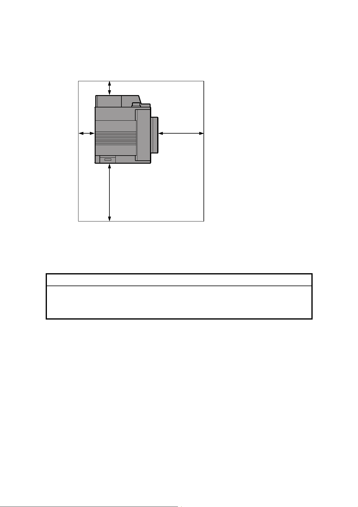
1.1.3 SPACE REQUIREMENTS
B
: Over 100 mm (4")
B: Over 100 mm (4")
A
C
C: Over 550 mm (22")
D: Over 750 mm (30")
D
G070I001.WMF
1.1.4 POWER REQUIREMENTS
!CAUTION
1. Insert the plug firmly in the outlet.
2. Avoid using an outlet extension plug or cord.
3. Ground the machine.
1. Input voltage level:
120 V, 60 Hz, More than 11 A
220 to 240 V, 50/60 Hz, More than 7 A
2. Permissible voltage fluctuation: ±10%
3. Do not put or place anything on the power cord.
1-2
Page 3
21 August 2002 MACHINE INSTALLATION
1.2 MACHINE INSTALLATION
Refer to the Operating Instructions for details.
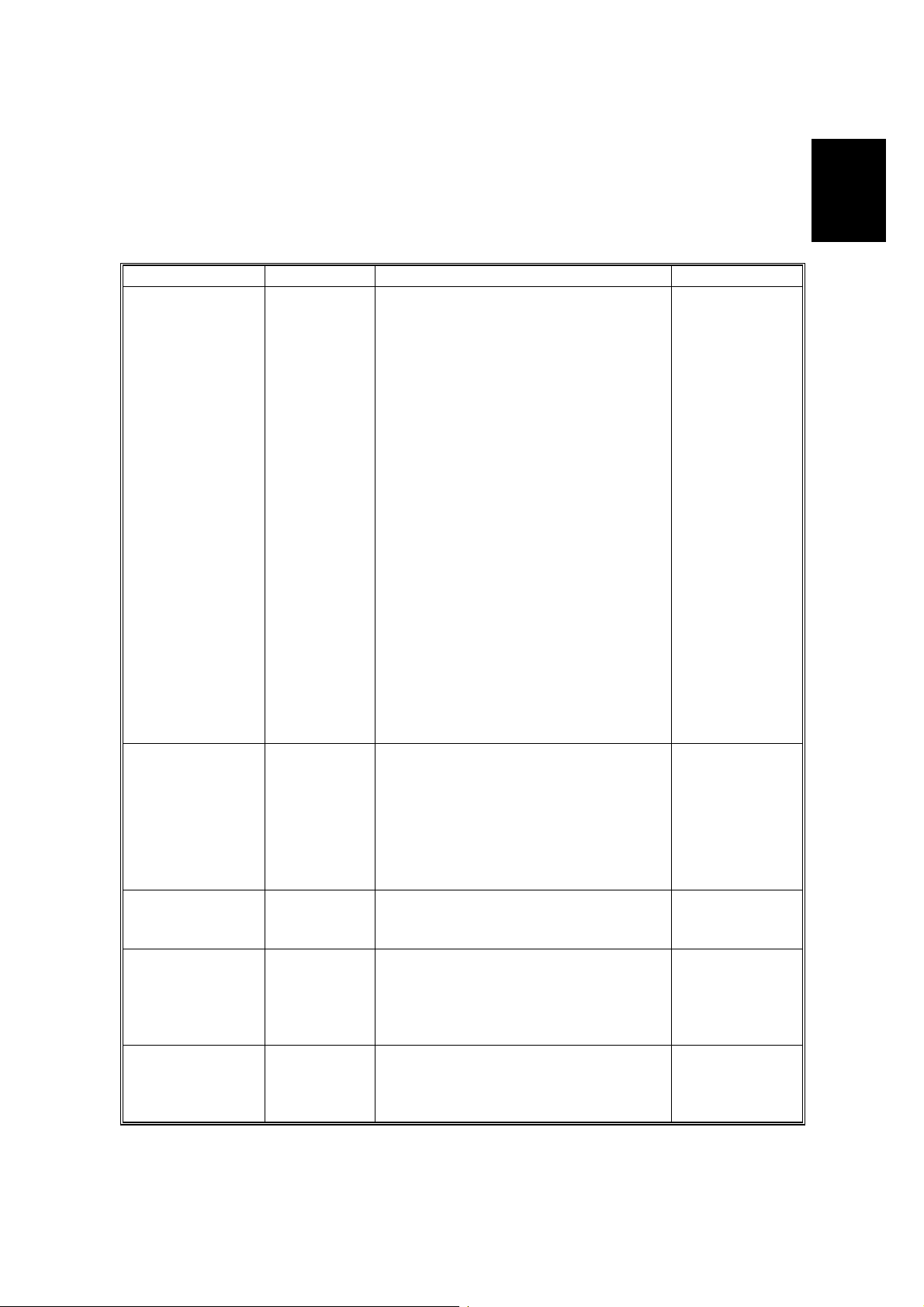
If the customer has a service contract, change the settings of the following SP
modes depending on the contract type.
Item SP No. Function Default
Meter charge SP5-930-1
(Meter_
Charge)
Counting method SP 5-04 5-1
(Counter
Method)
A3/11" x 17"
double counting
SP5-104-1
(Double
Count)
PM warning
display 1
SP5-931-1
(PM_Display
– Charger)
PM warning
display 2
SP5-931-2
(PM_Display
– PCU)
Specifies whether the meter charge
mode is enabled or disabled.
If the user is doing the user PM
procedures, set meter charge to ‘O f f’.
If the technician is doing a ll t he PM,
set meter charge to ‘On’.
Meter charge mode enabled:
• The Counter menu appears
immediately after the Menu key is
pressed.
• The counter type selected by the
counting method (SP5-045-1,
Counter Method) can be displayed
with the Counter menu.
• The counter values can also be
printed with the Counter me nu.
• The selected counter starts fro m a
negative number.
Meter charge mode disabled:
• The Counter menu is not
displayed.
• The total counter starts from 0.
Specifies whether the counting
method used in meter charge mode is
based on developments or print s.
Important:
This SP can only be done bef ore the
negative counters are res et w ith SP7825-001 (Counter Reset)
Specifies whether the counter is
doubled for A3/11" x 17" paper.
Specifies whether the PM warning for
the charge corona unit is displayed
when the replacement time arrives.
1: Displayed
0: Not displayed
Specifies whether the PM warning for
the PCU is displayed.
1: Displayed
0: Not displayed
Off
Developments
No: Single
counting
1
1
Installation
1-3
Page 4
OPTIONS 21 August 2002
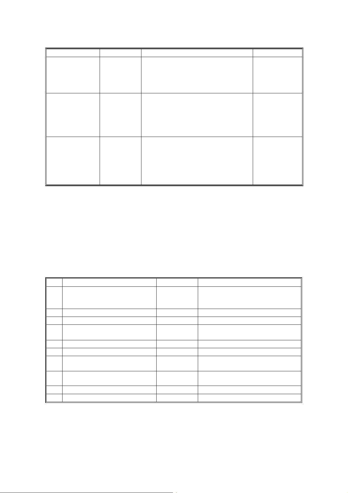
Item SP No. Function Default
PM warning
display 3
Fax No. setting SP5-812-2
Counter reset SP7-825-1
SP5-931-3
(PM_Display
- Bank_
Feed)
(FAX TEL
No.)
(Counter
Reset)
Specifies whether the PM warning for
the feed rollers in the optional paper
feed unit is displayed.
1: Displayed
0: Not displayed
Programs the service station fa x
number.
The number is printed on the cou nt er
list when the meter charge mode is
selected, so that the user can fax the
counter data to the service station.
Resets the counters to 0.
Important: Th is must be done at
installation after all the above settings
have been finished. The n egat ive
counters used in meter charge mode
will be reset to zero.
0
NOTE: 1) The default setting for this machine is meter-charge mode off.
2) The meter-charge counter cannot be reset.
1.3 OPTIONS
Refer to the Option Setup Guide for details.
No. Optional Unit Alternative Requirements
500-sheet finisher
1
2 4-bin mailbox No. 1
3 Interchange unit
Duplex unit
4
5 Paper tray unit
6 Printer hard disk
DIMM memory (64, 128, or 256
7
MB modules available)
IEEE1394 interface unit
8
9 User account enhancement unit
10 IEEE802.11b (Wireless LAN)
No. 2
• No. 3
• Hard disk or memory (extra 64
MB or more) for sort mode
• No. 3
• No. 3
• Extra 64 MB (or more) optional
SDRAM module
NOTE: 1) You cannot install the finisher and mailbox on the same machine.
2) You can install either 1 or 2 paper tray units.
1-4
Page 5

21 August 2002 REMARKS FOR INSTALLATION
1.4 REMARKS FOR INSTALLATION
In case you install this printer or you instruct customers to install, please note the
following remark for development unit installation and replacement:
After installation or replacement of the development unit, print out the development
unit check sheet by user mode (User Mode – Maintenance – Development Unit
Check).
NOTE: For details please refer to the Quick Installation Guide.
Installation
1-5
 Loading...