

Page 1
Chapter
1
General Information
This service manual contains information useful for troubleshooting, repairing,
adjusting, and maintaining a Tektronix Phaser
Printers. This manual includes troubleshooting guides, adjustment procedures,
a field replaceable units (FRU) list and assembly/disassembly procedures for
selected FRUs. To ensure complete understanding of the product, we
recommend participation in Phaser 540 service training.
®
540 and Phaser
®
540 Plus Color
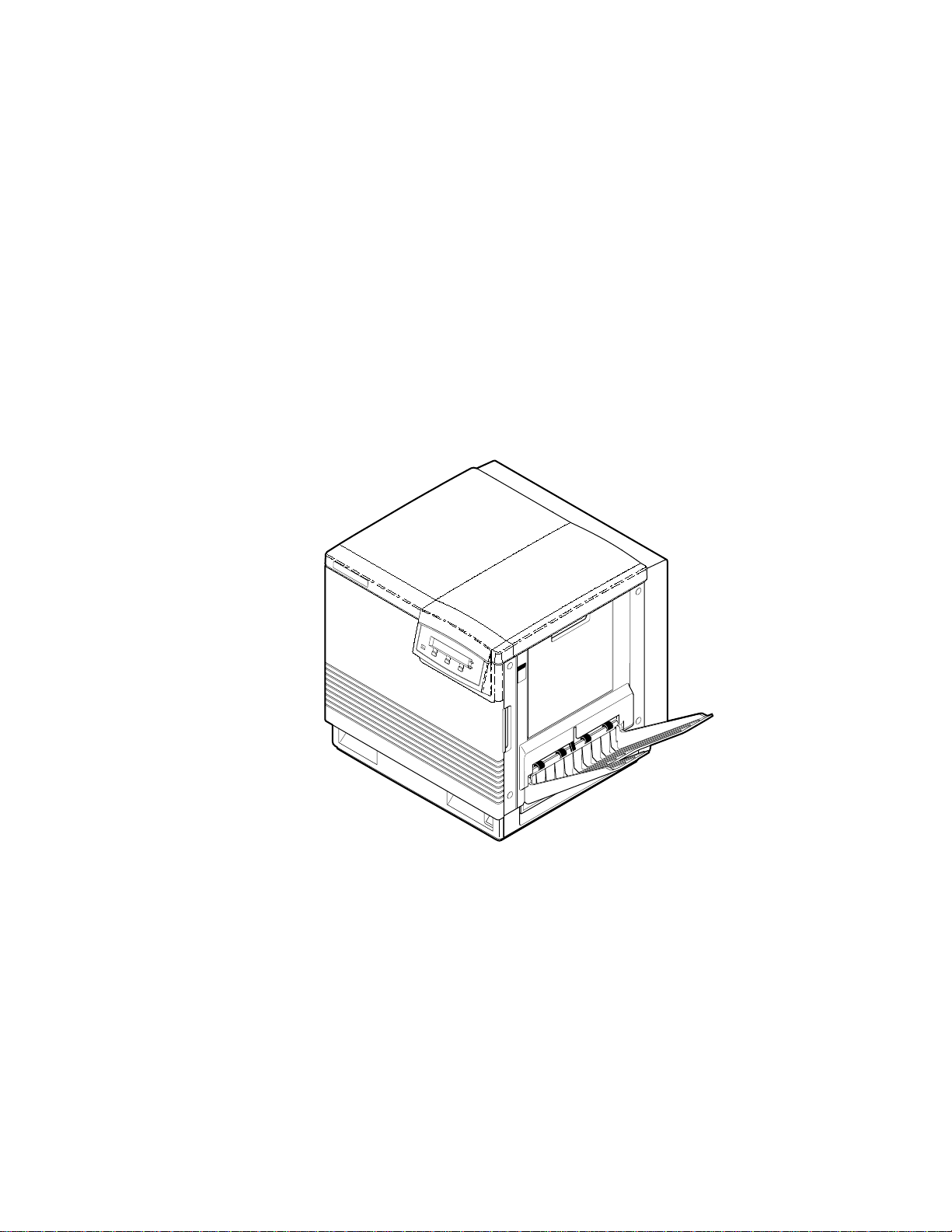
Figure 1-1 The Phaser 540 Color Printer
9013-01
Service Manual
1-1
Page 2

General Information
1
The Phaser 540 Color Printers
The Phaser 540 and Phaser 540 Plus Color Printers both combines a color laser,
continuous-tone print engine with an image processor supporting Adobe’s
PostScript Level 2 page description language (version 2015). The image
processor features a bi-directional parallel interface for host communication.
Optional network adapter cards to the image processor allow the printer to
communicate on networks using LocalTalk, serial, Ethernet or Token Ring
protocols. The Ethernet network card supports EtherTalk, Novell and TCP/IP.
With the Token Ring network card, the Phaser 540 Plus supports Toten Ring
protocols. The network cards are sometimes referred to as “smart cards”
because each houses its own processor for executing specific on-board protocols;
only data is transferred from the installed smart card to the printer’s image
processor board.
The printers each comes standard with 20 Mbytes of RAM which can be
supplemented with one or two additional 16-Mbyte RAM SIMMs. The printer
contains 39 standard, built-in fonts. The printer features a SCSI-compatible
interface to connect to an external hard disk drive for additional font storage.
An orderable option, the Phaser CopyStation can also be connected to the
printer’s SCSI port to give the printer the ability to optically copy color images.
The printer supports printing on A- and A4-sized paper and transparency film
from an A or A4-size tray. An optional two-tray second feeder (called the Lower
Tray Assembly) is available. The printer also supports manual feeding. The
Phaser 540 Plus also supports Legal-size paper in its Legal-size tray.
The printer prints at a user-selectable resolution of 300 dots-per-inch or
600 dots-per-inch. Color printing is at either 4 or 16 levels of color depending on
the amount of memory installed in the printer. After being idle for one hour the
printer switches into its Energy Star mode where it consumes less than 45 watts
of power. It “awakens” upon receiving data at any of its ports. The printer also
features a closed-loop image density sensor system that allows it to
auto-calibrate its color imaging so printing output remains consistent over the
life of the print engine and its consumable supplies.
RAM and printer capabilities
With additional RAM memory the printer’s capabilities increase:
■
With standard 20 Mbytes of RAM, the printer has a frame buffer of 16
Mbytes, an I/O buffer of 100 kbytes, an image pipeline color cache of
500 kbytes, and PostScript virtual memory of 3.6 Mbytes. With
standard 20 Mbytes of RAM, the printer can print 300 dpi
continuous-tone and 600 dpi bi-level images.
1-2
Phaser 540 Color Printer
Page 3
With 36 Mbytes of RAM, the printer has a frame buffer of 32 Mbytes,
■
an I/O buffer of 100 kbytes, an image pipeline color cache of 500
kbytes, and PostScript virtual memory of 3.6 Mbytes. With 36 Mbytes
of RAM the printer can print 300 or 600 dpi continuous-tone images
and has faster data throughput. With the additional RAM in the
Phaser 540 Plus, the scan-to-print start time of the Phaser CopyStation
is reduced to about 65 seconds.
■
With a maximum 52 Mbytes of RAM, the printer has a frame buffer of
32 Mbytes, an I/O buffer of 1 Mbytes, and image pipeline color cache
of 2 Mbytes, and PostScript virtual memory of 16.8 Mbytes.
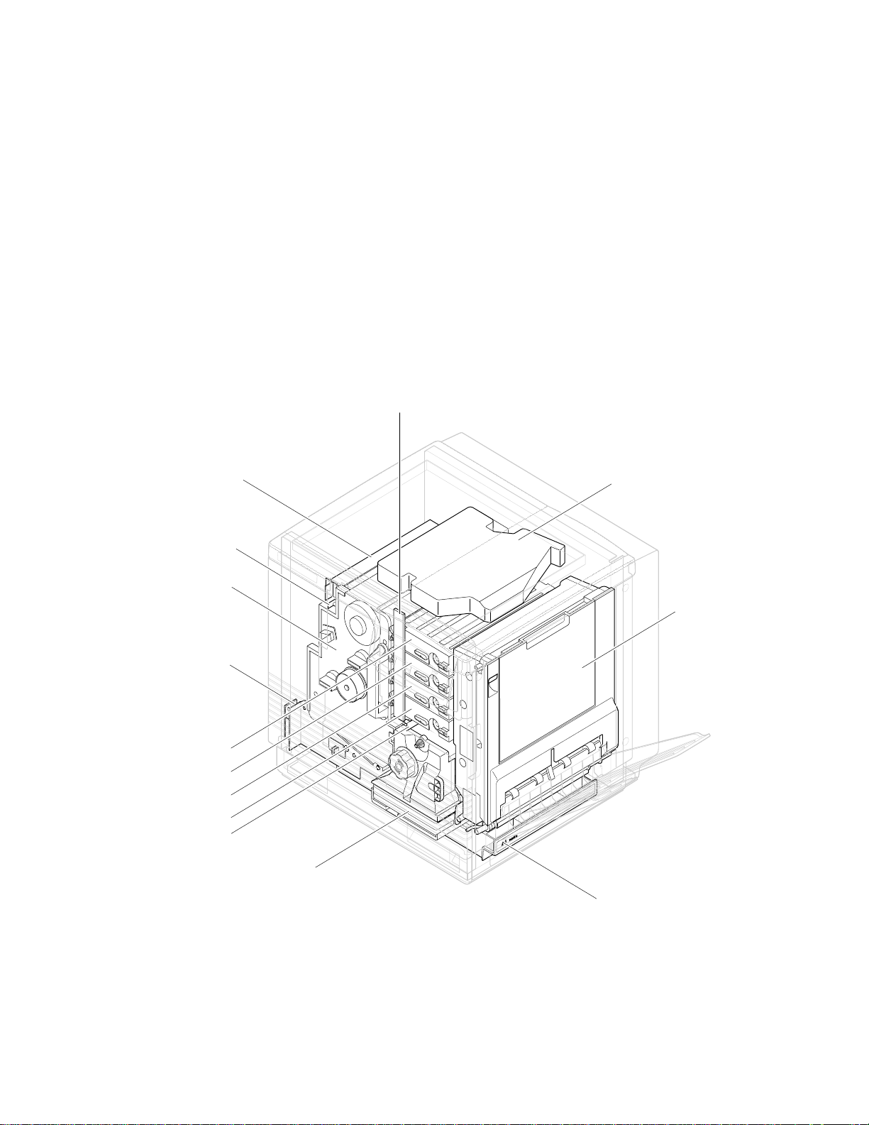
Print engine assemblies
Toner level
sensor board
General Information
1
Pre-exposure lamp
Imaging unit
Paper feeder
Black toner cartridge
Yelllow toner cartridge
Magentatoner cartridge
Cyan toner cartridge
Pre-transfer lamp
Ozone filter
Fuser
Laser scanner
Toner cartridge
selector/paper
exit unit
ER
P
A
P
A4
Paper tray
9013-02
Figure 1-2 Print engine major components
Service Manual
1-3
Page 4
General Information
1
Toner cartridge
drive unit
Power
supply fan
Power
supply unit
Engine
control board
Fuser fan
Charger
sensor board
Cleaning board
Toner
cartridge
motor
Ozone fan
Laser driver board
Image processor
board
High voltage board
Main motor
Paper feed motor
Engine driver board
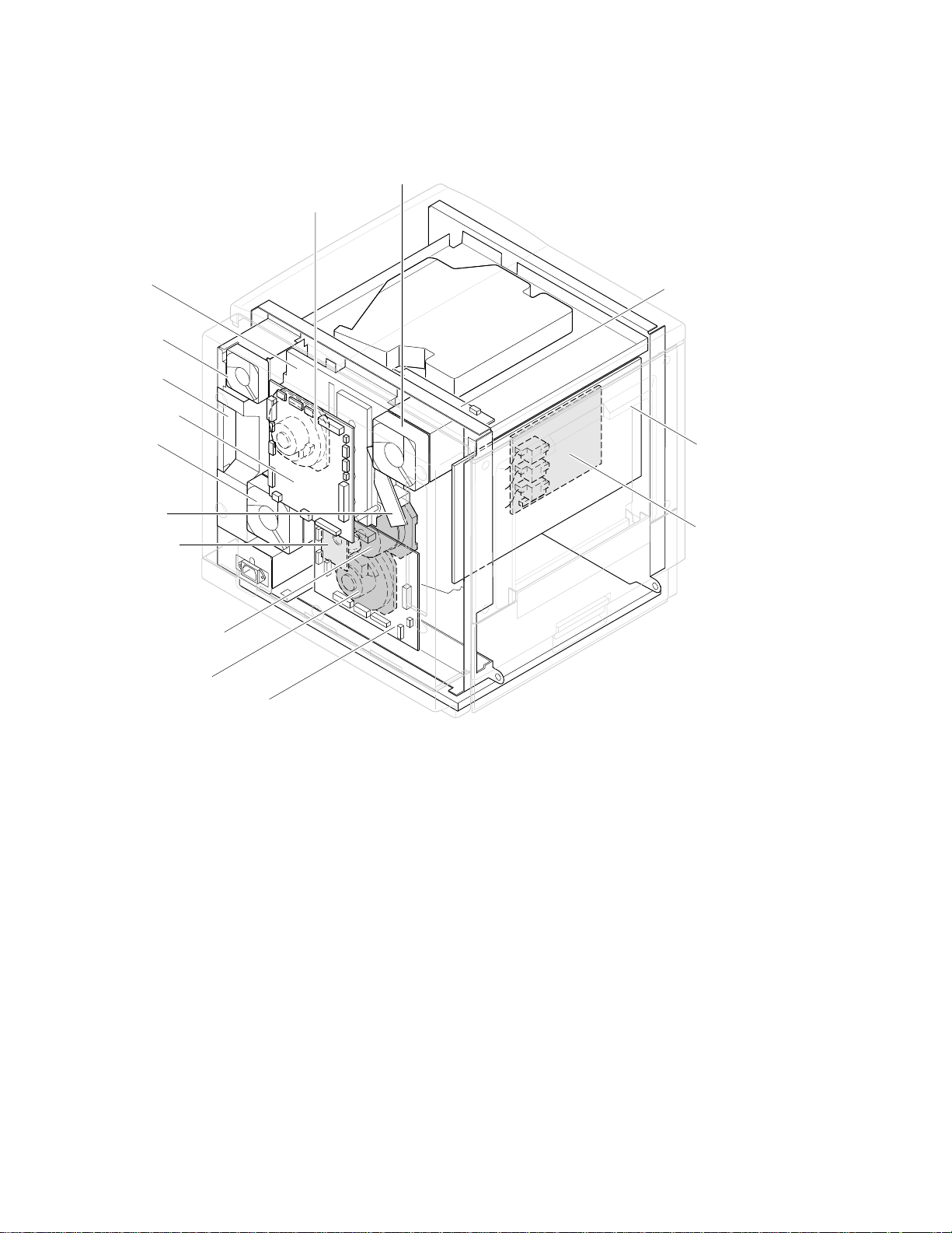
Figure 1-3 Print engine components (continued)
9013-03
1-4
Phaser 540 Color Printer
Page 5
Manual feed
sensor
Registration
sensor
Transparency
sensor
(transmitter)
Transparency
sensor
(receiver)
Toner level
sensors
(transmitters)
Accumulator belt
home position sensor
Image density
sensor
Scorotron
charger
sensor
Pre-transfer
charger
sensor
General Information
Toner level sensors
(receivers) are mounted
inside the toner cartridge
driver unit
Front right door
opened switch
Transfer waste
bin sensor
Transfer roller
position sensor
Fuser-installed
switch
Left door opened
switch
1
Paper low
sensor*
Paper tray
type sensors
Paper jam
sensor
*Unused by image processor
Power switch
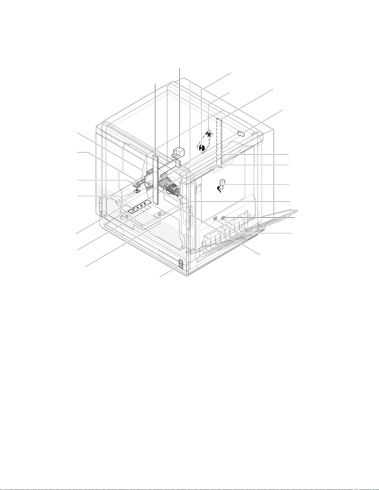
Figure 1-4 Print engine sensor, switch and solenoid locations
These sensors are not illustrated:
■
The photoconductive belt position sensor. This optical sensor marks
the home position of the photoconductive belt. It is mounted inside
the customer-replaceable imaging unit.
The photoconductive belt toner disposal bin full sensor. It is mounted
■
inside the customer-replaceable imaging unit. This ultrasonic sensor
determines if one of the imaging unit’s two waste toner bins is full
which, if true, would impair print quality. Under ordinary
circumstances, neither waste toner bin should fill up before the
imaging unit’s life is expired.
Paper-exit
sensor
Fuser-exit
sensor
Paper-empty
sensor
9013-04
The logic state of paper low sensor is not monitored or used by the image
processor.
Service Manual
1-5
Page 6

General Information
1
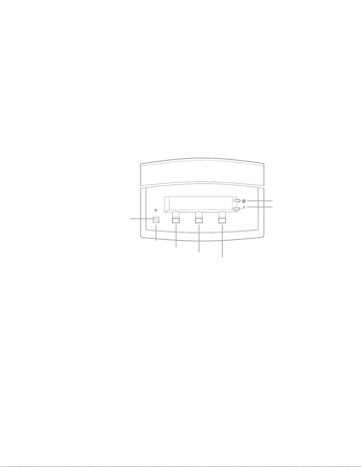
Front panel
These front panel features are found on the printer:
■
A two-line, 24-character LCD and two LEDs
Four push buttons
■
LCD
The LCD serves two purposes: displaying current controller and print
engine status information and displaying an interactive menu. Status
information includes controller status such as
Printing . Print engine status includes messages such as Out of paper ,
Paper Jam , and Out of toner . The interactive menu can only be entered
while the print engine and controller are idle. The interactive menu allows the
user to review and change certain NVRAM, I/O ports and peripheral
parameters. Using the front panel to review and change parameters is discussed
in Chapter 9, “Checks and Adjustments.”
Ready , Receiving data and
Buttons
cancel an operation while in the interactive menu. The functions of Buttons 2, 3
and 4 are defined by the particular menu or function being displayed on the
LCD display. The bottom row of the LCD labels the current function of each
button.
In addition, pressing the buttons as you turn on the printer enables certain
diagnostic modes:
■
■
■
The Chapter 9 topic, “Resetting NVRAM” on page 9-9 explains how to use the
front panel buttons to reset the NVRAM to its factory default values.
Button 1, the left-most button, is labeled the Exit key and is used to
Pressing and holding Button 1, as you turn on the printer, skips
power-up diagnostics (except for a brief kernel test) and proceeds to
PostScript startup.
Pressing and holding Button 2, as you turn on the printer, executes
extended diagnostics.
Pressing and holding Button 3, as you turn on the printer, executes
interactive service tests. These are described in “Printer
self-diagnostics” on page 9-6.
1-6
Phaser 540 Color Printer
Page 7
On
General Information
LEDs
The Power LED indicates the printer has +5 VDC available for its logic
control boards.
The
Error LED has three indications:
■
Off indicates that no errors have been detected.
■
indicates a warning to the user. An explanatory message, such as
Low Paper , is displayed on the LCD.
Blinking indicates an error has been detected. An error message, such
■
Paper Jam at Output , is displayed on the LCD. Error codes
as,
are listed and explained in the Section 6 topic, “Error messages” on
page 6-19.
1
Exit
Exit
Button 1
Button 2
Button 3
Button 4
Figure 1-5 The front panel and its functions
Power
Error
9013-06
Service Manual
1-7
Page 8

General Information
1
Rear panel
Connectors
The rear panel of the Phaser 540 printer features the host interface connectors to
the printer. It includes the following connectors:
Standard parallel (high-density connector).
■
■
SCSI high-density connector (font hard disk drive or
Phaser CopyStation only).
With the addition of a network card, the printer can feature either of these
groups of connectors:.
■
ThinNet (10base2) and Twisted Pair (10baseT) Ethernet connectors.
This is Option P1 and P2.
■
RS-232 serial and LocalTalk connectors. This is Option P2
Unshielded Twisted Pair (10baseT) and shielded Twisted Pair (DB-9)
■
Token Ring connectors. This is Option P4.
The figure below illustrates the rear panel.
Parallel
Smart card slot
for network card
Phaser™ Share
Ethernet Card
10Base2
Link
RX
TX
10Base-T
LocalTalk/Serial Card
Phaser™ Share
Serial LocalTalk®
RS-232
serial
LocalTalk
1-8
Figure 1-6 The Phaser 540 rear panel
Phaser 540 Color Printer
SCSI
Option
P1
P2
Option
P3
9013-05
Page 9

on
on
Network card LEDs
The Ethernet network card has two LED indicators:
■
■
Note
General Information
TX indicator (yellow); blinks while data is transmitted to the host. The
LED is off while no data is being sent.
Twisted Pair (10baseT). RX indicator (green); blinks while the
network card is receiving data. The LED is
being received. If the LED is
hardware) has occurred at the network hub.
ThinNet (10base2). RX indicator (green); blinks while the network
card is receiving data. The LED is
received. If the LED is
has occurred at the network hub.
Do not use both Ethernet connectors at the same time. If both are used
the 10base2 line is ignored.
on steady , then a problem (probably hardware)
off steady , then a problem (probably
off stead y while no data is being
on steady while no data is
1
Test print button
The Token Ring network card has two LED indicators:
■
Connection (yellow); off when the printer is not inserted into the Token
blinks while the printer is attemping to insert itself into the Token
Ring,
Ring,
Ring Speed (green); off when the card is set for 4 megabits per second
■
(MBPS),
When both LEDs blink, a network card failure has occured.
■
In the center of the rear cabinet panel is the test print button. Pressing this
button while the printer is idle causes the print engine to print a built-in test
print. The print is made independently of the image processor board.
when the printer is properly inserted in the ring.
when the card is set for 16 MBPS.
Service Manual
1-9
Page 10

General Information
On
1
Health LED
A health LED indicates the status of the image processor board. The health LED
is mounted on the image processor board and is viewable through the grill
behind the manual feed tray. (The grill is the removable RAM SIMM options
cover.) Once the PostScript code is loaded into memory and the image processor
is initialized and running, the image processor blinks the LED at a one-second
rate.
Blinking (at a steady rate): The printer is operating normally. The LED
■
blinks irregularly during power-up self-diagnostics.
If a soft error occurs, the image processor board operates, but in a
reduced capacity. Soft failures include failure of expansion memory
SIMMs or any of the interface ports. When a soft error occurs, the
printer automatically prints a startup page listing the error.
■
or Off : A hard error condition has occurred that would keep the
image processor board from operating.
Media tray type sensing
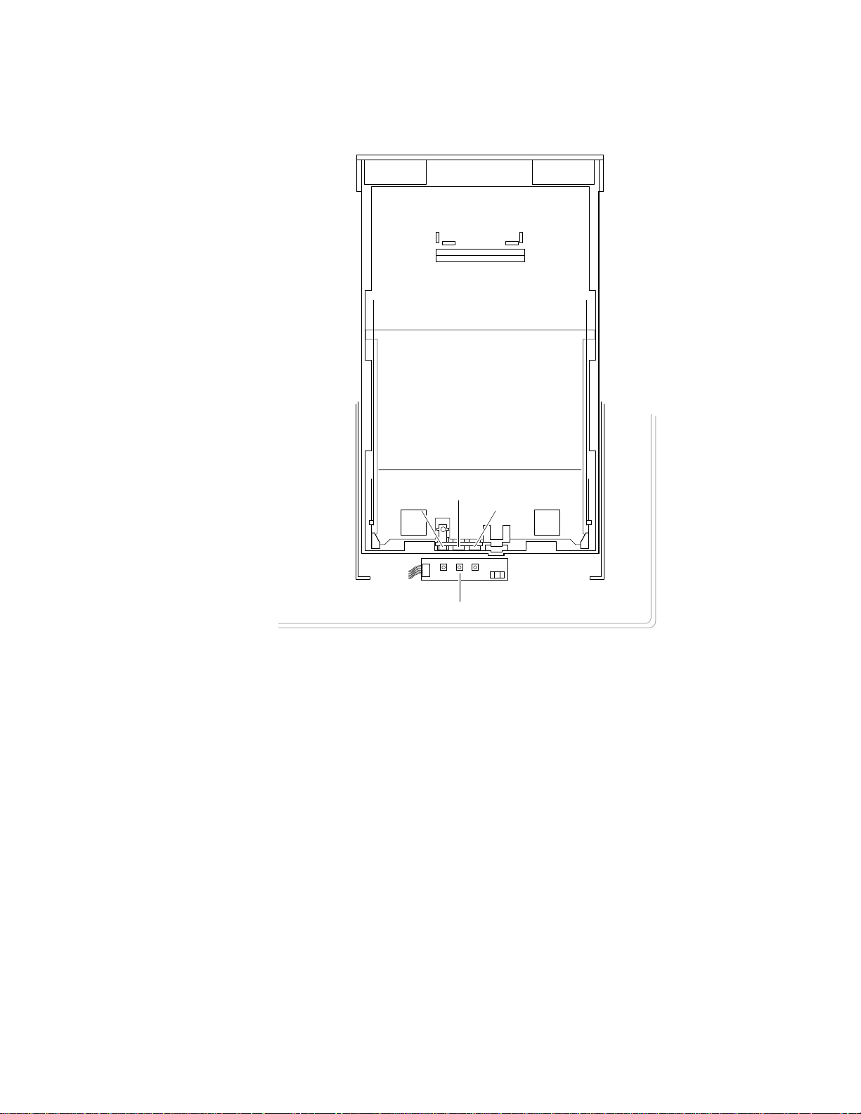
The combinations of the three tray sensors “tell” the print engine what type of
paper tray is installed. The tray sensors are located on the left-side interior of
the paper tray slot. Sensor actuators are attached to the bottom end of the tray to
close the appropriate sensor. There are four tray types:
■
Letter (A-size) paper
Letter (A-size) transparency film
■
■
Metric Letter (A4-size) paper
■ Metric Letter (A4-size) transparency film
■ Legal-size paper (Phaser 540 Plus)
Table 1-1 Tray switch sensor combinations
Left switch Middle switch Right switch Tray type
Closed Open Open Letter (A-size) paper
1-10
Closed Closed Open Letter (A-size) transparency film
Open Open Closed Metric Letter (A4-size) paper
Closed Open Closed Metric Letter (A4-size) transparency film
Open Closed Open Legal-size paper
Phaser 540 Color Printer
Page 11
General Information
1
Sensor actuators
Middle
Left
Right
Tray sensors
Figure 1-7 Tray switch sensors and actuators
9013-40
Service Manual
1-11
Page 12

1
General Information
Specifications
Table 1-2 Physical dimensions
Dimensions Specification
Height:
Width: 48.3 cm (19 in.) With output tray: 69.6 cm (27.4 in.)
Depth: 48.3 cm (19.5 in.)
45.7 cm (18 in.) With Lower Tray Assembly: 68.6 cm (27 in.)
Weight: Approximately 53.3 kgs (117 lbs.) with Lower Tray Assembly
and consumables installed.
Approximately 39.1 kgs (86.2 lbs.) without Lower Tray
Assembly.
Table 1-3 Printer clearances
Clearances Specification
Top: 7.6 cm (3 in.)
Left: 7.6 cm (3 in.)
Right: 10.2 cm (4 in.) for handling the output tray
Front: Unlimited for removal of consumable
Rear: 15.3 cm (6 in.) for connecting computer cable and pow er cord
Bottom: No obstruction under printer that could block its cooling vents.
Mounting surface
flatness:
Within 2 degrees of horizontal with all four feet in contact with
the table surface.
1-12
Phaser 540 Color Printer
Page 13

General Information
Table 1-4 Functional specifications
Characteristic Specification
Printing process Electro-photographic, four color (CMYK) transfer printing
1
Color medium Four toner cartridges each contain one of four colors: cyan,
Addressability Standard mode: 300 x 300 dots-per-inch text and graphics
Printing speed Time from paper-load to paper-eject:
Minimum printing
margins
Usable paper A-size (letter) and A4-size (Metric letter) and Legal-size of a
Paper tray capacity 250 sheets using 20-lb. paper. 100 sheets of transparency
magenta, yellow or black. The toner is a nonmagnetic,
monocomponent contact medium.
Enhanced mode: 600 x 600 dpi text and graphics
Four-color 3.5 pages per minute at 300 dpi
paper: 1.75 pages per minute at 600 dpi
Monochrome: 14 pages per minute at 300 dpi
7 pages per minute at 600 dpi
Four-color transparency: 1.3 pages per minute at 300 dpi
Print times do not include image processing time, which can
vary depending on image complexity.
All sides, 5 mm (0.2 ins.).
good quality, or premium laser printer or copier paper.
film. The optional Lower Tray Assembly also uses trays with
the same capacity.
Table 1-5 Electrical specifications
Characteristic Specification
Primary line voltages 87 to 128 VAC (115 VAC or 100 VAC nominal); 174 to 260
Primary voltage
frequency range
Power consumption 60 watts (fuser off), 850 watts (fuser on) during Ready state,
Primary voltage fusing 110 VAC configuration – 10 amp
Secondary DC voltages Image processor:
RF emissions Both 110 and 220 VAC-configured instruments pass these
VAC (220 VAC nominal)
47 to 63 Hz
950 watts during Warm-up state, 45 watts during Energy Star
state
220 VAC configuration – 6.3 amp
+ 5 VDC ± 0.25 (1A minimum, 6 A maximum)
± 12 VDC ± 0.6 (100 mA max)
Print engine:
+ 5V ± .25 (2.2 A max)
+ 12V ± .25 (0.4 A max)
- 12V ± .25 (0.1 A max)
+ 24V ± .25 (3.0 A max)
standards: FCC Part 15 Class B
VDE Class B
EN55022 (CISPR 22) Class B
VCCI (CISPR 22) Class B
Service Manual
1-13
Page 14

1
General Information
Table 1-6 Environmental specifications
Characteristic Specification
Temperature
Operating
Non-operating
Storage
Humidity
Operating
Non-operating
10o to 32.5o C (50oto 91oF)
o
0
to 40o C (32o to 104o F)
o
-20
to 60o C (-4
o
to 140o F)
Media should be acclimated 24 hours before using in the
printer.
10 to 80% relative humidity, non-condensing
10 to 90% relative humidity, non-condensing
Media should be acclimated 24 hours before using in the
printer.
Altitude
Operating
Non-operating
Vibration/shock
Operating
Non-Operating
(vibration)
Non-operating (shock)
Acoustic Noise
(operating)
o
0 to 2500 m (8,000 ft.) at 25
C
0 to 15000 m (50,000 ft.)
(Fuser maximum 4000 m (13,300 ft.)
May drop any side or corner 50 mm (2 in.) without impairment
of subsequent operation.
On five mutually perpendicular axes: 0.5 g, 25-minute sweep,
5 to 200 to 5 Hz, 100 to 200 sec./sweep cycle. No resonant
frequencies below 50 Hz.
30 g, trapezoidal flared pulse, 20 msec each axis.
Aver age sound le vel (LEQ) is less than 53 dbA. Peak noise in
standby mode is 47 dbA.
1-14
Phaser 540 Color Printer
Page 15

Regulatory specifications
The printer is a recognized component in conformance with the following
regulatory standards:
■ The packaged product meets ASTM D4169-86 and ASTM D4728-87
Transportation Standards.
■ Listed UL 1950 Information Processing and Business Equipment.
■ Certified CSA C22.2 No. 950 Safety of Information Technology
Equipment, Including electrical Business Equipment.
■ GS licensed IEC 950 (1991) Second Edition; EN60950 Information
Processing and Business Equipment.
■ VDE 0871/6.78 (Class B) Regulation for the Radio Frequency Interface
Suppression of High Frequency Apparatus and Installations.
■ VDE 0875, Regulation for RFI Suppression of Electrical Equipment
and Installations
General Information
1
■ EN55022 (CISPR 22) Class B
VCCI (CISPR 22) Class B
■ FCC Class B (for 115 VAC equipment) pursuant to Sub-part J
of Part 15.
Service Manual
1-15
Page 16

Page 17

Service Manual
Phaser
®
540 and Phaser
Color Printers
®
540 Plus
Warning
The following servicing instructions are for
use by qualified service personnel only. To
avoid personal injury, do not perform any
servicing other than that contained in
operating instructions unless you are qualified
to do so.
This printing June 1995
070-9013-01
Page 18

Copyright
©
1995 by Tektronix, Inc., Wilsonville, Oregon. Printed in the United States of America. All rights
reserved. Contents of this publication may not be reproduced in any form without permission of Tektronix, Inc.
This instrument, in whole or in part, may be protected by one or more U.S. or foreign patents or patent applications.
Information provided upon request from Tektronix, Inc., P.O. Box 1000, Wilsonville, Oregon 97070-1000.
If acquired subject to FAR or DFARS, the following shall apply:
Unpublished — rights reserved under the copyright laws of the United States.
■
■
Restricted Rights Legend — Use, duplication or disclosures by the government is subject to restrictions as set forth
in subparagraph (c) (1)(ii) of the Rights in Technical Data and Computer Software at DFARS 252.227-7013, or in
subparagraph (c) (2) of the Commercial Computer Software – Restricted Rights clause at FAR 52.227-19, as
applicable. Tektronix, Inc., P.O. Box 1000, Wilsonville, Oregon 97070-1000.
Tektronix
®
is a registered trademark of Tektronix, Inc. TekColor™ and Photofine™ are trademarks of Tektronix, Inc.
Phaser™ is a trademark of Tektronix, Inc. for color printers and related products.
Adobe™ and PostScript™ are trademarks of Adobe Systems, Incorporated which may be registered in certain
jurisdictions.
EtherTalkg
®
is a registered trademark of Apple Computer, Incorporated.
Times™, Helvetica™, and Palatino™ are trademarks of Linotype-Hell AG and/or its subsidiaries.
Micronta
Microsoft
®
is a registered trademark of Radio Shack.
®
and Microsoft Windows® are registered trademarks of Microsoft Corporation.
®
Novell
OS/2
PANTONE
and NetWare
®
is a registered trademark of International Business Machine Corporation.
®
* Colors generated by the Phaser 540 and 540 Plus Color Printers are four-color process simulations and
®
are registered trademarks of Novell, Inc.
may not match PANTONE-identified solid color standards. Use current PANTONE Color Reference Manuals for
accurate colors.
PANTONE Color simulations are only obtainable on these products when driven by qualified Pantone-licensed
software packages. Contact Pantone, Inc. for a current list of qualified licensees.
* Pantone, Inc.’s check-standard trademark for color reproduction and color reproduction materials.
© Pantone. Inc., 1988.
TCP/IP is a trademark of FTP Software. Copyright (c) 1986, 1987, 1988, 1989 by FTP Software, Inc. All rights
reserved. PC/TCP for DOS is based on a set of programs originally designed and developed by the Massachusetts
Institute of Technology. FTP Software has made extensive modifications and enhancements to the M.I.T. programs.
TokenTalk® is a registered trademark of Apple Computer, Incorporated.
TORX™ is a trademark of TEKTRON.
The X Window System™ is a trademark of Massachusetts Institute of Technology.
Other marks are trademarks or registered trademarks of the companies with which they are associated.
TE/JG
Page 19

Users safety summary
Terms in manual:
Power source:
conductor and ground. Use only the specified power cord and connector. Refer to a qualified service technician for
changes to the cord or connector.
Operation of product:
product. Do not operate without the covers and panels properly installed. Do not operate in an atmosphere of
explosive gases.
Safety instructions:
Terms on product:
cover the hazardous area. Also applies to a hazard to property including the product itself.
DANGER A personal injury hazard exists in the area where you see the sign.
Care of product:
power cord or plug is frayed or otherwise damaged, if you spill anything into the case, if product is exposed to any
excess moisture, if product is dropped or damaged, if you suspect that the product needs servicing or repair, and
whenever you clean the product.
Ground the product:
necessary, contact a licensed electrician to install a properly grounded outlet.
Symbols as marked on product:
CAUTION Conditions that can result in damage to the product.
WARNING Conditions that can result in personal injury or loss of life.
Does not apply more than 250 volts RMS between the supply conductors or between either supply
Avoid electric shock by contacting a qualified service technician to replace fuses inside the
Read all installation instructions carefully before you plug the product into a power source.
CAUTION A personal injury hazard exists that may not be apparent. For example, a panel may
Disconnect the power plug by pulling the plug, not the cord. Disconnect the power plug if the
Plug the three-wire power cord (with grounding prong) into grounded AC outlets only. If
DANGER high voltage:
Protective ground (earth) terminal:
Use caution. Refer to the manual(s) for information:
!
Laser use caution. Refer to the manual(s) for information:
WARNING:
cause an electrical shock. Electrical product may be hazardous if misused.
If the product loses the ground connection, usage of knobs and controls (and other conductive parts) can
Page 20
Service safety summary
For qualified service personnel only:
Do not service alone:
Do not perform internal service or adjustment of this product unless another person capable of
Refer also to the preceding Users Safety Summary.
rendering first aid or resuscitation is present.
Use care when servicing with power on:
Dangerous voltages may exist at several points in this product. To avoid
personal injury, do not touch exposed connections and components while power is on.
Disconnect power before removing the power supply shield, soldering, or replacing components.
Do not wear jewelry:
Remove jewelry prior to servicing. Rings, necklaces, and other metallic objects could come into
contact with dangerous voltages and currents.
Power source:
This product is intended to operate from a power source that will not apply more than 250 volts rms
between the supply conductors or between either supply conductor and ground. A protective ground connection by
way of the grounding conductor in the power cord is essential for safe operation.
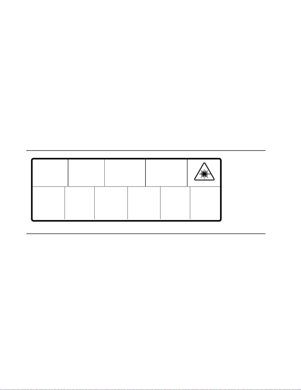
This product is certified under IEC 825 as a Class 1 Laser Product.
DANGER:
Invisible laser radiation
when open and interlock
defeated.
AVOID DIRECT
EXPOSURE TO BEAM.
PELIGRO:
Cuando se abre y se
invalida el bloqueo, se
producen radiaciones
invisibles de láser.
EVITESE LA
´
EXPOSICION
DIRECTA A TALES
RAYOS.
CAUTION:
Invisible laser radiation
when open and
interlocks defeated.
AVOID DIRECT
EXPOSURE TO BEAM.
VARNING:
Osynlig laser-
strálning när denna
del är öppnad och
spärrar är
urkopplade.
STRÅLEN
ÄR FARLIG.
VORSICHT:
Unsichtbare Laserstrahlung,
wenn Abdeckung geöffnet
und Sicherheitsverriegelung
überbrückt.
NICH DEM STRAHL
AUSSETZEN.
VAROI:
Näkymätön
avattaessa ja
suojalukitus
ohitettaessa olet
alttiina lasersäteilylle.
ÄLÄ KATSO
SÄTEESEN.
ATTENTION:
Rayonnement laser invisible
dangereux en cas
d'ouverture et lorsque
la sécurité est neutralisée.
EXPOSITION DANGEREUSE
AU FAISCEAU.
VARNING:
Osynlig laserstrálning
när denna del är
öppnad och spärrar är
urkopplade.
BETRAKTA EJ
STRÅLEN.
ADVARSEL:
Usynlig laserstràling
ved abning når
sikkerhedsafbrydere
er ude af funktion.
UNDGÅ UD
ÆTTELSE FOR
STRÅLING.
Class 3B
ADVARSEL:
Usynlig laserstraling
nar deksel åpnes og
sikkerhedslas brytes.
UNNGÅ
EKSPONERING
FOR STRÅLEN.
PJQT4521ZA
9008-78
Page 21

Index
A
Adobe PostScript Level 2
antistatic mat
authorization code, TCP/IP
automatic color correction
8-1
1-2
5-16
8-27
B
BBS
4-10
block diagram of printer
5-2
C
cleaning the printer
clearances, printer
communication parameters
serial and parallel ports
communication setup
configuration page
description
configuring a Novell server for the printer
configuring TCP/IP
connecting the printer to a Token Ring
network
connecting the printer to an Ethernet network
connecting the printer to the Macintosh
connecting the printer to the PC
connectors
rear panel
Customer Support Hotline
2-14
1-8
2-9
2-3
7-1
2-20
2-31
,
2-10
2-8
4-10
2-9
2-8
2-30
D
driver and communication setup
2-20
E
electronic bulletin board service
Engine diagnostics (interactive)
engine failure codes
EuroHAL, automated fax system
6-19
4-10
9-7
4-8
2-9
F
field replaceable units list
Font Downloader Utility
front panel
description
front panel menu
front panel, messages
FRUs
removal and replacement
1-6
9-2
6-19
A-1
2-11
8-1
G
Graphics Supplies Order Desk
2-3
H
HAL, automated fax system
hard error
health LED
Highly Automated Library (HAL)
1-10
1-10
4-7
I
image processor
2-3
9-5
4-4
troubleshooting
image processor board
theory
imaging unit sensitivity to light
interface cables
5-18
J
Jams
6-11
K
key operator
training
4-1
L
laser electrophotography
laser printing, theory
7-2
5-9
laser scanner
Laserwriter Utility
Lubrication
2-11
5-4
5-4
,
2-4
4-7
Service Manual
Index-1
Page 22

M
Macintosh
connecting the printer
printing
using the Error Handler Utility
Measuring power supply voltages
Media problems
Microsoft Windows
standard PostScript printer driver
3-1
6-8
2-8
3-4
6-3
2-24
N
network card, installing
normal power-up self-test, image processor
Novell configuration
Novell Netware verification
null modem cable
2-29
2-30
8-26
3-7
O
OS/2 connection verification
OS/2 Version 2, Tektronix driver
OS/2 Version 2.0, loading drivers
3-6
2-25
2-25
P
paper path
6-8
jams
3-5
1-2
1-2
5-6
5-4
5-17
6-1
2-9
2-1
7-1
5-15
6-24
3-8
5-6
Paper picking,theory
PC
connecting the printer
using the Error Handler Utility
PC verification
Phaser 540
description
photoconductive belt
PostScript Level 2
power supply
verifying
power supply theory
power-up sequence
pre-exposure during laser printing
pre-installation interview
preventive maintenance
print modes, description
print quality problems
6-3
9-6
printcap file
printer
troubleshooting
printer page description file
printing from a Machintosh
printing test prints
2-29
6-1
9-4
3-4
3-1
R
RAM and printer capabilities
RAM SIMMs, installing
rear panel
connector
description
registration, checking
regulatory standards
removal procedures
required tools, disassembly
resetting NVRAM, image processor
1-8
1-8
9-10
1-15
8-1
1-2
8-24
8-1
9-9
S
safety interlock 6-5
printer
1-10
2-11
2-11
9-6
6-3
1-10
2-1
4-10
6-9
2-25
2-13
4-7
SCSI address
SCSI hard disk drive, installing on the
self-test modes
image processor
self-test print
sensing media
Service Option S0
service support, calling
skewed copy
soft error
Standard Windows PostScript driver
updating
startup page
description
supplies, ordering
Index-2
Phaser 540 Color Printer
Page 23

T
TCP/IP, configuring 2-31
TCP/IP, enabling
TCP/IP, verification of printing
TekColor
terminator, SCSI
Test Pattern Generator
test patterns
testing the print engine
theory of laser printing
Timeouts, Windows
toner cartridges during printing
Transmission Retry, Windows
tray sensors
troubleshooting
troubleshooting the printer
2-20
3
using
descriptions
image processor
8-27
2-11
B-1
6-2
5-4
2-23
2-23
1-10
9-5
6-1
U
using the Error Handler utility
for Macintosh
3-8
for PC
for workstation
3-4
3-10
3-9
5-10
V
verifying a PC can print 3-5
verifying a workstation can print
verifying and printing using the TCP/IP
protocols
3-9
3-9
W
Windows 3.1 driver verification 3-5
Windows 3.1, Tektronix driver
Windows printer driver
configuring
installing
workstation
connecting the printer
using the Error Handler Utility
workstation verification
wrinkled print
2-22
2-21
6-28
2-21
2-9, 2-10
3-10
3-9
Service Manual
Index-3
Page 24

Page 25

Appendix
D
Test Pattern Generator
The Test Pattern Generator contains PostScript scripts to start test patterns for a
number of Tektronix color printers. It allows you to test a printer as if it were
receiving a file from a host computer. The test patterns are generated by the
printer's image processor and then printed by the print engine.
Note
The Test Pattern Generator should contain firmware version 1.2 or
higher.
Service Manual
D-3
Page 26

1.
2.
3.
4.
D
Test Pattern Generator
To use the Test Pattern Generator, do the following:
Select a test pattern to be printed using the Test Pattern Generator's
five DIP switches. The following tables lists the available test
patterns.
Plug the Test Pattern Generator onto the printer's parallel port. Use
the parallel cable adapter (013-0299-00) to convert between the Test
Pattern Generator’s Centronics-style connector and the printer’s
new-style, high-density parallel port connector. You do not have to
turn the printer off; you can plug in the Test Pattern Generator “hot.”
Press the Test Pattern Generator's START button. Its green LED
flashes as you press the button.
The printer will print the transmitted print file. The front panel
displays the message “Waiting for data,” with the READY light
flashing, for five minutes after a test print has been sent to the printer.
However, you do not have to wait five minutes before sending
another test print from the Test Pattern Generator; the printer will
accept another test print.
Besides print files, the test pattern generator also allows you to turn off and on
the printer's startup page.
Additionally, the Test Pattern Generator lets you set up a printer for printing
from a 4511A Network Interface. To do so, just select the appropriate DIP switch
setting.
Table D-1 Test Pattern Generator DIP Switch settings for Phaser 540
Pattern or function 1 2 3
Print quality test pattern On On On On On
Blank sheet Off On On On On
Engine Pattern 1
(100%)
Service print 1 Off Off On On On
Blank sheet On On Off On On
Engine pattern 2 (50%) Off On Off On On
Service print 2 On Off Off On On
Enable startup page Off Off Off On On
Disable startup page On On On Off On
On Off On On On
45
D-4
Phaser 540 Color Printer
Page 27
Appendix
C
Wiring Diagram
Power
supply
fan
Door-
open
switch
Power
switch
Fuser-
installed
sensor
SCSI
Parallel
Serial
Network
card
Front panel
J24
J11
Image
J3
processor
J12
J4
CN 853
CN 851
CN 802
CN 804
J22
CN 854
Power
supply
J21
CN 855
CN 852
CN 805
Laser driver board
CN 501
CN 1
CN 5
CN 12
CN 503
CN 8CN 3
Engine
control
board
CN502
CN 11
CN 16
CN 4
CN 9
CN 7
CN 6
CN 13
CN 540
Laser
scanner
CN 1
CN 570
CN 701
High voltage
power supply
board
CN 627
Image density
sensor connector
CN 619
Toner cartridge
level sensor
(Receiver) and
roller clutch
board
CN 625
Charger unit
sensor board
CN 624
Imaging unit
CN 632
Accumulator belt
position sensor
Toner cartridge
sub bias board
FTR Orange
DEV Yellow
STR Black
CHG Red
PTC White
GRID Blue
CN 628
BK sensor
CN 620
CN 621
CN622
CN623
CN 626 CN 630
B
Y
M
C
Pre-exposure
lamp
CMY sensor
Fuser
Left door closed
sensor
Fuser fan
Paper-feed motor
Developer cartridge
drive motor
Main motor
Cleaning board
Paper tray switches
CN 618
CN 307
CN 312
CN 304
CN 306
CN 305
CN 313
CN 302
CN 311
CN 2
CN 301
Engine
driver
board
CN 310
Optional
lower tray
assembly
CN 14
CN 17
CN 303
CN 309
CN 308
Ozone fan
Toner cartridge level
(transmitter) sensor
Pre-transfer lamp
CN 601
Paper
feeder
Exit tray full
CN 617
sensor
CN 611
Exit roller
sensor board
Toner cartridge
CN 615
movement sensor
CN 616
Cam motor
board
CN 603
CN 604
CN 602
CN 606
CN 605
CN 614
CN 612
CN 613
Paper-pick sensor
Transp sensor
Registration sensor
Transfer roller solonoid
Registration clutch
Fuser exit
CN 610
sensor
Switchback solenoid
Face switching solenoid
9013-52
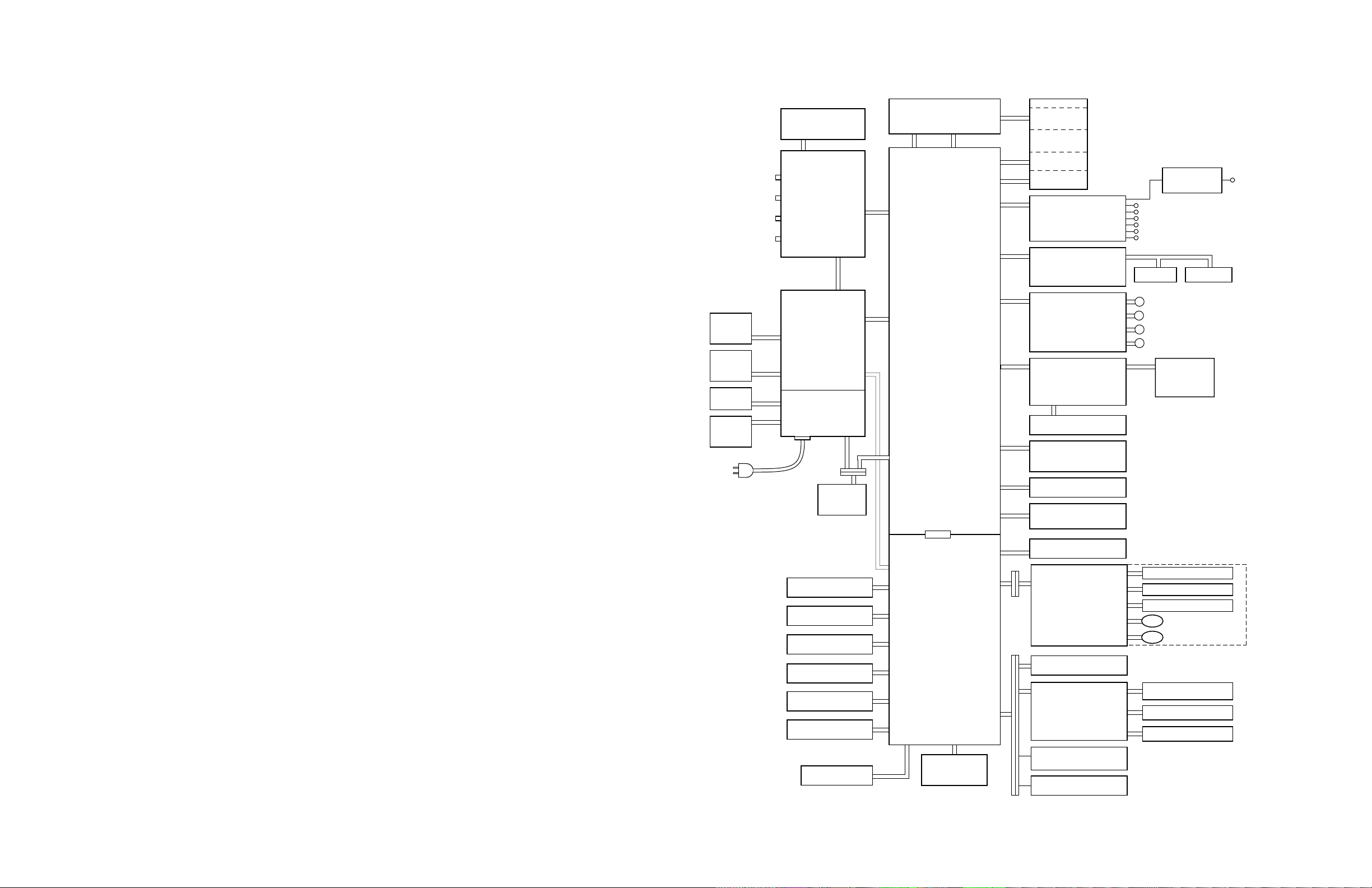
Figure C-1 Wiring diagram
Service Manual
C-1
Page 28

Page 29

Contents
1 General Information
The Phaser 540 Color Printers 1-2
RAM and printer capabilities 1-2
Print engine assemblies 1-3
Front panel 1-6
Rear panel 1-8
Network card LEDs 1-9
Test print button 1-9
Health LED 1-10
Media tray type sensing 1-10
Specifications 1-12
Regulatory specifications 1-15
2 Installing the Printer and Drivers
Pre-install questions for customers 2-2
Unpacking 2-5
Printer inventory 2-5
Accessory box 2-5
Setting up the printer 2-7
Installing SIMM memory 2-7
Installing a network card 2-7
Cabling the printer 2-8
Connecting the printer to a Macintosh 2-8
LocalTalk connection to a Macintosh 2-8
Ethernet connection to a Macintosh 2-8
Connecting the printer to a PC 2-9
Direct connection to a PC 2-9
Networked connection using the Ethernet port 2-9
Networked connection using the Token ring port 2-9
Connecting the printer to a workstation 2-10
Direct connection to the workstation 2-10
Networked connection to a workstation 2-10
Networked connection using the Token Ring port 2-10
Connecting an optional SCSI hard disk drive to the printer 2-11
Connecting the optional CopyStation to the printer 2-12
Turning on the printer 2-13
The startup page 2-13
The configuration page 2-14
Service Manual
xv
Page 30

Driver and communication set up 2-20
Loading the Macintosh driver 2-20
Installing the Tektronix driver for Windows 3.1 2-21
If you have other Tektronix printer drivers already installed 2-21
Configuring the Tektronix Windows printer driver 2-22
Updating the standard Microsoft Windows PostScript driver 2-24
Installing the printer driver for OS/2 Version 2 2-25
Configuring the printer's serial port for a PC 2-27
Using printcap to configure a workstation for the printer's serial port 2-29
Configuring a Novell NetWare server for the printer 2-30
Configuring TCP/IP on a UNIX host 2-31
3 Verifying the Printer and Host Connections
Macintosh verification 3-1
Selecting the printer via the Chooser 3-1
Printing the directory from a Macintosh 3-3
Verifying that an application communicates to the printer 3-4
Using the Error Handler utility 3-4
PC verification 3-5
DOS connection verification 3-5
Windows 3.1 driver verification 3-5
OS/2 connection verification 3-6
Novell NetWare verification 3-7
Send a print file to the printer 3-7
Using the Error Handler utility 3-8
Workstation verification 3-9
Verifying connection and printing using TCP/IP protocols 3-9
Using the Error Handler utility 3-10
xvi
Phaser 540 Color Printer
Page 31

4 Key Operator Training
Overview 4-1
Printer controls and indicators 4-2
Loading media 4-3
Customer-replaceable consumables 4-4
Imaging unit 4-4
Toner cartridges 4-4
Transfer roller 4-4
Fuser 4-4
Clearing paper jams 4-5
Cleaning 4-5
Warranty information 4-6
Service support 4-6
Supplies ordering 4-7
If you need help 4-7
Using the automated fax systems 4-7
Tektronix Color Printer Information Server 4-9
Customer Support Hotline 4-10
Service support 4-10
Electronic bulletin board service 4-10
5 Theory of Operation
Overview 5-1
Functional block diagram 5-2
Laser imaging 5-4
Overview 5-4
Pre-exposure 5-6
Electrostatic charging 5-7
Laser exposure 5-8
The laser scanner 5-9
Toner pickup (development) 5-10
Toner transfer to the accumulator belt 5-11
Paper picking 5-12
Toner transfer to paper 5-13
Fusing and exiting 5-14
Print modes 5-15
Automatic color correction 5-16
Power supply 5-17
Image processor 5-18
Image rendering technology 5-18
Service Manual
xvii
Page 32

6 Troubleshooting
System power-up sequence 6-1
Print engine troubleshooting 6-2
Testing the print engine 6-2
Verifying printer operation by using its self-test print 6-3
Verifying power supply operation 6-3
Measuring power supply voltages 6-3
Inspecting the power supply fuses 6-5
Safety interlocks 6-5
Testing for a shorted motor 6-6
Testing motor resistances 6-7
Media jams and the paper path 6-8
Media-based problems 6-8
Media problems 6-8
Multiple-sheet pick 6-8
The printer is not distinguishing between paper and transparency film 6-9
The media skews passing through the paper path 6-9
Paper tray indicates empty when it is not 6-10
No paper feeder installed 6-10
No imaging unit installed 6-10
Jams 6-11
Paper mis-picks at the paper tray 6-11
Paper jams midway in the paper feeder 6-11
Paper jams at the second bias transfer roller 6-12
Fuser jams 6-13
Eject jams 6-13
Manual feed jams 6-14
Other problems 6-15
Waste tray for the photoconductive belt cleaner shows full when it is not 6-15
Transfer roller waste tray indicates not full when it is 6-15
No toner cartridge installed when it is 6-15
No pre-transfer charger installed when it is 6-16
No fuser installed when it is 6-16
Front door open when it is closed 6-16
Left-side door open when it is not 6-17
High temperature error 6-17
Low temperature error 6-17
High voltage error 6-18
Thermistor open error 6-18
Power supply fan does not run 6-18
xviii
Phaser 540 Color Printer
Page 33

Error messages 6-19
Print engine error codes 6-19
Printing and print quality problems 6-24
Blank print 6-24
All-black print 6-24
Missing primary color 6-24
Light print 6-25
Dark vertical line in print 6-25
Wavy light vertical lines in print 6-25
White horizontal line or band in all the colors of a print 6-25
White vertical lines in the print 6-26
Dirty background 6-26
Mis-transfer, missing portions of toner 6-26
Partial black dots 6-26
Dark, irregular steaks in all colors 6-26
Ghosting 6-27
Unfused or partially fused printing 6-27
Image is skewed on the paper 6-27
Stains on the back of the print 6-27
No printing on edge of print 6-28
Image is not centered on the print when it should be 6-28
The print is wrinkled 6-28
Macintosh printing problems 6-29
Image never prints 6-29
Image prints in black-and-white 6-29
Image is rotated 90 degrees 6-29
Printer isn’t in the Chooser 6-30
PC DOS printing problems 6-30
Image never prints 6-30
Windows printing problems 6-32
Image never prints 6-32
Blue color on the screen is printing too purple 6-32
Windows message “Problem writing device LPT1: Cancel or Retry” 6-32
Workstation printing problems 6-33
Image never prints 6-33
Service Manual
xix
Page 34

xx
7 Cleaning and Maintenance
Service preventive maintenance procedure 7-1
Recommended tools 7-1
Cleaning 7-2
Lubrication 7-2
8 FRU Disassembly/Assembly
Required tools 8-1
The printer cabinet 8-2
Upper rear cover 8-2
Lower rear cover 8-2
Top cover 8-2
Left door (for paper feeder access) 8-2
Left side cover 8-2
Manual feed tray 8-2
Front door 8-4
Upper and lower front covers 8-4
Bottom front cover 8-4
Front panel board 8-4
Toner level sensor board 8-4
Right side covers (front, rear and lower) 8-5
Paper feeder 8-6
Paper tray sensor board 8-6
Cartridge selector/eject unit (right door) 8-8
Laser scanner 8-9
Laser modulation board 8-10
Power supply 8-11
Fuser installed switch 8-11
Power supply fuse 8-13
Printer rear assemblies 8-14
Engine control board 8-14
Engine driver board 8-14
Charger sensor board 8-15
Main motor 8-16
Paper feed motor 8-16
Cleaning board 8-16
Toner cartridge drive unit 8-18
Home position sensor assembly and the left door opened switch 8-18
High-voltage board 8-20
Pre-exposure lamp 8-21
Pre-transfer lamp 8-21
Phaser 540 Color Printer
Page 35

Toner auto-density sensor 8-21
Image processor board 8-23
Installing RAM SIMMs 8-24
Installing a network card 8-26
Enabling TCP/IP with the authorization code 8-27
Replacing the code ROM SIMM 8-28
9 Checks and Adjustments
Required tools 9-1
Front panel menu 9-2
Printing test prints 9-4
Print service test prints 9-4
Printing the configuration page 9-4
Printing the demonstration pages 9-4
Printing the print engine’s test print 9-4
Image processor normal indicators 9-5
Image processor hard and soft error indicators 9-5
Printer self-diagnostics 9-6
Resetting NVRAM 9-9
Print engine calibration 9-10
Checking print registration 9-10
A Field Replaceable Units List
B Test Patterns
C Wiring Diagram
D Test Pattern Generator
Index
Service Manual
xxi
Page 36

Figures
Figure 1-1
Figure 1-2
Figure 1-3
Figure 1-4
Figure 1-5
Figure 1-6
Figure 1-7
Figure 2-1
Figure 2-2
Figure 2-3
Figure 5-1
Figure 5-2
Figure 5-3
Figure 5-4
Figure 5-5
Figure 5-6
Figure 5-7
Figure 5-8
Figure 5-9
Figure 5-10
Figure 5-11
Figure 5-12
Figure 5-13
Figure 5-14
The Phaser 540 Color Printer 1-1
Print engine major components 1-3
Print engine components (continued) 1-4
Print engine sensor, switch and solenoid locations 1-5
The front panel and its functions 1-7
The Phaser 540 rear panel 1-8
Tray switch sensors and actuators 1-11
The Phaser 540 and its packaging 2-6
Connecting a SCSI hard disk drive to the Phaser 540 2-11
Connecting a CopyStation to the Phaser 540 2-12
Block diagram of the printer 5-2
Laser printing process overview 5-5
Pre-exposing the photoconductive belt 5-6
Electrostatic charging of the photoconductive belt 5-7
Laser exposure of the photoconductive belt 5-8
The laser scanner 5-9
Toner pickup 5-10
Toner transfer to the accumulator belt 5-11
Paper picking 5-12
Transferring toner to the paper 5-13
Fusing the toner to the paper 5-14
Print modes and printing dots 5-15
The power supply 5-17
The image processor graphics pipeline 5-19
Figure 6-1
Figure 6-2
xxii
Measuring the DC voltages (test points) 6-4
Door safety interlock switches 6-6
Phaser 540 Color Printer
Page 37

Figure 8-1
Figure 8-2
Figure 8-3
Figure 8-4
Figure 8-5
Figure 8-6
Figure 8-7
Figure 8-8
Figure 8-9
Figure 8-10
Figure 8-11
Figure 8-12
Figure 8-13
Figure 8-14
Figure 8-15
Figure 8-16
Figure 8-17
Removing cabinet covers 8-3
Removing cabinet covers 8-5
Removing the paper feeder and the paper tray sensor board 8-7
Removing the cartridge selector/eject unit 8-8
Removing the laser scanner 8-9
Removing the laser modulation board 8-10
Removing the power supply and the fuser installed switch 8-12
Replacing the power supply fuse 8-13
Removing the engine control, engine driver and charger sensor boards 8-15
Removing the main motor, paper-feed motor and cleaning board 8-17
Removing the toner cartridge drive unit, home position sensor and
the left door interlock switch 8-19
Removing the high-voltage board 8-20
Removing the pre-exposure lamp, pre-transfer lamp and toner auto-density sensor 8-22
Removing the image processor board 8-23
Installing RAM SIMMs 8-25
Installing a network card in the printer 8-26
Installing the code ROM SIMM 8-28
Figure 9-1
Figure 9-2
Figure 9-3
Figure A-1
Figure A-2
Figure A-3
Figure C-1
Menu map 9-2
Menu map 9-3
Checking the registration of the toner layers 9-10
Cabinet FRUs A-2
Cabinet FRUs A-3
The internal printer A-5
Wiring diagram C-1
Service Manual
xxiii
Page 38

Tables
Table 1-1
Table 1-2
Table 1-3
Table 1-4
Table 1-5
Table 1-6
Table 2-1
Table 2-2
Table 6-1
Table 6-2
Table A-1
Table A-2
Table A-3
Table A-4
Tray switch sensor combinations 1-10
Physical dimensions 1-12
Printer clearances 1-12
Functional specifications 1-13
Electrical specifications 1-13
Environmental specifications 1-14
Configuration page settings for the Phaser 540 2-14
Values for modifying the DEVPARAMS.PS file 2-28
Motor and solenoid resistances 6-7
Print engine service error codes 6-19
FRU parts list of the printer cabinet A-2
FRU part list of the printer cabinet A-3
FRU parts list of the exploded printer A-4
Supplies and accessories A-6
Table D-1
Test Pattern Generator DIP Switch settings for Phaser 540 D-4
xxiv
Phaser 540 Color Printer
Page 39

Appendix
B
Test Patterns
This appendix illustrates the test patterns produced by the print engine. It also
illustrates a number of defective prints and the reason for the defects. Chapter 6
Troubleshooting discusses solutions to the problems shown in this appendix.
Phaser 540 test prints
Vertical streak of one color in the margin
This is usually caused by a leaking toner cartridge. Replace the
toner cartridge.
Vertical line or scratch in print
Single color If the scratch is of one missing primary color, then
the trouble can usually be traced to a scratch in the developer
roller of the missing toner’s toner cartridge. No toner is
transferred from the developer roller to the photoconductive belt
at the defect point.
All colors The problem may be caused by contamination on the
laser window where the laser beam exits the laser scanner and
enters the imaging unit. Since the blocked laser beam cannot
discharge the portion of the photoconductive belt it cannot reach,
toner will not transfer to those portions of the belt. Consequently
a blank, vertical line will appear on the prints in all colors.
Remove the imaging unit and, with a squeeze b ulb , b low an y dust
or toner off of the window (located in the “ceiling” of the cavity left
in the printer once the imaging unit is removed).
If it is in all colors then the problem may be in the imaging unit,
which replacing will solve.
It could also be a scratched roller in the fuser which replacing will
solve.
Lastly a protrusion of some kind in the paper path could be
scratching the print.
Service Manual
B-1
Page 40

Test Patterns
Small, repeating light dot in one color
This can usually be traced to a dent-like defect in the developer
roller of the toner cartridge in question. No toner is transferred
from the developer roller to the photoconductiv e belt at the defect
point.
B
Light, wavy, vertical streaks in all colors
This is caused by contamination on the pre-transfer charger
corona wire. The contamination (usually toner) interf eres with the
flow of electrons from the wire to the toner on the accumulator
belt. With the toner on the belt being unevenly charged, it
transfers unev enly to the paper. Cleaning the corona wire usually
fixes this problem.
Service Manual
B-2
Page 41
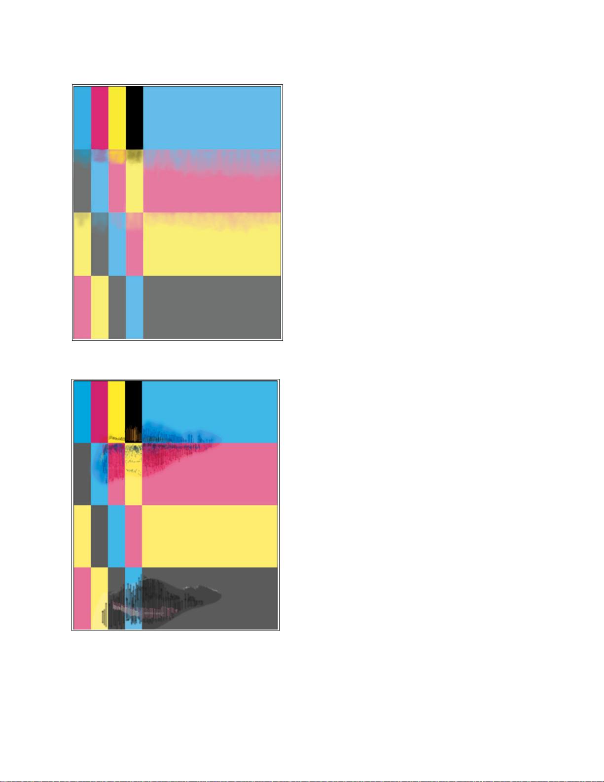
Test Patterns
Contamination of one color by another color
This is most noticeable on solid primary fills. This is caused by a
defective photoconductive belt cleaning belt. The blade is not
scraping off all of the untransferred toner from the previous pass
of the photoconductive belt to the accumulator belt prior to the
next toner’s transfer to the photoconductive belt. Replacing the
imaging unit corrects this problem.
B
Large smeared areas in the print
This is usually caused by the accumulator belt slipping on its
rollers. Replacing the imaging unit solves this problem.
Service Manual
B-3
Page 42

Test Patterns
Single light, horizontal line in all the prints
This is probably caused by a defective photoconductive belt onto
which toner will not transfer. Replace the imaging unit.
B
Large, random light smudges
Spots such as those illustrated are caused by fingerprints on the
photoconductive or accumulator belt. Often the smudges will
gradually fade with additional printing. Alternately, the imaging
unit will have to be replaced.
Service Manual
B-4
Page 43
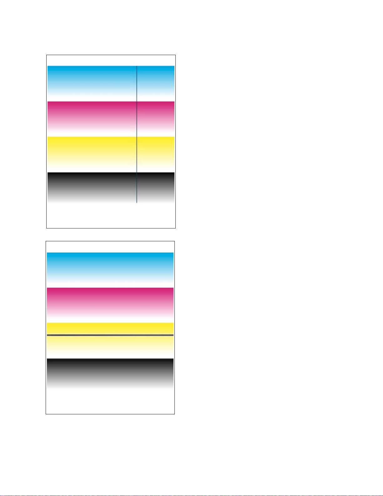
Test Patterns
One or more dark vertical line in all colors
This can often be traced to a dirty scorotron charger corona wire.
Contamination (dust or toner) interferes with the flow of electrons
from the wire to the photoconductive drum. Toner is then
transferred to the area of low electron charge and consequently
to the accumulator belt and finally the print. Remove the
scorotron charger from the imaging unit and clean the charger’s
corona wire. Alternately, replace the imaging unit.
B
Single, dark line near bottom of print
This is called a fuser stall. It is usually caused when the sheet of
paper does not smoothly enter the fuser but momentarily stops,
allowing the transfer roller (which is still transf erring toner from the
accumulator belt to the paper) to transfer too much toner to the
momentarily stalled paper. Fuser stalls are usually caused by
excessively curled paper that does not properly enter the fuser
rollers. Also ensure that there are no obstructions in the paper
path.
Service Manual
B-5
Page 44
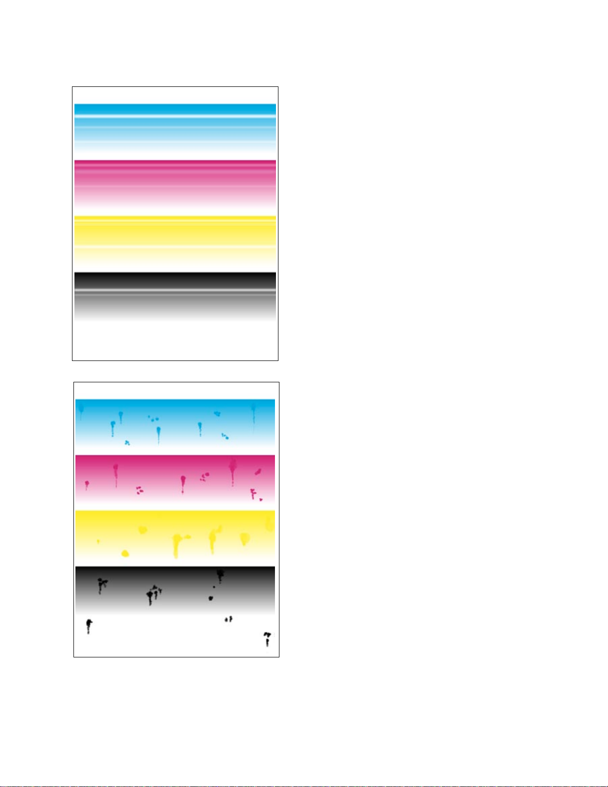
Test Patterns
Multiple, light, random horizontal lines.
In all colors This is usually traced to a poor electro-mechanical
connection to the second bias transfer roller. The fluctuating
voltage to the transfer roller is causing irregular toner transfer to
the paper. Clean the roller contacts or replace the transfer roller
or the paper feeder.
In a single color This is usually traced to a poor
electro-mechanical connection to the particular toner cartridge.
The fluctuating voltage to the developing roller of the toner
cartridge is causing irregular toner transfer to the paper. Clean
the roller contacts or replace the toner cartridge or the toner
cartridge bias assembly.
B
Blobs, spots, and streaks in all colors
The photoconductive belt cleaning blade is not properly cleaning
the photoconductive belt. Replace the imaging unit
Service Manual
B-6
Page 45
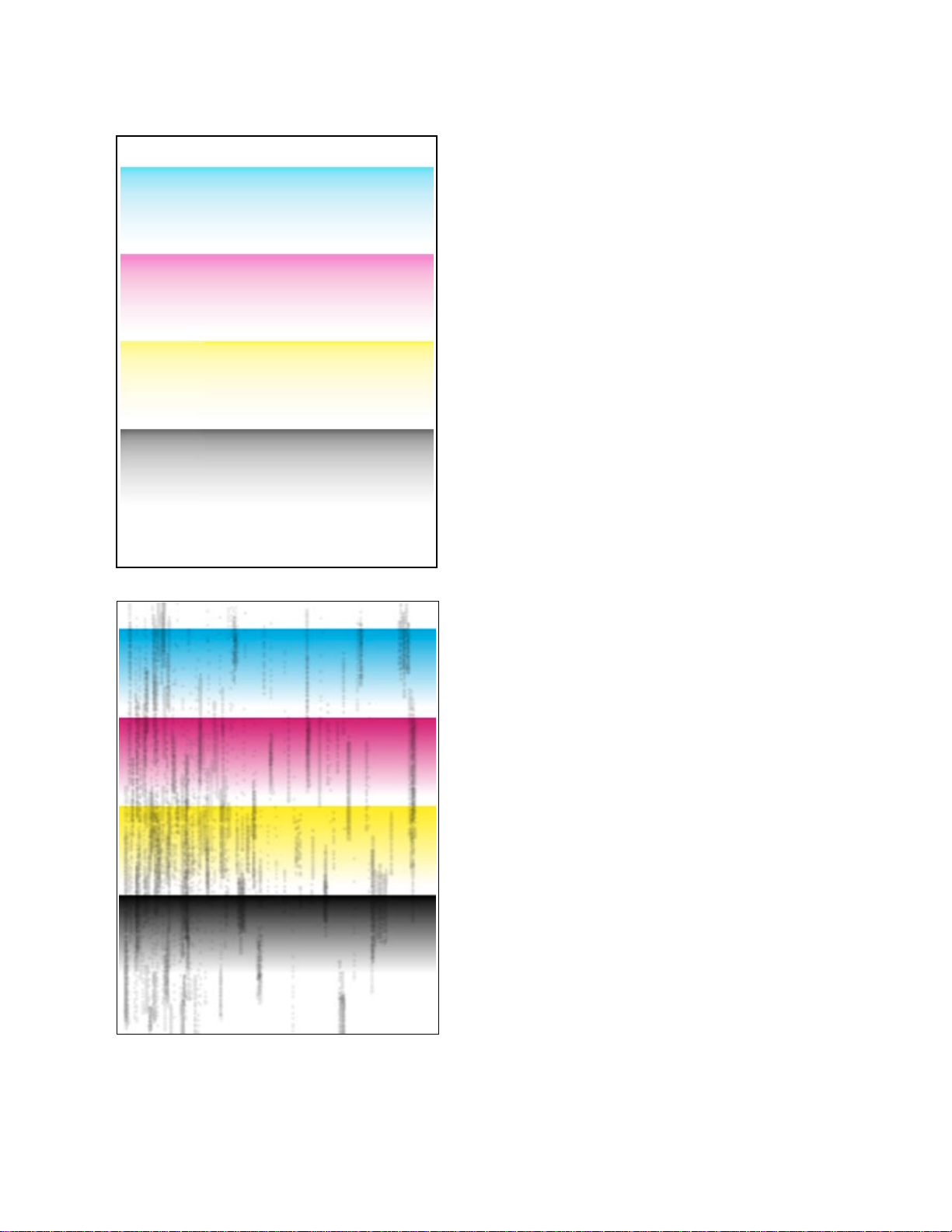
Test Patterns
Faded, pale prints
The imaging unit is old or has been exposed to too much room
light. Replace the imaging unit.
The image density sensors are not properly measuring the
amount of toner transferred to the accumulator belt. Clean or
replace the sensors.
The high-voltage board is not outputting sufficient voltage to the
second bias transfer roller, causing poor transfer of toner to
paper. Likewise, low voltage to the toner cartridge will cause
insufficient transfer of toner to the photoconductive belt.
The beam from the laser scanner is weak and is not properly
exposing the photoconductive belt. Poor laser exposure results in
the negative charges remaining on the drum instead of being
“erased” by the laser beam, thereby retarding toner transfer from
the toner cartridges. Replace the laser scanner.
B
Dark, vertical streaks and smears on the entire page
This is usually due to the accumulator belt toner waste bin being
filled and spilling out on the belt. The spilled toner is then being
transferred to the print. A defective cleaning blade could also
cause this. In either case, replacing the imaging unit should fix
the problem.
Service Manual
B-7
Page 46
Test Patterns
One primary color faded or pale
This indicates a problem with a single toner cartridge. Replacing
the toner cartridge should fix the problem.
If it does not, there may be a problem with the toner cartridge
selector/eject unit. It may not be pushing the cartridge quite far
enough to make proper contact with the photoconductive belt,
resulting in poor toner transfer. Replace the toner cartridge
selector/eject unit.
Lastly, poor electro-mechanical contact my be the problem,
although this usually shows itself as light, horizontal streaks and
lines. Replace the toner cartridge biasing assembly.
B
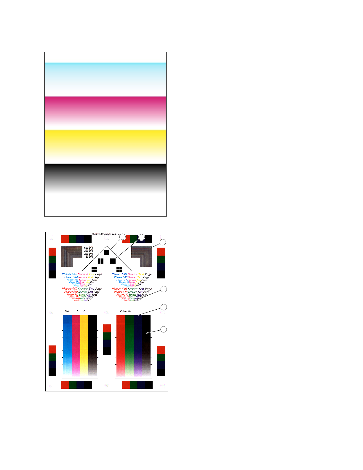
Interpreting Service Print 1
1
2
3
4
5
6
9013-60
Service Print 1, which is printed in 600 dpi, is useful for evaluating
the condition of the imaging unit. With a properly functioning
imaging unit and printer, you should see the following:
1. Diagonal lines. These two lines should be smooth and
unbroken.
2. Crosshairs. A thin white crosshair should be visible in each
block square.
3. 600 dpi parallel lines. Distinct parallel lines, both horizontal
and vertical, should be viewable. No mottling or blending
should be seen. All vertical lines should be identical in
appearance and thickness to their horizontal counterparts.
4. 2 pt. text. The 2point te xt, the smallest printed on the test print,
should be easily readable.
5. Registration. The top edges of each side-by-side solid fill
should line up with each other.
6. Blended fills. The fills should be smooth and e v en in both the
primary and secondary color fills.
Service Manual
B-8
Page 47
Test Patterns
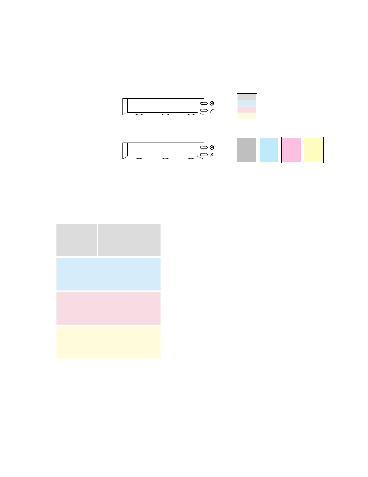
Phaser 540 Plus test prints.
The Test Print produced by the Phaser 540 Plus differ
from those produced by the Phaser 540. Test Print consists of four 25% tint
primary color bands. Service Print 1 prints out four 25% tint full page fills, each
page one primary color. Service Print 2 shows 300 dpi printing.
From the Help Pages menu in the front panel, select Test Print
Test Print
<--- ---> Print
Power
Error
From the Help Pages menu in the front panel, select Service Print 1
Service Print 1
<--- ---> Print
Power
Error
Black
Cyan
Magenta
=
Yellow
Imaging Unit XXXX
Corona Wire XXXX
Test Print
Transfer Kit XXXX
Fuser XXXX
=
Black Cyan Magenta Yellow
B
Vertical line or scratch in print, single color
If the scratch is of one missing primary color, then the trouble can
usually be traced to a scratch in the developer roller of the
missing toner’s toner cartridge. No toner is transferred from the
developer roller to the photoconductive belt at the defect point.
Vertical line or scratch in print, all colors
The problem may be caused by contamination on the laser
window where the laser beam exits the laser scanner and enters
the imaging unit. Since the b loc k ed laser beam cannot discharge
the portion of the photoconductive belt it cannot reach, toner will
not transfer to those portions of the belt. Consequently a blank,
vertical line will appear on the prints in all colors. Remove the
imaging unit and, with a squeeze bulb, blow any dust or toner off
of the window (located in the “ceiling” of the cavity left in the
printer once the imaging unit is removed).
If it is in all colors then the problem may be in the imaging unit,
which replacing will solve.
It could also be a scratched roller in the fuser which replacing will
solve.
Lastly a protrusion of some kind in the paper path could be
scratching the print.
Service Manual
B-9
Page 48

Test Patterns
Small, repeating light dot in one color
This can usually be traced to a dent-like defect in the developer
roller of the toner cartridge in question. No toner is transferred
from the developer roller to the photoconductiv e belt at the defect
point.
B
Light, wavy, vertical streaks in all colors
This is caused by contamination on the pre-transfer charger
corona wire. The contamination (usually toner) interf eres with the
flow of electrons from the wire to the toner on the accumulator
belt. With the toner on the belt being unevenly charged, it
transfers unev enly to the paper. Cleaning the corona wire usually
fixes this problem.
Service Manual
B-10
Page 49

Test Patterns
Single light, horizontal line in all the prints
This is probably caused by a defective photoconductive belt onto
which toner will not transfer. Replace the imaging unit.
B
Large, random light smudges
Spots such as those illustrated are caused by fingerprints on the
photoconductive or accumulator belt. Often the smudges will
gradually fade with additional printing. Alternately, the imaging
unit will have to be replaced.
Service Manual
B-11
Page 50

Test Patterns
One or more dark vertical line in all colors
This can often be traced to a dirty scorotron charger corona wire.
Contamination (dust or toner) interferes with the flow of electrons
from the wire to the photoconductive drum. Toner is then
transferred to the area of low electron charge and consequently
to the accumulator belt and finally the print. Remove the
scorotron charger from the imaging unit and clean the charger’s
corona wire. Alternately, replace the imaging unit.
B
Faded, pale prints
The imaging unit is old or has been exposed to too much room
light. Replace the imaging unit.
The image density sensors are not properly measuring the
amount of toner transferred to the accumulator belt. Clean or
replace the sensors.
The high-voltage board is not outputting sufficient voltage to the
second bias transfer roller, causing poor transfer of toner to
paper. Likewise, low voltage to the toner cartridge will cause
insufficient transfer of toner to the photoconductive belt.
The beam from the laser scanner is weak and is not properly
exposing the photoconductive belt. Poor laser exposure results
in the negative charges remaining on the drum instead of being
“erased” by the laser beam, thereby retarding toner transfer from
the toner cartridges. Replace the laser scanner.
Service Manual
B-12
Page 51
Test Patterns
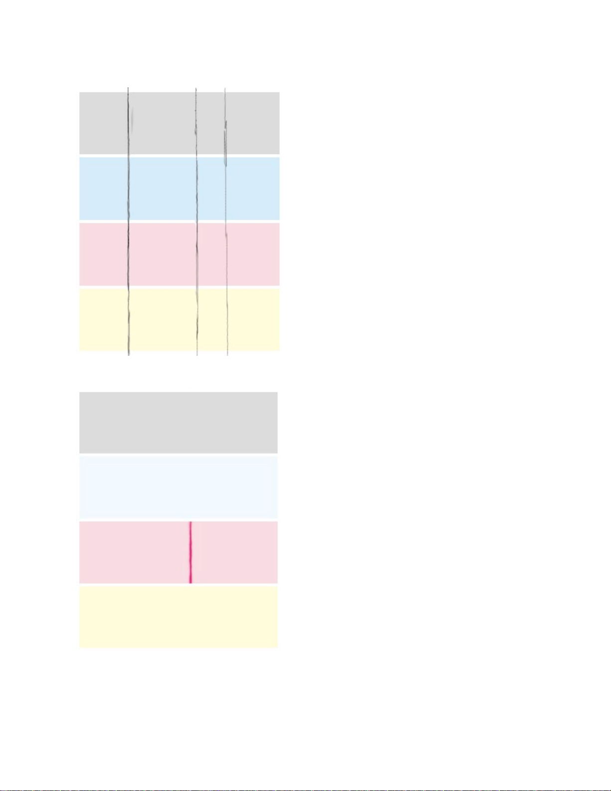
Dark, vertical streaks and smears on the entire page
This is usually due to the accumulator belt toner waste bin being
filled and spilling out on the belt. The spilled toner is then being
transferred to the print. A defective cleaning blade could also
cause this. In either case, replacing the imaging unit should fix
the problem.
B
One primary color faded or pale OR a single color has a dark
vertical streak
This indicates a problem with a single toner cartridge. Replacing
the toner cartridge should fix the problem.
If it does not, there may be a problem with the toner cartridge
selector/eject unit. It may not be pushing the cartridge quite far
enough to make proper contact with the photoconductive belt,
resulting in poor toner transfer. Replace the toner cartridge
selector/eject unit.
Lastly, poor electro-mechanical contact my be the problem,
although this usually shows itself as light, horizontal streaks and
lines. Replace the toner cartridge biasing assembly.
Service Manual
B-13
Page 52

Test Patterns
Single white spot appear in the same place on the print
This indicates a bad spot has developed on one of the the
imaging unit’s belt which will not trasfer toner. The imageing unit
must be replaced.
B
Interpreting Service Print 2
1
2
3
4
5
6
9013-60
Service Print 2 is useful for evaluating the condition of the
imaging unit. With a properly functioning imaging unit and printer ,
you should see the following:
1. Diagonal lines. These two lines should be smooth and
unbroken.
2. Crosshairs. A thin white crosshair should be visible in each
block square.
3. 300 dpi parallel lines. Distinct parallel lines, both horizontal
and vertical, should be viewable. No mottling or blending
should be seen. All vertical lines should be identical in
appearance and thickness to their horizontal counterparts.
4. 2 pt. text. The 2point te xt, the smallest printed on the test print,
should be easily readable.
5. Registration. The top edges of each side-by-side solid fill
should line up with each other.
6. Blended fills. The fills should be smooth and e v en in both the
primary and secondary color fills.
Service Manual
B-14
Page 53
A
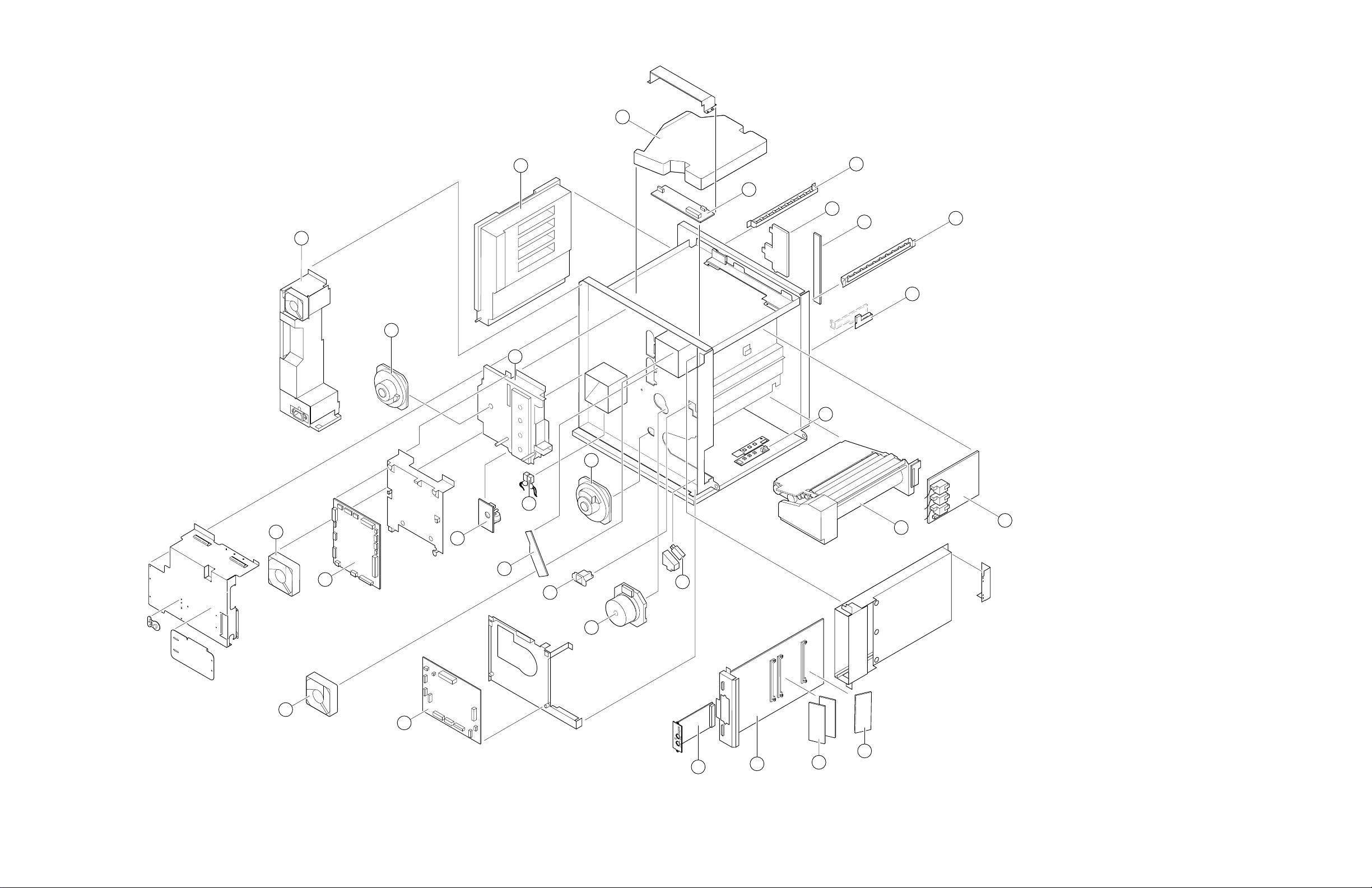
Figure A-3 The internal printer
7
6
8
4
5
28
25
9
10
11
13
14
12
26
3
2
1
20
27
24
23
22
21
29
19
18
17
15
16
9013-56
Service Manual
A-5
Page 54

A
Table A-4 Supplies and accessories
Part number Serial number
Effective Discontinued
Supply 016-1316-00 Imaging unit
Supply 016-1323-00 Fuser (110 VAC)
Supply 016-1354-00 Fuser (220 VAC)
Supply 016-1317-00 Pre-transfer charger (corona wire kit)
Supply 436-0282-00 Paper tray, Letter-size
Supply 436-0283-00 Paper tray, A4-size
Supply 436-0284-00 Transparency tray, Letter-size
Supply 436-0285-00 Transparency tray, A4-size
436-0314-00 Paper tray, Legal-size
436-0297-00 Output tray
119-4799-00 Lower Tray Assembly (no trays supplied)
070-9008-01 Phaser 540 User Manual (English)
070-9008-11 Phaser 540 User Manual (French)
070-9008-21 Phaser 540 User Manual (Italian)
070-9008-31 Phaser 540 User Manual (German)
070-9008-41 Phaser 540 User Manual (Spanish)
070-9009-00 Phaser 540 Drivers and Utilities Printing
070-9109-00 Network Manual
070-9291-00 Phaser Share Administation Manual
070-9292-00 Phaser Share Status Monitor Manual
070-9013-01 Phaser 540 Service Manual
063-2179-00 Ethernet Network Software Kit
Quantity Name and description
Reference Manual
Table A-4 Supplies and accessories (cont'd.)
Part number Serial number
Effective Discontinued
016-1326-00 Transparency, Metric-size, 50 sheets
016-1368-00 Paper, A-size, 500 sheets
016-1369-00 Paper, A4-size, 500 sheets
013-0297-00 Adapter, Cable
103-0030-00 Adapter, Connector, BNC
011-0123-00 Coaxial Term. 50 ohms, BNC
016-1319-00 Black toner cartridge
016-1320-00 Cyan toner cartridge
016-1321-00 Magenta toner cartridge
016-1322-00 Yellow toner cartridge
161-0066-00 Power cord, domestic
161-0066-09 Power cord, 220V Euro
161-0066-10 Power cord, U.K.
161-0066-11 Power cord, Australian
161-0154-00 Power cord, Swiss
334-8366-22 Logo - Phaser 540
334-8366-32 Logo - Phaser 540 Plus
016-1318-00 Transfer Kit (Transfer roll and Waste box)
118-9070-00 Scorotron charger corona unit
006-7998-00 Conductive grease
118-9175-00 Pre-transfer corona cleaning tool
006-7971-00 Imaging unit light shield/drape
Quantity Name and description
A-6
063-2181-00 LocalTalk Network Software Kit
063-2089-00 Drivers and Utilities Software Kit
012-1379-00 Cable Serial, 9-pin to 9-pin
012-1299-00 Cable, interconnect., 2.5 m 50-pins. to
25-pins
012-1468-00 Cable, Parallel w/IEEE 1284C (mini)
012-1465-00 Cable, SCSI II to 50-pin SCSI
012-1380-00 Cable, Serial, 9-pin to 25-pin
013-0299-00 Parallel cable adapter (standard to mini)
003-1496-00 Toner Vacuum (115 VA C)
003-1497-00 Toner Vacuum (220 VA C)
003-1498-00 Filter for 3M Toner Vacuums
016-1325-00 Transparency, Letter-size, 50 sheets
Phaser 540 Color Printer
Page 55

Appendix
A
Field Replaceable
Units List
This appendix provides a list of field replaceable units for the printer.
Changes to Tektronix instruments are made to accommodate improved
components as they become available. It is important when ordering parts to
include the following information:
■
Component's part number.
Instrument type or number.
■
■
Instrument serial number.
■
Modification number, if any.
Service Manual
A-1
Page 56
Field Replaceable Units List
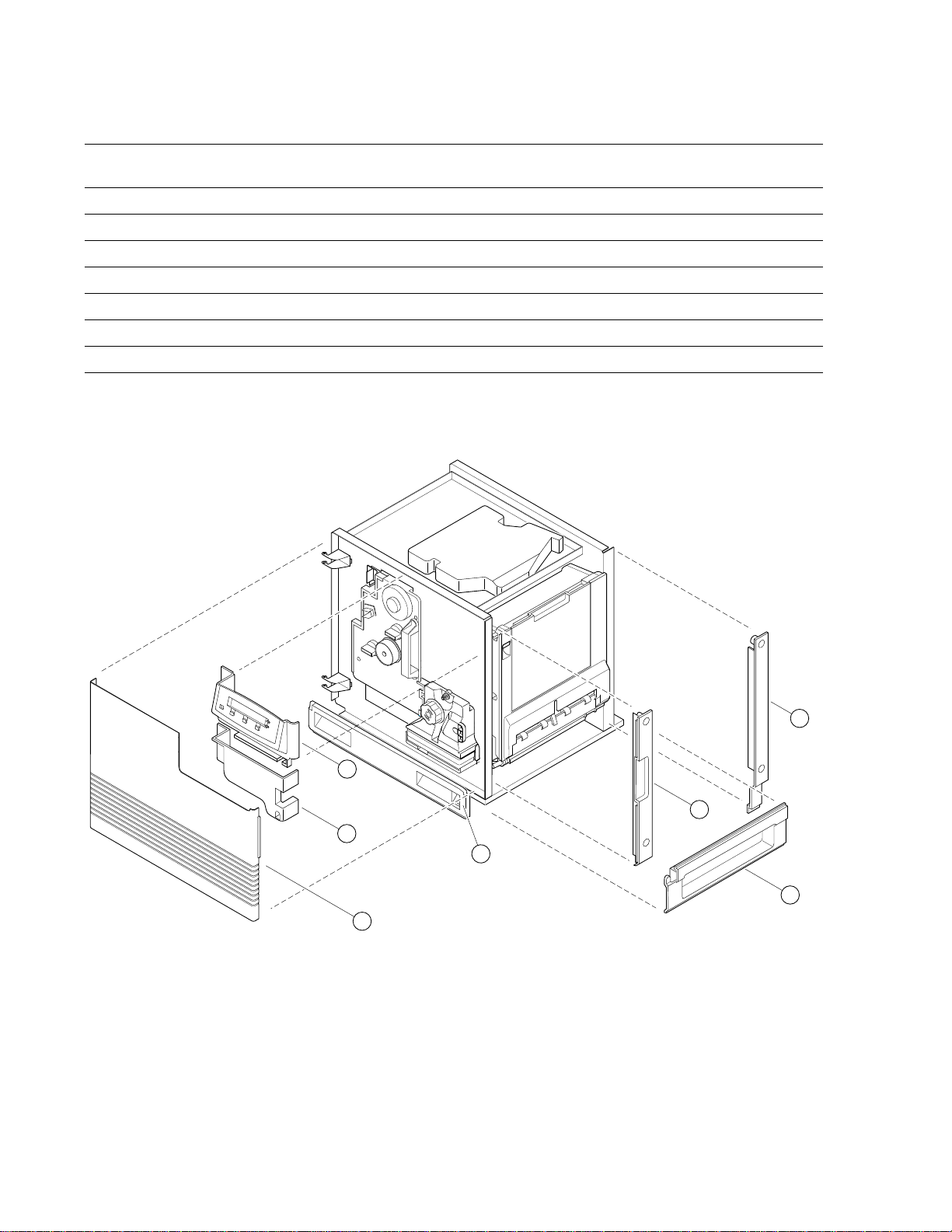
A
Table A-1 FRU parts list of the printer cabinet
Figure
A-1
1 118-9205-00 1 Front door
2 118-9204-00 1 Lower front cover
3 118-9203-00 1 Upper front cover w/display board
4 118-9206-00 1 Right side cover rear
5 118-9208-00 1 Right side cover front
6 118-9207-00 1 Right side cover lower
7 118-9182-00 1 Bottom front cover
Part number Serial number
Effective Discontinued
Quantity Name and description
Figure A-1 Cabinet FRUs
A-2
Phaser 540 Color Printer
4
3
5
2
7
6
1
9013-44
Page 57
Field Replaceable Units List
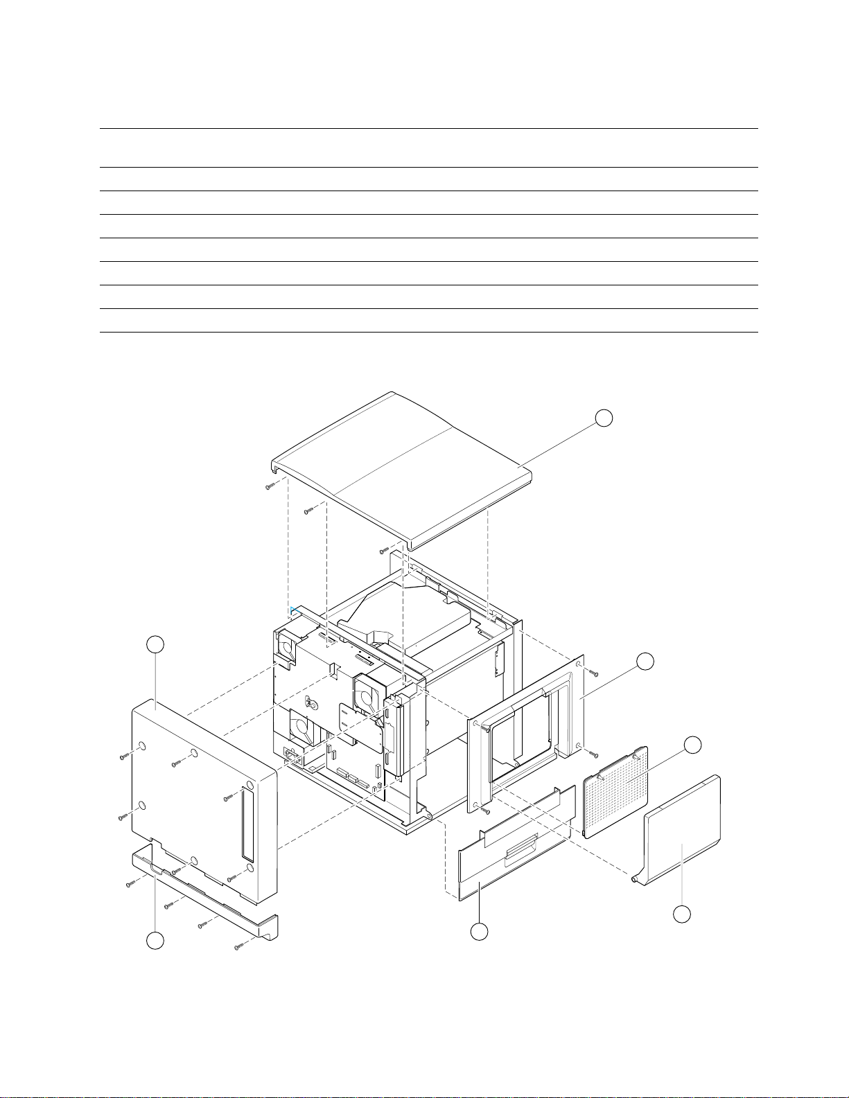
Table A-2 FRU part list of the printer cabinet
Figure
A-2
1 118-9202-00 1 Lower rear cover
2 118-9201-00 1 Upper rear cover
3 118-9198-00 1 Top cover
4 118-9200-00 1 Left side cover
5 118-9199-00 1 SIMM access door
6 118-9184-00 1 Manual feed tray
7 118-9183-00 1 Left door
Part number Serial number
Effective Discontinued
Quantity Name and description
3
A
2
1
Figure A-2 Cabinet FRUs
4
5
6
7
9013-45
Service Manual
A-3
Page 58

Field Replaceable Units List
A
Table A-3 FRU parts list of the exploded printer
Figure
A-3
1 118-9192-00 1 Ozone fan
2 118-9189-01 1 Engine control board
3 118-9191-00 1 Fuser/toner cartridge fan
4 118-9154-00 1 Power Supply (110 VAC)
4 118-9153-00 1 Power Supply (220 VAC)
5 118-9181-00 1 Toner cartridge drive motor
6 118-9186-00 1 Toner cartridge selector/paper-eject unit
7 118-9187-00 1 Laser scanner
8 118-9188-00 1 Laser modulation board
9 118-9166-00 1 Pre-transfer lamp
10 118-9169-00 1 Toner cartridge biasing assembly
11 118-9170-00 1 Toner level sensor board
12 118-9164-00 1 Pre-exposure erase lamp
13 118-9165-00 1 Image density sensor assembly
14 118-9167-00 1 Tray sensor board
15 118-9185-00 1 Paper feeder
16 118-9163-00 1 High-voltage board
17 671-3133-00 1 16-Mbyte RAM SIMM
18 671-3108-06 1 Image processing board w/rear panel
19 671-3468-00 1 Ethernet network card
19 671-3469-00 1 LocalTalk/serial network card
19 671-3470-00 1 Token Ring network card
20 118-9196-00 1 Engine driver board
21 118-9173-00 1 Left door-open switch
22 118-9193-00 1 Main motor
23 118-9172-00 1 Home-position sensor assembly
24 118-9171-00 1 Charger sensor board
25 118-9194-00 1 Paper feed motor
26 118-9190-00 1 Fuser installed switch
27 118-9195-00 1 Cleaning board
28 118-9168-00 1 Toner cartridge drive unit
29 671-3210-00 1 P540 PostScript Code ROM SIMM
29 671-3210-01 1 P540 Plus PostScipt Code ROM SIMM
29 671-3209-00 1 P540 PostScript Code ROM SIMM
29 671-3209-01 1 P540 Plus PostScript Code ROM SIMM
Part number Serial number
Effective Discontinued
118-9174-00 1 Hardware kit
118-9176-00 1 Gear kit
Quantity Name and description
(masked ROM - avail July ‘95)
(masked ROM - avail July ‘95)
(flash ROM - avail until July ‘95)
(flash ROM - avail until July ‘95)
A-4
Phaser 540 Color Printer
Page 59

Chapter
9
Checks and Adjustments
This chapter discusses using the front panel’s interactive mode to review and
change the printer’s operation. It also contains the procedures to calibrate the
printer after you replace key Field Replaceable Units and to evaluate the
printer's functionality.
Required tools
■
■
Magnifying lens (preferably illuminating)
Phillips screwdriver
Service Manual
9-1
Page 60
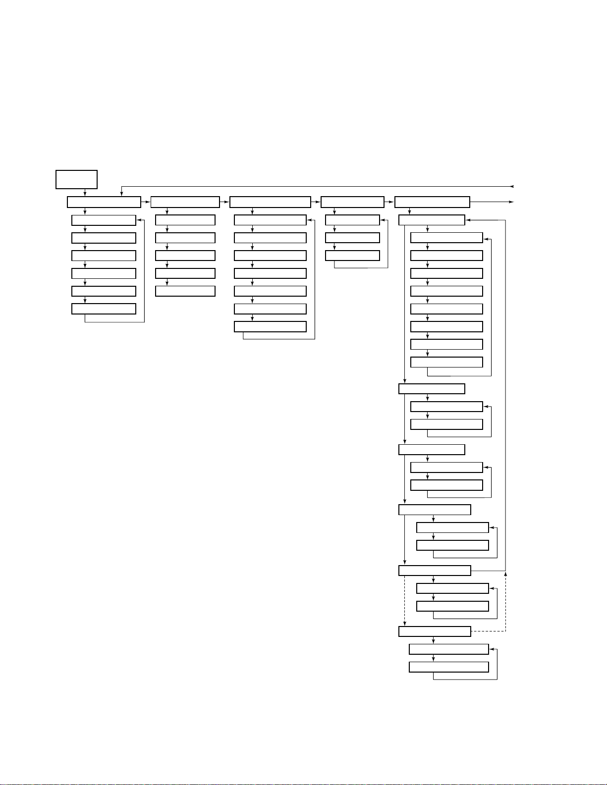
9
Checks and Adjustments
Front panel menu
The print engine features an interactive front panel menu that allows you to
review or change the printer’s stored parameters as well as initiate test prints
and printer service routines. When the front panel displays
to enter the printer’s interactive menu.
Idle
Menu
Ready , p ress Menu
Test Page
Demonstration Pages
Startup Page
Configuration Page
Service Print 1
Service Print 2
Menu Map
System counts menu
Page count
Imaging Unit
Corona Wire
Transfer Kit
Fuser
TekColor Correction menu
TekColor: None
TekColor: None
TekColor: Vivid Color
TekColor:Display
TekColor: SWOP
TekColor: Euroscale
TekColor: Commercial
Monochrome
Print Quality menu
Standard
Enhanced
Fast
Printer defaults menu
Default tray
Upper
Middle
Lower
Media Tray
Manual Feed
Paper
Transparency
Auto Select
Startup Page
Startup Page: enabled
Startup Page: disabled
Startup Mode
Startup Mode: enabled
Startup Mode: disabled
Figure 9-1 Menu map
9-2
Phaser 540 Color Printer
Output order
Output order: face up
Output order: face down
Energy Star
Energy Star: enabled
Energy Star: disabled
Energy Star timeout
Energy Star timeout: xxx hrs
Timeout: xxx hrs
9013-54
Page 61
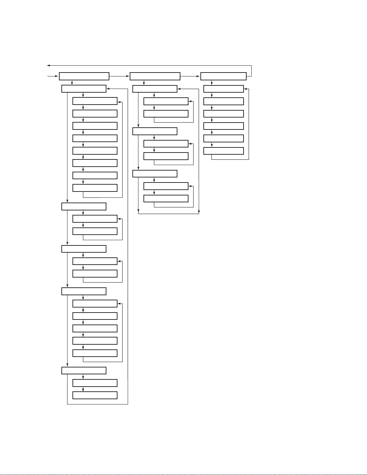
Serial settings
Baud Rate
Baud Rate: 300
Baude Rate: 600
Baud Rate: 1200
Baud Rate: 2400
Baud Rate: 4800
Baud Rate: 9600
Baud Rate: 19200
Baud Rate: 38400
Network settings
TCP/IP
TCP/IP: enabled
TCP/IP: disabled
Ether Talk
Ether Talk: enabled
Ether Talk: disabled
Novell
Novell: enabled
Language menu
Language: English
Language: Español
Language: Français
Language: Deutsch
Language: Italiano
Language: Japanese
Checks and Adjustments
9
Data Bits
Data Bits: 7
Data Bits: 8
Stop Bits
Stop Bits:1
Stop Bits: 2
Parity
Flow Control
Novell: disabled
Even
Odd
Mark
Space
None
Xon/Xoff
dtr
Figure 9-2 Menu map
9013-55
Service Manual
9-3
Page 62

1.
2.
1.
2.
1.
2.
1.
Checks and Adjustments
9
Printing test prints
The prints printed via the front panel the are generated by the image processor.
While the printer is idle you can use the front panel to print a configuration page
which is an image stored in the image processor.
Print service test prints
The service prints allow you to evaluate the printer’s print quality. Service
Print 1 four pages of 25% tint primary color fills. Service Print 2 is printed in 300
dpi.
Press the Menu button.
With the Help pages menu displayed, scroll to the Service
Print 1
or Service Print 2 menu item. Press Print .
Printing the configuration page
The configuration page shows a great deal of information regarding the data
and set-up values stored in NVRAM. Refer to the topic, “The configuration
page” on page 2-14 for an explanation of the configuration page.
Press the Menu button.
With the Help pages menu displayed, scroll to the Configuration
menu item. Press Print .
Page
Printing the demonstration pages
Demo pages demonstrate the capabilities of the printer.
Press the Menu button.
With the Help pages menu displayed, scroll to the Demonstration
item. Press Print .
Page
Printing the print engine’s test print
The print engine can print a test print independent of the image processor. The
print is a composite gray fill composed of cyan, magenta and yellow toner. No
black toner is used in the print.
9-4
Press and hold for 2 seconds the Test Print button in the center of the
upper rear cover.
This verifies the print engine’s ability to print independent of the image
processor.
Phaser 540 Color Printer
Page 63

on
Image processor normal indicators
There are three indications that the print engine and its image processor are
powered-up and operating normally: the front panel POWER LED is on
(steady),
processor health light is blinking (the flashing health light is viewable through
the grill behind the manual feed tray).
When the printer is receiving or processing data, the front panel displays the
messages
for Data
Ready is displayed on the front panel LCD display and the image
Receiving Data and Processing Data . The message Waiting
may also be displayed periodically.
Image processor hard and soft error indicators
Image processor hard errors are self-test failures that would prevent the printer
from printing a page. Hard errors cause the health light to stop blinking and
remain
Soft errors are errors that occur during the normal power-up self-test that, while
limiting the printer, would not stop the printer from printing. A message
regarding the soft error would then be printed on the startup page (even if the
startup page had been turned off). Soft errors include failures of the expansion
SIMMs, as well as the SCSI, serial, LocalTalk, parallel, and Ethernet ports.
or off . Hard errors are also any error that occurs during service mode.
Checks and Adjustments
9
Service Manual
9-5
Page 64

Checks and Adjustments
9
Printer self-diagnostics
The printer’s image processor features four types of self-test modes. The type of
self-tests run depend upon which front panel buttons are pressed while the
printer is turned on. The button combinations are listed here.
■
Turning on the printer or restarting the printer remotely executes
normal image processor power-up self-tests and then, if the tests pass,
proceed to launch its PostScript interpreter.
Pressing and holding Button 1 (the left-most button, marked Exit), as
■
you turn on the printer, skips the image processor’s self tests and
proceed directly to launching its PostScript interpreter.
■
Pressing and holding Button 2 (the second from the left button), as
you turn on the printer, executes the image processor’s verification
self-tests. These series of test continue until the printer is turned off.
Pressing and holding Button 3, as you turn on the printer, executes
■
interactive service test with the image processor board and the print
engine.
■
Pressing and holding Button 1 and 4, as you turn on the printer, allows
you to reset the NVRAM to its factory-default values. Refer to the
later topic, “Resetting NVRAM” on page 9-9.
Normal power-up self-tests.
a problem is encountered with the image processor's expansion memory or
other options, then the information is printed on the printer's startup page.
Normal power-up tests take slightly longer than one minute to complete.
The health LED, located on the image processor board, flashing in a regular, one
flash-per-second rate means
CPU is running.
Kernel tests.
then, if no error occurs, goes directly to PostScript initialization.
Verification test.
all host cables from the printer before starting the test. A fully configured
printer takes slightly longer that 3 minutes to execute the tests. The image
processor continuously executes a series of tests of its CPU kernel, RAM and
other image processor components. The series of tests run continuously until an
error occurs. The printer continuously loops on that test indicating the number
of times the test passed and failed. The printer must be turned off to exit the test
series.
The printer’s image processor executes its core set of CPU tests and
This test requires no paper or customer interaction. Disconnect
This test requires no paper or customer interaction. If
no errors were detected and the image processor's
9-6
Phaser 540 Color Printer
Page 65

Checks and Adjustments
Service tests.
Service tests include all the available image processor self-tests.
with the addition of some test prints and also being able to interact with the
print engine motors, solenoids and sensors. You select and start tests using the
front panel. The message
Service Tests is displayed on the top line of the
front panel when the service tests are activated and running. If no error is
detected, the front panel displays
Ready and the image processor enters its
operational mode. If an error is detected, the front panel displays the failing test.
Using the front panel buttons, scroll to an individual test and run it. In service
mode, you can also scroll to a set of tests that allow you to start a single print or
to print continuously. These are the service tests options:
All tests
■
■
Test groups
Kernel
■
DRAM
■
I/O
■
9
PWA (image processor board)
■
Test prints
■
■
Engine diagnostics (interactive)
Engine firmware version (this value is also printed on the startpage)
■
Engine status — loop on any engine status byte and see the byte
■
change in real-time.
Engine sensor states — indicates the real-time state of the displayed
■
sensor; this allows you to test the sensors in real time by manually
interrupting them.
■
Fuser
Pre-transfer
■
charger
Scorotron
■
charger
■
Paper pick
sensor
(registration
sensor)
■
■
■
■
Fuser exit
sensor
Paper exit
sensor
Tray type
sensors
Toner full
sensors
■
Manual feed
sensor
Paper empty
■
sensor
Transparency
■
film sensor
■ T oner cartridge
missing sensor
■
T oner cartridge
cam position
sensors
Transfer roller
■
position sensor
Cleaning
■
blade position
sensor
■ Paper low
sensor
■ Paper jam
(fuser entry
sensor
■ Outputs tray
full sensor
■ Door open
interlock
sensor
■ Belt home
position
sensors
Service Manual
9-7
Page 66

9
Checks and Adjustments
■ Motor exercise — turns on the following motors for 2 seconds and then
off.
■ Main motor ■ Toner cartridge drive
■ Fans
motor
■ Paper feed motor ■ Laser scanner motor ■ Toner cartridge
selector cam motors 1
through 4
■ In addition, through this group of tests, you can exercise the following
parts:
■ Toner cartridge
developer rollers
■ Registration clutch ■ Transfer rollers
■ Fuser temperature — displayed in Celsius.
■ Print engine NVRAM contents — which can be viewed, changed or
■ Pick rollers ■ Cleaning blade
(accumulator belt)
reset.
■ Top margin values ■ Imaging unit page
count
■ Left margin value ■ Pre-transfer charger
page count
■ Fuser page count
■ Print engine page
count
■ Paper path exercise — pick and move a sheet of paper through the
paper path. Single-sheet pick or continuous-pick. Cycles through the
installed trays.
9-8
Phaser 540 Color Printer
Page 67

Resetting NVRAM
Resetting NVRAM returns all the image processor's NVRAM-stored parameters
to their factory defaults except the print counts and the Adobe firmware serial
number.
To reset the image processor to its factory default values, follow this procedure:
1.
Turn the printer off.
2.
Press and hold the front panel Buttons 1 (Exit) and 4.
3.
Turn the printer on.
4.
When the front panel displays the message NVRAM Default, release
Buttons 1 and 4.
5.
At this point the message password? will be displayed. Within
10 seconds, press Buttons 1 (Exit) and 3 at the same time. The
NVRAM parameters will be reset to their factory default values. If
you do not press buttons 1 and 3 in the allotted time, the NVRAM will
not be changed.
Checks and Adjustments
9
Service Manual
9-9
Page 68
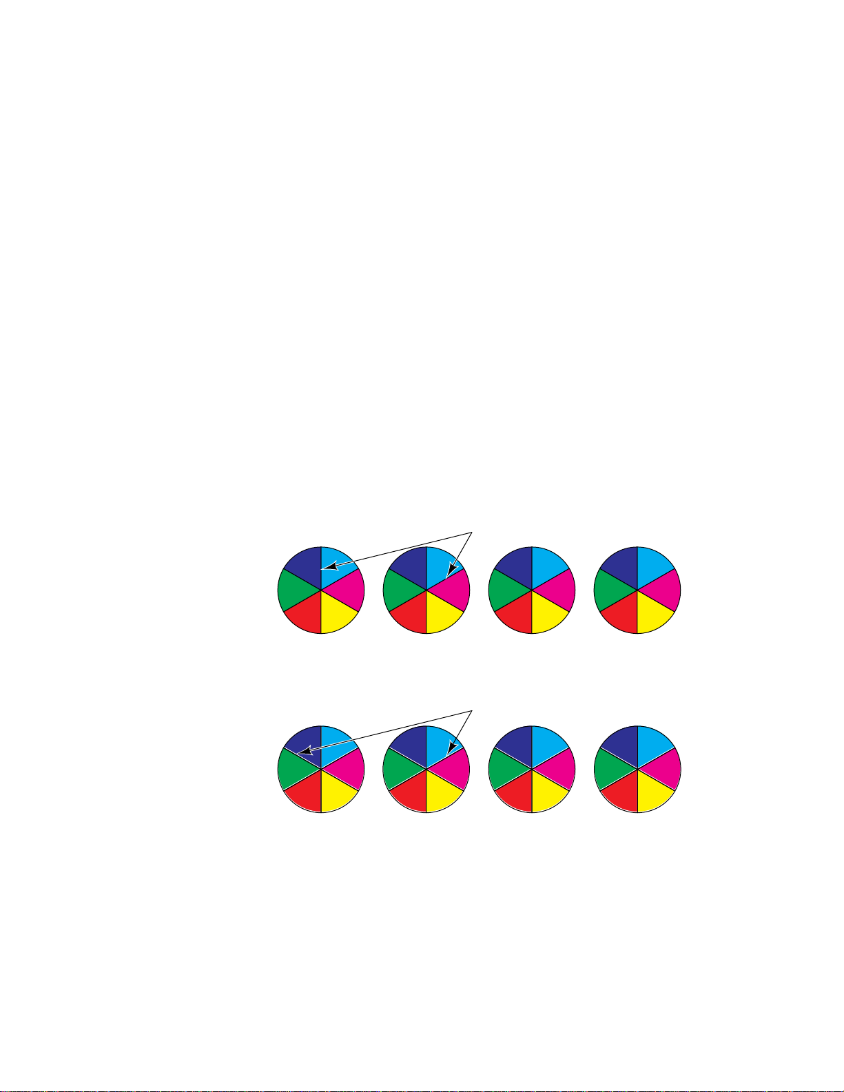
9
Checks and Adjustments
Print engine calibration
Generally, no print engine calibration is required. Using its closed-loop, image
density sensors, the printer can auto-calibrate its color output. Usually, if you
note a print defect, replacing a toner cartridge, the imaging unit or the transfer
roller (or perhaps the paper feeder) corrects the problem.
Checking print registration
A simple way to determine if the printer is properly registering the layers of
toner is to print and examine the Startup Page.
1.
Press the Menu button.
2.
With the Help pages menu displayed, scroll to the Startup Page
item. Press Print.
Examine the four six-color pies at the bottom of the print. You should see no
white areas bordering the black lines separating the color slices. If you do, the
printing is misregistered and the imaging unit should be replaced. Also clean
the accumulator belt home position sensor.
TekColor Corrections
None Vivid Color Display Press Match
TekColor Corrections
None Vivid Color Display Press Match
Figure 9-3 Checking the registration of the toner layers
No white next to black printing
good resgistration
White seen next to blackprinting
poor registration
9013-57
9-10
Phaser 540 Color Printer
Page 69

Chapter
8
FRU
Disassembly/Assembly
This chapter explains how to remove and replace many of the printer's Field
Replaceable Units (FRUs). This chapter covers procedures for FRUs that are
difficult to remove or require special handling or precautions. Refer to
Appendix A for a list of the printer's FRUs.
Required tools
■
■
■
Magnetic tip screwdrivers; 3-inch shaft and 6-inch shaft:
■
#1 POSIDRIV
Needle-nose pliers
Diagonal cutters
tip — extended shank
■
Replacement cable ties 343-0549-00
Flat-blade screwdriver
■
■
95% isopropyl alcohol
■
Antistatic mat 006-7056-00
Service Manual
8-1
Page 70

1.
1.
1.
2.
3.
1.
2.
3.
4.
1.
2.
1.
FRU Disassembly/Assembly
8
The printer cabinet
Upper rear cover
Remove the six screws securing the upper rear cover in place.
Lower rear cover
Remove the four screws securing the lower rear cover in place.
Top cover
Remove the upper rear cover first.
Remove the three screws securing the rear of the top cover in place.
The front of the top cover is held by metal tabs. Tilt the cover up from
the rear, slide it back slightly and remove.
Left door (for paper feeder access)
Open the left door.
Unhook the retaining strap from the door.
Unpin the two hinge spring arms (black plastic). Each is located at
the ends of the door.
Unpin the door from the engine frame. Unpin the rear of the door
first.
Left side cover
Lower the manual feed tray.
Remove the four screws securing the left side cover to the print
engine. Tilt forward and remove the cover.
8-2
Manual feed tray
Tilt the tray up slightly and squeeze the tray’s retaining pins inward to
free it from the print engine frame.
Phaser 540 Color Printer
Page 71
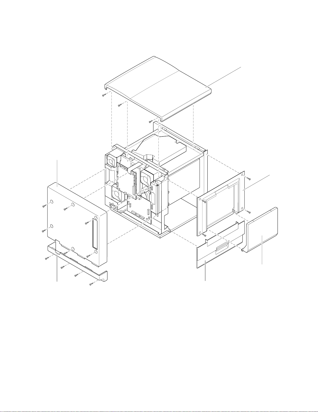
Upper rear
cover
FRU Disassembly/Assembly
Top cover
8
Lower rear
cover
Figure 8-1 Removing cabinet covers
EMI shields
Initial printers feature many metal plates and shields. Later models may have
fewer or no shields. Use a magnetic screwdriver when removing the many
screws securing EMI shields in place to avoid losing the screws in the printer.
Note the placement of the shields and the routing of all cables prior to removing
them.
Left side
cover
Manual feed
tray
Left door
9013-27
EMI shielding on the printer may change as the printer is refined.
Service Manual
8-3
Page 72

1.
2.
1.
2.
3.
4.
1.
2.
3.
1.
2.
3.
4.
1.
2.
3.
FRU Disassembly/Assembly
8
Front door
Open the front door.
Remove the two screws securing each door hinge to the front door.
Upper and lower front covers
Remove the top cover. Remove the imaging unit. Cover the imaging
unit to protect its photconductive belt from light.
Remove the four screws securing the front covers.
Disconnect the front panel board’s wiring harness.
To separate the lower front cover from the upper front cover, remove
the two screws securing them together.
Bottom front cover
Open the front door.
Remove the three screws securing the bottom front cover in place.
Tilt the cover forward and remove it.
Front panel board
Remove the top cover. Remove the imaging unit. Cover the imaging
unit to protect its photconductive belt from light.
Remove the four screws securing the front covers.
Disconnect the front panel board’s wiring harness.
Remove the four screws securing the front panel to the inside of the
upper front cover.
Toner level sensor board
Remove the top cover. Remove the imaging unit. Cover the imaging
unit to protect its photconductive belt from light.
8-4
Remove the three screws securing the toner level sensor board in
place.
Disconnect the sensor board’s wiring harness. Remove the sensor.
Phaser 540 Color Printer
Page 73
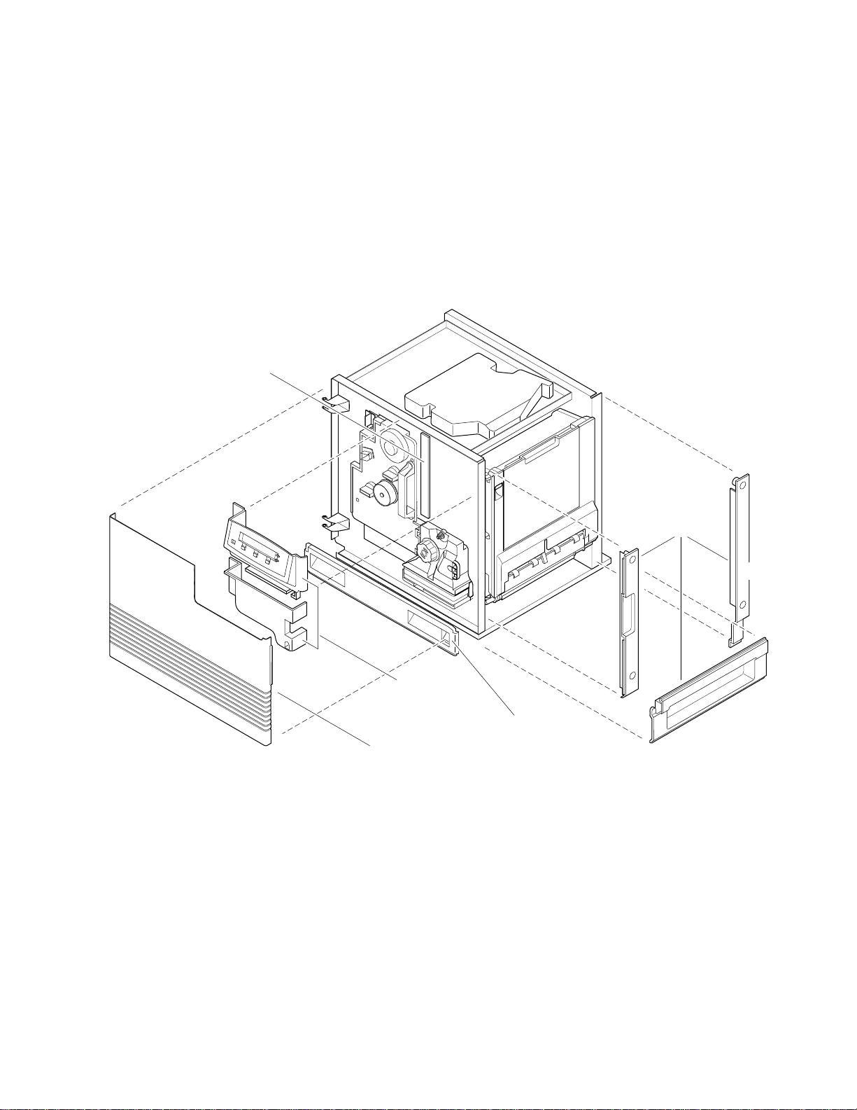
1.
2.
Right side covers (front, rear and lower)
Remove the front and rear right side covers before removing the right side lower
cover.
Remove the paper tray.
Remove the two screws securing each of the three right side cover in
place. Remove the covers. Note that the lower side cover clips
underneath the printer frame.
Toner level
sensor board
FRU Disassembly/Assembly
8
Figure 8-2 Removing cabinet covers
Upper and
lower front
cover
Front door
Bottom
front
cover
Right side
covers
Rear
Front
Lower
9013-28
Service Manual
8-5
Page 74

FRU Disassembly/Assembly
1.
2.
3.
4.
1.
2.
3.
8
Paper feeder
Turn off the printer.
Open the left side door to access the paper feeder. Slide out the paper
feeder.
With a screwdriver, back out the slide rail stop screws. There is one
screw at the end of each slide rail.
Slide the paper feeder off the rails.
Paper tray sensor board
Remove the paper feeder as explained in the previous procedure.
Remove the paper tray.
Disconnect the wiring harness leading to the paper tray sensor board.
8-6
Phaser 540 Color Printer
Page 75
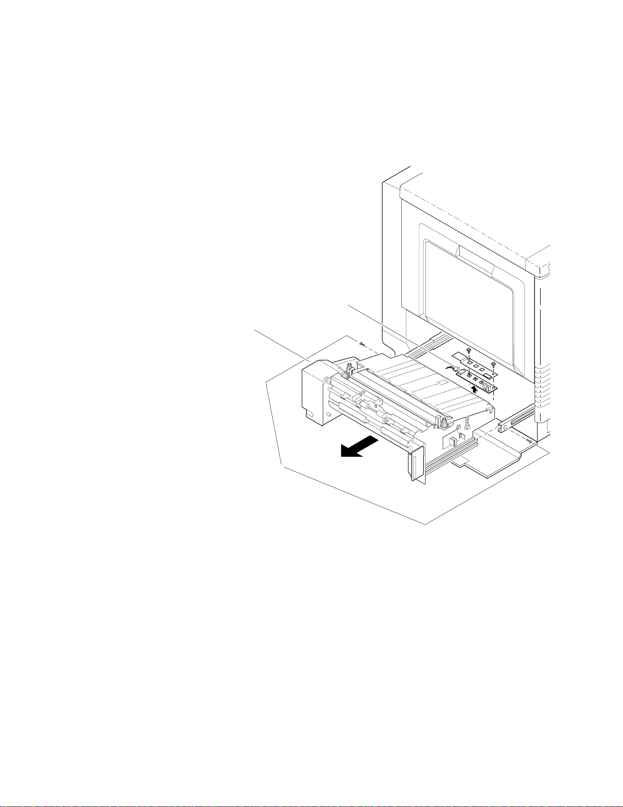
4.
FRU Disassembly/Assembly
Remove the two screws securing the sensor board to the printer. (Lift
the paper empty sensor flag out of the way while you lift the paper
tray sensor board out.)
Paper tray
sensor board
8
Paper feeder
Back-out stop
screws
Figure 8-3 Removing the paper feeder and the paper tray sensor board
9013-29
Service Manual
8-7
Page 76
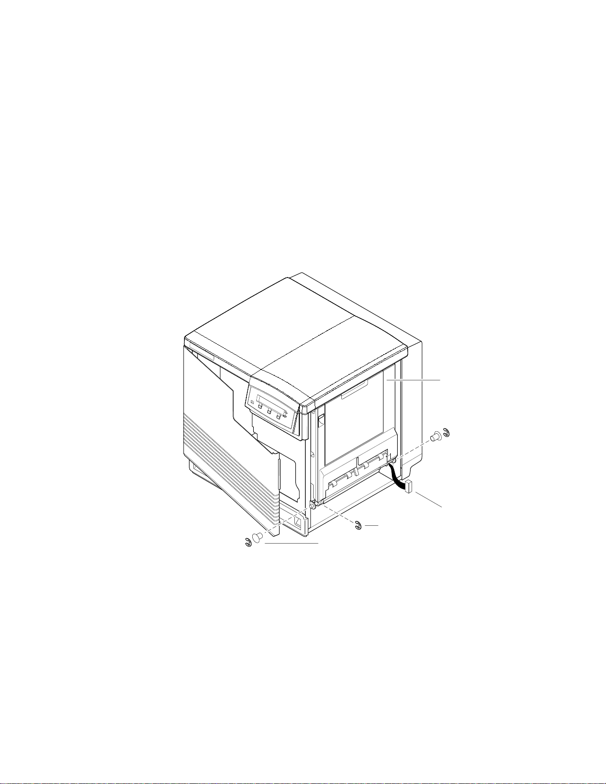
FRU Disassembly/Assembly
1.
2.
3.
4.
8
Cartridge selector/eject unit (right door)
Remove the right-side covers as explained in the earlier topic, “Right
side covers (front, rear and lower)” on page 8-5.
Disconnect the cartridge selector/eject unit’s wiring harness.
Remove the E-ring and bushing from each end of the cartridge
selector/eject unit. Remove the third E-ring from the cartridge
selector/eject unit’s shaft.
Unlatch the cartridge selector/eject unit and lower it half-way down
to relieve spring pressure. Remove the shaft and then remove the
cartridge selector/eject unit.
Remove E-ring
Remove E-ring and
bushing from each
end of the cartridge
selector/eject
unit
Figure 8-4 Removing the cartridge selector/eject unit
Cartridge selector/
eject unit
(right door)
Disconnect
wiring harness
9013-30
8-8
Phaser 540 Color Printer
Page 77
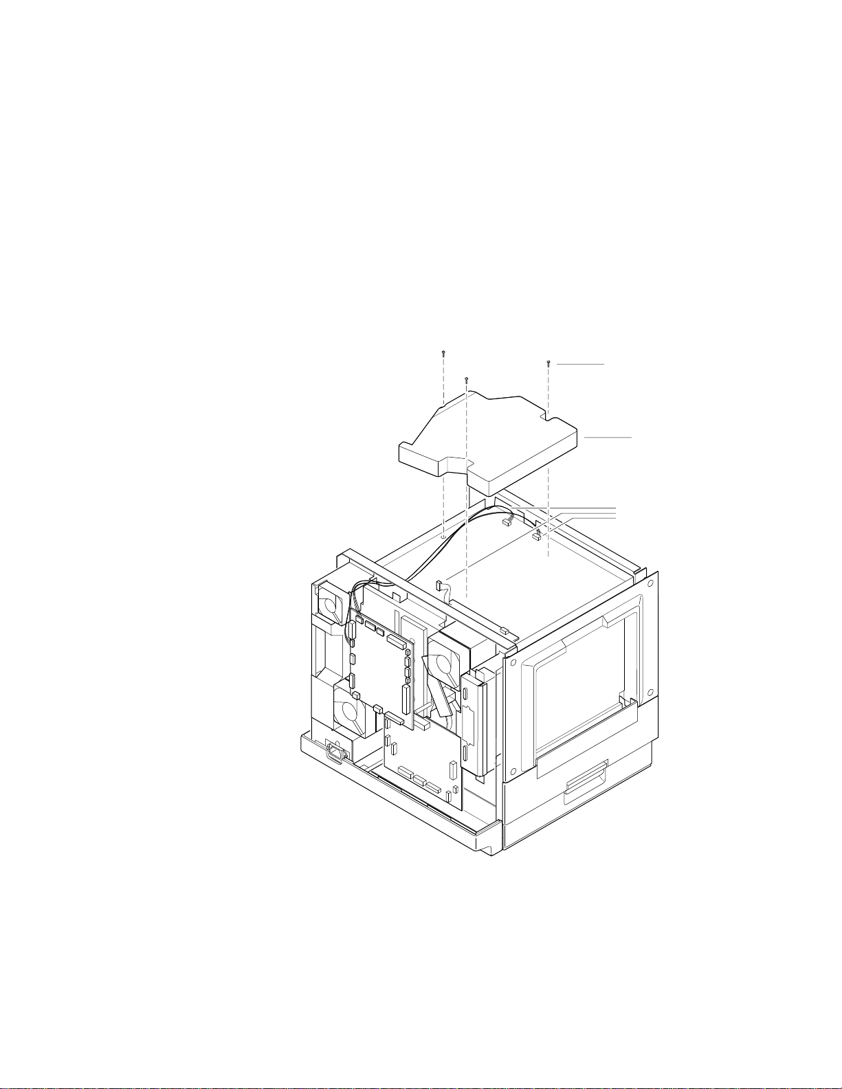
1.
2.
3.
Laser scanner
Note
FRU Disassembly/Assembly
Remove the top cover as explained in the earlier topic, “Top cover” on
page 8-2.
Disconnect the three wiring harnesses connected to the laser scanner.
Remove the three screws securing the laser scanner in place. Lift and
remove the laser scanner.
Cover the laser window slot leading to the imaging unit to protect the
photoconductive belt from room light.
Remove three
screws
Laser scanner
8
Figure 8-5 Removing the laser scanner
Disconnect wiring
harnesses
9013-31
Service Manual
8-9
Page 78
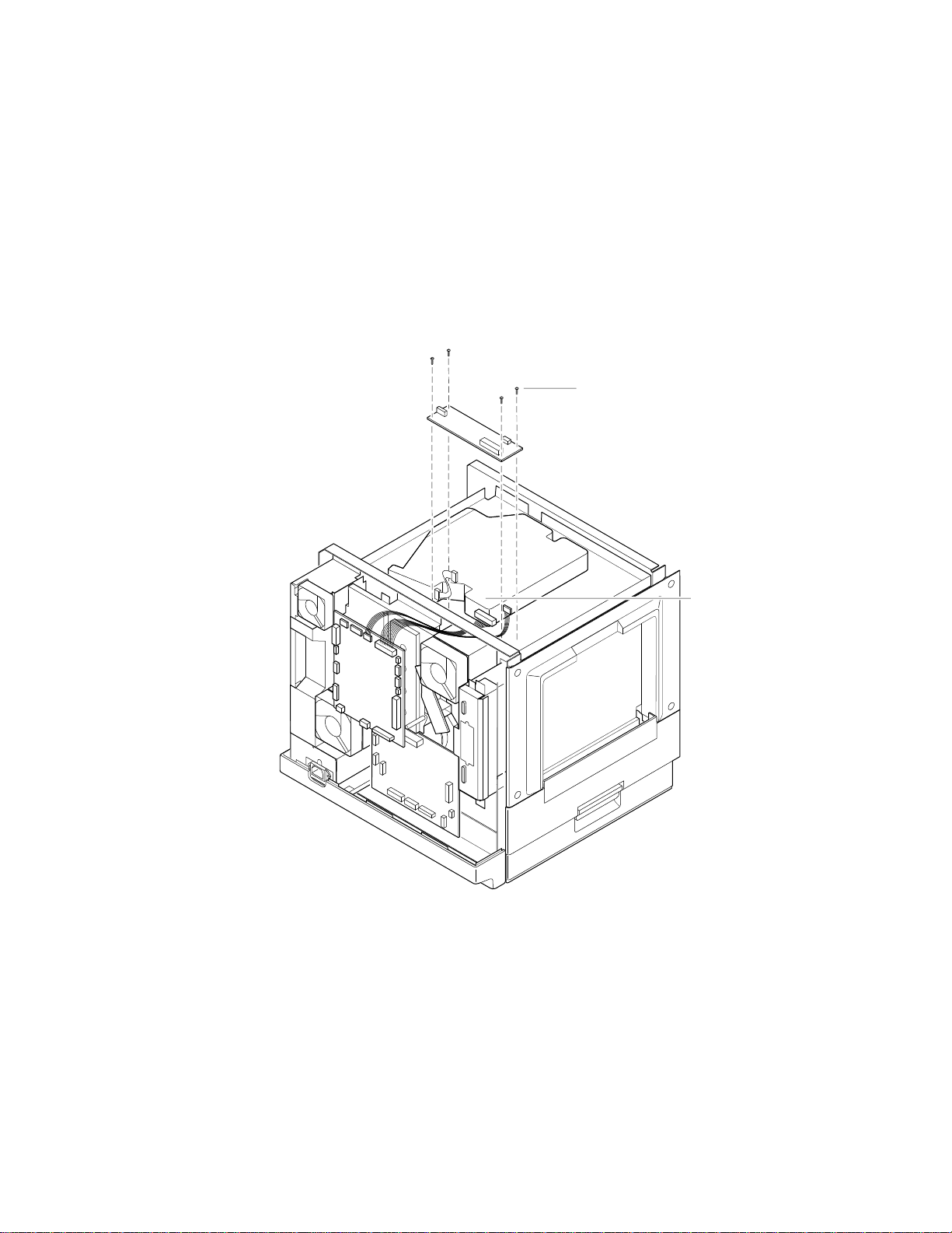
FRU Disassembly/Assembly
1.
2.
3.
8
Laser modulation board
Remove the top cover as explained in the earlier topic, “Top cover” on
page 8-2.
Disconnect the five wiring harnesses connected to the laser
modulation board.
Remove the four screws securing the laser modulation board in place.
Lift and remove the laser modulation board.
Remove the
four screws
Figure 8-6 Removing the laser modulation board
Disconnect the five
wiring harnesses
9013-32
8-10
Phaser 540 Color Printer
Page 79

1.
2.
Power supply
FRU Disassembly/Assembly
Remove the upper and lower rear covers and the rear right side cover
as explained in the earlier topic, “The printer cabinet” on page 8-2.
Disconnect the wiring harnesses connected to the power supply.
3.
Remove the four screws securing the power supply in place. Lift and
remove the power supply.
Caution
Reassembly Note: The bottom of the power supply features two
slots that engage tabs in the printer frame for reassembly. At the
rear base of the power supply, be sure to route the AC wiring
harness through the top of the grommet and out the bottom before
engaging the power supply’s assembly slots to the frame tabs.
Failure to properly route the AC wiring harness can pinch the
wiring and short AC power to the printer frame.
8
Fuser installed switch
1.
Remove the upper and lower rear covers as explained in the earlier
topic, “The printer cabinet” on page 8-2.
2.
Remove the power supply as explained in the previous procedure.
3.
Locate the fuser-installed switch located on the underside of the
printer’s fuser fan housing. Disconnect the switch’s wiring harness.
4.
Remove the screw securing the switch to the fan housing. Remove the
switch.
Service Manual
8-11
Page 80
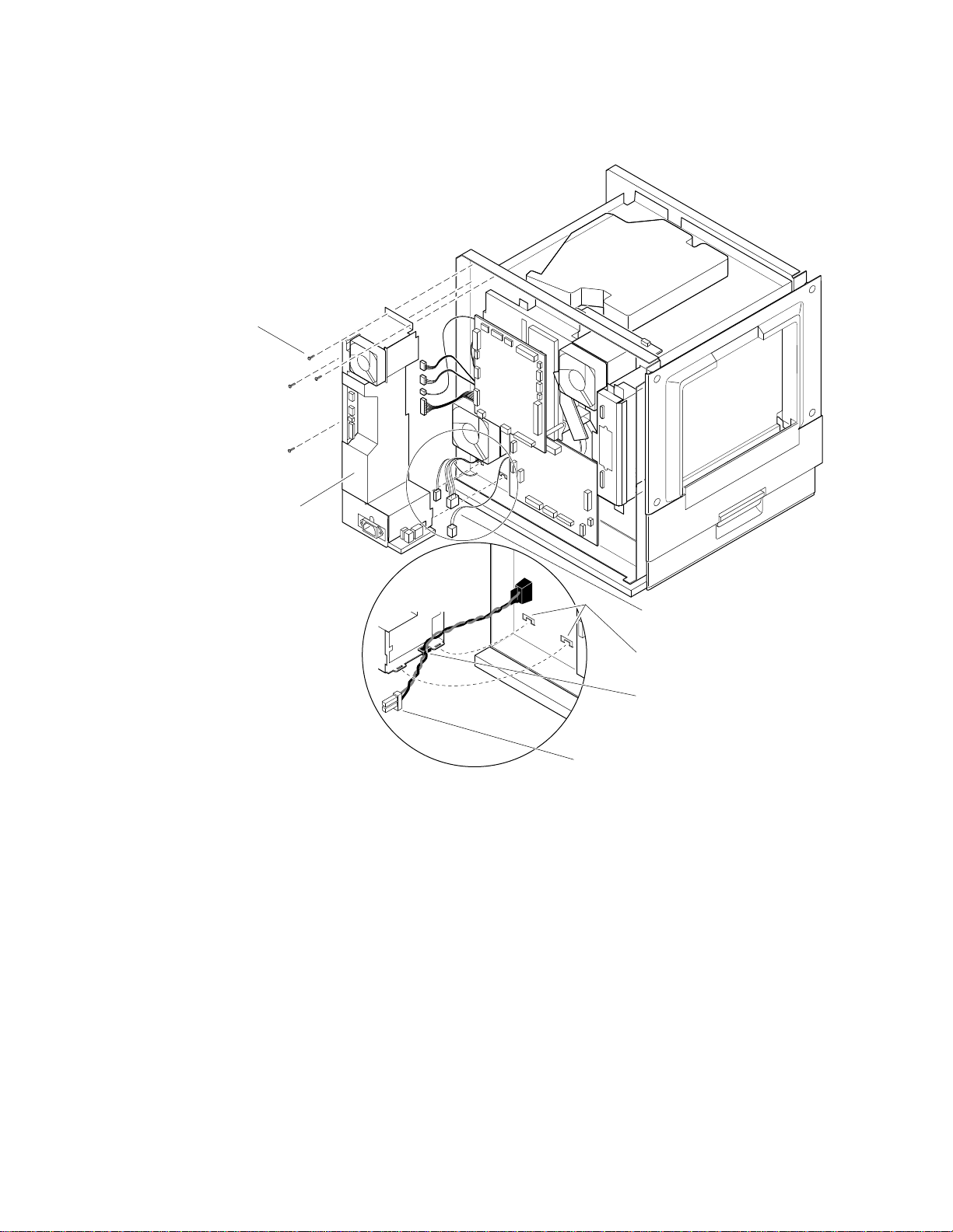
8
FRU Disassembly/Assembly
Remove the
four screws
Power
supply
Power supply
frame tabs
For reassembly:
Route AC wiring
harness through
top of grommet
AC wiring harness
Figure 8-7 Removing the power supply and the fuser installed switch
Disconnect the
wiring harnesses
9013-33
8-12
Phaser 540 Color Printer
Page 81
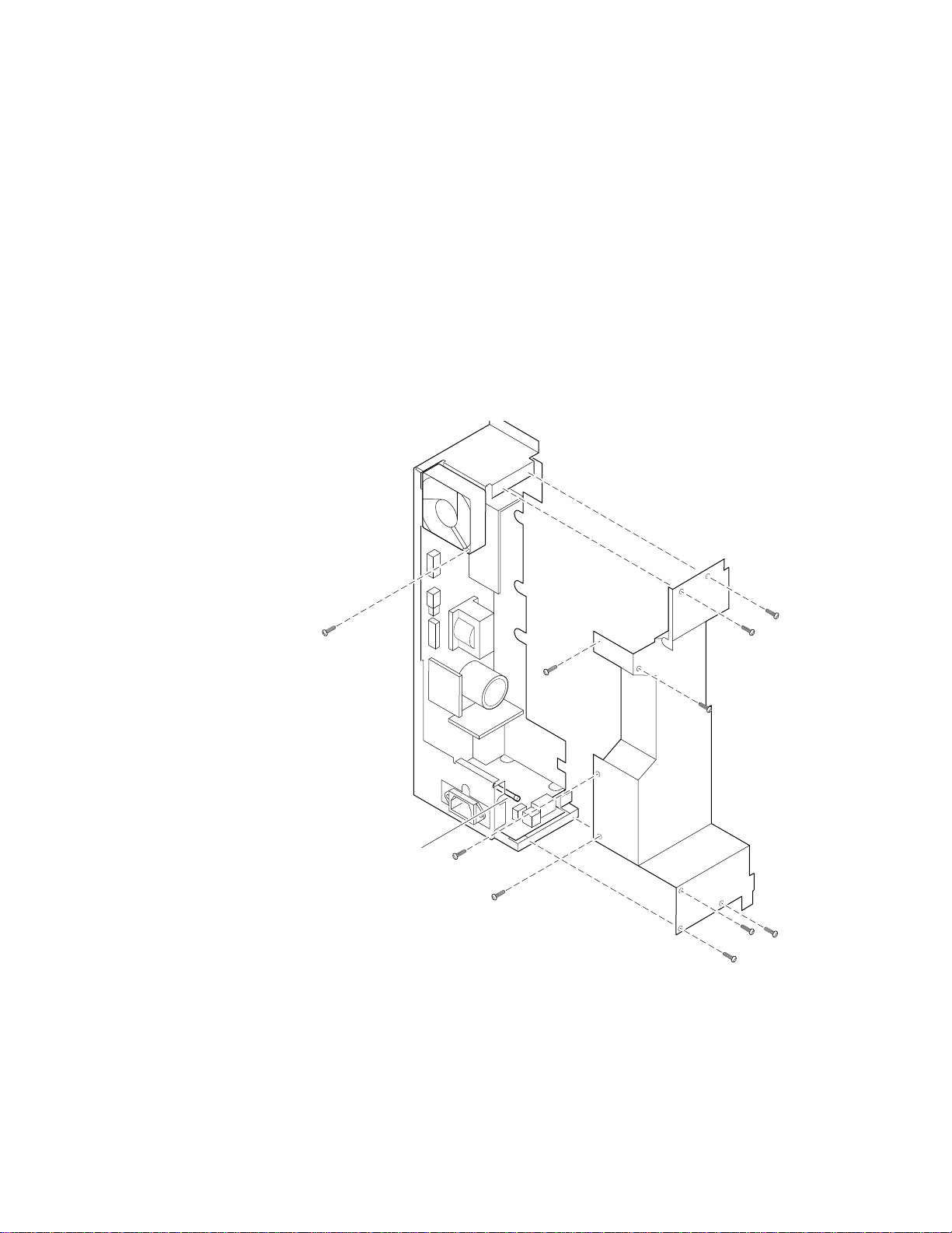
Power supply fuse
FRU Disassembly/Assembly
8
Caution
1.
2.
3.
To avoid damaging the printer, only replace the power supply fuse
with a fuse of the same type and rating.
Remove the power supply as explained in the previous procedure,
“Power supply” on page 8-11.
Remove the power supply’s cover. It is secured in place with
10 screws (one of the screws secures the power supply fan).
Locate the fuse near the bottom of the power supply by the power
cord receptacle.
Fuse
Figure 8-8 Replacing the power supply fuse
9013-34
Service Manual
8-13
Page 82

8
FRU Disassembly/Assembly
Printer rear assemblies
Note
Engine control board
1.
2.
3.
4.
Engine driver board
1.
If you are removing the engine control board or the engine driver
board to access an assembly underneath, it is appropriate to
disconnect the board’s wiring harnesses and then remove the board
and its mounting bracket as an assembly.
Remove the upper rear cover as explained in the earlier procedure,
“Upper rear cover” on page 8-2.
Disconnect the wiring harnesses leading to the engine control board.
Remove the four screws securing the board in place. Remove the
engine control board by pulling it straight out, unplugging it from the
engine driver board.
To remove the engine control board bracket, remove the four screws
securing the bracket in place.
Remove the upper rear cover as explained in the earlier procedure,
“Upper rear cover” on page 8-2.
2.
Remove the engine control board and bracket as explained in the
previous procedure.
3.
Disconnect the wiring harnesses leading to the engine driver board.
4.
Remove the five screws securing the board in place. Remove the
engine driver board.
5.
To remove the engine driver board bracket, remove the four screws
securing the bracket in place.
8-14
Phaser 540 Color Printer
Page 83
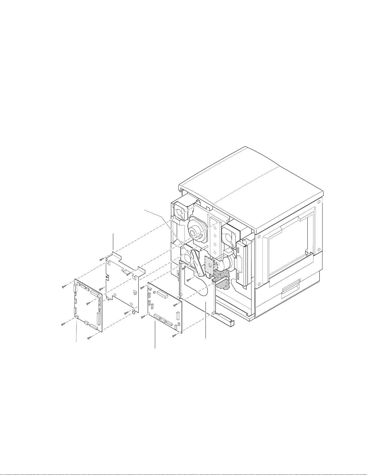
Charger sensor board
1.
2.
3.
4.
FRU Disassembly/Assembly
Remove the upper rear cover as explained in the earlier procedure,
“Upper rear cover” on page 8-2.
Remove the engine control board as explained in the previous
procedure, “Engine control board” on page 8-14.
Disconnect the wiring harnesses leading to the charger sensor board.
Remove the two screws securing the board in place. Remove the
charger sensor board.
8
Charger sensor
board
Engine control
board bracket
Engine control
board
Engine driver
board
Engine driver
board bracket
Figure 8-9 Removing the engine control, engine driver and charger sensor boards
9013-35
Service Manual
8-15
Page 84

8
FRU Disassembly/Assembly
Main motor
Paper feed motor
1.
Remove the upper and lower rear covers and the left side cover as
explained in the earlier procedure, “The printer cabinet” on page 8-2.
2.
Remove the engine control board and bracket as explained in the
previous procedure, “Engine control board” on page 8-14.
3.
Remove the engine driver board and bracket as explained in the
earlier topic, “Engine driver board” on page 8-14.
4.
Disconnect the motor’s wiring harness.
5.
Remove the four screws holding the main motor in place. Remove the
motor.
1.
Remove the upper and lower rear covers and the left side cover as
explained in the earlier procedure, “The printer cabinet” on page 8-2.
Cleaning board
2.
Remove the power supply as explained in the earlier topic, “Power
supply” on page 8-11.
3.
Remove the engine control board and bracket as explained in the
previous procedure, “Engine control board” on page 8-14.
4.
Remove the engine driver board and bracket as explained in the
earlier topic, “Engine driver board” on page 8-14.
5.
Remove the four screws holding the paper feed motor in place.
Remove the motor.
1.
Remove the upper and lower rear covers and the left side cover as
explained in the earlier procedure, “The printer cabinet” on page 8-2.
2.
Remove the engine control board and bracket as explained in the
previous procedure, “Engine control board” on page 8-14.
3.
Remove the engine driver board as explained in the earlier topic,
“Engine driver board” on page 8-14.
8-16
4.
Disconnect the cleaning board’s wiring harness.
5.
Remove the three screws securing the cleaning board in place.
Remove the cleaning board.
6.
If necessary, to remove the cleaning board bracket, remove the two
screws securing the bracket in place.
Phaser 540 Color Printer
Page 85
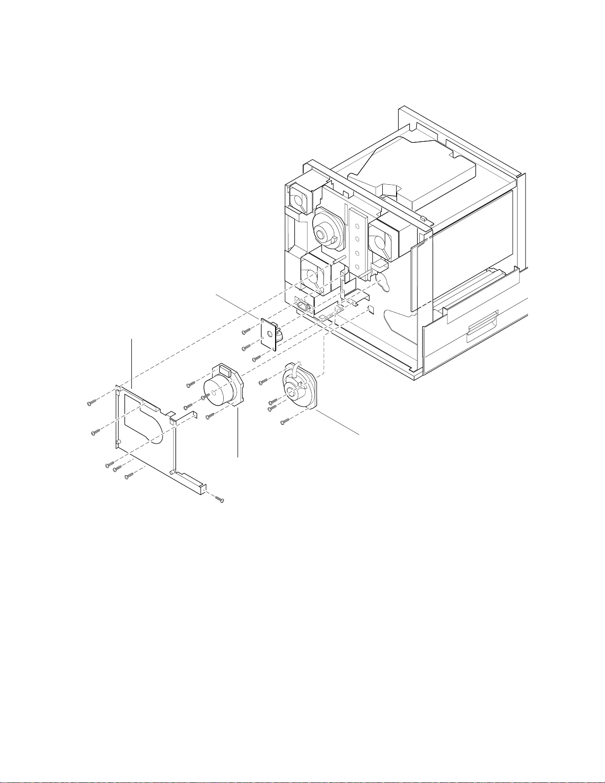
Cleaning board
FRU Disassembly/Assembly
8
Engine driver
board bracket
Paper feed motor
Main motor
Figure 8-10 Removing the main motor, paper-feed motor and cleaning board
9013-36
Service Manual
8-17
Page 86

8
FRU Disassembly/Assembly
Toner cartridge drive unit
1.
Remove the upper and lower rear covers and the left side cover as
explained in the earlier procedure, “The printer cabinet” on page 8-2.
2.
Remove the power supply as explained in the earlier topic, “Power
supply” on page 8-11.
3.
Remove the engine control board and bracket as explained in the
previous procedure, “Engine control board” on page 8-14.
4.
Remove the engine driver board and bracket as explained in the
earlier topic, “Engine driver board” on page 8-14.
5.
Remove the front door/right side door interlock switch.
6.
Remove the cleaning board and the cleaning board bracket as
explained in the previous procedure, “Cleaning board” on page 8-16.
7.
Remove the six screws securing the toner cartridge drive unit to the
printer. Remove the drive unit.
Home position sensor assembly and the left door opened switch
1.
Remove the upper and lower rear covers and left side cover as
explained in the earlier procedure, “The printer cabinet” on page 8-2.
2.
Remove the engine control board and bracket as explained in the
previous procedure, “Engine control board” on page 8-14.
3.
Remove the engine driver board and bracket as explained in the
earlier topic, “Engine driver board” on page 8-14.
4.
Accumulator belt home-position sensor assembly. Remove the two
screws securing the home position sensor assembly in place.
5.
Left door opened switch. Open the left door. Squeeze the interlock
switch’s cover to release it. Move it out of the way.
6.
Disconnect the wiring harness leading to the interlock switch.
7.
Remove the two screws securing the interlock switch in place.
Remove the switch.
8-18
Phaser 540 Color Printer
Page 87
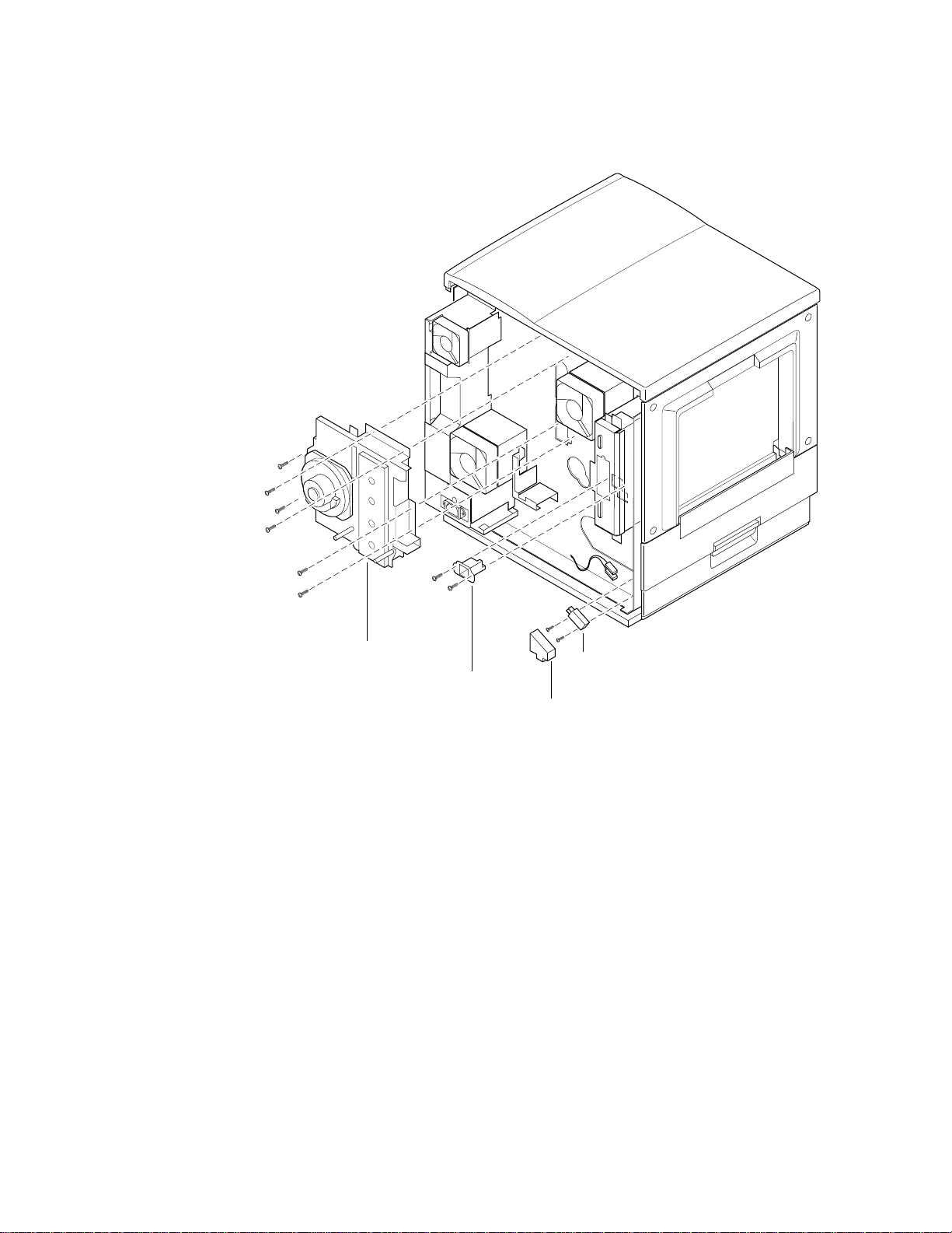
FRU Disassembly/Assembly
8
Toner cartridge
drive unit
Home position
sensor
Left door-opened
interlock switch
Interlock
switch cover
Figure 8-11 Removing the toner cartridge drive unit, home position sensor and the left door interlock switch
9013-37
Service Manual
8-19
Page 88
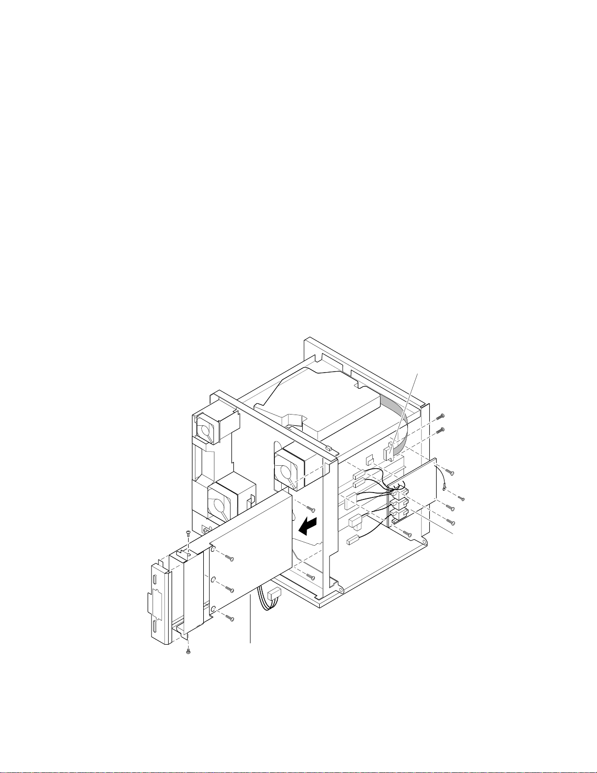
8
FRU Disassembly/Assembly
High-voltage board
1.
Remove the upper rear cover and the left side cover as explained in
the earlier topic, “The printer cabinet” on page 8-2.
2.
Remove the image processor board as explained in the later topic,
“Image processor board” on page 8-23.
3.
Remove the eight screws securing the card cage in place.
4.
Slide the card cage out of the printer far enough to access the wiring
harness at the end of the card cage. Remove the two screws securing
the wiring harness to the card cage. Remove the card cage.
5.
Disconnect the wiring harness leading to the high-voltage board.
Disconnect the high-voltage wires leading from the high-voltage
board to the print engine assemblies.
6.
Remove the four screws and the ground wire securing the
high-voltage board to the printer. Remove the board.
Card cage
Wiring harness
High-voltage
board
9013-38
8-20
Figure 8-12 Removing the high-voltage board
Phaser 540 Color Printer
Page 89

Pre-exposure lamp
1.
Turn off the printer. Remove the imaging unit.
2.
Remove the screw securing the pre-exposure lamp in place.
3.
Disconnect the pre-exposure lamp’s wiring harness. Remove the
lamp.
Pre-transfer lamp
1.
Turn off the printer. Remove the imaging unit.
2.
Remove the E-ring securing the front end of the cleaning cam roller.
Move the front end of the roller out of the way.
3.
Remove the screw securing the pre-transfer lamp in place.
4.
Disconnect the pre-transfer lamp’s wiring harness. Remove the lamp.
FRU Disassembly/Assembly
8
Toner auto-density sensor
1.
Turn off the printer. Remove the imaging unit.
2.
Remove the two screws securing the auto-density sensor in place.
3.
Disconnect the sensors’s wiring harness. Remove the auto-density
sensor.
Service Manual
8-21
Page 90
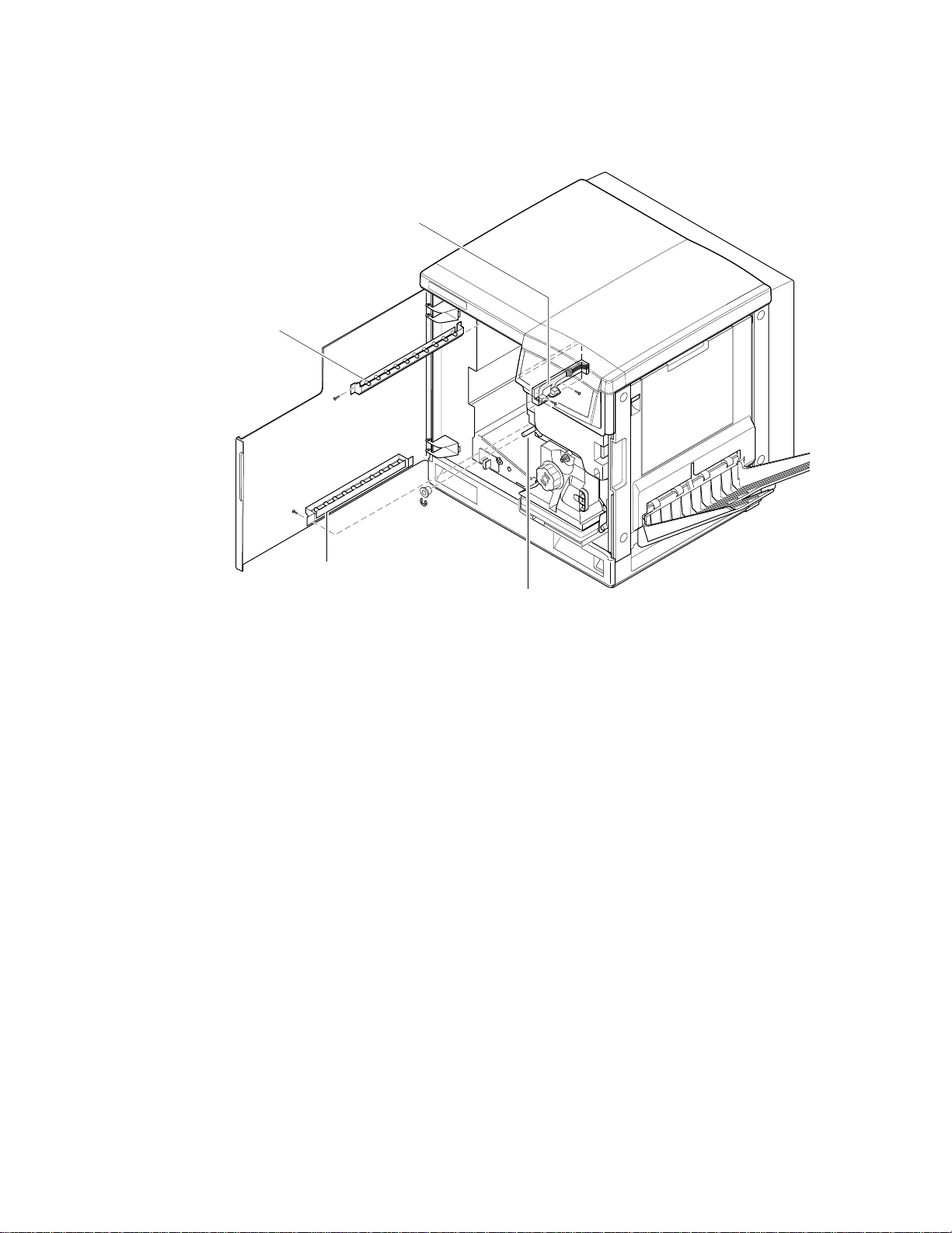
8
9013-39
Toner auto-density
sensor
Pre-transfer
lamp
Pre-exposure
lamp
Cleaning cam
roller
FRU Disassembly/Assembly
Figure 8-13 Removing the pre-exposure lamp, pre-transfer lamp and toner auto-density sensor
8-22
Phaser 540 Color Printer
Page 91
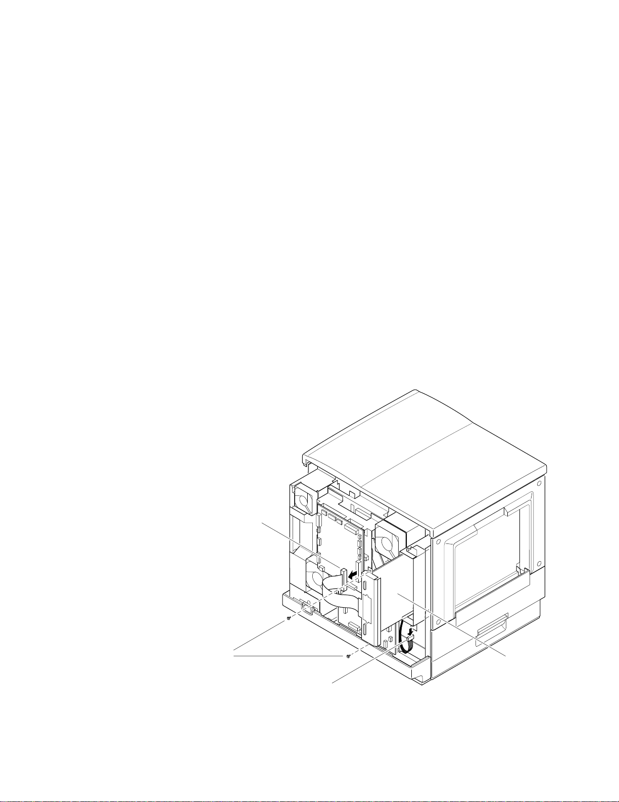
Image processor board
1.
Power down the printer. Disconnect all host interface cables.
2.
Remove the upper rear cover as explained in the earlier topic, “Upper
rear cover” on page 8-2.
3.
Disconnect the image processor’s data wiring harness from the engine
control board. Disconnect the power wiring harness from the
underside of the image processor board.
4.
Remove the two screws securing the board's rear panel to the printer.
5.
Grasp the rear panel and slide the board out of the printer card cage.
Reverse these steps to reinstall the board.
If you are replacing the image processor board, exchange the NVRAM IC and
the Ethernet address ROMs between the two boards. The 8-pin NVRAM chip
contains important customer-created parameters. The printer may not operate
correctly without the NVRAM IC being swapped. The socketed NVRAM IC is
located near the RAM SIMMs. The 16-pin Ethernet address ROM is located
above the network card connector.
FRU Disassembly/Assembly
8
Disconnect data
wiring harness
Remove
screws
Disconnect power
wiring harness
Figure 8-14 Removing the image processor board
Service Manual
Image
processor
board
9013-41
8-23
Page 92

8
FRU Disassembly/Assembly
Installing RAM SIMMs
1.
Turn off the printer. Do not unplug the printer; this preserves a
ground path to dissipate static charges.
2.
Open the manual feed tray on the left side of the printer.
3.
Loosen the two thumbscrews securing the RAM access cover.
4.
Remove the EMI shield.
5.
Insert a memory module in connector P81 SIMM ONE (or in
P82 SIMM TWO if P81 SIMM ONE is already filled) (a) and tilt the
module down until it locks in place (b).
6.
Repeat Step 4 to install additional memory modules. Install memory
modules in the order P81 SIMM ONE and then P82 SIMM TWO.
When properly inserted, a tab on each end of the connector slips into a
hole on each end of the RAM SIMM. Also, a pawl on each end of the
connector latches around each end of the RAM SIMM to lock it in
place.
7.
Reinstall the EMI shield and the SIMM access cover. Close the manual
feed tray.
8.
Print a startup page to check its listing of the printer's memory and
options.
8-24
Phaser 540 Color Printer
Page 93
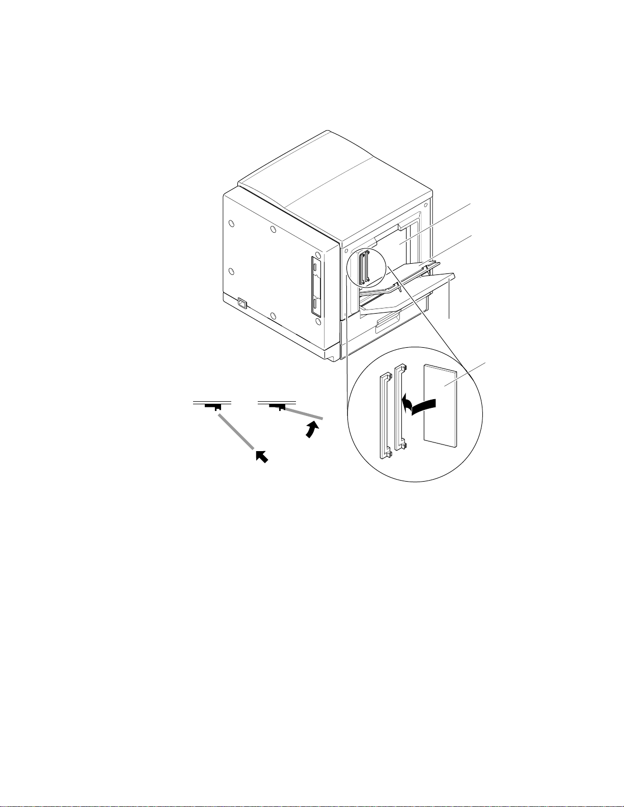
FRU Disassembly/Assembly
8
Note
Ensure that the SIMM's RAM ICs are 70 nsec (-70) components.
Slower RAM ICs won't work with the image processor board.
Image processor
board
RAM SIMM
access cover
Manual feed tray
RAM SIMM
ab
Figure 8-15 Installing RAM SIMMs
SIMM 1
SIMM 2
9013-42
Service Manual
8-25
Page 94
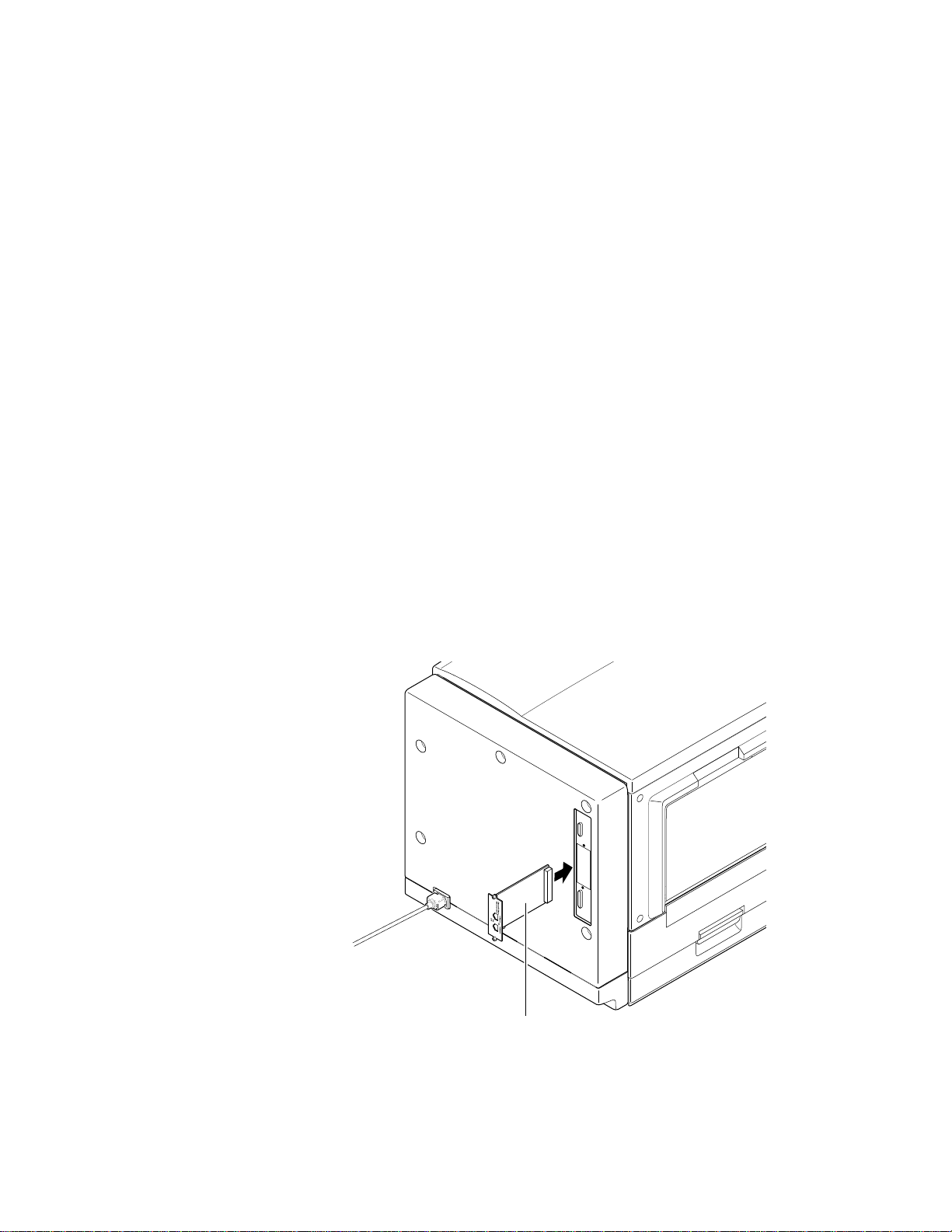
8
FRU Disassembly/Assembly
Installing a network card
Note
1.
2.
3.
4.
5.
EtherTalk and LocalTalk protocols require you to attach the Ethernet
cable to the printer with the printer powered off. After connection,
turn on the printer. During the printer's boot-up process, the
printer's network node address is resolved with the network.
Power down the printer. Do not unplug the printer; this preserves a
ground path to dissipate static charges.
Remove the network card cover plate from the rear panel of the
printer.
Slide the network card into the card slot and firmly push it in place.
Secure it in place with two screws.
Token Ring network card.
printer’s Token Ring network card is set for the speed of the token
ring network. Not installed set the card for 16 Mbps (the most
common configuration); installed set the card for 4 Mbps.
Connect the appropriate host interface cable to the network card.
Turn on the printer and print the startup page. It lists the installed
memory and options.
Ensure the transmission speed jumper on the
8-26
Network card
9013-43
Figure 8-16 Installing a network card in the printer
Phaser 540 Color Printer
Page 95

Enabling TCP/IP with the authorization code
Newer printers with PhaserShare Version 2.0 or higher firmware installed on the
network card already have TCP/IP authorized; older printers do not. Print and
refer to the printer’s configuration page to determine the version of PhaserShare
operating on the network card. Phaser Share network card upgrades, 4676UP1
(for an Ethernet card) or 4676UP4 (for a Token Ring card), are available to
upgrade network cards to Version 2.0 PhaserShare.
When the Ethernet card is installed, the EtherTalk and Novell protocols are
immediately active. The Ethernet card’s TCP/IP protocol must be activated (for
older printers) by a downloadable authorization code, sometimes referred to as
its software key. The authorization code is printed on a certificate included with
the printer (if the option was factory-installed) or with the field upgrade kit. The
Phaser Share User Manual explains how to activate the authorization code and
download it to the printer. Downloading the code depends on the available
computers and cables as explained in the network user manual.
Each Ethernet card requires a unique authorization code to activate its TCP/IP
protocol. The authorization code is based on the printer’s Ethernet address and
is generated by a special computer program. The computer program is held by
the staff of the Customer Support Hotline. A staff member of the Customer
Support Hotline can generate an authorization code for an Ethernet-capable
printer anytime once purchase of the TCP/IP option has been confirmed, even
long after the Ethernet card was installed.
FRU Disassembly/Assembly
8
Service Manual
8-27
Page 96
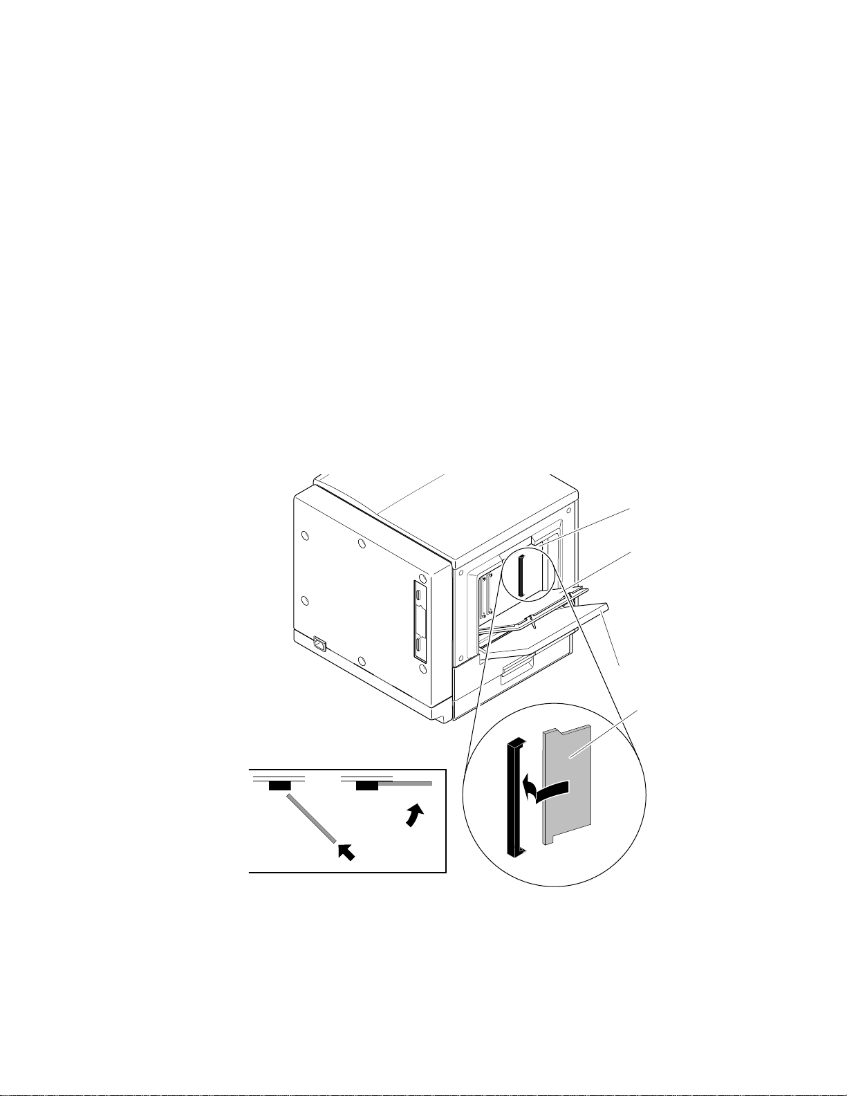
8
1
FRU Disassembly/Assembly
Replacing the code ROM SIMM
1.
Turn off the printer. Do not unplug the printer; this preserves a
ground path to dissipate static charges.
2.
Open the manual feed tray on the left side of the printer. Loosen the
two thumbscrews securing the RAM access cover.
3.
Remove the EMI shield.
4.
Remove the PostScript ROM SIMM by spreading the pawls securing it
in its connector.
5.
Install the new PostScript ROM SIMM. When properly inserted, a tab
on each end of the connector slips into a hole on each end of the ROM
SIMM. Also, a pawl on each end of the connector latches around each
end of the ROM SIMM to lock it in place.
6.
Reinstall the EMI shield and the SIMM access cover. Close the manual
feed tray.
ab
Image processor
board
RAM SIMM
access cover
Manual feed tray
Code ROM SIMM
9013-6
8-28
Figure 8-17 Installing the code ROM SIMM
7.
Turn on the printer and print a startup page to check the printer’s
performance.
Phaser 540 Color Printer
Page 97

Chapter
7
Cleaning and
Maintenance
Service preventive maintenance procedure
Whenever you check, service, or repair a printer, you should perform the
following procedures. Cleaning the printer, as outlined in the following steps,
assures proper operation of the printer and reduces the probability of having to
service the printer in the future.
The frequency of use and the type of paper a customer prints on will, in large
part, determine how critical cleaning the machine is. Users of ordinary Bond
paper (copier paper) should have very few problems since this paper is smooth
and relatively dust-free. You should thoroughly inspect and clean these printers.
Ask each printer customer about the type of paper he or she uses so that you can
be sure to clean the parts of the printer that particular paper may affect. If a
customer is printing on the more unusual or dustier papers, then you should
pay particular attention to these printer parts:
■
The pick roller
The feed rollers
■
■
The cabinet interior
■
The exit rollers
Recommended tools
vacuum cleaner
■
■
suction bulb (air blower)
cleaning alcohol
■
■
lint-free wipes
cotton swabs
■
■
imaging unit cover
Service Manual
7-1
Page 98

1.
2.
3.
4.
5.
6.
7.
8.
9.
Cleaning and Maintenance
7
Cleaning
Turn off the printer.
Remove the imaging unit and cover it to protect it from the light.
Remove the toner cartridges.
Remove the fuser.
Remove the paper tray.
Slide out the paper feeder.
Clean the pre-transfer corona with its cleaning tool.
Clean the image density sensor with the cotton swab.
Lubrication
Clean the accumulator belt home position sensor with a cotton swab.
10.
Clean all printer rollers with alcohol wipes.
11.
Clean the laser window with puffs of air from the suction bulb.
Alternately, you can vacuum the window clean.
12.
Wipe off the pre-exposure lamp bezel and the pre-transfer lamp bezel
with a lint-free wipe.
13.
Vacuum out the interior of the printer.
■
Molybdenum-based grease
For all metal-to-metal, metal-to-plastic, and plastic-to-plastic gears.
High-temperature, electrically-conductive grease,
■
FLOIL GE-676 by Kanto Kasei, Ltd.
For the plastic gears of the fuser and the end of the transfer roller
shaft.
7-2
Phaser 540 Color Printer
Page 99

Chapter
6
Troubleshooting
This chapter discusses troubleshooting the printer. Troubleshooting is discussed
with two approaches:
■
A step-by-step verification procedure that systematically confirms that
particular components of the printer are properly functioning until a
problem is found.
■
A symptom/cause scheme that lists particular printer failures and
error codes and their possible causes.
System power-up sequence
The following lists the chain of events that occur when you turn on the printer.
You can follow this list as one means of determining if the printer is operating
correctly.
When the power switch is turned on, these events occur:
■
The engine control board checks its RAM.
■
All the engine fans are turned on to ensure they work properly.
■
The fuser heater (a halogen lamp) is activated to heat up the heated
roller.
The position of each toner cartridge is checked to ensure they are in
■
their parked positions.
■
A print engine checks to see that the imaging unit, the paper feeder
and the pre-transfer charger are installed.
■
The engine motors are rotated to ensure that their rotation sensors are
detected.
The transparency film sensor and the image density sensors are
■
“tuned” for the amount of infrared light they each emit.
A check is made to determine if any paper is jammed in the printer.
■
■
The print engine checks the level of toner in each toner cartridge.
Service Manual
6-1
Page 100

1.
2.
3.
4.
Troubleshooting
6
After the fuser reaches its idle temperature, a color correction cycle is
■
performed.
The printer is placed on line in its READY state.
■
The print engine is initialized. If the startup page feature has not been disabled
and no error occurred with the printer, the printer prints a startup page.
Print engine troubleshooting
This topic is a step-by-step procedure for systematically verifying particular
aspects of the printer's operation. Following this procedure should lead to the
cause of a printer's failure.
Testing the print engine
If the printer does not power up, or does not initialize, or the printer
initializes but the motors do not run properly, go to the later topic,
“Verifying power supply operation” on page 6-3.
Note
If the printer prints a gray fill, then the printer's print engine is working
correctly. Proceed with the next topic, “Verifying printer operation by using its
self-test print” on page 6-3.
If the image processor does not power up or is disconnected from its
power source, then the print engine will not power up.
Observe that the Ready message is displayed on the front panel. If it
is not, go to the later topic “Verifying power supply operation” on
page 6-3.
Verify that the image processor’s health LED is flashing. If it is not, go
to the topic, “Printer self-diagnostics” on page 9-6. The health LED is
viewable through the grill behind the manual feed tray (when the tray
is lowered).
Press the test button on the rear of the printer (in the center of the rear
cabinet panel). The print engine responds by making a gray fill test
print.
6-2
If the printer does not make the gray fill print, then a problem exists with the
printer. If the printer does not print a test pattern, then a problem exists with the
print engine. Proceed with the topic, “Verifying power supply operation” on
page 6-3.
Phaser 540 Color Printer
 Loading...