


Model A-P3
(Machine Code: G065)
SERVICE MANUAL
November 6th, 2001
Subject to change

!
IMPORTANT SAFETY NOTICES
PREVENTION OF PHYSICAL INJURY
1. Before disassembling or assembling parts of the printer and peripherals,
make sure that the printer power cord is unplugged.
2. The wall outlet should be near the printer and easily accessible.
3. Note that some components of the printer and the paper tray unit are
supplied with electrical voltage even if the main power switch is turned off.
4. If any adjustment or operation check has to be made with exterior covers off
or open while the main switch is turned on, keep hands away from electrified
or mechanically driven components.
5. The inside and the metal parts of the fusing unit become extremely hot while
the printer is operating. Be careful to avoid touching those components with
your bare hands.
HEALTH SAFETY CONDITIONS
Toner and developer are non-toxic, but if you get either of them in your eyes by
accident, it may cause temporary eye discomfort. Try to remove with eye drops
or flush with water as first aid. If unsuccessful, get medical attention.
OBSERVANCE OF ELECTRICAL SAFETY STANDARDS
1. The printer and its peripherals must be installed and maintained by a
customer service representative who has completed the training course on
those models.
2. The NVRAM on the system control board has a lithium battery which can
explode if replaced incorrectly. Replace the NVRAM only with an identical
one. The manufacturer recommends replacing the entire NVRAM. Do not
recharge or burn this battery. Used NVRAM must be handled in accordance
with local regulations.
SAFETY AND ECOLOGICAL NOTES FOR DISPOSAL
1. Do not incinerate toner bottles or used toner. Toner dust may ignite suddenly
when exposed to an open flame.
2. Dispose of used toner, developer, and organic photoconductors in
accordance with local regulations. (These are non-toxic supplies.)
3. Dispose of replaced parts in accordance with local regulations.
4. When keeping used lithium batteries in or der to dispose of them later, do not
put more than 100 batteries per sealed box. Storing larger numbers or not
sealing them apart may lead to chemical reactions and heat build-up.
LASER SAFETY
The Center for Devices and Radiological Health (CDRH) prohibits the repair of
laser-based optical units in the field. The optical housing unit can only be repaired
in a factory or at a location with the requisite equipment. The laser subsystem is
replaceable in the field by a qualified Customer Engineer. The laser chassis is not
repairable in the field. Customer engineers are therefore directed to return all
chassis and laser subsystems to the factory or service depot when replacement of
the optical subsystem is required.
!
WARNING
Use of controls, or adjustment, or performance of procedures other than
those specified in this manual may result in hazardous radiation exposure.
!
WARNING
WARNING: Turn off the main switch before atte mpting any of the
procedures in the Laser Unit section. Laser beams can seriously damage
your eyes.
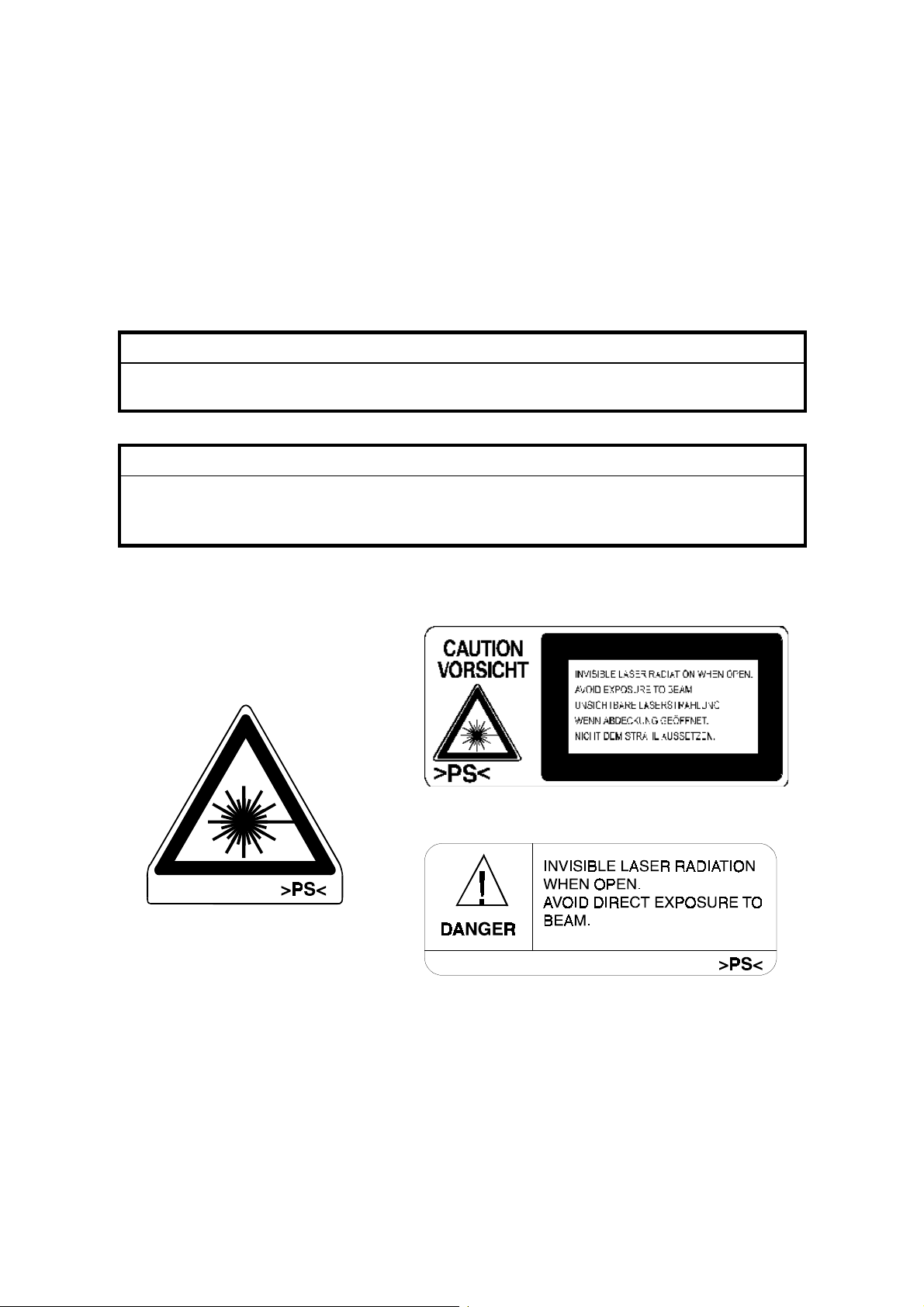
Caution Labels
LASER-3.WMF
G065RLW.WMF
LASER-1.WMF
Lithium Batteries (Memory Back-up)
!
CAUTION
The danger of explosion exists if a battery of this type is incorrectly
replaced. Replace only with the same or an equivalent type recommended
by the manufacturer. Discard used batteries in accordance with the
manufacturer’s instructions.
Warning Concerning Copyright
Many documents are copyrighted. Such documents may not be reproduced by
copying or in any other form without the express permission of the copyright holder.
Conventions in this Manual
This manual uses several symbols and some simple abbreviations.
Symbol What it means
☛
!
"
#
$
%
HP Home Position
T/S Transfer/Separation
Refer to section number
See Core Tech Manual for details
Screw
Connector
E-ring
C-ring
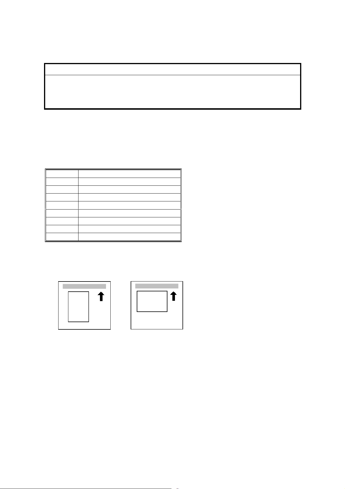
The following notations are used in text to describe the direction of paper feed:
lengthwise and sideways. The annotations “SEF” and “LEF” denote “Short Edge
Feed” and “Long Edge Feed’. (The arrows indicate the direction of paper feed.)
Lengthwise (SEF) Sideways (LEF)

TABLE OF CONTENTS
1. INSTALLA TION .......................................................................... 1-1
1.1 INSTALLATION REQUIREMENTS...........................................................1-1
1.1.1 ENVIRONMENT...............................................................................1-1
1.1.2 MACHINE LEVEL.............................................................................1-1
1.1.3 MACHINE SPACE REQUIREMENTS.............................................. 1-2
1.1.4 POWER REQUIREMENTS..............................................................1-3
1.2 MACHINE INSTALLATION .......................................................................1-3
1.3 OPTIONAL UNIT INSTALLATION.............................................................1-3
1.4 SYMBOLS USED IN TEXT .......................................................................1-3
1.5 LCT INSTALLATION (A683)......................................................................1-4
1.5.1 ACCESSORY CHECK......................................................................1-4
1.5.2 INSTALLATION PROCEDURE........................................................1-5
1.6 BRIDGE UNIT INSTALLATION (B397).....................................................1-7
1.6.1 ACCESSORY CHECK......................................................................1-7
1.6.2 INSTALLATION PROCEDURE........................................................1-8
1.7 1000-SHEET FINISHER INSTALLATION (A681)....................................1-10
1.7.1 ACCESSORY CHECK....................................................................1-10
1.7.2 INSTALLATION PROCEDURE......................................................1-11
1.8 3000-SHEET FINISHER INSTALLATION (A697)....................................1-14
1.8.1 ACCESSORY CHECK....................................................................1-14
1.8.2 INSTALLATION PROCEDURE......................................................1-15
1.9 PUNCH UNIT INSTALLATION (A812)....................................................1-19
1.9.1 ACCESSORY CHECK....................................................................1-19
1.9.2 INSTALLATION PROCEDURE......................................................1-20
1.10 MAILBOX INSTALLATION (G909)........................................................1-23
1.10.1 ACCESSORY CHECK..................................................................1-23
1.10.2 REQUIREMENT OPTIONS FOR MAIN MACHINE......................1-23
1.10.3 INSTALLATION PROCEDURE....................................................1-24
1.11 BRIDGE UNIT FOR MAILBOX INSTALLATION (G912) .......................1-27
1.11.1 ACCESSORY CHECK..................................................................1-27
1.11.2 INSTALLATION PROCEDURE....................................................1-28
2. PREVENTIVE MAINTENANCE SCHEDULE.............................. 2-1
2.1 PM TABLES ..............................................................................................2-1
2.1.1 PM TABLES FOR THE PRINTER....................................................2-1
2.1.2 PM TABLES FOR OPTIONS............................................................2-3
3. REPLACEMENT AND ADJUSTMENT........................................ 3-1
3.1 GENERAL CAUTIONS..............................................................................3-1
3.1.1 LASER UNIT ....................................................................................3-1
3.1.2 USED TONER..................................................................................3-1
3.2 SPECIAL TOOLS AND LUBRICANTS......................................................3-2
3.2.1 SPECIAL TOOLS.............................................................................3-2
3.2.2 LUBRICANTS...................................................................................3-2
i

3.2.3 SYMBOLS USED IN TEXT...............................................................3-2
3.3 FRONT DOOR ..........................................................................................3-3
3.4 DUPLEX UNIT...........................................................................................3-3
3.5 UPPER RIGHT COVER............................................................................3-4
3.6 BY-PASS TRAY UNIT...............................................................................3-5
3.7 REAR COVERS ........................................................................................3-6
3.7.1 REAR UPPER COVER.....................................................................3-6
3.7.2 REAR LOWER COVER....................................................................3-6
3.8 LEFT COVERS..........................................................................................3-7
3.8.1 LEFT UPPER COVER......................................................................3-7
3.8.2 OPERATION PANEL........................................................................3-8
3.8.3 PAPER OUTPUT TRAY...................................................................3-9
No Bridge Unit Installed........................................................................3-9
Bridge Unit Installed..............................................................................3-9
3.9 LASER UNIT........................................................................................... 3-10
3.9.1 CAUTION DECAL LOCATIONS.....................................................3-10
3.9.2 LASER UNIT ..................................................................................3-11
3.9.3 POLYGON MIRROR MOTOR........................................................3-12
3.9.4 LASER SYNCHRONIZATION DETECTOR....................................3-13
3.9.5 LD UNIT..........................................................................................3-13
Laser Beam Pitch Adjustment.............................................................3-14
3.10 PCDU....................................................................................................3-15
3.10.1 PHOTOCONDCUTOR CLEANING/DEVELOPMENT UNIT.........3-15
3.10.2 DRUM...........................................................................................3-16
3.10.3 PICK-OFF PAWLS.......................................................................3-17
3.10.4 CHARGE ROLLER AND CLEANING ROLLER ............................3-18
3.10.5 DRUM CLEANING BLADE...........................................................3-19
3.10.6 ID SENSOR..................................................................................3-20
3.11 DEVELOPMENT................................................................................... 3-21
3.11.1 DEVELOPMENT UNIT.................................................................3-21
3.11.2 DEVELOPMENT FILTER............................................................. 3-22
3.11.3 DEVELOPMENT ROLLER...........................................................3-23
3.11.4 DEVELOPER................................................................................3-24
3.11.5 TD SENSOR.................................................................................3-26
3.12 TRANSFER UNIT..................................................................................3-27
3.12.1 TRANSFER BELT UNIT...............................................................3-27
3.12.2 TRANSFER BELT........................................................................3-28
3.12.3 CLEANING BLADE/TONER OVERFLOW SENSOR....................3-29
Transfer Belt Cleaning Blade..............................................................3-29
Toner Overflow Sensor.......................................................................3-29
3.13 PAPER FEED........................................................................................3-30
3.13.1 PICK-UP, SEPARATION, AND FEED ROLLERS ........................3-30
3.13.2 LOWER RIGHT COVER...............................................................3-31
3.13.3 RELAY/UPPER PAPER FEED AND LOWER PAPER FEED
CLUTCHES..................................................................................3-32
3.13.4 UPPER PAPER FEED UNIT FOR TRAY 1..................................3-33
3.13.5 LOWER PAPER FEED UNIT FOR TRAY 2.................................3-34
3.13.6 PAPER END/PAPER LIFT/RELAY SENSORS............................3-35
3.13.7 REGISTRATION SENSOR...........................................................3-36
ii

3.13.8 TRAY LIFT MOTOR.....................................................................3-38
3.13.9 FEED/DEVELOPMENT MOTOR..................................................3-39
3.14 FUSING.................................................................................................3-40
3.14.1 FUSING UNIT...............................................................................3-40
3.14.2 FUSING UNIT EXIT GUIDE .........................................................3-41
3.14.3 HOT ROLLER STRIPPERS .........................................................3-41
3.14.4 FUSING LAMPS...........................................................................3-42
Left Side..............................................................................................3-42
Right Side...........................................................................................3-43
3.14.5 THERMISTORS AND THERMOSTATS.......................................3-44
3.14.6 HOT ROLLER/PRESSURE ROLLER...........................................3-45
3.15 BY-PASS TRAY....................................................................................3-47
3.15.1 COVER REPLACEMENT.............................................................3-47
3.15.2 BY-PASS FEED/PICK-UP ROLLER.............................................3-48
3.15.3 BY-PASS SEPARATION ROLLER REPLACEMENT...................3-49
3.15.4 PAPER END SENSOR/PICK-UP SOLENOID..............................3-50
3.15.5 PAPER SIZE SENSOR BOARD REPLACEMENT.......................3-51
3.15.6 BY-PASS TABLE REMOVAL.......................................................3-52
3.15.7 PAPER FEED CLUTCH REPLACEMENT....................................3-53
3.16 DUPLEX UNIT.......................................................................................3-54
3.16.1 DUPLEX COVER REMOVAL.......................................................3-54
3.16.2 DUPLEX ENTRANCE SENSOR REPLACEMENT....................... 3-55
3.16.3 DUPLEX EXIT SENSOR REPLACEMENT ..................................3-56
3.17 DRIVE AREA.........................................................................................3-57
3.17.1 REGISTRATION/TRANSFER BELT CONTACT CLUTCHES......3-57
3.17.2 MAIN MOTOR..............................................................................3-58
3.17.3 FUSING/EXIT MOTOR.................................................................3-59
3.17.4 FUSING/EXIT CLUTCH................................................................3-60
3.17.5 TONER SUPPLY MOTOR............................................................3-61
3.18 PRINTED CIRCUIT BOARDS...............................................................3-62
3.18.1 HIGH VOLTAGE POWER SUPPLY.............................................3-62
3.18.2 I/O BOARD...................................................................................3-63
3.18.3 BICU BOARD...............................................................................3-64
3.18.4 PSU..............................................................................................3-64
3.19 HARD DISK/CONTROLLER BOARD ....................................................3-65
To Format the HDD.............................................................................3-65
3.20 PRINTING ADJUSTMENTS..................................................................3-66
3.21 PARALLELOGRAM IMAGE ADJUSTMENT .........................................3-67
4. TROUBLESHOOTING ................................................................ 4-1
4.1 SERVICE CALL CONDITIONS.................................................................4-1
4.1.1 SUMMARY.......................................................................................4-1
4.1.2 SC CODE DESCRIPTIONS .............................................................4-2
4.2 ELECTRICAL COMPONENT DEFECTS ................................................4-13
4.2.1 SENSORS......................................................................................4-13
4.2.2 SWITCHES.....................................................................................4-14
4.3 BLOWN FUSE CONDITIONS.................................................................4-15
4.4 LEDS.......................................................................................................4-15
iii

BICU...................................................................................................4-15
4.5 TEST POINTS.........................................................................................4-15
Controller Board..................................................................................4-15
5. SERVICE TABLES...................................................................... 5-1
5.1 SERVICE PROGRAM MODE....................................................................5-1
5.1.1 ENTERING AND LEAVING THE SERVICE PROGRAM MODE......5-1
5.2 PRINTER CONTROLLER SERVICE MODE.............................................5-2
5.2.1 CONTROLLER SERVICE MODE MENUS.......................................5-2
5.2.2 BIT SWITCH PROGRAMMING........................................................5-2
5.2.3 PRINTER CONTROLLER BIT SWITCH SETTINGS........................5-3
5.3 PRINTER ENGINE SERVICE MODE........................................................5-4
Leaving the SP Mode.............................................................................5-5
5.3.1 SERVICE PROGRAM MODE TABLES............................................5-6
1. Feed (SP1000-00)..............................................................................5-6
2. Drum (SP2000-00) ...........................................................................5-10
3. Process (SP3000-00).......................................................................5-20
4. HDD (SP4000-00) ............................................................................5-21
5. Mode (SP5000-00)...........................................................................5-21
6. Peripherals (SP6000-00)..................................................................5-25
7. Data Log (SP7000-00)......................................................................5-26
5.3.2 TEST PATTERN PRINTING...........................................................5-29
Test Pattern Table: SP2902-03 Printing Test Patterns.......................5-30
5.3.3 INPUT CHECK...............................................................................5-31
Table 1: By-pass Feed Table Paper Size ...........................................5-34
5.3.4 OUTPUT CHECK...........................................................................5-35
SP5804 Output Check Table.............................................................. 5-36
5.3.5 MEMORY ALL CLEAR: SP5801 ....................................................5-37
5.3.6 SMC PRINT OUT LISTS: SP5990..................................................5-38
5.4 SOFTWARE DOWNLOAD......................................................................5-39
5.4.1 DOWNLOADING THE SOFTWARE...............................................5-39
5.4.2 POWER FAILURE DURING SOFTWARE DOWNLOAD................5-40
5.5 SELF-DIAGNOSTIC MODE....................................................................5-41
5.5.1 SELF-DIAGNOSTIC MODE AT POWER ON.................................5-41
Self-Diagnostic Test Flow...................................................................5-41
5.5.2 DETAILED SELF-DIAGNOSTIC MODE.........................................5-42
5.6 DIP SWITCHES.......................................................................................5-43
Controller: DIP SW2 ...........................................................................5-43
I/O Board: DIP SW101........................................................................5-43
6. DETAILED SECTION DESCRIPTIONS ...................................... 6-1
6.1 OVERVIEW...............................................................................................6-1
6.1.1 COMPONENT LAYOUT...................................................................6-1
Paper Path............................................................................................6-2
DRIVE LAYOUT ...................................................................................6-3
6.2 BOARD STRUCTURE...............................................................................6-4
6.2.1 BLOCK DIAGRAM............................................................................6-4
6.2.2 CONTROLLER.................................................................................6-6
iv

6.3 PRINTING PROCESS OVERVIEW...........................................................6-8
Drum Charge........................................................................................6-8
Laser Exposure.....................................................................................6-8
Development.........................................................................................6-8
Image Transfer .....................................................................................6-9
Separation ............................................................................................6-9
ID Sensor..............................................................................................6-9
Cleaning................................................................................................6-9
Quenching ............................................................................................6-9
6.4 LASER EXPOSURE................................................................................6-10
6.4.1 OVERVIEW....................................................................................6-10
6.4.2 AUTO POWER CONTROL (APC)..................................................6-11
6.4.3 DUAL BEAM WRITING..................................................................6-12
6.4.4 LASER BEAM PITCH CHANGE MECHANISM..............................6-13
6.4.5 LD SAFETY SWITCHES................................................................6-14
6.5 PHOTOCONDUCTOR UNIT (PCU)........................................................6-15
6.5.1 OVERVIEW....................................................................................6-15
6.5.2 DRIVE MECHANISM......................................................................6-16
6.5.3 DRUM PAWLS...............................................................................6-16
6.5.4 DRUM TONER SEALS...................................................................6-16
6.6 DRUM CHARGE .....................................................................................6-17
6.6.1 OVERVIEW....................................................................................6-17
6.6.2 CHARGE ROLLER VOLTAGE CORRECTION..............................6-18
Correction for Environmental Condi tions ............................................6-18
Correction for Paper Width and Thickness (By-pass Tray only) .........6-19
6.6.3 ID SENSOR PATTERN PRODUCTION TIMING............................6-20
6.6.4 DRUM CHARGE ROLLER CLEANING..........................................6-21
6.7 DEVELOPMENT.....................................................................................6-22
6.7.1 OVERVIEW....................................................................................6-22
DRIVE MECHANISM..........................................................................6-23
6.7.3 DEVELOPER MIXING....................................................................6-23
6.7.4 DEVELOPMENT BIAS...................................................................6-24
Mechanism .........................................................................................6-24
Correction for Paper Width and Thickness (By-pass Tray only) .........6-24
6.7.5 TONER SUPPLY............................................................................6-25
Toner Bottle Replenishment Mechanism............................................6-25
Toner Supply Mechanism...................................................................6-26
Toner Density Control.........................................................................6-26
Sensor Control Mode..........................................................................6-27
Image Pixel Count Mode.....................................................................6-27
6.7.6 TONER NEAR END/END DETECTION.........................................6-28
Standard Method................................................................................6-28
Adjustable Near-end Warning Method................................................6-28
6.7.7 TONER END RECOVERY .............................................................6-29
6.7.8 TONER SUPPLY WITH ABNORMAL SENSORS..........................6-29
6.8 DRUM CLEANING AND TONER RECYCLING.......................................6-30
6.8.1 DRUM CLEANING..........................................................................6-30
6.8.2 TONER RECYCLING.....................................................................6-30
6.9 PAPER FEED..........................................................................................6-31
v

6.9.1 OVERVIEW....................................................................................6-31
6.9.2 PAPER FEED DRIVE.....................................................................6-32
6.9.3 PICK-UP/SEPARATION ROLLER RELEASE................................6-32
6.9.4 PAPER LIFT...................................................................................6-33
6.9.5 PAPER END DETECTION.............................................................6-34
6.9.6 PAPER REGISTRATION................................................................6-34
6.9.7 PAPER SIZE DETECTION.............................................................6-35
6.9.8 PAPER HEIGHT DETECTION.......................................................6-36
6.10 BY-PASS TRAY....................................................................................6-37
6.10.1 OVERVIEW..................................................................................6-37
6.10.2 BY-PASS TRAY OPERATION .....................................................6-38
6.10.3 BY-PASS PAPER SIZE DETECTION ..........................................6-39
6.11 DUPLEX UNIT.......................................................................................6-40
6.11.1 OVERVIEW..................................................................................6-40
6.11.2 DUPLEX DRIVE LAYOUT............................................................6-41
6.11.3 DUPLEX BASIC OPERATION .....................................................6-42
Larger than A4 Lengthwise/LT Lengthwise (SEF) ..............................6-42
Up to A4 Lengthwise/LT Lengthwise (SEF)........................................6-42
6.11.4 DUPLEX UNIT FEED IN AND EXIT MECHANISM.......................6-43
Feed-in................................................................................................6-43
Inversion and Exit...............................................................................6-43
6.12 IMAGE TRANSFER AND PAPER SEPARATION.................................6-44
6.12.1 OVERVIEW..................................................................................6-44
6.12.2 BELT DRIVE MECHANISM..........................................................6-45
6.12.3 TRANSFER BELT UNIT CONTACT MECHANISM......................6-45
6.12.4 IMAGE TRANSFER AND PAPER SEPARATION
MECHANISM................................................................................6-46
6.12.5 TRANSFER BELT CHARGE........................................................6-47
Mechanism .........................................................................................6-47
Correction for Paper Width and Thickness .........................................6-48
Transfer Currents to Leading Edge and Image Areas ........................6-49
6.12.6 TRANSFER BELT CLEANING MECHANISM..............................6-50
6.13 IMAGE FUSING AND PAPER EXIT......................................................6-51
6.13.1 OVERVIEW..................................................................................6-51
6.13.2 FUSING DRIVE............................................................................6-52
6.13.3 FUSING ENTRANCE GUIDE SHIFT MECHANISM.....................6-52
6.13.4 EXIT GUIDE PLATE AND DE-CURLER ROLLERS.....................6-53
6.13.5 PRESSURE ROLLER...................................................................6-53
6.13.6 CLEANING MECHANISM ............................................................6-53
6.13.7 FUSING TEMPERATURE CONTROL..........................................6-54
Temperature Control...........................................................................6-54
Fusing Idling Temperature..................................................................6-55
6.13.8 OVERHEAT PROTECTION .........................................................6-55
6.14 ENERGY SAVER MODE ......................................................................6-56
vi

SPECIFICATIONS..................................................................... SPEC-1
1. GENERAL SPECIFICATIONS.............................................................SPEC-1
2. SUPPORTED PAPER SIZES..............................................................SPEC-2
3. SOFTWARE ACCESSORIES.............................................................SPEC-3
3.1 PRINTER DRIVERS....................................................................SPEC-3
3.2 UTILITY SOFTWARE..................................................................SPEC-3
4. MACHINE CONFIGURATION.............................................................SPEC-4
4.1 SYSTEM COMPONENTS...........................................................SPEC-4
4.2 INSTALLABLE OPTION TABLE..................................................SPEC-5
5. OPTIONS............................................................................................SPEC-6
5.1 BRIDGE UNIT .............................................................................SPEC-6
5.2 1000-SHEET FINISHER..............................................................SPEC-6
5.3 3000-SHEET FINISHER..............................................................SPEC-7
5.4 LARGE CAPACITY TRAY (LCT).................................................SPEC-8
5.5 MAILBOX.....................................................................................SPEC-8
5.6 PAPER TRAY UNIT.....................................................................SPEC-8
vii

6 November, 2001 INSTALLATION REQUIREMENTS
1. INSTALLATION
1.1 INSTALLATION REQUIREMENTS
1.1.1 ENVIRONMENT
1. Temperature Range: 10°C to 32°C (50°F to 89.6°F)
2. Humidity Range: 15 % to 80 % RH
3. Ambient Illumination: Less than 1,500 lux (do not expose to direct sunlight).
4. Ventilation: 3 times/hr/person
5. Avoid areas which are exposed to sudden temperature changes. This includes:
1) Areas directly exposed to cool air from an air conditioner.
2) Areas directly exposed to heat from a heater.
6. Do not place the machine in an area where it will be exposed to corrosive
gases.
7. Do not install the machine at any location over 2,500 m (8,125 ft.) above sea
level.
8. Place the machine on a strong and level base. (Inclination on any side should
be no more than 5 mm.)
9. Do not place the machine where it may be subjected to strong vibrations.
Installation
1.1.2 MACHINE LEVEL
Front to back: Within 5 mm (0.2") of level
Right to left: Within 5 mm (0.2") of level
1-1
INSTALLATION REQUIREMENTS 6 November, 2001
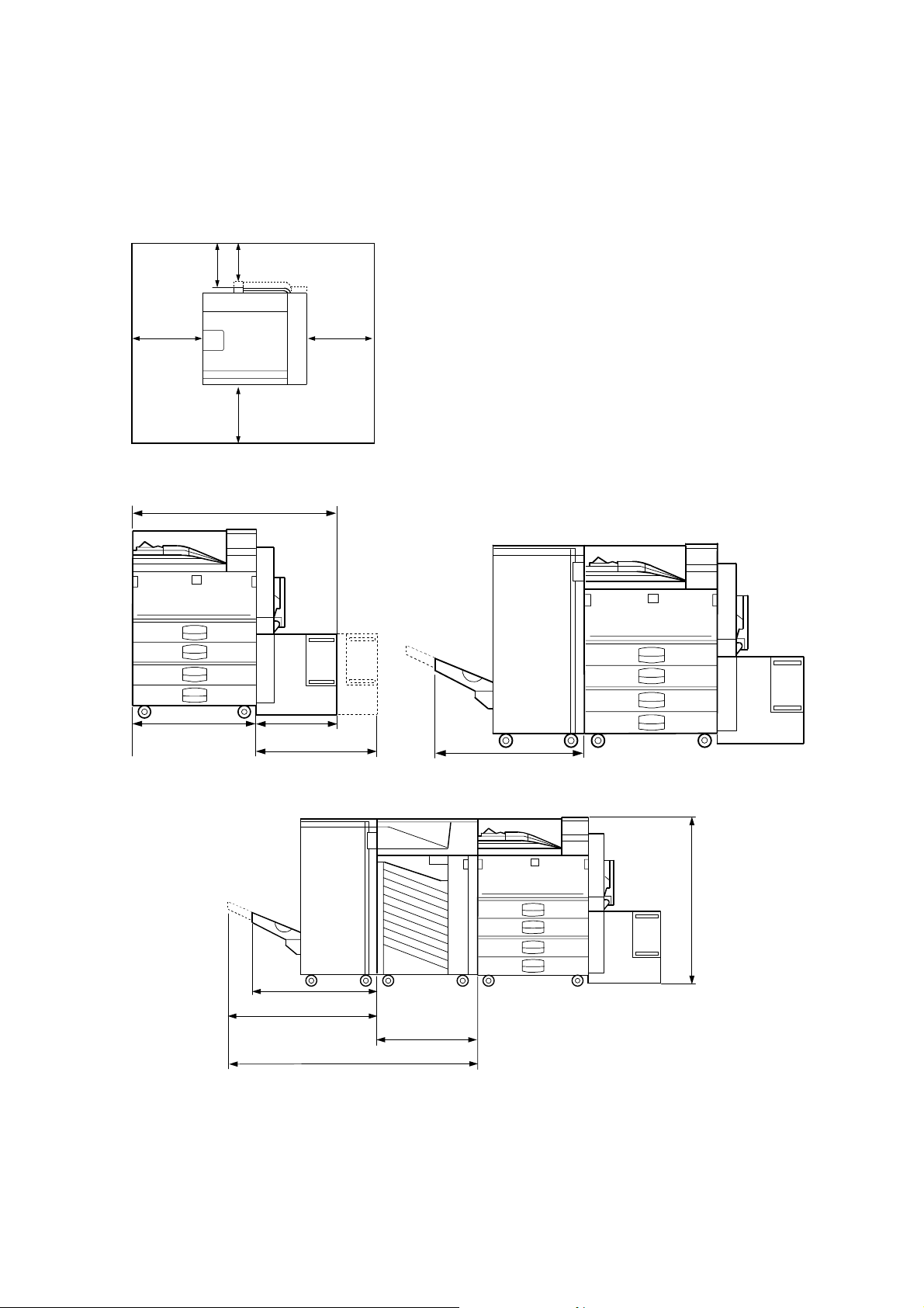
1.1.3 MACHINE SPACE REQUIREMENTS
Place the printer near the power source, providing clearance as shown:
C
A: In Front: > 75 cm (29.6")
B: Left: > 10 cm (4")
C: To Rear: > 10 cm (4")
D: Right: > 45 cm (17.8")
B
G065I000.WMF
G065I001.WMF
630 mm (24.8")
540 mm (21.3")
A
360 mm (14.2")
530 mm (20.9")
D
625 mm (24.6")
G065I002.WMF
970 mm (38.2")
625 mm (24.6")
720 mm (28.4")
600 mm (23.6")
1320 mm (52")
G065I003.WMF
The 75 centimeters recommended for the space at the fron t is for pu lling out the
paper tray only. If an operator stands in front of the printer, more space is required.
1-2

6 November, 2001 MACHINE INSTALLATION
1.1.4 POWER REQUIREMENTS
!
CAUTION
1. Make sure the plug is firmly inserted in the outlet.
2. Connect the printer to an independent power source. Avoid connecting
the printer to a power supply shared with another machine.
3. Always ground the machine.
1. Input voltage level: 120 V, 60 Hz: More than 12 A
220 V ~ 240 V, 50 Hz/60 Hz: More than 8 A
2. Permissible voltage fluctuation: ±10%
3. Do not set anything on the power cord.
1.2 MACHINE INSTALLATION
Refer to the Operating Instructions for details.
1.3 OPTIONAL UNIT INSTALLATION
Installation
The following options are available for this machine. Refer to the Operating
Instructions for how to install these options.
• PTU (Paper Tray Unit)
• 64/128/256 MB DIMMs
• HDD (Hard Disk)
• IEEE 1394
1.4 SYMBOLS USED IN TEXT
Screw: ! Connector: "
1-3

LCT INSTALLATION (A683) 6 November, 2001
1.5 LCT INSTALLATION (A683)
1.5.1 ACCESSORY CHECK
Check the quantity and condition of the accessories in the box against the following
list:
Description Q’ty
1. Joint Pin................................................................................. 2
2. Stepped Screw - M3x18......................................................... 4
3. Magnet Cover........................................................................ 1
4. NECR (-17, -27 machines)..................................................... 1
5. Installation Procedure............................................................ 1
1-4

6 November, 2001 LCT INSTALLATION (A683)
1.5.2 INSTALLATION PROCEDURE
A683I501.WMF
Installation
A683I604.WMF
!
CAUTION
A683I500.WMF
[A]
Switch off the main machine and unplug its power cord before starting the
following procedure.
NOTE: The Paper Tray Unit (G520) must be installed before installing the LCT.
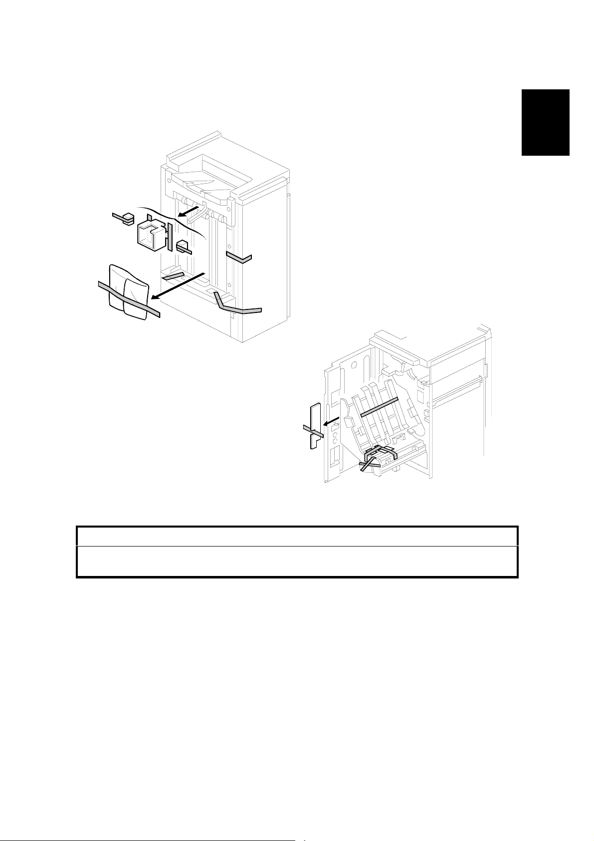
1. Unpack the LCT and remove the tapes.
2. Open the right cover [A] of the paper tray unit.
3. Open the lower right cover [B] and cut the holding band [C].
NOTE: When cutting the hold i ng band, the upper part of the band should be
cut as shown. Otherwise, paper jams may occur.
[C]
[B]
4. Remove the right lower cover.
1-5
LCT INSTALLATION (A683) 6 November, 2001
[A]
[E]
[B]
[D]
[C]
A683I503.WMF
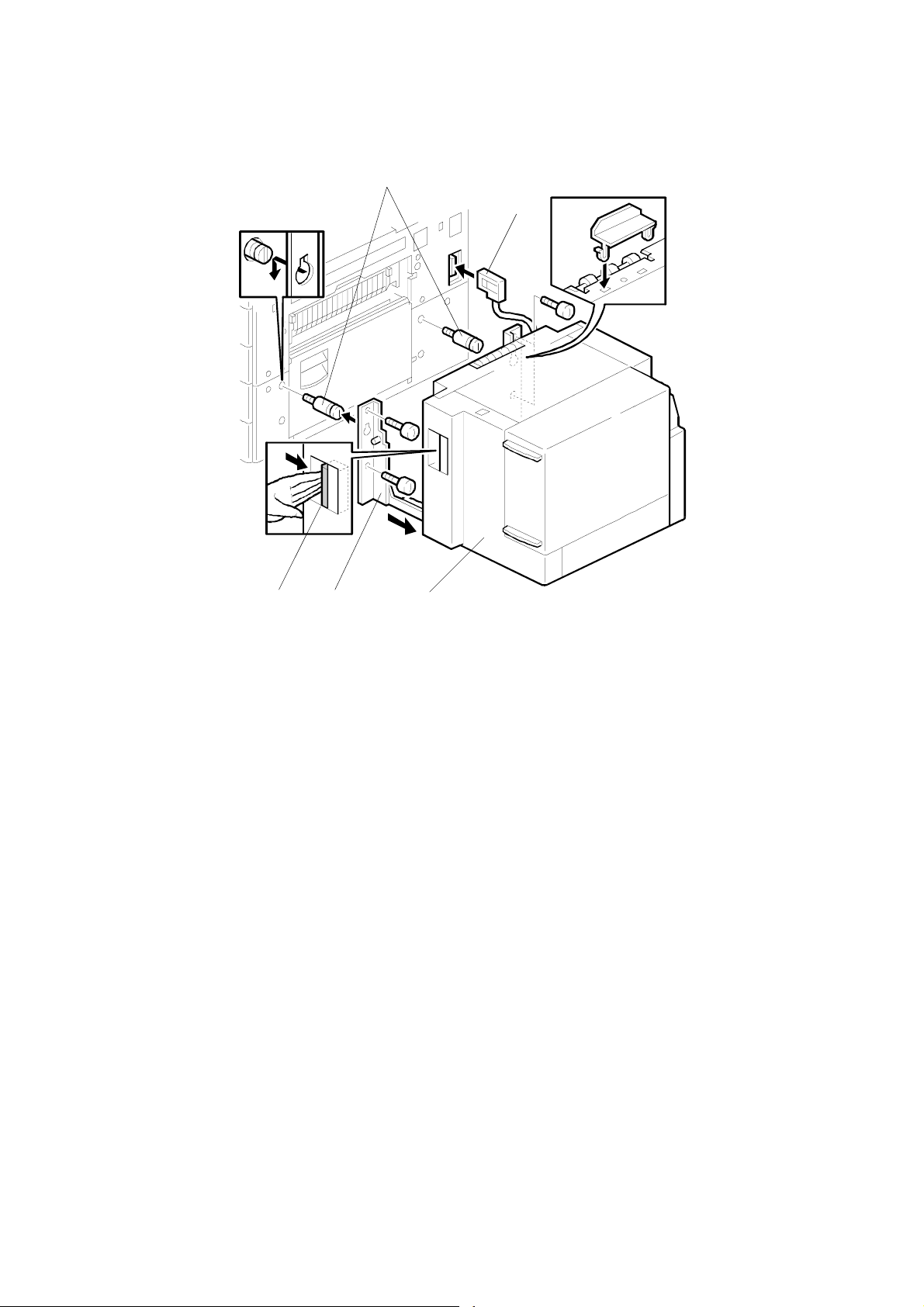
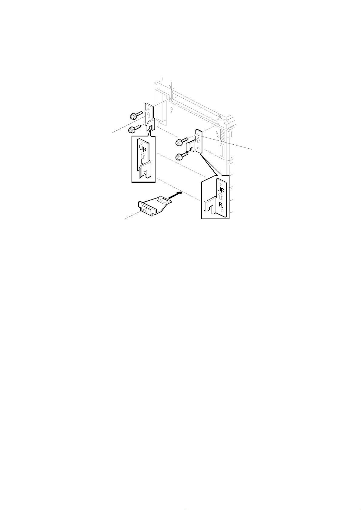
5. Install the joint pins [A].
6. Push the release lever [B] and slide the LCT to the right (front view).
7. Hang the LCT [C] on the joint pins, then secure the brackets [D] (! x 4).
8. Return the LCT to the previous position and connect the LCT cable [E].
9. Open the LCT cover and load the paper.
10. Turn on the ac switch and check the LCT operation.
1-6

6 November, 2001 BRIDGE UNIT INSTALLATION (B397)
1.6 BRIDGE UNIT INSTALLATION (B397)
1.6.1 ACCESSORY CHECK
Check the quantity and condition of the accessories in the box against the following
list:
Description Q’ty
1. Stepped Screw ...................................................................... 2
2. Connector Cover.................................................................... 1
3. Exit Mylar............................................................................... 2
4. Installation Procedure............................................................ 1
Installation
1-7
BRIDGE UNIT INSTALLATION (B397) 6 November, 2001
1.6.2 INSTALLATION PROCEDURE
[A]
[B]
[E]
B397I401.WMF
B397I407.WMF
!
CAUTION
[D]
[C]
B397I500.WMF
Switch off the main machine and unplug its power cord before starting the
following procedure.
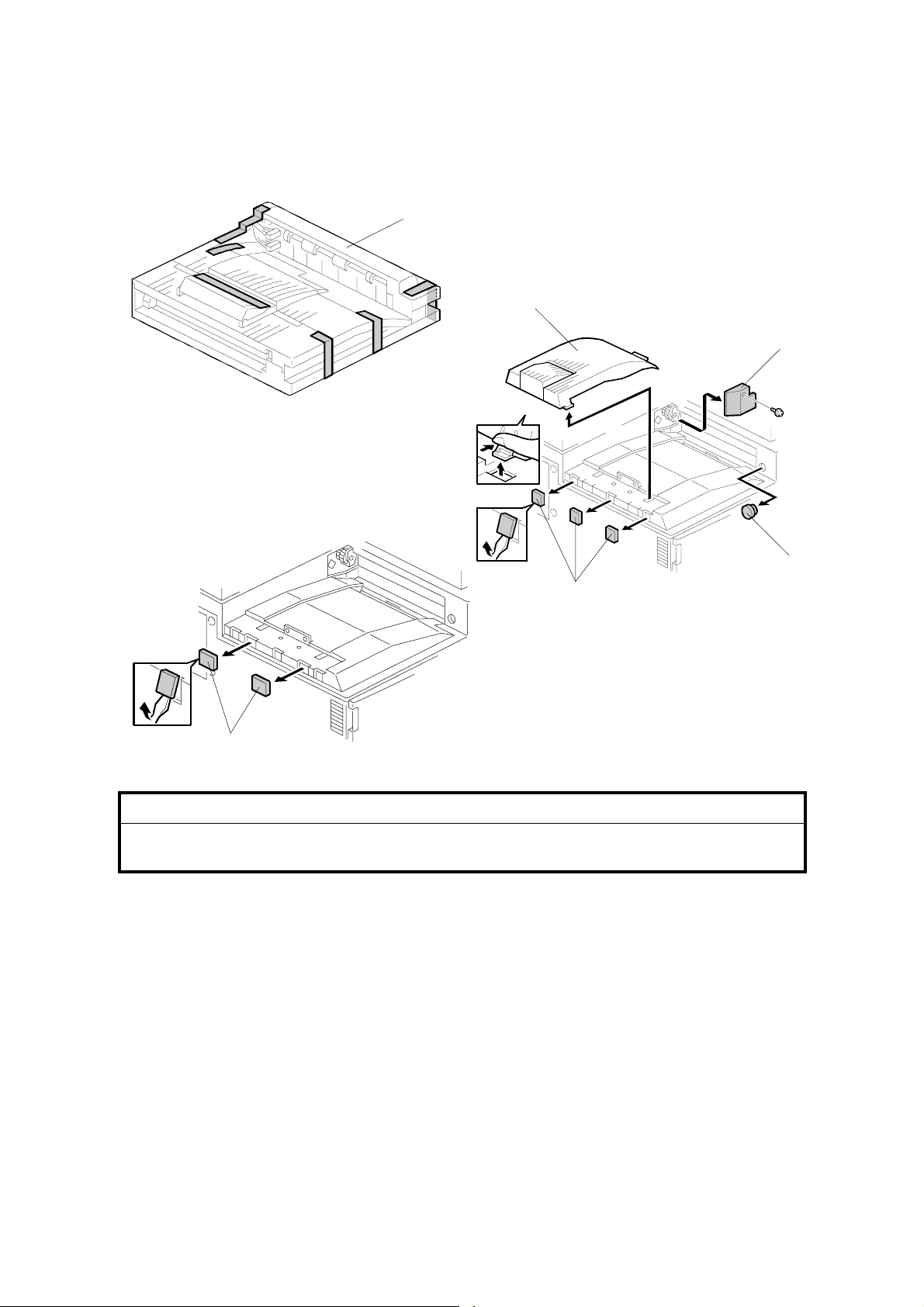
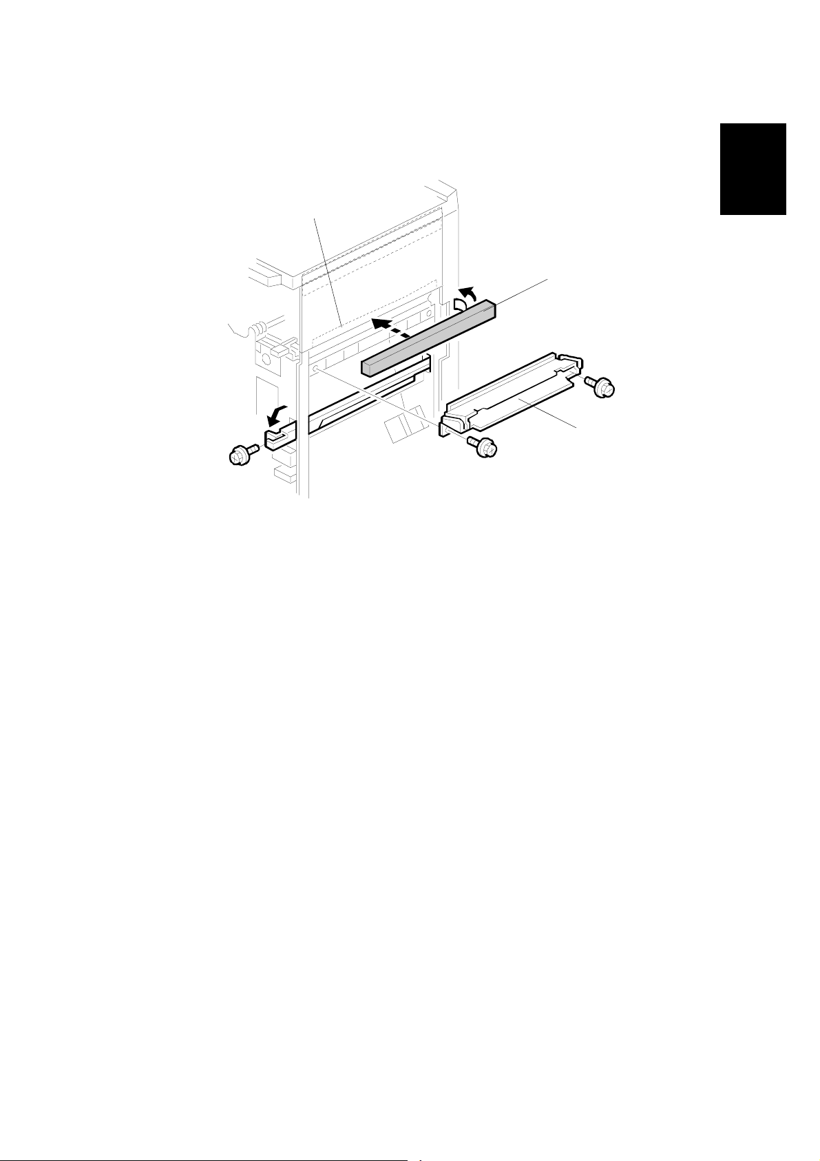
1. Unpack the bridge unit [A] and remove all tapes and shipping retainers.
2. Remove the inner tray [B].
3. On the side of the machine, remove the three small covers [C].
If the optional external output tray (A825) will be installed (instead of a
finisher), do Step 4.
[F]
4. Remove the two small covers [D].
5. Remove the cover [E] (! x 1)
6. Remove the cap [F].
7. Remove the paper height sensor (! x 2, " x 1)
1-8
6 November, 2001 BRIDGE UNIT INSTALLATION (B397)
[A]
[E]
B397I402.WMF
[B]
[D]
Installation
[C]
B397I444.WMF
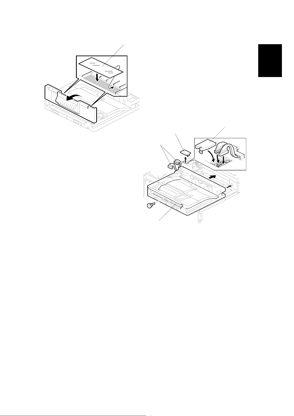
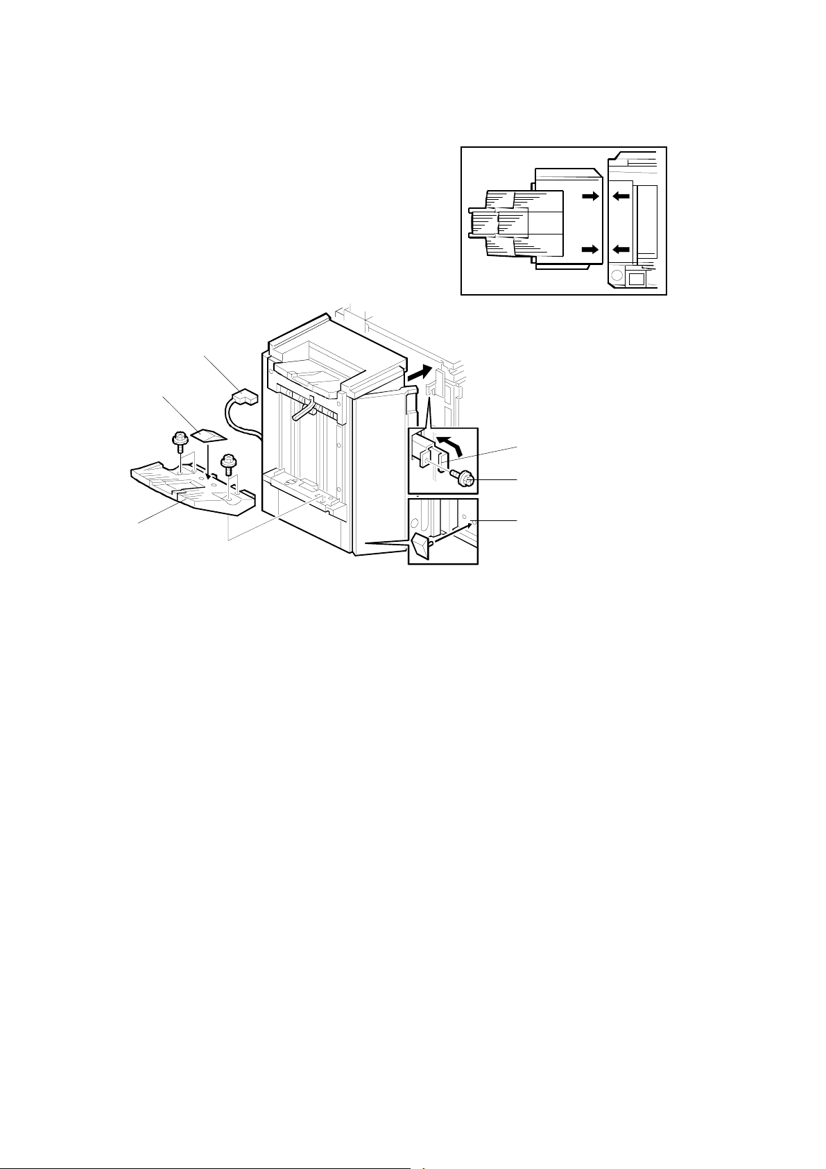
8. If an optional finisher is to be installed, attach two mylars [A] to the bridge unit.
9. Remove the cover [B].
10. Install the bridge unit [C] (! x 2).
11. Connect the bridge unit I/F harnesses [D] (" x 2).
12. Install the connector cover [E].
13. Turn on the main switch and check the bridge unit operation (make sure that
there are no paper jams).
1-9

1000-SHEET FINISHER INSTALLATION (A681) 6 November, 2001
1.7 1000-SHEET FINISHER INSTALLATION (A681)
1.7.1 ACCESSORY CHECK
Check the quantity and condition of the accessories in the box against the following
list:
Description Q’ty
1. Front Stand............................................................................ 1
2. Rear Stand............................................................................. 1
3. Knob Screw ........................................................................... 1
4. Screw - M4x12....................................................................... 6
5. NECR (-17 machine) ............................................................. 1
6. Installation Procedure............................................................ 1
7. Screw - M4x10....................................................................... 1
8. Tray ....................................................................................... 1
9. Snap ring ............................................................................... 1
1-10
6 November, 2001 1000-SHEET FINISHER INSTALLATION (A681)
1.7.2 INSTALLATION PROCEDURE
A681I701.WMF
Installation
A681I702.WMF
!
CAUTION
Switch off the main machine and unplug its power cord before starting the
following procedure.
NOTE: The bridge unit (B397) and paper tray unit (G520) must be installed before
installing this finisher.
If the mailbox (G909) will be installed, first install the mailbox, then the
bridge unit for the mailbox (G912), and finally install the finisher.
1. Unpack the finisher and remove the tapes and retainers.
1-11

1000-SHEET FINISHER INSTALLATION (A681) 6 November, 2001
[A]
[C]
[B]
A681I704.WMF
[D]
[E]
A681I705.WMF
2. Fasten [A] (! x 2) loosely.
3. Hang the front stand [B] and rear stand [C] on the screws installed in step 2.
4. To secure the front and rear stands tighten [A] (! x 2) and secure the stands
(! x 4).
5. At the front, use handle [D] to pull out the stapler unit.
6. Remove the locking lever [E] (! x 1).
7. Align the finisher on the stands, and lock it in place by pushing the locking
lever.
8. Secure the locking lever (! x 1) and push the stapler unit into the finisher.
1-12
6 November, 2001 1000-SHEET FINISHER INSTALLATION (A681)
[F]
[C]
[A]
Installation
[D]
A681I706.WMF
[E]
[B]
9. Secure the finisher [A] (! x 1).
10. Adjust the securing knobs [B] under the front and rear stands until the finisher
is perpendicular to the floor.
11. Install the shift tray [C] (snap ring x 1).
NOTE: Make sure that the three pegs [D] fit into the slots [E] properly.
12. Connect the finisher cable [F] to the main machine.
13. Turn on the main power switch and check the finisher operation.
1-13

3000-SHEET FINISHER INSTALLATION (A697) 6 November, 2001
1.8 3000-SHEET FINISHER INSTALLATION (A697)
1.8.1 ACCESSORY CHECK
Check the quantity and condition of the accessories in the box against the following
list:
Description Q’ty
1. Front joint bracket.................................................................. 1
2. Rear joint bracket................................................................... 1
3. Entrance guide plate.............................................................. 1
4. Shift tray................................................................................. 1
5. Shift tray guide....................................................................... 1
6. Staple position decal.............................................................. 1
7. Screw - M3x6......................................................................... 2
8. Screw - M4x14....................................................................... 4
9. Screw - M3x8......................................................................... 4
10. Cushion ................................................................................. 1
11. Upper grounding plate........................................................... 1
12. Lower grounding plate........................................................... 2
13. NECR (-17 machine)............................................................. 1
14. Installation procedure ............................................................ 1
1-14
6 November, 2001 3000-SHEET FINISHER INSTALLATION (A697)
1.8.2 INSTALLATION PROCEDURE
Installation
A697I506.WMF
A697I507.WMF
!
CAUTION
Unplug the main machine power cord before starting the following
procedure.
NOTE: The bridge unit (B397) and paper tray unit (G520) must be installed before
installing this finisher.
If the mailbox (G909) will be installed, first install the mailbox, then the
bridge unit for the mailbox (G912), and finally install the finisher.
1. Unpack the finisher and remove the tapes.
1-15
3000-SHEET FINISHER INSTALLATION (A697) 6 November, 2001
[B]
[A]
[C]
A697I558.WMF
2. Install the front joint bracket [A] and rear joint bracket [B] (! x 2 ea.).
3. Peel off the backing of the double-sided tape that is attached to the lower
grounding plate [C].
4. Attach one lower grounding plate to the center position of the paper tray unit as
shown.
1-16
6 November, 2001 3000-SHEET FINISHER INSTALLATION (A697)
[B]
Installation
[A]
[C]
A697I559.WMF
5. Attach the cushion [A] at the position [B].
6. Install the entrance guide plate [C] (! x 2).
1-17
3000-SHEET FINISHER INSTALLATION (A697) 6 November, 2001
[C]
A697I534.WMF
[G]
[D]
[B]
[A]
[F]
A697I550.WMF
[E]
7. If the customer requires the punch unit, install it now, before attaching the
finisher to the machine. See ‘Punch Unit Installation’.
8. Open the front door of the finisher, and remove the screw [A] that secures the
locking lever [B]. Then pull the locking lever.
9. Align the finisher on the joint brackets, and lock it in place by pushing the
locking lever.
NOTE: 1) Before securing the locking lever, make sure that the top edges of
the finisher and the copier are parallel fro m front to rear as show n
[C].
2) Secure the locking lever (! x 1) and close the front door.
10. Install the shift tray guide [D] on the shift tray. If the customer does not wish to
install it on the shift tray, store it at the location [E].
NOTE: The shift tray guide helps to properly stack exiting paper. However, it
reduces the capacity of the shift tray by 50, from 3,000 to 2,950.
11. Install the shift tray [F] (! x 4).
12. Connect the finisher cable [G] to the main machine.
13. Turn on the main power switch and check the finisher operation.
1-18

6 November, 2001 PUNCH UNIT INSTALLATION (A812)
1.9 PUNCH UNIT INSTALLATION (A812)
1.9.1 ACCESSORY CHECK
Check the quantity and condition of the accessories in the box against the following
list:
Description Q’ty
1. Spacer - 2 mm....................................................................... 1
2. Spacer - 1 mm....................................................................... 2
3. Stepped screw - Short........................................................... 1
4. Stepped screw - Long............................................................ 1
5. Punch unit knob..................................................................... 1
6. Spring.................................................................................... 1
7. Harness - Long...................................................................... 1
8. Harness - Short...................................................................... 1
9. Hopper................................................................................... 1
10. Punch position decal.............................................................. 1
11. Tapping screw - M4x10.......................................................... 2
Installation
12. Screw with flat washer - M4x6............................................... 1
13. NECR..................................................................................... 1
1-19

PUNCH UNIT INSTALLATION (A812) 6 November, 2001
1.9.2 INSTALLATION PROCEDURE
[A]
[D]
[B]
A812I761.WMF
[C]
A812I763.WMF
!
CAUTION
Unplug the copier power cord and remove the 3,000-sheet finisher from the
copier before starting the following procedure.
1. Unpack the punch unit and remove the shipping retainers [A] (! x 4) and [B] (!
x 1).
2. Open the front door and remove the hopper cover [C] (! x 2).
3. Remove the finisher rear cover (! x 2) and remove the transport guide plate
[D] (! x 4).
1-20

6 November, 2001 PUNCH UNIT INSTALLATION (A812)
Installation
[A]
[B]
A812I510.WMF
[D]
[C]
4. Install the spacer [A] (thickness = 2 mm).
NOTE: There are three spacers in the accessory box. Do not lose the other
two spacers (1-mm) because they are used for adjusting the punch
hole position.
A812I765.WMF
5. Install the punch unit [B] and secure it with a long stepped screw [C].
6. Install the punch unit knob [D] (! x 1).
7. Secure the rear of the punch unit (! x 2).
1-21

PUNCH UNIT INSTALLATION (A812) 6 November, 2001
A812I767.WMF
A812I512.WMF
[A]
[E]
[B]
[C]
[D]
A812I511.WMF
[F]
8. Install the sensor bracket [A] (! x 1, spring x1).
9. Connect the harnesses [B].
NOTE: 1) The harness binders [C] must not be between the harness clamps [D].
2) The harness binder [E] must be positioned to the left of the harness
clamp.
10. When a three-punch-hole unit is installed: Turn on switch 1 of DIP SW 100
on the finisher control board.
11. Slide the hopper [F] into the finisher.
12. Reassemble the finisher and attach the 3000-sheet finisher to the copi er, then
check the punch unit function.
1-22

6 November, 2001 MAILBOX INSTALLATION (G909)
1.10 MAILBOX INSTALLATION (G909)
1.10.1 ACCESSORY CHECK
Check the quantity and condition of the accessories in the box against the following
list:
Description Q’ty
1. Front joint bracket.................................................................. 1
2. Rear joint bracket................................................................... 1
3. Exit guide mylar..................................................................... 1
4. Proof tray attachment............................................................ 1
5. Upper grounding plate........................................................... 1
6. Lower grounding plate........................................................... 2
7. Cushion ................................................................................. 1
8. Tapping screw - M4x14.......................................................... 4
9. Bin decals.............................................................................. 1
10. Installation procedure ............................................................ 1
Installation
1.10.2 REQUIREMENT OPTIONS FOR MAIN MACHINE
When the mailbox is going to be ins talled on this printer, the following options must
be installed first.
• Bridge unit type 450 (B397)
• Paper tray unit - PS430 (G520)
1-23

MAILBOX INSTALLATION (G909) 6 November, 2001
1.10.3 INSTALLATION PROCEDURE
G909I500.WMF
[B]
[A]
[C]
G909I559.WMF
!
CAUTION
Unplug the main machine power cord before starting the following
procedure.
NOTE: If a finisher will be installe d, f irst install this mailbox, then the bridge unit for
the mailbox (G912), and finally install the finisher.
1. Unpack the finisher and remove the pieces of tape.
2. Attach the front joint bracket [A] and rear joint bracket [B] to the main machine
(! x 2 ea.).
3. Peel off the backing of the double-sided tape that is attached to the lower
grounding plate [C].
4. Attach one lower grounding plate to the center of the bottom edge of the paper
tray unit as shown.
1-24

6 November, 2001 MAILBOX INSTALLATION (G909)
[B]
[A]
[C]
Installation
[D]
[E]
G909I550.WMF
5. Attach the cushion [A] to the position [B].
6. Open the front cover [C] of the mailbox, and remove the screw [D] that secures
the locking lever [E]. Then pull the locking lever.
1-25

MAILBOX INSTALLATION (G909) 6 November, 2001
[B]
G909I503.WMF
[A]
[C]
G909I552.WMF
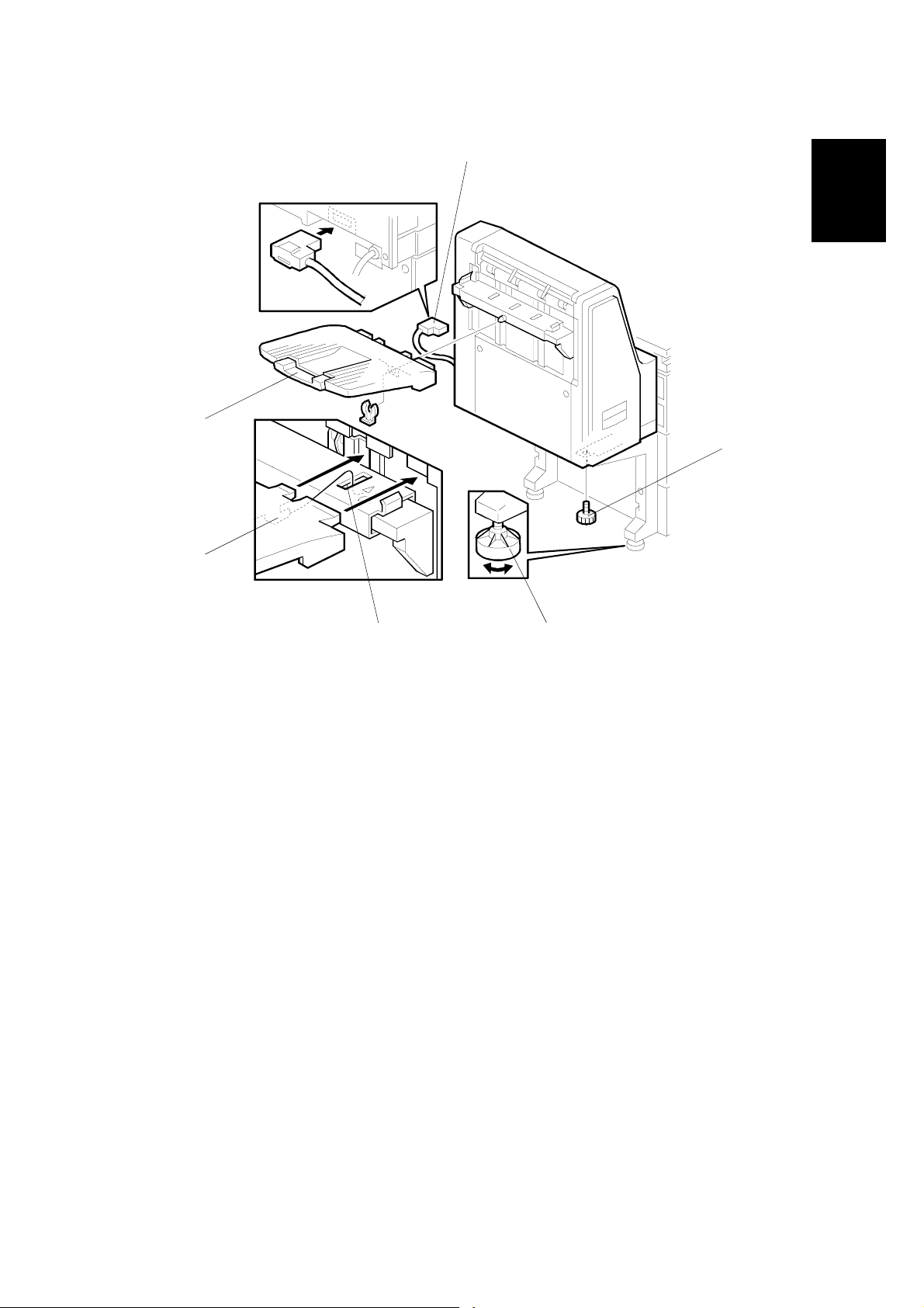
7. Align the mailbox on the joint brackets, and lock it in place by pushing the
locking lever [A].
8. Secure the locking lever (! x 1) and close the front door.
9. Connect the mailbox cable [B] to the main machine.
10. Peel off the backing of the double-sided tape that is attached to the proof tray
attachment [C].
11. Install the proof tray attachment on the proo f tray .
12. Turn on the main switch and check the mailbox operation.
1-26

6 November, 2001 BRIDGE UNIT FOR MAILBOX INSTALLATION (G912)
1.11 BRIDGE UNIT FOR MAILBOX INSTALLATION (G912)
1.11.1 ACCESSORY CHECK
Check the quantity and condition of the accessories in the box against the following
list:
Description Q’ty
1. Guide plate bracket............................................................... 1
2. Cable..................................................................................... 1
3. Cover switch.......................................................................... 1
4. Grounding bracket................................................................. 1
5. Finisher shielding plate.......................................................... 1
6. Screw - M4x8 ........................................................................ 9
7. Screw - M4x4 ........................................................................ 4
8. Screw - M3x6 ........................................................................ 2
Installation
1-27

BRIDGE UNIT FOR MAILBOX INSTALLATION (G912) 6 November, 2001
1.11.2 INSTALLATION PROCEDURE
[A]
[D]
G912I506.WMF
!
CAUTION
[A]
[B]
G909I508.WMF
Unplug the main machine power cord before starting the following
procedure.
[E]
[C]
NOTE: The bridge unit for the mailbox must be installed when both the mailbox
and a finisher will be installed. Install the mailbox first, then this bridge unit,
and finally the finisher
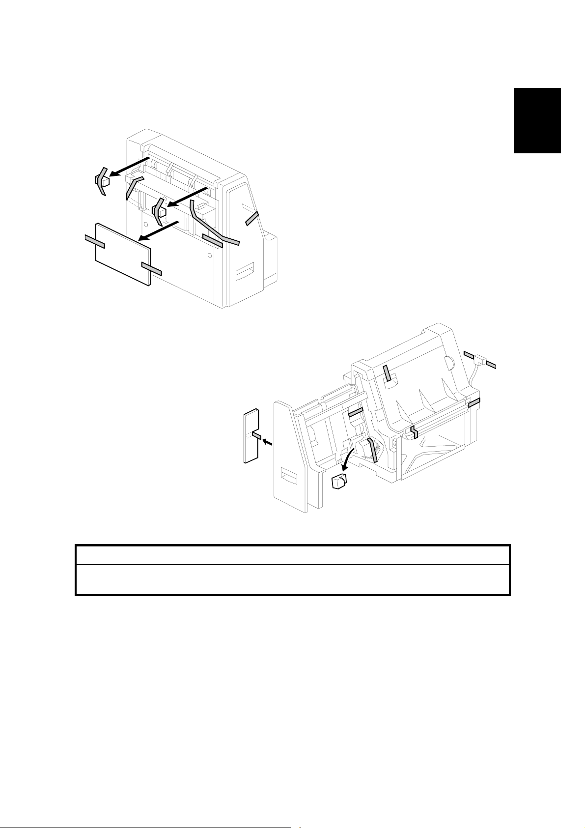
1. Unpack the bridge unit and remove the shipping retainers [A].
NOTE: Do not remove the protective sheet [B] at this time.
2. Remove the mailbox if it has been installed.
3. Remove the rear cover [C] of the mailbox (! x 8).
4. Remove the proof tray unit [D] (! x 6, " x 1).
5. Remove the cover [E].
1-28

6 November, 2001 BRIDGE UNIT FOR MAILBOX INSTALLATION (G912)
G912I503.WMF
[D]
[A]
[F]
[B]
Installation
[C]
G912I504.WMF
[E]
G912I505.WMF
[D]
6. Open the left front cover [A] of the mailbox, and remove the inner plate [B] (! x
3).
7. Install the guide plate bracket [C] (! x 4 - M4x4).
8. Route the cable [D] and clamp it as shown.
9. Connect the cover switch [E] to the cable then install the cover switch (! x 2 M4x8).
10. Remove the paper guide plate [F] (! x 2).
1-29

BRIDGE UNIT FOR MAILBOX INSTALLATION (G912) 6 November, 2001
[B]
G912I501.WMF
[F]
G912I508.WMF
[A]
[C]
[D]
[E]
G912I507.WMF
[H]
[G]
[H]
11. Pull up the tab [A] of the protective sheet.
NOTE: 1) Do not remove the protective sheet at this time.
2) Make sure that all mylars are held between the two folded halves of
the protective sheet.
12. Turn over the bridge unit [B] and insert the protective sheet [C] into the gap [D]
between the paper guides, then put the bridge unit on the mailbox [E].
NOTE: When holding the bridge unit, do not touch the timing belt. Otherwise
the timing belt may come off the gear.
13. Remove the tape [F] for the protective sheet.
14. Open the upper paper guide [G] then pull out the protective sheet [H].
NOTE: Check that all mylars are set into the gap between the paper guides.
1-30

6 November, 2001 BRIDGE UNIT FOR MAILBOX INSTALLATION (G912)
[C]
G912I509.WMF
[C]
[B]
[B]
[D]
[A]
[E]
Installation
[B]
[B]
G912I513.WMF
[G]
G912I510.WMF
[F]
15. Secure the bridge unit [A] (! x 4 - M4x8).
16. Route the cables [B] through the openings [C].
17. Route the solenoid harness [D] through the opening [E].
18. Connect the cables to the solenoid and sensors and clamp the cable as shown.
19. Reinstall the rear cover and proof tray unit.
20. Install the mailbox on the main machine (refer to the Mailbox Installation
procedure for more detail).
If installing the 3000-sheet finisher (A697), do steps 21 to 25.
21. Install the front joint bracket [F] and rear joint bracket [G] which are contained in
the finisher’s accessory box.
1-31

BRIDGE UNIT FOR MAILBOX INSTALLATION (G912) 6 November, 2001
[B]
G912I502.WMF
[A]
[C]
G912I512.WMF
22. Remove the seal [A].
23. Attach the grounding bracket [B] (! x 3 - M4x8).
24. Attach the shielding plate [C] to the finisher (! x 2 - M3x8).
25. Attach the finisher to the mailbox (refer to the finisher installation procedure).
26. Turn on the main switch of the main machine and check the bridge unit
operation. (Select a print mode that uses the finisher.)
1-32

6 November, 2001 PM TABLES
2. PREVENTIVE MAINTENANCE SCHEDULE
2.1 PM TABLES
2.1.1 PM TABLES FOR THE PRINTER
Two maintenance kits are provided for customers.
NAME CONTENTS
Maintenance Kit Type 4510 A PCDU (Photo Conductor Cle ani ng/Development Unit)
Maintenance Kit Type 4510 B Fusing Unit and Transfer Unit
Components marked with an asterisk (*) should be inspected, serviced, and
replaced without the maintenance kits.
NOTE: Amounts mentioned as the PM interval indicate the number of prints.
Symbol key: C: Clean, R: Replace, L: Lubricate, I: Inspect
EM 150K 300K 450K NOTE
PCDU
DRUM (OPC) AREA
Charge Roller* R R R
Cleaning Roller* R R R
Quenching Lamp C Dry cloth
Pick-off Pawl s* R R R
Spurs C C C Dry cloth or alcohol
ID Sensor
CCC
Perform SP3001-02 after
blower brush cleaning.
Preventive
Maintenance
CLEANING UNIT
Drum Cleaning Blade* R R R
Cleaning Entrance Seal
Side Seal I I I
DEVELOPMENT
Development Drive Gears I I I Replace every 5 PM (750 K)
Development Filter* R R R
Developer* I R I
Entrance Seal I I I
Side Seal I I I
Development Roller C C C Dry cloth
CCC
Blower brush, replace if
required.
2-1

PM TABLES 6 November, 2001
EM 150K 300K 450K NOTE
PAPER FEED
Registration Roller CCCCWater or alcohol.
Paper Feed Roller* I R R R
Separation Roller* I R R R
Pick-up Roller* I R R R
Paper Feed Roller
(By-pass feed table)*
Separation Roller
(By-pass feed table)*
Pick-up Roller
(By-pass feed table)
Paper Feed Guides C C C Water or alcohol.
Relay Rollers C C C Water or alcohol.
Bottom Plate Pad C C C Water or alcohol.
Bottom Plate Pad
(By-pass feed)
Registration Sensor C C C Blower brush
Paper Feed Roller Gear
(By-pass feed)
I RRR
I RRR
I RRR
CCC
LLL
Check counter value for each
(SP7204). If ≥ 150 K, replace
roller. After replacing the roller,
do SP7816 to reset counter.
Water or alcohol.
Silicone Grease G-50 1. *
DUPLEX UNIT
Upper Transport Roller C C C Water or alcohol.
Lower Transport Roller C C C Water or alcohol.
TRANSFER BELT UNIT
Transfer Belt* CRRRDry cloth
Transfer Belt Cleaning
Blade*
Transfer Belt Rollers C C C Dry cloth
Entrance Seal C C C Dry cloth
Transfer Entrance GuideCCCCDry cloth
Used Toner Tank I C C C Empty the tank.
FUSING UNIT/PAPER EXIT
Fusing Entrance and Exit
Guide Plates
Hot Roller* R R R
Pressure Roller* R R R
Fusing Thermistors* R R R
Cleaning Roller C C C Water or alcohol.
Cleaning Roller Bushings L L L Grease: Barrierta JFE 55/2
Hot Roller Strippers* C R C Water or alcohol.
Paper Exit Guide Ribs C C C Water or alcohol.
Exit Sensor C C C Blower brush
RRR
CCC
Water or alcohol.
DRIVE
Drive Belts I Replace if necessary
2-2

6 November, 2001 PM TABLES
2.1.2 PM TABLES FOR OPTIONS
NOTE: Amounts mentioned as the PM interval indicate the number of prints.
Symbol key: C: Clean, R: Replace, L: Lubricate, I: Inspect
EM 150K 300K 450K NOTE
PAPER TRA Y UNIT G520
Paper Feed Rollers R R R
Pick-up Rollers R R R
Separation Rollers
RRR
Relay Rollers C C C Dry or damp cloth
Bottom Plate Pad C C C Dry or damp cloth
EM 150K 300K 450K NOTE
LCT A683
Paper Feed Roller
RRR
Pick-up Roller* R R R
Separation Roller* R R R
Bottom Plate Pad C C C Dry or damp cloth
Check counter with SP7204. I f
≥ 150 K, replace roller. After
replacing the roller, do SP7816
to reset counter.
Check counter with SP7204. I f
≥ 150 K, replace roller. After
replacing the roller, do SP7816
to reset counter.
Preventive
Maintenance
EM 150K 300K 450K NOTE
1000-SHEET/3000- SHE ET FINI SH E R
Rollers C Water or alcohol.
Brush Roller (A681) IIIIReplace if required.
Discharge Brush CCCCDry cloth
Sensors C Blower brush
Jogger Fences IIIIReplace if required.
Punch Waste Hopper IIIIEmpty hopper.
* Note: Lubricate the paper feed clutch
gear [A] with Silicone Grease
G501 every P.M.
[A]
2-3
G065P500.WMF

6 November, 2001 GENERAL CAUTIONS
3. REPLACEMENT AND ADJUSTMENT
3.1 GENERAL CAUTIONS
!
CAUTION
To avoid damage to the transfer belt, drum, or development unit when it is
removed or re-installed, never turn off either power switch while electrical
components are active.
!
CAUTION
Turn off the main power switch and unplug the machine before attempting
any of the procedures in this section.
3.1.1 LASER UNIT
1. Do not loosen the screws that secure the LD drive board to the laser diode
casing. Doing so would throw the LD unit out of adjustment.
Adjustment
Replacement
2. Do not adjust the variable resistors on the LD unit, as they are adjusted in the
factory.
3. The polygon mirror and F-theta lenses are very sensitive to dust. Do not open
the optical housing unit.
4. Do not touch the glass surface of the polygon mirror motor unit with bare
hands.
5. After replacing the LD unit, do the laser beam pitch adjustment. Otherwise, an
SC condition will be generated.
3.1.2 USED TONER
1. Dispose of used toner in accordance with local regulations. Never throw toner
into an open flame, for toner dust may ignite.
3-1

SPECIAL TOOLS AND LUBRICANTS 6 November, 2001
3.2 SPECIAL TOOLS AND LUBRICANTS
3.2.1 SPECIAL TOOLS
Part Number Description Q’ty
A2309003 Adjustment Cam – Laser Unit 1
A2309004 Positioning Pin – Laser Unit 1
A2309352 Flash Memory Card – 4MB 1
A2309351 Case – Flash Memory Card 1
G0219350 Parallel Loopback Connector 1
3.2.2 LUBRICANTS
Part Number Description Q’ty
A2579300 Grease Barrierta S552R 1
52039501 Silicone Grease G-501 1
3.2.3 SYMBOLS USED IN TEXT
Screw: ! Connector: " C-clamp (snap ring): # E-clamp: $
3-2

6 November, 2001 FRONT DOOR
3.3 FRONT DOOR
[A]
[B]
1. Open front door.
2. Front door. Left pin [A], right pin [B].
3.4 DUPLEX UNIT
[B]
[A]
G065R951.WMF
[C]
[D]
Adjustment
Replacement
G065R003.WMF
1. Connector cover [A] (! x 1)
2. Duplex connectors [B] (" x 2)
3. Duplex support arm [C] (# x 1)
4. Duplex unit [D]
NOTE: Grip the duplex unit with both hands, slowly rotate it towards you and
then lift up.
3-3

UPPER RIGHT COVER 6 November, 2001
3.5 UPPER RIGHT COVER
[C]
[B]
[A]
G065R945.WMF
NOTE: Work carefully to avoid damaging the development roller.
1. Duplex unit (☛ 3.4)
2. Transfer belt unit (☛ 3.12.1)
3. Metal support arm [A] (! x 1)
4. Band support arm [B] (loop fastener)
5. Connector [C] (" x 1)
6. Upper right cover (# x 1, bushing x 1)
3-4

6 November, 2001 BY-PASS TRAY UNIT
3.6 BY-PASS TRAY UNIT
[B]
[C]
[D]
[A]
G065R952.WMF
Use this procedure to remove the complete by-pass tray unit from the machine. If
you wish to remove only the table, or some of the components of this unit, ☛ 3.15.
1. Duplex unit (☛ 3.4)
2. Left cover [A] (! x 1)
3. Right cover [B] (! x 1)
4. Connectors [C] (" x 2)
5. By-pass unit [D] (! x 4)
NOTE: After removing the screws, lift to unhook the by-pass tray unit from the
frame of the machine.
Adjustment
Replacement
3-5

REAR COVERS 6 November, 2001
3.7 REAR COVERS
3.7.1 REAR UPPER COVER
[B]
[A]
G065R953.WMF
1. Left corner cover [A] (! x 2)
2. Rear upper cover [B] (! x 2)
3.7.2 REAR LOWER COVER
[A]
G065R954.WMF
1. Rear lower cover [A] (! x 4)
3-6

6 November, 2001 LEFT COVERS
3.8 LEFT COVERS
3.8.1 LEFT UPPER COVER
[A]
Adjustment
Replacement
[B]
1. Rear left corner cover [A] (! x 2)
2. Left upper cover [B] (! x 4)
G065R955.WMF
3-7

LEFT COVERS 6 November, 2001
3.8.2 OPERATION PANEL
[A]
[D]
[B]
[C]
G065R919.WMF
!
WARNING
The fusing unit below the cover is hot. Allow the machine to cool for a few
minutes before you begin the procedure.
1. Fusing unit cover [A] (caps x 2, ! x 2)
NOTE: Insert the tip of a screwdriver into the slot to release the plastic hook
and lift. Exert very little pressure to avoid breaking the hooks.
2. After removing the screws, slide cover [B] forward to remove it.
NOTE: Before re-installing the cover, open the duplex unit and carefully insert
the brackets on the bottom of the cover into the slots [C].
3. Operation panel [D] (! x 2, " x 2)
NOTE: Turn over the fusing unit cover and pull off the operation panel to
expose the connector.
3-8

6 November, 2001 LEFT COVERS
3.8.3 PAPER OUTPUT TRAY
[B]
[A]
G065R920.WMF
No Bridge Unit Installed
1. Sub copy tray [A]
2. Paper sensor ass’y [B] (! x 2)
[D]
[E]
[C]
G065R921.WMF
Adjustment
Replacement
3. Cover [C] (! x 1)
4. Paper output tray [D] (! x 3)
5. If the duct on the bottom of the paper output tray base hangs up on the vertical
support [E] below, reach under and pull the duct up over the support.
Bridge Unit Installed
1. Bridge unit [A] (! x 2, " x 2)
2. Paper output tray [B] (! x 3)
3. If the duct on the bottom of the paper output tray base hangs up on the vertical
support [E] below, reach under and pull the duct up over the support.
3-9

LASER UNIT 6 November, 2001
3.9 LASER UNIT
!
WARNING
Turn off the main power switch and unplug the machine before attempting
any of the procedures in this section. Laser beams can seriously damage
your eyes.
3.9.1 CAUTION DECAL LOCATIONS
Two caution decals are located in the laser section as shown below. (See the next
page for removal instructions.)
LASER-1.WMF
G065RLW.WMF
3-10
G060R951.WMF
LASER-3.WMF

6 November, 2001 LASER UNIT
3.9.2 LASER UNIT
[B]
[D]
G065R211.WMF
[C]
[B]
[A]
[F]
Adjustment
Replacement
[G]
G065R962.WMF
!
WARNING
[E]
Turn off the main power switch and unplug the machine before attempting
this procedure. Laser beams can seriously damage your eyes.
1. Open the front door and raise the toner bottle holder handle [A].
2. Front door (pins [B] x 2)
3. Inner cover [C] (! x 2, " x 2)
4. Shield glass [D]
5. Shield plate [E] (! x 2)
6. Laser unit connectors [F] (" x 5, " x 1 flat cable)
NOTE: Hold the LD board securely when disconnecting connectors.
7. Laser unit [G] (! x 2)
NOTE: When sliding out the laser unit, do not hold the LD board. Hold the
laser unit casing.
3-11

LASER UNIT 6 November, 2001
3.9.3 POLYGON MIRROR MOTOR
[A]
[B]
G065R994.WMF
1. Laser unit (☛ 3.9.2)
2. Laser unit cover [A] (! x 4, 2 hooks)
3. Polygon mirror motor [B] (! x 4, " x 1)
4. After replacing the motor, do the image adjustment. (☛ 3.20)
G065R201.WMF
3-12

6 November, 2001 LASER UNIT
3.9.4 LASER SYNCHRONIZATION DETECTOR
[A]
G065R206.WMF
1. Laser unit (☛ 3.9.2)
Adjustment
Replacement
2. Laser synchronization detector [A] (! x 1, " x 1).
3.9.5 LD UNIT
[A]
1. Laser unit (☛ 3.9.2)
G065R513.WMF
2. LD unit [A] (! x 3, " x 1)
NOTE: To avoid damaging the LD board, hold it securely when disconnecting
the connectors. Hold the laser unit casing.
3. After replacing the LD board, perform SP2109 to adjust the laser beam pitch
(described on the next page).
3-13

LASER UNIT 6 November, 2001
Laser Beam Pitch Adjustment
After replacing the LD board, do the laser beam pitch adjustment. There are two
procedures: one for 400 dpi, and one for 600 dpi. These use the following SPs.
SP2110 Test Mode Dpi (0: 400 dpi, 8: 600 dpi)
SP2109-01 LD Beam Pitch Adjustment – 400 dpi
SP2109-02 LD Beam Pitch Adjustment – 600 dpi
SP2109-03 LD Beam Pitch Adjustment – 400 dpi Initial Setting
SP2109-04 LD Beam Pitch Adjustment – 600 dpi Initial Setting
NOTE: If you do not have an SMC Report for reference, print the SMC Report so
you can look up and match the SP numbers below with the correct name.
1. Set SP2110 to 0 (for 400 dpi), or to 8 (for 600 dpi).
2. Execute SP2109-08 to reset all the beam pitch data.
3. For SP2109-01 input 144.
NOTE: The entry “144” is only a starting reference value that will allow the
machine to operate. It is only a starting point for adjustment.
4. Execute SP2109-03.
5. Print the test pattern onto A3 (11" x 17") paper using SP2902-03 no.15. (☛ 5
Service Tables, 5.1.2 Test Pattern Printing (SP2902).
6. On the test pattern write 144, the value of SP2109-01.
7. Change the value of SP2109-01 and then print another test pattern, repeating
steps 2 to 6. Print about 5 patterns with different values for SP2109-01 (e.g. 48,
96, 192, 240).
8. Check these test patterns. If the laser beam pitch is not correct, the image
looks like a black vertical stripe pattern (see the diagrams below).
NOTE: For example, if the pattern made with the value 192 has fewer obvious
stripes than the other printouts, the correct value is near 192.
9. Fine adjustment: Do steps 2 to 6 to adjust the laser beam pitch position until
thin lines are of uniform thickness (no stripes should appear on the printout).
NOTE: In step 3, input a value estimated to be correct (e.g., if 192 was the
closest, try 182), then do steps 4 and 5, then if necessary go back to
step 2 and try another value.
10. After adjusting the laser beam pitch for 400 dpi, adjust it for 600 dpi, using the
same procedure as for 400 dpi (use the SP modes for 600 dpi). Laser beam
pitch for 600 dpi should be 24 ~ 48 more than for 400 dpi.
Adjustment not complete
Adjustment complete
G065R553.WMFG065R552.WMF
3-14

6 November, 2001 PCDU
3.10 PCDU
3.10.1 PHOTOCONDCUTOR CLEANING/DEVELOPMENT UNIT
[B]
[A]
G065R905.WMF
[C]
Adjustment
Replacement
[C]
[D]
[E]
G065R906.WMF
1. Open the front door.
2. Lower the by-pass tray, open the duplex unit, and open the transfer unit right
cover.
3. Release the PCDU lock [A].
4. Hold the PCDU by the handle [B] and pull out slowly.
5. Remove the screws [C] (! x 3).
6. Pull the PCU horizontally then up [D] to separate it from the development unit
[E].
7. Cover the drum with a clean sheet of paper to protect it from exposure to light.
Assembly
1. With the PCU slightly offset, set it on top of the development unit, then carefully
slide it horizontally to ensure that the end of the toner supply shutter at the
toner supply port opens.
2. Check the exposed spring on the back of the PCDU.
• If the spring is spread open, the supply port is open.
• If the spring is not open, the supply port is shut. Slide the PCU back and
engage it correctly.
NOTE: If the supply port remains closed, no toner will reach the drum.
3-15

PCDU 6 November, 2001
3.10.2 DRUM
[C]
[B]
[A]
[D]
[E]
G065R907.WMF
G065R908.WMF
G065R304.WMF
1. PCDU (☛ 3.10.1)
CAUTION: Never touch the drum surface with bare hands.
2. Remove the toner cap [A] and use it to cover the toner port [B].
3. Turn the PCU upside down and remove the lower cover [C] (! x 2, pawls x 3)
4. Press at ➀ to release the charge roller [D], release the charge roller ➁, press
the drum [E] to the front, and then remove the drum ➂.
5. SP adjustments.
Charge Roller Bias Adjustment
2001-01
ID Sensor Initial Setting 3001-02 Initializes the ID sensor.
Image Transfer Current – Image Face 2301 01
Image Transfer Current – Image Back 2301 02
Image Transfer Current – Lead Edge Face 2301 03
Image Transfer Current – Image Face By-pass 2301 04
3-16
Set to the standard value
to ensure carrier is not
attracted to the drum.
Set to the default
settings.

6 November, 2001 PCDU
3.10.3 PICK-OFF PAWLS
[A]
Adjustment
Replacement
[B]
G065R305.WMF
1. Remove the drum. (☛ 3.10.2)
2. Pawl assembly [A]
3. Pick-off pawl [B] (spring x 1, spur x 1)
Pick-off pawl position adjustment
If the pick-off pawl has marked the drum with a line, adjust the position by:
• Changing the spur position.
• Changing the pick-off pawl assembly position
3-17

PCDU 6 November, 2001
3.10.4 CHARGE ROLLER AND CLEANING ROLLER
[B]
[C]
[D]
1. Remove the drum. (☛ 3.10.2)
2. Two snap rings [A] (# x 2)
3. Charge roller holder [B]
4. Charge roller [C]
NOTE: Do not touch the charge roller.
5. Cleaning roller [D].
6. SP Adjustment:
Charge Roller Bias Adjustment
Image Transfer Current - Image Face 2301 01
Image Transfer Current - Image Back 2301 02
Image Transfer Current - Lead Edge Face 2301 03
Image Transfer Current - Image Face By-pass 2301 04
2001-01
[A]
G065R500.WMF
Set to the standard value
(–1,480 V) to ensure
carrier is not attracted to
the drum.
Set to the default
settings.
3-18

6 November, 2001 PCDU
3.10.5 DRUM CLEANING BLADE
[A]
Adjustment
Replacement
1. Remove the drum. (☛ 3.10.2)
2. Remove the charge roller. (☛ 3.10.4)
3. Remove the drum cleaning blade [A] (! x 2).
G065R307.WMF
3-19

PCDU 6 November, 2001
3.10.6 ID SENSOR
[A]
[B]
G065R991.WMF
[C]
1. PCDU (☛ 3.10.1)
2. Fusing unit (☛ 3.14.1)
3. Development unit (☛ 3.11.1)
4. PCDU rail [A] (! x 2, " x 1)
5. ID sensor bracket [B] (! x 1, " x 1)
6. ID sensor [C] (! x 1)
7. Perform the ID sensor initial setting with SP3001-2 (☛ 5. Service Tables)
3-20

6 November, 2001 DEVELOPMENT
3.11 DEVELOPMENT
3.11.1 DEVELOPMENT UNIT
[A]
[B]
Adjustment
Replacement
G065R202.WMF
1. PCDU. (☛ 3.10.1)
NOTE: Spread paper on a clean flat surface that is free of pins, paper clips,
staples, screws or any other metal objects.
2. Separate the PCU [A] and development unit [B] (! x 3).
3. Set the development unit on the spread paper, and cover the exposed drum
with a clean piece of paper.
4. SP adjustment if you are temporarily installing a used development unit for test
purposes:
Vref Manual Set SP2220 Set TD Sensor reference voltage to 4.0 V.
TD Sensor Manual Setting SP2802-01 Adjusts TD sensor output.
(☛ 5. Service Tables)
3-21

DEVELOPMENT 6 November, 2001
3.11.2 DEVELOPMENT FILTER
[A]
[B]
G065R909.WMF
1. Development unit (☛ 3.11.1)
2. Upper development cover [A] (# x 2)
3. Development filter [B].
NOTE: Make sure that the surface with the red mark is facing up.
3-22

6 November, 2001 DEVELOPMENT
3.11.3 DEVELOPMENT ROLLER
[C]
1. Development unit (☛ 3.11.2)
2. Upper development cover (☛ 3.11.2)
3. Gear [A] (# x 1)
4. Joint bracket [B]
5. Development roller [C] (! x 2)
G065R910.WMF
[B]
[A]
Adjustment
Replacement
NOTE: 1) Work carefully to avoid scratching or nicking the development roller.
2) Make sure that the part is grounded (earthed) correctly.
3-23

DEVELOPMENT 6 November, 2001
3.11.4 DEVELOPER
[B]
G065R404.WMF
[A]
[C]
1. Development unit (☛ 3.11.1)
2. Remove the development roller (☛ 3.11.3)
3. Tip out the old developer [A]
[D]
G065R405.WMF
4. Turn drive gear [B] to ensure that no developer remains in the unit or on the
developer roller.
NOTE: Dispose of the used developer in accordance with local regulations.
Work carefully to avoid scratching or nicking the development roller.
5. Pour approximately 1/3 of the developer [C] evenly along the length of the
development unit.
6. Rotate the drive gear [D] to work the developer into the unit. Repeat [C] and [D]
until all toner is in the unit and level with the edges.
3-24

6 November, 2001 DEVELOPMENT
[A]
G065R518.WMF
Adjustment
Replacement
7. Reassemble the development unit
8. Cover the toner entrance hole [A] with a piece of paper.
9. Install the development unit in the machine.
10. Turn on the main power switch, make sure that the machine has warmed up,
then perform the TD sensor initial setting using SP2801.
NOTE: When performing this setting, cover the toner entrance hole with a
piece of paper. This prevents used toner falling from the PCU into the
development unit during the TD sensor initial setting and interfering
with the Vref setting (toner density reference voltage).
11. After performing the TD sensor initial setting, remove the sheet [A] from the
development unit.
3-25

DEVELOPMENT 6 November, 2001
3.11.5 TD SENSOR
[A]
G065R975.WMF
1. Remove the development unit (☛ 3.11.1)
2. Empty all developer from the development unit (☛ 3.11.4)
3. TD sensor [A] (! x 1)
NOTE: The TD sensor is attached to the casing with double-sided tape. Pry it
off with the flat head of a screwdriver. Use fresh double-sided tape to
re-attach the sensor.
4. Pour new developer into the development unit and perform the TD sensor initial
setting using SP2801.
NOTE: When performing the TD sensor initial setting, cover the toner entrance
hole with a piece of paper (☛ 3.11.4).
3-26

6 November, 2001 TRANSFER UNIT
3.12 TRANSFER UNIT
3.12.1 TRANSFER BELT UNIT
[A]
[B]
G065R501.WMF
Adjustment
Replacement
G065R522.WMF
NOTE: To avoid exposing the PCU drum to strong light, cover it with paper if the
right cover will be open for a long period.
1. Lower the by-pass tray, open the duplex unit, and open the right cover.
2. Transfer unit [A] (1 hook)
3. Transfer belt [B] (springs x 2, 1 hook)
NOTE: Avoid touching the transfer belt surface.
3-27

TRANSFER UNIT 6 November, 2001
3.12.2 TRANSFER BELT
[B]
[E]
[A]
[C]
[D]
[B]
G065R524.WMF
1. Remove the transfer belt unit. (☛ 3.12.1)
2. Belt drive gear [A]
3. Set screws [B] (! x 2)
4. Lay on a flat, clean surface and fold the unit to release the tension on the belt
[C].
5. Transfer belt [D]
NOTE: 1) Avoid touching the transfer belt surface.
2) Before installing the new transfer belt, clean all the rollers and shafts
with alcohol to prevent the belt from slipping.
3) When reinstalling the transfer belt, make sure that the belt is under the
pin [E].
4) To avoid damaging the transfer belt during installation, manually turn the
rollers and make sure that the new transfer belt is not running over the
edges of any of the rollers.
3-28

6 November, 2001 TRANSFER UNIT
3.12.3 CLEANING BLADE/TONER OVERFLOW SENSOR
[B]
[A]
Adjustment
Replacement
G065R911.WMF
Transfer Belt Cleaning Blade
1. Transfer belt unit. (☛ 3.12.1)
2. Transfer belt. (☛ 3.12.2)
3. Transfer belt cleaning blade [A] (! x 3)
NOTE: Avoid touching the edge of the new blade. Check the new blade for
dust or damage.
Toner Overflow Sensor
1. Transfer belt unit. (☛ 3.12.1)
2. Transfer belt. (☛ 3.12.2)
3. Transfer belt cleaning blade [A] (! x 3)
4. Turn over the transfer unit and empty the used toner in the transfer unit.
5. Toner overflow sensor [B] (! x 1, " x 3)
NOTE: Re-install the color-coded wires in the correct order.
R: Red, P: Purple, B: Blue
3-29

PAPER FEED 6 November, 2001
3.13 PAPER FEED
3.13.1 PICK-UP, SEP ARATION, AND FEED ROLLERS
[B]
[A]
[C]
G065R918.WMF
1. Paper tray
2. Pick-up roller [A]
3. Feed roller [B] (# x 1)
4. Separation roller [C] (# x 1)
NOTE: Do not touch the roller surface with bare hands. After installing the new
rollers, do SP7816 for the appropriate paper tray.
3-30

6 November, 2001 PAPER FEED
3.13.2 LOWER RIGHT COVER
[A]
[B]
G065R904.WMF
Adjustment
Replacement
1. Duplex unit (☛ 3.4)
2. By-pass tray (☛ 3.6)
3. LCT (if installed)
4. Lower right cover [A] (! x 5)
5. Vertical transport cover [B]
NOTE: Push the cover completely to the left and then press in on the right tab
to release the peg from the hole.
3-31

PAPER FEED 6 November, 2001
3.13.3 RELAY/UPPER PAPER FEED AND LOWER PAPER FEED CLUTCHES
[F]
[E]
[D]
[A]
[C]
G065R973.WMF
[B]
1. Rear lower cover (☛ 3.7.2)
2. First paper feed clutch bracket [A] (! x 2, bushing x 1)
3. Second paper feed clutch bracket [B] (! x 2, bushing x 1)
4. Drive bracket [C] (! x 1, spring x 1, bearing x 1)
5. Relay clutch [D] (" x 1)
6. Upper paper feed clutch [E] (" x 1)
7. Lower paper feed clutch [F] (" x 1)
3-32

6 November, 2001 PAPER FEED
3.13.4 UPPER PAPER FEED UNIT FOR TRAY 1
[B]
[B]
G065R900.WMF
1. Upper paper tray
2. Right lower cover (☛ 3.13.2)
[B]
[A]
[C]
G065R941.WMF
Adjustment
Replacement
3. Upper right cover (☛ 3.5)
4. Upper paper feed clutch [A] (☛ 3.13.3)
5. 3 relay gears [B]
6. Upper paper feed unit [C] (! x 2, " x 1)
3-33

PAPER FEED 6 November, 2001
3.13.5 LOWER P APER FEED UNIT FOR TRAY 2
G065R974.WMF
[B]
[C]
1. Lower the paper trays
2. Lower right cover (☛ 3.13.2)
[A]
[D]
[E]
G065R943.WMF
3. Lower paper feed clutch [A] (☛ 3.13.3)
4. Relay gears [B] (x 3)
5. Cover [C] (! x 2)
6. Gear [D] (x 1)
7. Lower paper feed unit [E] (! x 2, " x 1)
3-34

6 November, 2001 PAPER FEED
3.13.6 PAPER END/PAPER LIFT/RELAY SENSORS
[A]
[B]
[C]
[D]
G065R944.WMF
Adjustment
Replacement
1. Appropriate paper feed unit (☛ 3.13.4, 3.13.5)
2. Paper lift sensor [A] (" x 1)
3. Paper end sensor [B] (" x 1)
4. Relay sensor bracket [C] (! x 1, " x 1)
5. Relay sensor [D]
3-35

PAPER FEED 6 November, 2001
3.13.7 REGISTRATION SENSOR
[D]
[C]
[B]
[F]
G065R992.WMF
[A]
[G]
[I]
[J]
[H]
G065R993.WMF
1. Front door (☛ 3.3)
2. Rear upper cover (☛ 3.7.1)
3. Right door and transfer belt unit (☛ 3.5, 3.12.1)
4. PCU (☛ 3.10.1)
5. Development unit (☛ 3.12.1)
[E]
G065R922.WMF
6. Inner cover [A] (! x 2)
7. Front registration holder [B] (! x 1)
8. Front registration roller gear [C] ($ x 1)
9. Registration roller bushing [D] (spring x 1)
10. High voltage power supply board [E] (! x 3, " x 6)
11. Three flywheels [F] (! x 3)
12. Right rear cover [G] (! x 3)
13. Right cover switch bracket [H] (! x 1)
14. Rear registration holder [I] (! x 1)
15. Registration roller bushing [J] ($ x 1, spring x 1)
3-36

6 November, 2001 PAPER FEED
[B]
G065R934.WMF
[A]
[D]
16. Guide plate [A] and registration roller [B] (spring x 1, # x 1)
17. Registration guide plate [C] (! x 2, " x 1)
[E]
[C]
G065R935.WMF
Adjustment
Replacement
18. Sensor bracket [D] (! x 1)
19. Registration sensor [E] (! x 1, " x 1)
3-37

PAPER FEED 6 November, 2001
3.13.8 TRAY LIFT MOTOR
[A]
[C]
[B]
1. Rear lower cover (☛ 3.7.2)
2. Bracket [A] (! x 2)
3. Motor control board [B] (! x 2, " x 13)
4. Tray lift motor [C] (! x 2)
G065R964.WMF
3-38

6 November, 2001 PAPER FEED
3.13.9 FEED/DEVELOPMENT MOTOR
[B]
[A]
Adjustment
Replacement
[C]
1. Rear lower cover (! x 4) (☛3.7.2)
2. Rear upper cover (! x 4) (☛3.7.1)
3. Tray lift motor (☛ 3.13.8)
4. Support [A] (! x 2, harnesses x 2)
5. Timing belt [B] (Raise arm to release tension on belt.)
6. Feed/development motor [C] (! x 3, " x 2)
G065R982.WMF
3-39

FUSING 6 November, 2001
3.14 FUSING
3.14.1 FUSING UNIT
!
CAUTION
Allow the unit to cool before doing the following procedure.
[B]
[C]
[A]
1. Open the front door, duplex unit, and right door.
2. Set screw [A] (! x 1)
3. Fusing unit release lever [B]
4. Slide out the fusing unit [C]
NOTE: After removing the fusing unit, close the right cover.
G065R901.WMF
3-40

6 November, 2001 FUSING
3.14.2 FUSING UNIT EXIT GUIDE
[A]
G065R912.WMF
1. Fusing unit (☛ 3.14.1)
Adjustment
Replacement
2. Exit guide [A]
NOTE: Press the guide to the left and then press on the right end to release
the peg from the hole.
3.14.3 HOT ROLLER STRIPPERS
[A]
[B]
G065R913.WMF
1. Fusing unit (☛ 3.14.1)
2. Fusing unit cover [A] (! x 4)
NOTE: Note the positioning of the step screws (x 2) and set screws (x 2).
3. Hot roller strippers [B] (x 7), springs (x 7)
3-41

FUSING 6 November, 2001
3.14.4 FUSING LAMPS
[B]
[C]
[A]
G065R914.WMF
[E]
1. Fusing unit (☛ 3.14.1)
2. Fusing unit cover (☛ 3.14.3)
3. Fusing entrance guide [A] (! x 2)
4. Lower cover [B] (! x 1)
Left Side
5. Two terminals [C] (! x 2)
6. Center fusing lamp lead [D] (3 clamps)
[D]
G065R915.WMF
7. Bracket [E] (! x 1)
3-42

6 November, 2001 FUSING
Right Side
[B]
[C]
[D]
G065R607.WMF
[A]
Adjustment
Replacement
1. Two terminals [A] (! x 2)
2. Spring [B]
3. Connector bracket [C] (! x 2)
4. Bracket [D] (! x 2)
NOTE: To avoid breaking the fusing lamps, handle them with care. Avoid
touching the lamps with your fingers. Note the top/bottom positioning of
the fusing lamps as you remove them. The sizes of the holes in the
holder match the sizes of the ends of the 650 W lamp (red) and 550 W
lamp (brown).
5. Remove both fusing lamps.
3-43

FUSING 6 November, 2001
3.14.5 THERMISTORS AND THERMOSTATS
[B]
[A]
G065R917.WMF
[C]
[D]
G065R916.WMF
1. Fusing unit (☛ 3.14.1)
2. Fusing upper and lower cover (☛ 3.14.3, 3.14.4)
3. Center thermistor [A] (! x 1, " x 1, holder x 1)
4. End thermistor [B] (! x 1, " x 1, holder x 1)
CAUTION: The thermistors are thinly coated and extremely fragile. Handle with
care to avoid damaging them. They should be replaced every 150K.
5. Center thermostat [C] (! x 2)
6. End thermostat [D] (! x 2)
3-44

6 November, 2001 FUSING
3.14.6 HOT ROLLER/PRESSURE ROLLER
[C]
[A]
Adjustment
Replacement
[B]
1. Fusing unit (☛ 3.14.1)
2. Fusing upper and lower cover (☛ 3.14.3, 3.14.4)
3. Fusing lamp. (☛ 3.14.4)
4. Springs x 2 [A] (both sides)
5. Arms x 2 [B] (both sides)
6. Pawl bracket [C] (! x 4)
G065R902.WMF
3-45

FUSING 6 November, 2001
[D]
[A]
[B]
[E]
[C]
[B]
[F]
[G]
G065R903.WMF
7. Hot roller [A]
CAUTION: The hot roller is easily damaged. Always handle it carefully.
8. C-rings x 2 [B] (both ends)
9. Drive gear [C]
10. Bushings x 2 [D] (both ends)
11. Pressure roller [E]
12. Fusing knob [F] (! x 1)
13. Bushings x 2 [G] (both ends)
NOTE: 1) Before installing the new hot roller, peel off 3 cm (1 inch) from both
ends of the protective sheet on the new roller.
2) Never touch the surface of the rollers.
3) Work carefully to avoid damaging the surface of the hot roller.
4) The standard pressure roller spring position is the upper position.
5) When reinstalling the hot roller assembly and pressure roller
assembly, make sure that the flange position of the bushings is as
shown.
3-46

6 November, 2001 BY-PASS TRAY
3.15 BY-PASS TRAY
3.15.1 COVER REPLACEMENT
[D]
[A]
Adjustment
Replacement
[B]
1. Rear cover [A] (! x 1)
2. Front cover [B] (! x 1)
3. Hinge cover [C] (! x 1)
4. Upper cover [D] (! x 2)
5. Close duplex unit and pull out upper cover.
[C]
G065R540.WMF
3-47

BY-PASS TRAY 6 November, 2001
3.15.2 BY-PASS FEED/PICK-UP ROLLER
[C]
[B]
[A]
G065R541.WMF
1. Upper cover (☛ 3.15.1)
2. Lift up paper end feeler [A] to lock feeler in position.
NOTE: Before reinstalling the upper cover, return the paper end feeler to its
original position.
3. Replace the paper feed roller [B] (# x 1)
4. Replace the pick-up roller [C].
NOTE: Do not touch the roller surface with bare hands. After installing the new
rollers, do SP7816 for the bypass tray.
3-48

6 November, 2001 BY-PASS TRAY
3.15.3 BY-PASS SEPARATION ROLLER REPLACEMENT
[A]
Adjustment
Replacement
G065R542.WMF
1. Close the by-pass table.
2. Remove the separation roller [A] from the bottom (# x 1)
NOTE: Do not touch the roller surface with bare hands. After installing the new
rollers, do SP7816 for the bypass tray.
3-49

BY-PASS TRAY 6 November, 2001
3.15.4 PAPER END SENSOR/PICK-UP SOLENOID
[C]
[B]
[A]
G065R543.WMF
1. Upper cover (☛ 3.15.1)
2. Lift paper end feeler [A].
NOTE: Before reinstalling the upper cover, return the paper end feeler to its
original position.
3. Paper end sensor [B] (" x 1).
4. Pick-up solenoid [C] (! x 1, " x 1, spring x 1)
3-50

6 November, 2001 BY-PASS TRAY
3.15.5 PAPER SIZE SENSOR BOARD REPLACEMENT
[C]
[B]
[A]
G065R544.WMF
1. Hook [A]
2. Paper tray [B] (" x 1).
3. Size sensor board [C].
NOTE: To avoid breaking the hook of the paper size sensor board, handle it
carefully during removal.
Adjustment
Replacement
3-51

BY-PASS TRAY 6 November, 2001
3.15.6 BY-PASS TABLE REMOVAL
[A]
[B]
[C]
G065R505.WMF
Note: To remove the entire by-pass tray unit, and not just the table, ☛ 3.6
1. Hinge cover (☛ 3.15.1)
2. Harness [A] (" x 1).
3. Screws [B] (! x 2)
4. By-pass table [C].
CAUTION: To relieve pressure on the spring during removal, depress it as shown
in the illustration.
3-52

6 November, 2001 BY-PASS TRAY
3.15.7 PAPER FEED CLUTCH REPLACEMENT
[A]
G065R546.WMF
[C]
Adjustment
Replacement
1. By-pass tray
2. Paper feed unit [A] (! x 2, " x 1)
3. Rear bracket [B] (! x 3, clip x 1, bushing x 1)
4. Paper feed clutch [C] (" x 1)
[B]
G065R547.WMF
3-53

DUPLEX UNIT 6 November, 2001
3.16 DUPLEX UNIT
3.16.1 DUPLEX COVER REMOVAL
[A]
1. Duplex unit cover [A] (! x 4)
G065R101.WMF
3-54
 Loading...